Japan Radio JSS-296 MF/HF Radio Telephone User Manual 1
Japan Radio Co Ltd. MF/HF Radio Telephone 1
Contents
- 1. Pages 1 to 77
- 2. Pages 78 to 154
Pages 1 to 77

MF/HF Radio Equipment
JSS-296
Instruction Manual
blank

i
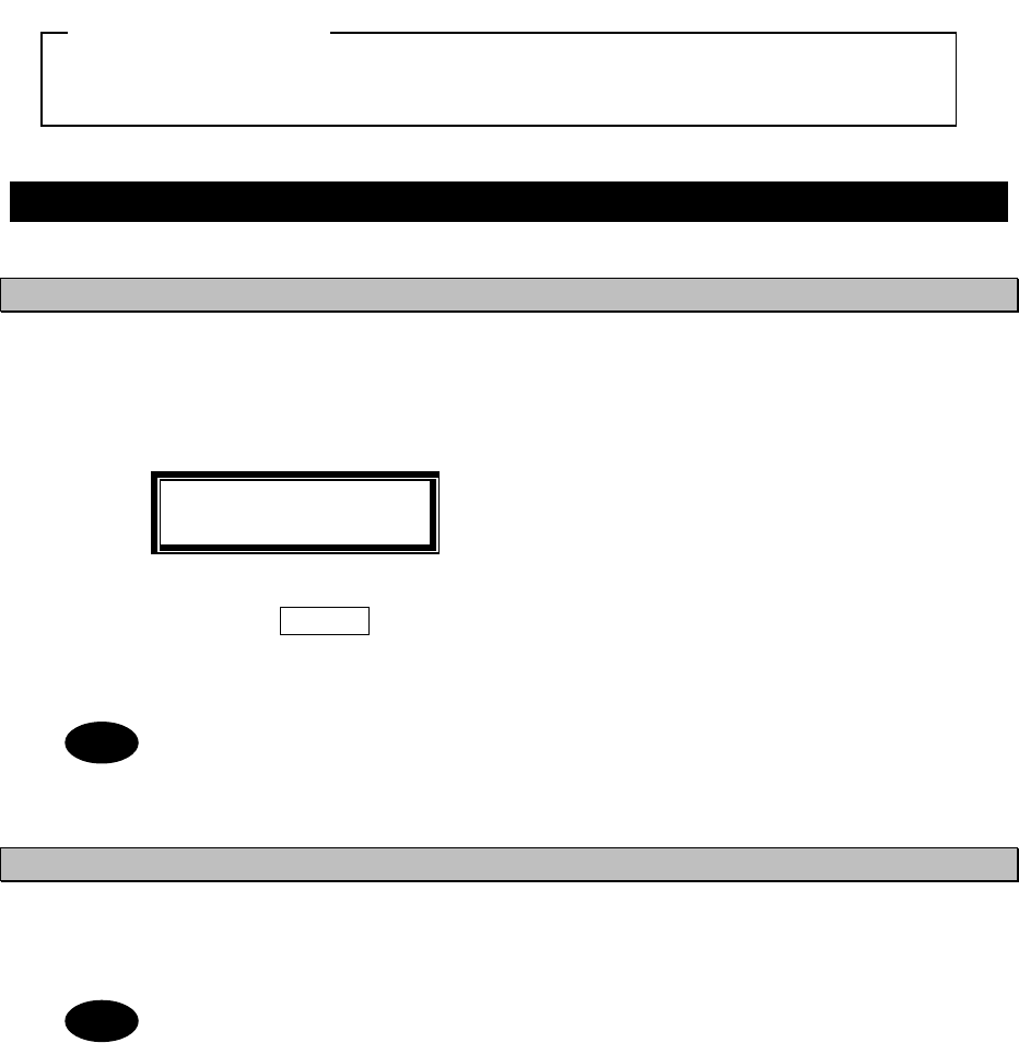
CAUTIONS AGAINST HIGH VOLTAGE
Radio and radar devices are operated by high voltages of anywhere from a few hundred volts up to many
hundreds of thousands of volts. Although there is no danger with normal use, it is very dangerous if contact
is made with the internal parts of these devices. (Only specialists should attempt any maintenance,
checking or adjusting.)
There is a very high risk of death by even a few thousand volts, in some cases you can be fatally
electrocuted by just a few hundred volts. To circumvent accidents, you should avoid contact with the
internal parts of these devices at all costs. If contact is inevitable as in the case of an emergency, you must
switch off the devices and ground a terminal in order to discharge the capacitors. After making certain that
all the electricity is discharged, only then can you insert your hand into the device. Wearing cotton gloves
and putting your free hand in your pocket, in order not to use both hands simultaneously, are also very
good methods of shock prevention.
Quite often, an injury occurs by secondary factors, therefore it is necessary to choose a sturdy and level
working surface. If someone is electrocuted it is necessary to thoroughly disinfect the affected area and
seek medical attention as soon as possible.
Cautions concerning treatment of electrocution victims
When you find an electrocution victim, you must first switch off the machinery and ground all circuits. If you
are unable to cut off the machinery, move the victim away from it using a non-conductive material such as
dry boards or clothing.
When someone is electrocuted, and the electrical current reaches the breathing synapses of the central
nervous system inside the brain, breathing stops. If the victim's condition is stable, he or she can be
administered artificial respiration. An electrocution victim becomes very pale, and their pulse can be very
weak or even stop, consequently losing consciousness and becoming stiff.
Administration of first aid is critical in this situation.

ii
First aid
☆Note points for first aid
Unless there is impending danger leave the victim where he or she is, then begin artificial respiration.
Once you begin artificial respiration, you must continue without losing rhythm.
(1) Make contact with the victim cautiously, there is a risk that you may get electrocuted.
(2) Switch off the machinery and then move the victim away slowly if you must.
(3) Inform someone immediately (a hospital or doctor, dial emergency numbers, etc.).
(4) Lay the victim on his or her back and loosen any constrictive clothing (a tie, or belt).
(5) (a) Check the victim's pulse.
(b) Check for a heartbeat by pressing your ear against the victim's chest.
(c) Check if the victim is breathing by putting the back of your hand or face near the victim's face.
(d) Check the pupils of the eyes.
(6) Open the victim's mouth and remove any artificial dentifrice, food or chewing gum. Leave the mouth
opened and flatten the tongue with a towel or by putting something into the mouth to prevent the
victim's tongue from obstructing the throat. (If he or she is clenching their teeth and it is difficult to
open the mouth, use a spoon or the like to pry open the mouth.)
(7) Continually wipe the mouth to prevent the accumulation of saliva.

iii
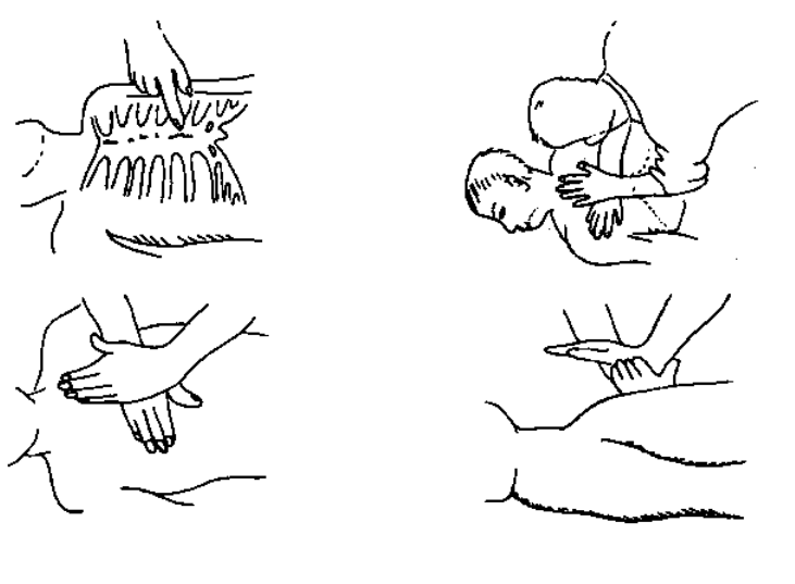
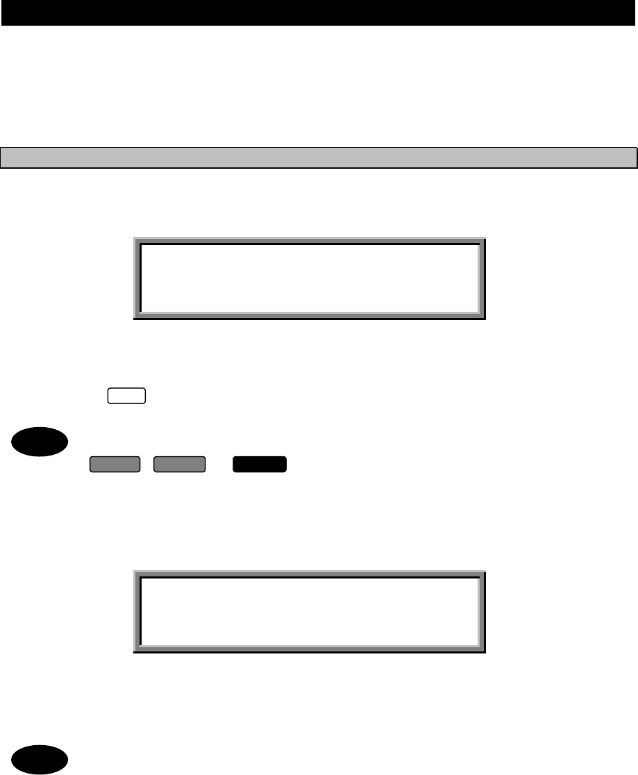
☆If the victim has a pulse but is not breathing
("Mouth to mouth" resuscitation) Figure 1.
(1) Place the victim's head facing backward (place something under the neck like a pillow).
(2) Point the chin upward to widen the trachea.
(3) Pinch the victim's nose, take a deep breath, then put your mouth over the victim's mouth and exhale
completely, making sure that your mouth completely covers the victim's mouth. Then remove your
mouth. Repeat this routine 10 to 15 times per minute (holding the nostrils).
(4) Pay attention to the victim to notice if he or she starts to breath. If breathing returns, stop
resuscitation.
(5) If it is impossible to open the victim's mouth, put something like a plastic straw or vinyl tube into one of
the nostrils then blow air in while covering the mouth and the other nostril.
(6) Occasionally, when the victim comes back to consciousness, they immediately try to stand up.
Prevent this and keep them in a laying position. Give them something warm to drink and be sure that
they rest (do not give them any alcohol).
Administering artificial respiration by raising the head.
①
①①
①(1) Raise the back of the head, then place one
hand on the forehead and place the other
hand under the neck. →①
→①→①
→①
Most victims open their mouth when doing this,
making "mouth to mouth" resuscitation easier.
②
②②
②(2) Cover the victim's mouth by opening your
mouth widely, then push your cheek against
the victim's nose, →②
→②→②
→②
or pinch the victim's nose to prevent air from
leaking out of it. →③
→③→③
→③
③
③③
③(3) Completely exhale into the lungs.
Exhale into the lungs until the chest is inflates.
You have to blow as rapidly as possible for the
first 10 times.
("Mouth to mouth" resuscitation) Figure 1.
iv
☆If the victim has no pulse and is not breathing
(Heart massage in combination with artificial respiration.) Figure 2
If the victim has no pulse, his or her pupils are dilated, and if you cannot detect a heartbeat, the heart may
have stopped, beginning artificial respiration is critical.
(1) Put both hands on the diaphragm, with hands on top of each other keeping both arms straight. (If your
elbows are bent, you cannot push with as much power.) Press the diaphragm with your body weight
until the chest sinks about 2 cm (about 50 times per minute).
(2) If administering first aid when alone:
Perform the heart massage about 15 times then blow in twice. Repeat this routine.
If administering first aid with two people:
One person performs the heart massage 5 times, and the other person blows air in once. Repeat this
routine. (Heart massage and "mouth to mouth" resuscitation used together.)
(3) Constantly check the pupils and the pulse, if the pupils become normal and the pulse steadies, keep
them in a laying position and give them something warm to drink, be sure that they rest (do not give
them any alcohol.). In any case you have to entrust major decision making to a doctor. Having
understanding people around is essential to the victim's recovery from the mental shock of
electrocution.
①
①①
①②
②②
②
③
③③
③④
④④
④
(Heart massage in combination with artificial respiration.) Figure 2

v
Preface
Thank you for purchasing JRC MF/HF Radio Equipment model JSS-296.
● For best operation and performance results, read this manual thoroughly before use.
● Keep this manual in a convenient place for future reference. Make use of this manual when
experiencing operation difficulties.
vi
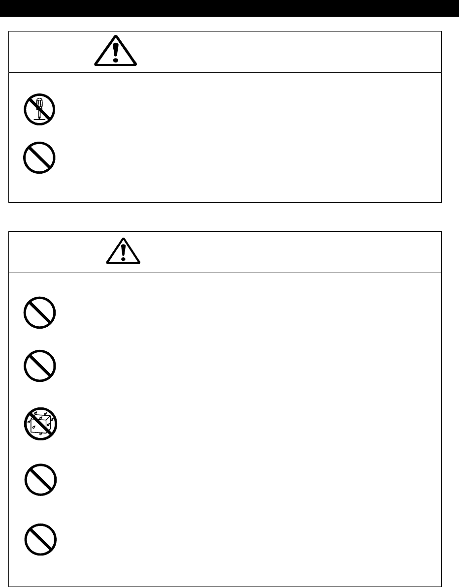
WARNING
Before Operation
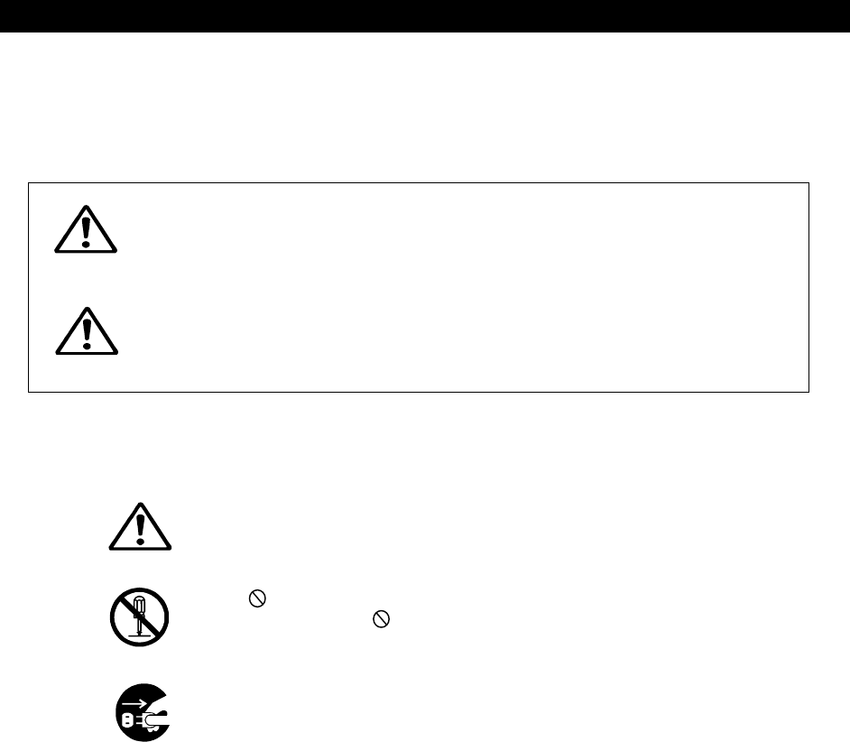
Concerning the symbols
This manual uses the following symbols to explain correct operation and to prevent injury or
damage to property. The symbols and descriptions are as follows. Understand them before
proceeding with reading this manual.
Indicates a warning that, if ignored,
may result in serious injury or even
death.
Indicates a caution that, if ignored,
may result in injury or damage to
property.
Examples of symbols
The △ symbol indicates caution (including DANGER and WARNING). The
illustration inside the △ symbol specifies the content of the caution more
accurately. (This example is a general caution.)
The symbol indicates that performing an action is prohibited. The illustration
inside or next to the symbol specifies the contents of the prohibited operation.
(In this example, disassembly is prohibited.)
The ● symbol indicates operations that must be performed. The illustration
inside the ● symbol specifies the obligatory operation. (In the example,
unplugging is the obligatory operation.)
Concerning warning labels
A warning label is pasted to the top cover of this product.
Do not remove, damage, or modify the label.
CAUTION

vii
Handling Precautions
WARNING
Do not disassemble or modify this unit. Doing so may cause fire, electric
al shock, or failure.
Do not use a voltage other than specified. Doing so may cause fire, elec
trical shock, or failure.
If you remove a unit, be sure to store it in a non-conductive bag. If you
wrap It up with materials such as aluminum foil, the back-up power suppl
y may Short circuit and the ICs may be damaged.
There are no user-serviceable parts inside this equipment. Inspection or
maintenance by unauthorized persons may result in fire or electric shock.
For inspection and maintenance, contact JRC or its authorized agents.
viii
Handling Precautions
CAUTION
Do not use this equipment in an environment other than that specified.
Doing so may cause failure or malfunction.
Do not turn the trimmer resistors or trimmer capacitors on the PCB unit (they are
preset at the factory). Doing so may cause failure or malfunction.
Do not install the equipment in a place near water or in one with excessive
humidity, steam, dust or soot. Doing so may cause fire, electric shock, or failure.
Do not get this equipment wet or spill any liquids on or near this equipment. Doing
so may cause electrical shock or failure.
Do not place this equipment anywhere vibration or impact is likely to occur. Doing
so may cause a failure or injury.
Do not place anything on top of this equipment. Doing so may cause fire or failure.
Leave installation of this equipment to JRC or our agents. Installation by an
unauthorized person may lead to malfunction.
Be sure to turn OFF the printer’s power when opening and closing the printer
cover.
Failure to comply could result in electrical shock, failure, or injury.
Just after printing, the temperature of the printing head is high.
Do not touch the printing head until the temperature goes down.
Doing so may cause a burn or an injury.
Do not touch any part of the cutter.
Doing so is potentially dangerous.
ix
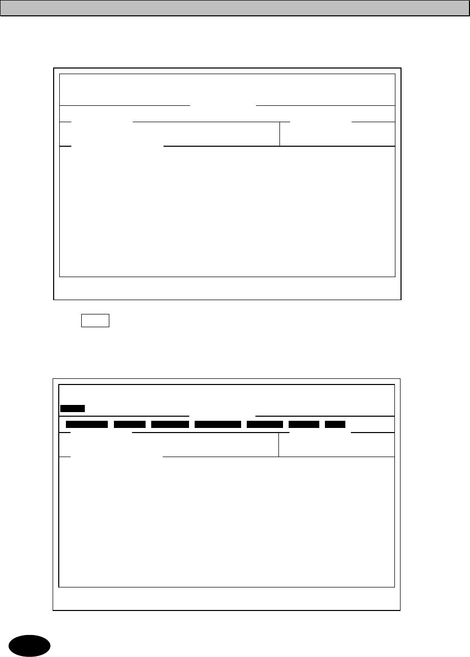
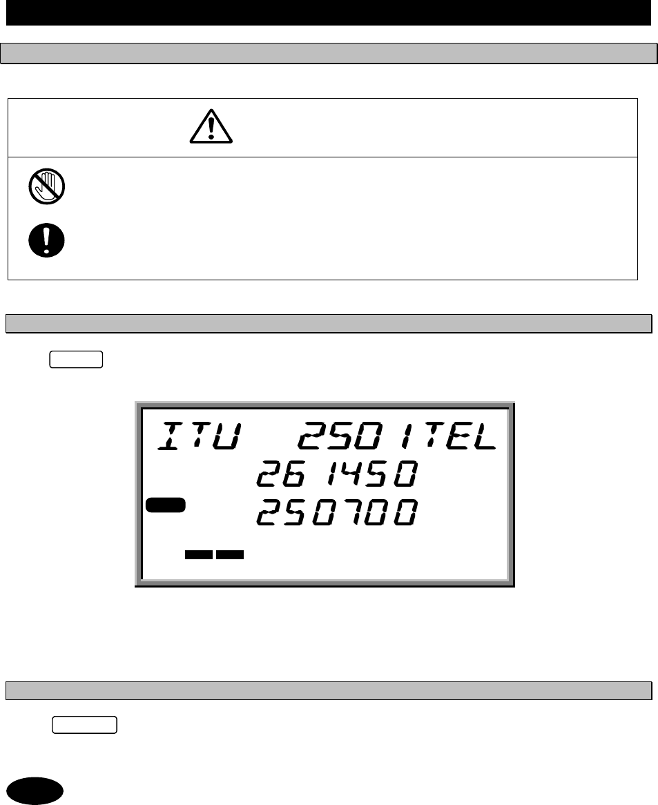
DISTRESS CALL Transmissible
Address : XXXXXXXXX
Nature : UNDESIGNATED DIST
Dist-position : 12゚34’N123゚45’E
Dist-UTC : 01:26
Dist-telecomm : J3E TEL
End of sequence: EOS
Call TX/RX freq: 2,187.5/ 2,187.5 kHz
D
DI
IS
ST
TR
RE
ES
SS
S
C
CA
AL
LL
LS
S
NCT-196N
There are three methods of transmitting a distress
call. These methods are described below in order
of ease of use, with the easiest first.
Transmitting Distress Calls 1
Procedure
1. Open the cover on the left and press .
The following screen is displayed.
•If stop the distress transmission, press .
2. Press for 3.5 seconds continuously.
• If stop the distress transmission, release .
3. The following screen is displayed and the distress transmission is started.
If a printer is connected, it prints out the distress message.
The distress message is transmitted for 5 times successively.
• If break the distress transmission, press .
STOP
DISTRESS CALL Transmitting
TX frequency : 2,187.5 kHz
TX date&time :06.Sep.2001(Thu) 01:26
1/ 5
Note
DISTRESS
DISTRESS
DISTRESS
Note
STOP
Note

x
4. When the distress transmission is completed, the screen is displayed as follows for a
few seconds.
5. The distress transmission is repeated at random intervals of 3.5 to 4.5 minutes.
On completion of the transmission, the screen is changed as follows. And the distress
transmission is repeated when the displayed time has counted down to zero.
DISTRESS CALL 2,187.5 kHz
NEXT DISTRESS CALL : AFTER 3.0 min
DISTRESS CALL Send Completed
TX frequency : 2,187.5 kHz
TX date&time :06.Sep.2001(Thu) 01:27
5/ 5
xi
DISTRESS CALL Transmissible
Address : XXXXXXXXX
Nature : UNDESIGNATED DIST
Dist-position : 12゚34’N123゚45’E
Dist-UTC : 01:26
Dist-telecomm : J3E TEL
End of sequence: EOS
Call TX/RX freq: 2,187.5/ 2,187.5 kHz
Transmitting Distress Calls 2
Front panel
Procedure
1. Press or .
2. Open the cover on the left and press
.
The following screen is displayed.
•If stop the distress transmission, press .
3. Press for 3.5 seconds at least.
• If stop the distress transmission, release .
4. The following screen is displayed and the distress transmission is started.
If a printer is connected, it prints out the distress message.
The distress message is transmitted for 5 times successively.
• If break the distress transmission, press .
DISTRESS
DISTRESSDISTRESS
DISTRESS
1st: PRESS TO VERIFY & EDIT MESSAGE
1st: PRESS TO VERIFY & EDIT MESSAGE1st: PRESS TO VERIFY & EDIT MESSAGE
1st: PRESS TO VERIFY & EDIT MESSAGE
2nd: PRESS & HOLD UNTIL BEEP SOUNDS
2nd: PRESS & HOLD UNTIL BEEP SOUNDS2nd: PRESS & HOLD UNTIL BEEP SOUNDS
2nd: PRESS & HOLD UNTIL BEEP SOUNDS
CONTINUOUSLY TO TRANSMIT
CONTINUOUSLY TO TRANSMIT CONTINUOUSLY TO TRANSMIT
CONTINUOUSLY TO TRANSMIT
DISTRESS
DISTRESSDISTRESS
DISTRESS
URGENCY
URGENCYURGENCY
URGENCY
OTHERS
OTHERSOTHERS
OTHERS
CLASS A DSC
CLASS A DSCCLASS A DSC
CLASS A DSC
2187.5kHz
2187.5kHz2187.5kHz
2187.5kHz
8414.5kHz
8414.5kHz8414.5kHz
8414.5kHz
STOP
STOPSTOP
STOP CALL
CALLCALL
CALL
ALM/CALL
ALM/CALLALM/CALL
ALM/CALL
2187.5kHz 8414.5kHz
DISTRESS CALL Transmitting
TX frequency : 2,187.5 kHz
TX date&time :06.Sep.2001(Thu) 01:26
1/ 5
Note
DISTRESS
DISTRESS
Note
STOP
Note
DISTRESS
STOP

xii
5. When the distress transmission is completed, the screen is displayed as follows for a
few seconds.
6. The distress transmission is repeated at random intervals of 3.5 to 4.5 minutes.
On completion of the transmission, the screen is changed as follows. And the distress transmission
is repeated when the displayed time has counted down to zero.
DISTRESS CALL 2,187.5 kHz
NEXT DISTRESS CALL : AFTER 3.0 min
DISTRESS CALL Send Completed
TX frequency : 2,187.5 kHz
TX date&time :06.Sep.2001(Thu) 01:27
5/ 5
xiii
Transmitting Distress Calls 3
The NCT-196N enables an operator to create and edit messages for transmission.
Procedure
1. Confirm that the "DSC watching" screen is displayed.
2. Press .
The "MENU #1-EDIT&CALL" screen is displayed.
3. Press
and then
to select “3. Distress call”.
The "Distress Call" screen is displayed as follows. Then setup these items except for “Address”
and “End of sequence” properly.
4. Open the cover on the left and press
for 3.5 seconds at least.
5. The following screen is displayed and the distress transmission is started.
If a printer is connected, it prints out the distress message.
The distress message is transmitted for 5 times successively.
• If break the distress transmission, press .
DSC watching 06.Sep.2001(Thu) 01:26
12゚34’N123゚45’E SPEED:12.4KT at 01:26
Self-ID = XXXXXXXXX [UTC]
MENU
MENU #1-EDIT&CALL Select no.
1.Individual call
2.Acknowledgement call
3.Distress call
4.Distress relay call
5.Auto/semi-auto call
6.All ships call Use and to scroll the screen.
7.Group call
8.Area call
9.Position request
10.Polling call
11.Test call
▲
▼
3ENT
DISTRESS CALL Transmissible
Address : XXXXXXXXX
Nature : UNDESIGNATED DIST
Dist-position : 31゚00’N 135゚00’E
Dist-UTC : 01:26
Dist-telecomm : J3E TEL Use and
to
End of sequence: EOS scroll the screen.
Call TX/RX freq: 2,187.5/ 2,187.5 kHz
▲
▼
DISTRESS CALL Transmitting
TX frequency : 2,187.5 kHz
TX date&time :06.Sep.2001(Thu) 01:26
1/ 5
DISTRESS
Note STOP
xiv
6. When the distress transmission is completed, the screen is displayed as follows for a
few seconds.
7. The distress transmission is repeated at random intervals of 3.5 to 4.5 minutes.
On completion of the transmission, the screen is changed as follows. And the distress transmission
is repeated when the displayed time has counted down to zero.
Receiving Distress Calls
When a distress call is received, the "DISTRESS/URGENCY" LED lights up in red and the alarm tone
sounds. Up to 20 received distress calls are automatically stored in memory for future confirmation.
The distress messages are automatically deleted 48 hours after they have been received in
order to prevent unnecessary distress message relay transmission. Thus the distress
messages more than 48 hours old cannot be displayed but it is a proper transaction.
DISTRESS CALL 2,187.5 kHz
NEXT DISTRESS CALL : AFTER 3.0 min
DISTRESS CALL Send Completed
TX frequency : 2,187.5 kHz
TX date&time :06.Sep.2001(Thu) 01:27
5/ 5
Note
When a distress call is received, inform the ship's captain or officer in charge and log the
distress call. There are legal repercussions if such a procedure is not followed.
Furthermore if a distress call is received, make contact immediately according to
"RECEPTION OF DSC DISTRESS ALERT ".
ATTENTION
xv
CONTENTS
CAUTIONS AGAINST HIGH VOLTAGE ..........................................................................i
Cautions concerning treatment of electrocution victims............................................i
First aid ..........................................................................................................................ii
Preface ...........................................................................................................................v
Before Operation ..........................................................................................................vi
Handling Precautions..................................................................................................vii
1. INTRODUCTION ..................................................................................................... 1-1
1.1 Outlines................................................................................................................................. 1-1
1.2 Features................................................................................................................................ 1-1
1.3 Configuration ........................................................................................................................ 1-2
1.4 External View........................................................................................................................ 1-4
1.5 Block Diagram ...................................................................................................................... 1-6
2. PART NAMES AND FUNCTIONS........................................................................... 2-1
3. OPERATIONS ......................................................................................................... 3-1
3.1 System Standby ................................................................................................................... 3-1
3.1.1 Turning the Power ON ......................................................................................................... 3-1
3.1.2 Turning the Power OFF ....................................................................................................... 3-1
3.2 Mode Change ....................................................................................................................... 3-2
3.2.1 Mode change to DSC .......................................................................................................... 3-2
3.2.2 Mode change to TLX ........................................................................................................... 3-3
3.3 Setting Position and Time Data ............................................................................................ 3-4
3.3.1 Setting the Internal Clock (DATA&TIME EDIT).................................................................... 3-4
3.3.2 Specifying Position Input (POSITION EDIT) ....................................................................... 3-6
3.4 Radiotelephone operations .................................................................................................. 3-7
3.4.1 Turning the Power ON/OFF ................................................................................................. 3-7
3.4.1.1 Turning the Power ON...................................................................................................... 3-7
3.4.1.2 Turning the Power OFF.................................................................................................... 3-7
3.4.2 Communication Procedure .................................................................................................. 3-8
3.4.2.1 Setting the channel number with the Jog Dial.................................................................. 3-8
3.4.2.2 Monitoring the transmissio frequency .............................................................................. 3-9
3.4.2.3 Setting the channel number with keypad ......................................................................... 3-9
3.4.2.4 Manually inputting frequency ......................................................................................... 3-10
3.4.2.5 Scanning reception .........................................................................................................3-11
3.4.3 Other Functio Settings ....................................................................................................... 3-12
3.4.3.1 Setting the communication mode................................................................................... 3-12
3.4.3.2 Setting the uotput power ................................................................................................ 3-13
3.4.3.3 Turning the Automatic Gain Control(AGC)ON ............................................................... 3-13
3.4.3.4 Adjusting squelch Level ................................................................................................. 3-14
3.4.3.5 Setting the scanning speed............................................................................................ 3-15
3.4.3.6 Registering the User channel......................................................................................... 3-15
3.4.3.7 Registering a channel group name ................................................................................ 3-17
3.4.3.8 Setting the meter indication mode.................................................................................. 3-18
3.4.3.9 Setting the Automatic Tuning Start(ATS) ....................................................................... 3-18
xvi
3.4.3.10 Setting the wait time for ATS .......................................................................................... 3-19
3.4.3.11 Turning the key-in sounds ON/OFF ............................................................................... 3-19
3.4.3.12 Setting the loudspeaker output ON/OFF........................................................................ 3-20
3.4.3.13 List of shortcut keys........................................................................................................ 3-21
3.5 DSC operations .................................................................................................................. 3-23
3.5.1 Menus and Modes ............................................................................................................. 3-23
3.5.2 Receiving Messages .......................................................................................................... 3-25
3.5.3 Sending Messages ............................................................................................................ 3-29
3.5.4 Other Functions.................................................................................................................. 3-63
3.6 NBDP operations................................................................................................................ 3-75
3.6.1 NBDP SettingsMenus and Modes ..................................................................................... 3-75
3.6.2 ARQ Communication ......................................................................................................... 3-77
3.6.3 FEC Communication..........................................................................................................3-81
3.6.3.1 SFEC Communication.................................................................................................... 3-81
3.6.3.2 CFEC Communication.................................................................................................... 3-83
3.6.4 Scanning for TLX mode ..................................................................................................... 3-85
3.6.4.1 Scanning start................................................................................................................. 3-85
3.6.4.2 Scanning stop................................................................................................................. 3-86
3.7 PA operations...................................................................................................................... 3-87
3.7.1 AC/DC power source voltage checking ............................................................................. 3-87
3.7.2 DC (Battery) charge/discharge current checking............................................................... 3-87
3.7.3 RF current of Antenna and PA checking ............................................................................ 3-88
3.7.4 PA voltage (Vc) and current (Ic) checking.......................................................................... 3-89
3.7.5 SWR of PA output checking ............................................................................................... 3-90
3.7.6 Beeping sound ON/OFF setting......................................................................................... 3-91
3.7.7 PA alarm sound ON/OFF setting........................................................................................ 3-91
3.7.8 Battery charge mode (Ordinary/Equal) setting .................................................................. 3-92
3.7.9 DC operation ...................................................................................................................... 3-92
3.8 Printer operations ............................................................................................................... 3-93
3.8.1 Names and Functions ........................................................................................................3-94
3.8.2 Operation Panel ................................................................................................................. 3-95
3.8.3 Opening/Closing the Printer Cover .................................................................................... 3-96
3.8.4 Replacing the Roll Paper ...................................................................................................3-98
3.8.5 Replacing the Ribbon Cassette Cartridge ....................................................................... 3-102
3.8.6 Adjusting the Printing Pressure (to Printing Paper Thickness)........................................ 3-104
3.8.7 Setting thd DIP Switch ..................................................................................................... 3-105
3.8.8 How to Attend to Error Detection ..................................................................................... 3-107
4. MAINTENANCE AND INSPECTION....................................................................... 4-1
4.1 General Maintenance and Inspection .................................................................................. 4-2
5. AFTER-SALES SERVICE ....................................................................................... 5-1
5.1 Before returning repair ......................................................................................................... 5-1
5.2 Periodical maintenance recommended................................................................................ 5-1
6. SPECIFICATIONS ................................................................................................... 6-1

xvii
Abbreviations
AM: Amplitude Modulation. The carrier amplitude is modulated in accordance with the
signal.
AMVER: Automated Mutual-assistance Vessel Rescue System
ARQ: Automatic Repeat Request
ASCII: American Standard Code for Information Interchange
ATS: Automatic Tuning Start
ATU: Antenna Tuner
AUTO TELEX: A kind of Telex communication. The line is automatically established by receiving a
free signal transmitted from a coast station.
CFEC: Collective Forward Error Correcting. A mode transmitting to many and unspecified
stations.
CIRM: Committee International Radio Maritime
COMSAR: Sub-committee on Radio Communications and Search and Rescue
DIM: Dimmer
DSC: Digital Selective Calling
DTE: Data Terminal Equipment
FEC: Forward Error Correction System
GMDSS: Global Maritime Distress and Safety System
GPS: Global Positioning System
HF: High Frequency
xviii
IMO: International Maritime Organization
ITU: International Telecommunication Union. Regulates the treaty and rules relating to the
telecommunication of wire, wireless, land wires, marine, air and space. As internal
machinery, there are WARC, CCIR, CCITT and others.
MF: Medium Frequency (300 kHz to 3 MHz)
NBDP: Narrow Band Direct Printing
NNSS: Navy Navigation Satellite System
PC: Personal Computer
RCC: Rescue Coordinate Center
RR: Radio Regulations
SAR: Search and Rescue
SFEC: Selective Forward Error Correcting. Destination is specified and transmitted in this
mode.
SOLAS: International Convention for the Safety of Life at Sea
SSB: Single Side Band
UTC: Universal Time Coordinated

1-1
1.
INTRODUCTION
1.1 Outlines
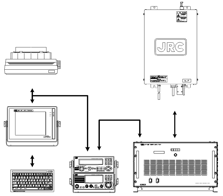
The JSS-296 MF/HF Radio Equipment is designed for vessels navigating A2, A3 and A4 sea areas. It consists
of mainly the JSB-196GM Radiotelephone, NFC-296 Antenna Tuning Unit (ATU), NCT-196N DSC/NBDP
MODEM, NDZ-127J Data Terminal Equipment (DTE), NDF-268 Keyboard, and NAH-692 Power Amplifier, and
it provides the optimum GMDSS system for the superior performance, compact, lightweight and highly efficient
design of the units, which ensures easy operation for distress and safety calling as well as general
communications.
1.2 Features
●
●●
●Fully Complies with GMDSS Requirements
All the functions required by IMO resolutions A.804 (19) and A.806 (19) are equipped, and suitable for radio
installations of vessels navigating A2, A3 and A4 sea areas.
●
●●
●Inadvertent Distress Alert Protection
The DISTRESS button is protected by a cover to prevent inadvertent distress alert transmission.
●
●●
●AC/DC Two-way Power Supply
The Power Supply equipped in the NAH-692 Power Amplifier is connected to both AC mains and auxiliary
DC24V battery, and can switch them automatically.
●
●●
●Selfcheck Function
A Built-in high grade selfcheck function centrally controlled using JSB-196GM Radiotelephone ensures easy
maintenance.
●
●●
●Built-in Dummy Load for ATU Selfcheck
The dummy load for checking the NFC-296 Antenna Tuning Unit (ATU) is built-in and not required to connect as
extra unit.
●
●●
●Outdoor Installable Antenna Tuning Unit
The NFC-296 Antenna Tuning Unit can be installed outdoors such as on deck, ensuring effective emission of
transmitter power.
1-2
1.3 Configuration
WARNING
Do not disassemble or modify this unit. Doing so may cause fire, electrical sh
ock, or failure.
Do not use a voltage other than specified. Doing so may cause fire, electrical
shock, or failure.
CAUTION
Do not use this equipment in an environment other than that specified.
Doing so may cause failure or malfunction.
Do not install the equipment in a place near water or in one with excessive humidity,
steam, dust or soot. Doing so may cause fire, electric shock, or failure.
Do not get this equipment wet or spill any liquids on or near this equipment. Doing so
may cause electrical shock or failure.
Do not place this equipment anywhere vibration or impact is likely to occur. Doing so
may cause a failure or injury.
Do not place anything on top of this equipment. Doing so may cause fire or failure.
1-3
NFC-296 ATU
NAH-692 Power AmplifierNCT-196N DSC/NBDP Modem
JSB-196GM Radiotele
p
hone
NDF-268 Keyboard
NDZ-127J DTE
NKG-800 Printer
1-4
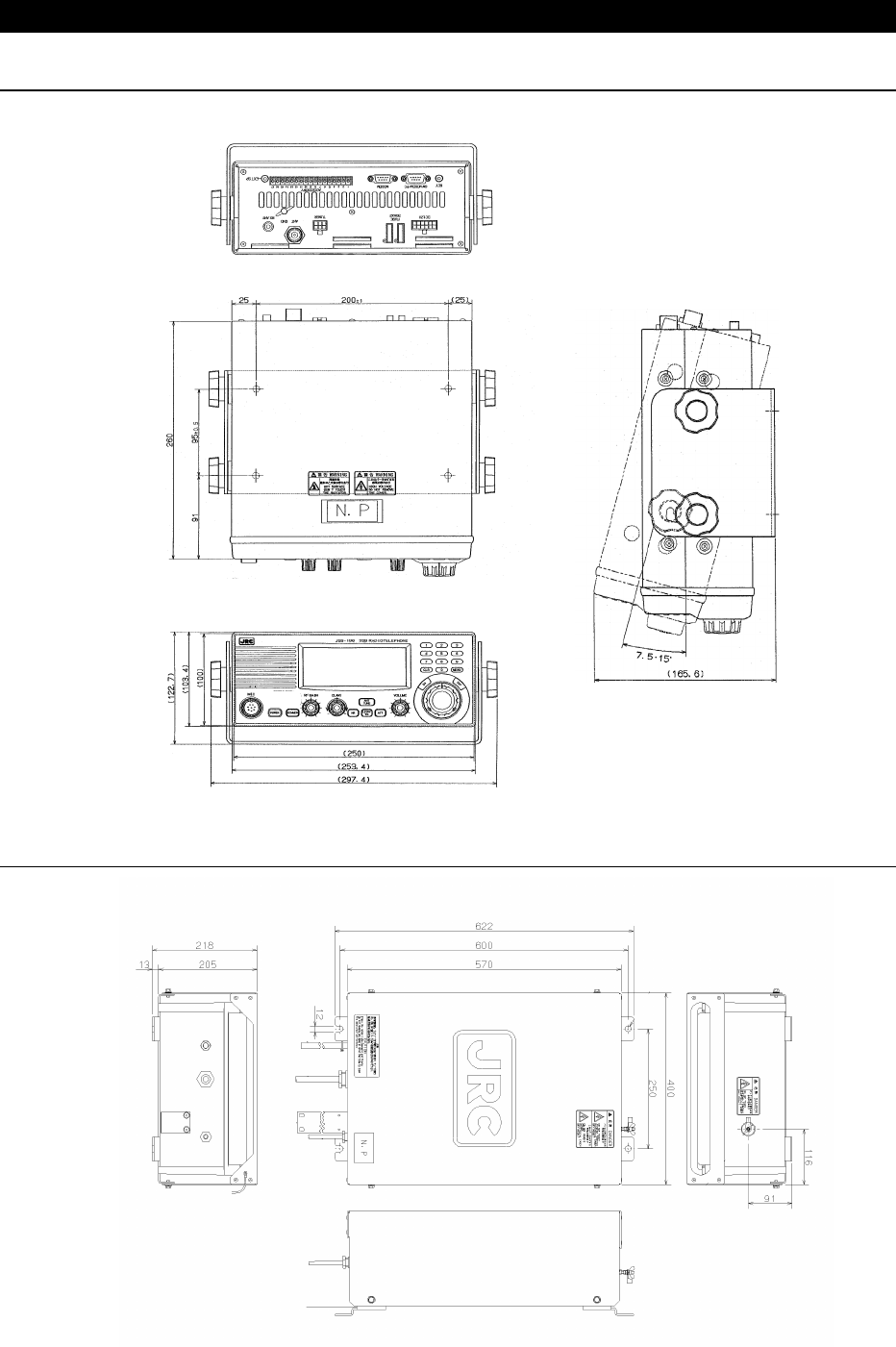
1.4 External View
●
●●
● JSB-196GM Radiotelephone
(Unit: mm)
●
●●
● NFC-296 Antenna Tuner
(Unit: mm)
1-5
●
●●
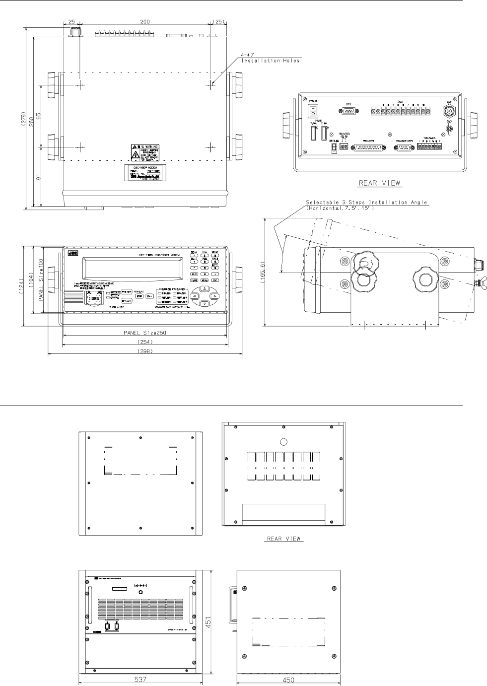
● NCT-196N DSC/NBDP Modem
(Unit: mm)
●
●●
● NAH-692 Power Amplifier
(Unit: mm)
1-6
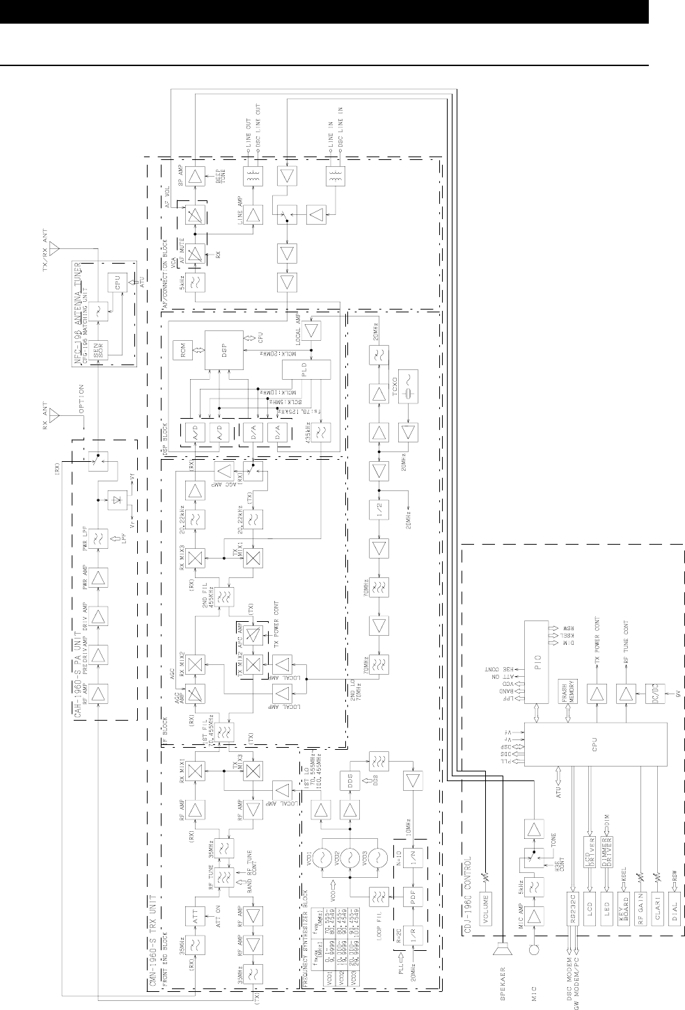
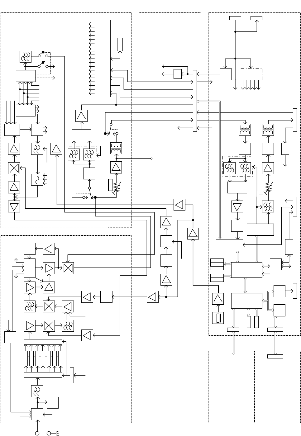
1.5 Block Diagram
●
●●
● JSB-196GM MF/HF Radio Equipment
1-7
●
●●
● NCT-196N DSC/NBDP Modem
BK
RELAY
ARRE-
STER
2.1875
4.2075
6.312
8.4145
12.577
16.8045
1.6 HPF
DIODE SWITCH
DIODE SWITCH
DECODER
AGC
AMP AGC
DET
BK
CONT
RF AMP
40.455M
RF AGC
IF AMP
455k IF AMP
IF AMP
IF AMP IF AMP
25M
LOCAL
AMP LOCAL
AMP
RF AGC S-AD
MUTE
×2
ALC
DET
DDS2DDS1
PFD
1/P
1/2 ×4
×5
FSTS
FSTEST
LINE LINE AMP
LN CONT
CPU
BLD
LLD
CLK2
DATA2
RFBAND
LNCONT
FSTEST
AGC OFF
MUTE
LE
LLD
SLD
DATA1
DATA2
CLK1
CLK2
FSTS
SCCLK
VCO1
QCK
S_AD
5V_CHK
LK
fDDS
VCO3
VCO2
LK
UNLOCK
QCK
VCO3
VCO2
VCO1
LPFVCO
LE
DATA1
CLK1
RFTEST RFTS(10kHz)
BFOCONT
RF BAND
1st LOCAL
42.6425∼
57.2595MHz
20MHz
40/50MHz
20MHz
-BKBKDRIVE
RF TEST
RFTS
790±85Hz
BFO
455.79kHz
(456.7kHz) SCCLK
EEPROM
ANT
E
MARK
SPACE
LCD UNIT
PANEL BOARD
CDT-1962
MOTHER BOARD
CQC-1962
W/K RF AMP
CAF-450
W/K CONTROL
CDJ-1701
PIO
J202J203
8255
J203
J201
LCD
PRINTER
PANEL
SUB
CPU
RAM
EPROM
DTCXO
20MHz
AF MONI
J2
-BK
LINE OUT
EXT LINE IN
DC OUT
DOT DET
DOT RESET
SERIAL
REG
+5V +12V
DET
SCCLK
MARK
SPACE
OUT LVL
LINE AMP
ATT
AGC
TB2
RS422NMEA
TRX/NMEA
MAIN
CPU
NMEA
TIMER
FS_DC
BIT
SYNC
I/O
J3
-BK
RS232C
BIT
SYNC
WR_SERIAL
TRX_SERIAL
TRANSCEIVER
WR_SERIAL-BK
REG
DC/DC
CONV.
+12V
+12V
+5V
+5V
+9V
-5V
-9V
J1TB1
PRN
PWR
POWER
SUPPLY
RAM1
EPROM1
RAM2
EEPROM
EPROM2
LINE OUT
LINE IN
40MHz CONT
CONTROL BOARD
CDJ-1999N
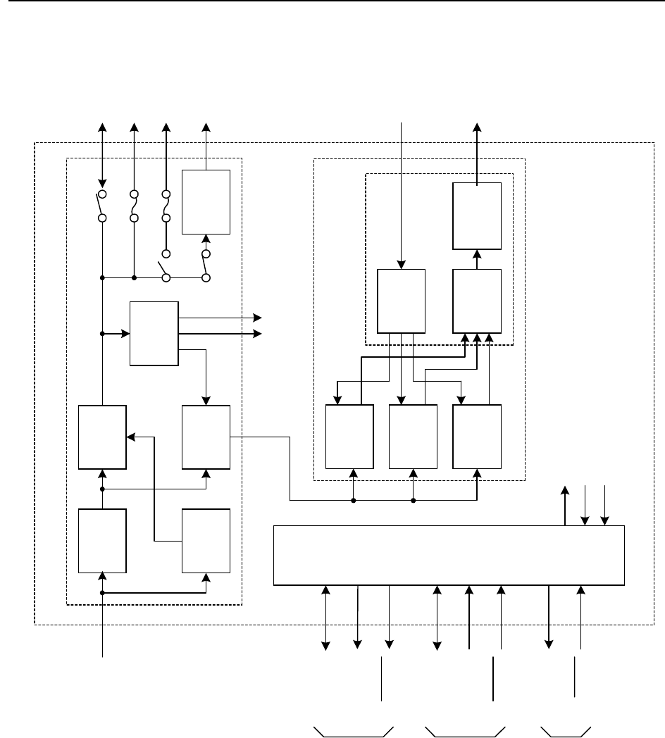
1-8
●
●●
● NAH-692 Power Amplifier
PFC DC24V
DC/DC 1
DC80V
DC/DC 2
DC13.6V
DC/DC 4
AC IN
PA(A)
(300W)
Spliter
Combiner Surge
Suppressor
RF OUT
to ATU
CONT
Serial
(TXD/RXD)
Analog value
PA_MUTE
Serial
(TXD/RXD)
PA_MUTE
+BK/-BK/RBK
TX_INH
JSB-196GM
Radiotelephone
NFC-196
ATU
External
Units
ANT CURR
PA/PS control
Analog value
Alarm
DC24V(Battery)
DC24V(VHF)
DC13.6V(JSB-196)
RF IN
from JSB-196
DC80V
DC26-30V
PS UNIT
NAH-296/596/896
PA UNIT
PA UNIT*
Note) JSS-296 needs PA(A) only.
Additionally JSS-596 needs PA(A) and PA(B), and
JSS-896 needs all of the PA modele (A to C).
DC24V(SES)
SES
or
MF/HF
DC12V
Sub-PS
DC24V
DC/DC 3
DC350V
DC12V
+BK/RBK
CONT
DC24V
DC24V
DC24V
PA(B)
(300W)
PA(C)
(300W)
NAH-692/695/698 PA UNIT
1-9
●
●●
● NFC-296 Antenna Tuning Unit
RF INPUT to Antenna
L0∼L8
Ci0
∼Ci8
L9
Cp
Matching sensor
CPU
PIO Driver
I/F
Serial
TXD
SWR_VF
L_PHASE
SWR_VR
LOW_R (Impedance < 50 ohm)
Serial
RXD
Co0
∼Co6
Cs
ANT
CURR
sensor
UNIT_A
Temperature
detection
Reset
E
+12V
E
ANT_CURR
9
9
7
30
A/D
A/D
JSB-196GM
Radiotelephone
Co_on
HI_TEMP (inside > 70deg)
TEMP
PCB ID
UNIT_B
Dummy
(50ohm)
FROM
A/D
TRNS
PA MUTE
2-1
2.
PART NAMES AND FUNCTIONS
●
●●
● JSB-196GM Radio Equipment
Operation Panel
MIC Connector
Fuse 40A
Fuse 40A
Rx Antenna In
p
ut
Ground Terminal
Ground Terminal
External Speaker Output
ATU Control Output
A
ccessor
y
Terminal
NCT-196N DSC/NBDP Modem
GLOBE E-mail (option) / PC
Telegraph Key Jack
13.6VDC Power Source Input
PTT Switch
NQW-213
Hand Set
2-2
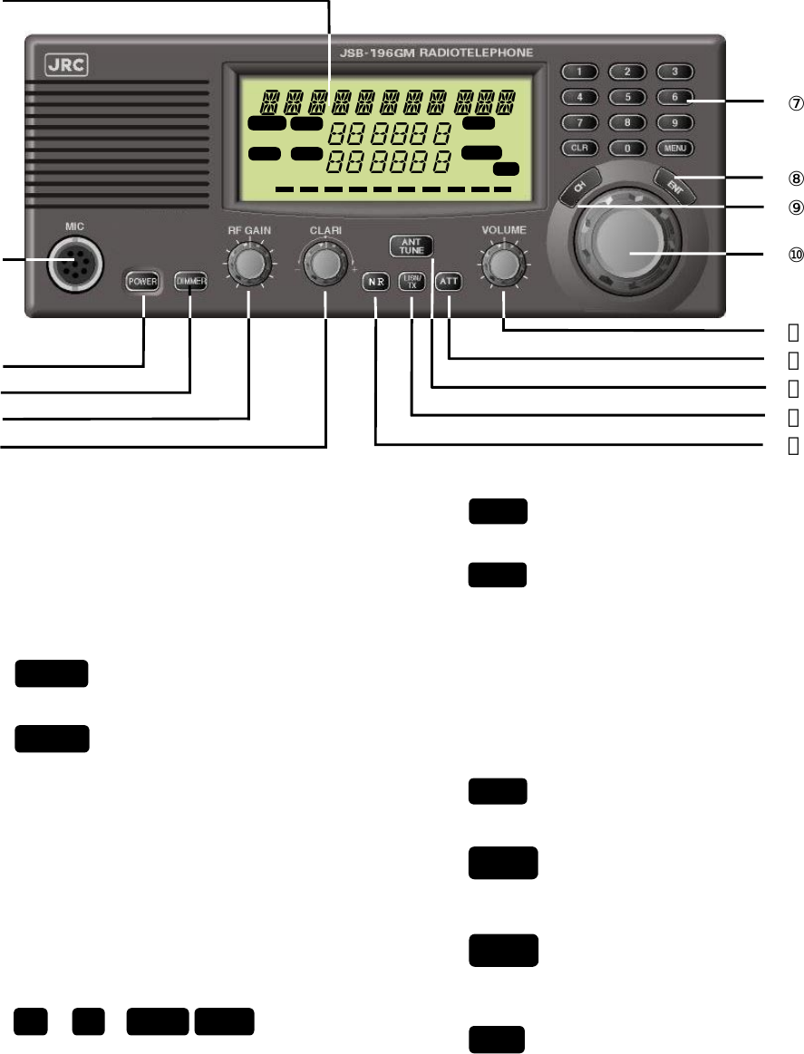
①
②
③
④
⑤
⑥
①
①①
①
Liquid Crystal Display Panel
②
②②
②
MIC
Connects the hand microphone or
handset.
③
③③
③
Turns power ON or OFF.
④
④④
④
Controls the brightness of the LCD.
⑤
⑤⑤
⑤
RF GAIN
Controls the RF gain.
⑥
⑥⑥
⑥
CLARI
Adjusts the frequency variation, which
ranges from –200 to +200Hz in 1Hz
steps.
⑦
⑦⑦
⑦
∼ ,
These buttons are used to input
frequency/channel values or to set a menu.
⑧
⑧⑧
⑧
Enters the input information.
⑨
⑨⑨
⑨
Starts channel selection.
⑩
⑩⑩
⑩
Jog Dial
Used to select a channel or receive
frequency or to select a menu.
⑪
⑪⑪
⑪
VOLUME
Controls the sound volume of reception.
⑫
⑫⑫
⑫
Turns the attenuator ON or OFF.
⑬
⑬⑬
⑬
Starts antenna tuning.
⑭
⑭⑭
⑭
Temporarily monitors the transmission
frequency in the Semi-Duplex mode
⑮
⑮⑮
⑮
Reduces pulsating noises.
POWER
DIMMER
NR
LISN/
TX
ATT
CLRMENU
90
ANT
TUNE
CH
ENT
1 2 3 4 5A
,
.
,
.
SCAN
SQ
L
RX FREQ
RDY
TX
TX FREQ
TUNE
ATT
NR
kHz AGC
kHz L
O
MODE 2 1 8 2
COMPASS SAFE DISTANCE 1.5m
2-3
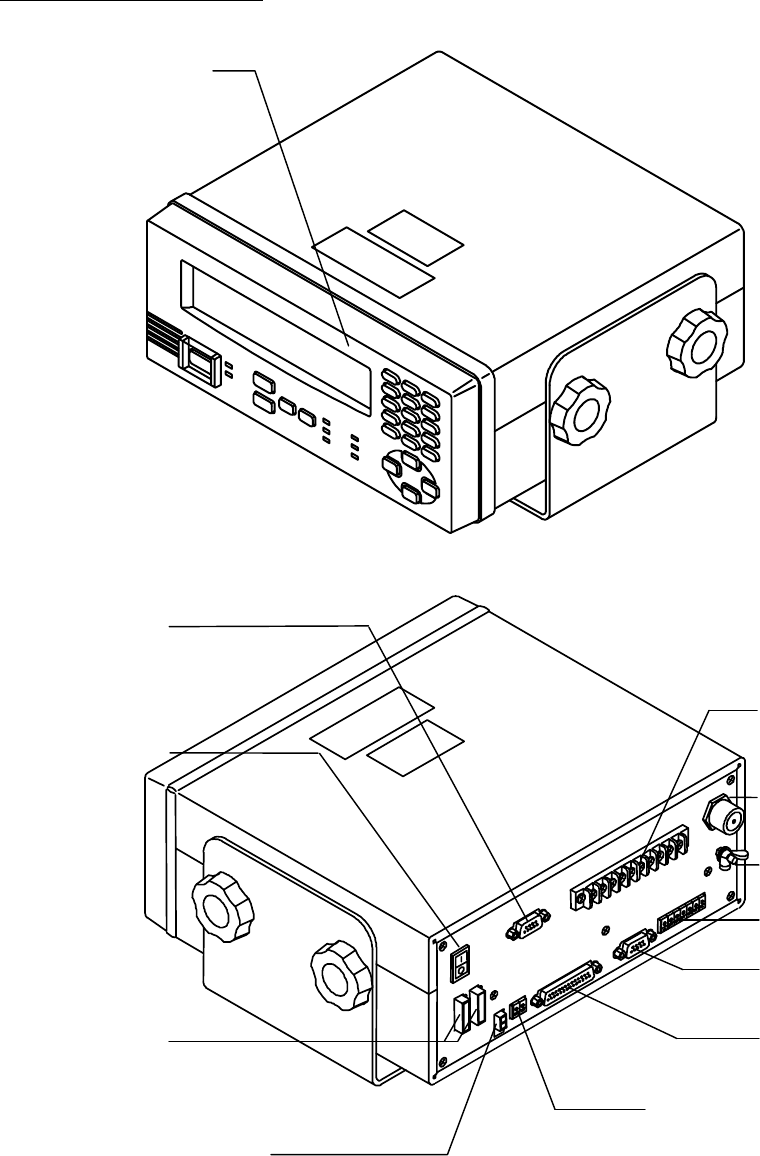
●
●●
●NCT-196N
NCT-196NNCT-196N
NCT-196N
DSC/NBDP
DSC/NBDPDSC/NBDP
DSC/NBDP Modem
Modem Modem
Modem
Operation Panel
DTE Terminal
Fuse 7.5A
13.6VDC Power Source Input
DMC Terminal
Ground Terminal
TRX/NMEA Terminal
JSB-196/196GM Terminal
Printer Terminal
Printer
13.6VDC Power Output Terminal
Rx Antenna Input
Power Switch
2-4
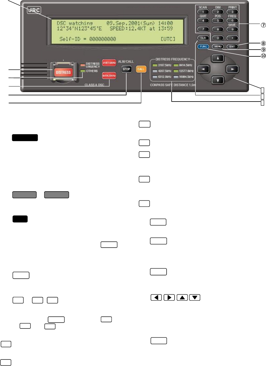
①
②
③
④
⑤
⑥
① Liquid Crystal Display (LCD) Panel
② Sends a distress call.
③ Transmit/Receive lamp
Red: Lights when a distress or emergency
call is being sent or received.
Green : Lights when a normal call is being
sent or received.
④ ,
Sets the JSB-196/196GM to the designated
frequency and F1B mode.
⑤
・ Stops the call if pressed while a call is being sent.
・ Turns off the alarm lamp and cancels the buzzer if
pressed when a call is being received.
・ If you press this key followed by the , the
software version is displayed and the set navigation
aid/radio equipment is momentarily displayed. (This
is not the initial setting process.)
⑥ Press after editing a message to start
Transmission of the message.
⑦ to ,
・ When editing, these keys enter the indicated
numbers.
・ If you press the key followed by
to and , the following operations are
performed:
SCAN: Alternately starts and stops scanning
when using the JSB-196/196GM to scan
the receive frequencies.
DIM Adjusts the LCD and key brightness in
four steps.
PRINT: Prints the current mode operations. In
"DSC watching" mode, this key selects
"PRINTMENU."
QUIT: Quits editing and returns to the higher
mode (MENU, etc.).
POS: When selecting "WORK FREQUENCY"
and "POSITION" when editing a
message, this key switches to
"POSITION".
FREQ: When selecting "WORK FREQUENCY"
and "POSITION" when editing a
message, this key switches to "WORK
FREQUENCY".
SAVE: Saves edited data and returns to the
higher mode (MENU, etc.).
⑧
Enters key input and selected items.
⑨
When pressed in "DSC watching" mode, the
screen switches from "MENU#1" to "MENU#2"
to "DSC watching", in that order.
⑩
Press this key to select the functions indicated in
blue.
⑪
Horizontal: Use to selectively display received
messages and to select the
contents when editing messages.
Vertical: Use to scroll the display and to
move the screen pointer vertically.
⑫
・ Deletes data that has been keyed in.
・ Enters the initial value when entering "POSITION"
or "WORK FREQUENCY."
⑬ Watch-keeping receiver channel
Lights the channel scanned by the watch-
keeping receiver. 2187.5kHz and 8414.5kHz are
fixed and cannot be switched.
1st: PRESS TO VERIFY & EDIT MESSAGE
1st: PRESS TO VERIFY & EDIT MESSAGE1st: PRESS TO VERIFY & EDIT MESSAGE
1st: PRESS TO VERIFY & EDIT MESSAGE
2nd: PRESS & HOLD UNTIL BEEP SOUNDS
2nd: PRESS & HOLD UNTIL BEEP SOUNDS2nd: PRESS & HOLD UNTIL BEEP SOUNDS
2nd: PRESS & HOLD UNTIL BEEP SOUNDS
CONTINUOUSLY TO TRANSMIT
CONTINUOUSLY TO TRANSMIT CONTINUOUSLY TO TRANSMIT
CONTINUOUSLY TO TRANSMIT
5
DISTRESS
6
9
2187.5kHz 8414.5kHz
ENT
MENU
STOP
FUNC
FUNC
CALL
9
0.
CLR
FUNC
1
11
1
9
6
1
2
3
4
NCT-196N DSC/NBDP MODEM
2-5
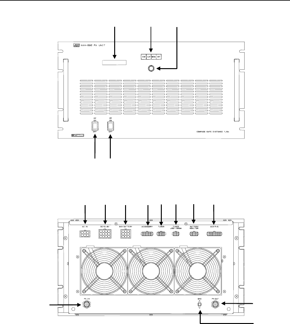
●
●●
● NAH-692 Power Amplifier
①②③
④⑤
⑥⑦⑧ ⑨⑩ ⑪⑫ ⑬
⑭⑮
⑯
2-6
①
①①
①
Liquid Crystal Display (LCD) Panel
Display for menu mode or selected meter value
②
②②
②
Menu Buttons
・ DIM: Dimmer control switch (High/ Medium/ Low)
・ CLR: Clear button for menu selection or alarm sound
・ MENU: MENU mode setting button
・ ENT: Selected menu or parameter entry button
③
③③
③
Menu Dial
Adjust the LCD contrast and select the menu items
④
④④
④
AC Power Switch
⑤
⑤⑤
⑤
DC Power Switch
⑥
⑥⑥
⑥
AC IN
AC100V~240V mains connector
⑦
⑦⑦
⑦
DC13.6V
DC13.6V power source output connector for JSB-196GM/NCT-196N
⑧
⑧⑧
⑧
24V BATTERY
DC24V power source input connector
⑨
⑨⑨
⑨
ACCESSORY
Peripherals (+/-BK, SES, ANT Changer, etc) control signal connector
⑩
⑩⑩
⑩
TUNER
Tuning control signal connector (to NFC-296 ATU)
⑪
⑪⑪
⑪
TUNER/JSB-196GM
Tuning control signal connector (from JSB-196GM Radiotelephone)
⑫
⑫⑫
⑫
BATTERY MONITOR
Battery and charger status monitor output connector
⑬
⑬⑬
⑬
AUX P/S
DC24V power source output connector (for SES, VHF, etc)
⑭
⑭⑭
⑭
PA IN
RF input connector (from JSB-196GM Radiotelephone)
⑮
⑮⑮
⑮
PA OUT
RF output connector (to NFC-296 ATU)
⑯
⑯⑯
⑯
GND
2-7
3-1
3.
OPERATIONS
This chapter describes mainly the way to use the JSS-296.
3.1 System Standby
3.1.1 Turning the Power ON
1. Turn on the AC and DC switches of NAH-692 Power Amplifier.
The other components except for JSB-196GM Radiotelephone are turned ON
simultaneously. After that the LCD on the front panel of the NAH-692 Power Amplifier
shows as follows.
AC Volt 221V
DC Volt 24.2V
2. Turn on the POWER switch of JSB-196GM Radiotelephone. (Note that it is
necessary to keep the POWER switch press for 1 sec at least to turn it on.)
Keep the NCT-196N DSC/NBDP Modem power switch turn ON because of the
obligation to watchkeep 24 hours a day while at sea.
3.1.2 Turning the Power OFF
1.
1.1.
1. Turn off the AC and DC switches of NAH-692 Power Amplifier.
Turn off the AC and DC switches of NAH-692 Power Amplifier.Turn off the AC and DC switches of NAH-692 Power Amplifier.
Turn off the AC and DC switches of NAH-692 Power Amplifier.
The other components including NCT-196N DSC/NBDP Modem are turned
OFF simultaneously. Therefore don’t turn OFF the switches while at sea
because of the obligation to watchkeep 24 hours a day.
Regarding the JSB-196GM Radiotelephone or NCT-196N DSC/NBDP Modem operations in detail,
see the specialized instruction manuals for them respectively.
ATTENTION
Note
Note
3-2
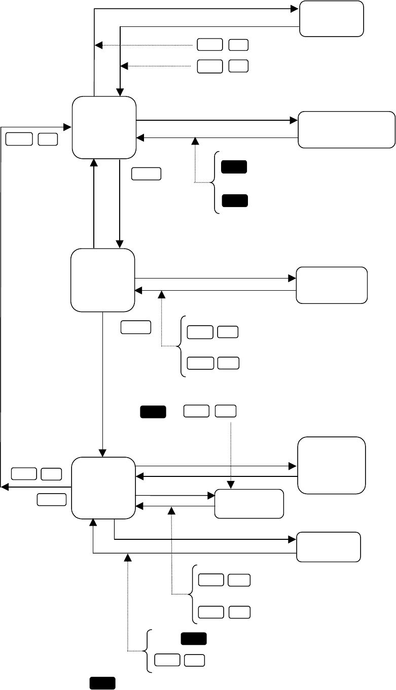
3.2 MODEM MODE Change
After turning ON the system, according to the mode setting when the system was turned OFF last,
the NCT-196N selects the mode. However if needed to change the mode, operate the system in
accordance with the following procedure.
3.2.1 MODE change to DSC
1. Confirm that the NCT-196N displays the following screen.
2. Press on the panel of the NCT-196N.
It is also available to press the keys concerning to Distress
( , , or ) .
3. After the mode change completed, the following initial display appears.
The mode of the peripheral units such as JSB-196/196GM Radiotelephone and NDZ-
127J DTE is changed to DSC mode simultaneously by the above-mentioned
operation.
DSC watching 06.Sep.2001(Thu) 01:26
12゚34’N123゚45’E SPEED:12.4KT at 01:26
Self-ID = XXXXXXXXX [UTC]
ENT
Note
DISTRESS
2187.5kHz 8414.5kHz
DSC watching 06.Sep.2001(Thu) 01:26
--------------------------------------------
MODE: XXXX (Press ENT to set DSC mode.)
--------------------------------------------
Note
3-3
3.2.2 MODE change to TLX
1. Confirm that the NDZ-127J displays the following screen in any mode except for TLX.
2. Press Enter on the NDF-268 Keyboard.
3. After the mode change completed, the following initial display appears.
The mode of the peripheral units such as JSB-196/196GM and NCT-196N is changed
to TLX mode simultaneously by the above-mentioned operation.
Note
[TLX] Tx=12345.6kHz / Rx=12345.6kHz (ITU CH= 0) 10-APR-2002 12:00(LT)
Loc: N19.00 E115.30 at 11:00(UTC)
File Mode Connect Service System Help
[ STATUS INFO ]
Scanning info Tuner/Tx.POWER
[No scanning] TUNER :[READY]
Tx.POWER:[FULL]
Last status messages
Move the cursor to the item you want with ↑,↓,→,← then press Enter
ST-BY
File
[xxx] Tx=12345.6kHz / Rx=12345.6kHz (ITU CH= 0) 10-APR-2002 12:00(LT)
Loc: N19.00 E115.30 at 11:00(UTC)
File Mode Connect Service System Help
[ STATUS INFO ]
Scanning info Tuner/Tx.POWER
[No scanning] TUNER :[READY]
Tx.POWER:[FULL]
Last status messages
Press Enter key to set NBDP mode...
Move the cursor to the item you want with ↑,↓,→,← then press Enter
3-4
3.3 Setting Position and Time Data
3.3.1 Setting the Internal Clock(DATE & TIME EDIT)
The built-in clock of the NCT-196N can be set the date (year, month, and day) and time manually. However if the
NCT-196N is connected to a navigation aid, the manual input data is overwritten because the navigation aid has
priority over the NCT-196N internal clock. The standard time is UTC but it is possible to input time difference from
the UTC and display the current local time (LT). Note that in case of no navigation aid connecting, time data should
be set to the present time manually and periodically because the time data input manually is treated as invalid data
and deleted after 23.5 hours past.
Procedure
1. Check that the "DSC watching" screen is displayed.
If the "DSC watching" screen is not displayed, press 3 times in succession to switch to the
"DSC watching" screen.
On the screen mark is displayed when no printer is connected to the NCT-196N.
2. Press
.
The "MENU#1-EDIT&CALL" screen is displayed.
STOP
MENU
DSC watching 06.Sep.2001(Thu) 01:26 P
12゚34’N123゚45’E SPEED:12.4KT at 01:26
Self-ID = XXXXXXXXX [UTC]
MENU #1-EDIT&CALL Select no.
1.Individual call
2.Acknowledgement call
3.Distress call
4.Distress relay call
5.Auto/semi-auto call
6.All ships call Use and to scroll.
7.Group call
8.Area call
9.Position request
10.Polling call
11.Test call
▼
▲
P
Note
If the position and time data from navigation aids such as a GPS receiver stop for more than 5 minutes,
or if it past for more than 4 hours without further input after entering position and time data manually, the
NCT-196N sounds alarm. When the alarm sounding in condition of navigation aid connecting, check
the navigation aid or the connections to the NCT-196N. Or when the alarm sounding in condition of no
navigation aid connecting, enter the new position and time data manually.
ATTENTION
3-5
Use and to scroll.
3. Press
again.
The "MENU#2-READOUT&SETUP" screen is displayed.
4. Press
, and then press
.
The "SETUP" screen is displayed.
5. From the "SETUP" screen, press
, and then press
.
The "DATE&TIME EDIT" screen is displayed.
6. Enter the respective settings.
・When the display time is set to "LT", enter the difference to the UTC in the "Time difference" item.
・Use the cursor keys ( and ) to switch between "+/-" for the "Time difference" and between
"UTC/LT" for the "Display time".
7. On completion of entering the data, press
, and then press
(SAVE).
Operation returns to the "SETUP" screen.
If you press , and then press (QUIT), the settings are discarded.
1ENT
DATE&TIME EDIT
Date (dd:mm:yy):06.05.00
Time (hh:mm) :19:23
Time difference:-05:00
Display time :UTC Use and to scroll.
▲
▼
9
FUNC
FUNC 4
MENU
3ENT
SETUP Select no.
1.Date&time edit
2.Position edit
3.Calling frequency registration
4.Address registration
5.Distress setup Use and to scroll.
6.Others alarm setup
7.Automatic acknowledgement setup
8.Scanning setup
9.Watchkeeping receiver setup
▲
▼
MENU #2 -READOUT&SETUP Select no.
1.Received distress message readout
2.Received others message readout
3.Setup
4.Self test
▲
▼
Note
3-6
3.3.2 Specifying Position Input (POSITION EDIT)
This operation enters the ship's position data manually. However if the NCT-196N is connected to a navigation aid,
which inputs the date and time data, the data from the navigation aid overwrite this position data input manually
because the navigation aid has priority over the NCT-196N. The position data is used in the distress file when
pressing the DISTRESS button, in the automatic acknowledgement files and as the initial value when editing
messages. For the "SETUP" screen, please see Section 3.3.1, " Setting the Internal Clock (DATE&TIME EDIT)",
steps 1 to 4. Note that in case of no navigation aid connecting, the position data should be set manually and
periodically because it is treated as invalid and deleted after 23.5 hours past.
Procedure
1. From the "SETUP" screen, press
and then press
.
The "POSITION EDIT" screen is displayed.
2. Enter the ship's position.
・Use the cursor keys ( and ) to switch between "NE", "NW", "SE", and "SW".
3. On completion of entering the data, press
, and then press
(SAVE).
Operation returns to the "SETUP" screen.
If you press , and then press (QUIT), the settings are discarded.
ENT
POSITION EDIT
Position Data: 12゚34’N123゚45’E
9
FUNC
FUNC 4
2
Note
3-7
3.4 Radiotelephone operations
3.4.1 Turning the Power ON / OFF
CAUTION
Never touch the antenna terminal, grounding terminal or counterpoise when the
JSB-196GM is turned ON. Doing so, may cause electrical shock.
Place Antenna Tuner NFC-196, antenna and counterpoise in position where no one
touches them. Doing not so, may cause electrical shock.
3.4.1.1 Turning the Power ON
Press on the front panel until the channel and frequencies are displayed as follows:
Figure 5.1 Initial display on the LCD (immediately after the equipment is powered on)
3.4.1.2 Turning the Power OFF
Press until LCD disappears.
The latest frequency and set-up state information such as communication mode are
stored in memory when the equipment is turned OFF. It will be set automatically when
the equipment is powered on again except the following items and these items will be
set to as follows:
⋅ Built-in loudspeaker ON/OFF (ON as default)
⋅ Squelch value (0 as default)
POWER
POWER
Note
RX FREQ
,
,,
,
.
..
.
KHz
TX FREQ
,
,,
,
.
..
.
KHz
NR
AGC
RDY
3-8
3.4.2 Communication Procedure
The JSB-196GM employs the Jog Dial for simply setting or selection for principal functions such as
TX/RX frequency, communication mode, output power, squelch, AGC, etc. and the following
procedures are provided for pleasant communication.
3.4.2.1 Setting the channel number with the Jog Dial
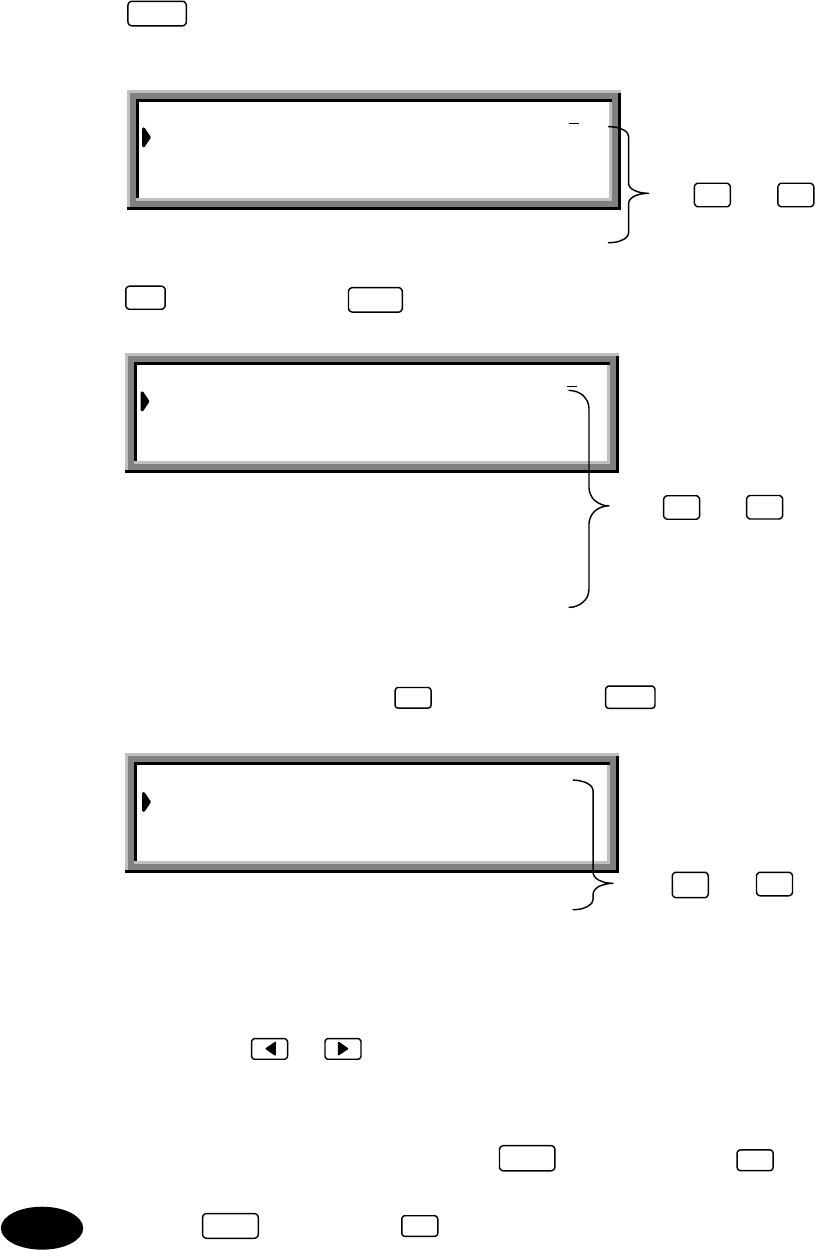
User channels can be set with the Jog Dial.
Procedure Examples of display on the LCD
Example of user channel number 101
1. Press .
Group number appears in the channel field
of the LCD.
(in the TEL mode)
2. Turn the Jog Dial. (*1)
Turn the Jog Dial until the group number,
ex. ”GROUP 6 TEL”, including the objective
channel number is displayed.
3. Press .
User channel number is displayed.
4. Turn the Jog Dial again until the objective
number, ”USR-101” is displayed and
complete setting.
If is blinking, press .
lights steadily during tuning, and
disappear when tuning is completed.
5. With these steps, the JSB-196GM is ready
to communicate. Start communication by
pressing PTT on the hand set.
*1 For easy selection of a channel number, you can allocate an identification label to
each channel (See "5.3.6 Registering a user channel").
CH
Note
ANT
TUNE
RX FREQ KHz
TX FREQ KHz
TUNE
NB
AGC
RDY
,
,,
, .
..
.
,
,,
, .
..
.
RDY
RX FREQ KHz
TX FREQ KHz
TUNE
NR
A
GC
RDY
,
,,
, .
..
.
,
,,
, .
..
.
TUNE
TUNE
ENT
3-9
3.4.2.2 Monitoring the transmission frequency
In semi-duplex mode the TX/RX frequency are set differently , though only one way transmission or
reception is possible at the same time. The transmission frequency signal can be checked for
interference.
Procedure
1. Press .
JSB-196 starts to receive TX frequency. After the check, press again or transmit to
return to the initial state.
3.4.2.3 Setting the channel number with keypad
User channel number can be set with keypad as follows.
Procedure Examples of display on the LCD
Example of user channel number 101 (RX
frequency 26145.0 kHz / TX frequency
25070.0 kHz).
1. Press .
"GROUP 1 TEL" appears in the channel
field of the LCD.
(in the TEL mode)
2. Press , and .
The channel number is displayed in the
channel field of the LCD.
User channel number: 1 to 200
ITU channel number:
TEL: 401 to 2517 CW : 401 to 2524
TLX: 401 to 2571 DSC: 401 to 2503
3. Press .
The input channel number is fixed.
4. Input the RX/TX frequency.
See the
「4.3.3.6 Registering the user channel
step 4∼7」.
5. If is blinking, press .
lights steadily during tuning, and
disappear when tuning is completed.
6. With these steps, the JSB-196GM is ready
to communicate. Start communication by
pressing PTT on the Hand set.
At channel setting, current mode must not be DSC mode.
CH
0 1
ENT
ANT
TUNE
TUNE
TUNE
RX FREQ KHz
TX FREQ KHz
TUNE
NB
AGC
RDY
,
, ,
, .
. .
.
,
, ,
, .
. .
.
RDY
RX FREQ KHz
TX FREQ KHz
TUNE
NR
AGC
RDY
,
,,
, .
..
.
,
,,
, .
..
.
LISN/
TX
LISN/
TX
1
Note
Note
3-10
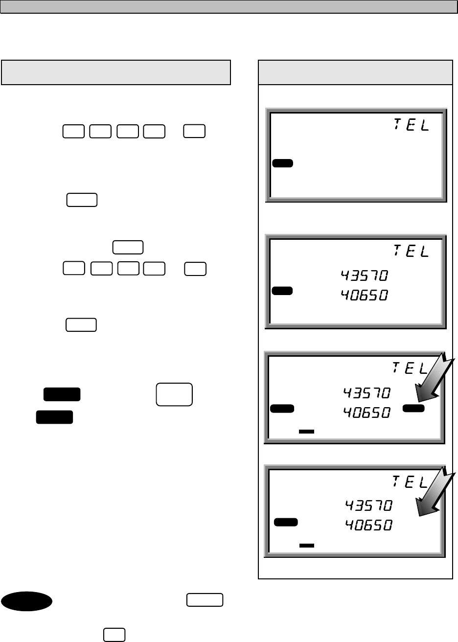
3.4.2.4 Manually inputting frequency
In this case, communication mode must be set in advance(For setting of a radio mode, see "5.3.1
setting a communication mode").TX and RX frequency can be set with keypad as follows.
Procedure Examples of display on the LCD
Example of RX frequency 4357.0 kHz / TX
frequency 4065.0 kHz .
1. Press , , , and for
the RX frequency. The RX frequency is
displayed in the channel field of the LCD.
2. Press .
The RX frequency is fixed. When you want
to use this frequency also as a TX
frequency, press again.
(in the TEL mode)
3. Press , , , and for
the TX frequency. The TX frequency is
displayed in the channel field of the LCD.
4. Press .
The TX frequency is fixed.
5. If r is blinking, press .
lights steadily during tuning, and
disappear when tuning is complete.
6. With these steps, the JSB-196GM is ready
to communicate. Start communication by
pressing PTT on the Hand set.
• Press two or three times , enable to change the RX/TX frequency
individually.
• Press to change the DISTRESS frequency 2,182.0 kHz.
4 3 5 70
40650
ENT
ANT
TUNE
TUNE
TUNE
ENT
RX FREQ KHz
TX FREQ KHz
NR
AGC
RDY
RX FREQ KHz
TX FREQ KHz
NR
AGC
,
,,
, .
..
.
,
,,
, .
..
.
RDY
RX FREQ KHz
TX FREQ KHz
NB
AGC
TUNE
,
,,
, .
..
.
,
,,
, .
..
.
RDY
RX FREQ KHz
TX FREQ KHz
RDY TUNE
NR
AGC
,
,,
, .
..
.
,
,,
, .
..
.
ENT
CH
Note
0
3-11
3.4.2.5 Scanning reception
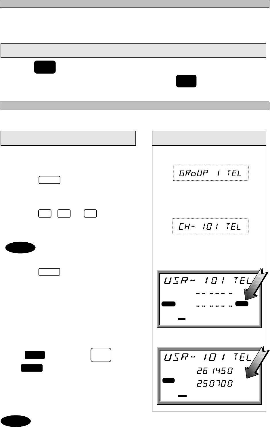
The reception frequency stored in user channel group 1 to 10, each 20 channels can be scanned.
You can select a desired group (20 user channels per group) for scanning.
Procedure Examples of display on the LCD
Example of group 7.
1. Press , then turn the Jog Dial until
"SCAN" appears in the channel field of the
LCD.
(in the TEL mode)
2. Press .
"Group 1 1" appears in the channel field of
the LCD.
3. Turn the Jog Dial until objective group is
displayed.
4. Press .
Scanning reception starts.
appears on the center left of the LCD.
The group name and number which are
scanned are displayed in the channel field of
the LCD.
5. To cancel scanning, press . The last
communication mode and the frequencies
are set.
RX FREQ KHz
TX FREQ KHz
SCAN NR
AGC
RDY TUNE
,
,,
, .
..
.
,
,,
, .
..
.
ENT
MENU
ENT
SCAN
CLR
3-12
3.4.3 Other Function Settings
The function setting is basically executed by using key and the Jog Dial, and the settable
items blinks and is set with key.
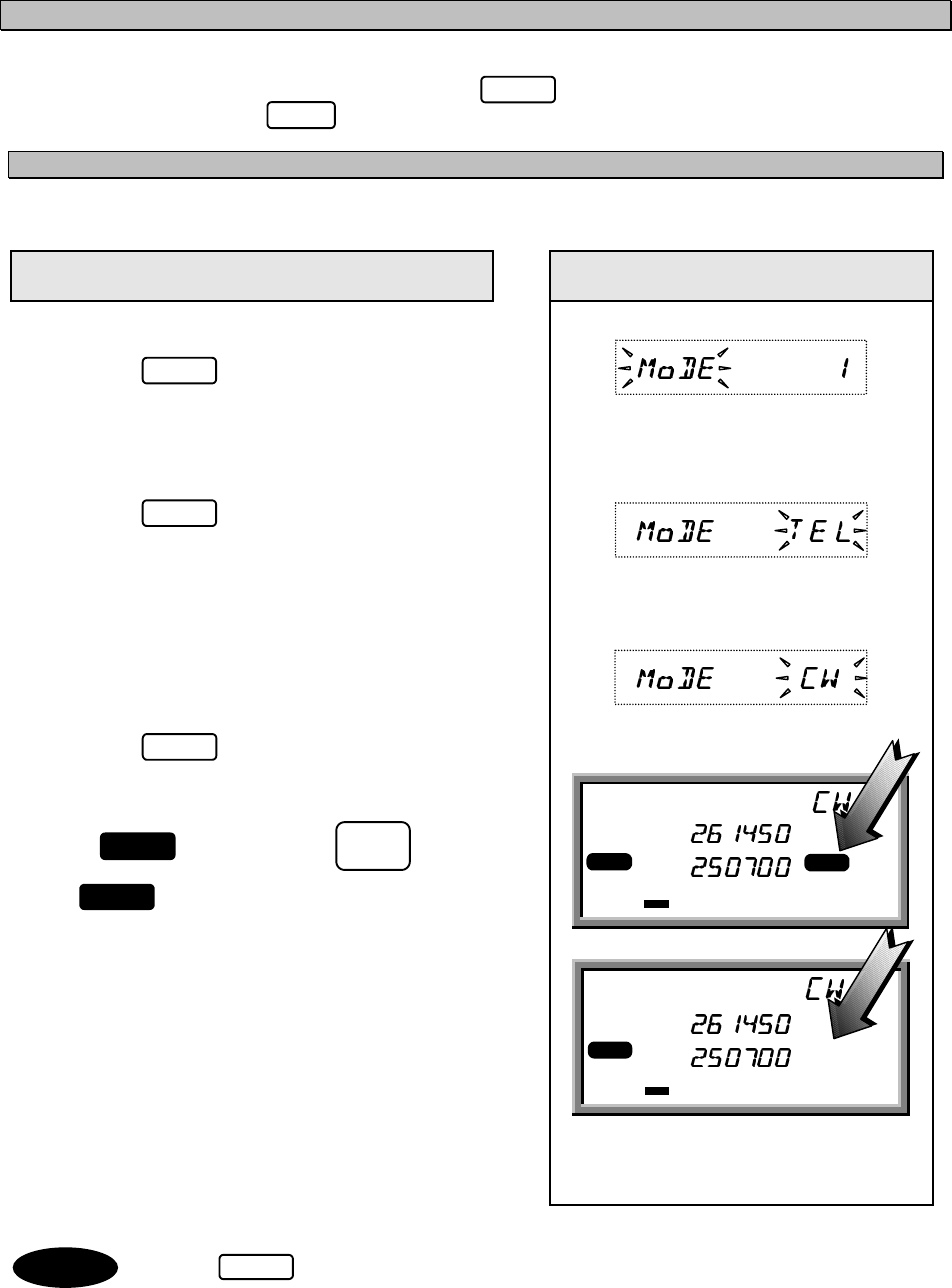
3.4.3.1 Setting the communication mode
In the use of manually inputting frequency, communication mode must be set in advance.
Procedure Examples of display on the LCD
Example of CW.
1. Press .
"MODE" in the channel field of the LCD
blinks.
(in the TEL mode)
2. Press .
The current communication mode "TEL"
blinks.
3. Turn the Jog Dial.
Turn the Jog Dial until objective mode.
"CW" is blinking.
4. Press .
CW is fixed as communication mode.
5. If is blinking, press .
lights steadily during tuning. And
disappear when tuning is complete.
• Press to change the communication mode successively.
MENU
ENT
MENU
ENT
ANT
TUNE
TUNE
TUNE
ENT
RX FREQ KHz
TX FREQ KHz
NB
AGC
TUNE
,
,,
, .
..
.
,
,,
, .
..
.
RDY
RX FREQ KHz
TX FREQ KHz
NR
A
GC
RDY TUNE
,
,,
, .
..
.
,
,,
, .
..
.
Note CLR

3-13
3.4.3.2 Setting the output power
The output power can be set to "HI (150W)" or "LOW (50W)".
Procedure Examples of display on the LCD
1. Press ,then turn the Jog Dial until
"Power" in the channel field of the LCD
blinks.
2. Press .
The current out power "HI" blinks.
3. Turn the Jog Dial until "LOW " blinks.
4. Press .
The output power is set to "LOW ".
on the lower right corner of the LCD
turns on.
3.4.3.3 Turning the Automatic Gain Control (AGC) ON
The AGC circuit functions to maintain a constant receiver output by automatically adjusting the gain
according to the strength of the reception signals.
Procedure Examples of display on the LCD
1. Press , then turn the Jog Dial until
"AGC" in the channel field blinks.
2. Press .
The current AGC status "SLW" blinks.
3. Turn the Jog Dial until desirable state "FST"
or "OFF" appears.
4. Press .
The desirable "AGC" state is fixed.
“AGC” turn on the right corner of the LCD
when you set to "SLW" or "FST".
In “TLX” mode, “AGC” state is fixed to “FST”. (You can not set to “SLW”.)
MENU
ENT
ENT
LO
MENU
ENT
ENT
Note
3-14
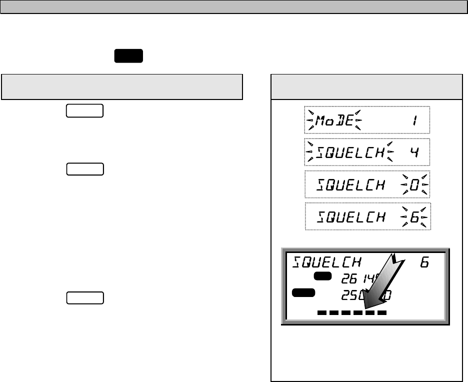
3.4.3.4 Adjusting squelch level
The squelch circuit functions to mute received signals based on its level. The larger the squelch level,
the larger the antenna input level is required to open the squelch circuit. When the squelch circuit is
activated (mute status), in the LCD turns on.
Procedure Examples of display on the LCD
1. Press ,then turn the Jog Dial until
"SQUELCH" blinks.
2. Press .
The current squelch level “0” blinks.
3. Turn the Jog Dial until desired squelch level
appears. When turn the Jog Dial, the bar on
the bottom of the LCD expands to indicate
the squelch level.
4. Press .
The squelch level is fixed.
MENU
ENT
RX FREQ
,
,,
,
.
..
.KHz
TX FREQ
,
,,
,
.
..
.KHz
SQL NR
AGC
RDY TUNE
SQL
ENT
3-15
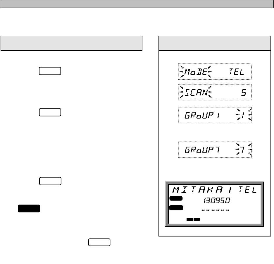
3.4.3.5 Setting the scanning speed
The scanning time for each channel is settable between 0.3 to 5 seconds.(multiple of 0.1 second)
Procedure Examples of display on the LCD
Example of 0.3 seconds.
1. Press , then turn the Jog Dial until
"SCAN SPD" blinks.
2. Press .
The current value “10” blinks.
3. Turn the Jog Dial until desirable scanning
time appears or manually input the value
from keypad.
4. Press .
The scanning time is fixed to 0.3 seconds.
3.4.3.6 Registering the user channel
You use frequently can be registered as a user channel up to 200, channel number 1 to 200.
Procedure Examples of display on the LCD
Example of registration for RX frequency 4357.0
kHz / TX frequency 4065.0 kHz, communication
mode is TEL, Channel Label Registration is
MITAKA1 at the user channel number 1.
1. Make sure that a objective communication
mode is set and press and then
turn the Jog Dial until "USR MEMO" blinks.
2. Press .
Select the user channel number with the Jog
Dial or keypad.
3. Press .
Select the communication mode with the Jog
Dial(*1).
MENU
ENT
ENT
MENU
ENT
ENT
3-16
Procedure Examples of display on the LCD
4. Press .
Press , , , and for
the RX frequency. The RX frequency is
displayed in the channel field of the LCD.
5. Press .
The RX frequency is fixed(*2).
6. Press , , , and for
the TX frequency. The TX frequency is
displayed in the channel field of the LCD.
7. Press .
The TX frequency is fixed.
8. Select an alphabet or number(MITAKA1)
with the Jog Dial. Input decision or “SPACE”
key is .
After selection, press ,
and fix to press (*3).
9. The Channel Label Registration mode is
set. If you want to complete the inputting
user channel, two times .
*1 When correct the registered channel, press , then select the collection item
as follows:
In case of change the communication mode or clear the channel, turn the Jog Dial.
Then press .
In case of change the RX or TX frequency or the channel Label,
press successively and input the new parameter.
*2 In step 2, the frequency can be inputted manually. RX frequency and a TX
frequency in this order and go to step 8 (When you want to use an identical
frequency for reception and transmission, press only after inputting RX
frequency).
*3 In step 7, you do not need the label, press and go to step 9.
Note
ENT
ENT
ENT
CLR
ENT
ENT
CLR
ENT
4 3 5 7 0
ENT
406 5 0
CH
RX FREQ KHz
TX FREQ KHz
NR
AGC
,
,,
, .
..
.
,
, ,
, .
. .
.
RDY
RX FREQ KHz
TX FREQ KHz
NB
AGC
TUNE
,
,,
, .
..
.
,
,,
, .
..
.
RDY
RX FREQ KHz
TX FREQ KHz
NB
AGC
TUNE
,
,,
, .
..
.
,
,,
, .
..
.
RDY
ENT
ENT
3-17
3.4.3.7 Registering a channel group name
200 user channels are grouped into 10 groups, each 20 channels. These groups are used for
scanning reception, and can be named for quick selection.
Procedure Examples of display on the LCD
1. Press , then turn the Jog Dial until
"GRP MEMO" blinks.
2. Press .
A group number “1” blinks in the right end of
the channel field of the LCD.
3. Turn the Jog Dial until the objective group
appears.
4. Press .
“_” blinks.
5. Repeat to select an alphabet or number
with the Jog Dial, and press eight
times.
6. Channel group number is fixed.
MENU
ENT
ENT
ENT
3-18
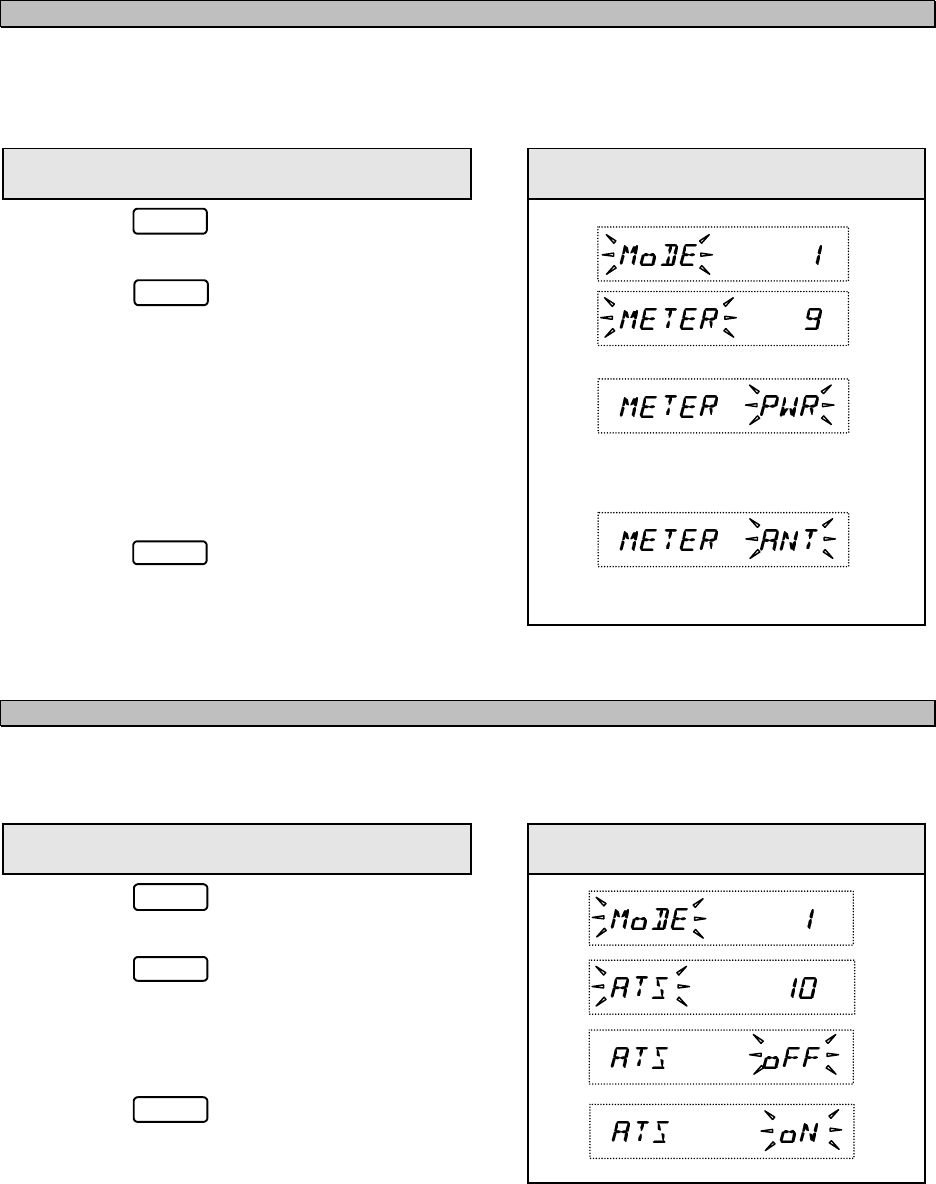
3.4.3.8 Setting the meter indication mode
The bar indicator on the bottom of the LCD indicates signal level during reception or output during
transmission, furthermore output indication is settable to the output power mode or antenna current
mode.
Procedure Examples of display on the LCD
1. Press , then turn the Jog Dial until
"METER" blinks .
2. Press .
"PWR" blinks.
3. Turn the Jog Dial until desired mode
appears.
"PWR" : Indication for output power.
"ANT" : Indication for antenna current.
4. Press .
Indication mode, "PWR" or "ANT", is fixed.
3.4.3.9 Setting the Automatic Tuning Start (ATS)
The ATS function is used for pre-tuning at change of channel / frequency, and tuning starts
automatically when the standing-wave ratio (SWR) is wrong.
Procedure Examples of display on the LCD
1. Press , then turn the Jog Dial until
"ATS" blinks.
2. Press .
"OFF" blinks.
3. Turn the Jog Dial to set "ON" or "OFF".
4. Press .
The ATS function is turned "ON" or "OFF" .
MENU
ENT
ENT
MENU
ENT
ENT
3-19
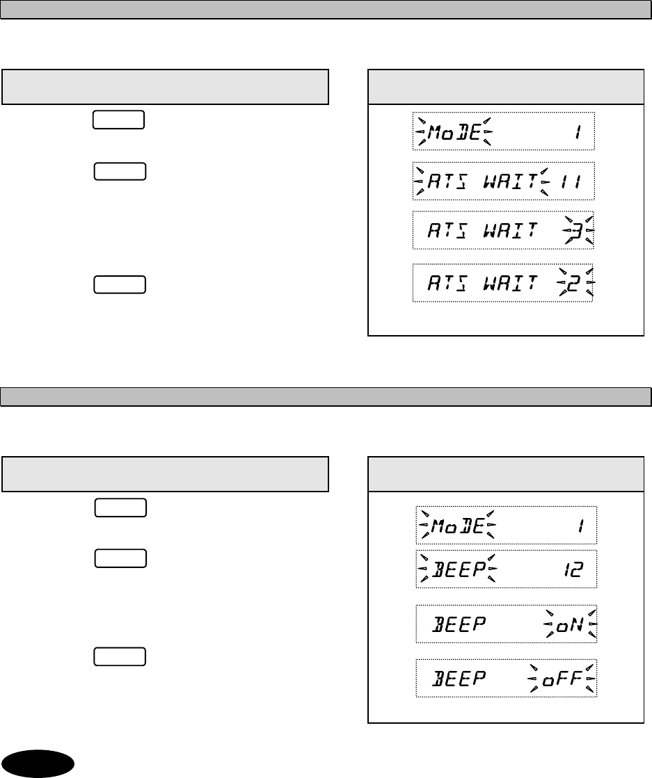
3.4.3.10 Setting the wait time for ATS
On the ATS function, wait time for tuning start after change of channel / frequency is adjustable.
Procedure Examples of display on the LCD
1. Press , then turn the Jog Dial until
"ATS WAIT" blinks.
2. Press .
"3" blinks.
3. Turn the Jog Dial to select the time or
manually input the time with keypad.
4. Press .
The wait time is fixed.
3.4.3.11 Turning the key-in sounds ON / OFF
The key-in sounds are available for keypad operation.
Procedure Examples of display on the LCD
1. Press , then turn the Jog Dial until
"BEEP" blinks.
2. Press .
“BEEP” lights steadily and "ON" blinks.
3. Turn the Jog Dial to select "ON" or "OFF".
4. Press .
The key-in sounds are turned "ON" or
"OFF".
The key-in sounds are suspended, when set the loudspeaker OFF.
MENU
ENT
ENT
ENT
ENT
MENU
Note
3-20
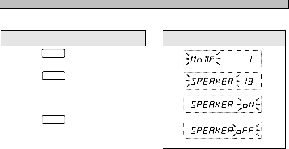
3.4.3.12 Setting the loudspeaker output ON / OFF
The loudspeaker output can be turned OFF.
Procedure Examples of display on the LCD
1. Press , then turn the Jog Dial until
"SPEAKER" blinks.
2. Press .
"SPEAKER" lights steadily and "ON" blinks.
3. Turn the Jog Dial to select "ON" or "OFF".
4. Press .
The loudspeaker output is turned "ON" or
"OFF".
MENU
ENT
ENT

3-21
3.4.3.13 List of shortcut keys
The following shortcut keys are provided for easy selection of menu items.
Using a shortcut key: The expression "1. Press , then turn the Jog Dial" in the above
procedure steps can be substituted by " Press and input its shortcut key number with
keypad".
Menu item Shortcut key
number Function
MODE 1 Select the communication mode.
TEL (J3E), DSC (F1B), TLX (F1B), CW (A1A), AME (H3E)
POWER 2 Set the output power to low (50 watts).
AGC 3 Select the AGC (Auto Gain Control) function.
SQUELCH 4 Adjust the squelch level.
SCAN 5 Enable the scanning function.
SCAN SPD 6 Set the scanning time.
USR MEMO 7 Register the user channel.
GRP MEMO 8 Register the channel group name.
METER 9 Select the bar-meter function.
ANT: antenna current, PWR: output power.
ATS 10 Enable the ATS (Automatic Tuning Start) function.
ATS WAIT 11 Set the wait time for the ATS function.
BEEP 12 Disable the key-in sound panel.
SPEAKER 13 Disable the output of the built-in loudspeaker.
CHECK 14 Perform the Self Diagnosis function.
VERSION 15 Display the farm-ware version on Control unit CDJ-1960, DSP,
Antenna Tuner and Power Amplifier.
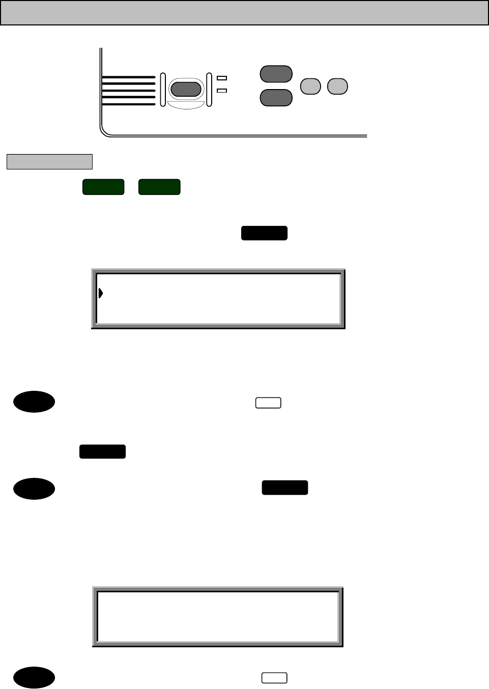
In JSS-296, Control unit’s version must be 2.00 or later.
MENU
MENU
Note
3-22
3-23
3.5 DSC operations
This section describes menus and modes (Section 3.5.1), receiving DSC calls (Section 3.5.2), and making DSC
calls (Section 3.5.3). Section 3.5.4 describes how to store the calling frequencies used with the DSC, and the
setting of destination IDs, etc.
3.5.1 Menus and Modes
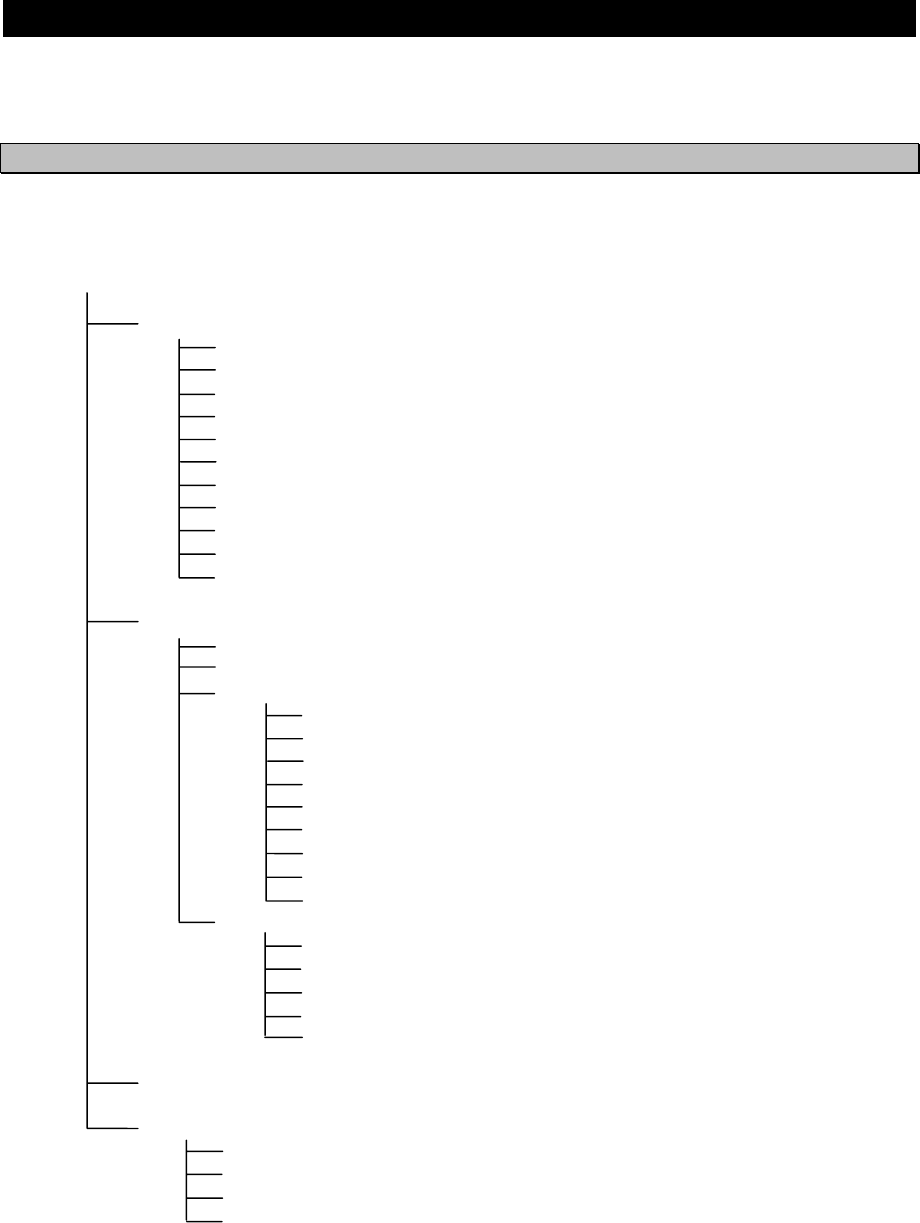
(1) Menu Hierarchy
The menus displayed on the screen have the following hierarchical structure.
DSC watching
MENU#1-EDIT&CALL
1.Individual call
2.Acknowledgement call
3.Distress call
4.Distress relay call
5.Auto/semi-auto call
6.All ships call
7.Group call
8.Area call
9.Position request
10.Polling call
11.Test call
MENU#2-READOUT&SETUP
1.Received distress message readout
2.Received others message readout
3.Setup
1.Data&time edit
2.Position edit
3.Calling frequency registration
4.Address registration
5.Distress setup
6.Others alarm setup
7.Automatic acknowledgement setup
8.Scanning setup
9.Watchkeeping receiver setup
4.Self test
1.Modem loop test
2.Printer test
3.Display test
4.Frequency remote test
5.Watchkeeping receiver test
RECEIVED MESSAGE
PRINT MENU
1.ALL RECEIVED DISTRESS MESSAGES
2.ALL RECEIVED OTHERS MESSAGES
3.ALL EDIT/CALL MESSAGES
4.ALL SETUP INFORMATION
3-24
(2) Transition Among Modes
The following chart shows the keys and key combinations used to shift from one mode to another
on the NCT-196N.
Select print menu.
Quit print menu.
Received message
Press once to clear the call alarm
and call lamp.
Press once more to quit call
message display mode.
No. selection
Discards the current edits and quits
editing.
Saves the current edits and quits
editing.
or Quits readout of received message.
No. selection
No. selection
No. selection
Discards the current settings and
quits editing.
Saves the current settings and
quits editing.
Stops self-diagnostic tests.
Quits self-diagnostic mode.
(From any mode, press three times to return to "DSC watching.")
DSC
watching Display and print
received message.
MENU #1
MENU #2
Print
menu
Message
editing
Self
dia
g
nosis
Various
settings
Readout
received
message.
4
FUNC
FUNC 3
STOP
STOP
4
FUNC
9
FUNC
MENU
MENU
MENU
4
FUNC
4
FUNC
STOP
4
FUNC
9FUNC
STOP
9
FUNC
FUNC
STOP
4
3-25
3.5.2 Receiving Messages
(1) Receiving a Message
When a message is received, it is displayed on the screen and printed out on the printer, if a printer is connected.
In addition, depending on its content, the message is classified as either a distress/urgent message or a general
message and the corresponding panel lamp blinks. Simultaneously, a buzzer sounds to indicate which type of
message has been received. The message is then saved as either a distress/urgent message or a general
message.
The NCT-196N stores up to 20 received distress/urgent messages and up to 20 general messages. When 20
messages have been stored, the oldest message is deleted each time a new message is received.
In case of distress/urgent messages, newly received messages are not stored if a message with the same content
already exists in memory. However, if any error occurs while receiving the message, both of the messages
containing the error and the error-free message are stored.
In case of general messages, the NCT-196N stores both the original message and the new message even if they
have the same content as each other.
Distress/urgent messages ・・・・・Messages in "DISTRESS" format or for which the category is
"DISTRESS" or "URGENCY".
General messages ・・・・・・・・・・・Messages other than distress/urgent messages.
Print received
message.
Is this a distress or
urgent message?
●DISTRESS/URGENCY lamp lights.
●Distress/urgent buzzer sounds.
●Message stored internally as distress/urgent
message.
●Note, however, that if a message with identical
content has already been received, this
message is not stored.
●OTHERS lamp lights.
●General call buzzer sounds.
●Message stored internally as general message.
●Note that even if a message with identical
content has already been received, this
message is stored.
YES
YESYES
YES
NO
NONO
NO
Note
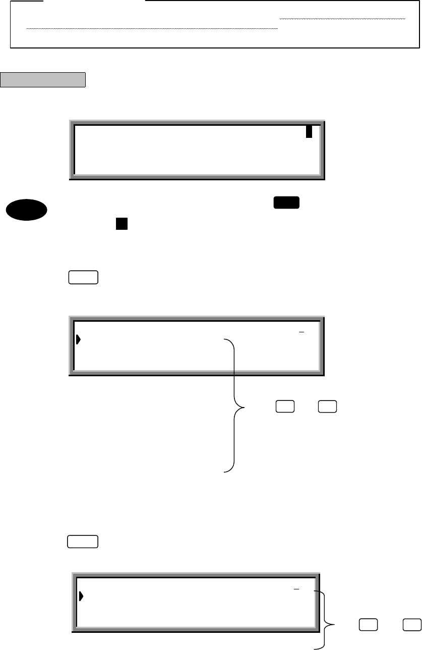
3-26
Use and to scroll.
(2) Reading a Distress/Urgent Message
Messages are loaded at the "DSC watching" screen.
ATTENTION
To prevent unnecessary distress message relay transmission, the NCT-196N automatically deletes
distress/urgency messages after 48 hours since these received. Thus the procedure above-
mentioned to read distress message received is invalid at that time.
Procedure
1. Check that the "DSC watching" screen is displayed.
If the "DSC watching" screen is not displayed, press 3 times in succession to switch to the
"DSC watching" screen.
On the screen mark is displayed when no printer is connected to the NCT-196N.
2. Press
.
The "MENU#1-EDIT&CALL" screen is displayed.
3. Press
again.
The "MENU#2-READOUT&SETUP" screen is displayed.
STOP
MENU
MENU
DSC watching 06.Sep.2001(Thu) 01:26 P
12゚34’N123゚45’E SPEED:12.4KT at 01:26
Self-ID = XXXXXXXXX [UTC]
MENU #1-EDIT&CALL Select no.
1.Individual call
2.Acknowledgement call
3.Distress call
4.Distress relay call
5.Auto/semi-auto call
6.All ships call Use and to scroll.
7.Group call
8.Area call
9.Position request
10.Polling call
11.Test call
▼
▲
MENU #2 -READOUT&SETUP Select no.
1.Received distress message readout
2.Received others message readout
3.Setup
4.Self test
▲
▼
P
Note
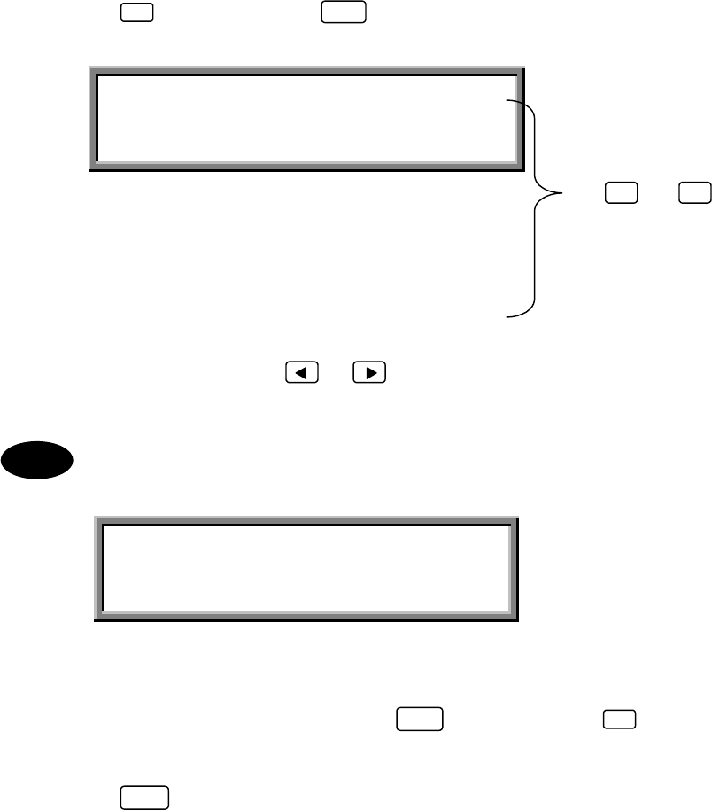
3-27
RECEIVED DISTRESS MESSAGE READOUT #01
RX date&time :06.Sep.2001(Thu) 01:26
Format :DISTRESS
Address :XXXXXXXXX
Nature :UNDESIGNATED DIST
Dist-position :12 ゚34’N123 ゚45’E
Dist-UTC :01:26
Dist-telecomm :J3E TEL
End of sequence:EOS
RX frequency : . kHz
Use and to scroll.
4. Press
, and then press
.
The "RECEIVED DISTRESS MESSAGE READOUT" screen is displayed.
Use the horizontal cursor keys ( and ) to display other received messages.
The following screen is displayed if no distress messages have been received or deleted after
48hours past.
5. After reading the message(s), press
, and then press
.
Operation returns to the "MENU#2 READOUT&SETUP" screen.
6. Press
.
Operation returns to the "DSC watching" screen.
1ENT
▲
▼
RECEIVED DISTRESS MESSAGE READOUT
Received message not found !!
MENU
FUNC 4
Note
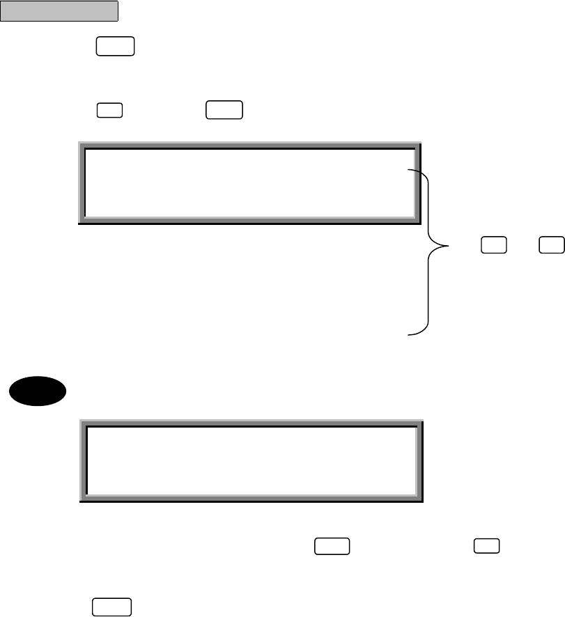
3-28
Use and to scroll.
(3) Reading a General Message
Messages are loaded at the "DSC watching" screen.
Procedure
1. Press
twice to display the "MENU#2-READOUT&SETUP" screen.
The screen shown in step 3 of "(2) Reading a Distress/Urgent Message" is displayed.
2. Press
, and then
.
The following screen is displayed if no general messages have been received.
3. After reading the message(s), press
, and then press
.
Operation returns to the "MENU#2 READOUT&SETUP" screen.
4. Press
.
Operation returns to the "DSC watching" screen.
MENU
2ENT
RECEIVED OTHERS MESSAGE READOUT #01
RX date&time :06.Sep.2001(Thu) 01:26
Format :INDIVIDUAL
Address :XXXXXXXXX
Category :ROUTINE
Telecommand1 :J3E TEL
Telecommand2 :NO INFORMATION
Work TX/RX freq:12,321.0/12,343.2 kHz
End of sequence:ACK RQ
RX frequency :12,187.5 kHz
RECEIVED OTHERS MESSAGE READOUT
Received message not found !!
MENU
FUNC 4
▲
▼
Note

3-29
3.5.3 Sending Messages
The following table lists the menus and menu items. When compiling a message, select the necessary items from
these menus. Refer to the section on making calls for how to select the items for the respective call types.
Menu Menu items Content
FORMAT INDIVIDUAL
AUTO/SEMI−AUTO
DISTRESS
ALL SHIPS
GROUP
AREA
CATEGORY URGENCY
SAFETY
SHIP’S BUSINESS
ROUTINE
DISTRESS
TELECOMMAND1 POLLING
UNCOMPLY
DATA MODEM
J3E TEL
F1B/J2B FEC TTY
F1B/J2B ARQ TTY
F1B/J2B REC TTY
F1B/J2B TTY
A1A MORSE RECORD
SHIP’S POSITION
A1A MORSE KEY
F1C/F2C/F3C FAX
NO INFORMATION
F3E/G3E SIMP TEL
F3E/G3E DUP TEL
DISTRESS RELAY
DISTRESS ACK
END OF SEQUENCE
TEST
TELECOMMAND2 NO INFORMATION
RES18SHIP/AIR
MEDICAL TRANS
PUB CALL OFFICE
NO REASON
CONGESTION
BUSY
QUEUE
STATION BARRED
NO OPERATOR
NO OPR TEMPRY
EQUIP DISABLED
UNUSABLE FREQ
UNUSABLE MODE
ITU−T V.21
ITU−T V.22
ITU−T V.22 BIS
ITU−T V.23
ITU−T V.26 BIS
ITU−T V.26 TER
ITU−T V.27 TER
ITU−T V.32

3-30
Menu Menu items Content
NATURE UNDESIGNATED DIST
ABANDONING
EPIRB EMISSION
FIRE/EXPLOSION
FLOODING
COLLISION
GROUNDING
LISTING
SINKING
DISABLED/ADRIFT
MAN OVERBOARD
PIRACY/ROBBERY
TELECOMMAND J3E TEL
F3E/J3E SIMP TEL
F3E/J3E DUP TEL
F1B/J2B FEC TTY
F1B/J2B ARQ TTY
EOS ACK RQ
ACK BQ
EOS
3-31
(1) INDIVIDUAL CALL
Compiling and transmitting the message is enabled by specifying the address of a specific coastal or ship station.
FORMAT
FORMATFORMAT
FORMAT
INDIVIDUAL
ADDRESS
ADDRESSADDRESS
ADDRESS
XXXXXXXXX
CATEGORY
CATEGORYCATEGORY
CATEGORY
URGENCY
SAFETY
SHIP'S BUSINESS
ROUTINE
DISTRESS
SHIP'S POTISION
SHIP'S POTISIONSHIP'S POTISION
SHIP'S POTISION
12°34'N123°45'E
WORK TX/RX FREQ
WORK TX/RX FREQWORK TX/RX FREQ
WORK TX/RX FREQ
12345.6/12346.5
CALL TX/RX FREQ
CALL TX/RX FREQCALL TX/RX FREQ
CALL TX/RX FREQ
4208.0/4219.5
EOS
EOSEOS
EOS
ACK RQ
DIST-ADDRESS
DIST-ADDRESSDIST-ADDRESS
DIST-ADDRESS
XXXXXXXXX
NATURE
NATURENATURE
NATURE
UNDESIGNATED DIST
ABANDONING
EPIRB EMISSION
FIRE/EXPLOSION
FLOODING
COLLISION
GROUNDING
LISTING
SINKING
DISABLED/ADRIFT
DIST-UTC
DIST-UTCDIST-UTC
DIST-UTC
12:34
DIST-TELECOMM
DIST-TELECOMMDIST-TELECOMM
DIST-TELECOMM
J3E TEL
F1B/J2B FEC TTY
F1B/J2B ARQ TTY
F3E/G3E SIMP TEL
F3E/G3E DUP TEL
TELECOMMAND-1
TELECOMMAND-1TELECOMMAND-1
TELECOMMAND-1
J3E TEL
F1B/J2B FEC TTY
F1B/J2B ARQ TTY
F1B/J2B REC TTY
F1B/J2B TTY
A1A MORSE RECORD
SHIP'S POSITION
A1A MORSE KEY
F1C/F2C/F3C FAX
NO INFORMATION
F3E/G3E SIMP TEL
F3E/G3E DUP TEL
POLLING
UNCOMPLY
TELECOMMAND-1
TELECOMMAND-1TELECOMMAND-1
TELECOMMAND-1
DATA MODEM
TELECOMMAND-1
TELECOMMAND-1TELECOMMAND-1
TELECOMMAND-1
TELECOMMAND-1
TELECOMMAND-1TELECOMMAND-1
TELECOMMAND-1
TEST
TELECOMMAND-1
TELECOMMAND-1TELECOMMAND-1
TELECOMMAND-1
DISTRESS RELAY
DIST-POTISION
DIST-POTISIONDIST-POTISION
DIST-POTISION
12°34'N123°45'E
PIRACY/ROBBERY
MAN OVERBOARD
TELECOMMAND-2
TELECOMMAND-2TELECOMMAND-2
TELECOMMAND-2
NO INFORMATION
RES18 SHIP/AIR
MEDICALTRANS
TELECOMMAND-2
TELECOMMAND-2TELECOMMAND-2
TELECOMMAND-2
NO INFORMATION
ITU-T V.21
ITU-T V.22
ITU-T V.22 BIS
ITU-T V.23
ITU-T V.26 BIS
ITU-T V.26 TER
ITU-T V.27 TER
ITU-T V.32
PUB CALL OFFICE
RES18 SHIP/AIR
MEDICALTRANS
NO INFORMATION
TELECOMMAND-2
TELECOMMAND-2TELECOMMAND-2
TELECOMMAND-2
TELECOMMAND-2
TELECOMMAND-2TELECOMMAND-2
TELECOMMAND-2
NO REASON
CONGESTION
BUSY
QUEUE
STATION BARRED
NO OPERATOR
NO-OPR TEMPRLY
EQUIP DISABLED
UNUSABLE FREQ
UNUSABLE MODE
NOTE:can only be selected when SAFETY category is selected.
NOTE:can only be selected when
DISTRESS category is selected and the destination is a coastal station.
3-32
INDIVIDUAL CALL Transmissible
Address :XXXXXXXXX
Category :ROUTINE
Telecommand-1 :J3E TEL
Telecommand-2 :NO INFORMATION
Ship’s position:12 ゚34’N123 ゚45’E
Call TX/RX freq: 4,208.0/ 4,219.5 kHz
Use and to
scroll the screen.
Procedure
Example: ROUTINE procedure.
1. Check that the "DSC watching" screen is displayed.
2. Press
.
The "MENU#1-EDIT&CALL" screen is displayed.
3. Press
, and then press
.
The "INDIVIDUAL CALL" screen is displayed.
The following items have been set in this example.
「Address」:
XXXXXXXXX
「Category」:ROUTINE
「Telecommand-1」:J3E TEL
「Telecommand-2」:NO INFORMATION
「Ship’s position」:12 ゚34’N123 ゚45’E
「Call TX/RX freq」:4,208.0/4,219.5 kHz
MENU
1ENT
▲
▼
DSC watching 06.Sep.2001(Thu) 01:26
12゚34’N123゚45’E SPEED:12.4KT at 01:26
Self-ID = XXXXXXXXX [UTC]
MENU #1-EDIT&CALL Select no.
1.Individual call
2.Acknowledgement
3.Distress call
4.Distress relay call
5.Auto/semi-auto call
6.All ships call Use and to scroll the screen.
7.Group call
8.Area call
9.Position request
10.Polling call
11.Test call
▼
▲
3-33
●Entering the respective items:
After selecting each item, press to confirm the selection.
(1) Address: Use the numerical keys ( to ) to specify the address of the destination
station (coastal or ship station).
(2) Category
Telecommand-1: Use the and keys to select the items.
Telecommand-2
(3) Ship's position: Use the and keys to determine the direction, and then input the
ship's position using the numerical keys ( to ).
(4) Call TX/RX freq: Use the and keys to select one of the preset frequencies, or use
the numerical keys ( to ,and ) to specify a frequency directly.
(5) Other settings:
・"Work TX/RX freq": Use the numerical keys ( to ,and ) to specify a frequency
directly.
・Switching from "Ship's position" to "Work TX/RX freq": Press (FREQ).
・Switching from "Work TX/RX freq" to "Ship's position": Press (POS).
Set the "Work TX/RX freq" to a frequency in the same band as "Call TX/RX freq".
4. Press
.
The following screen is displayed and the message is transmitted.
When the transmission is completed, the following screen is displayed for a while, and the message is
saved. After that returns to the "MENU#1-EDIT&CALL" screen.
Refer to the example in "(6) ALL SHIPS CALL" for information on the DISTRESS RELAY procedure.
To store a message without sending it, press (SAVE).
To discard the message and quit, press (QUIT).
0 9
09
0 9 .
FUNC 6
FUNC 5
ENT
CALL
INDIVIDUAL CALL Transmitting
TX frequency : 4,208.0 kHz
TX date&time : 06.Sep.2001(Thu) 01:30
INDIVIDUAL CALL Send Completed
TX frequency : 4,208.0 kHz
TX date&time : 06.Sep.2001(Thu) 01:30
FUNC
9FUNC
4
0 9 .
Note
Note
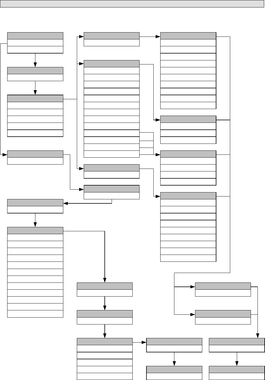
3-34
(2) ACKNOWLEDGEMENT CALL
In the event that the received general message requests acknowledgement, a message of acknowledgement is
automatically produced. Creating and transmitting a distress acknowledgement message is also possible.
FORMAT
FORMATFORMAT
FORMAT
INDIVIDUAL
ADDRESS
ADDRESSADDRESS
ADDRESS
XXXXXXXXX
CATEGORY
CATEGORYCATEGORY
CATEGORY
URGENCY
SAFETY
SHIP'S BUSINESS
ROUTINE
DISTRESS
TELECOMMAND-1
TELECOMMAND-1TELECOMMAND-1
TELECOMMAND-1
J3E TEL
F1B/J2B FEC TTY
F1B/J2B ARQ TTY
F1B/J2B REC TTY
F1B/J2B TTY
A1A MORSE RECORD
SHIP'S POSITION
A1A MORSE KEY
F1C/F2C/F3C FAX
NO INFORMATION
F3E/G3E SIMP TEL
F3E/G3E DUP TEL
POLLING
UNCOMPLY
TELECOMMAND-2
TELECOMMAND-2TELECOMMAND-2
TELECOMMAND-2
NO INFORMATION
RES18 SHIP/AIR
MEDICALTRANS
PUB CALL OFFICE
TELECOMMAND-2
TELECOMMAND-2TELECOMMAND-2
TELECOMMAND-2
NO INFORMATION
ITU-T V.21
ITU-T V.22
ITU-T V.22 BIS
ITU-T V.23
ITU-T V.26 BIS
ITU-T V.26 TER
ITU-T V.27 TER
ITU-T V.32
TELECOMMAND-2
TELECOMMAND-2TELECOMMAND-2
TELECOMMAND-2
NO REASON
CONGESTION
BUSY
QUEUE
STATION BARRED
NO OPERATOR
NO-OPR TEMPRLY
EQUIP DISABLED
UNUSABLE FREQ
UNUSABLE MODE
SHIP'S POTISION
SHIP'S POTISIONSHIP'S POTISION
SHIP'S POTISION
12°34'N123°45'E
WORK TX/RX FREQ
WORK TX/RX FREQWORK TX/RX FREQ
WORK TX/RX FREQ
12345.6/12346.5
CALL TX/RX FREQ
CALL TX/RX FREQCALL TX/RX FREQ
CALL TX/RX FREQ
2187.5/2187.5
EOS
EOSEOS
EOS
EOS
DIST-ADDRESS
DIST-ADDRESSDIST-ADDRESS
DIST-ADDRESS
NATURE
NATURENATURE
NATURE
DIST-POTISION
DIST-POTISIONDIST-POTISION
DIST-POTISION
12°34'N123°45'E
DIST-UTC
DIST-UTCDIST-UTC
DIST-UTC
12:34
DIST-TELECOMM
DIST-TELECOMMDIST-TELECOMM
DIST-TELECOMM
J3E TEL
F1B/J2B FEC TTY
F1B/J2B ARQ TTY
F3E/G3E SIMP TEL
F3E/G3E DUP TEL
TELECOMMAND-1
TELECOMMAND-1TELECOMMAND-1
TELECOMMAND-1
DATA MODEM
TELECOMMAND-1
TELECOMMAND-1TELECOMMAND-1
TELECOMMAND-1
XXXXXXXXX
ALL SHIPS
DISTRESS
CATEGORY
CATEGORYCATEGORY
CATEGORY
DISTRESS ACK
TELECOMMAND-2
TELECOMMAND-2TELECOMMAND-2
TELECOMMAND-2
NO INFORMATION
RES18 SHIP/AIR
MEDICALTRANS
CALL TX/RX FREQ
CALL TX/RX FREQCALL TX/RX FREQ
CALL TX/RX FREQ
4208.0/4219.5
EOS
EOSEOS
EOS
ACK BQ
TELECOMMAND-1
TELECOMMAND-1TELECOMMAND-1
TELECOMMAND-1
UNDESIGNATED DIST
ABANDONING
EPIRB EMISSION
FIRE/EXPLOSION
FLOODING
COLLISION
GROUNDING
LISTING
SINKING
DISABLED/ADRIFT
PIRACY/ROBBERY
MAN OVERBOARD
[Fixed]
[Fixed]
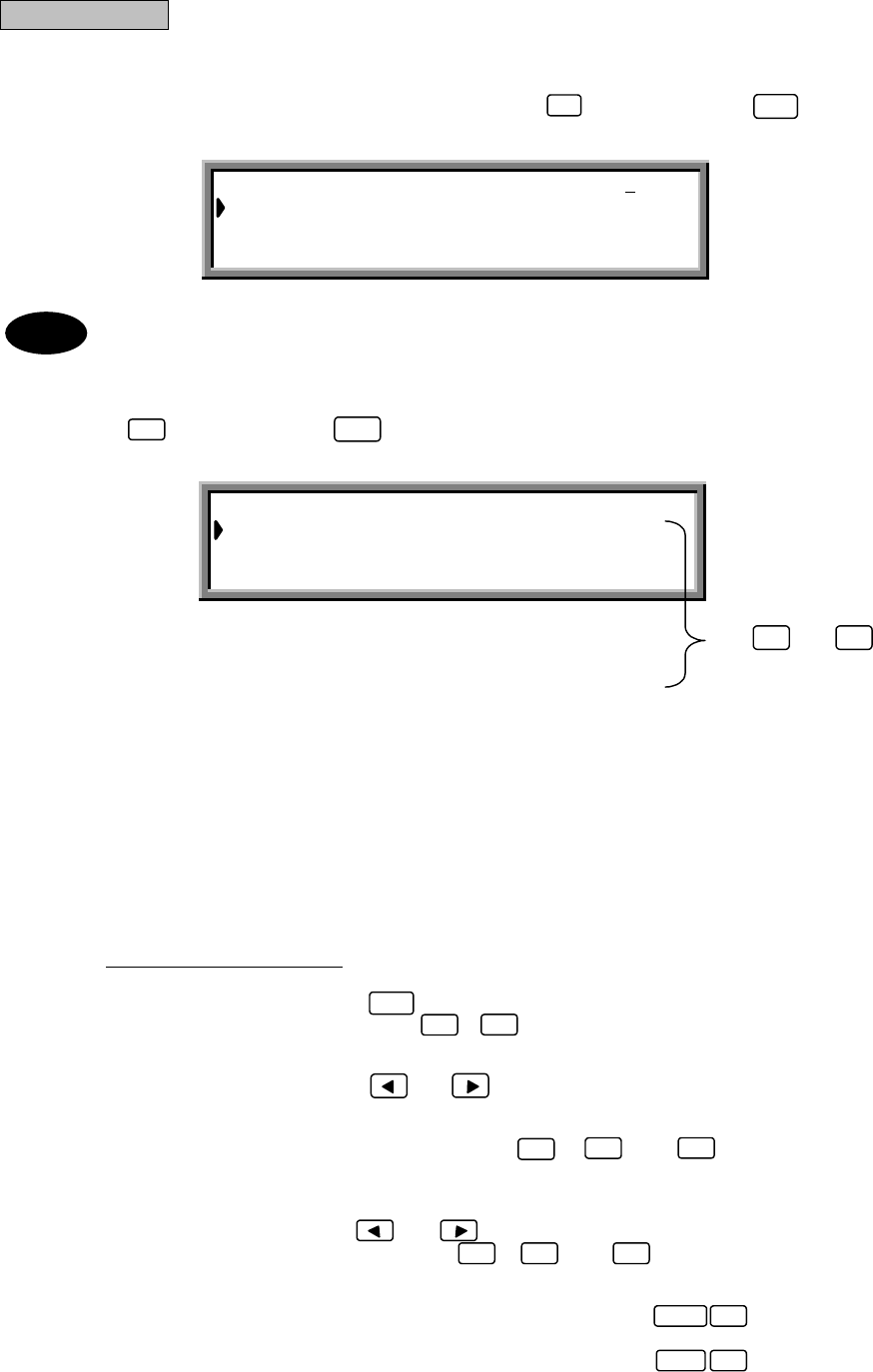
3-35
Use and to
scroll the screen.
(2-1)
INDIVIDUAL ACK CALL
Procedure
Example: An acknowledgement call based on the message received
1. From the "MENU#1-EDIT&CALL" screen, press
, and then press
.
The "Acknowledgement" screen is displayed.
1 :Select 1 to edit the received message.
2, 3 :Select 2 or 3 to edit a new acknowledgement message.
2. Press , and then press .
The "INDIVIDUAL ACK CALL" screen is displayed.
The following items have been set in this example.
「Address」:XXXXXXXXX
「Category」:
ROUTINE
「Telecommand-1」:
J3E TEL
「Telecommand-2」:NO INFORMATION
「Work TX/RX freq」:12,345.6/12,456.7 kHz
「Call TX/RX freq」:4,357.0/4,388.5 kHz
●Entering the respective items:
After selecting each item, press to confirm the selection.
(1) Address: Use the numerical keys ( to ) to specify the address of the destination station
(coastal or ship station).
(2) Category
Telecommand-1: Use the and keys to select the items.
Telecommand-2
(3) Work TX/RX freq: Use the numerical keys ( to , and ) to directly specify a
frequency.
(4) Call TX/RX freq: Use the and keys to select one of the preset frequencies, or use
the numerical keys ( to ,and ) to specify a frequency directly.
(5) Other settings:
・Switching from "Ship's position" to "Work TX/RX freq": Press (FREQ).
・Switching from "Work TX/RX freq" to "Ship's position": Press (POS).
2ENT
ACKNOWLEDGEMENT Select no.
1.INDIVIDUAL ack. Rcv:06.Sep.01:20
2.INDIVIDUAL ack. EDIT
3.DISTRESS ack. EDIT
1ENT
INDIVIDUAL ACK CALL
Address :XXXXXXXXX
Category :ROUTINE
Telecommand-1 :J3E TEL
Telecommand-2 :NO INFORMATION
Work TX/RX freq:12,345.6/12,456.7kHz
Call TX/RX freq: 4,357.0/ 4,388.5kHz
09
FUNC 6
FUNC 5
ENT
09.
▲
▼
Note
0 9 .

3-36
3. Press
.
The following screen is displayed and the message is transmitted.
If the tuner is not tuned to the transmission frequency, the "tuner mismatch!!" warning message is
displayed. Press to tune the tuner, then transmit the message.
When the transmission is completed, the following screen is displayed for a while. After that returns to the
"MENU#1-EDIT&CALL" screen.
・ Unable to store the message.
・ To discard the message and quit without sending it, press (QUIT).
CALL
INDIVIDUAL ACK CALL Transmitting
TX frequency : 4,357.0 kHz
TX date&time :06.Sep.2001(Thu) 01:30
INDIVIDUAL ACK CALL Send Completed
TX frequency : 4,357.0 kHz
TX date&time :06.Sep.2001(Thu) 01:30
FUNC 4
ENT
Note
Note
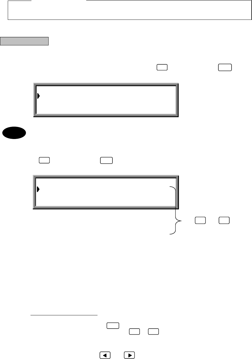
3-37
Use and to
scroll the screen.
(2-2)
DISTRESS ACK CALL
Perform the distress acknowledgement call as follows. The message is not made automatically because
confirmation of the distress condition is necessary. Compile the acknowledgment message manually and
then transmit it.
Compile the acknowledgment call so that the contents are the same as the received distress message.
ATTENTION
When a distress call is received, perform communication according to
"RECEPTION OF DSC DISTRESS ALERT".
Procedure
Example: Acknowledgement call procedure based on received distress message
1. From the "MENU#1-EDIT&CALL" screen, press
, and then press
.
The "Acknowledgement" screen is displayed.
1 :Select 1 to edit the received message.
2, 3 :Select 2 or 3 to edit a new acknowledgement message.
2. Press
, and then press
.
The "DISTRESS ACK CALL" screen is displayed.
The following items have been set in this example.
「Address」:XXXXXXXXX
「Nature」:UNDESIGNATED DIST
「Dist-position」:12 ゚34’N123 ゚45’E
「Dist-UTC」:01:20
「Dist-telecomm」:J3E TEL
「Call TX/RX freq」:2,187.5/2,187.5 kHz
●Entering the respective items:
After selecting each item, press to confirm the selection.
(1) Address: Use the numerical keys ( to ) to specify the address of the destination
station (coastal or ship station).
(2) Nature
Dist-telecomm: Use the and keys to select the items.
2ENT
DISTRESS ACK CALL
Dist-address :XXXXXXXXX
Nature :UNDESIGNATED DIST
Dist-position :12゚34’N123゚45’E
Dist-UTC :01:20
Dist-telecomm :J3E TEL
Call TX/RX freq: 2,187.5 / 2,187.5 kHz
0 9
ENT
ACKNOWLEDGEMENT Select no._
1.INDIVIDUAL ack. Rcv:06.Sep.01:20
2.INDIVIDUAL ack. EDIT
3.DISTRESS ack. EDIT
3ENT
▲
▼
Note

3-38
(3) Dist-position: Use the and keys to determine the direction, and then input the ship's
position using the numerical keys ( to ).
(4) Dist-UTC: Use the numerical keys ( to ) to enter the time.
(5) Call TX/RX freq: Use the and keys to select one of the preset frequencies, or use
the numerical keys ( to ,and ) to specify a frequency directly.
3. Press
.
The following screen is displayed and the message is transmitted.
If the tuner is not tuned to the transmission frequency, the following screen is displayed. Press to
tune the tuner and then transmit the message.
When the transmission is completed, the following screen is displayed and, after a brief interval, operation
returns to the "MENU#1-EDIT&CALL" screen.
・
Unable store the message.
・
To discard the message and quit without sending it, press (QUIT).
09
0 9
CALL
DISTRESS ACK CALL Transmitting
TX frequency : 2,187.5 kHz
TX date&time :06.Sep.2001(Thu) 01:30
DISTRESS ACK CALL Send Completed
TX frequency : 2,187.5 kHz
TX date&time :06.Sep.2001(Thu) 01:30
FUNC 4
tuner mismatch ! !
Press [ENT] key to tune & send
Press [CLR] key to send
ENT
Note
0 9 .
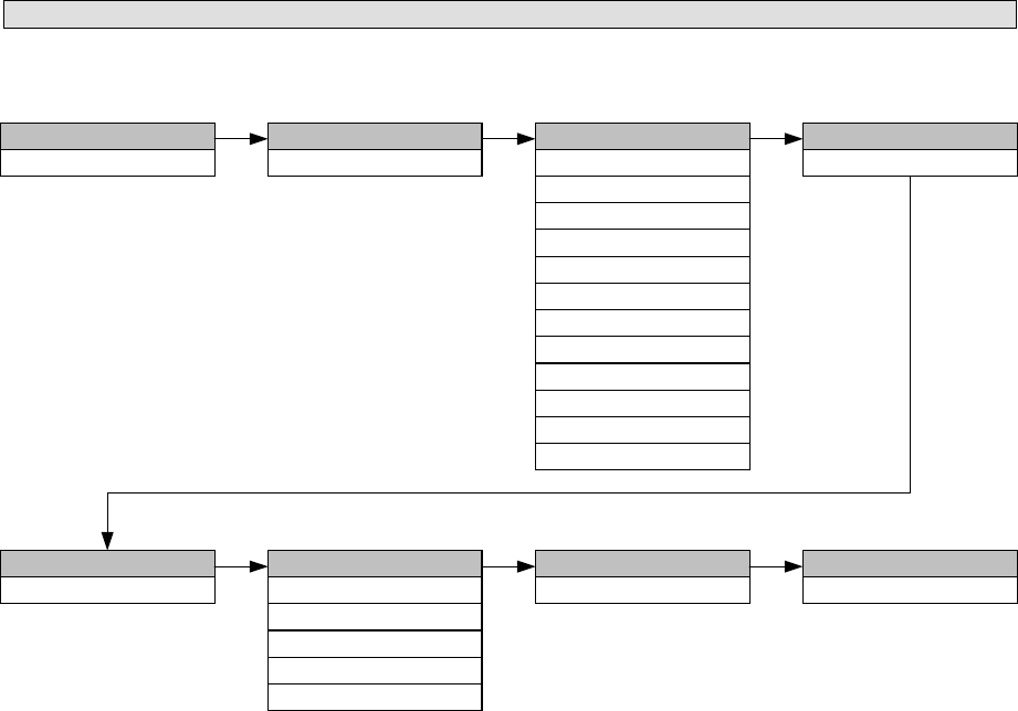
3-39
(3) DISTRESS CALL
Data such as the nature of the distress, position, and time can be compiled and transmitted in detail. A distress call
is transmitted repeatedly at 3.5- to 4.5-minute intervals until acknowledgement is received.
CALL TX/RX FREQ
CALL TX/RX FREQCALL TX/RX FREQ
CALL TX/RX FREQ
2187.5/2187.5
EOS
EOSEOS
EOS
EOS
DIST-ADDRESS
DIST-ADDRESSDIST-ADDRESS
DIST-ADDRESS NATURE
NATURENATURE
NATURE DIST-POTISION
DIST-POTISIONDIST-POTISION
DIST-POTISION
12°34'N123°45'E
DIST-UTC
DIST-UTCDIST-UTC
DIST-UTC
12:34
DIST-TELECOMM
DIST-TELECOMMDIST-TELECOMM
DIST-TELECOMM
J3E TEL
F1B/J2B FEC TTY
F1B/J2B ARQ TTY
F3E/G3E SIMP TEL
F3E/G3E DUP TEL
XXXXXXXXX
FORMAT
FORMATFORMAT
FORMAT
DISTRESS
UNDESIGNATED DIST
ABANDONING
EPIRB EMISSION
FIRE/EXPLOSION
FLOODING
COLLISION
GROUNDING
LISTING
SINKING
DISABLED/ADRIFT
PIRACY/ROBBERY
MAN OVERBOARD
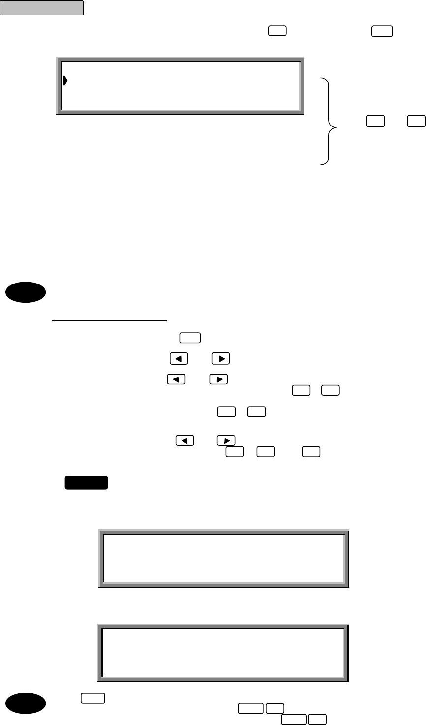
3-40
DISTRESS CALL Transmissible
Address :XXXXXXXXX
Nature :UNDESIGNATED DIST
Dist-position :12゚34’N123゚45’E
Dist-UTC :01:20
Dist-telecomm :J3E TEL
End of sequence :EOS
Call TX/RX freq :2,187.5 / 2,187.5 kHz
Use and to
scroll the screen.
Procedure
1. From the "MENU#1-EDIT&CALL" screen, press
, and then press
.
The "DISTRESS CALL" screen is displayed.
The following items have been set in this example.
*「Address」:
XXXXXXXXX
「Nature」:
UNDESIGNATED DIST
「Dist-position」:
12 ゚34’N123 ゚45’E
「Dist-UTC」:01:20
「Dist-telecomm」:J3E TEL
*「End of sequence」:EOS
「Call TX/RX freq」:2,187.5/2,187.5 kHz
* Not edit the these setting.
●Entering the respective items:
After selecting each item, press to confirm the selection.
(1) Nature
Dist-telecomm: Use the and keys to select the items.
(2) Dist-position: Use the and keys to determine the direction, and then input the
ship's position using the numerical keys ( to ).
(3) Dist-UTC: Use the numerical keys ( to ) to enter the time.
(4) Call TX/RX freq: Use the and keys to select one of the preset frequencies, or use
the numerical keys ( to ,and ) to specify a frequency directly.
2. Press
for at least 3.5 seconds (until the intermittent alarm tone changes to
a continuous tone).
The following screen is displayed and the message is transmitted. The same distress message is sent 5
times in succession.
On completion of the transmission, the following screen is displayed. Transmission of the distress call is
repeated when the displayed time has counted down to zero.
Press to cancel the DISTRESS transmission.
To store the message without sending it, press (SAVE).
To discard the message and quit without sending it, press (QUIT).
The distress call is sent repeatedly until a distress call acknowledgement is received.
3ENT
ENT
0 9
0 9
DISTRESS CALL Transmitting
TX frequency : 2,187.5 kHz
TX date&time :06.Sep.2001(Thu) 01:30
1/5
DISTRESS CALL 2,187.5 kHz
NEXT DISTRESS CALL:AFTER 3.7 min
DISTRESS
FUNC 9
FUNC 4
STOP
▲
▼
Note
Note
0 9 .
3-41
●About Distress Calls
Distress calls, distress relay and distress acknowledgement functions are described here.
○Distress Call Transmission
Distress type FORMAT CATEGOLY TELECOMMAND-1 Operating keys No. of transmissions
DISTRESS DISTRESS −− DISTRESS 5 successive transmissions
with intervals
DISTRESS DISTRESS −− CALL>DISTRESS 5 successive transmissions
with intervals
DISTRESS INDIVIDUAL
ALL SHIPS
GROUP
AREA
DISTRESS J3E TEL, etc. CALL>DISTRESS Once only
DISTRESS RELAY INDIVIDUAL DISTRESS DISTRESS RELAY CALL>DISTRESS Once only
DISTRESS RELAY ALL SHIPS DISTRESS DISTRESS RELAY CALL>DISTRESS Once only
DISTRESS ACK ALL SHIPS DISTRESS DISTRESS ACK CALL Once only
○Distress Calls
①When transmitting without editing and using only the key, the message with the contents
previously compiled in the distress setting is transmitted. This message is transmitted five times
successively at 3.5- to 4.5-minute intervals.
②The following are two ways of distress transmitting after editing:
1. Transmitting details of distress conditions
This transmission is made according to 3.5.3 (3), "DISTRESS CALL." The nature of the distress, the
ship's position, time, and communication method are transmitted. The message is transmitted five times
successively at 3.5- to 4.5-minute intervals.
This is the primary method.
2. This transmission includes INDIVIDUAL, ALL SHIPS, GROUP, and AREA, and it is enabled when
"DISTRESS" is selected for the CATEGORY. The contents of the message are the same as other
messages. This message is transmitted only once.
○DISTRESS RELAY CALL
This transmission is made according to 3.5.3 (4), "DISTRESS RELAY CALL." The message to be
transmitted can be edited by selecting "DISTRESS" for FORMAT and "DISTRESS RELAY" for CATEGORY
in individual or all ships calls. However, the contents are the same. The received message is edited so that it
is the same as the received distress message. It is then transmitted to a coastal station. This message is
transmitted only once.
○DISTRESS ACK CALL
This transmission is made according to 3.5.3 (2), "ACKNOWLEDGEMENT CALL (2-2)." The message is not
created automatically because the contents need to be confirmed. The acknowledgement message is
edited manually and then transmitted. It is necessary to edit the message to be transmitted according to the
contents of the received message. This message is transmitted only once by using key.
ATTENTION
When a distress message is received, make the transmission according to
"RECEPTION OF DSC DISTRESS ALERT".
DISTRESS
CALL