Japan Radio NCR-330 Marine User Manual
Japan Radio Co Ltd. Marine
UserManual.wiki
>
Japan Radio
>
NCR 330 User Manual
Instruction Manual
Navigation menu
Upload a User Manual
Namespaces
Wiki Guide
HTML
PDF
Info
Views
User Manual
Discussion / Help
Navigation
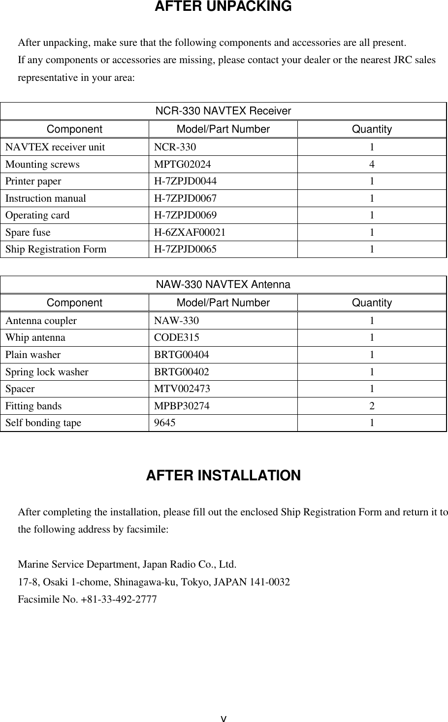


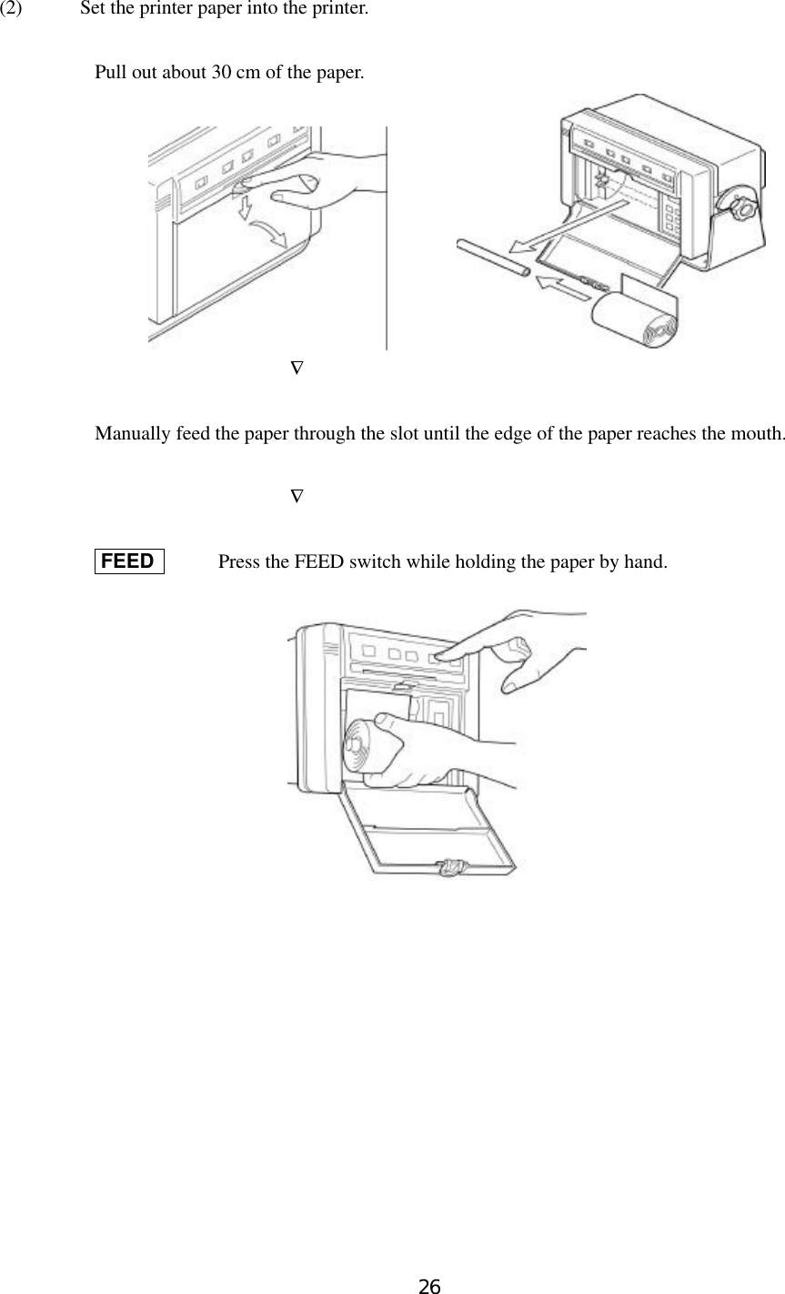
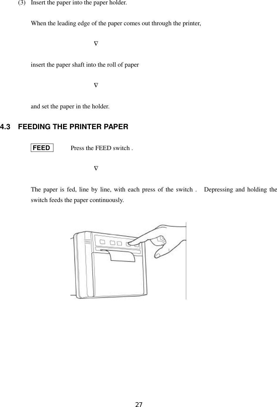
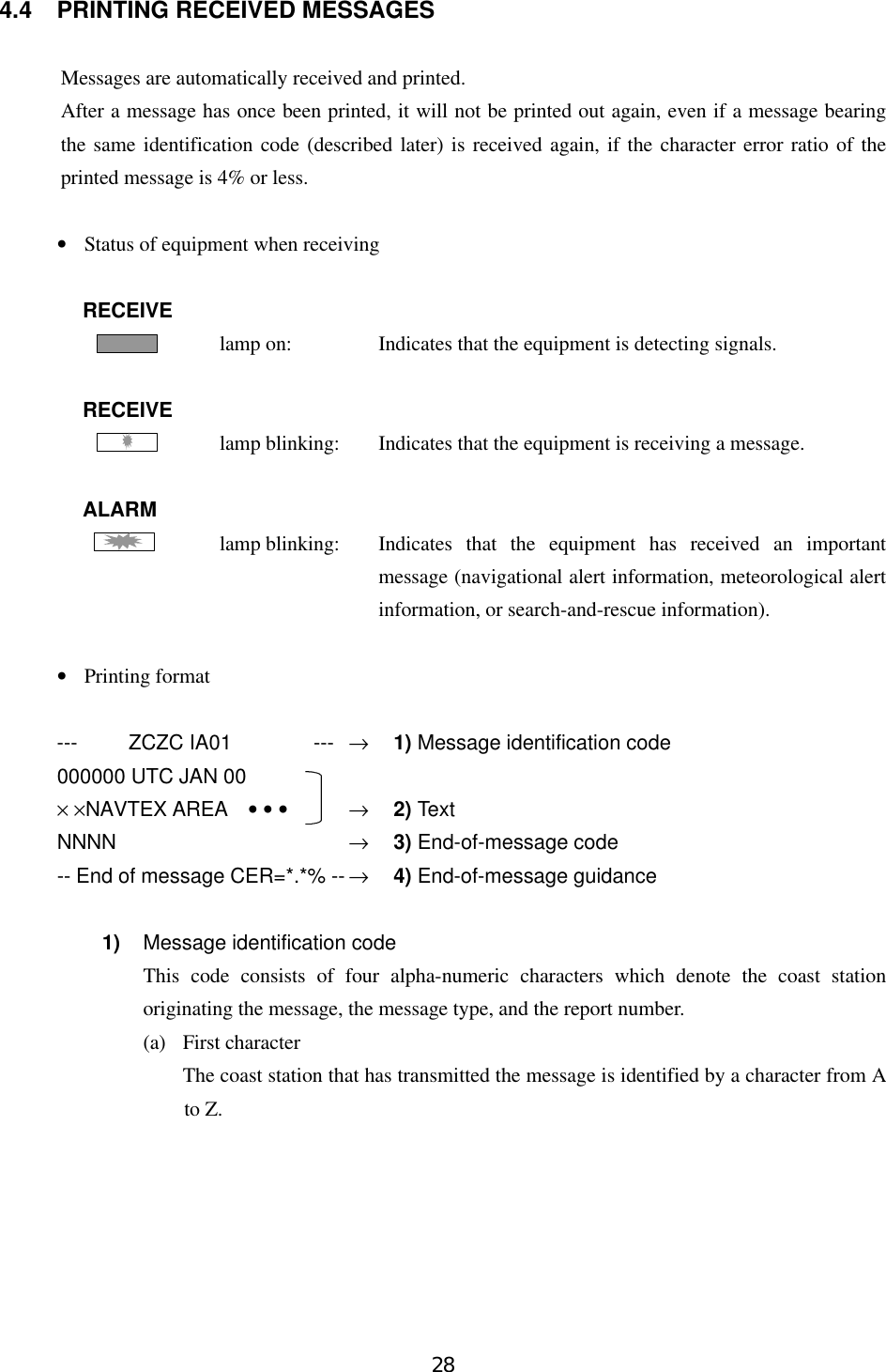
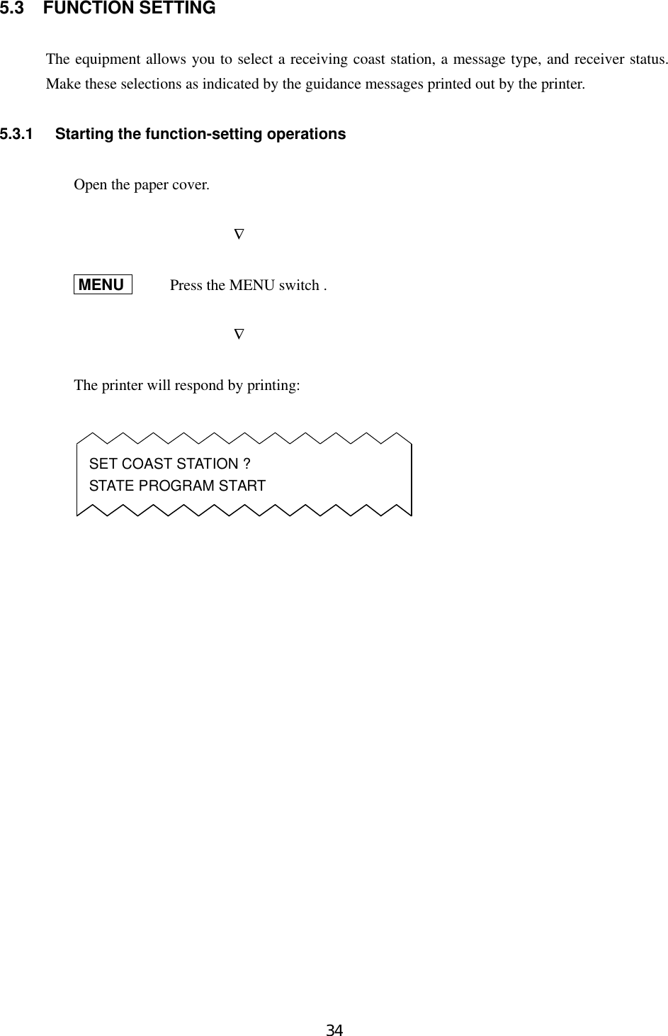
![29(b) Second characterThis character identifies the type of message.A: Navigational alertB: Meteorological alertC: Iceberg reportD: Search-and-rescue informationE: Weather forecastsF: Pilot informationG: Decca informationH: Loran informationI: Omega informationJ: Satellite navigational informationK: Electronic navigation equipment informationL: Navigational alert (Supplement to message A above)V, W, X, and Y: Special servicesZ: Indicates no information.(c) Third and fourth charactersThese characters denote the report number assigned to the message by the coaststation where the message originated.The four-character identification code is stored in memory only when the message isreceived at a character error ratio of 4% or less. When an incoming message has thesame identification code as one already stored in memory, it will not be printed.The above, however, does not apply to report number ‘00’. For report number ‘00’, thecode is not held in memory and messages are printed each time they are received.2) TextText of the message3) End-of-message codeThis code denotes the end of transmission of one message.4) End-of-message guidanceDenotes the end of the message itself. There are three types of guidance codes:(a) --- End of Message CER=∗.∗% ---Indicates that message transmission ended normally with [NNNN].(b) --- Ended by 2 Alpha CER=∗.∗% ---Indicates that the end-of-transmission code was received during message receiving.(c) --- Incomplete Message CER=∗.∗% ---Indicates that message receiving was interrupted.](https://usermanual.wiki/Japan-Radio/NCR-330/User-Guide-107998-Page-40.png)