Japan Radio NCR-330 Marine User Manual
Japan Radio Co Ltd. Marine
Instruction Manual

NCR-330
NAVTEX RECEIVER
INSTRUCTION MANUAL
i
PREFACE
Thank you for purchasing the NCR-330 JRC NAVTEX Receiver.
The NAVTEX receiver automatically receives and prints out NAVTEX service broadcasts
supplied in English.
•Before using the receiver, carefully read this INSTRUCTION MANUAL so as to fully understand the
proper usage and handling.
•Keep the INSTRUCTION MANUAL in an appropriate place so that you can readily refer to it when
necessary.
•If you are uncertain about any operations of the receiver or encounter any problems during operation,
refer to this manual. You will find solutions to common problems and useful hints and suggestions.
ii
BEFORE OPERATION
Alert Symbols
A number of alert symbols are used in this manual and labeled on the product itself to ensure safe
and proper usage, and to prevent possible injury to you or others and to avoid possible property
damage during operation or maintenance. Some of these alert symbols and their meanings are
shown below.
Before reading the remainder of this manual, familiarize yourself with the following symbols and
messages:
WARNING Indicates a situation that could result in death or serious
personal injury if ignored or if the product is mishandled.
CAUTION Indicates a situation that could result in personal injury and/or
property damage if ignored or if the product is mishandled.
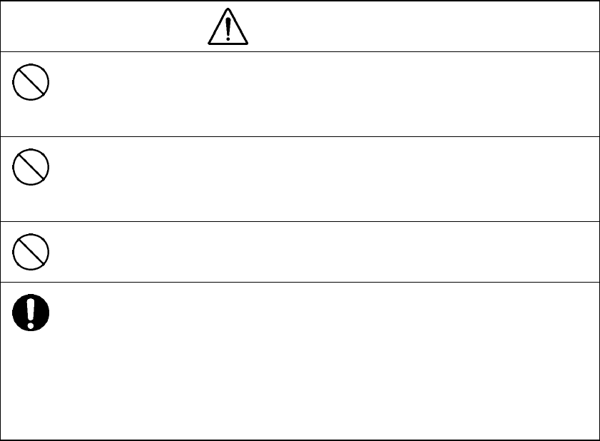
Examples of alert symbols
The triangular symbol (∆) means “caution” (danger and/or
other warning). The specific type of hazard (not specified
in this example) is depicted in the warning box.
This symbol signifies an action that is prohibited. The
specific type of prohibited action (in this example,
disassembly) is depicted in or near the symbol.
This symbol signifies a required action. The specific type
of required action (in this example, removing the power
plug from the outlet) is depicted in the symbol.
iii
OPERATING PRECAUTIONS
WARNING
Do not place heavy objects on the receiver unit. Failure to observe this
warning could result in the unit becoming unbalanced and thus causing injury if
it falls.
Do not place heavy objects on the power cable or the antenna cable. Failure
to observe this warning could result in fire, electrical shock, product trouble,
and/or receiver signal deterioration.
Do not operate at voltages other than 10.8 - 35.0 VDC. Failure to observe this
warning could result in fire, electrical shock, and/or malfunction.
If an unusual smell, smoke, or other abnormality is detected, immediately turn
off the power to the unit and then turn off the power on the power distribution
panel of the vessel. After confirming that the unusual smell, smoke, or other
abnormality has cleared up, consult your dealer or nearest JRC service/sales
representative for repair. Continued use while the abnormality persists may
cause fire and/or electrical shock.
iv
OPERATING PRECAUTIONS
CAUTION
Do not place the receiver unit on an unstable surface. If placed on an unstable
table or an uneven surface, it could fall and result in personal injury and/or
damage or malfunction of the unit.
Secure the unit sturdily using the supplied screws.
Do not expose to water or moisture. Placement on exposed decks or in humid
places may cause electrical shock or product malfunction.
Do not open or remove the cover of the unit. Touching the parts inside could
result in electrical shock. If it is absolutely necessary to check the interior of
the unit for maintenance purposes, turn off the power switch on the power
distribution panel supplying its power.
Avoid exposure to direct sunlight, heat, moisture, and dust. Failure to do so
may cause fire, malfunction, and/or deterioration of print-out quality.
Always use the JRC-recommended printer paper. The use of any other paper
may cause printer trouble and/or deterioration of print-out quality.
When cleaning, do not use benzene, alcohol, thinner, or other volatile solvents.
These solvents may damage or cause deterioration to the coated surface.
Wipe the surface lightly with a soft cloth.

v
AFTER UNPACKING
After unpacking, make sure that the following components and accessories are all present.
If any components or accessories are missing, please contact your dealer or the nearest JRC sales
representative in your area:
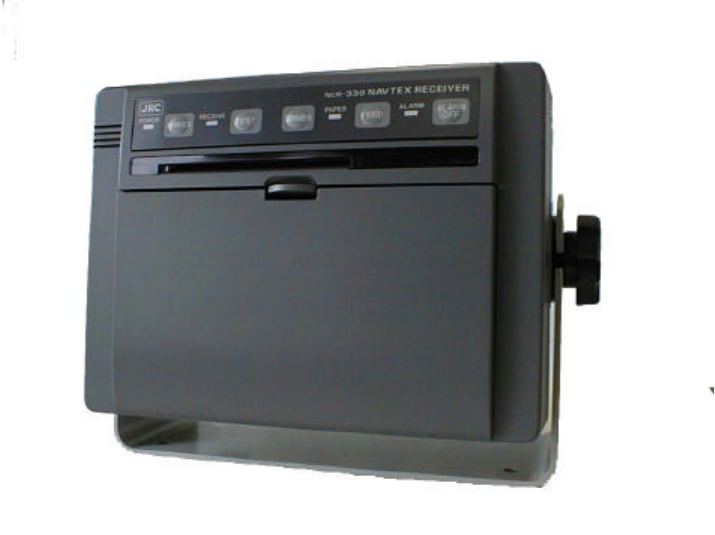
NCR-330 NAVTEX Receiver
Component Model/Part Number Quantity
NAVTEX receiver unit NCR-330 1
Mounting screws MPTG02024 4
Printer paper H-7ZPJD0044 1
Instruction manual H-7ZPJD0067 1
Operating card H-7ZPJD0069 1
Spare fuse H-6ZXAF00021 1
Ship Registration Form H-7ZPJD0065 1
NAW-330 NAVTEX Antenna
Component Model/Part Number Quantity
Antenna coupler NAW-330 1
Whip antenna CODE315 1
Plain washer BRTG00404 1
Spring lock washer BRTG00402 1
Spacer MTV002473 1
Fitting bands MPBP30274 2
Self bonding tape 9645 1
AFTER INSTALLATION
After completing the installation, please fill out the enclosed Ship Registration Form and return it to
the following address by facsimile:
Marine Service Department, Japan Radio Co., Ltd.
17-8, Osaki 1-chome, Shinagawa-ku, Tokyo, JAPAN 141-0032
Facsimile No. +81-33-492-2777
vi
EXTERNAL VIEW OF EQUIPMENT
vii
CONTENTS
PAGE
PREFACE ..........................................................................................................................................i
BEFORE OPERATION.....................................................................................................................ii
OPERATING PRECAUTIONS......................................................................................................... iii
AFTER UNPACKING........................................................................................................................v
EQUIPMENT APPEARANCE..........................................................................................................vi
GLOSSARY .....................................................................................................................................x
CHAPTER 1 EQUIPMENT OVERVIEW
SECTION
1.1 FUNCTIONS........................................................................................................1
1.2 FEATURES..........................................................................................................1
1.3 CONFIGURATION...............................................................................................2
1.4 STRUCTURE.......................................................................................................3
1.5 OVERALL FLOW CHART DIAGRAM.................................................................5
CHAPTER 2 NAMES AND FUNCTIONS OF COMPONENTS
SECTION
2.1 FRONT PANEL....................................................................................................7
2.2 REAR PANEL ....................................................................................................10
CHAPTER 3 INSTALLATION
SECTION
3.1 FASTENING THE RECEIVER ..........................................................................13
3.1.1 Site selection.........................................................................................13
3.1.2 Installation procedure............................................................................15
3.2 FASTENING THE ANTENNA............................................................................16
3.2.1 Site selection.........................................................................................16
3.2.2 Installation procedure............................................................................18
3.3 EQUIPMENT COMPONENT CONNECTION ...................................................19
3.3.1 When the power unit is to be used........................................................19
viii
3.3.2 When battery power is to be used ........................................................21
3.4 CABLE CONNECTION......................................................................................23
3.4.1 Connecting the antenna cable ..............................................................23
3.4.2 Connecting the power cable .................................................................24
CHAPTER 4 NAVTEX MESSAGE RECEIVING OPERATIONS
SECTION
4.1 TURNING POWER ON .....................................................................................25
4.2 LOADING PRINTER PAPER ............................................................................25
4.3 FEEDING THE PRINTER PAPER ....................................................................27
4.4 PRINTING RECEIVED MESSAGES ................................................................28
4.5 DEACTIVATING THE ALARM...........................................................................30
4.6 ADJUSTING THE BRIGHTNESS OF LAMPS..................................................31
4.7 TURNING POWER OFF...................................................................................31
CHAPTER 5 NAVTEX RECEIVING OPERATIONS
SECTION
5.1 DEFAULT SETTINGS........................................................................................32
5.2 RESTORING DEFAULTS..................................................................................33
5.3 FUNCTION SETTING .......................................................................................34
5.3.1 Starting the function-setting operations ................................................34
5.3.2 Selecting a receiving station .................................................................35
5.3.3 Selecting the type of message to be received......................................37
5.3.4 Selecting receiver status.......................................................................40
5.3.5 Ending function settings editing session...............................................42
5.4 STATUS PRINTING...........................................................................................43
5.5 SELF-DIAGNOSTIC TESTS .............................................................................44
5.6 COAST STATION MODE ..................................................................................45
ix
CHAPTER 6 MAINTENANCE CHECK
SECTION
6.1 MAINTENANCE CHECK...................................................................................47
6.1.1 Routine check........................................................................................47
6.1.2 Periodic check.......................................................................................47
6.1.3 Other general maintenance and check items.......................................51
6.2 IF PAPER BECOMES JAMMED .......................................................................53
6.3 FUSE/CIRCUIT BOARD REPLACEMENT .......................................................54
6.3.1 Removing the casing (Preparation for fuse/circuit board
replacement) .........................................................................................54
6.3.2 Replacing fuses.....................................................................................56
6.4 MAINTENANCE COMPONENT LISTS.............................................................57
6.4.1 Maintenance units.................................................................................57
6.4.2 Maintenance parts.................................................................................57
CHAPTER 7 AFTER-SALE SERVICES ......................................................................................58
CHAPTER 8 DISPOSAL..............................................................................................................60
CHAPTER 9 SPECIFICATIONS
SECTION
9.1 NCR-330 RECEIVER ........................................................................................62
9.1.1 Electrical specifications.........................................................................62
9.1.2 Mechanical specifications .....................................................................63
9.2 NAW-330 ANTENNA.........................................................................................64
9.2.1 Electrical specifications.........................................................................64
9.2.2 Mechanical specifications .....................................................................64
x
GLOSSARY
(1) NAVTEX Broadcasts
Maritime safety information that consists of navigational alert information, meteorological alert
information, and search-and-rescue information broadcast from coastal stations at a frequency of
518 kHz.
Alpha-numeric characters are broadcast narrow-band direct printing telegraphy in accordance with
predetermined transmission schedules.
These broadcasts cover a range of 400 nautical miles from coasts.
(2) Total Navigator (ECDIS)
Electronic chart system for navigational surveillance.
(3) Integrated Radio Communications System (IRCS) for Vessels
A system that connects GMDSS (Global Marine Disaster Safety System) equipment to a digital
interface network and provides integrated communications management using a GMDSS workstation.
1
CHAPTER 1
EQUIPMENT OVERVIEW
1.1 FUNCTIONS
οThe receiver (usually referred to as the equipment in this manual) executes the NAVTEX
function that automatically receives and prints out NAVTEX service broadcasts supplied in
English.
οThe NAVTEX function receives and prints out the various types of information broadcast at a
frequency of 518 kHz, such as: navigational alert information, meteorological alert information ,
search-and-rescue information, and other types of information. The equipment also provides a
method of programming so that you can select the type of information to be received and from
which receiving station to receive it.
1.2 FEATURES
οReceiving NAVTEX broadcasts
The equipment receives NAVTEX broadcasts automatically.
οReduced consumption of printer paper
Since the equipment has the capability of storing up to 128 message identification codes in
memory for up to 72 hours, duplicate printing of messages is avoided.
οPermanent storage of data settings
Once the types of messages to be received and their receiving stations have been set, these
settings are automatically stored into the internal memory (EEPROM) of the equipment. The
data, therefore, does not require re-setting, even after power has been turned off.
οHigh reliability based on digital demodulation
JRC’s unique digital demodulation circuit ensures high reliability.
οDual voltage supply input
The equipment can be used on either 24-VDC vessels or those with 12-VDC.
οSelf-diagnostics
The equipment contains self-diagnostic tools, making it easy to service.
οConnection to external equipment
The equipment can be used in conjunction with Integrated Radio Communications System
(IRCS) for vessels and the Total Navigator (ECDIS).
2
1.3 CONFIGURATION
The equipment consists of a main unit (NCR-330) and an antenna (NAW-330).
Although it operates on DC power, operation on AC power is also possible with an optional power
supply unit (NBG-4534A or NBG-122). Also, an external alarm buzzer can be attached so that the
alarm can be heard at remote locations when search-and-rescue information is received through
NAVTEX broadcasts.
In addition, it can be used in conjunction with the Integrated Radio Communications System (IRCS)
for vessels and the Total Navigator (ECDIS).
The overall configuration of the equipment, including major peripherals, is shown below.
NAW-330
NAVTEX Antenna
CGC-300A
External Alarm
Buzzer (optional)
NCR-330
NAVTEX
Receiver
10.8 to 35.0 VDC
NBG-122/NBG-4534A
Power Supply Unit
(100-120 VAC/220-240 VAC)
NCH-900A
IRCS
JAN-1290
ECDIS
3
1.4 STRUCTURE
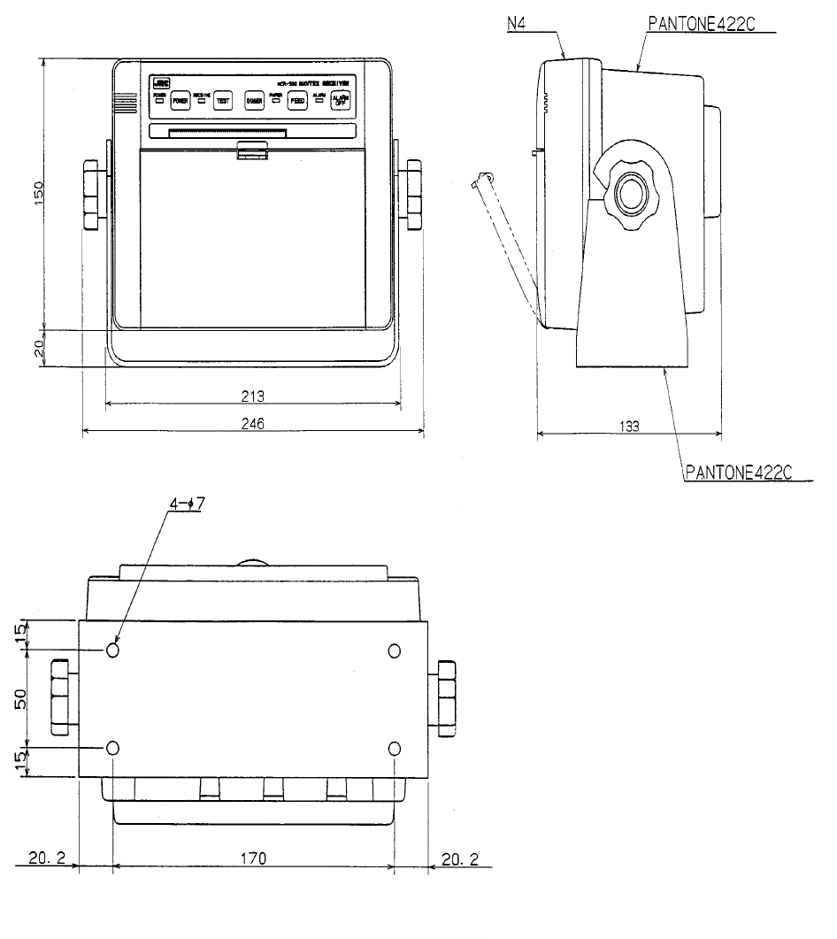
(Unit: mm)
External diagram of the NCR-330 NAVTEX Receiver
4
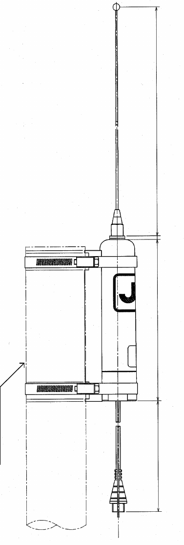
External diagram of the NAW-330 NAVTEX Antenna
(approx. 610)approx.4.5approx.190
(approx.400)
MAST φ30∼φ90
5
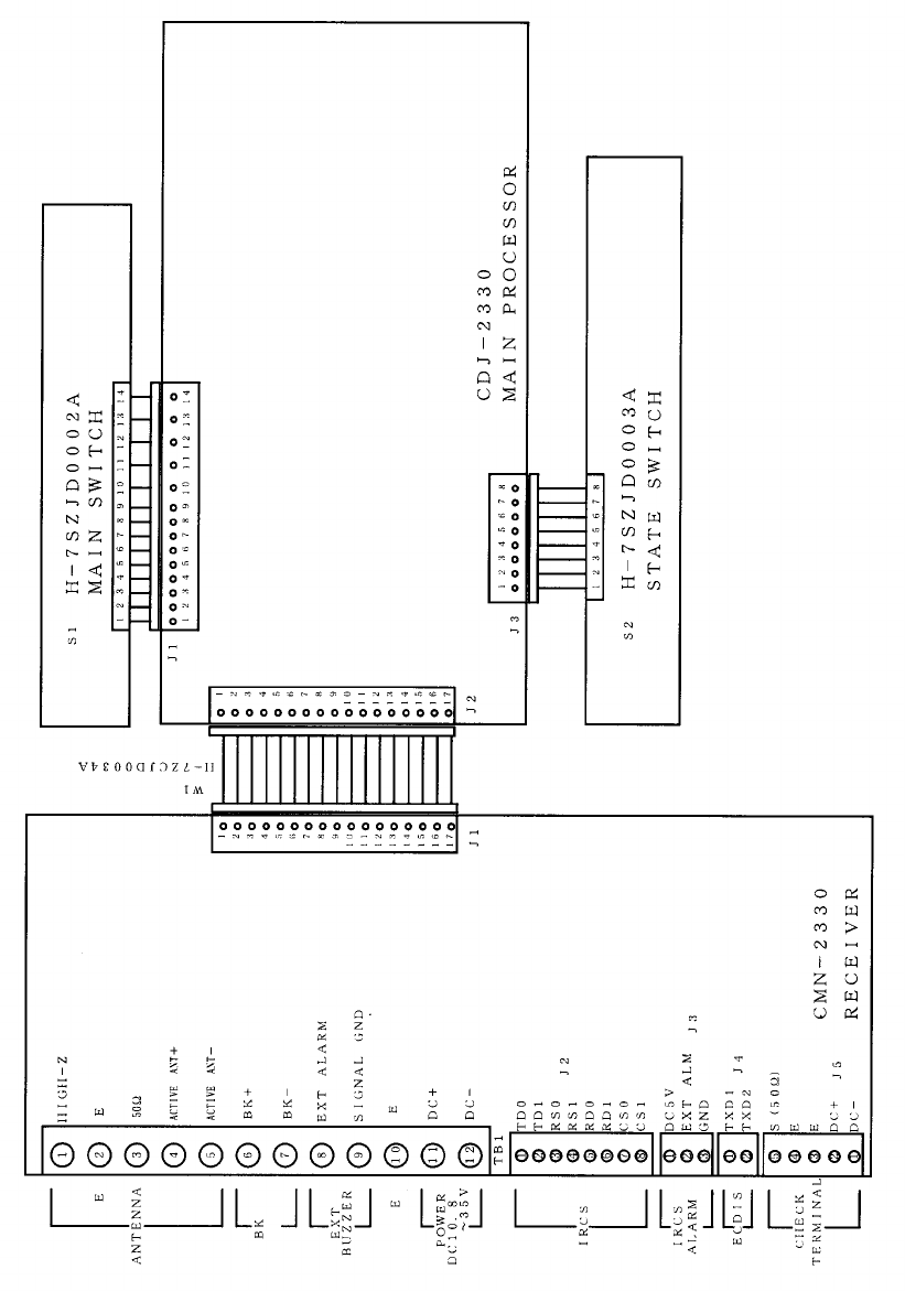
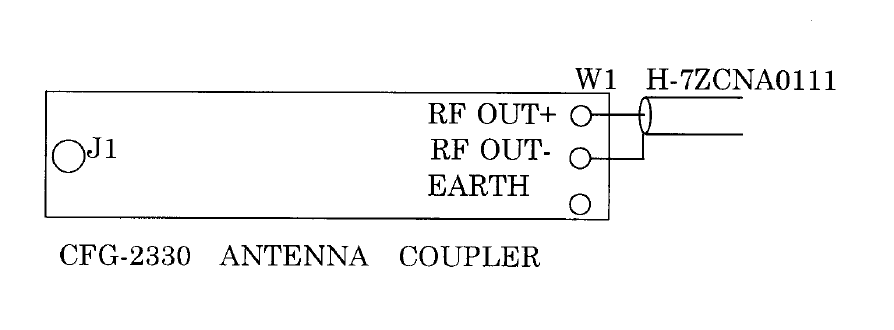
1.5 OVERALL FLOW CHART DIAGRAM
Overall Flow Chart Diagram of the NCR-330 NAVTEX Receiver
6
Overall Flow Chart Diagram of the NAW-330 NAVTEX Antenna
7
CHAPTER 2
NAMES AND FUNCTIONS OF COMPONENTS
2.1 FRONT PANEL
View of equipment with printer paper storage cover opened:
8
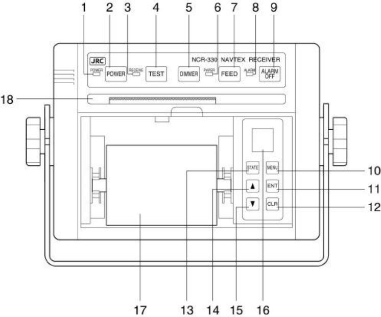
1: POWER lamp
Pressing the POWER switch activates the green POWER lamp to indicate that the power has been
turned on.
2: POWER switch
Turns the receiver on and off.
3: RECEIVE lamp
This lamp turns on during signal detection and blinks during message text receiving.
4: TEST switch
Activates the receiver’s self-diagnostic function.
5: DIMMER switch
Adjusts the brightness of the status lamps.
Each time the switch is pressed, the brightness changes in the following order:
High → Medium → Low → Off
This switch, however, does not change the brightness of the PAPER and
ALARM lamps described below.
6: PAPER lamp
This orange lamp blinks to indicate that the equipment has run short of printer paper.
7: FEED switch
Pressing this switch feeds printer paper from the printer.
Paper is fed, line by line, with each press of the switch. Pressing and holding it down feeds the
paper continuously.
8: ALARM lamp
This red lamp blinks to indicate that an alert message is being received.
9: ALARM OFF switch
This switch turns off the alarm that indicates that the equipment is receiving an alert message(s)
or running short of printer paper.

9
10: MENU switch
This switch starts/stops receiver status setting mode.
Pressing the MENU switch allows you to set the receiver status to select the receiving station and
message type in accordance to the operational instructions printed by the printer.
Press the switch again to end the setting operations.
11: ENT (enter) switch
Sets the receiver status for selection of the receiving station and message type. To select the
setting, press this switch in accordance to the operational instructions printed by the printer.
12: CLR (clear) switch
Clears the current receiver status setting of receiving station/message type. To de-select a setting,
press the switch in accordance to the operational instructions printed by the printer.
13: STATE switch
Pressing this switch prints out the currently set receiver status settings.
14: ∆ switch
Displays receiving station and message type status in ascending alphabetical order.
15: ∇ switch
Displays receiving station and message type status in descending alphabetical order.
16: Symbol Alphabet indicator
Indicates the selected letter(B1 or B2).
17: Printer paper
Messages are printed out on paper. When the paper runs short, a red line will appear at both
edges of the paper.
18: Printer
This unit prints out messages.
10
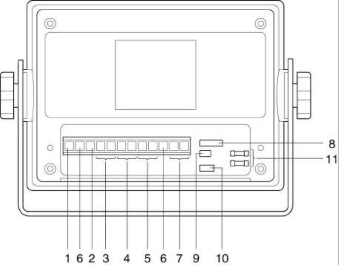
2.2 REAR PANEL
View of the equipment with rear cover removed:
11
1: High-impedance antenna terminal (HIGH-Z ANT)
Connect a wire antenna cable to this terminal.
2: 50-ohm antenna terminal (50OHM ANT)
Connect a wide-band antenna cable to this terminal.
3: NAVTEX antenna terminal (ACTIVE ANT)
Connect the antenna cable of NAW-330 Active Antenna to this terminal.
4: Key line terminals (BK+/BK-)
If needed, connect the key lines leading from the transmitter to be used to these terminals.
5: External alarm buzzer terminals (EXT.ALARM/SIGNAL.GND)
If needed, connect an optional CGC-300A buzzer to these terminals.
6: Grounding terminal (EARTH)
This terminal is for electrical grounding to the hull of the vessel.
7: Power terminals (DC+/DC-)
Connect the power supply to these terminals.
The voltage range of the power supply is from 10.8 to 35.0 VDC.
8: IRCS data input/output connector (IRCS)
This connector sends received messages to the Integrated Radio Communications System (IRCS)
for vessels and allows the NAVTEX Receiver to be set and controlled from the IRCS. Input and
output are of the current-loop specifications. Data formats comply with the JRC commands.
9: ECDIS data output connector (ECDIS)
This connector sends received messages to the Total Navigator (ECDIS). Output is of the RS-
422A specifications. The data format complies with the JRC commands.
10: Test terminals
These terminals are for in-factory testing only.
11: Fuses
A pre-arcing fuse rated at 3.15 A is connected to each the DC(+) and DC(-) lines.
12
13
CHAPTER 3
INSTALLATION
WARNING
Never carry out the receiver installation by a user.
Ask your nearest branch, business office or a dealer for inspection and repair.
3.1 FASTENING THE RECEIVER
3.1.1 Site selection
The receiver is designed so that it can be installed on either a desk, a wall, or the ceiling of the
vessel. Select an installation location that satisfies the criteria listed on the following page.
WARNING
Do not place the receiver unit on an unstable surface. If placed on an unstable
table or an uneven surface, it could fall and result in personal injury and/or
damage or malfunction of the unit.
Do not place heavy objects on the receiver unit. Failure to observe this
warning could result in the unit becoming unbalanced and thus causing injury if
it falls.
Do not place heavy objects on the power cable or the antenna cable. Failure
to observe this warning could result in fire, electrical shock, product trouble,
and/or receiver signal deterioration.
CAUTION
Do not expose to water or moisture. Placement on exposed decks or in humid
places may cause electrical shock or product malfunction.
Avoid exposure to direct sunlight, heat, moisture, and dust. Failure to do so
may cause fire, malfunction, and/or deterioration of print-out quality.
14
Avoid routing the antenna cable near other cables such as power cable,
transmission antenna cables, or radar waveguides. Close proximity to such
cables could cause interference (electronic “noise”) whereby the signal to the
receiver may deteriorate.
Criteria for site selection
(a) The distance from the magnetic compass should be at least 1 meter.
(b) The length of the grounding wire should be minimized.
(c) The installation location should be as free as possible from direct sunlight.
(d) The installation location should also be: free from excessive heat, moisture, and vibration; in
case of installation on the ceiling, free from the stagnant heat as well as the above, and; in case
of installation near a window, free from salt water spray as well as the above.
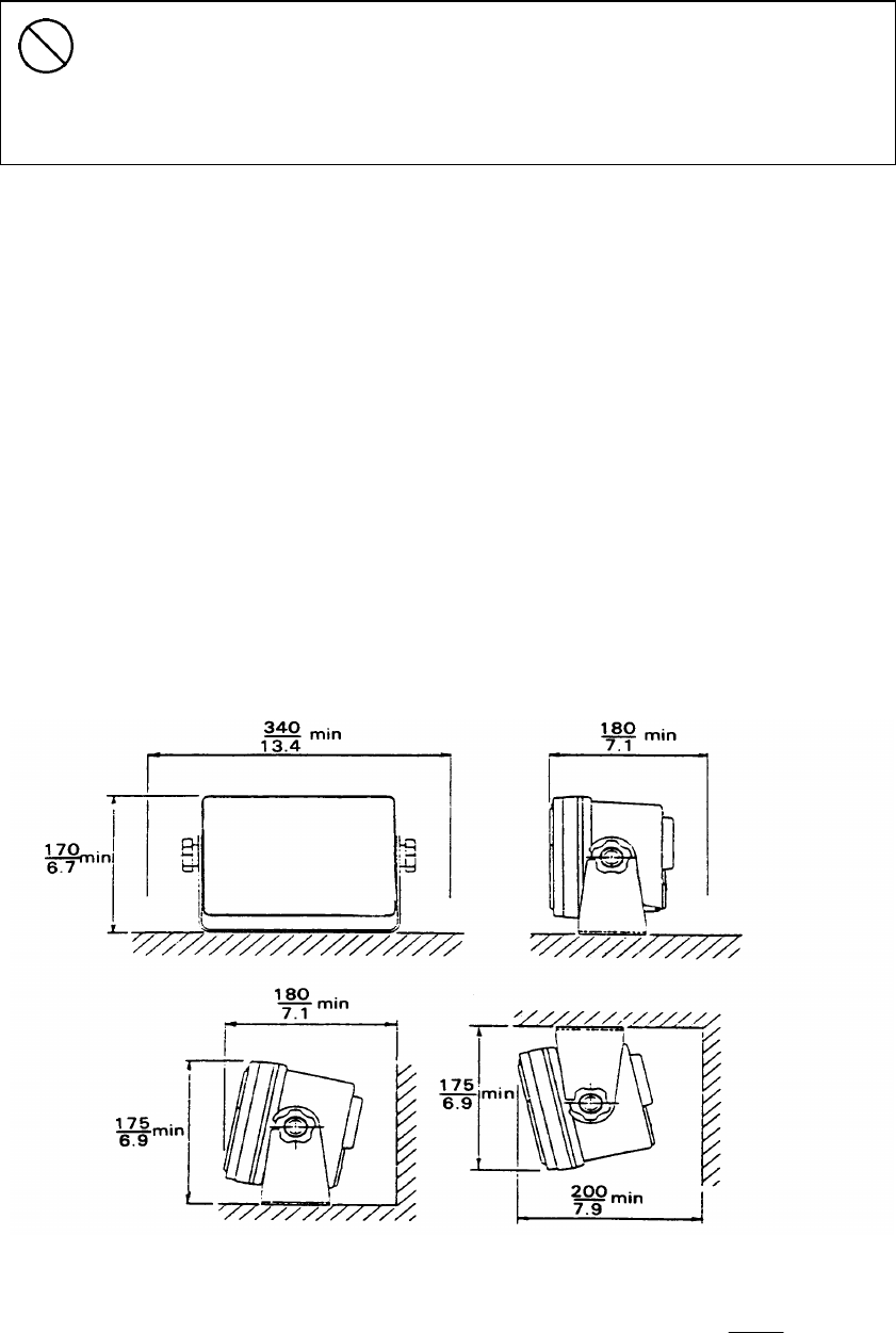
(e) The clearances as shown in the figure below should be confirmed.
The antenna cable, power cable, and grounding wire should be routed so as not to be in close
proximity with transmitter, radar, and other sources of electronic noise, as well as the cables of
these external units.
(Unit: )
Fig. 3-1 Space required for receiver installation
inch
mm
15
3.1.2 Installation procedure
The following are the procedures for installing the receiver:
(1) Loosen the knobs of the receiver and remove it from the mounting base.
(2) Screw down the mounting base at the desired location.
(3) Remount the receiver onto the mounting base and then tighten the knobs to lock the receiver in
place.
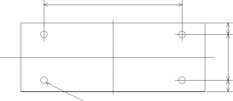
Fig. 3-2 Mounting dimensions
50
15
15
170
4-
φ
7
16
3.2 FASTENING THE ANTENNA
3.2.1 Site selection
Select an installation location that satisfies the criteria listed on the following page.
WARNING
The connectors of the antenna cable and the case mounting section of the whip
antenna must be waterproofed. Failure to do so could cause fire, electrical
shock, and/or deterioration of the signal to the receiver due to moisture or faulty
electrical contact.
Keep the whip antenna away from any obstructions within a radius of one
meter. Failure to do so could cause injure due to contact with human body.
Antenna damage might result from possible contact with the human body or .
obstructions.
CAUTION
Avoid bundling the antenna of the NAW-330 together with any other antennas.
Failure to observe this caution may cause deterioration of the signal to the
receiver due to noise radiated from other antennas. Further, noise radiated
from the antenna of the NAW-330 could cause signal deterioration to other
equipment.
Avoid routing the antenna cable near other cables such as power cable,
transmission antenna cables, or radar waveguides. Noise induced to the
antenna cable could deteriorate the receiver signal.
Do not install the whip antenna in a place exposed to strong vibration.
Antenna damage could result.
The connectors of the antenna cable must be waterproofed. Further, the
antenna connectors of the NAW-330 float from the ship earth could cause turn
on the earth lamps due to contact with the ship earth use battery power source.
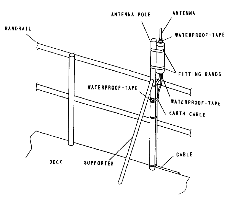
17
Criteria for antenna site
(a) Using a pole up to 9 cm in diameter and resistant to hull vibration
If the antenna is to be mounted using a pole such as a handrail, reinforce the pole by providing
stays so that the antenna can maintain its initial anti-vibration characteristics.
(b) There should be no obstructions within a radius of 1 meter of the installation location. The
presence of any obstructions may bring the whip antenna into contact with them if it is swung
significantly by the wind.
(c) The installation location should enable the antenna to be completely waterproofed.
(d) The installation location should be sufficiently distanced from the antenna of the transmitter.
Fig. 3-3 Antenna installation location
18
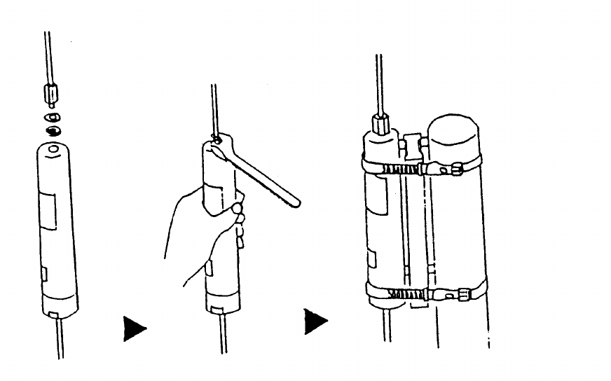
3.2.2 Installation procedure
The following are the procedures for installing the antenna:
(1) Thread the antenna element into the antenna coupler via the supplied plain washer and spring
lock washer, and tighten securely with a wrench.
(2) Fix the antenna coupler securely to the mast or perpendicular pole of the vessel using the
supplied coupler spacer and mounting bands. The maximum diameter for the pole is 9 cm.
(3) Connect the antenna cable connector and the receiver cable connector.
(4) Wind the self-fusing adhesive tape or an equivalent waterproofing tape around the following
sections:
1) Connectors
2) Whip antenna mounting case
Fig. 3-4 Antenna installation
19
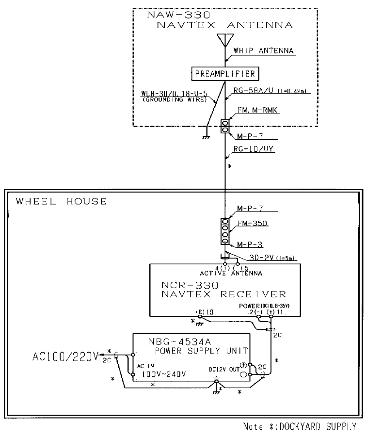
3.3 EQUIPMENT COMPONENT CONNECTION
Depending on whether the built-in or optional power unit is to be used, connect the
equipment components correctly as shown in one of the following figures:
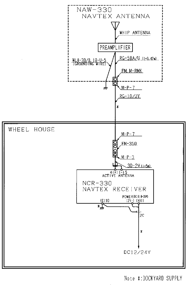
3.3.1 When the power unit is to be used
Fig. 3-5-1 Component connection diagram - Only when the power unit is to be used
20
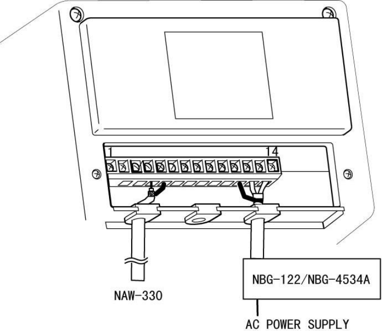
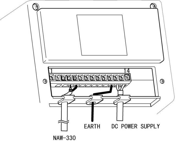
Fig. 3-5-2 Wiring the rear terminal board - Only when the power unit is to be used
21
3.3.2 When battery power is to be used
Fig. 3-6-1 Component connection diagram - Only when battry power is to be used
22
Fig. 3-6-2 Wiring the rear terminal board - Only when battery power is to be used
23
3.4 CABLE CONNECTION
Remove the cover from the rear bottom of the receiver, and connect the antenna cable, power cable,
and all other necessary cables to the terminal board. All cables can be connected using either a
Phillips or flap-tip screwdriver.
3.4.1 Connecting the antenna cable
Connect the antenna cable to the appropriate antenna terminal on the terminal board.
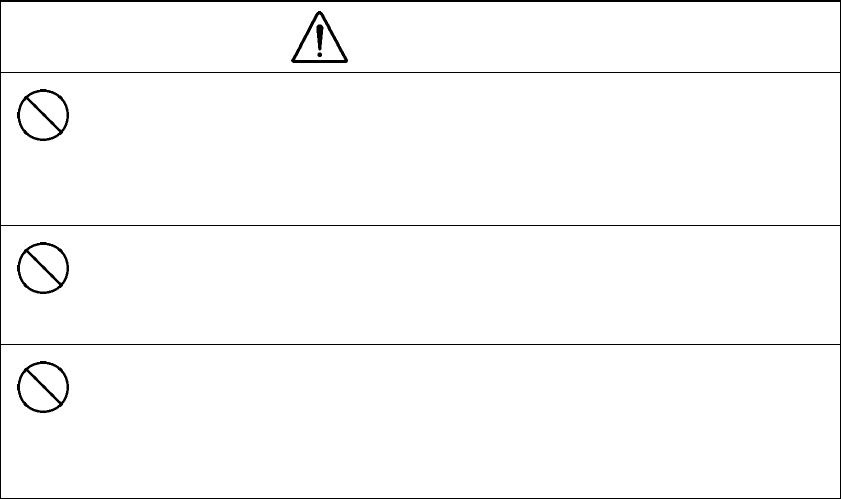
CAUTION
When connecting the antenna cable to the terminal board, be careful not to
connect the conductor wire and the shield wire to the wrong terminals.
Incorrect wiring may cause equipment and/or antenna trouble or deterioration
of the receiver signal.
Direct-current power is supplied to the antenna cable. Be careful not to short-
circuit the conductor wire and the shield wire. Short-circuiting could lead to
equipment and/or antenna failures or deterioration of the signal to the receiver.
If a ground-meter or a ground-lamp is connected to the DC power of the vessel,
do not connect the shield wire of the antenna cable to the frame grounding
terminal on the vessel. DC power to the antenna cable may cause the
ground-meter to deflect or the ground-lamp to light up.
♦ Recommended cable: Armored 50-ohm coaxial cable
Model RG-10U/Y or equivalent
Procedure
(1) Loosen the screw of the antenna cable input terminal on the terminal board.
(2) Pass the cable through the gaskets.
(3) Insert the conductor of the cable into the first hole from the left of the terminal board, and the
shield wire into the second hole.
(4) Tighten the screw to fix the cable.
24
3.4.2 Connecting the power cable
Connect the power cable to the power terminals on the terminal board.
WARNING
Do not operate at voltages other than 10.8 - 35.0 VDC. Failure to observe this
warning could result in fire, electrical shock, and/or malfunction.
CAUTION
Do not reverse the polarity of the power supply connection. This could result
in equipment malfunction.
♦ Recommended cable: Two-wire shielded cable
Model DPYC-1.25 or equivalent
Procedure
(1) Loosen the screws of the DC+ and DC- power input terminals on the terminal board.
(2) Pass the cable through the gaskets.
(3) Connect the plus wire of the cable to the DC+ terminal, and the minus wire to the DC- terminal,
and then tighten the screws to fix the cable.
25
CHAPTER 4
NAVTEX MESSAGE RECEIVING OPERATIONS
4.1 TURNING POWER ON
POWER Press and hold the POWER switch for at least two seconds.
∇
POWER The green POWER lamp will turns on.
4.2 LOADING PRINTER PAPER
Proceed as follows to set printer paper:
(1) Cut the leading edge of the paper straight across.
CAUTION
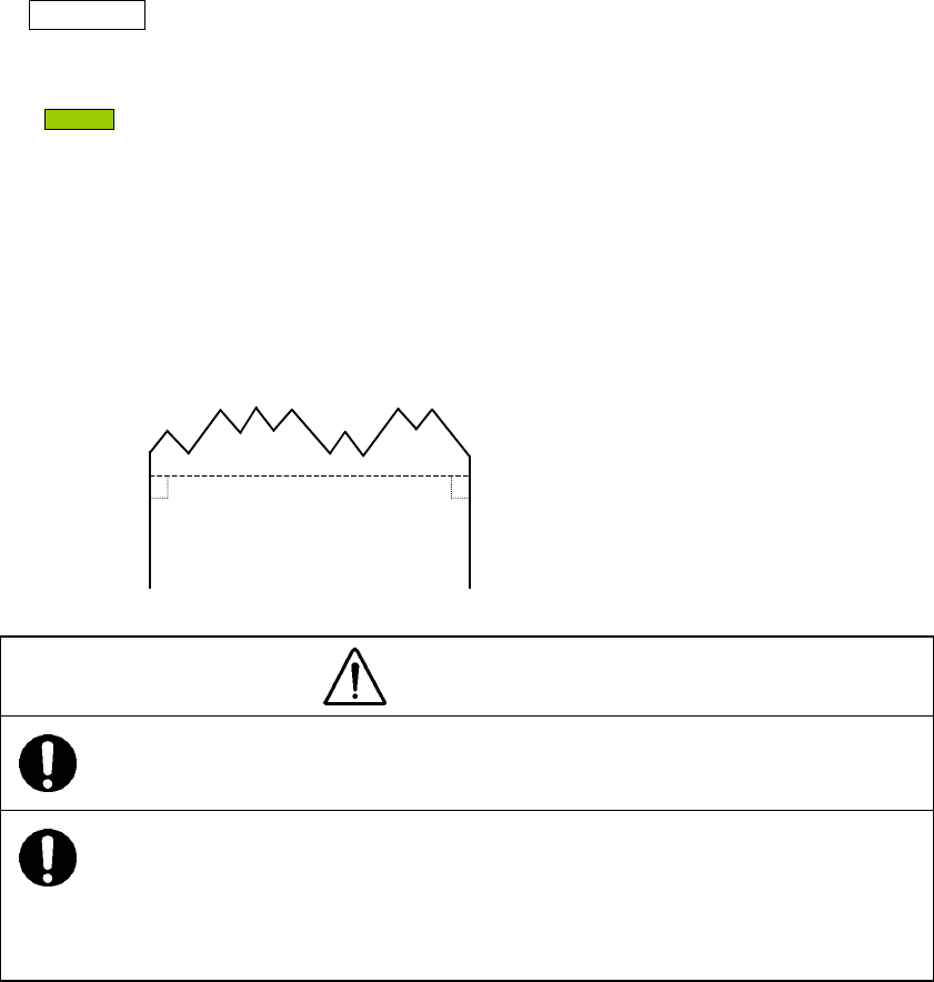
Cut the leading edge of the paper straight. Uneven cutting may cause the
paper to jam.
If the paper jams in the printer, do not use force to pull it out from the opposite
end. Forcing may result in loading trouble the next time the printer is loaded
with paper. If forcing is the only option, pull the paper out in the opposite
direction slowly and gently.
26
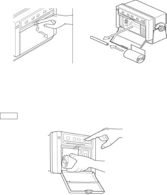
(2) Set the printer paper into the printer.
Pull out about 30 cm of the paper.
∇
Manually feed the paper through the slot until the edge of the paper reaches the mouth.
∇
FEED Press the FEED switch while holding the paper by hand.
27
(3) Insert the paper into the paper holder.
When the leading edge of the paper comes out through the printer,
∇
insert the paper shaft into the roll of paper
∇
and set the paper in the holder.
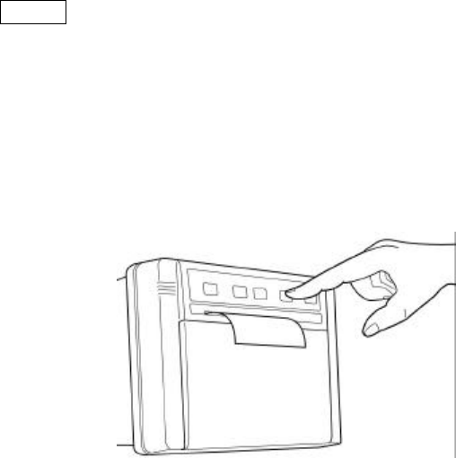
4.3 FEEDING THE PRINTER PAPER
FEED Press the FEED switch .
∇
The paper is fed, line by line, with each press of the switch . Depressing and holding the
switch feeds the paper continuously.
28
4.4 PRINTING RECEIVED MESSAGES
Messages are automatically received and printed.
After a message has once been printed, it will not be printed out again, even if a message bearing
the same identification code (described later) is received again, if the character error ratio of the
printed message is 4% or less.
•Status of equipment when receiving
RECEIVE
lamp on: Indicates that the equipment is detecting signals.
RECEIVE
lamp blinking: Indicates that the equipment is receiving a message.
ALARM
lamp blinking: Indicates that the equipment has received an important
message (navigational alert information, meteorological alert
information, or search-and-rescue information).
•Printing format
--- ZCZC IA01 --- →1) Message identification code
000000 UTC JAN 00
× ×NAVTEX AREA • • •→2) Text
NNNN →3) End-of-message code
-- End of message CER=*.*% -- →4) End-of-message guidance
1) Message identification code
This code consists of four alpha-numeric characters which denote the coast station
originating the message, the message type, and the report number.
(a) First character
The coast station that has transmitted the message is identified by a character from A
to Z.
29
(b) Second character
This character identifies the type of message.
A: Navigational alert
B: Meteorological alert
C: Iceberg report
D: Search-and-rescue information
E: Weather forecasts
F: Pilot information
G: Decca information
H: Loran information
I: Omega information
J: Satellite navigational information
K: Electronic navigation equipment information
L: Navigational alert (Supplement to message A above)
V, W, X, and Y: Special services
Z: Indicates no information.
(c) Third and fourth characters
These characters denote the report number assigned to the message by the coast
station where the message originated.
The four-character identification code is stored in memory only when the message is
received at a character error ratio of 4% or less. When an incoming message has the
same identification code as one already stored in memory, it will not be printed.
The above, however, does not apply to report number ‘00’. For report number ‘00’, the
code is not held in memory and messages are printed each time they are received.
2) Text
Text of the message
3) End-of-message code
This code denotes the end of transmission of one message.
4) End-of-message guidance
Denotes the end of the message itself. There are three types of guidance codes:
(a) --- End of Message CER=∗.∗% ---
Indicates that message transmission ended normally with [NNNN].
(b) --- Ended by 2 Alpha CER=∗.∗% ---
Indicates that the end-of-transmission code was received during message receiving.
(c) --- Incomplete Message CER=∗.∗% ---
Indicates that message receiving was interrupted.

30
4.5 DEACTIVATING THE ALARM
(a) When alert messages are received
When alert messages are received, an alarm buzzer will sound and the alarm lamp will blink.
∇
ALARM OFF Press the ALARM OFF switch.
∇
The alarm buzzer will stop sounding and alarm lamp will stop blinking.
(b) If the printer paper runs short
PAPER If the printer paper runs short, an alarm buzzer will sound and the
alarm lamp will blink.
∇
ALARM OFF Press the ALARM OFF switch.
∇
The alarm buzzer will stop sounding. The alarm lamp will continue blinking.
Supply the printer with paper.
∇
PAPER The alarm lamp will stop blinking.

31
4.6 ADJUSTING THE BRIGHTNESS OF LAMPS
DIMMER Press the DIMMER switch.
∇
Each time the switch is pressed, the brightness of the POWER and RECEIVE lamps changes in
the following order:
High → Medium → Low → Off
4.7 TURNING POWER OFF
POWER Press and hold the POWER switch for at least two seconds.
∇
POWER The green POWER lamp will go out to indicate that power has
been turned off.
32
CHAPTER 5
NAVTEX RECEIVING OPERATIONS
5.1 DEFAULT SETTINGS
When the NAVTEX receiver is operated for the first time after purchase or when the restore-
defaults sequence is executed (see next page), the equipment will be set to the following status:
Programmed Navtex Receiver Status
**Disabled Area:
-------------------------
**Disabled Message Type:
-------------------------
**Alarm(for Message type A,B&L):
Enabled
**Character size : Large
**Illumination : Bright
**Stored MSG ID :
None
33
5.2 RESTORING DEFAULTS
Restore the equipment to the factory-defaults by the following procedure:
POWER Turn power off by pressing the POWER switch.
∇
TEST While holding down the TEST switch:
∇
POWER Turn power back on by pressing the POWER switch.
∇
After the equipment has been turned back on and the printer has started operating, release the
following switch:
TEST
The printer will respond by printing:
Initialized
Navtex Receiver is Ready Ver *.*
34
5.3 FUNCTION SETTING
The equipment allows you to select a receiving coast station, a message type, and receiver status.
Make these selections as indicated by the guidance messages printed out by the printer.
5.3.1 Starting the function-setting operations
Open the paper cover.
∇
MENU Press the MENU switch .
∇
The printer will respond by printing:
SET COAST STATION ?
STATE PROGRAM START

35
5.3.2 Selecting a receiving station
After the printer has printed:
(a) If you wish to select a station, first press the ENT (enter) switch .
This allows you to select a coast station.
The display unit displays 26 coast stations (A to Z). Select the desired one from among those
displayed.
NOTE:For a list of stations and their broadcasting schedules, see Appendix 2, NAVTEX
Broadcast Stations and Schedules, at the end of this manual.
→Selecting the receiving mode
Press the ENT switch . The lamp at the bottom right of the display unit will turns
on.
→Receiving mode not selected
Press the CLR (clear) switch . The lamp at the bottom right of the display unit will
turns off.
→Changing the station
Press the ∆ switch . The display will be sorted in ascending order.
→Changing the station
Press the ∇ switch. The display will be sorted in descending order.
SET COAST STATION ?
36
→Ending selection
Press the MENU switch . The printer will print out the list of non-selected stations
followed by:
The message type can now be selected.
(b) If you do not wish to select a station, press the CLR switch .
The printer will respond with:
and to ask you to select a message type.
(c) To end the settings editing session, press the MENU switch .
The printer will respond with:
to indicate that the function settings editing session has ended.
Settings that have been selected will be stored in memory.
SET MESSAGE TYPE ?
**Disabled Area :
-------H--K---------------
SET MESSAGE TYPE ?
STATE END
37
5.3.3 Selecting the type of message to be received
NOTE Navigational alerts (A and L), meteorological alerts (B), and search-and-rescue
information (D) can not be de-selected.
After the printer has printed:
(a) To select a message type, first press the ENT switch .
This allows you to select a message type.
The display unit will show 22 message types.
Select one from among those displayed.
→Selecting the receiving mode
Press the ENT switch . The lamp at the bottom right of the display unit will turns
on.
→Receiving mode not selected
Press the CLR (clear) switch . The lamp at the bottom right of the display unit will
turns off.
→Changing the message type
Press the ∆ switch . The display will be sorted in ascending order (Z to C).
→Changing the message type
Press the ∇ switch . The display will be sorted in descending order (C to Z).
SET MESSAGE TYPE ?

38
→Ending selection
Press the MENU switch.
NOTE:The 22 types of messages that can be selected/de-selected are as follows:
C: Iceberg report
E: Weather forecasts
F: Pilot information
G: Decca information
H: Loran information
I: Omega information
J: Satellite navigational information
K: Electronic navigation equipment information
M to U: Other information
V, W, X, and Y: Special services
Z: No information
After selection of the message type, the printer will print out a list of non-selected
messages followed by:
Receiver status can now be selected.
(b) If you do not wish to select a message type, press the CLR switch.
The printer will respond with:
and ask you to select receiver status.
SET STATE ?
**Disabled Message Type :
--C----H------------------
SET STATE ?

39
(c) If you wish to end the settings editing session, press the MENU switch. The printer will
respond with:
to indicate that the function settings editing session has ended.
Settings that have been selected will be stored in memory.
STATE END

40
5.3.4 Selecting receiver status
After the printer has responded with:
(a) To select receiver status, first press the ENT switch .
This allows you to select receiver status.
The printer prints out receiver status selection items. Select one from among those printed
out.
(a-1) Alarm buzzer on/off
The alarm buzzer can be set to automatically give an alarm whenever navigational alerts
A or L or meteorological alerts B is received.
NOTE:Regardless of the above selection, the alarm will always sound when search-
and-rescue information D is received.
→Activating the alarm
Press the ENT switch. The printer will respond by printing “ON”.
→Deactivating the alarm
Press the CLR switch. The printer will respond by printing “OFF”.
SET STATE ?

41
(a-2) Character size change
The size of the characters printed out can be set to either normal size or double-width
size.
Printing at the double-width size
→Press the ENT switch. The printer will print “Large”.
Printing at the normal size
→Press the CLR switch. The printer will print “Normal”.
(b) If you do not wish to select receiver status, press the CLR switch.
The printer will respond by printing:
to indicate that the function settings editing session has ended.
STATE END

42
5.3.5 Ending function settings editing session
To end the function settings editing session, press this switch.:
MENU
The printer will print:
to indicate that the function settings editing session has ended.
Settings that have been selected will be stored in memory.
STATE END
43
5.4 STATUS PRINTING
Printing the list of current settings
You can print out a list of all the settings that are currently active.
Press this switch.:
STATE
The printer will print out a list of settings similar to this:
Programmed Navtex Receiver Status
**Disabled Area :
--------------------------
**Disabled Message Type :
--------------------------
**Alarm (for Message type A,B&L) :
Enabled
**Character size : Large
**Illumination : Bright
**Stored MSG ID :
None
44
5.5 SELF-DIAGNOSTIC TESTS
Executing self-diagnostic tests
The self-diagnostic tests begin with receiver/demodulator circuit tests and end with message-
processing tests, and confirm whether or not the internal circuits of the equipment are operating
normally.
Press this switch.:
TEST
If the self-diagnostic tests do not detect any abnormalities, data will be printed out as follows and
the alarm buzzer will sound:
Press this switch.:
ALARM OFF
The alarm buzzer will stop sounding and the alarm lamp will stop blinking.
If any abnormalities are detected, replace parts as directed in Section 6.
NOTE: The self-diagnostic tests can not be executed while the printer is in use.
------- Press “ALARM OFF ” ---------
-------- Self Test End --------
---------- ZCZC ID00 ----------
THE QUICK BROWN FOX JUMPS OVER THE
LAZY DOG 1234567890 . , ? ( ) = / + - :
NNNN
--- End of Message CER = 0.0% ---
------ Overall Test Start ------
ABCDEFGHIJKLMNOPQRSTUVWXYZ
abcdefghijklmnopqrstuvwxyz
1234567890 . , ? ( ) = / + - : * %
------ Printer Test Start ------
---- Main Processor : Good ----
---- 518kHz Receiver : Good ----
------- Self Test Start -------
45
5.6 COAST STATION MODE
The coast station mode is intended for use by coast stations in order to monitor their own NAVTEX
transmissions. When this mode is set, the receiving station and message type can not be selected.
All receiving stations and message types (A to Z) are selected by default.
Since message identification codes are not stored into the memory, the same message is printed
repeatedly.
(a) Selecting the coast station mode
Following the procedures below to set coast station mode:
POWER Turn power off by pressing the POWER switch.
∇
ALARM OFF Next, while depressing this switch., press:
∇
POWER Power will be turned back on.
∇
After the power has been turned back on and the printer has started operating, release:
ALARM OFF
The printer will respond with:
Coast Station Mode
Navtex Receiver is Ready
46
(b) Clearing the coast station mode
Following these procedures to clear the coast station mode:
POWER Turn power off by pressing the POWER switch.
∇
FEED Next, while depressing this switch., press:
∇
POWER Power will be turned back on.
∇
After the power has been turned back on and the printer has started operating, release:
FEED
The printer will respond with:
Navtex Receiver is Ready
47
CHAPTER 6
MAINTENANCE AND INSPECTION
6.1 MAINTENANCE
To maintain the equipment always in its best condition, it is important to perform maintenance
checks and record the results. Thus, potential problems can be detected early and trouble can be
avoided.
6.1.1 Daily check
Without printer paper, you cannot obtain necessary information. Therefore, check the remaining
quantity of printer paper as follows:
(1) Open the paper cover on the front panel.
(2) Check the quantity of printer paper remaining. If red lines appear at the edges of the
paper, replace it with a new roll (the red lines indicate there is one meter or less
remaining).
(3) If there is a sufficient quantity of paper, or after a new roll of paper has been set, close
the paper storage cover.
6.1.2 Periodic check
The self-diagnostic tests check the status of each function of the equipment on a per-block basis.
Conduct periodic checks as directed below.
(a) Operating procedure
See Section 5.5, Self-Diagnostic Tests, for further details.

48
(b) Self-diagnostic tests
Self-diagnostic tests begin with testing of the receiver/demodulator circuit and end with testing
of message-processing. The results are printed out, and if the tests detect no abnormalities,
the print-out will look like this:
The contents and results of diagnosis are in the following.
1) Receiver/demodulator circuit tests
A loop test of the receiver circuit is executed. When this check is completed correctly, it
prints as following:
“518kHz Receiver: Good”
If any errors are found, the following error message is printed:
“518kHz Receiver: Failed”
・・・・・・・・・・ Press “ALARM OFF”・・・・・・・・・・・・
・・・・・・・・・・・・・・・Self Test End・・・・・・・・・・・・・・・
・・・・・・・・・・・・・・・・ ZCZC ID00・・・・・・・・・・・・・・・
THE QUICK BROWN FOX JUMPS OVER THE
LAZY DOG 1234567890 . , ? ( ) = / + - :
NNNN
・・・・・・・End of Message CER = 0.0% ・・・・・・・
・・・・・・・・・・・・・ Overall Test Start ・・・・・・・・・・・・
ABCDEFGHIJKLMNOPQRSTUVWXYZ
abcdefghijklmnopqrstuvwxyz
1234567890 . , ? ( ) = / + - : * %
・・・・・・・・・・・・・・Printer Test Start・・・・・・・・・・・・・
・・・・・・・・・ Main Processor : Good・・・・・・・・・
・・・・・・・・・・518kHz Receiver : Good・・・・・・・
・・・・・・・・・・・・・ Self Test Start・・・・・・・・・・・・・・・・
・・・・・・・・ 518kHz Receiver : Failed
・・・・・・・

49
2) ROM tests
A test of the computer and memories are executed. When this check is completed
correctly, it prints as following:
“Main Processor: Good”
If any errors are found, the following error message is printed:
“Main Processor: Failed”
3) Message-processing tests
Loop tests are carried out to check for normal operation of the processes from NAVTEX
message receiving to printing. The RECEIVE and ALARM lamps blink during normal
execution of the tests.
When this check is completed correctly, it prints message identification code as following:
“ID00”
If any errors are found, the message is not printed.
・・・・・・・・・Main Processor : Failed
・・・・・・・・・
・・・・・・・・・・・ Press “ALARM OFF”・・・・・・・・・・・
・・・・・・・・・・・・・・・Self Test End ・・・・・・・・・・・・・・・
・・・・・・・・・・・・・ Overall Test Start ・・・・・・・・・・・・
50
4) Other checks by the self-diagnostic tests
a. Checking the receiving tone
During tests, if the equipment is normal, a soft tone will be heard. If this tone is not
heard, or if the tone is unusually loud, either the CMN-2330 receiver board or the
CDJ-2330 is likely to be malfunctioning.
b. Checking the alarm buzzer sound
During message-processing tests, if the equipment is normal, the alarm buzzer will
sound. This alarm can be deactivated by pressing the ALARM OFF switch. If the
alarm does not sound or if it is unusually loud, either the CMN-2330 receiver board
or the CDJ-2330 main processor board is likely to be malfunctioning.
After the alarm has sounded, if it cannot be deactivated using the ALARM OFF
switch, either the H-7SZJD0002A main switch or the CDJ-2330 main processor
board is likely to be malfunctioning.
c. Lamp tests
The lamps on the front panel blink for about three seconds prior to the start of the
message-processing tests.
During the tests, if the equipment is normal, all LEDs other than POWER will blink
at intervals of about 0.5 seconds. If blinking is abnormal, the H-7SZJD0002A main
switch or the CDJ-2330 main processor board is likely to be malfunctioning.
Also, the alphabetic display unit will display characters A to Z. If the display is
abnormal, the CDJ-2330 main processor board is likely to be malfunctioning.

51
6.1.3 Other general maintenance and check items
In addition to periodic checks by the self-diagnostic tests, it is recommended to check the
following periodically.
CAUTION
When loading the printer paper, cut the leading edge straight. Uneven cutting
may cause the paper to jam.
NOTE:If the “out of paper” alarm activates to warn of paper outage, the receiver cannot be
reset to stand-by status just by adding paper. The alarm must be cleared by
pressing the ALARM OFF switch after adding paper.

52
Check Items Contents
Antenna 1) Is the antenna mounted properly?
2) Is the whip antenna free from damage or other abnormalities?
3) Is the self-fusing adhesive tape wound properly around the antenna
connectors?
4) Is the antenna cable connected properly to the terminal board on the rear
panel?
5) Is a DC voltage between the plus and minus antenna terminals 9 volts?
NAVTEX receiver 1) Does the receiver produce the receiving tone at normal sound level?
2) Is the tone soft? Or is it a loud beeping?
Printer 1) Does the printer feed paper one line at a time with each press of the
FEED switch?
2) Are there any missing dots in the print-out?
3) Is printing density normal?
4) Are there any abnormal sounds when the printer is operating?
5) Can printer paper be added smoothly?
Out-of-paper sensor When the printer paper is cut off at the loading port, and the remaining stub
of the paper is removed from the printer:
1) Does the paper alarm lamp blink?
2) Does the paper alarm sound?
When there is no paper, and the ALARM OFF switch is pressed:
3) Does the alarm stop sounding?
4) Does the PAPER lamp remain blinking?
When printer paper is added:
5) Can the paper be fed by the FEED switch?
6) Does the PAPER lamp go out when the ALARM OFF switch is
pressed?

53
6.2 IF PAPER BECOMES JAMMED
If the paper jams near the printer head, ask your nearest branch, business office or a dealer for
inspection and repair.
CAUTION
If the paper in the printer jams, do not continue pressing the FEED switch.
When loading paper into the printer, cut the leading edge straight. Uneven
cutting may cause the paper to jam.
54
6.3 FUSE/CIRCUIT BOARD REPLACEMENT
6.3.1 Removing the casing (Preparation for fuse/circuit board replacement)
WARNING
The power switch on the power distribution panel must be turned off during
disassembly of the equipment. Failure to observe this warning could cause
electrical shock and/or malfunction.
CAUTION
Wiring must be disconnected from the terminal board during disassembly of
the equipment. Failure to observe this caution could cause electrical shock
and/or malfunction.
The procedure for removing the case is as follows:
(1) Turn power off.
(2) Cut off power to the receiver by turning off the power switch on the power distribution panel.
(3) Remove screws 1 and 2 and then remove the rear cover.
(4) Disconnect the wiring from the terminal board on the rear panel of the equipment.
(5) Remove screws 4 , 5 , 6 , and 7 .
(6) Holding both sides of the casing, press terminal strip 9 with the thumb, and lift off the
casing.
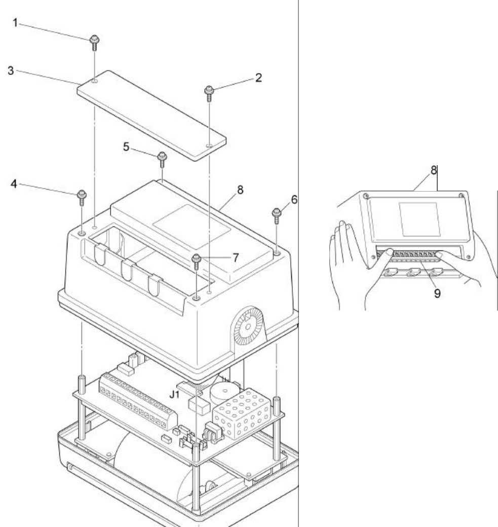
55
Fig. 6-3 Removing the casing
56
6.3.2 Replacing fuses
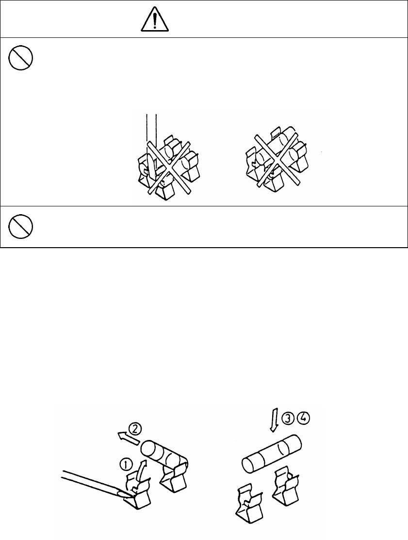
WARNING
The power switch on the power distribution panel must be turned off during
replacing a fuse. When replacing a fuse, use extreme caution not to bring it
into contact with adjacent ones. Short-circuiting due to making contact may
cause power and/or circuit board damage.
Use only MF51NN-3.15A fuses (normal pre-arcing type, rated at 3.15 A). The
use of other fuse may cause fire and/or damage.
The replacement procedure is as follows:
(1) Lift one end of the blown fuse using a tool such as a thin tip screwdriver.
(2) Remove the fuse.
(3) Place a new fuse in the fuse holder.
(4) Push the new fuse into position.

57
6.4 MAINTENANCE COMPONENT LISTS
6.4.1 Maintenance units
NCR-330 NAVTEX Receiver Board Unit
Name of the unit Model number JRC part code
Receiver board CMN-2330 CMN-2330
Main processor board CDJ-2330 CDJ-2330
Main switch H-7SZJD0002A 7SZJD0002A
State switch H-7SZJD0003A 7SZJD0003A
NAW-330 NAVTEX Antenna Board Unit
Name of the unit Model number JRC part code
Antenna coupler CFG-2330 CFG-2330
6.4.2 Maintenance parts
Parts for the NCR-330 NAVTEX Receiver
Part name Model number JRC part code
Fuse MF51NN-3.15A 5ZFAD00227
Front panel MPBC32211 MPBC32211
Printer paper H-7ZPJD0044 7ZPJD0044
Parts for the NAW-330 NAVTEX Antenna
Part name Model number JRC part code
Whip antenna CODE315 MPAE30101
58
CHAPTER 7
AFTER-SALES SERVICE
♦ When Requesting Repair
(1) If you suspect that a problem has occurred, take the appropriate remedial action after
completing the following diagnostic :
a) Check the rear terminal board of the equipment for loose or disconnected cables.
b) Check that the required voltage is supplied to the power input terminals on the rear
terminal board of the equipment. The required voltage ranges from 10.8 to 35.0 VDC.
c) Check the antenna for damage.
d) Check the equipment interior for blown-out fuses.
e) Check for loose or disconnected cables between the internal components of the
equipment.
f) Check the relay connectors of the antenna cable for loose or disconnected cable.
(2) If the above checks uncover any abnormalities, stop operations of the receiver immediately
after that contact our dealer, service representative or JRC sales.
•Repairs within the warranty period will be performed free of charge in accordance with the
provisions of the relevant specification.
•After the expiry of the warranty period, if the corresponding function can be restored by repair,
out-of-warranty repairs will be performed at your request. Please note that this repair is not free
of charge.
•When requesting repair, give the following information to the service:
- Product name, model number, date of manufacture, and serial number
- How and why the trouble occurred
1) The nature of the problem, and what happened as a result?
2) The state or type of operation when the trouble occurred?
3) Installation status of the equipment when the trouble occurred? (conditions of
wiring, electrical grounding, and so on).
4) Was any unusual or abnormal condition observed during operation before the trouble
occurred?
- Name, address, and phone number of your company or institution, and your name
59
♦Optional Maintenance Checks
Over a period of time, the performance of various components will deteriorate. The actual rate
of deterioration will vary according to the operating conditions and environment. It is therefore
recommended for your equipment to undergo optional maintenance and servicing in addition to
your own checks.
Please contact your dealer or JRC sales or service representative for optional services.
A fee is charged for these services.
If you have any questions about after-sale services, please contact your dealer or JRC sales or
service representative.
♦JRC Sales/Service Representatives
See the List of JRC Product Dealers and JRC Sales/Service Representatives at the end of this
manual.
60
CHAPTER 8
DISPOSAL
If this product is to be disposed of, process it in accordance with the legal regulations of the local
government having jurisdiction. For further details, please contact your dealer or JRC sales/service
representative or the local government having jurisdiction.
Materials⋅ ⋅ ⋅See mechanical parts list of appendix1 at the appendix of this manual.
61

62
CHAPTER 9
SPECIFICATIONS
9.1 NCR-330 RECEIVER
9.1.1 Electrical specifications
(1) NAVTEX receiver unit
a. Receiver
Receiving frequency 518 kHz
Receiving scheme STRAIGHT
Receiving mode F1B
Gain Max. character error ratio: 1% at an antenna input of 1µV
Antenna input Special antenna (NAW-330)
BK 12 VDC or 24 VDC
External alarm interface Open-collector type
Max: 500 mA at 35VDC
Recommended product: CGC-300A
Max. power consumption: 20 mA
Audio output level: 85 dB/m
Receiving format 7-bit error detection code based on the NAVTEX
broadcasting format
b. Printer
Printing scheme Thermosensitive 7 × 6 or 7 × 5 dot matrix
Total characters/line 35 or 40
Printer paper TF50KS-E3, 80 mm × 60 mm across × 40 m
Out-of-paper warning Alarm buzzer
Operating panel lamp blinking
Red end-of-paper line marks on printer paper (the red lines
indicate there is one meter or less remaining).
c. Control switches
Power on/off
Coast station selection
Message type selection
Receiver status selection
Alarm buzzer manual turn-off
Receiver status information printing
63
Brightness control
Self-diagnostic tests
Paper feeding
d. Display/indicator unit
Power-on indicator
Visual alarm on important message receiving
Out-of-paper alarm
Receiving indicator
(2) Power unit
Input voltage 12 to 24 VDC(Tolerance +30%,-10%)
Power consumption (Standby) at 12 VDC: Approx. 4 W
(Operating) at 12 VDC: Approx. 6 W (max.)
(Standby) at 24 VDC: Approx. 5 W
(Operating) at 24 VDC: Approx. 7 W (max.)
9.1.2 Mechanical specifications
(1) Minimum and maximum temperature range
Operating: -15 to +55°C
Storage: -25 to +75°C
(2) Relative humidity Up to 95% at 40°C
(3) Dimensions 246 mm wide×170 mm high×131.5 mm deep
(with mounting base)
(4) Installation Wall-mounting, desk-mounting, or ceiling-mounting
(5) Mass 2.0 kg (with mounting base)
64
9.2 NAW-330 ANTENNA
9.2.1 Electrical specifications
Receiving frequency 518 kHz
Bandwidth 5 kHz
Gain Min. antenna coupler output: 60 dBµV
(at an electric field intensity of 60 dBµV/m)
Power consumption 6 mA at 9 VDC
Impedance 50Ω
9.2.2 Mechanical specifications
Installation Mountable on a pole up to 9 cm across
using the supplied mounting band.
Mass 0.5 kg