Japan Radio NCR-333 Marine NAVTEX Receiver User Manual
Japan Radio Co Ltd. Marine NAVTEX Receiver
UserManual.wiki
>
Japan Radio
>
NCR 333 User Manual
Instruction Manual
Navigation menu
Upload a User Manual
Namespaces
Wiki Guide
HTML
PDF
Info
Views
User Manual
Discussion / Help
Navigation
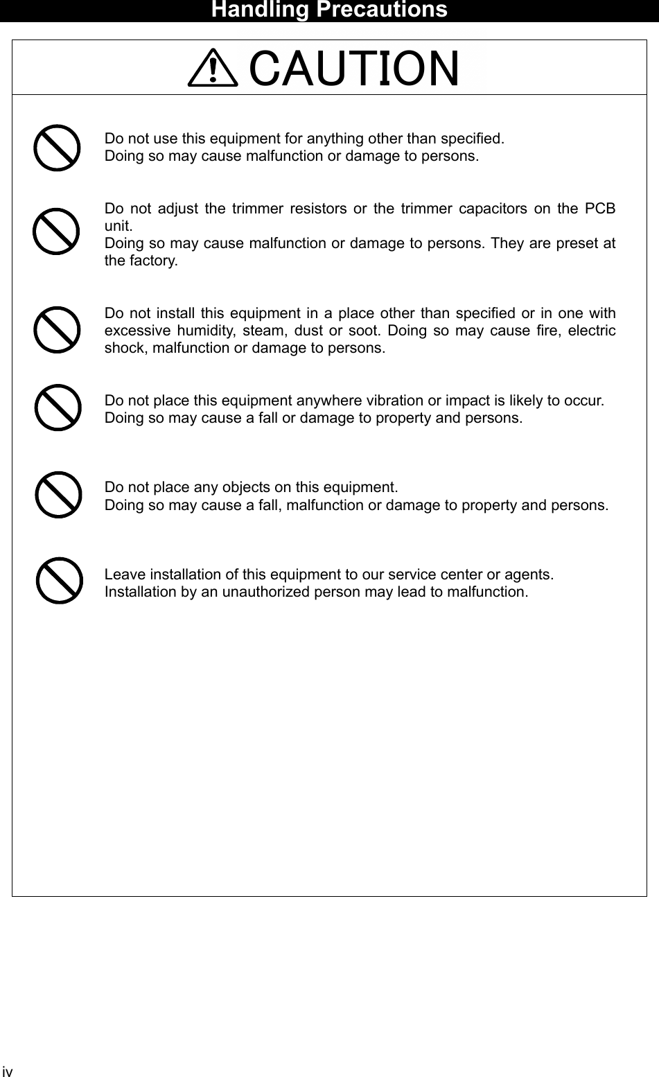
![4-4 4.1.6 Setup screen To display “Main menu”, press the MENU key. Refer to “6.3 MAIN MENU” for NCR-333 settings MAIN MENU ⅤⅢ 1.RX STATION_ 2.MESSAGE TYPE 3.DISPLAY 4.NAVTEX 5.MAINTENANCE 6.LANGUAGE: ENGLISH [EXIT]](https://usermanual.wiki/Japan-Radio/NCR-333/User-Guide-571910-Page-30.png)

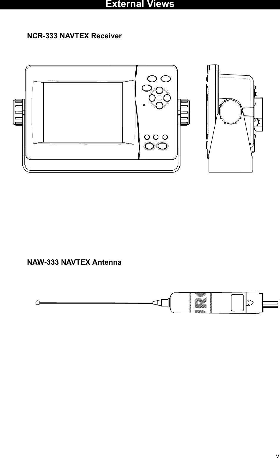
![6-1 6. OPERATION 6.1 Menu Tree [DSPL] KeyPOS/TIMESAVE MSG LISTMSG LIST 2MSG LIST 1[DSPL] key(Power ON)MSG VIEW[ ], [ENT] Key [ ], [ENT] Key [ ], [ENT] Key [ ], [ENT] Key [MENU] [CLR] [MENU][ ], [CLR] Key [ ], [CLR] Key [ ], [CLR] Key [ ], [CLR] KeyMAIN MENU 1. RX STATION 1. RX MODE2. OPERATING FREQ.3. AUTO MODE SETTING 1. STATION (AUTO)4. MANUAL MODE SETTING 1. STATION (MANUAL)2. MESSAGE TYPE 1. MSG TYPE3. DISPLAY 1. CONTRAST2. DIMMER - MAXIMUM - TYPICAL - MINIMUM3. BUZZER - ALARM MSG - RECEIVED MSG - NAVTEX ALARM - CLICK4. LOCAL TIME5. USER KEY SETTING 1. USER KEY6. POS/TIME DISP. SET4. NAVTEX 1. CHARACTER SIZE2. CER DISP.SETTING3. MESSAGE SCROLL4. MESSAGE SPEED5. PRINTER PROPERTY - DATA OUT - DATA FORMAT - BAUDRATE - FLOW CONTROL - PRINT DIRECTION5. MAINTENANCE 1. SELF DIAGNOSIS 1. SELF DIAGNOSIS2. LCD DIAGNOSIS3. SELF DIAGNOSIS LOG2. NAVTEX ALARM 1. ALARM HISTORY3. STATUS 1. STATUS4. PORT MONITOR 1. PORT SELECTION 1. MONITOR screen2. PORT LOG 1. LOG screen5. SOFTWARE VERSION - PROGRAM - LANGUAGE - OPTION6. LANGUAGE[ENT[MENU] Key](https://usermanual.wiki/Japan-Radio/NCR-333/User-Guide-571910-Page-33.png)
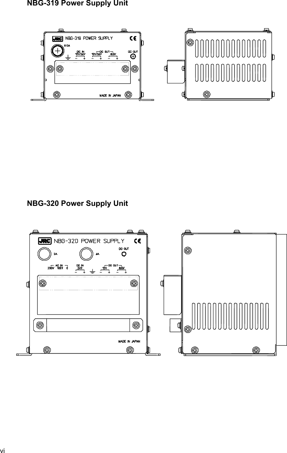
![6-3 6.2.1.2 Start up (Abnormal-1) When any result of self-diagnosis is “NG”, a message text screen does not change automatically. And the caution sentence as shown in the following figure is displayed on the self-diagnostic screen. In this case, press the CLR key. The latest message text screen appears. When “NG” is in a result, be sure to carry out self diagnosis in the “MAIN MENU” after displaying the message text screen. Check the detailed result of the “NG” item. (Refer to “6.3.5.1 Self diagnosis”) 6.2.1.3 Start up (Abnormal-2) When the result of “ROM CHECK” is “NG”, the sub screen may be displayed as shown in the following figure. Be sure to select "[START]" on the sub screen. In this case, although NCR-333 operates, the screen cannot display in languages other than English. [START]: The latest message text screen is displayed. [INST]: The software installation screen is displayed. When the installation screen is displayed, press and hold the PWR/CONT and DIM keys simultaneously until the power is turned off. Turn on the power, and restart the NCR-333. Contact our service center or agents. * SELF-DIAGNOSING... ROM CHECK: OK RAM CHECK: OK ANT CHECK: OK LOOP TEST: NG PLEASE CARRY OUT ‘SELF-DIAGNOSIS’ IN MAINTENANCE MENU. [PRESS ‘CLR’ KEY] * SELF-DIAGNOSING... ROM CHECK: NG RAM CHECK: OK ANT CHECK: OK LOOP TEST: OK PLEASE CARRY OUT ‘SELF-DIAGNOSIS’ IN MAINTENANCE MENU. [PRESS ‘CLR’ KEY] *OPTION DAT.ERR* STARTING NAVTEX? OR RE-INSTALL [START] [INST] [Option language data error] *LANGUAGE DAT.ERR* STARTING NAVTEX? OR RE-INSTALL [START] [INST] Caution Caution](https://usermanual.wiki/Japan-Radio/NCR-333/User-Guide-571910-Page-35.png)
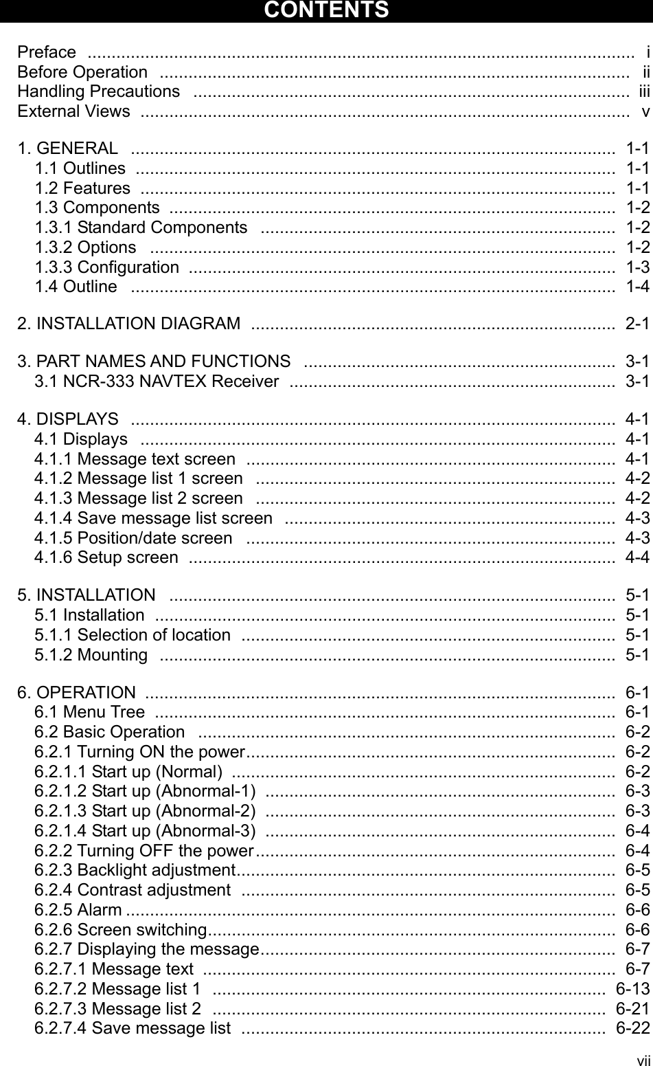
![6-4 6.2.1.4 Start up (Abnorma-3) When the following screen is displayed, press and hold the PWR/CONT and DIM keys simultaneously until the power is turned off. Contact our service center or agents. 6.2.2 Turning OFF the power Press and hold the PWR/CONT and DIM keys simultaneously for one second until the power is turned off. _ CHECK SUM _ _ COMPARING ERROR ! _ _ _ _ PLEASE RE-INSTALL _ _ THE PROGRAM. _ PLEASE RESTART AFTER SOFTWARE UPDATE PRESS AND HOLD [DIM]+[PWR] Caution DIM PWR CONT](https://usermanual.wiki/Japan-Radio/NCR-333/User-Guide-571910-Page-36.png)
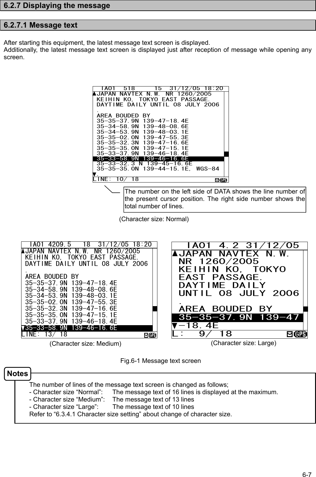
![6-8 The message type and the message identification codes are as follows. The message identification codes displayed on upper-left side of the message text screen (“lA01” in the above example) indicates the message type. These codes consist of four alpha-numeric characters which denote the coast station originating the message, the message type and the report number. a. First character The coast station that has transmitted the message is assigned by a character from A to Z. b. Second character This charactger identifies the type of message. [A] Navigational warnings [B] Meteorological warnings [C] Ice reports [D] Search and rescue information, and pirate attack warnings [E] Meteorological forecasts [F] Pilot service messages [G] AIS [H] LORAN-C messages [J] SATNAV messages [K] Other electronic navaid messages [L] Navigational warnings (Additional to letter “A”) [V - Y] Special services [Z] QRU (No messages on hand) c. Third and fourth characters These characters denote the report number assigned to the message by the coast station where the message originated. The four-character identification code is stored in memory only when the message is received at a character error rate (CER) of 33 % or less. When an incoming message has the same identification code as one already stored message at CER of 4 % or less in memory (about 70 hours), it will not be displayed and stored. The above, however, does not apply to report number ‘00’. For report number ‘00’, the code is not held in memory and messages are displayed and stored each time they are received. a. Clear the unread mark The message text is displayed after the message has been received. Unread mark on the status bar shows unread messages has been received. 1) If the ENT key is pressed, the caution sentence disappears, and this message changes to read message. If all messages are read messages, the “ ” mark of status bar is cleared. - Unread messages can also be checked on the message list 1 or 2. (Refer to “6.2.7.2” or “6.2.7.3”) Be sure to clear the unread mark after reading a message. Procedures Notes IA01 518 15 31/12/05 18:20 JAPAN NAVTEX N.W. NR 1260/2005 KEIHIN KO, TOKYO EAST PASSAGE. DAYTIME DAILY UNTIL 08 JULY 2006 . AREA BOUDED BY 35-35-37.9N 139-47-18.4E 35-34-58.9N 139-48-08.6E 35-34-53.9N 139-48-03.1E 35-35-02.0N 139-47-55.3E 35-35-32.3N 139-47-16.6E 35-35-35.0N 139-47-15.1E 35-33-37.9N 139-46-18.4E 35-33-58.9N 139-46-16.6E 35-33-32.3 N 139-45-16.6E 35-35-35.0N 139-44-15.1E, WGS-84THE MSG WAS RECEIVED. PRESS[ENT]KEYLINE: 10/ 18 Unread markCaution sentence](https://usermanual.wiki/Japan-Radio/NCR-333/User-Guide-571910-Page-40.png)
![6-9 b. Read the message Screen scrolling 1 The ‘ ‘ (‘ ‘) mark is displayed when the message text scroll downward (upward) is available. 1) To move the cursor up/down to the next line, press the ▲ ▼ key. (Cursor scrolls one by one in the message text.) 2) To scroll the next page of the message text downward (upward) when cursor is on the bottom (top) line, press the ▼ (▲) key. Screen scrolling 2 To skip to the next / previous message text screen is available. 1) To display to the previous / next screen, press the key. c. Read the other message Read the new message The new message can be displayed on the message text screen. 1) Press the * key. The sub screen appears. 2) Select the “[NEXT MSG]”, and press the ENT key. 3) The new message is displayed. - “[NEXT MSG]” can be selected when there is new message. Read the old message The old message can be displayed on the message text screen. 1) Press the * key. The sub screen appears. 2) Select the “[PREV. MSG]”, and press the ENT key. 3) The old message is displayed. - “[PREV.MSG]” can be selected when there is old message. IA01 518 15 31/12/05 18:20 JAPAN NAVTEX N.W. NR 1260/2005 KEIHIN KO, TOKYO EAST PASSAGE. DAYTIME DAILY UNTIL 08 JULY 2006 . AREA BOUDED BY 35-35-37.9N 139-47-18.4E 35-34-58.9N 139-48-08.6E 35-34-53.9N 139-48-03.1E 35-35-02.0N 139-47-55.3E 35-35-32.3N 139-47-16.6E 35-35-35.0N 139-47-15.1E 35-33-37.9N 139-46-18.4E 35-33-58.9N 139-46-16.6E 35-33-32.3 N 139-45-16.6E 35-35-35.0N 139-44-15.1E, WGS-84. LINE: 10/ 18 IA01 518 15 31/12/05 18:20 JAPAN NAVTEX N.W. NR 1260/2005 KEIHIN KO, TOKYO EAST PASSAGE. DAYTIME DAILY UNTIL 08 JULY 2006 . AREA BOUDED BY 35-35-37.9N 139-47-18.4E 35-34-58.9N 139-48-08.6E 35-34-53.9N 139-48-03.1E 35-35-02.0N 139-47-55.3E 35-35-32.3N 139-47-16.6E 35-35-35.0N 139-47-15.1E 35-33-37.9N 139-46-18.4E 35-33-58.9N 139-46-16.6E 35-33-32.3 N 139-45-16.6E 35-35-35.0N 139-44-15.1E, WGS-84. LINE: 10/ 18 * SET UP * [NEXT MSG] [PREV. MSG] [SAVE MSG] [PRINT OUT] DATA OUT Procedures Procedures Procedures Notes Notes Procedures](https://usermanual.wiki/Japan-Radio/NCR-333/User-Guide-571910-Page-41.png)
![6-10 d. Save the message Save the message The currently open message can be saved. The saved message is permanently stored in the data memory. 1) Press the * key. The sub screen appears. 2) Select the “[SAVE MSG]”, and press the ENT key. 3) “ARE YOU SURE?” is displayed. Select the “[OK]”, and press the ENT key. (“NOW SAVING...” is displayes on the sub screen.) To return to the sub screen (SET UP), select “[CANCEL]” and press the ENT key. 4) After message saving has been completed, press the ENT key or the CLR key. - The message that is not saved (the stored message) is automatically erased from the data memory about 70 hours after receiving. - 50 messages of an average length of 500 characters can be saved in each channel. The message cannot be saved When the saved message in the data memory is full, the sub screen is displayed as shown in the following figure, and the status bar shows which channel cannot be saved ( mark). Refer to “c. Put a check mark” (6.2.7.2 Message list 1) for explanation of the display of the status bar. Save again after deleting the message in save message list when unable to save a message. IA01 518 15 31/12/05 18:20 JAPAN NAVTEX N.W. NR 1260/2005 KEIHIN KO, TOKYO EAST PASSAGE. DAYTIME DAILY UNTIL 08 JULY 2006 . AREA BOUDED BY 35-35-37.9N 139-47-18.4E 35-34-58.9N 139-48-08.6E 35-34-53.9N 139-48-03.1E 35-35-02.0N 139-47-55.3E 35-35-32.3N 139-47-16.6E 35-35-35.0N 139-47-15.1E 35-33-37.9N 139-46-18.4E 35-33-58.9N 139-46-16.6E 35-33-32.3 N 139-45-16.6E 35-35-35.0N 139-44-15.1E, WGS-84. LINE: 10/ 18 RX1--OV *SAVE MSG* TO ADD A NEW MSG, DELETE A MSG IN THE SAVE LIST. [OK] IA01 518 15 31/12/05 18:20 JAPAN NAVTEX N.W. NR 1260/2005 KEIHIN KO, TOKYO EAST PASSAGE. DAYTIME DAILY UNTIL 08 JULY 2006 . AREA BOUDED BY 35-35-37.9N 139-47-18.4E 35-34-58.9N 139-48-08.6E 35-34-53.9N 139-48-03.1E 35-35-02.0N 139-47-55.3E 35-35-32.3N 139-47-16.6E 35-35-35.0N 139-47-15.1E 35-33-37.9N 139-46-18.4E 35-33-58.9N 139-46-16.6E 35-33-32.3 N 139-45-16.6E 35-35-35.0N 139-44-15.1E, WGS-84. LINE: 10/ 18 * SET UP * [NEXT MSG] [PREV. MSG] [SAVE MSG] [PRINT OUT] DATA OUT *SAVE MSG* SAVE OK [OK] [CANCEL] *SAVE MSG* ARE YOU SURE? [OK] [CANCEL] Procedures Notes](https://usermanual.wiki/Japan-Radio/NCR-333/User-Guide-571910-Page-42.png)
![6-11 e. Print the message Print the message The currently open message can be printed when having connected the external printer. 1) Press the * key. The sub screen appears. 2) Select the “[PRINT OUT]”, and press the ENT key. 3) “ARE YOU SURE?” is displayed. Select the “[OK]”, and press the ENT key. (“NOW PRINTING...” is displayed on the sub screen.) To return to the sub screen (SET UP), select “[CANCEL]” and press the ENT key. 4) After message printing has been completed, press the ENT key or the CLR key. - To stop printing, press the CLR key while printing. - "[PRINT OUT]" cannot be selected when "DATA OUT" of "PRINTER PROPERTY" has set up "OFF". Refer to “6.3.4.5 External printer settings”. The message cannot be printed When printing is unable, the sub screen is displayed as shown in the following figure. In this case, check the followings; - The connection between the external printer and NCR-333. - “PRINTER PROPERTY” settings. (Refer to “6.3.4.5 External printer settings”) - Confirm the external printer. (Paper out, etc...) IA01 518 15 31/12/05 18:20 JAPAN NAVTEX N.W. NR 1260/2005 KEIHIN KO, TOKYO EAST PASSAGE. DAYTIME DAILY UNTIL 08 JULY 2006 . AREA BOUDED BY 35-35-37.9N 139-47-18.4E 35-34-58.9N 139-48-08.6E 35-34-53.9N 139-48-03.1E 35-35-02.0N 139-47-55.3E 35-35-32.3N 139-47-16.6E 35-35-35.0N 139-47-15.1E 35-33-37.9N 139-46-18.4E 35-33-58.9N 139-46-16.6E 35-33-32.3 N 139-45-16.6E 35-35-35.0N 139-44-15.1E, WGS-84. LINE: 10/ 18 * PRINTER ERROR * PLEASE CHECK THE “ PRINTER PROPERTY ” SETTING. [OK] IA01 518 15 31/12/05 18:20 JAPAN NAVTEX N.W. NR 1260/2005 KEIHIN KO, TOKYO EAST PASSAGE. DAYTIME DAILY UNTIL 08 JULY 2006 . AREA BOUDED BY 35-35-37.9N 139-47-18.4E 35-34-58.9N 139-48-08.6E 35-34-53.9N 139-48-03.1E 35-35-02.0N 139-47-55.3E 35-35-32.3N 139-47-16.6E 35-35-35.0N 139-47-15.1E 35-33-37.9N 139-46-18.4E 35-33-58.9N 139-46-16.6E 35-33-32.3 N 139-45-16.6E 35-35-35.0N 139-44-15.1E, WGS-84. LINE: 10/ 18 * SET UP * [NEXT MSG] [PREV. MSG] [SAVE MSG] [PRINT OUT] DATA OUT *PRINT OUT* ARE YOU SURE? [OK] [CANCEL] *PRINT OUT* PRINT OUT OK [OK] [CANCEL] Procedures Notes](https://usermanual.wiki/Japan-Radio/NCR-333/User-Guide-571910-Page-43.png)
![6-12 f. Output the message from an external port The data of currently open message text can be output with connection the external equipment (ECDIS, MPD). 1) Press the * key. The sub screen appears. 2) Select the “[DATA OUT]”, and press the ENT key. 3) Select the port which outputs message data. - SEL-DATA OUT: The message data is outputted from a "DATA OUT" port. - SEL- DISP OUT: The message data is outputted from a "DISP" port. 4) “ARE YOU SURE?” is displayed. Select the “[OK]”, and press the ENT key. (“NOW OUTPUTTING...” is displayed on the sub screen.) To return to the sub screen (SET UP), select “[CANCEL]” and press the ENT key. 5) After message outputting has been completed, press the ENT key or the CLR key. - To stop outputting, press the CLR key while outputting. IA01 518 15 31/12/05 18:20 JAPAN NAVTEX N.W. NR 1260/2005 KEIHIN KO, TOKYO EAST PASSAGE. DAYTIME DAILY UNTIL 08 JULY 2006 . AREA BOUDED BY 35-35-37.9N 139-47-18.4E 35-34-58.9N 139-48-08.6E 35-34-53.9N 139-48-03.1E 35-35-02.0N 139-47-55.3E 35-35-32.3N 139-47-16.6E 35-35-35.0N 139-47-15.1E 35-33-37.9N 139-46-18.4E 35-33-58.9N 139-46-16.6E 35-33-32.3 N 139-45-16.6E 35-35-35.0N 139-44-15.1E, WGS-84. LINE: 10/ 18 * SET UP * [NEXT MSG] [PREV. MSG] [SAVE MSG] [PRINT OUT] DATA OUT *DATA OUT* ARE YOU SURE? [OK] [CANCEL] *DATA OUT* DATA OUT OK [OK] [CANCEL] *DATA OUT* [SEL-ECDIS OUT] [SEL-DISP OUT] [CANCEL] Procedures Notes](https://usermanual.wiki/Japan-Radio/NCR-333/User-Guide-571910-Page-44.png)
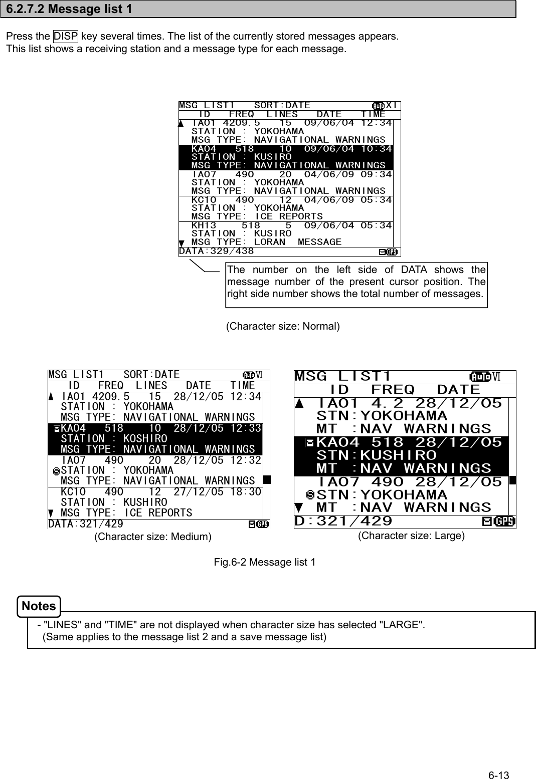
![6-14 a. Select a message Screen scrolling 1 The ‘ ‘ (‘ ‘) mark is displayed when the message list 1 scroll downward (upward) is available. 1) To meve the cursor up/down to the next line, press the ▲ ▼ key. (Cursor scrolls one by one in the message list 1.) 2) To scroll the next page of the message List 1 downward (upward) when cursor is on the bottom (top) line, press the ▼ (▲) key. 3) To read a message text, move the cursor to the message and press the ENT key. Screen scrolling 2 To skip to the next / previous message text screen is available. 1) To display to the previous / next screen, press the key. Selecting "[PGUP]"or "[PGDN]" of the sub screen can also scroll the message list 1 screen similarly to the above procedures. To display the sub screen, press the * key. - [PGDN]: Previous screen - [PGUP]: Next screen MSG LIST1 SORT:DATE XI ID FREQ LINES DATE TIME IA01 4209.5 15 09/06/04 12:34 STATION : YOKOHAMA MSG TYPE: NAVIGATIONAL WARNINGS KA04 518 10 09/06/04 10:34 STATION : KUSIRO MSG TYPE: NAVIGATIONAL WARNINGS IA07 490 20 04/06/09 09:34 STATION : YOKOHAMA MSG TYPE: NAVIGATIONAL WARNINGS KC10 490 12 04/06/09 05:34 STATION : YOKOHAMA MSG TYPE: ICE REPORTS KH13 518 5 09/06/04 05:34 STATION : KUSIRO MSG TYPE: LORAN MESSAGE DATA:329/438 Procedures Procedures Notes](https://usermanual.wiki/Japan-Radio/NCR-333/User-Guide-571910-Page-46.png)
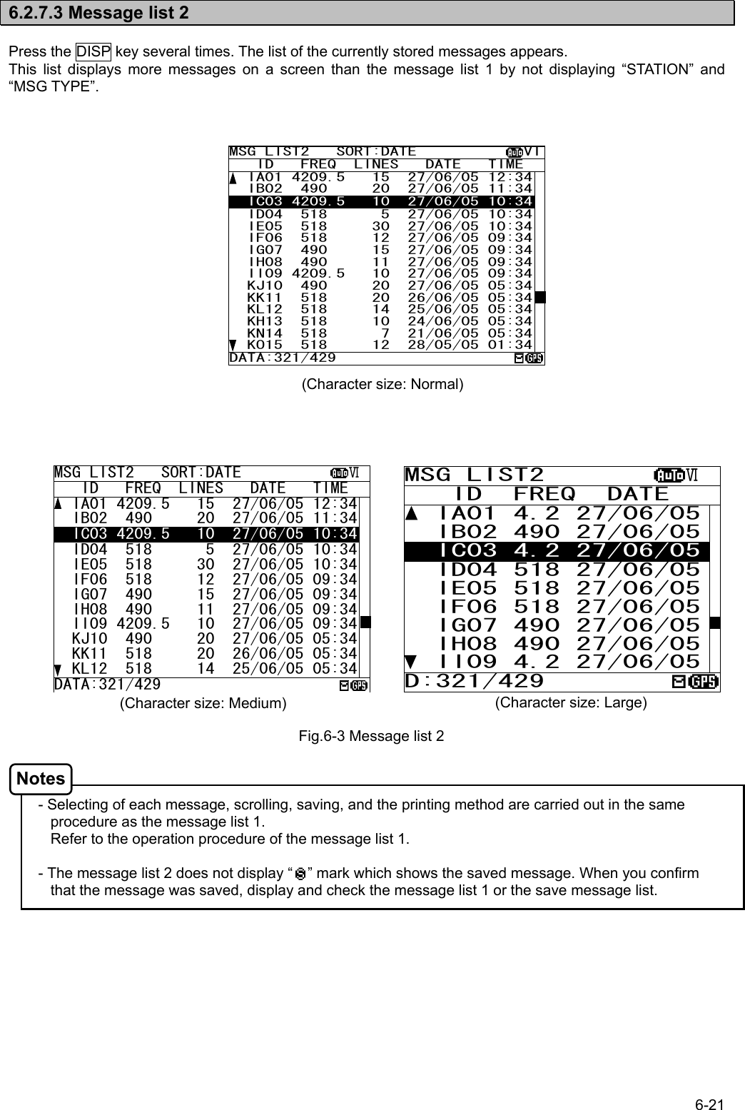
![6-15 b. Sort messages To search message quickly, messages can be sorted. 1) Press the * key. The sub screen appears. 2) Select the “LIST”, and press the ENT key. The items of “LIST” appear. 3) The items of “LIST” are as follows; SORT: The stored messages are displayed - DATE: in the order of the date received in reverse - STNS: in the order from the receiving station "A" - AREA: in the order from the NAVAREA “I” - MSGTYP: in the order from the message type “A” - UNREAD: in the order of the date received in reverse (unread messages) DISP: The messages displayed on the selected channel. - ALL: All the messages are displayed. - 518KHZ: Only 518 kHz messages are displayed. - 490KHZ: Only 490 kHz messages are displayed. - 4209.5KHZ: Only 4209.5 kHz messages are displayed. 4) Select "SORT" item, and then select “DISP” item. 5) Select the [OK], and press the ENT key. Sorting message starts. 6) After message sorting has been completed, press the ENT key or the CLR key. Rearrange the order of message conversely 1) Press the * key. The sub screen appears. 2) Select the “REVERSE”, and press the ENT key. 3) The order of the message currently displayed is rearranged conversely, and title of ‘SORT’ is highlighted. MSG LIST1 SORT:DATE XI ID FREQ LINES DATE TIME IA01 4209.5 15 09/06/04 12:34 STATION : YOKOHAMA MSG TYPE: NAVIGATIONAL WARNINGS KA04 518 10 09/06/04 10:34 STATION : KUSIRO MSG TYPE: NAVIGATIONAL WARNINGS IA07 490 20 04/06/09 09:34 STATION : YOKOHAMA MSG TYPE: NAVIGATIONAL WARNINGS KC10 490 12 04/06/09 05:34 STATION : YOKOHAMA MSG TYPE: ICE REPORTS KH13 518 5 09/06/04 05:34 STATION : KUSIRO MSG TYPE: LORAN MESSAGE DATA:329/438 *SET UP* LIST_ [REVERSE] [CHECK] SAVE MENU PRINT MENU *LIST* SORT:[DATE] STNS AREA MSGTYP UNREAD *LIST* DISP:[ALL] 518KHZ 490KHZ 4209.5KHZ [OK] [CANCEL] NOW SETTING... [OK] [CANCEL] MSG LIST1 SORT:DATE XI ID FREQ LINES DATE TIME IB21 4209.5 15 12/05/05 11:10 STATION : YOKOHAMA MSG TYPE: NAVIGATIONAL WARNINGS IA33 518 10 13/05/05 22:34 STATION : KUSIRO MSG TYPE: NAVIGATIONAL WARNINGS KA67 490 20 04/06/09 02:15 STATION : YOKOHAMA MSG TYPE: NAVIGATIONAL WARNINGS PC01 490 12 04/06/09 10:25 STATION : YOKOHAMA MSG TYPE: ICE REPORTS IA01 4209.5 15 09/06/04 12:34 STATION : KUSIRO MSG TYPE: LORAN MESSAGE DATA:329/438 *SET UP* LIST [REVERSE] [CHECK] SAVE MENU PRINT MENU Highlight a titleProcedures Procedures](https://usermanual.wiki/Japan-Radio/NCR-333/User-Guide-571910-Page-47.png)
![6-16 c. Put a check mark (Save/print/output more than one message at the same time) Each checked message can be saved (printed or output) at the same time. 1) Press the * key. The sub screen appears. 2) Select the “[CHECK]”, and press the ENT key. The sub screen is closed, and the message list 1 changes to the check screen. The check screen highlights the "CHECK" on the display title. The number of check marks is displayed on the status line. 3) Select the message for checking, and press the ENT key. The “ “ is displayed on a line with cursor. This mark means having checked the message. 4) Press the ENT key and put a check to other messages. In addition, when the following characters are displayed, It means that the checked number exceeded the number which can be saved in the memory. RX1--OV: The message of RX1 (518kHz) cannot be saved any more to the memory. RX2--OV: RX2 (490 kHz) RX3--OV: RX3 (4209.5 kHz) RX12-OV: RX1 and RX2 RX13-OV: RX1 and RX3 RX23-OV: RX2 and RX3 RX123OV: RX1, RX2 and RX3 In this case, messages still can be put a check, however, the messages cannot be printed or data can not be output. 5) Press the * key, to display the sub screen. Select "SAVE MENU", "PRINT MENU", or "PORT MENU" in the auxiliary screen. To save, print or output messages at the same time, refer to the procedure of d), e) and f). If the CLR key is pressed on the sub screen, “EXIT WITHOUT SETTING” is displayed in the sub screen. If "O.K." is selected, the check marks are removed and the display screen returns to the message list 1 screen. KH13 518 5 09/06/04 05:34 CHECKING - PRESS [ENT] KEY FINISHED - PRESS [*] KEY DATA:329/438 RX1--OV MSG LIST1 SORT:DATE XI ID FREQ LINES DATE TIME IA01 4209.5 15 09/06/04 12:34 STATION : YOKOHAMA MSG TYPE: NAVIGATIONAL WARNINGS KA04 518 10 09/06/04 10:34 STATION : KUSIRO MSG TYPE: NAVIGATIONAL WARNINGS IA07 490 20 04/06/09 09:34 STATION : YOKOHAMA MSG TYPE: NAVIGATIONAL WARNINGS KC10 490 12 04/06/09 05:34 STATION : YOKOHAMA MSG TYPE: ICE REPORTS KH13 518 5 09/06/04 05:34 STATION : KUSIRO MSG TYPE: LORAN MESSAGE DATA:329/438 *SET UP* LIST_ [REVERSE] [CHECK] SAVE MENU PRINT MENU CHECK SORT:DATE XI ID FREQ LINES DATE TIME IA01 4209.5 15 09/06/04 12:34 STATION : YOKOHAMA MSG TYPE: NAVIGATIONAL WARNINGS KA04 518 10 09/06/04 10:34 STATION : KUSIRO MSG TYPE: NAVIGATIONAL WARNINGS IA07 490 20 04/06/09 09:34 STATION : YOKOHAMA MSG TYPE: NAVIGATIONAL WARNINGS KC10 490 12 04/06/09 05:34 STATION : YOKOHAMA MSG TYPE: ICE REPORTS KH13 518 5 09/06/04 05:34 CHECKING - PRESS [ENT] KEY FINISHED - PRESS [*] KEY DATA:329/438 0 CHECK SORT:DATE XI ID FREQ LINES DATE TIME IA01 4209.5 15 09/06/04 12:34 STATION : YOKOHAMA MSG TYPE: NAVIGATIONAL WARNINGS KA04 518 10 09/06/04 10:34 STATION : KUSIRO MSG TYPE: NAVIGATIONAL WARNINGS IA07 490 20 04/06/09 09:34 STATION : YOKOHAMA MSG TYPE: NAVIGATIONAL WARNINGS KC10 490 12 04/06/09 05:34 STATION : YOKOHAMA MSG TYPE: ICE REPORTS KH13 518 5 09/06/04 05:34 CHECKING - PRESS [ENT] KEY FINISHED - PRESS [*] KEY DATA:329/438 1 CHECK SORT:DATE XI ID FREQ LINES DATE TIME IA01 4209.5 15 09/06/04 12:34 STATION : YOKOHAMA MSG TYPE: NAVIGATIONAL WARNINGS KA04 518 10 09/06/04 10:34 STATION : KUSIRO MSG TYPE: NAVIGATIONAL WARNINGS IA07 490 20 04/06/09 09:34 STATION : YOKOHAMA MSG TYPE: NAVIGATIONAL WARNINGS KC10 490 12 04/06/09 05:34 STATION : YOKOHAMA MSG TYPE: ICE REPORTS KH13 518 5 09/06/04 05:34 CHECKING - PRESS [ENT] KEY FINISHED - PRESS [*] KEY DATA:329/438 3 *SET UP* LIST [REVERSE] [CHECK] SAVE MENU PRINT MENU Number of check marksCheck screen *SET UP* EXIT WITHOUT SETTING. ARE YOU SURE? [OK] [CANCEL] Procedures](https://usermanual.wiki/Japan-Radio/NCR-333/User-Guide-571910-Page-48.png)
![6-17 d. Save messages Save one message The selected message can be saved. 1) Move cursor to the message to save. 2) Press the * key. The sub screen appears. 3) Select the “SAVE MENU”, and press the ENT key. 4) Select the “[SELECT MSG]” in the sub screen of “SAVE MANU”. - Select an item in the same procedure as “d. Save the message - 3)” (p.6-10) after the above procedure. 5) The “ “ mark on the saved message line shows the message has saved completly. Save messages at the same time The messages which put the check mark can be saved at the same time. 1) Continued from Procedure 5) of "c. Put a check mark". 2) Select the “SAVE MENU”, and the ENT key. 3) Select the “[CHECK MSG]”, and the ENT key. To clear to all check marks, select “[RESET CHECK]” and press the ENT key. - Select an item in the same procedure as “d. Save the message - 3)” (p.6-10) after the above procedure. 4) The “ “ mark on the saved message line shows the message has saved completly. MSG LIST1 SORT:DATE XI ID FREQ LINES DATE TIME IA01 4209.5 15 09/06/04 12:34 STATION : YOKOHAMA MSG TYPE: NAVIGATIONAL WARNINGS KA04 518 10 09/06/04 10:34 STATION : KUSIRO MSG TYPE: NAVIGATIONAL WARNINGS IA07 490 20 04/06/09 09:34 STATION : YOKOHAMA MSG TYPE: NAVIGATIONAL WARNINGS KC10 490 12 04/06/09 05:34 STATION : YOKOHAMA MSG TYPE: ICE REPORTS KH13 518 5 09/06/04 05:34 STATION : KUSIRO MSG TYPE: LORAN MESSAGE DATA:329/438 *SET UP* LIST_ [REVERSE] [CHECK] SAVE MENU PRINT MENU *SAVE MENU* [SELECT MSG] [CHECK MSG] [RESET CHECK] [CANCEL] To display to previous screen, select “[CANCEL]”. CHECK SORT:DATE XI ID FREQ LINES DATE TIME IA01 4209.5 15 09/06/04 12:34 STATION : YOKOHAMA MSG TYPE: NAVIGATIONAL WARNINGS KA04 518 10 09/06/04 10:34 STATION : KUSIRO MSG TYPE: NAVIGATIONAL WARNINGS IA07 490 20 04/06/09 09:34 STATION : YOKOHAMA MSG TYPE: NAVIGATIONAL WARNINGS KC10 490 12 04/06/09 05:34 STATION : YOKOHAMA MSG TYPE: ICE REPORTS KH13 518 5 09/06/04 05:34 CHECKING - PRESS [ENT] KEY FINISHED - PRESS [*] KEY DATA:329/438 3 *SET UP* LIST [REVERSE] [CHECK] SAVE MENU PRINT MENU MSG LIST1 SORT:DATE XI ID FREQ LINES DATE TIME IA01 4209.5 15 09/06/04 12:34 STATION : YOKOHAMA MSG TYPE: NAVIGATIONAL WARNINGS KA04 518 10 09/06/04 10:34 STATION : KUSIRO MSG TYPE: NAVIGATIONAL WARNINGS IA07 490 20 04/06/09 09:34 STATION : YOKOHAMA MSG TYPE: NAVIGATIONAL WARNINGS KC10 490 12 04/06/09 05:34 STATION : YOKOHAMA MSG TYPE: ICE REPORTS KH13 518 5 09/06/04 05:34 STATION : KUSIRO MSG TYPE: LORAN MESSAGE DATA:329/438 Procedures Notes Procedures Notes *SAVE MENU* [SELECT MSG] [CHECK MSG] [RESET CHECK] [CANCEL]](https://usermanual.wiki/Japan-Radio/NCR-333/User-Guide-571910-Page-49.png)
![6-18 e. Print messages or the information on equipment Print one message The selected message can be printed. 1) Move cursor onto the message to print. 2) Press the * key. The sub screen appears. 3) Select the “PRINT MENU”, and the ENT key. 4) Select the “[SELECT MSG]” in the sub screen of “PRINT MENU”. - Select an item in the same procedure as “e. Print the message - 3)” (p.6-11) after the above procedure. Print messages at the same time The messages which put the check mark can be printed at the same time. 1) Continued from Procedure 5) of "c. Put a check mark". (The sub screen is displayed.) 2) Select the “PRINT MENU”, and the ENT key. 3) Select the “[CHECK MSG]”, and the ENT key. To clear to all check marks, select “[RESET CHECK]” and press the ENT key. - Select an item in the same procedure as “e. Print the message - 3)” (p.6-11) after the above procedure. MSG LIST1 SORT:DATE XI ID FREQ LINES DATE TIME IA01 4209.5 15 09/06/04 12:34 STATION : YOKOHAMA MSG TYPE: NAVIGATIONAL WARNINGS KA04 518 10 09/06/04 10:34 STATION : KUSIRO MSG TYPE: NAVIGATIONAL WARNINGS IA07 490 20 04/06/09 09:34 STATION : YOKOHAMA MSG TYPE: NAVIGATIONAL WARNINGS KC10 490 12 04/06/09 05:34 STATION : YOKOHAMA MSG TYPE: ICE REPORTS KH13 518 5 09/06/04 05:34 STATION : KUSIRO MSG TYPE: LORAN MESSAGE DATA:329/438 *SET UP* LIST_ [REVERSE] [CHECK] SAVE MENU PRINT MENU *PRINT MENU* [SELECT MSG] [CHECK MSG] [LIST] [STATUS] BATCH PRINT CHECK SORT:DATE XI ID FREQ LINES DATE TIME IA01 4209.5 15 09/06/04 12:34 STATION : YOKOHAMA MSG TYPE: NAVIGATIONAL WARNINGS KA04 518 10 09/06/04 10:34 STATION : KUSIRO MSG TYPE: NAVIGATIONAL WARNINGS IA07 490 20 04/06/09 09:34 STATION : YOKOHAMA MSG TYPE: NAVIGATIONAL WARNINGS KC10 490 12 04/06/09 05:34 STATION : YOKOHAMA MSG TYPE: ICE REPORTS KH13 518 5 09/06/04 05:34 CHECKING - PRESS [ENT] KEY FINISHED - PRESS [*] KEY DATA:329/438 3 *SET UP* LIST [REVERSE] [CHECK] SAVE MENU PRINT MENU *PRINT MENU* [SELECT MSG] [CHECK MSG] [LIST] [STATUS] BATCH PRINT *PRINT MENU [LIST] [STATUS] BATCH PRINT [RESET CHECK] [CANCEL] To display to previous screen, select “[CANCEL]”. Procedures Procedures Notes Notes](https://usermanual.wiki/Japan-Radio/NCR-333/User-Guide-571910-Page-50.png)
![6-19 *PRINT MENU* [SELECT MSG] [CHECK MSG] [LIST] [STATUS] BATCH PRINT *BATCH PRINT MENU* [ALL STORED MSG] [ALL SAVE MSG] *BATCH PRINT MENU* -- SELECT MSG -- CHANNEL:4209.5 STATION:A MSG TYP:L Print the information on equipment The list of stored messages and the setting status can be printed. 1) Press the * key. The sub screen appears. 2) Select the “[LIST]” or “[STATUS]”, and press the ENT key. [LIST]: The list of stored messages is printed. [STATUS]: The setting status is printed. The contents of "6.3.5.3 Setting status of the NAVTEX receiver" are printed. 3) Printing starts. After printing is completed, close the sub screen. Print messages at the same time The stored messages can be printed at the same time according to type, station and channel. 1) Press the * key. The sub screen appears. 2) Select the “BATCH PRINT”, and press the ENT key. The sub screen of “BATCH PRINT MENU” appears. 3) Select the following message type for printing. The "SELECT MSG" can select the message printing by the receiving channel, receiving station, message type. [ALL STORED MSG]: All stored messages are printed. [ALL SAVE MSG]: All saved messages are printed. SELECT MSG: The messages of the conditions selected from the following three items are printed. - CHANNEL: The receiving channel is selected from ‘518kHz’, ‘490kHz’, ‘4209.5kHz’ or ‘ALL’. - STATION: The receiving station is selected from 'A' to 'Z', or 'ALL'. - MSG TYP: The message type is selected from ‘A' to 'Z', or 'ALL'. 4) To start printing, select item and press the ENT key. “ARE YOU SURE?” is displayed on the sub screen, if the ENT key is pressed after selecting “[ALL STORED MSG]” or “[ALL SAVE MSG]”. When in “SELECT MSG”, “ARE YOU SURE?” is displayed on the sub screen, if the ENT key is pressed after selecting “MSG TYP”. - Select an item in the same procedure as “e. Print the message - 3)” (p.6-10) after the above procedure. *PRINT MENU* [SELECT MSG] [CHECK MSG] [LIST] [STATUS] BATCH PRINT Procedures Procedures Notes](https://usermanual.wiki/Japan-Radio/NCR-333/User-Guide-571910-Page-51.png)
![6-20 f. Output messages from an external port Output one message The external serial port output the selected message’s data. 1) Move cursor to the message to output. 2) Press the * key. The sub screen appears. 3) Select the “PORT MENU”, and the ENT key. 4) Select the “[SEL-DATA OUT]” or “[SEL-DISP OUT]” in the sub screen of “PORT MENU”. - Select an item in the same procedure as “f. Output the message from an external port - 3)” (p.6-12) after the above rocedure. Output messages at the same time The messages with the check mark can be output at the same time. 1) Continued from Procedure 5) of "c. Put a check mark". (The sub screen is displayed.) 2) Select the “PORT MENU”, and the ENT key. 3) Select the “[CHK-DATA OUT]” or “CHK-DISP OUT”, and the ENT key. To clear to all check marks, select “[RESET CHECK]” and press the ENT key. - CHK-DATA OUT: Message data outgoing from ECDIS or INS port. - CHK-DISP OUT: Message data outgoing from DISP port. - Select an item in the same procedure as “f. Output the message from an external port - 3)” (p.6-12) after the above rocedure. MSG LIST1 SORT:DATE XI ID FREQ LINES DATE TIME IA01 4209.5 15 09/06/04 12:34 STATION : YOKOHAMA MSG TYPE: NAVIGATIONAL WARNINGS KA04 518 10 09/06/04 10:34 STATION : KUSIRO MSG TYPE: NAVIGATIONAL WARNINGS IA07 490 20 04/06/09 09:34 STATION : YOKOHAMA MSG TYPE: NAVIGATIONAL WARNINGS KC10 490 12 04/06/09 05:34 STATION : YOKOHAMA MSG TYPE: ICE REPORTS KH13 518 5 09/06/04 05:34 STATION : KUSIRO MSG TYPE: LORAN MESSAGE DATA:329/438 *SET UP* [REVERSE] [CHECK] SAVE MENU PRINT MENU PORT MENU *PORT MENU* [SEL-DATA OUT] [SEL-DISP OUT] [CHK-DATA OUT] [CHK-DISP OUT] [RESET CHECK] CHECK SORT:DATE XI ID FREQ LINES DATE TIME IA01 4209.5 15 09/06/04 12:34 STATION : YOKOHAMA MSG TYPE: NAVIGATIONAL WARNINGS KA04 518 10 09/06/04 10:34 STATION : KUSIRO MSG TYPE: NAVIGATIONAL WARNINGS IA07 490 20 04/06/09 09:34 STATION : YOKOHAMA MSG TYPE: NAVIGATIONAL WARNINGS KC10 490 12 04/06/09 05:34 STATION : YOKOHAMA MSG TYPE: ICE REPORTS KH13 518 5 09/06/04 05:34 CHECKING - PRESS [ENT] KEY FINISHED - PRESS [*] KEY DATA:329/438 3 *PORT MENU* [SEL-DATA OUT] [SEL-DISP OUT] [CHK-DATA OUT] [CHK-DISP OUT] [RESET CHECK] *SET UP* [REVERSE] [CHECK] SAVE MENU PRINT MENU PORT MENU Procedures Procedures Notes Notes](https://usermanual.wiki/Japan-Radio/NCR-333/User-Guide-571910-Page-52.png)
![6-23 a. Delete the saved message If the message is deleted from the save message list, “ ” mark displayed on the message list 1 will also be deleted. The message is deleted after stored for 70 hours, and the message is deleted from the message list 1 and 2. Delete one message The selected message can be deleted. 1) Move cursor onto the message to delete. 2) Press the * key. The sub screen appears. 3) Select the “DELETE MENU”, and press the ENT key. 4) Select the “[SELECT MSG]” in the sub screen of “DELETE MANU”. 5) After message deleting has been completed, the selected message is deleted from the save message list and the “ “ mark is deleted from the message list 1. In addition, the message is deleted after stored for 70 hours, and the message is deleted from the message list 1 and 2. Delete messages at the same time The messages which put the check mark can be deleted at the same time. 1) Put check marks in the same procedure as "c.Put a check mark" of "6.2.6.2 Message list 1." 2) Press the * key. The sub screen appears. 3) Select the “DELETE MENU”, and press the ENT key. 5) Select the “[CHECK MSG]”, and the ENT key. 4) If the ENT key is pressed after selecting “[RESET CHECK]”, all check marks are cleared. 5) After message deleting has been completed, the selected message has deleted from the save message list and the “ “ mark is deleted from the message list 1. The message is deleted after stored for 70 hours, and the message is deleted from the message list 1 and 2. SAVE MSG SORT:DATE XI ID FREQ LINES DATE TIME IA01 4209.5 15 09/06/04 12:34 STATION : YOKOHAMA MSG TYPE: NAVIGATIONAL WARNINGS KA04 518 10 09/06/04 10:34 STATION : KUSIRO MSG TYPE: NAVIGATIONAL WARNINGS IA07 490 20 04/06/09 09:34 STATION : YOKOHAMA MSG TYPE: NAVIGATIONAL WARNINGS KC10 490 12 04/06/09 05:34 STATION : YOKOHAMA MSG TYPE: ICE REPORTS KH13 518 5 09/06/04 05:34 STATION : KUSIRO MSG TYPE: LORAN MESSAGE DATA: 21438 *SET UP* LIST_ [REVERSE] [CHECK] DELETE MENU PRINT MENU *DELETE MENU* [SELECT MSG] [CHECK MSG] [RESET CHECK] [CANCEL] To display to previous screen, select “[CANCEL]”. CHECK SORT:DATE XI ID FREQ LINES DATE TIME IA01 4209.5 15 09/06/04 12:34 STATION : YOKOHAMA MSG TYPE: NAVIGATIONAL WARNINGS KA04 518 10 09/06/04 10:34 STATION : KUSIRO MSG TYPE: NAVIGATIONAL WARNINGS IA07 490 20 04/06/09 09:34 STATION : YOKOHAMA MSG TYPE: NAVIGATIONAL WARNINGS KC10 490 12 04/06/09 05:34 STATION : YOKOHAMA MSG TYPE: ICE REPORTS KH13 518 5 09/06/04 05:34 CHECKING - PRESS [ENT] KEY FINISHED - PRESS [*] KEY DATA: 21/ 37 *SET UP* LIST [REVERSE] [CHECK] DELETE MENU PRINT MENU SAVE MSG SORT:DATE XI ID FREQ LINES DATE TIME KC10 490 12 09/06/05 05:34 STATION : YOKOHAMA MSG TYPE: ICE REPORTS KH13 518 5 09/06/05 05:34 STATION : KUSIRO MSG TYPE: LORAN MESSAGE IA11 518 10 08/06/05 22:20 STATION : YOKOHAMA MSG TYPE: NAVIGATIONAL WARNINGSIA13 518 14 08/06/05 18:20 STATION : YOKOHAMA MSG TYPE: NAVIGATIONAL WARNINGS IA42 518 28 07/06/05 22:21 STATION : YOKOHAMA MSG TYPE: NAVIGATIONAL WARNINGSDATA: 18/ 34 Caution Procedures Procedures](https://usermanual.wiki/Japan-Radio/NCR-333/User-Guide-571910-Page-55.png)
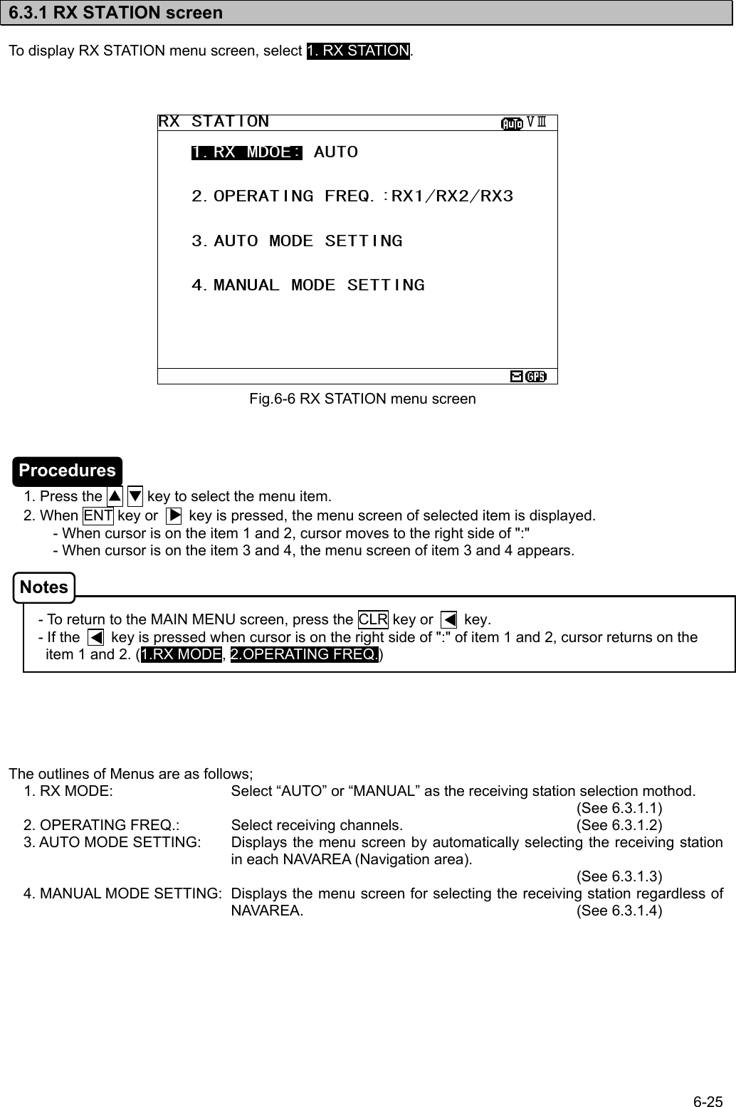
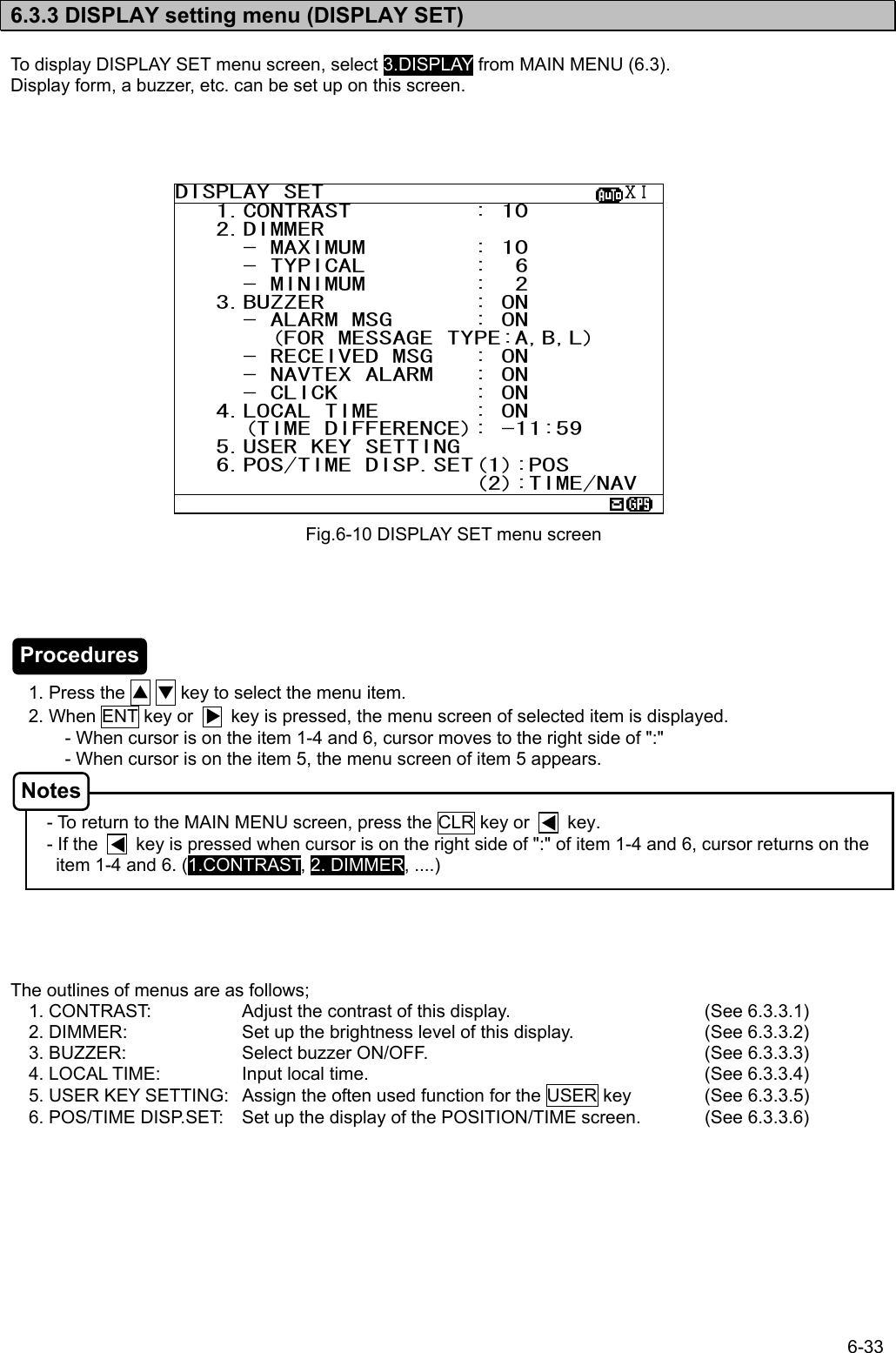
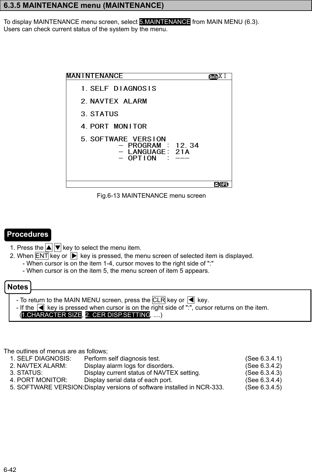
![6-24 6.3 MAIN MEMU Main menu displays menu items for setting, and maintenance, etc. To display the Main menu, press the MENU key during operation. 1. Press the ▲ ▼ key to select the menu item. 2. When the ENT key or the key is pressed, the menu screen of selected item is displayed. Previous screen is displayed when the CLR key is pressed. (Such as message text display or message list 1, etc). The outlines of menus are as follows; 1. RX STATION: Displays the menu for selecting receiving stations (See 6.3.1) 2. MESSAGE TYPE: Displays the menu for selecting message types (See 6.3.2) 3. DISPLAY: Displays the menu for setting the display unit. (See 6.3.3) 4. NAVTEX: Displays the menu for setting the NAVTEX receiver. (See 6.3.4) 5. MAINTENANCE: Displays the maintenance menu. (See 6.3.5) 6. LANGUAGE: Selects the menu display language. (See 6.3.6) [EXIT]: Return to the previous screen (Such as message text display or message list 1, etc.) Fig.6-5 Main menu MAIN MENU ⅤⅢ 1.RX STATION_ 2.MESSAGE TYPE 3.DISPLAY 4.NAVTEX 5.MAINTENANCE 6.LANGUAGE: ENGLISH [EXIT] Procedures Notes](https://usermanual.wiki/Japan-Radio/NCR-333/User-Guide-571910-Page-56.png)
![6-29 b. Cancel settings When the CLR/ MENU/ DISP/ USER key is pressed while setting up “a. Select receiving stations”, the information screen (the sub screen) as shown in the following figure is displayed. Select “OK” or “CANCEL”. OK: Canceling the receiving station settings, the screen changes according to the pressed key. CANCEL: The information screen is closed. Continu the receiving station settings. c. Set up the next channel (or NAVAREA) After a setup of a channel (or NAVAREA) finishes, the next channel (or NAVAREA) can be set up continuously. 1) Press the ▲ ▼ key for selecting FREQUENCY (or NAVAREA), and press the ENT key. Cursor moves to the right side of ":" 2) Press the ▲ ▼ key and select the number of NAVAREA. And then, press the ENT key. 3) Select a receiving station in the same procedures as “a. Select receiving stations”. STATION(AUTO) ⅩⅠNAVAREA :ⅩⅠ FREQUENCY:RX1(518K) SELECT ALL A:JAYAPURA N:GUANGZHOU B:AMBON O:FUZHOU C:SINGAPORE P:MEILUNG D:MAKASSAR Q:SHANGHAI E:JAKARTA R:DALIAN F:BANGKOK RADIO S:SANDAKAN G:NAHA T:MIRI H:MOJI U:PENANG I:YOKOHAMA V:CHUKPYON/GUAM J:OTARU W:PYONSAN K:KUSHIRO/DANANG X:HO CHI MINH L:HONG KONG Y: M:SANYA Z: *STNS(AUTO) SET* EXIT WITHOUT SAVING. ARE YOU SURE? (SAVE:PRESS’’*’’KEY) [OK] [CANCEL]Procedures](https://usermanual.wiki/Japan-Radio/NCR-333/User-Guide-571910-Page-61.png)
![6-30 d. Save (or Clear) settings Save (or clear) the settings on the sub screen after setting up. 1) Press the * key. The sub screen appears. Cursor is on the [CLEAR]. 2) Press the ▼ key and select the following items. 3) Save settings Select the [OK], and press the ENT key. Clear only settings of the screen that is currently open Select the [CLEAR], and press the ENT key. The receiving station settings of the screen that is currently open are restored to its former state, and the cursor returns to NAVAREA. Clear all settings Select the [ALL CLEAR], and press the ENT key. All the receiving station settings are restored to its former state, and the cursor returns to NAVAREA. Continue setting up Select the [CANCEL], and press the ENT key. This sub screen is closed. 4) To start save precess, select [OK]. Then, “SAVE OK” is displayed on the sub screen. Press the ENT or CLR key. RX STATION menu screen appears. STATION(AUTO) ⅩⅠNAVAREA :ⅩⅠ FREQUENCY:RX1(518K) SELECT ALL A:JAYAPURA N:GUANGZHOU B:AMBON O:FUZHOU C:SINGAPORE P:MEILUNG D:MAKASSAR Q:SHANGHAI E:JAKARTA R:DALIAN F:BANGKOK RADIO S:SANDAKAN G:NAHA T:MIRI H:MOJI U:PENANG I:YOKOHAMA V:CHUKPYON/GUAM J:OTARU W:PYONSAN K:KUSHIRO/DANANG X:HO CHI MINH L:HONG KONG Y: M:SANYA Z: *STNS(AUTO) SET* SAVE CHANGES TO THIS SETTING? [CLEAR] [ALL CLEAR] [OK] [CANCEL] *STNS(AUTO) SET* NOW SAVING... [OK] [CANCEL] *STNS(AUTO) SET* SAVE OK [OK] [CANCEL] *STNS(AUTO) SET* SAVE CHANGES TO THIS SETTING? [CLEAR] [ALL CLEAR] [OK] [CANCEL] ENT Saving is completed Procedures](https://usermanual.wiki/Japan-Radio/NCR-333/User-Guide-571910-Page-62.png)
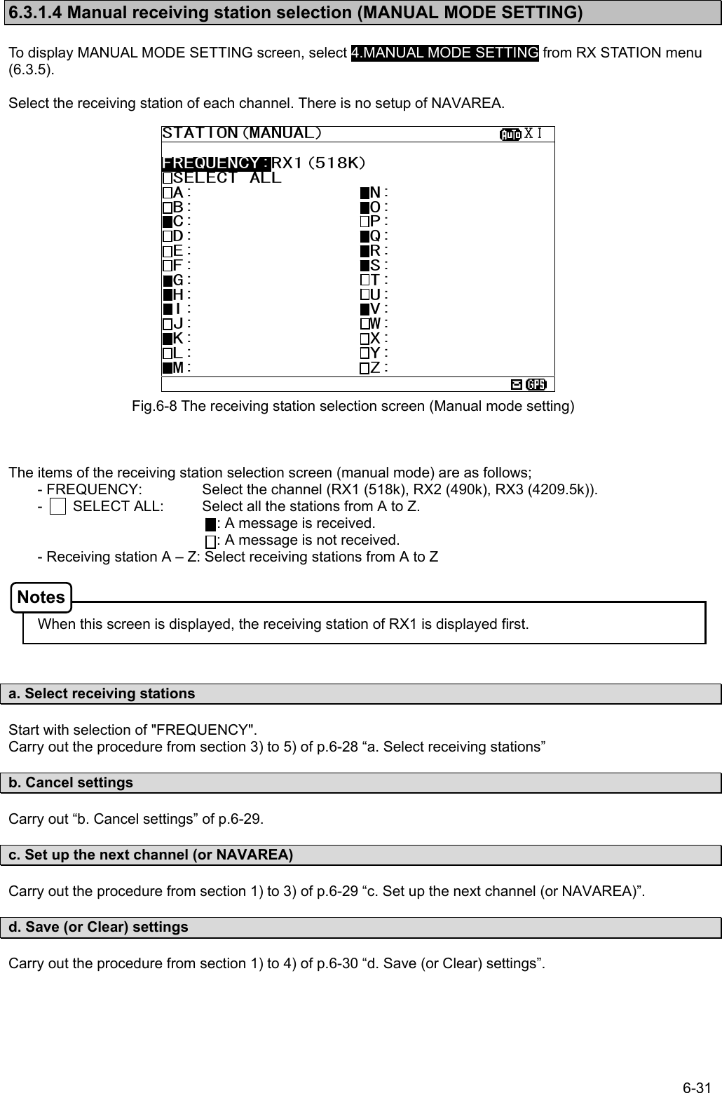
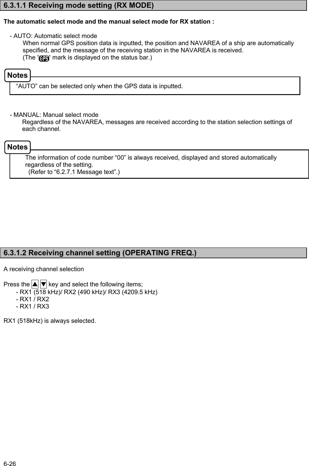
![6-32 6.3.2 Receiving message type settings (MESSAGE TYPE SETTING) To display MESSAGE TYPE SETTING menu screen, select 2. MESSAGE TYPE SETTING. The items of the receiving message type selection screen are as follows; - FREQUENCY: Select the channel (RX1 (518k), RX2 (490k), RX3 (4209.5k)). - SELECT ALL: Select all the messages from A to Z. : A message is received. : A message is not received. - Receiving message A – Z : Select receiving message from A to Z Navigational warning [A], Meteorological warning [B], Search and rescue information/piracy and armed robbery [D], Navigational warning (additional) [L] are obliged to receive a message. These message types setting cannot be changed. a. Select receiving message types Start with selection of "FREQUENCY". Carry out the procedure from section 3) to 5) of p.6-28 “a. Select receiving stations”. b. Cancel settings Carry out “b. Cancel settings” of p.6-29. c. Save (ro Clear) settings Carry out the procedure from section 1) to 4) of p.6-30 “d. Save (or Clear) settings”. Fig.6-9 MESSAGE TYPE menu screen MSG TYPE ⅩⅠ FREQUENCY:RX1(518K) SELECT ALL A:NAV WARNINGS N:[SPARE] B:MET WARNINGS O:[SPARE] C:ICE REPORT P:[SPARE] D:SERCH & RESCUE Q:[SPARE] E:MET FORECAST R:[SPARE] F:PILOT SERVICE S:[SPARE] G:DECCA T:[SPARE] H:LORAN U:[SPARE] I:[SPARE] V:SPECIAL J:SATNAV W:SPECIAL K:OTHER NAVAID X:SPECIAL L:NAV WARNINGS Y:SPECIAL M:[SPARE] Z:NO MESSAGES Notes](https://usermanual.wiki/Japan-Radio/NCR-333/User-Guide-571910-Page-64.png)
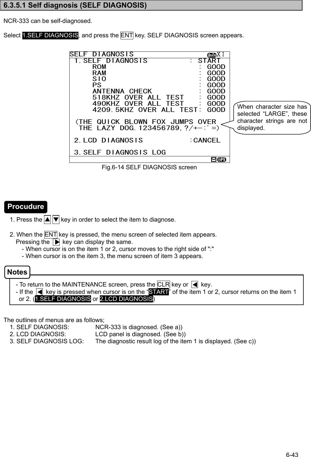
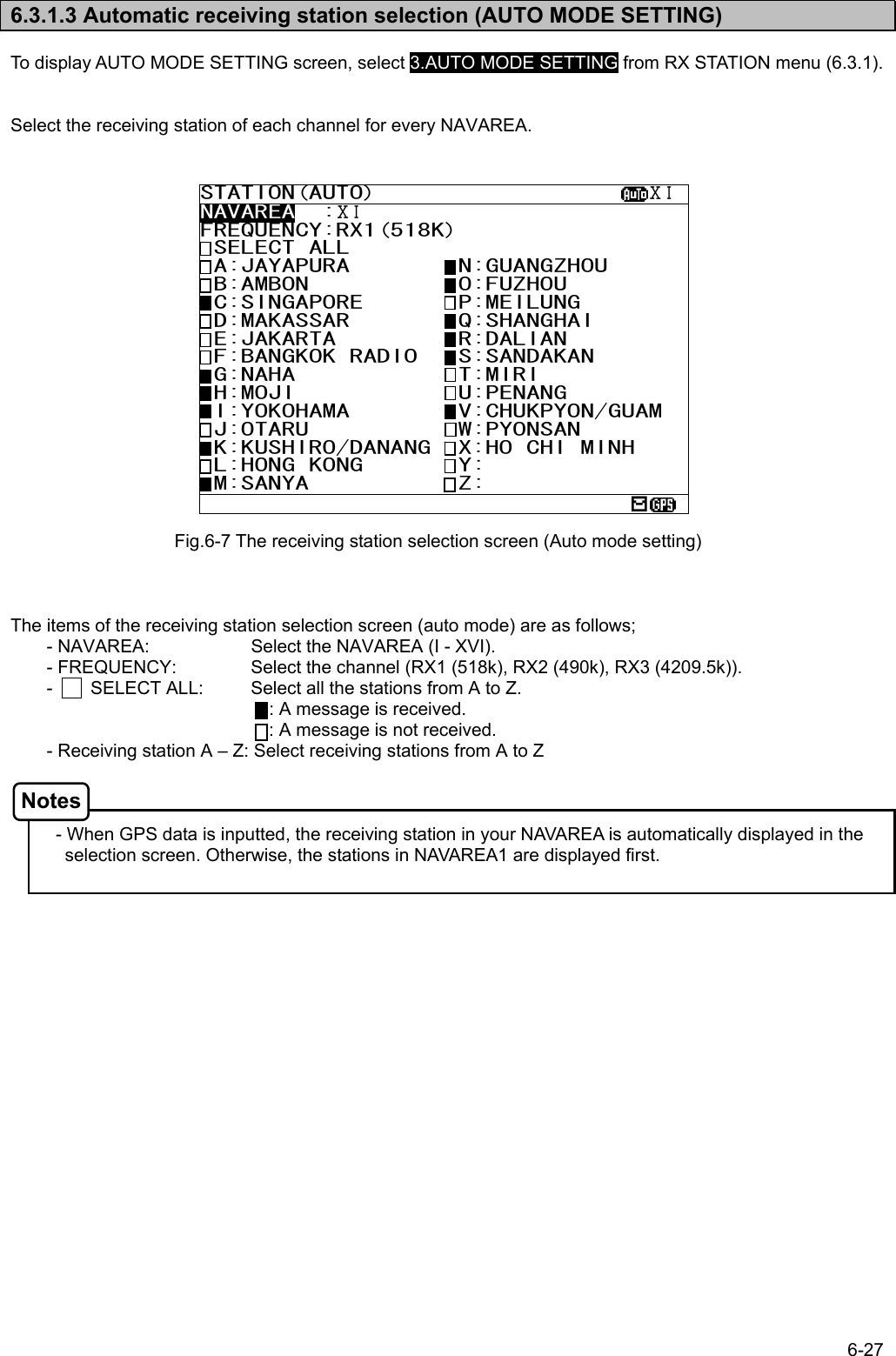
![6-44 a. The Diagnosis of equipment (SELF DIAGNOSIS) 1) Select 1.SELF DIAGNOSIS, and press the ENT key. Cursor moves to the right side of ":". 2) Press the ▲ ▼ key and select the following items; START: Self diagnosis is started. However, the diagnostic results are not printed. ST-PRTN: Self diagnosis is started. After self diagnosis is completed, the diagnosis results are printed. CANCEL: Self diagnosis is not started. Cursor returns to 1.SELF DIAGNOSIS. 3) Select the “START” or “ST-PRTN”, and then press the ENT key. Self diagnosis starts by the “ROM” test and is ended by the “4209.5 kHz over all test”. During diagnosis, “SELF DIAGNOSIS” of screen title repeats blink. The buzzer sounds at the last of diagnosis, and check that the buzzer sounds normally. Press CLR key to stop the beeping. “OVER ALL TEST” takes about 15 seconds per test. Whenever one test (OVER ALL TEST) is completed, character string as shown in the following figure is displayed. When “*“ is displayed in a character string, the test result is NG. When the result of the malfunction is displayed, contact our service center or an agency as soon as possible after referring to troubleshooting of Chapter 7. The list of diagnosis items Diagnosis items Explanation Corrective Action ROM The data memory and the program memory are checked. When the program memory is abnormal (NG), ‘[1]’ is displayed, and when the data memory is abnormal, ‘[2]’ is displayed. RAM The memory for temporarily storage is checked. SIO Serial interfaces are checked. When the ‘ECDIS/GPS’ port is abnormal (NG), ‘[1]’ is displayed, and when the ‘Maintenance/Printer’ port is abnormal, ‘[2]’ is displayed, and when the ‘DISP’ port is abnormal, ‘[3]’ is displayed. PS The power supply part is checked. Replace CMJ-501N. ANTENNA CHECK Connection with NAVTEX antenna is checked. 518KHZ OVER ALL TEST Internal receiver (RX1) is checked. 490KHZ OVER ALL TEST Internal receiver (RX2) is checked. 4209.5KHZ OVER ALL TEST Internal receiver (RX3) is checked. Replace CMN-2333. 1.SELF DIAGNOSIS : START ROM : GOOD RAM : GOOD SIO : GOOD PS : GOOD ANTENNA CHECK : GOOD 518KHZ OVER ALL TEST: 490KHZ OVER ALL TEST: 4209.5KHZ OVER ALL TEST: 1.SELF DIAGNOSIS : START ROM : GOOD RAM : GOOD SIO : GOOD PS : GOOD ANTENNA CHECK : GOOD 518KHZ OVER ALL TEST: GOOD 490KHZ OVER ALL TEST: 4209.5KHZ OVER ALL TEST: (THE QUICK BLOWN FOX JUMPS OVER THE LAZY DOG.123456789,?/+-:’=) Procudure Caution OVER ALL TEST: "OVER ALL TEST" is the test which outputs a test signal from the inside of the circuit, and receives the signal from each receiver. Test signal (Character strings): THE QUICK BLOWN FOX JUMPS OVER THE LAZY DOG. 123456789,?/+-:’=](https://usermanual.wiki/Japan-Radio/NCR-333/User-Guide-571910-Page-76.png)
![6-45 SELF DIAGNOSIS LOG ⅩⅠ 9.RESULT 29/06/05 12:34 ROM[1][2] :NG RAM :GOOD SIO[1][2][3] :NG PS :GOOD ANTENNA CHECK :GOOD 518KHZ OVER ALL TEST:GOOD 490KHZ OVER ALL TEST:GOOD 4209.5KHZ OVER ALL TEST:GOOD b. The diagnosis of LCD panel (LCD DIAGNOSIS) 1) Select 2.LCD DIAGNOSIS, and press the ENT key. Cursor moves to the right side of ":". 2) Press the ▲ ▼ key and select the following items; START: Diagnosis is started. CANCEL: Diagnosis is canceled, and cursor returns to 2.LCD DIAGNOSIS. 3) Select the “START”, and press the ENT key. This diagnosis blinks the viewing area (White -> Black -> White-> ...). c. Self diagnosis log (SELF DIAGNOSIS LOG) 1) Select 3.SELF DIAGNOSIS LOG, and press the ENT key. SELF DIAGNOSIS LOG screen appears. The newest result is displayed on this screen. 2) To display the next old result, press the ▼ key. (Up to last 10 results) The diagnosed time is displayed when external GPS receiver is connected. ”--/--/-- --:--“ is displayed when time is not able to be acquired. (External GPS receiver is not connected.) To print a result to the external printer, press the * key in order to display the sub screen. Select the “[PRINT OUT]”, and press the ENT key. Printing is started. To stop printing, press the CLR key while printing. To return to the SELF DIAGNOSIS screen, select the “[CANCEL]” and press the ENT key. SELF DIAGNOSIS LOG ⅩⅠ 9.RESULT 29/06/05 12:34 ROM[1][2] :NG RAM :GOOD SIO[1][2][3] :NG PS :GOOD ANTENNA CHECK :GOOD 518KHZ OVER ALL TEST:GOOD 490KHZ OVER ALL TEST:GOOD 4209.5KHZ OVER ALL TEST:GOOD *DIAGNOSIS LOG* [PRINT OUT] [CANCEL] Procudure Procudure](https://usermanual.wiki/Japan-Radio/NCR-333/User-Guide-571910-Page-77.png)
![6-46 6.3.5.2 NAVTEX alarms (NAVTEX ALARM) To display NAVTEX ALARM screen, select 2.NAVTEX ALARM from MAINTENANCE menu (6.3.5). In the NAVTEX ALARM screen, the present alarm is displayed. On the ALARM HISTORY screen, the alarm which occurred in operation can be displayed from the latest one to a maximum of 20 affairs. - To return to the MAINTENANCE screen, press the CLR key or key. - "NO DATA" is displayed when NAVTEX alarm has not occurred. To print the NAVTEX alarms to the external printer, press the * key in order to display the sub screen. Select the “[PRINT OUT]”, and press the ENT key. Printing is started. To stop printing, press the CLR key while printing. To return to the NAVTEX ALARM screen, select the “[CANCEL]” and press the ENT key. Fig.6-15 NAVTEX ALARM screenNAVTEX ALARM ⅩⅠ 11/12/05 15:34 054,A,Printer err *NAVTEX ALARM* [HISTORY] [PRINT OUT] [CANCEL] NAVTEX ALARM ⅩⅠ 11/12/05 15:34 054,A,Printer err Notes](https://usermanual.wiki/Japan-Radio/NCR-333/User-Guide-571910-Page-78.png)
![6-47 a. Alarm history (ALARM HISTORY) This screen displays a history of alarms which occur while the power is on. It displays the alarm history from the most recent one maximum 20 lines. To return to the NAVTEX ALARM screen, press the CLR key or key. 1) To display the next old result, press the ▼ key. - “ “ mark is displayed on the bottom line when the alarm history screen is able to scroll downward. - “ “ mark is displayed on the top line when the alarm history screen is able to scroll upward. - Press the ▲ ▼ key and scroll the viewing area. The time of an alarm occurred and is restored is displayed when external GPS receiver is connected. ”--/--/-- --:--“ is displayed when time is not able to be acquired. (External GPS receiver is not connected.) The display of the alarm is described. Alarm message: 001, V, antenna malfufnction 1 2 3 1: The alarm number (refer to the following table) 2: The alarm condition -> “V”: Healthy status, “A”: Alarm is occurring 3: Alarm’s description text (refer to the following table) The list of NAVTEX alarm Alarm No. Alarm’s description text The contents of unusual detection 002 Receiver 1 malfunction Unusual detection at the RX1 003 Receiver 2 malfunction Unusual detection at the RX2 004 Receiver 3 malfunction Unusual detection at the RX3 005 General failure Unusual detection at the power supply part 006 Built in self test failure Self diagnosis failure 051 Antenna malfunction Unusual detection of antenna connection 052 Flash memory error The data in a memory is broken. 053 Rx unit modem error Unusual detection at the modem part 054 Printer error External printer has malfunction 055 EXT SIO output error Unusual detection at the “DISP” output port 2) To print the NAVTEX alarms to the external printer, press the * key in order to display the sub screen. Select the “[PRINT OUT]”, and press the ENT key. Printing is started. [PRINT OUT]: Printing is started. [CANCEL]: Diagnosis is canceled, and the sub screen is closed. Fig.6-16 ALARM HISTORY screen NAVTEX ALARM ⅩⅠ 3.11/12/04 15:30 001 A antenna malfunction 4.11/12/04 15:30 002 A power supply error 5.02/11/04 02:31 001 V antenna malfunction 6.02/11/04 02:19 001 A antenna malfunction 7.23/09/04 22:15 001 V antenna malfunction 8.23/09/04 22:15 002 V power supply error 9.23/09/04 22:14 002 A power supply error 10.23/09/04 22:13 001 A antenna malfunction *NAVTEX ALARM* [PRINT OUT] [CANCEL] NAVTEX ALARM ⅩⅠ 3.11/12/04 15:30 001 A antenna malfunction 4.11/12/04 15:30 002 A power supply error 5.02/11/04 02:31 001 V antenna malfunction 6.02/11/04 02:19 001 A antenna malfunction 7.23/09/04 22:15 001 V antenna malfunction 8.23/09/04 22:15 002 V power supply error 9.23/09/04 22:14 002 A power supply error 10.23/09/04 22:13 001 A antenna malfunction Procudure](https://usermanual.wiki/Japan-Radio/NCR-333/User-Guide-571910-Page-79.png)
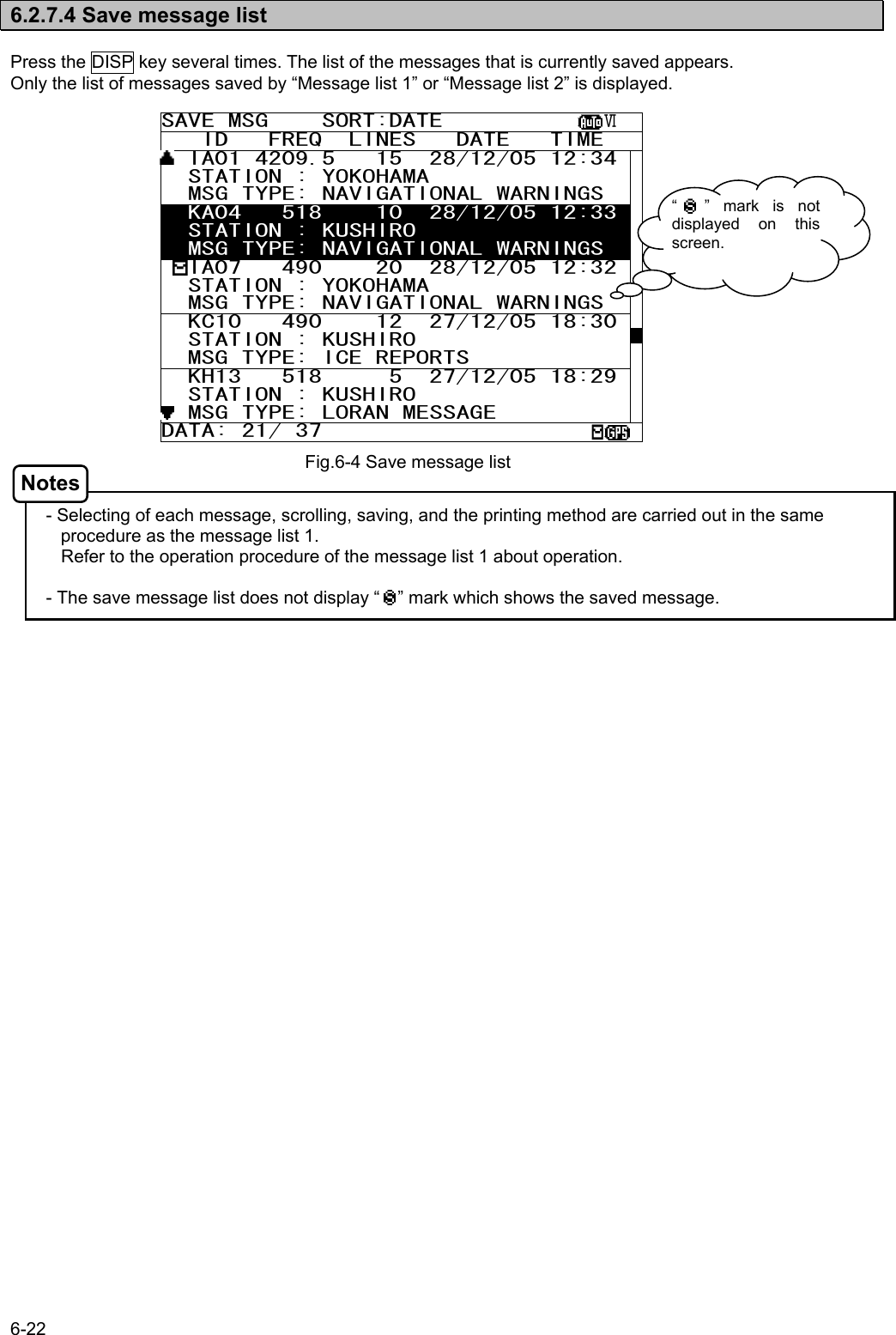
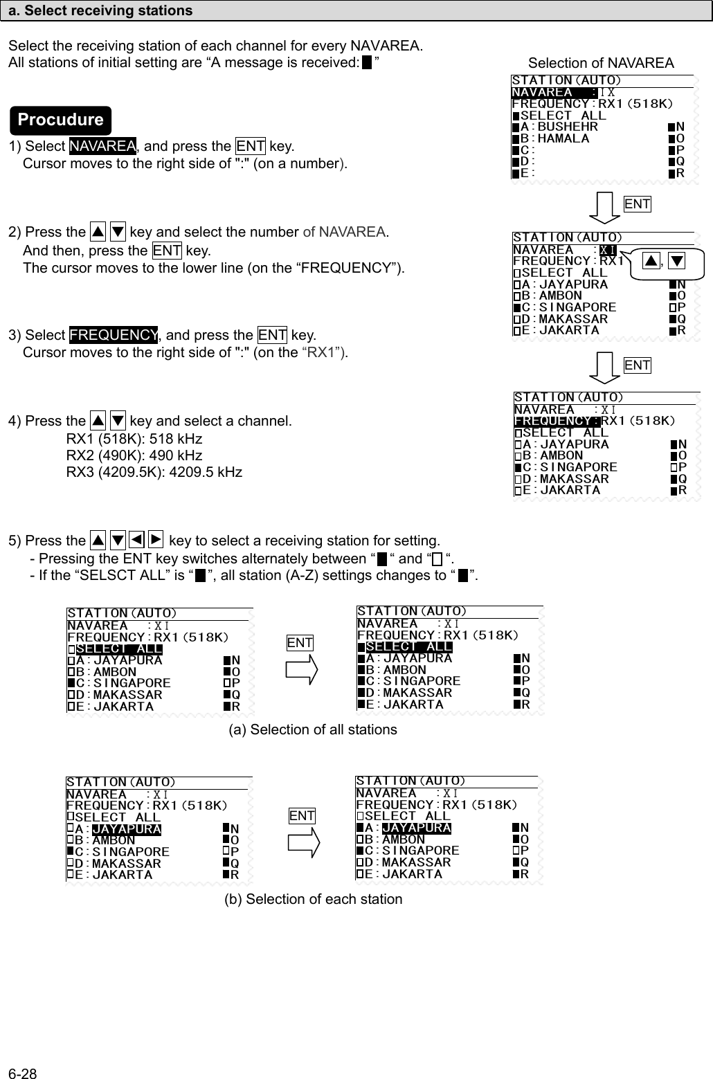
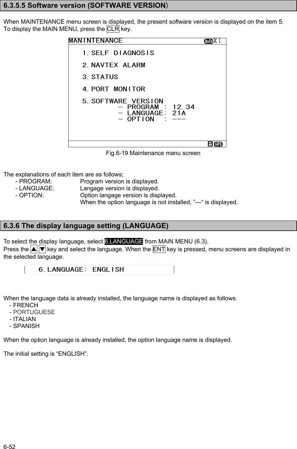
![6-48 6.3.5.3 Setting status of the NAVTEX Receiver (STATUS) To display STATUS screen, select 3.STATUS from MAINTENANCE menu (6.3.5). The setting information of NCR-333 is displayed on the screen. The setting information of each items are as follows; - 518 (490, 4209.5) kHz DISABLED AREA: The alphabet of stations which does not receive is displayed. - 518 (490, 4209.5) kHz DISABLED MESSAGE TYPE: The alphabet of message type which does not receive is displayed. - N OF STORED MSG: The number of the stored messages is displayed. Starting from the left, 518k, 490k, and 4209.5 kHz are displayed. When the number of the stored messages is the maximum, it is displayed as “FULL”. - N OF SAVE MSG: The number of the saved messages is displayed. Starting from the left, 518k, 490k, and 4209.5 kHz are displayed. When the number of the saved messages is the maximum, it is displayed as “FULL”. - To return to the MAINTENANCE screen, press the CLR key or key. Press the * key in order to display the sub screen. To print the setting status to the external printer, select the “[PRINT OUT]”, and press the ENT key. To stop printing, press the CLR key while printing. To output the status data to serial ports, select the “[DATA OUT]”, and press the ENT key. To stop outputting press the CLR key while data outputting. To return to the STATUS screen, select the “[CANCEL]” and press the ENT key. Fig.6-17 STATUS screen STATUS ⅩⅠ NAVAREA: ⅩⅠ 518KHZ DISABLED AREA: A--D-----J----OPQR-------- 490KHZ DISABLED AREA: ---------J-------------XYZ 4209.5KHZ DISABLED AREA: ---D----------OPQR-------- 518KHZ DISABLED MESSAGE TYPE: -----EF-----MNOPQR-------- 490KHZ DISABLED MESSAGE TYPE: -----EF-----MNOPQR-------- 4209.5KHZ DISABLED MESSAGE TYPE: -----EF-----MNOPQR-------- N OF STORED MSG: 94: 52: 22 N OF SAVE MSG: 39: 21: 5 NAVTEX ALARM ⅩⅠNAVAREA: ⅩⅠ 518KHZ DISABLED AREA: A—D-----J----OPQR-------- 490KHZ DISABLED AREA: ---------J-------------XYZ 4209.5KHZ DISABLED AREA: ---D----------OPQR-------- 518KHZ DISABLED MESSAGE TYPE: -----EF-----MNOPQR-------- 490KHZ DISABLED MESSAGE TYPE: -----EF-----MNOPQR-------- 4209.5KHZ DISABLED MESSAGE TYPE:-----EF-----MNOPQR-------- N OF STORED MSG: 94: 52: 100 N OF SAVE MSG: 39: 40:FULL *STATUS* [PRINT OUT] [DATA OUT] [CANCEL] Notes](https://usermanual.wiki/Japan-Radio/NCR-333/User-Guide-571910-Page-80.png)
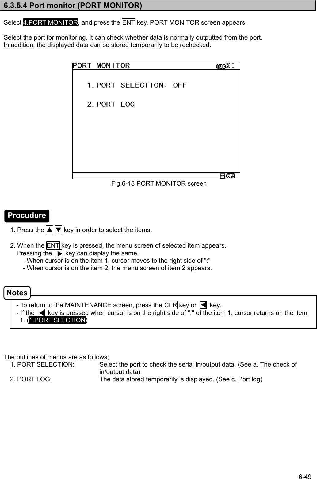
![6-50 PORT MONITOR ⅩⅠ $PRMC,012601.00,A,3541.273,N,1393 4.251,E,00.0,158.,020903,00.,W,D*2 D $GPGLL,3541.273,N,13934.251,E,0126 01.0 $GPGGA,012602.00,3541.273,N,13934. 251,E,2,08,01.0,+0050,M,+039,M,05, ,0686*5C $PRMC,012601.00,A,3541.273,N,1393 4.251,E,00.0,158.,020903,00.,W,D*2 D $GPGLL,3541.273,N,13934.251,E,0126 01.0 $GPGGA,012602.00,3541.273,N,13934. 251,E,2,08,01.0,+0050,M,+039,M,05, ,0686*5C PORT MONITOR ⅩⅠ 1. PORT MONITOR: GPS IN 2. PORT LOG a. The check of in/output data (PORT SELECTION) 1) Select 1.PORT SELECTION, and press the ENT key. Cursor moves to the right side of ":". 2) Press the ▲ ▼ key and select the following items; OFF: The monitoring of each port does not carry out. GPS IN: Input data of the GPS port DISP IN: Input data of the DISP (Option) port DISP OUT: Output data of the DISP (Option) port 3) Example - Select the “GPS IN”, and press the ENT key. PORT MONITOR menu screen changes to the data display screen. - When neither the GPS receiver nor MPD is connected to the port of “GPS IN” and “DISP IN”, nothing is displayed on the data display screen. b. Store the displaying data temporarily 1) Press the * key. The sub screen appears. 2) Select the “[START]”, and press the ENT key. Storing of the displaying data is started. During storing, the following is displayed on the screen title. “ NOW LOGGING... “ - When the MENU, DISP or USER key is pressed, storing of the displaying data is stopped. - Data is recordable to two screens. - Data is stored until it turns off the power. 3) For canceling, select the “[STOP]” and press the ENT key. The sub screen is closed, and storing of the displaying data is stopped. ENTCLRPORT MONITOR ⅩⅠ $PRMC,012601.00,A,3541.273,N,1393 4.251,E,00.0,158.,020903,00.,W,D*2 D $GPGLL,3541.273,N,13934.251,E,0126 01.0 $GPGGA,012602.00,3541.273,N,13934. 251,E,2,08,01.0,+0050,M,+039,M,05, ,0686*5C $PRMC,012601.00,A,3541.273,N,1393 4.251,E,00.0,158.,020903,00.,W,D*2 D $GPGLL,3541.273,N,13934.251,E,0126 01.0 $GPGGA,012602.00,3541.273,N,13934. 251,E,2,08,01.0,+0050,M,+039,M,05, ,0686*5C *PORT MONITOR* [START] [STOP] Procudure Procudure Notes Notes](https://usermanual.wiki/Japan-Radio/NCR-333/User-Guide-571910-Page-82.png)
![6-51 PORT LOG ⅩⅠ $PRMC,012601.00,A,3541.273,N,1393 4.251,E,00.0,158.,020903,00.,W,D*2 D $GPGLL,3541.273,N,13934.251,E,0126 01.0 $GPGGA,012602.00,3541.273,N,13934. 251,E,2,08,01.0,+0050,M,+039,M,05, ,0686*5C $PRMC,012601.00,A,3541.273,N,1393 4.251,E,00.0,158.,020903,00.,W,D*2 D $GPGLL,3541.273,N,13934.251,E,0126 01.0 $GPGGA,012602.00,3541.273,N,13934. 251,E,2,08,01.0,+0050,M,+039,M,05, ,0686*5C PORT LOG ⅩⅠ 1.PORT MONITOR: GPS IN 2. PORT LOG c. Port log(PORT LOG) 1) Select 2.PORT LOG, and press the ENT key. PORT LOG screen appears. The data stored in the PORT MONITOR is displayed on this screen. 2) “ “ mark is displayed on the bottom line when the PORT LOG screen is able to scroll downward. - “ “ mark is displayed on the top line when the PORT LOG screen is able to scroll upward. Press the ▲ ▼ key and scroll the viewing area. Press the * key. The sub screen appears. To print the setting status to the external printer, select the “[PRINT OUT]”, and press the ENT key. To stop printing, press the CLR key while printing. To output the status data to serial ports, select the “[DATA OUT]”, and press the ENT key. To stop outputting, press the CLR key while data outputting. To return to the PORT LOG screen, select the “[CANCEL]” and press the ENT key. - All the character strings displayed on the PORT LOG screen are printed. ENTCLRPORT LOG ⅩⅠ $PRMC,012601.00,A,3541.273,N,1393 4.251,E,00.0,158.,020903,00.,W,D*2 D $GPGLL,3541.273,N,13934.251,E,0126 01.0 $GPGGA,012602.00,3541.273,N,13934. 251,E,2,08,01.0,+0050,M,+039,M,05, ,0686*5C $PRMC,012601.00,A,3541.273,N,1393 4.251,E,00.0,158.,020903,00.,W,D*2 D $GPGLL,3541.273,N,13934.251,E,0126 01.0 $GPGGA,012602.00,3541.273,N,13934. 251,E,2,08,01.0,+0050,M,+039,M,05, ,0686*5C *PORT LOG* [PRINT OUT] [DATA OUT] [CANCEL] Procudure Notes](https://usermanual.wiki/Japan-Radio/NCR-333/User-Guide-571910-Page-83.png)
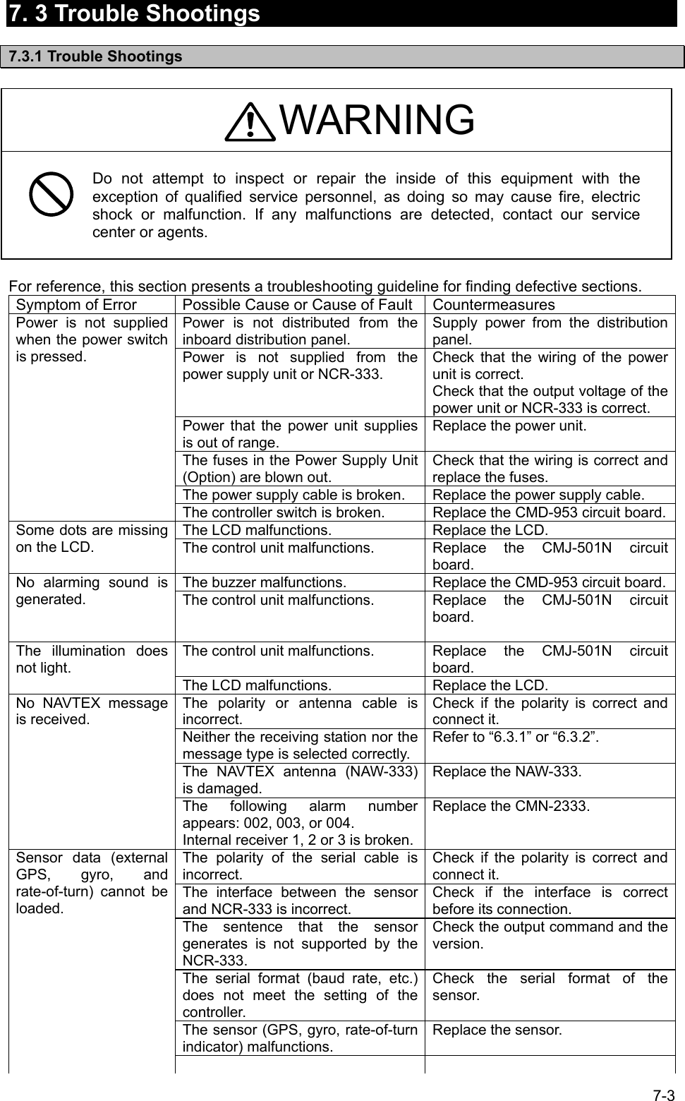
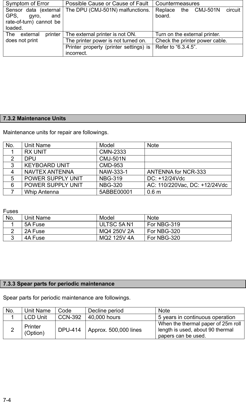
![8-1 8. AFTER-SALES SERVICE Warranty z Warranty period is one year from the purchase day. Warranty z Keeping period of maintenance parts is ten years from the production is discontinued. Before returning repair If what appears to be a malfunction is detected, refer to “7.3 Troubleshooting” to check if the equipment is actually defective before requesting repair. If the defect persists, immediately stop operation and call our service center or agents. z During the warranty period, our agencies or we will repair the malfunction without any fee, according to the specified procedure. z After the warranty expires, we will repair the malfunction for a fee, if repair is possible. In this case, send the parts or we’ll repair onboard in a specified port. The parts may be repaired in a plant if it’s unrepairable onboard. z Item for notification Product name, type, manufactured data, serial number, information about the malfunction (the more detailed, the better), information about the alarm number and software version, your company or organization name, address and phone number. Periodical maintenance recommendation Performance of this equipment may degrade over time because parts wear out, although degradation depends on how this unit has been maintained. We recommend periodic professional maintenance checks in addition to daily maintenance. Call our service center or agents for periodic professional maintenance (This maintenance requires a service charge). Call our office or the nearest agency for detailed information about after-sales service. [JRC offices or the nearest agency] See the List of JRC offices or the nearest agency at the end of this manual.](https://usermanual.wiki/Japan-Radio/NCR-333/User-Guide-571910-Page-89.png)