Japan Radio NCR-333 Marine NAVTEX Receiver User Manual
Japan Radio Co Ltd. Marine NAVTEX Receiver
Instruction Manual

NAVTEX Receiver
NCR-333
Instruction Manual
7ZPJD0304

i
Preface
Thank you for purchasing NCR-333 NAVTEX Receiver.
The NAVTEX receiver automatically receives NAVTEX service broadcasts supplied in English
and other optional languages.
• Be sure to read this manual for full comprehension before using the equipment.
• Save this manual near at hand for quick reference in the future.
Make use of this manual when experiencing operation difficulties.
ii
WARNING
Before Operation
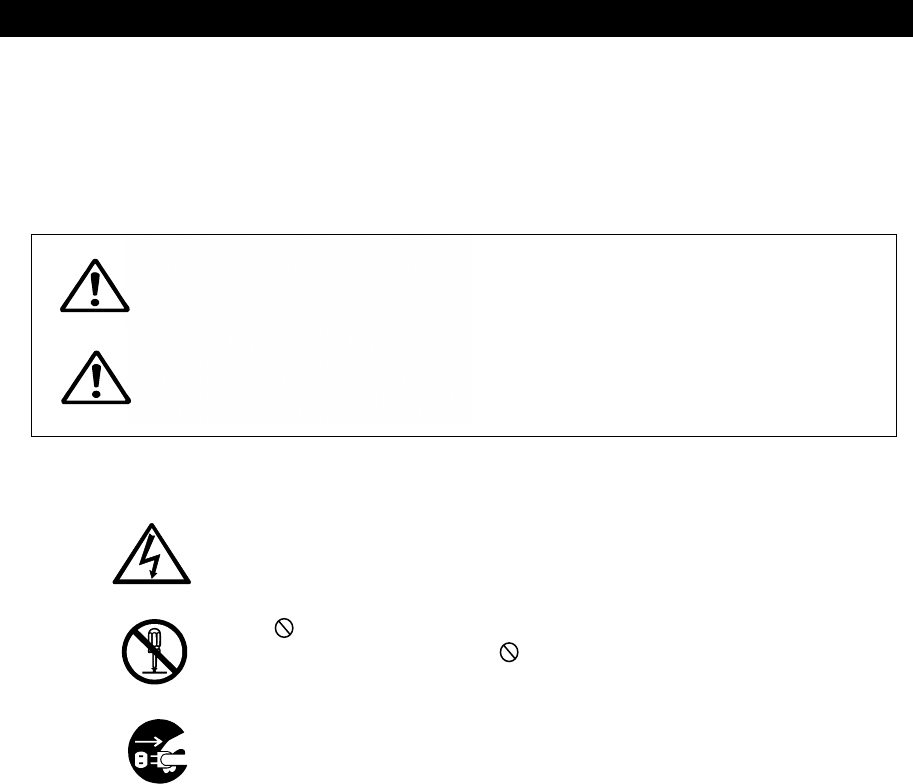
Concerning the symbols
This manual uses the following symbols to explain correct operation and to prevent
injury or damage to property.
The symbols and descriptions are as follows. Understand them before proceeding with
this manual.
Indicates a warning that, if ignored, may
result in serious injury or even death.
Indicates a caution that, if ignored, may
result in injury or damage to property.
Examples of symbols
The △ symbol indicates caution (including DANGER and WARNING).
The illustration inside the △ symbol specifies the content of the caution
more accurately. (This example warns of possible electrical shock.)
The symbol indicates that performing an action is prohibited.
The illustration inside the symbol specifies the contents of the
prohibited operation. (In this example disassembly is prohibited.)
The ● symbol indicates operations that must be performed.
The illustration inside the ● symbol specifies obligatory instructions. (In
this example unplugging is the obligatory instruction.)
CAUTION
iii
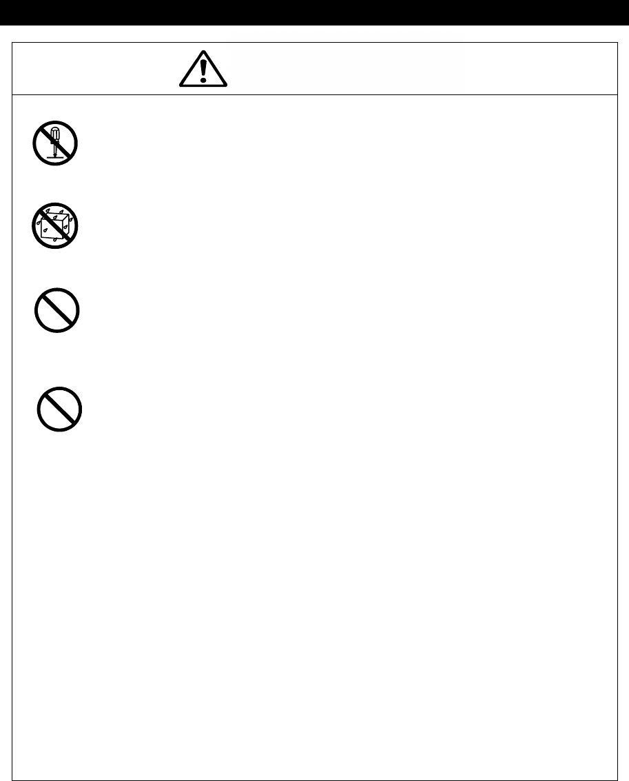
WARNING
Handling Precautions
Do not disassemble or customize this unit. Doing so may cause fire,
electrical shock or malfunction.
Do not get this equipment wet or spill any liquids on or near this equipment.
Doing so causes electrical shock or malfunction.
Do not use a voltage other than specified. Doing so may cause fire,
electrical shock or malfunction.
Do not attempt to inspect or repair the inside of this equipment with the
exception of qualified service personnel, as doing so may cause fire, electric
shock or malfunction. If any malfunctions are detected, contact our service
center or agents.
iv
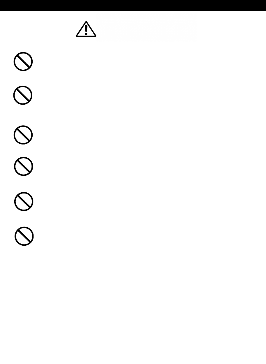
CAUTION
Handling Precautions
Do not use this equipment for anything other than specified.
Doing so may cause malfunction or damage to persons.
Do not adjust the trimmer resistors or the trimmer capacitors on the PCB
unit.
Doing so may cause malfunction or damage to persons. They are preset at
the factory.
Do not install this equipment in a place other than specified or in one with
excessive humidity, steam, dust or soot. Doing so may cause fire, electric
shock, malfunction or damage to persons.
Do not place this equipment anywhere vibration or impact is likely to occur.
Doing so may cause a fall or damage to property and persons.
Do not place any objects on this equipment.
Doing so may cause a fall, malfunction or damage to property and persons.
Leave installation of this equipment to our service center or agents.
Installation by an unauthorized person may lead to malfunction.
v
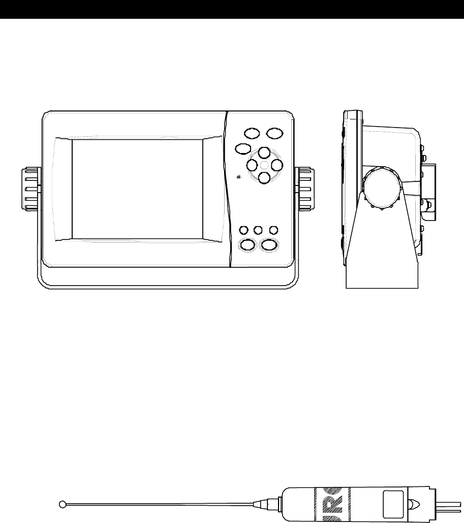
External Views
NCR-333 NAVTEX Receiver
NAW-333 NAVTEX Antenna
vi
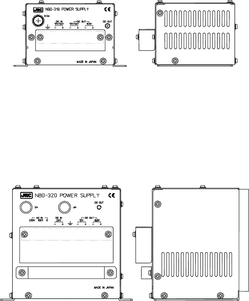
NBG-319 Power Supply Unit
NBG-320 Power Supply Unit

vii
CONTENTS
Preface .................................................................................................................. i
Before Operation .................................................................................................. ii
Handling Precautions ........................................................................................... iii
External Views ...................................................................................................... v
1. GENERAL ..................................................................................................... 1-1
1.1 Outlines .................................................................................................... 1-1
1.2 Features ................................................................................................... 1-1
1.3 Components ............................................................................................. 1-2
1.3.1 Standard Components .......................................................................... 1-2
1.3.2 Options ................................................................................................. 1-2
1.3.3 Configuration ......................................................................................... 1-3
1.4 Outline ..................................................................................................... 1-4
2. INSTALLATION DIAGRAM ............................................................................ 2-1
3. PART NAMES AND FUNCTIONS ................................................................. 3-1
3.1 NCR-333 NAVTEX Receiver .................................................................... 3-1
4. DISPLAYS ..................................................................................................... 4-1
4.1 Displays ................................................................................................... 4-1
4.1.1 Message text screen ............................................................................. 4-1
4.1.2 Message list 1 screen ........................................................................... 4-2
4.1.3 Message list 2 screen ........................................................................... 4-2
4.1.4 Save message list screen ..................................................................... 4-3
4.1.5 Position/date screen ............................................................................. 4-3
4.1.6 Setup screen ......................................................................................... 4-4
5. INSTALLATION ............................................................................................. 5-1
5.1 Installation ................................................................................................ 5-1
5.1.1 Selection of location .............................................................................. 5-1
5.1.2 Mounting ............................................................................................... 5-1
6. OPERATION .................................................................................................. 6-1
6.1 Menu Tree ................................................................................................ 6-1
6.2 Basic Operation ....................................................................................... 6-2
6.2.1 Turning ON the power............................................................................. 6-2
6.2.1.1 Start up (Normal) ................................................................................ 6-2
6.2.1.2 Start up (Abnormal-1) ......................................................................... 6-3
6.2.1.3 Start up (Abnormal-2) ......................................................................... 6-3
6.2.1.4 Start up (Abnormal-3) ......................................................................... 6-4
6.2.2 Turning OFF the power........................................................................... 6-4
6.2.3 Backlight adjustment............................................................................... 6-5
6.2.4 Contrast adjustment .............................................................................. 6-5
6.2.5 Alarm ...................................................................................................... 6-6
6.2.6 Screen switching..................................................................................... 6-6
6.2.7 Displaying the message.......................................................................... 6-7
6.2.7.1 Message text ...................................................................................... 6-7
6.2.7.2 Message list 1 .................................................................................. 6-13
6.2.7.3 Message list 2 .................................................................................. 6-21
6.2.7.4 Save message list ............................................................................ 6-22

viii
6.3 MAIN MENU .......................................................................................... 6-24
6.3.1 RX STATION screen ........................................................................... 6-25
6.3.1.1 Receiving mode setting (RX MODE)................................................. 6-26
6.3.1.2 Receiving channel setting (OPERATING FREQ.) ............................. 6-26
6.3.1.3 Automatic receiving station selection (AUTO MODE SETTING) ....... 6-27
6.3.1.4 Manual receiving station selection (MANUAL MODE SETTING) ...... 6-31
6.3.2 Receiving message type settings (MESSAGE TYPE SETTING) ......... 6-32
6.3.3 DISPLAY setting menu (DISPLAY SET) ............................................. 6-33
6.3.3.1 Contrast adjustment (CONTRAST) ................................................. 6-34
6.3.3.2 Brightness settings (DIMMER) ........................................................ 6-34
6.3.3.3 Buzzer settings (BUZZER) .............................................................. 6-34
6.3.3.4 Time Difference setting (LOCAL TIME) ........................................... 6-35
6.3.3.5 Assigning to the USER key (USER KEY SETTING) ....................... 6-36
6.3.3.6 POSITION/TIME screen settings (POS/TIME DISP.SET) ............... 6-37
6.3.4 NAVTEX setting menu (NAVTEX) ...................................................... 6-38
6.3.4.1 Character size setting (CHARACTER SIZE) ................................... 6-39
6.3.4.2 CER setting (CER DISP.SETTING) ................................................. 6-39
6.3.4.3 Automatic scrolling setting (MESSAGE SCROLL) ............................ 6-40
6.3.4.4 Scrolling speed adjustment (MESSAGE SPEED) ............................. 6-40
6.3.4.5 External printer settings (PRINTER PROPERTY) ............................. 6-41
6.3.5 MAINTENANCE menu (MAINTENANCE)............................................ 6-42
6.3.5.1 Self Diagnosis (SELF DIAGNOSIS) .................................................. 6-43
6.3.5.2 NAVTEX alarms (NAVTEX ALARM).................................................. 6-46
6.3.5.3 Setting status of the NAVTEX Receiver (STATUS) ........................... 6-48
6.3.5.4 Port monitor (PORT MONITOR)........................................................ 6-49
6.3.5.5 Software version (SOFTWARE VERSION) ....................................... 6-52
6.3.6 The display language setting (LANGUAGE) ........................................ 6-52
7. MAINTENANCE AND INSPECTION ............................................................. 7-1
7.1 General Maintenance and Inspection ...................................................... 7-1
7.2 Periodic Inspection .................................................................................. 7-2
7.2.1 Confirming the Rx station and Message type ...................................... 7-2
7.2.2 Confirming the Alarm Status................................................................... 7-2
7.3 Trouble Shootings ..................................................................................... 7-3
7.3.1 Trouble Shootings .................................................................................. 7-3
7.3.2 Maintenance Units ................................................................................. 7-4
7.3.3 Spear parts for periodic maintenance..................................................... 7-4
8. AFTER-SALES SERVICE ............................................................................. 8-1
Before returning repair .................................................................................. 8-1
Periodical maintenance recommended ......................................................... 8-1
9. SPECIFICATIONS ........................................................................................ 9-1
9.1 General (NCR-333) ................................................................................. 9-1
9.1.1 Receiver ............................................................................................... 9-1
9.1.2 Operation panel .................................................................................... 9-1
9.1.3 Power supply ........................................................................................ 9-1
9.1.4 External interfaces ................................................................................ 9-1
9.1.5 Environmental condition ....................................................................... 9-2
9.1.6 Supported interface sentences ............................................................. 9-2
9.1.7 Received message log ......................................................................... 9-2
9.2 NAVTEX ANTENNA (NAW-333 - Option) ................................................ 9-3
9.2.1 Electrical characteristics ....................................................................... 9-3
9.2.2 Environmental condition ....................................................................... 9-3
ix
9.3 POWER SUPPLY UNIT (NBG-320 - Option) ........................................... 9-3
9.4 POWER SUPPLY UNIT (NBG-319 - Option) ........................................... 9-3
x

1-1
1. GENERAL
1.1 Outlines
The NAVTEX NCR-333 function receives and displays the various types of information broadcast
at frequencies of 518 kHz, 490 kHz and 4209.5 kHz, such as: navigational warning,
meteorological warning, search and rescue information, and other types of information. NCR-333
also provides the function that selects information type and coast station for intended uses.
1.2 Features
● Receiving NAVTEX broadcasts
━━━━━━━━━━━━━━━━━━━━━━━━━━━━━━━━━━━━━━━━━━━
NCR-333 receives NAVTEX broadcasts automatically on 518 kHz, 490 kHz, and 4209.5 kHz.
● Large screen allows comfortable visibility
━━━━━━━━━━━━━━━━━━━━━━━━━━━━━━━━━━━━━━━━━━━
NCR-333 has a 5.7-inch LCD screen display with clear visibility.
It also provides three different character sizes of display, and can be selected at your
convenience.
● Message saving function
━━━━━━━━━━━━━━━━━━━━━━━━━━━━━━━━━━━━━━━━━━━
NCR-333 can store up to 200 message identification codes for 70 hours. Moreover, the stored
message of each channel can be saved up to 50 messages permanently.
● Automatically receiving station setting function
━━━━━━━━━━━━━━━━━━━━━━━━━━━━━━━━━━━━━━━━━━━
NCR-333 can select receiving stations automatically on GPS position data is valid.
● Permanent storage of data settings
━━━━━━━━━━━━━━━━━━━━━━━━━━━━━━━━━━━━━━━━━━━
NCR-333 can set and store the message type and seashore station that receive to internal
memory. The data, therefore, does not need to be re-set, even after power has been turned off.
● Dual voltage supply input
━━━━━━━━━━━━━━━━━━━━━━━━━━━━━━━━━━━━━━━━━━━
NCR-333 can be used on wither 24 VDC or 12 VDC vessels.
● Self-diagnosis Function
━━━━━━━━━━━━━━━━━━━━━━━━━━━━━━━━━━━━━━━━━━━
NCR-333 has automatic self-diagnosis function. This function allows easy maintenance and high
system reliability.
● Connection to external equipment
━━━━━━━━━━━━━━━━━━━━━━━━━━━━━━━━━━━━━━━━━━━
NCR-333 can be used with the JRC Total Navigator (ECDIS) and external serial printers.
1-2
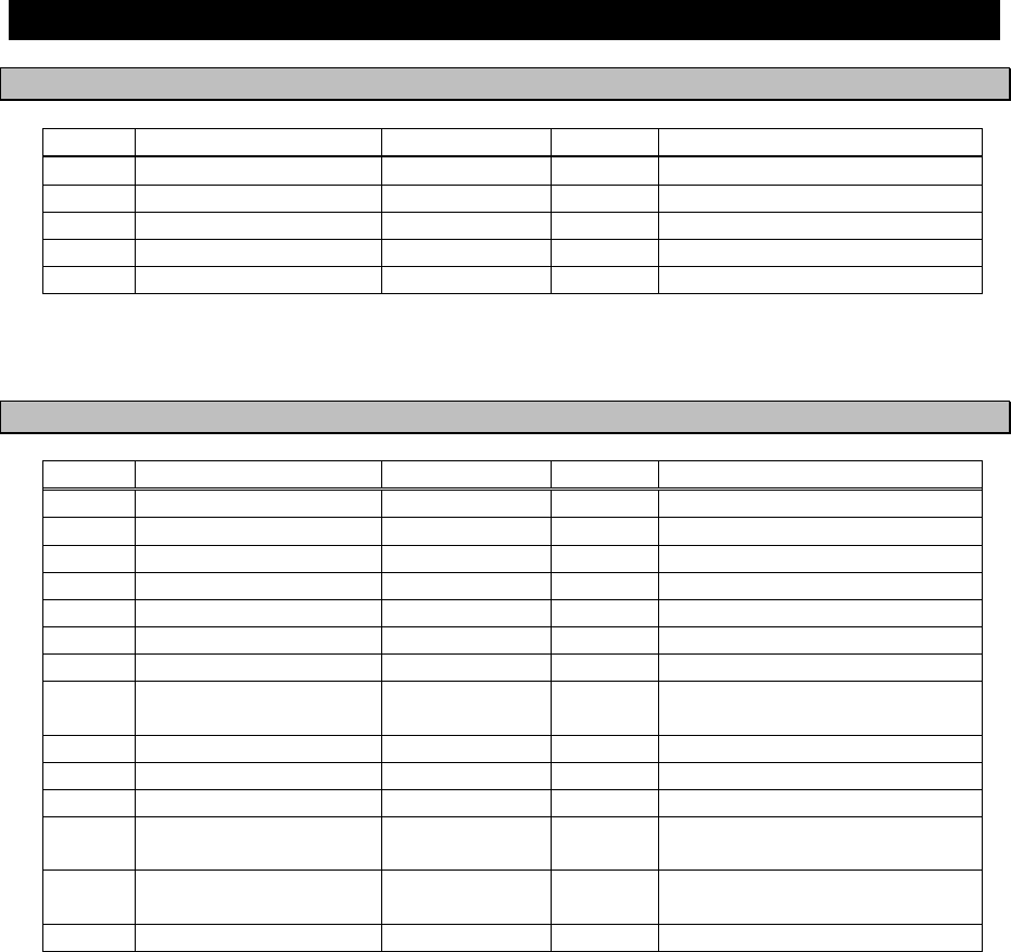
1.3 Components
1.3.1 Standard Components
No. Name Type Quantity Remarks
1 NAVTEX Receiver NCR-333 1
2 Tapping screws MPTG31659 1 4 tapping screws
3 Instruction manual 7ZPJD0304 1 Present volume
4 Operation card 7ZPJD0306 1
5 Antenna cable 7ZCJD0251 1 0.5 m
1.3.2 Options
No. Options Type Quantity Remarks
1 NAVTEX Antenna NAW-333 1 Whip antenna for NCR-333
2 Power supply unit NBG-319 1 12 / 24VDC input
3 Power supply unit NBG-320 1 100/220VAC Manual Setting
4 External printer DPU-414 1
5 Printer cable 7ZCJD0254 1 D-sub 9-pin 1.5 m
6 Printer cable 7ZCJD0270 1 D-sub 9-pin 10 m
7 Printer power cable 7ZCJD0257B 1 1.5 m
8 Printer connection kit 7ZXJD0076 1 7ZCJD0257B and
2-pin terminal block
9 Printer paper 6ZCAF00252A 1 112mm x φ50mm 25m x1
10 NAVTEX buzzer CGC-300A 1 External buzzer
11 DMC NCH-321A 1 Distress Message Controller
12 External buzzer
connection kit 7ZXJD0074 1
1.5 m cable and
2-pin terminal block
13 Data connection kit 7ZXJD0075 1 1.5 m cable and
3-pin terminal block
14 Console mount kit MPBC39314 1
1-3
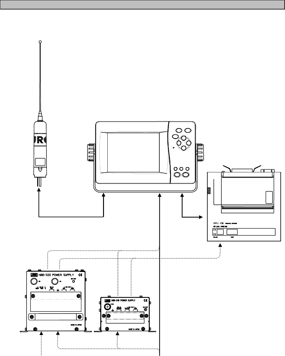
1.3.3 Configuration
• System Block Diagram
NCR-333
NAVTEX RECEIVER
NAW-333
NAVTEX ANTENNA
(OPTION)
NBG-320
POWER SUPPLY
(OPTION)
DPU-414
PRINTER
(OPTION)
DC +12/24V
AC 110/220V
NBG-319
POWER SUPPLY
(OPTION)
DC
+
12V
DC
+
6.5V
1-4
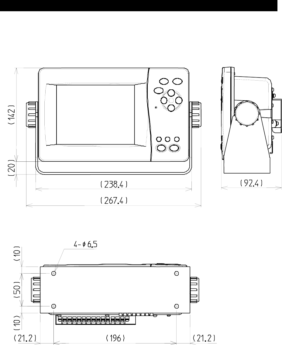
1.4 Outline
• Outline Drawing of NCR-333 NAVTEX Receiver
━━━━━━━━━━━━━━━━━━━━━━━━━━━━━━━━━━━━━━━━━━━
Unit: mm
Mass: approx. 2.1 kg
1-5
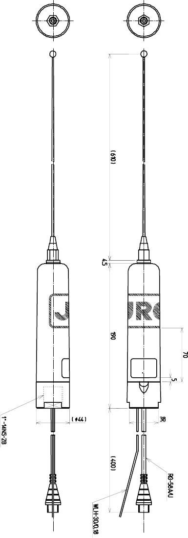
• Outline Drawing of NAW-333 NAVTEX Antenna
━━━━━━━━━━━━━━━━━━━━━━━━━━━━━━━━━━━━━━━━━━━
Unit: mm
Mass: approx. 0.3 kg
1-6
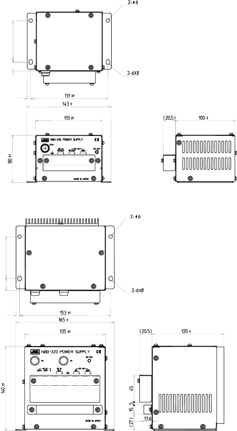
• Outline Drawing of NBG-319 Power Supply Unit
━━━━━━━━━━━━━━━━━━━━━━━━━━━━━━━━━━━━━━━━━━━
Unit: mm
Mass: approx. 0.9 kg
• Outline Drawing of NBG-320 Power Supply Unit
━━━━━━━━━━━━━━━━━━━━━━━━━━━━━━━━━━━━━━━━━━━
Unit: mm
Mass: approx. 3.3 kg
1.5
1.5
1.5
1.5
6±0.5
20±0.7 70±0.5
6±0.5
70±0.5 15±0.7
1-7
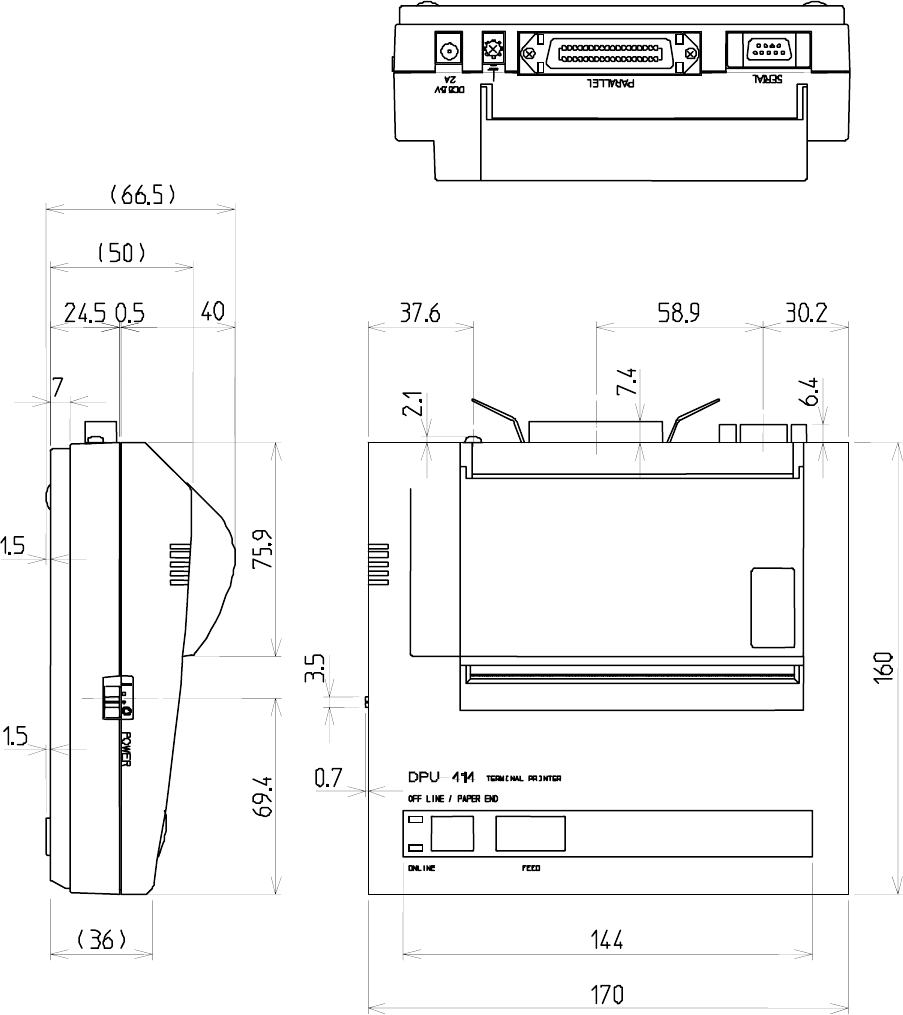
• Outline Drawing of DPU-414 Printer
━━━━━━━━━━━━━━━━━━━━━━━━━━━━━━━━━━━━━━━━━━━
Unit: mm
Mass: approx. 0.7 kg
1-8
2-1
CAUTION
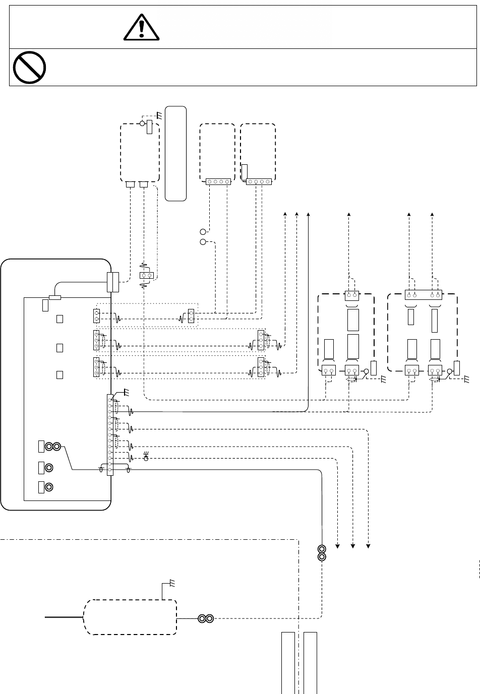
2. INSTALLATION DIAGRAM
Notes:
Leave installation of this system to our service center or agents.
Installation by an unauthorized person may result in malfunction.
*RG-10UY
50m max.
BELOW DECK
ABOVE DECK
*1 x 2 x 0.75mm
2
(JIS TTYCS-1)
*1 x 2 x 0.75mm
2
(JIS TTYCS-1)
*2 x 1.5mm
2
(JIS DPYC-1.5)
MF/HF RADIO EQUIPMENTS
INS / (D)GPS RECEIVER (IEC61162-1)
INS / ECDIS (IEC61162-1)
Note1: * marked cables are supplied by dock yard
COAXIAL CABLE
AND CONNECTOR
(ATTACHMENT)
Note2: marked components are optional
*1 x 2 x 0.75mm
2
(JIS TTYCS-1)
RG-58A/U
0.42m Typ.
7ZCJD0251
(Cable Length = 0.5m)
RX-A
-BK
RX-B
GND-ISO
TX-B
TX-A
DC+
GND-ISO
+BK
-ANT
+ANT
DC -
GND
J1
NCR-333
NAVTEX RECEIVER
1
13
13
J151 J153J152
Hi-Z 50ohm
NAVTEX
ANTENNA
TX-B
TX-A
GND-ISO
J3
13
TX-B
TX-A
GND-ISO
J2
12
EXT ALM-
EXT ALM+
DATA OUT2 EXT ALMDISP
CMN-2333
RX UNIT
J502
PRINTER / MAINTENANCE
DPU-414
PRINTER
NBG-319
POWER SUPPLY
DC12/24V
IN
+
-
EMERGENCY
POWER SOURCE
DC+12/24V
*2 x 1.5mm
2
(JIS DPYC-1.5)
REMOTE MAINTENANCE
SERVER
MULTI PURPOSE DISPLAY
CGC-300A
NAVTEX
BUZZER
+
1
2
3
EXT ALM+
EXT ALM-
*1 x 2 x 0.75mm
2
(JIS TTYCS-1)
*1 x 2 x 0.75mm
2
(JIS TTYCS-1)
DC12/24V
OUT
GND
*
+
-
+
-
DC6.5V
OUT
Printer Connection KIT
7ZXJD0076
(Cable Length = 1.5m)
EMERGENCY
POWER SOURCE
DC+12/24V
7ZCJD0254
(Cable Length = 1.5m)
or
7ZCJD0270
(Cable Length = 10m)
+-
* POWER SOURCE
DC+12/24V
*2 x 1.5mm
2
(JIS DPYC-1.5)
Maximum cable length between
NBG-319/320 and DPU-414 is 10m
Connector: N-P-10U
(JRC Supply)
Connector: N-P-10U
(JRC Supply)
WLH-30/0/18-U-5
(ATTACHMENT)
GND
*
7ZXJD0074
(Cable Length = 1.5m)
EXT ALM Connection KIT
DATA Connection KIT
7ZXJD0075
(Cable Length = 1.5m)
DATA Connection KIT
7ZXJD0075
(Cable Length = 1.5m)
7ZCJD0257B: Cable only
(Cable Length = 1.5m)
NAW-333
NAVTEX ANTENNA
NCH-321A
DMC
27 DAL
28 S-GND
29 DAL
30 DAL +
TB10
EXT ALM+
EXT ALM-
*2 x 1.5mm
2
(JIS DPYC-1.5)
*2 x 1.5mm
2
(JIS DPYC-1.5)
AC IN
DC24V IN
+
-
DC12V
OUT
U
V
EMERGENCY
POWER SOURCE
AC110/220V
EMERGENCY
POWER SOURCE
DC+24V
*2 x 1.5mm
2
(JIS DPYC-1.5)
*2 x 1.5mm
2
(JIS DPYC-1.5)
+
-
DC6.5V
OUT
GND
*
+
-
*
NBG-320
POWER SUPPLY
2-2
3-1
3. PART NAMES AND FUNCTIONS
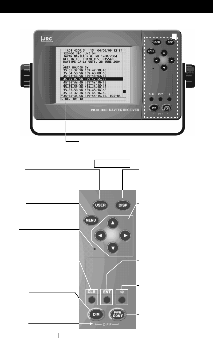
3.1 NCR-333 NAVTEX Receiver
Frontview
LCD Panel
For further information, refer to “● Display indicators” and “4. DISPLAY”.
DIMMER Key
Adjusts the back light brightness of the
LCD.
Key
Displays the small window.
ENTER Key
Determines selection of an item and fixes
a setup.
CLR Key
Clears input errors or cancel operations.
Turns off the buzzer sound.
MENU Key
Displays the “Main Menu”.
Buzzer
POWER/CONTRAST Key
Turns the power ON. Adjusts the contrast
of the LCD while power is turned on.
Power Off
Turns the power off with pressing the
PWR/CONT key and the DIM key at the
same time.
USER Key
Displays the screen assigned to this key.
Refer to "6.3.3.5 USER KEY" about the
setting of USER key.
A: Key Panel
Up, Down, Left, Right Key
Moves the cursor, scrolls the display
screen, and selects the item.
DISP Key
Changes the screen, refer to “4. DISPLAY”.
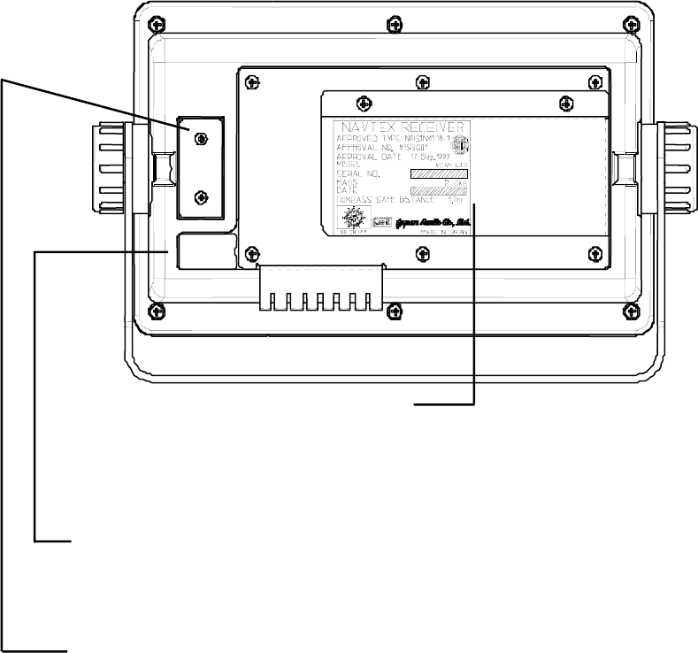
3-2
Rear view
External equipments connector
ECDIS, external buzzer, and MPD (Multi purpose display) cables are connected to the connector.
Printer/Maintenance connector
Serial printer and Maintenance PC cables are connected to the connector.
Protective cover
To connect the antenna cable and the power cable, remove this cover.
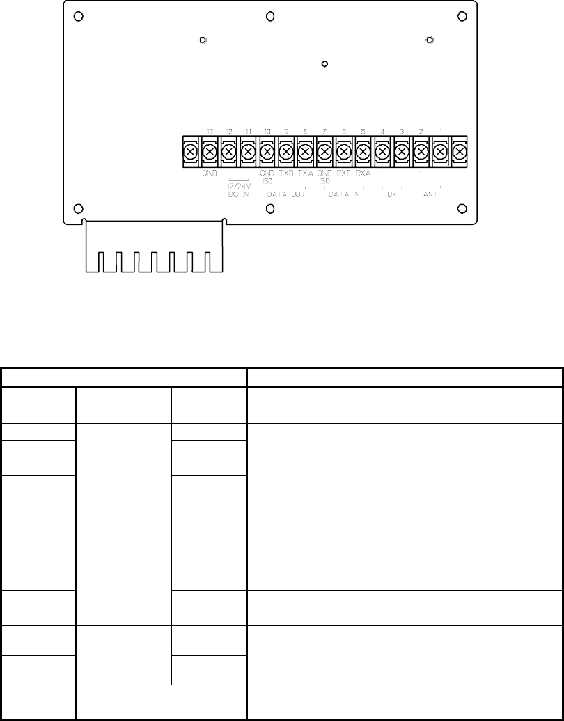
3-3
Rear panel (Terminal)
Terminal Number and Name Description
1 ANT +
2 ANT ANT - Connect an antenna cable.
3 BK +
4 BK BK -
Connect the key lines leading from the
transmitter.
5 RXA
6 RXB
Connect the INS / External GPS cable for serial
communication.
7
DATA IN
GND ISO Connect the isolated signal ground cable for
serial communication.
8 TXA
9 TXB
Connect the INS cable for serial communication
with INS.
10
DATA OUT
GND ISO Connect the isolated signal ground cable for
serial communication.
11 +
12
12/24V
DC IN -
Connect the power supply cable.
The voltage range of the power supply between
10.8 and 35.0 VDC.
13 GND This terminal is for electrical grounding to the
vessel.
+
―
+
―
+
―
3-4
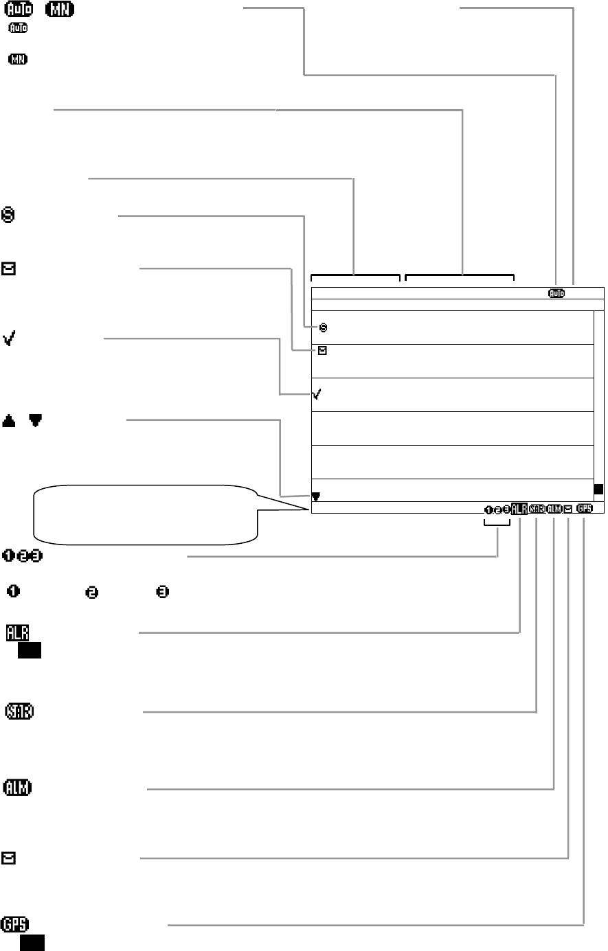
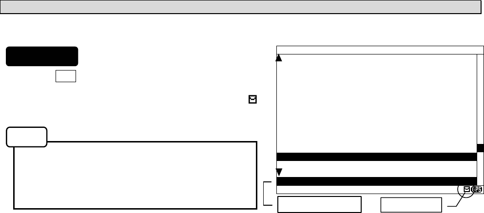
Display indicators
Alarm message
When an alarm message (MSG TYP: A,B,L) is received
with the buzzer sound.
NAVTEX Alarm
‘ALR’ is displayed while NAVTEX alarm has occurred.
Refer to “6.3.5.2 NAVTEX alarm”.
Unread message
Unread messages exist.
Receiving message
The channel number is displayed while receiving message on the channel.
: 518kHz: 490kHz: 4209.5kHz
Save message
This message has been saved.
Unread message
Unread message is stored.
Check mark
Refer to ”6.2.7.2 Message list 1”.
Display title
The title of the current screen
SORT
Displays the sorting order of the message list.
Refer to “6.2.7.2 Message list 1”.
SAR message
When a search and rescue (SAR) message is received
with the buzzer sound.
GPS position data
"GPS" is displayed while external GPS position data has input.
Station selection mode
: "AUTO MODE"is selected for coast station
selection.
: "MANUAL MODE"is selected for coast station
selection.
ⅤⅢ NAVAREA No.
The NAVAREA number is displayed with
position data input.
MSG LIST SORT:MSG TYPE
ⅤⅢ
ID FREQ LINES DATE TIME
IA01 4209.5 15 04/06/09 12:34
STATION : YOKOHAMA
MSG TYPE: NAVIGATIONAL WARNINGS
KA04 518 10 04/06/09 10:34
STATION : KUSIRO
MSG TYPE: NAVIGATIONAL WARNINGS
IA07 490 20 04/06/09 09:34
STATION : YOKOHAMA
MSG TYPE: NAVIGATIONAL WARNINGS
KC10 490 12 04/06/09 05:34
STATION : KUSIRO
MSG TYPE: ICE REPORTS
KH13 518 5 04/06/09 05:34
STATION : KUSIRO
MSG TYPE: LORAN MESSAGE
KP16 518 9 04/06/09 01:34
STATION : KUSIRO
DATA:321/342
Arrow mark
‘’ ‘’marks are displayed on the top/ bottom
line when the display screen is able to scroll
upward/downward.
Status bar
Displays alarm, received message
type and other status
4-1
4. DISPLAYS
4.1 Displays
Each time the DISP key is pressed, the screen is switched in the order below:
Message text -> Message list 1 -> Message list 2 -> Save message list -> Position/date -> ...
After NCR-333 is started, a message text screen is displayed.
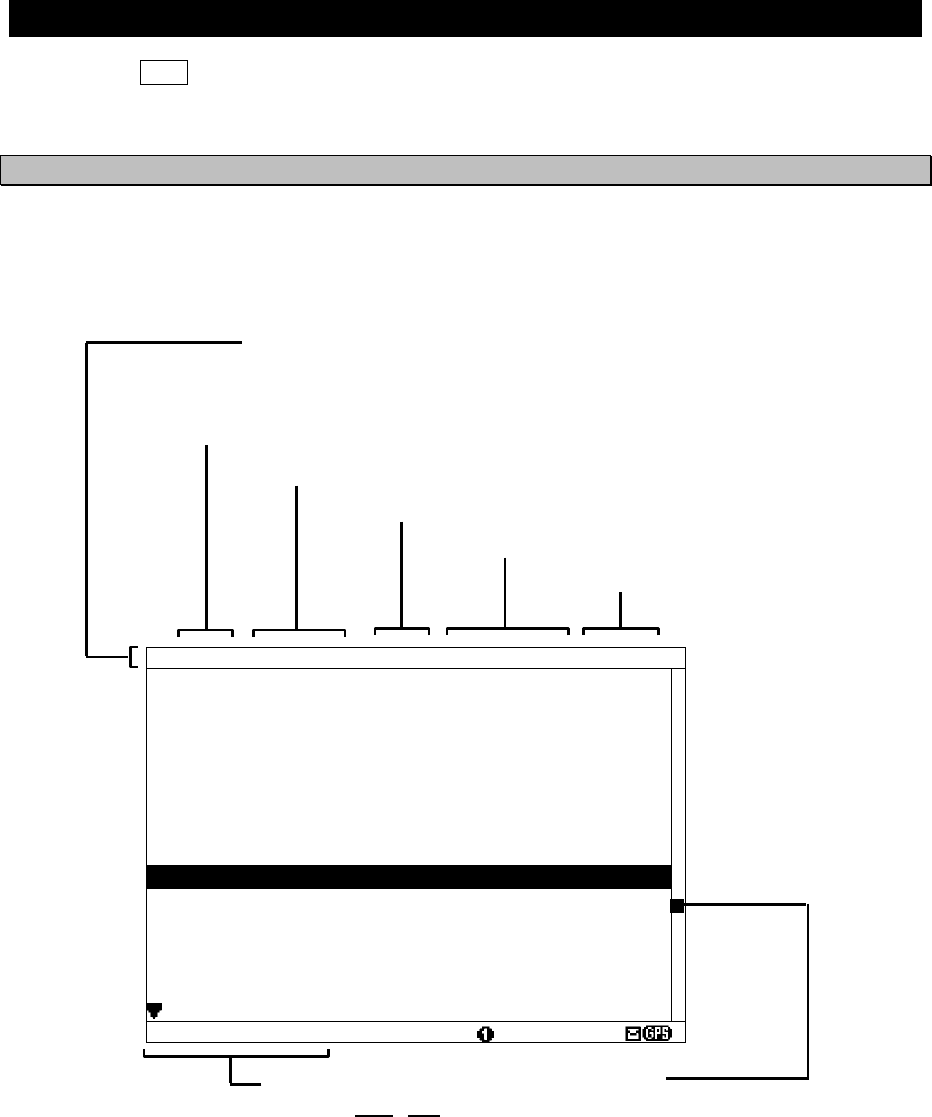
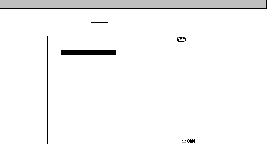
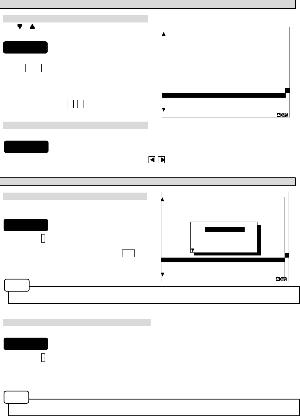
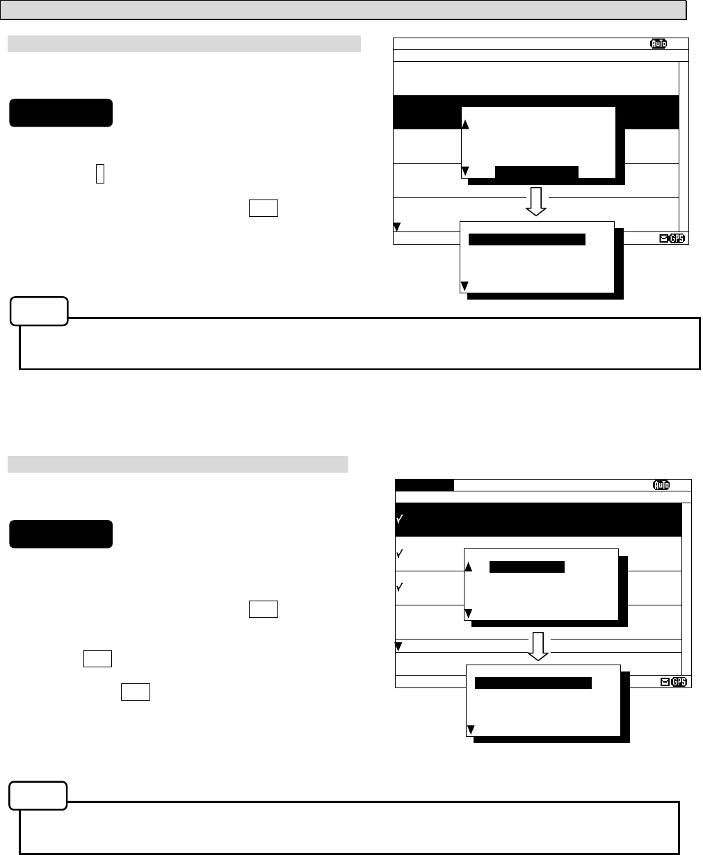
4.1.1 Message text screen
Message text screen displays the text of the received message.
This screen is displayed after NCR-333 is turned on, or after receiving a message.
IA01 4209.5 18 31/10/06 12:34
123400 UTC JUNE 04
JAPAN NAVTEX N.W. NR 1260/2004
KEIHIN KO, TOKYO WEST PASSAGE.
DAYTIME DAILY UNTIL 28 JUNE 2004
.
AREA BOUNDED BY
35-35-37.9N 139-47-18.4E
35-34-58.9N 139-48-08.6E
35-34-53.9N 139-48-03.1E
35-35-02.0N 139-47-55.3E
35-35-32.3N 139-47-16.6E
35-35-35.0N 139-47-15.1E
35-33-37.9N 139-46-18.4E
35-33-58.9N 139-46-16.6E
35-33-32.3N 139-45-16.6E
35-35-35.0N 139-44-15.1E, WGS-84
LINE: 10/ 18
Cursor position
LINE: 10 / 18
(a) (b)
(a) Cursor line position
(b) Total line
Scroll Bar
The cursor position on the message
text is indicated.
Title Bar
The following items are displayed.
ID: ID number of the message text
FREQ: Received channel frequency
LINES: The total line of the message text
DATE: Received date (DD/MM/YY)
TIME: Received time (UTC)
4-2
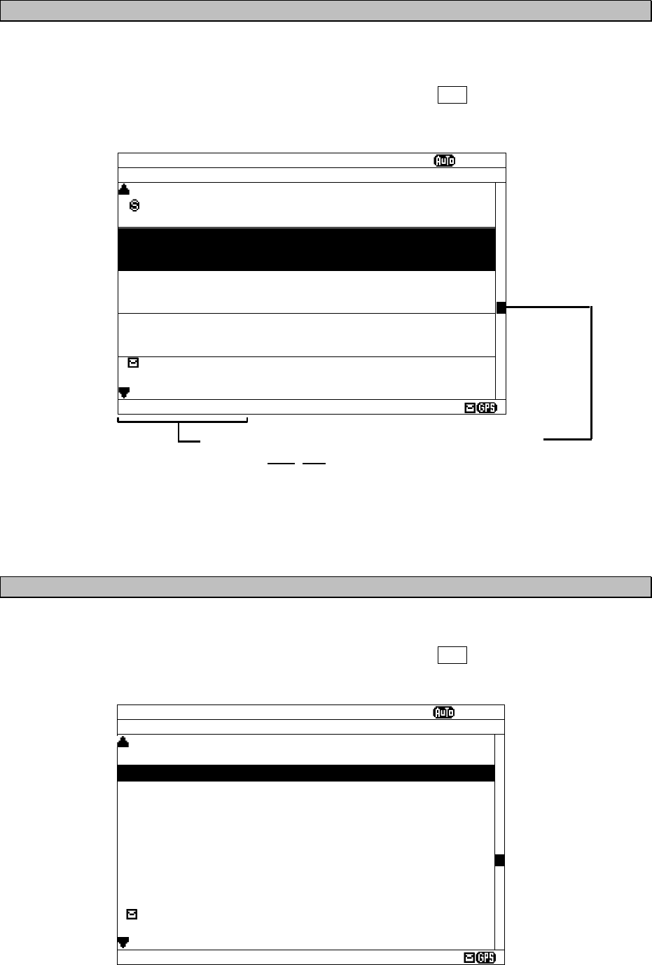
4.1.2 Message list 1 screen
Message list 1 screen displays the list of the stored messages.
This screen is displayed by indicating ID, FREQ, LINES, DATE (DD/MM/YY), TIME, STATION and
Message Type of each message.
Move the cursor up/down to select the message, and press the ENT key to display the message
text.
4.1.3 Message list 2 screen
The message list 2 displays more message indexes than the message list 1, by indicating only ID,
FREQ, LINES, DATE (DD/MM/YY), and TIME of each message.
Move the cursor up/down to select the message, and press the ENT key to display the message
text.
MSG LIST 1 SORT:MSG TYPE
ⅤⅢ
ID FREQ LINES DATE TIME
IA01 4209.5 15 04/06/09 12:34
STATION : YOKOHAMA
MSG TYPE: NAVIGATIONAL WARNINGS
KA04 518 10 04/06/09 10:34
STATION : KUSIRO
MSG TYPE: NAVIGATIONAL WARNINGS
IA07 490 20 04/06/09 09:34
STATION : YOKOHAMA
MSG TYPE: NAVIGATIONAL WARNINGS
KC10 490 12 04/06/09 05:34
STATION : KUSIRO
MSG TYPE: ICE REPORTS
KH13 518 5 04/06/09 05:34
STATION : KUSIRO
MSG TYPE: LORAN MESSAGE
DATA:321/600
Cursor position
DATA: 321 / 600
(a) (b)
(a) Cursor data position
(b) Total data
Scroll bar
The cursor position on the total
message data is indicated.
MSG LIST 2 SORT:MSG TYPE
ⅤⅢ
ID FREQ LINES DATE TIME
IA01 4209.5 15 09/06/04 12:34
IB02 490 20 09/06/04 11:34
IC03 4209.5 12 09/06/04 10:34
ID04 518 5 09/06/04 10:34
IE05 518 30 09/06/04 10:34
IF06 518 12 09/06/04 09:34
IG07 490 15 09/06/04 09:34
IH08 490 11 09/06/04 09:34
II09 4209.5 10 09/06/04 09:34
KJ10 490 20 09/06/04 05:34
KK11 518 20 04/06/04 05:34
KL12 518 14 03/06/04 05:34
KH13 518 10 02/06/04 05:34
KN14 518 7 01/06/04 05:34
KO15 518 12 28/05/04 01:34
DATA:321/600
4-3
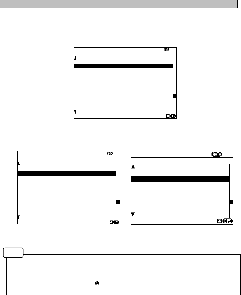
4.1.4 Save message list screen
Save message list screen displays the list of the saved messages.
This screen is displayed by indicating ID, FREQ, LINES, DATE (DD/MM/YY), TIME, STATION and
Message Type of each message.
Move the cursor up/down to select the message, and press the ENT key to display the saved
message text.
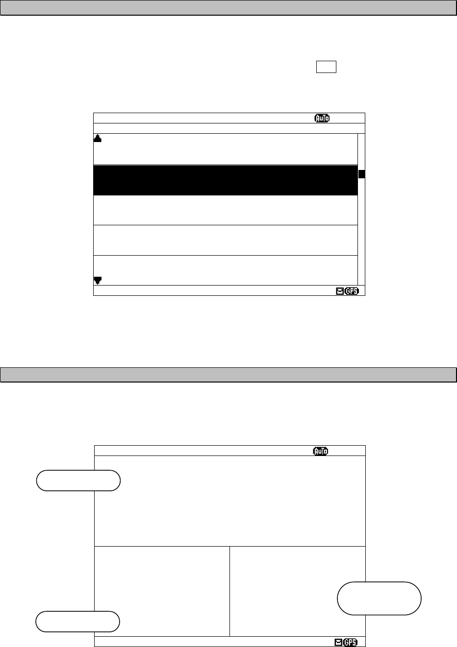
4.1.5 Position/date screen
Position/date screen displays time, position, navigational data (SOG, COG, HDG, and ROT) when
GPS data is valid.
These parameters are not displayed when no GPS data.
POS/TIME SORT:MSG TYPE
ⅤⅢ
89
°
59.999
’
N
179
°
59.999
’
E
TIME
23:59(UTC)
DATE
31/12/04
(DD/MM/YY)
SOG: 102.2KT
COG: 359.9
°
HDT: 359.9
°
ROT:+127.1
°
/MIN
Navigational
data
Date / time
Position
SAVE MSG SORT:MSG TYPE
ⅤⅢ
ID FREQ LINES DATE TIME
IA01 4209.5 15 04/06/09 12:34
STATION : YOKOHAMA
MSG TYPE: NAVIGATIONAL WARNINGS
KA04 518 10 04/06/09 10:34
STATION : KUSIRO
MSG TYPE: NAVIGATIONAL WARNINGS
IA07 490 20 04/06/09 09:34
STATION : YOKOHAMA
MSG TYPE: NAVIGATIONAL WARNINGS
KC10 490 12 04/06/09 05:34
STATION : KUSIRO
MSG TYPE: ICE REPORTS
KH13 518 5 04/06/09 05:34
STATION : KUSIRO
MSG TYPE: LORAN MESSAGE
DATA: 21/ 93
4-4
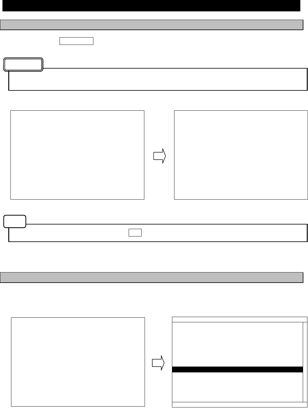
4.1.6 Setup screen
To display “Main menu”, press the MENU key.
Refer to “6.3 MAIN MENU” for NCR-333 settings
MAIN MENU
ⅤⅢ
1.RX STATION_
2.MESSAGE TYPE
3.DISPLAY
4.NAVTEX
5.MAINTENANCE
6.LANGUAGE: ENGLISH
[EXIT]
5-1
WARNING
5. INSTALLATION
5.1 Installation
5.1.1 Selection of location
The NAVTEX NCR-333 is designed so that it can be installed on either a desk, a wall, or the ceiling of the
vessel. Select an installation location that satisfies the criteria listed on the followings.
The installation location should be free from direct sunlight.
The length of the grounding wire should be minimized.
The installation location should also be: free from excessive heat, moisture, and vibration; in
case of installation on the ceiling, free from the stagnant heat as well as the above, and; in case
of installation near a window, free from salt water spray as well as the above.
The distance from the magnetic compass should be at least 1 meter.
The antenna cable, power cable, and grounding wire should be routed so as not to be in close
proximity with transmitter, radar, and other sources of electronic noise, as well as the cables of
these external units.
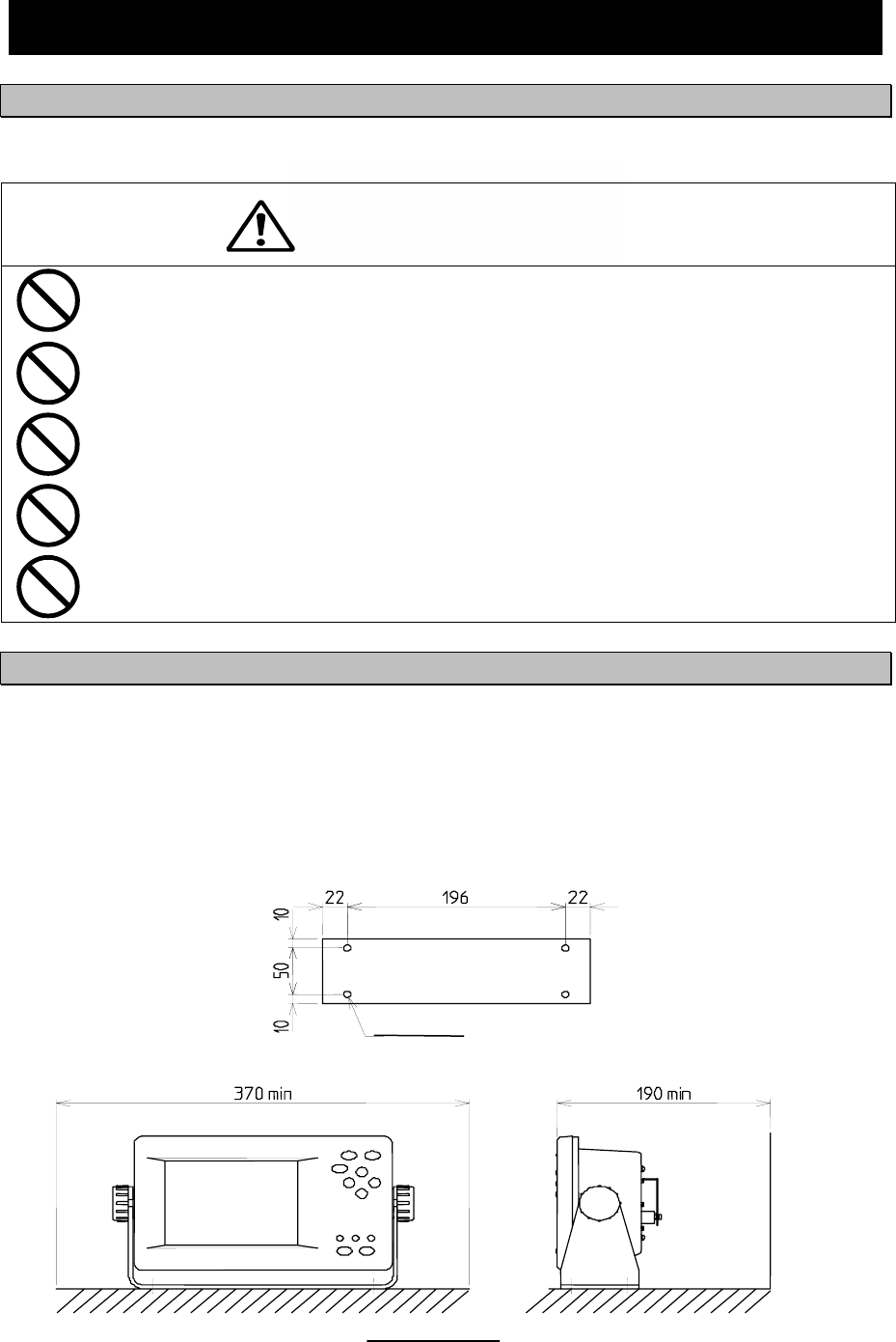
5.1.2 Mounting
Mount the NCR-333 on a table top, a bulkhead, or a ceiling by using the mounting base. Opening the case
is not necessary for mounting.
And keep a clearance for the maintenance (refer to figure below).
The mounting procedure is as follows;
- Loose the two knobs to remove the mounting base.
- Mount the mounting base on the selected location.
- Install the case on the mounting base by securing the two knobs.
CLEARANCE
Space required for receiver installation
(Unit: mm)
MOUNTING BASE (BOTTOM VIEW)
4 -φ6.5
Wall
5-2

6-1
6. OPERATION
6.1 Menu Tree
[DSPL] Key
POS/TIME
SAVE MSG LIST
MSG LIST 2
MSG LIST 1
[DSPL] key
(Power ON)
MSG VIEW
[ ], [ENT] Key [ ], [ENT] Key [ ], [ENT] Key [ ], [ENT] Key
[MENU] [CLR]
[MENU]
[ ], [CLR] Key [ ], [CLR] Key [ ], [CLR] Key [ ], [CLR] Key
MAIN MENU 1. RX STATION 1. RX MODE
2. OPERATING FREQ.
3. AUTO MODE SETTING 1. STATION (AUTO)
4. MANUAL MODE SETTING 1. STATION (MANUAL)
2. MESSAGE TYPE 1. MSG TYPE
3. DISPLAY 1. CONTRAST
2. DIMMER
- MAXIMUM
- TYPICAL
- MINIMUM
3. BUZZER
- ALARM MSG
- RECEIVED MSG
- NAVTEX ALARM
- CLICK
4. LOCAL TIME
5. USER KEY SETTING 1. USER KEY
6. POS/TIME DISP. SET
4. NAVTEX 1. CHARACTER SIZE
2. CER DISP.SETTING
3. MESSAGE SCROLL
4. MESSAGE SPEED
5. PRINTER PROPERTY
- DATA OUT
- DATA FORMAT
- BAUDRATE
- FLOW CONTROL
- PRINT DIRECTION
5. MAINTENANCE 1. SELF DIAGNOSIS 1. SELF DIAGNOSIS
2. LCD DIAGNOSIS
3. SELF DIAGNOSIS LOG
2. NAVTEX ALARM 1. ALARM HISTORY
3. STATUS 1. STATUS
4. PORT MONITOR 1. PORT SELECTION 1. MONITOR screen
2. PORT LOG 1. LOG screen
5. SOFTWARE VERSION
- PROGRAM
- LANGUAGE
- OPTION
6. LANGUAGE
[ENT
[MENU] Key
6-2
6.2 Basic Operation
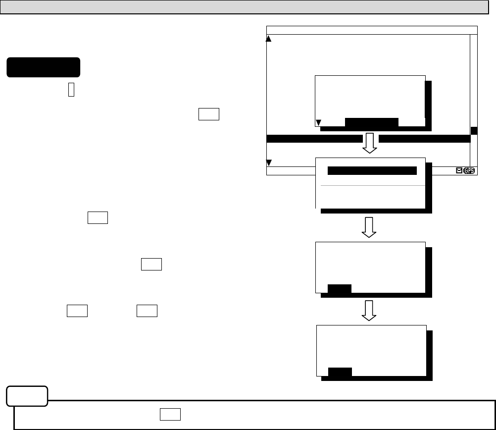
6.2.1 Turning ON the power
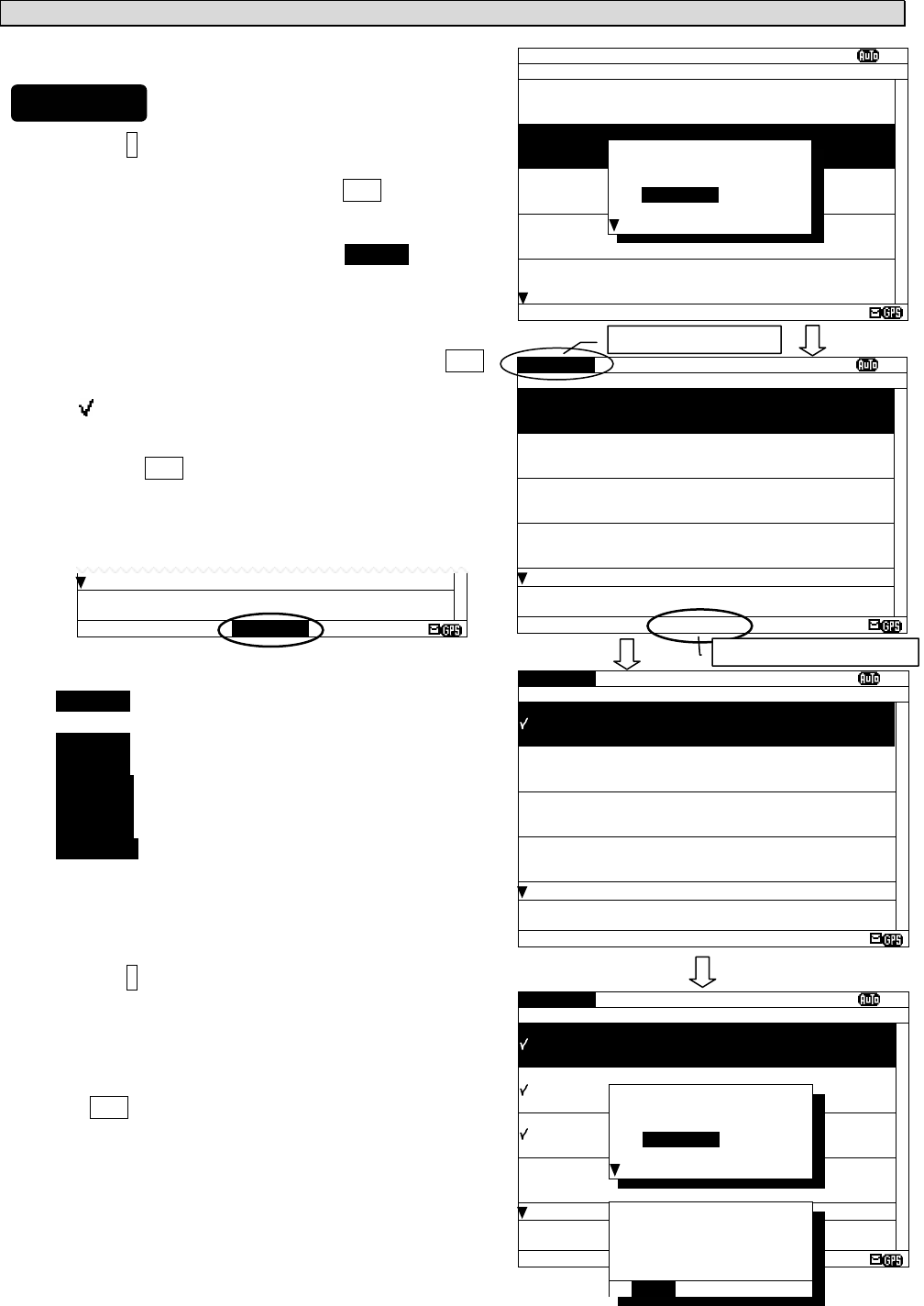
Holding down the PWR/CONT key turns on the power, the starting screen appears, and then the
self-diagnosis screen appears for 15 seconds later. After diagnosis is finished, message text screen appears.
Check the main power supply of a switchboard, and a cable connection of NCR-333 NAVTEX
Receiver when the power cannot be turned on.
Self diagnosis can be canceled when the CLR key is pressed. A message text screen is displayed.
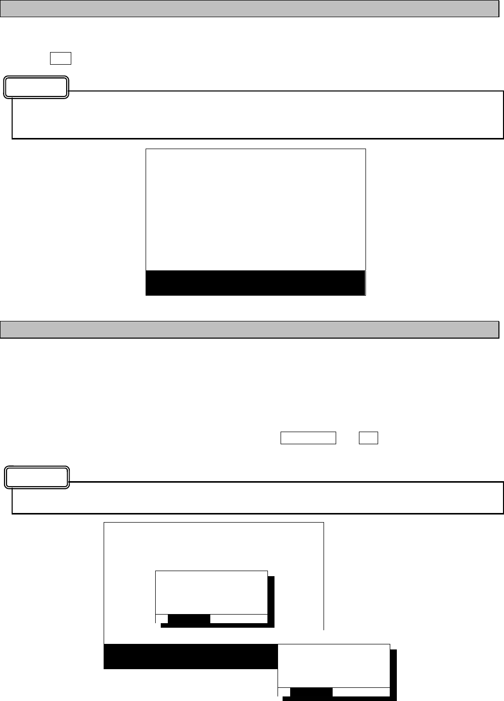
6.2.1.1 Start up (Normal)
When all the results of self-diagnosis are 'OK', the result screen is displayed for about 5 seconds. And then
the result screen changes to the latest message test screen automatically.
* SELF-DIAGNOSING...
ROM CHECK: OK
RAM CHECK: OK
ANT CHECK: OK
LOOP TEST:
- PRESS
‘
CLR
’
KEY TO EXIT -
* NOW LOADING...
NCR-333
NAVTEX RECEIVER
VERSION 1.00
IA01 4209.5 15 04/06/09 12:34
123400 UTC JUNE 04
JAPAN NAVTEX N.W. NR 1260/2004
KEIHIN KO, TOKYO WEST PASSAGE.
DAYTIME DAILY UNTIL 28 JUNE 2004
.
AREA BOUNDED BY
35-35-37.9N 139-47-18.4E
35-34-58.9N 139-48-08.6E
35-34-53.9N 139-48-03.1E
35-35-02.0N 139-47-55.3E
35-35-32.3N 139-47-16.6E
35-35-35.0N 139-47-15.1E
35-33-37.9N 139-46-18.4E
35-33-58.9N 139-46-16.6E
35-33-32.3N 139-45-16.6E
35-35-35.0N 139-44-15.1E, WGS-84
LINE: 10/ 18
Starting screen Self-diagnosis screen
The latest message text screen
Caution
Note
* SELF-DIAGNOSING...
ROM CHECK: OK
RAM CHECK: OK
ANT CHECK: OK
LOOP TEST:
- PRESS
‘
CLR
’
KEY TO EXIT -
Self-diagnosis screen
5 sec.
later
6-3
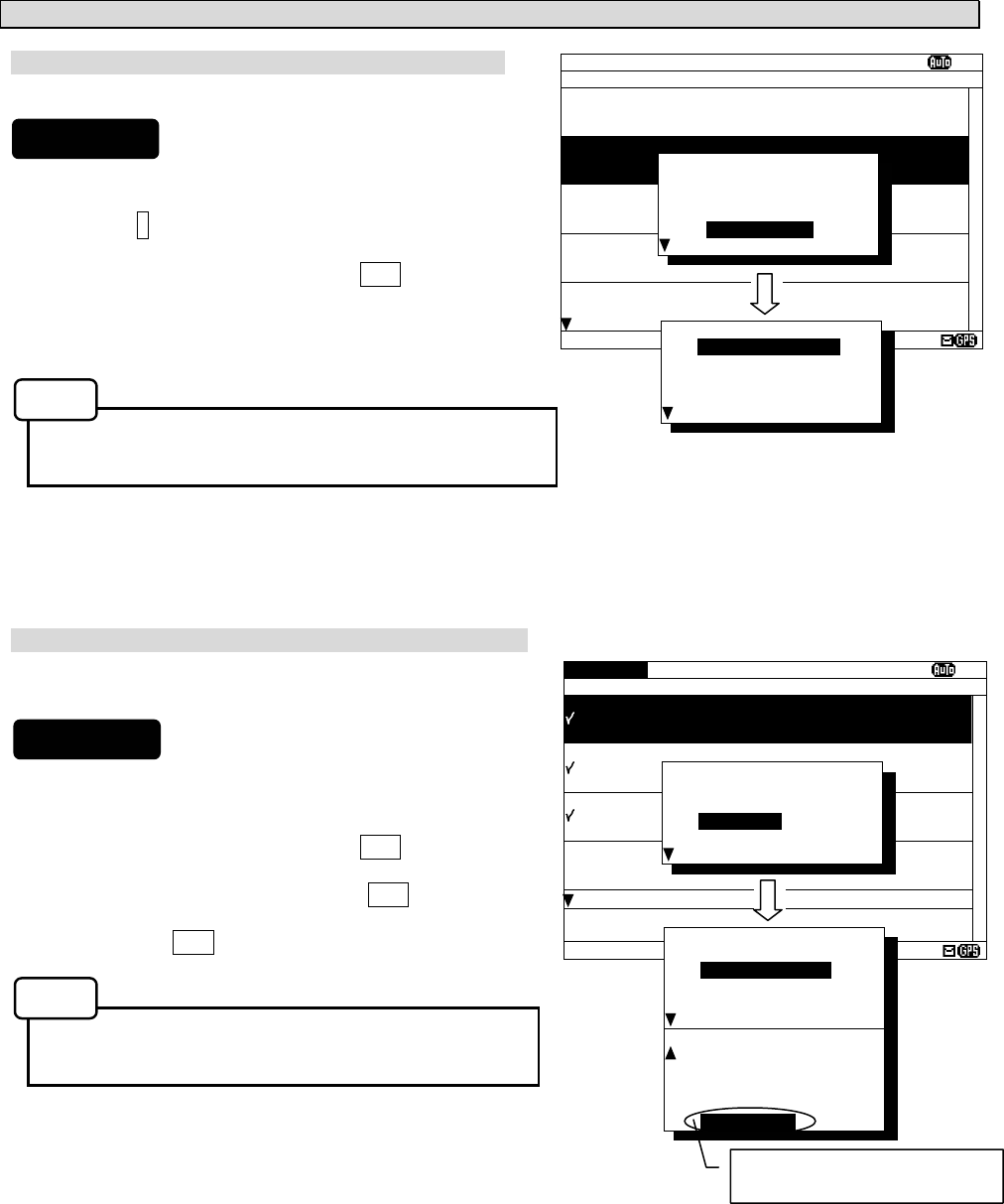
6.2.1.2 Start up (Abnormal-1)
When any result of self-diagnosis is “NG”, a message text screen does not change automatically. And the
caution sentence as shown in the following figure is displayed on the self-diagnostic screen. In this case,
press the CLR key. The latest message text screen appears.
When “NG” is in a result, be sure to carry out self diagnosis in the “MAIN MENU” after displaying the
message text screen. Check the detailed result of the “NG” item. (Refer to “6.3.5.1 Self diagnosis”)
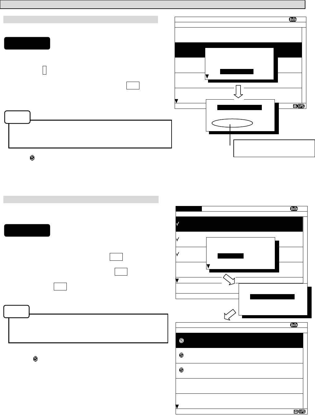
6.2.1.3 Start up (Abnormal-2)
When the result of “ROM CHECK” is “NG”, the sub screen may be displayed as shown in the following
figure.
Be sure to select "[START]" on the sub screen. In this case, although NCR-333 operates, the screen cannot
display in languages other than English.
[START]: The latest message text screen is displayed.
[INST]: The software installation screen is displayed.
When the installation screen is displayed, press and hold the PWR/CONT and DIM keys simultaneously until
the power is turned off. Turn on the power, and restart the NCR-333.
Contact our service center or agents.
* SELF-DIAGNOSING...
ROM CHECK: OK
RAM CHECK: OK
ANT CHECK: OK
LOOP TEST: NG
PLEASE CARRY OUT
‘
SELF-DIAGNOSIS
’
IN MAINTENANCE MENU.
[PRESS
‘
CLR
’
KEY]
* SELF-DIAGNOSING...
ROM CHECK: NG
RAM CHECK: OK
ANT CHECK: OK
LOOP TEST: OK
PLEASE CARRY OUT
‘
SELF-DIAGNOSIS
’
IN MAINTENANCE MENU.
[PRESS
‘
CLR
’
KEY]
*OPTION DAT.ERR*
STARTING NAVTEX?
OR
RE-INSTALL
[START] [INST]
[Option language data error]
*LANGUAGE DAT.ERR*
STARTING NAVTEX?
OR
RE-INSTALL
[START] [INST]
Caution
Caution
6-4
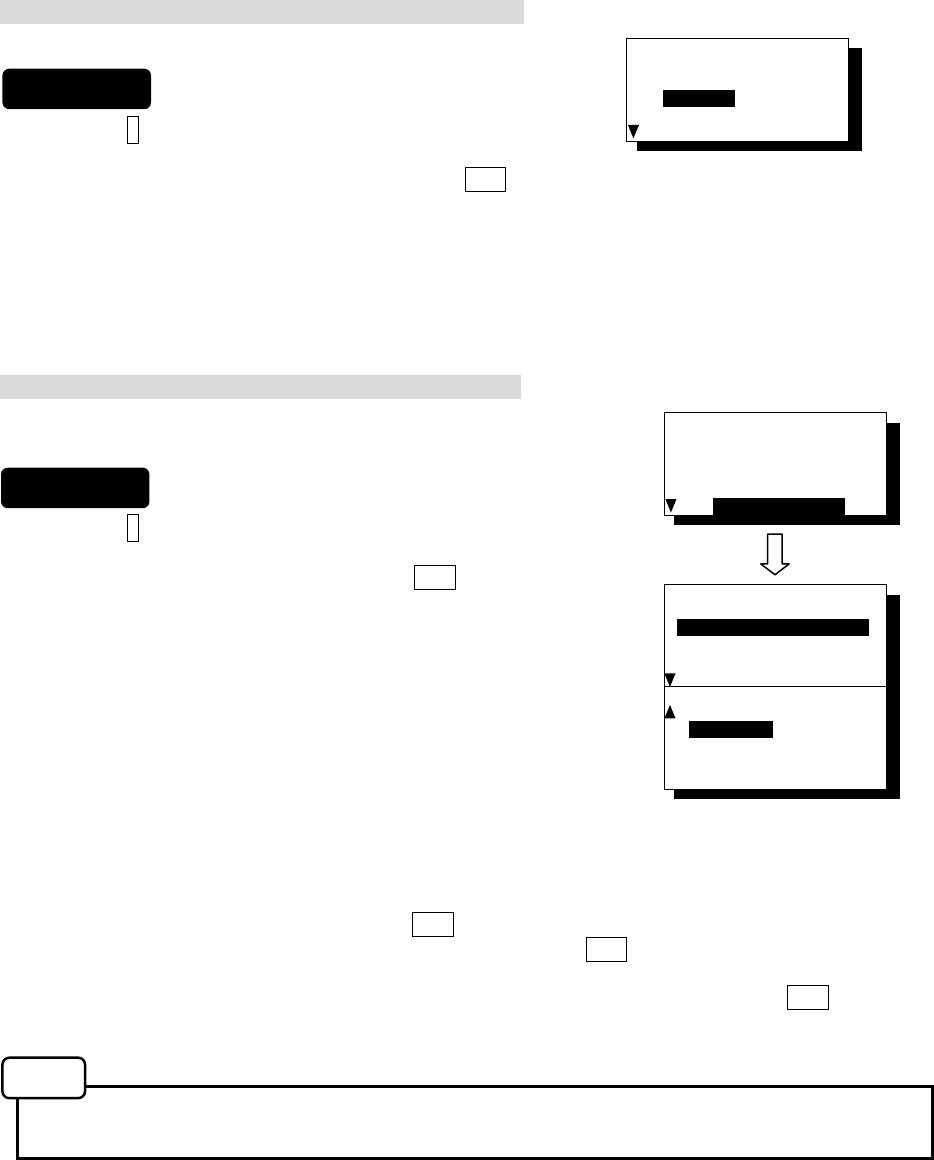
6.2.1.4 Start up (Abnorma-3)
When the following screen is displayed, press and hold the PWR/CONT and DIM keys simultaneously until
the power is turned off.
Contact our service center or agents.
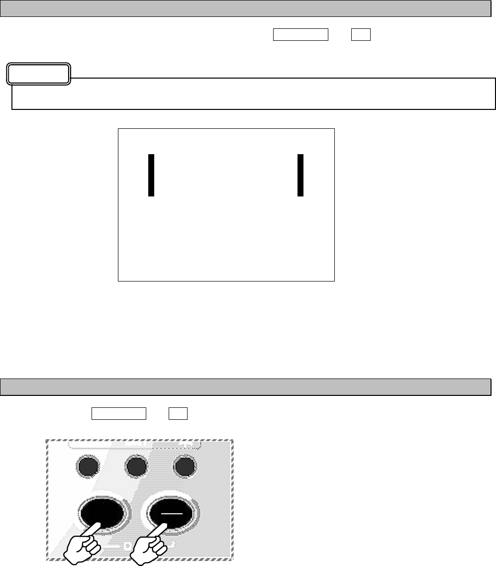
6.2.2 Turning OFF the power
Press and hold the PWR/CONT and DIM keys simultaneously for one second until the power is turned off.
_ CHECK SUM _
_ COMPARING ERROR ! _
_ _
_ PLEASE RE-INSTALL _
_ THE PROGRAM. _
PLEASE RESTART AFTER
SOFTWARE UPDATE
PRESS AND HOLD [DIM]+[PWR]
Caution
DIM PWR
CONT
6-5
6.2.3 Backlight adjustment
Brightness of display can be adjusted in 4 levels.
The display is medium-intensity brightness at starting.
To change the britness, press the DIM key.
Maximum -> Medium -> Minimum -> Turn off the light -> Maximum ->...
The brightness becomes the brightest in the following case;
- Failure alarm is occurred. (“NAVTEX ALARM” screen appears.)
- After reception of “Navigational warnings” message (Message type “A”)
- After reception of “Meteorological warnings” message (Message type “B”))
- After reception of “Search and rescue information, and pirate attack warnings” (Message type
“D”)
- After reception of “Navigational warnings (Additional to letter “A”)” message (Message type “L”)
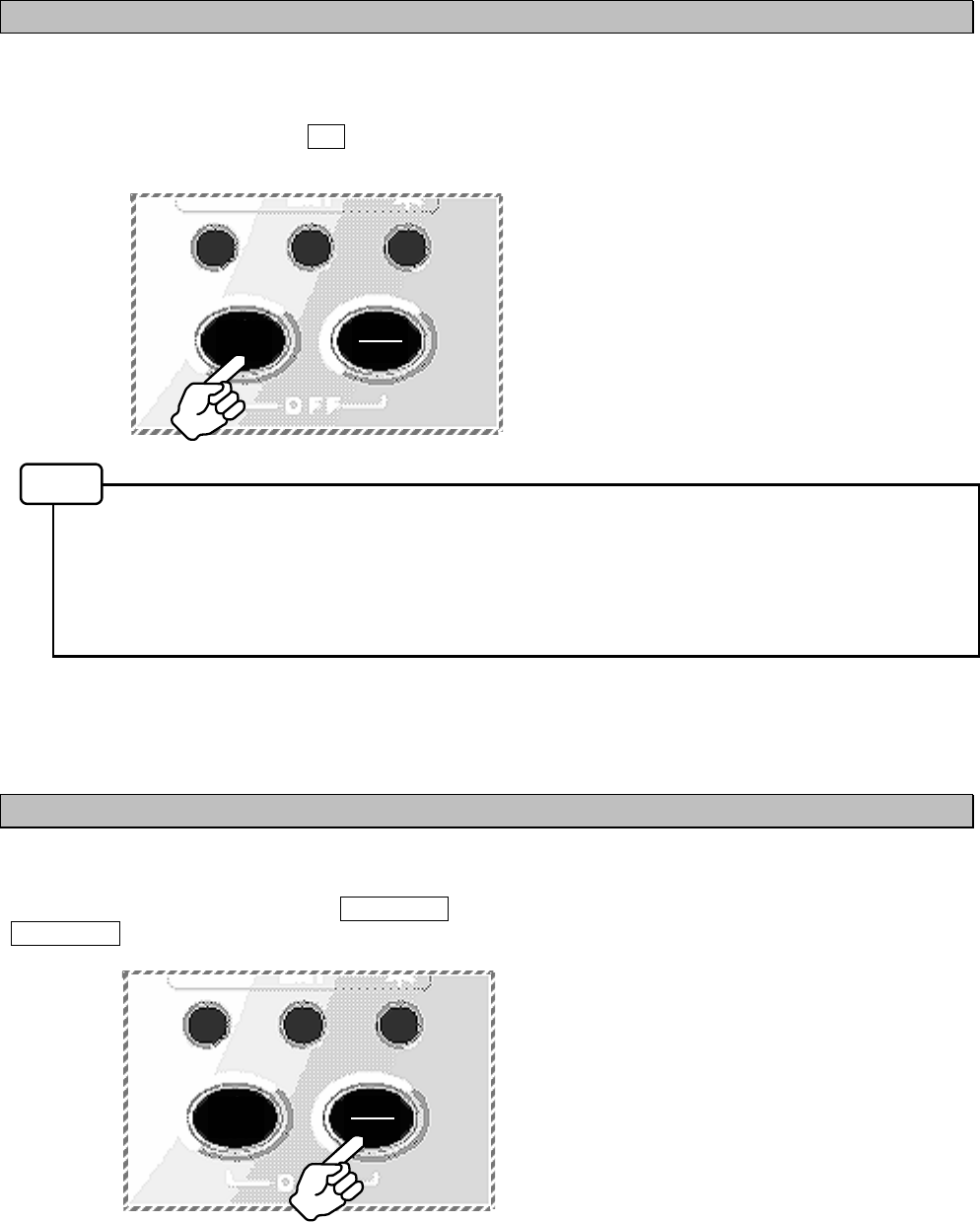
6.2.4 Contrast adjustment
Contrast of view area can be adjusted in 13 levels.
To change the contrast, press the PWR/CONT key. Contrast of View area is changed each time the
PWR/CONT key is pressed.
Notes
DIM PWR
CONT
DIM PWR
CONT
6-6
6.2.5 Alarm
To stop the buzzer sound, press the CLR key. Similarly, to stop the external buzzer sound (option:
CGC-300A), press the CLR key.
An alarm buzzer beeps in the following case;
- Failure alarm is occurred. (“NAVTEX ALARM” screen appears.)
- After reception of “Search and rescue information, and pirate attack warnings” (Message type “D”)
- After reception of “Navigational warnings” message (Message type “A”)
- After reception of “Meteorological warnings” message (Message type “B”))
- After reception of “Navigational warnings (Additional to letter “A”)” message (Message type “L”)
- After reception of other messages
Refer to “6.3.3.3 Buzzer settings” for a setup of alarm buzzer.
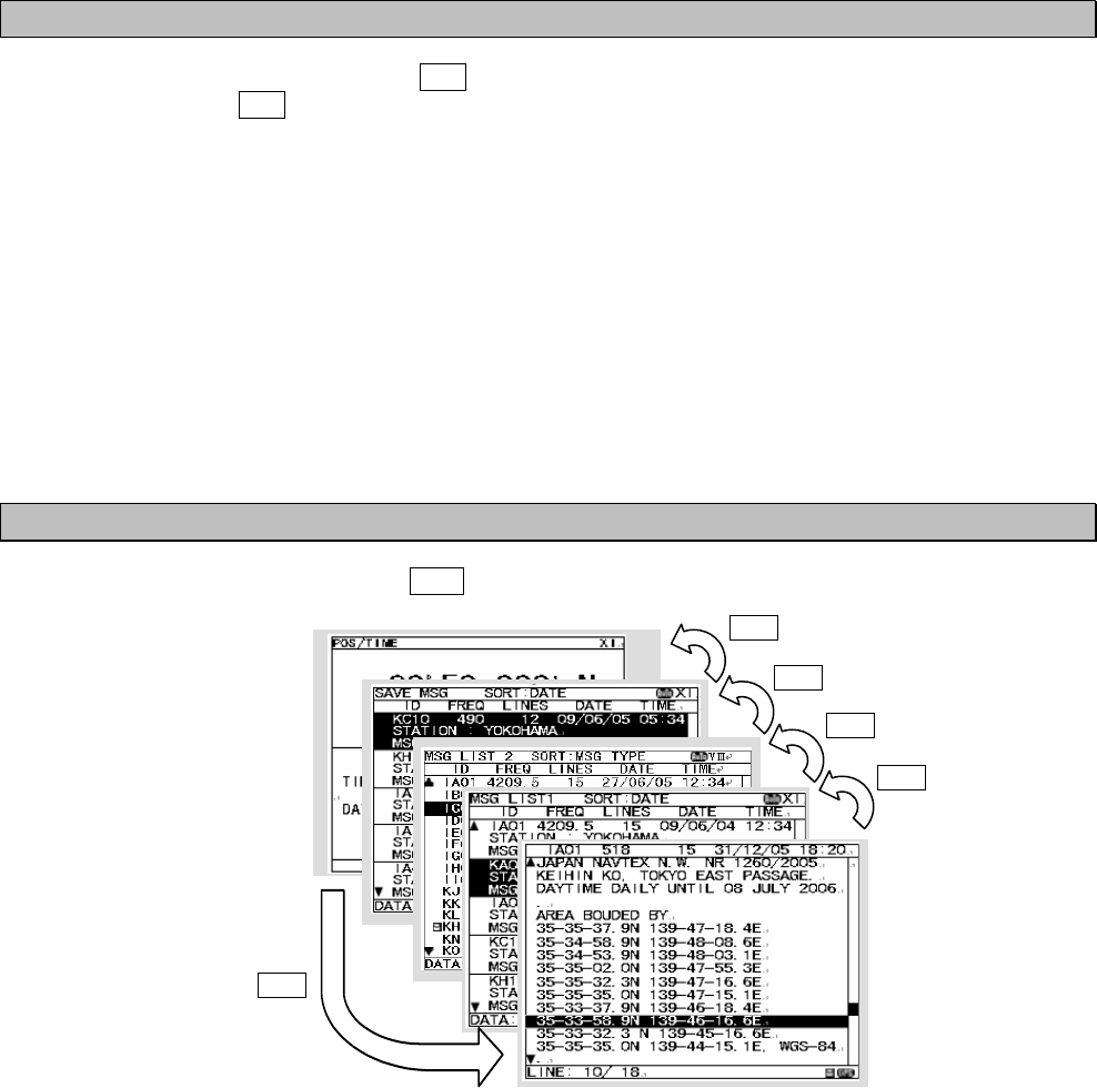
6.2.6 Screen switching
To change the display screen, press the DISP key.
DISP
DISP
DISP
DISP
DISP
6-7
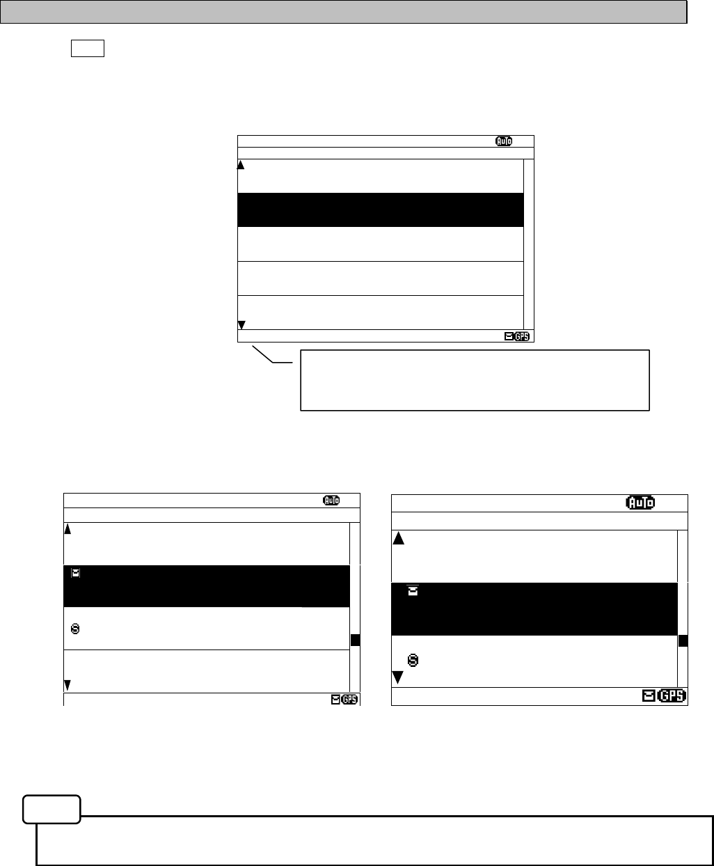
6.2.7 Displaying the message
6.2.7.1 Message text
After starting this equipment, the latest message text screen is displayed.
Additionally, the latest message text screen is displayed just after reception of message while opening any
screen.
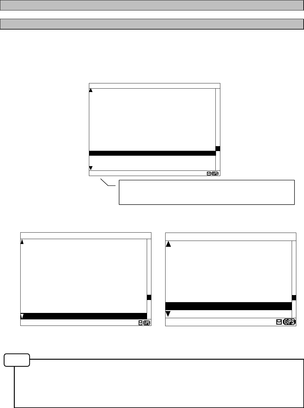
The number of lines of the message text screen is changed as follows;
- Character size “Normal”: The message text of 16 lines is displayed at the maximum.
- Character size “Medium”: The message text of 13 lines
- Character size “Large”: The message text of 10 lines
Refer to “6.3.4.1 Character size setting” about change of character size.
Fig.6-1 Message text screen
IA01 4209.5 18 31/12/05 18:20
JAPAN NAVTEX N.W. NR 1260/2005
KEIHIN KO, TOKYO EAST PASSAGE.
DAYTIME DAILY UNTIL 08 JULY 2006
.
AREA BOUDED BY
35-35-37.9N 139-47-18.4E
35-34-58.9N 139-48-08.6E
35-34-53.9N 139-48-03.1E
35-35-02.0N 139-47-55.3E
35-35-32.3N 139-47-16.6E
35-35-35.0N 139-47-15.1E
35-33-37.9N 139-46-18.4E
35-33-58.9N 139-46-16.6E
LINE: 13/ 18
IA01 4.2 31/12/05
JAPAN NAVTEX N.W.
NR 1260/2005
KEIHIN KO, TOKYO
EAST PASSAGE.
DAYTIME DAILY
UNTIL 08 JULY 2006
.
AREA BOUDED BY
35-35-37.9N 139-47
-18.4E
L: 9/ 18
(Character size: Medium) (Character size: Large)
(Character size: Normal)
Notes
The number on the left side of DATA shows the line number of
the present cursor position. The right side number shows the
total number of lines.
IA01 518 15 31/12/05 18:20
JAPAN NAVTEX N.W. NR 1260/2005
KEIHIN KO, TOKYO EAST PASSAGE.
DAYTIME DAILY UNTIL 08 JULY 2006
.
AREA BOUDED BY
35-35-37.9N 139-47-18.4E
35-34-58.9N 139-48-08.6E
35-34-53.9N 139-48-03.1E
35-35-02.0N 139-47-55.3E
35-35-32.3N 139-47-16.6E
35-35-35.0N 139-47-15.1E
35-33-37.9N 139-46-18.4E
35-33-58.9N 139-46-16.6E
35-33-32.3 N 139-45-16.6E
35-35-35.0N 139-44-15.1E, WGS-84
.
LINE: 10/ 18
6-8
The message type and the message identification codes are as follows.
The message identification codes displayed on upper-left side of the message text screen (“lA01” in the
above example) indicates the message type.
These codes consist of four alpha-numeric characters which denote the coast station originating the
message, the message type and the report number.
a. First character
The coast station that has transmitted the message is assigned by a character from A to Z.
b. Second character
This charactger identifies the type of message.
[A] Navigational warnings
[B] Meteorological warnings
[C] Ice reports
[D] Search and rescue information, and pirate attack warnings
[E] Meteorological forecasts
[F] Pilot service messages
[G] AIS
[H] LORAN-C messages
[J] SATNAV messages
[K] Other electronic navaid messages
[L] Navigational warnings (Additional to letter “A”)
[V - Y] Special services
[Z] QRU (No messages on hand)
c. Third and fourth characters
These characters denote the report number assigned to the message by the coast station where the
message originated.
The four-character identification code is stored in memory only when the message is received at a
character error rate (CER) of 33 % or less. When an incoming message has the same identification code
as one already stored message at CER of 4 % or less in memory (about 70 hours), it will not be displayed
and stored. The above, however, does not apply to report number ‘00’. For report number ‘00’, the
code is not held in memory and messages are displayed and stored each time they are received.
a. Clear the unread mark
The message text is displayed after the message has been received.
Unread mark on the status bar shows unread messages has been received.
1) If the ENT key is pressed, the caution sentence
disappears, and this message changes to read
message. If all messages are read messages, the “ ”
mark of status bar is cleared.
- Unread messages can also be checked on the
message list 1 or 2.
(Refer to “6.2.7.2” or “6.2.7.3”)
Be sure to clear the unread mark after reading a
message.
Procedures
Notes
IA01 518 15 31/12/05 18:20
JAPAN NAVTEX N.W. NR 1260/2005
KEIHIN KO, TOKYO EAST PASSAGE.
DAYTIME DAILY UNTIL 08 JULY 2006
.
AREA BOUDED BY
35-35-37.9N 139-47-18.4E
35-34-58.9N 139-48-08.6E
35-34-53.9N 139-48-03.1E
35-35-02.0N 139-47-55.3E
35-35-32.3N 139-47-16.6E
35-35-35.0N 139-47-15.1E
35-33-37.9N 139-46-18.4E
35-33-58.9N 139-46-16.6E
35-33-32.3 N 139-45-16.6E
35-35-35.0N 139-44-15.1E, WGS-84
THE MSG WAS RECEIVED. PRESS[ENT]KEY
LINE: 10/ 18
Unread mark
Caution sentence
6-9
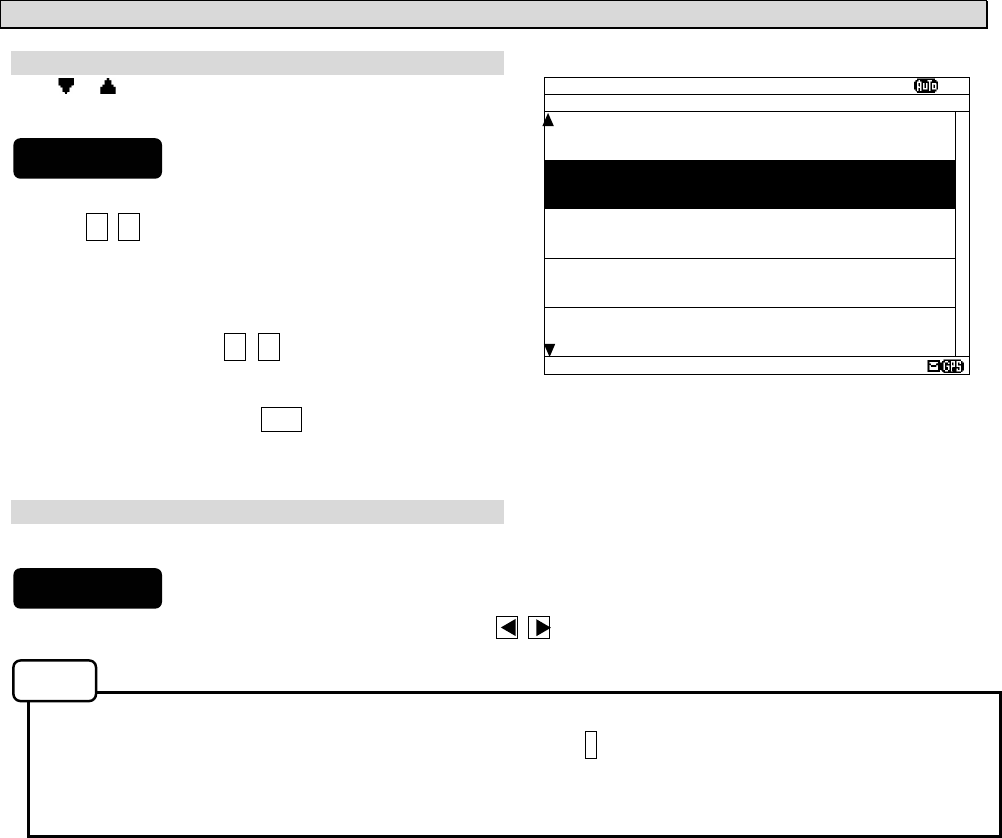
b. Read the message
Screen scrolling 1
The ‘ ‘ (‘ ‘) mark is displayed when the message text
scroll downward (upward) is available.
1) To move the cursor up/down to the next line, press
the ▲ ▼ key. (Cursor scrolls one by one in the
message text.)
2) To scroll the next page of the message text
downward (upward) when cursor is on the bottom
(top) line, press the ▼ (▲) key.
Screen scrolling 2
To skip to the next / previous message text screen is available.
1) To display to the previous / next screen, press the key.
c. Read the other message
Read the new message
The new message can be displayed on the message
text screen.
1) Press the * key. The sub screen appears.
2) Select the “[NEXT MSG]”, and press the ENT key.
3) The new message is displayed.
- “[NEXT MSG]” can be selected when there is new message.
Read the old message
The old message can be displayed on the message text screen.
1) Press the * key. The sub screen appears.
2) Select the “[PREV. MSG]”, and press the ENT key.
3) The old message is displayed.
- “[PREV.MSG]” can be selected when there is old message.
IA01 518 15 31/12/05 18:20
JAPAN NAVTEX N.W. NR 1260/2005
KEIHIN KO, TOKYO EAST PASSAGE.
DAYTIME DAILY UNTIL 08 JULY 2006
.
AREA BOUDED BY
35-35-37.9N 139-47-18.4E
35-34-58.9N 139-48-08.6E
35-34-53.9N 139-48-03.1E
35-35-02.0N 139-47-55.3E
35-35-32.3N 139-47-16.6E
35-35-35.0N 139-47-15.1E
35-33-37.9N 139-46-18.4E
35-33-58.9N 139-46-16.6E
35-33-32.3 N 139-45-16.6E
35-35-35.0N 139-44-15.1E, WGS-84
.
LINE: 10/ 18
* SET UP *
[NEXT MSG]
[PREV. MSG]
[SAVE MSG]
[PRINT OUT]
DATA OUT
Procedures
Procedures
Procedures
Notes
Notes
Procedures
6-10
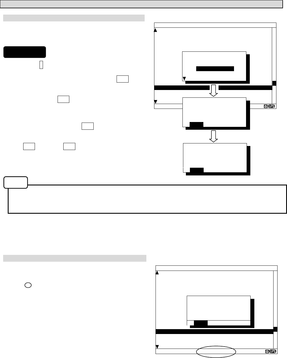
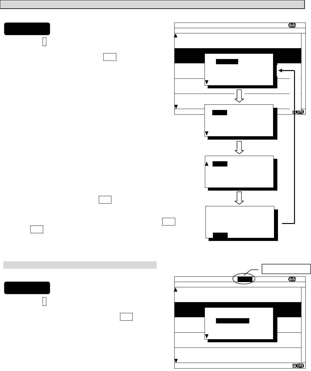
d. Save the message
Save the message
The currently open message can be saved.
The saved message is permanently stored in the data
memory.
1) Press the * key. The sub screen appears.
2) Select the “[SAVE MSG]”, and press the ENT key.
3) “ARE YOU SURE?” is displayed. Select the “[OK]”,
and press the ENT key. (“NOW SAVING...” is
displayes on the sub screen.)
To return to the sub screen (SET UP), select
“[CANCEL]” and press the ENT key.
4) After message saving has been completed, press
the ENT key or the CLR key.
- The message that is not saved (the stored message) is automatically erased from the data memory
about 70 hours after receiving.
- 50 messages of an average length of 500 characters can be saved in each channel.
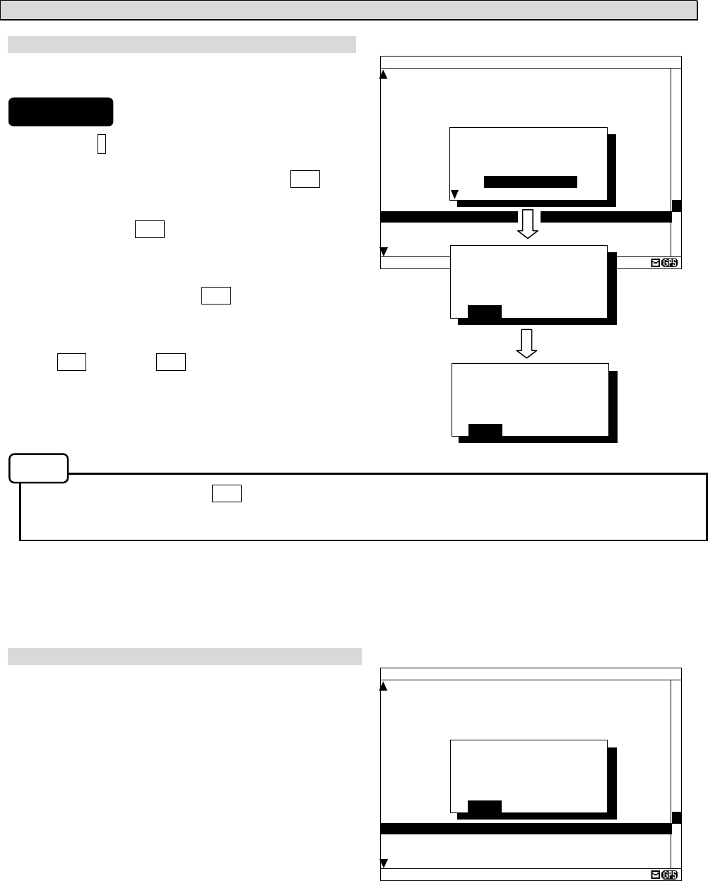
The message cannot be saved
When the saved message in the data memory is full, the
sub screen is displayed as shown in the following figure,
and the status bar shows which channel cannot be
saved ( mark).
Refer to “c. Put a check mark” (6.2.7.2 Message list 1)
for explanation of the display of the status bar.
Save again after deleting the message in save message
list when unable to save a message.
IA01 518 15 31/12/05 18:20
JAPAN NAVTEX N.W. NR 1260/2005
KEIHIN KO, TOKYO EAST PASSAGE.
DAYTIME DAILY UNTIL 08 JULY 2006
.
AREA BOUDED BY
35-35-37.9N 139-47-18.4E
35-34-58.9N 139-48-08.6E
35-34-53.9N 139-48-03.1E
35-35-02.0N 139-47-55.3E
35-35-32.3N 139-47-16.6E
35-35-35.0N 139-47-15.1E
35-33-37.9N 139-46-18.4E
35-33-58.9N 139-46-16.6E
35-33-32.3 N 139-45-16.6E
35-35-35.0N 139-44-15.1E, WGS-84
.
LINE: 10/ 18 RX1--OV
*SAVE MSG*
TO ADD A NEW MSG,
DELETE A MSG
IN THE SAVE LIST.
[OK]
IA01 518 15 31/12/05 18:20
JAPAN NAVTEX N.W. NR 1260/2005
KEIHIN KO, TOKYO EAST PASSAGE.
DAYTIME DAILY UNTIL 08 JULY 2006
.
AREA BOUDED BY
35-35-37.9N 139-47-18.4E
35-34-58.9N 139-48-08.6E
35-34-53.9N 139-48-03.1E
35-35-02.0N 139-47-55.3E
35-35-32.3N 139-47-16.6E
35-35-35.0N 139-47-15.1E
35-33-37.9N 139-46-18.4E
35-33-58.9N 139-46-16.6E
35-33-32.3 N 139-45-16.6E
35-35-35.0N 139-44-15.1E, WGS-84
.
LINE: 10/ 18
* SET UP *
[NEXT MSG]
[PREV. MSG]
[SAVE MSG]
[PRINT OUT]
DATA OUT
*SAVE MSG*
SAVE OK
[OK] [CANCEL]
*SAVE MSG*
ARE YOU SURE?
[OK] [CANCEL]
Procedures
Notes
6-11
e. Print the message
Print the message
The currently open message can be printed when
having connected the external printer.
1) Press the * key. The sub screen appears.
2) Select the “[PRINT OUT]”, and press the ENT key.
3) “ARE YOU SURE?” is displayed. Select the “[OK]”,
and press the ENT key. (“NOW PRINTING...” is
displayed on the sub screen.)
To return to the sub screen (SET UP), select
“[CANCEL]” and press the ENT key.
4) After message printing has been completed, press
the ENT key or the CLR key.
- To stop printing, press the CLR key while printing.
- "[PRINT OUT]" cannot be selected when "DATA OUT" of "PRINTER PROPERTY" has set up "OFF".
Refer to “6.3.4.5 External printer settings”.
The message cannot be printed
When printing is unable, the sub screen is displayed as
shown in the following figure.
In this case, check the followings;
- The connection between the external printer
and NCR-333.
- “PRINTER PROPERTY” settings. (Refer
to “6.3.4.5 External printer settings”)
- Confirm the external printer. (Paper out, etc...)
IA01 518 15 31/12/05 18:20
JAPAN NAVTEX N.W. NR 1260/2005
KEIHIN KO, TOKYO EAST PASSAGE.
DAYTIME DAILY UNTIL 08 JULY 2006
.
AREA BOUDED BY
35-35-37.9N 139-47-18.4E
35-34-58.9N 139-48-08.6E
35-34-53.9N 139-48-03.1E
35-35-02.0N 139-47-55.3E
35-35-32.3N 139-47-16.6E
35-35-35.0N 139-47-15.1E
35-33-37.9N 139-46-18.4E
35-33-58.9N 139-46-16.6E
35-33-32.3 N 139-45-16.6E
35-35-35.0N 139-44-15.1E, WGS-84
.
LINE: 10/ 18
* PRINTER ERROR *
PLEASE CHECK THE
“
PRINTER
PROPERTY
”
SETTING.
[OK]
IA01 518 15 31/12/05 18:20
JAPAN NAVTEX N.W. NR 1260/2005
KEIHIN KO, TOKYO EAST PASSAGE.
DAYTIME DAILY UNTIL 08 JULY 2006
.
AREA BOUDED BY
35-35-37.9N 139-47-18.4E
35-34-58.9N 139-48-08.6E
35-34-53.9N 139-48-03.1E
35-35-02.0N 139-47-55.3E
35-35-32.3N 139-47-16.6E
35-35-35.0N 139-47-15.1E
35-33-37.9N 139-46-18.4E
35-33-58.9N 139-46-16.6E
35-33-32.3 N 139-45-16.6E
35-35-35.0N 139-44-15.1E, WGS-84
.
LINE: 10/ 18
* SET UP *
[NEXT MSG]
[PREV. MSG]
[SAVE MSG]
[PRINT OUT]
DATA OUT
*PRINT OUT*
ARE YOU SURE?
[OK] [CANCEL]
*PRINT OUT*
PRINT OUT OK
[OK] [CANCEL]
Procedures
Notes
6-12
f. Output the message from an external port
The data of currently open message text can be output
with connection the external equipment (ECDIS, MPD).
1) Press the * key. The sub screen appears.
2) Select the “[DATA OUT]”, and press the ENT key.
3) Select the port which outputs message data.
- SEL-DATA OUT: The message data is outputted
from a "DATA OUT" port.
- SEL- DISP OUT: The message data is outputted
from a "DISP" port.
4) “ARE YOU SURE?” is displayed. Select the “[OK]”,
and press the ENT key. (“NOW OUTPUTTING...” is
displayed on the sub screen.)
To return to the sub screen (SET UP), select
“[CANCEL]” and press the ENT key.
5) After message outputting has been completed,
press the ENT key or the CLR key.
- To stop outputting, press the CLR key while outputting.
IA01 518 15 31/12/05 18:20
JAPAN NAVTEX N.W. NR 1260/2005
KEIHIN KO, TOKYO EAST PASSAGE.
DAYTIME DAILY UNTIL 08 JULY 2006
.
AREA BOUDED BY
35-35-37.9N 139-47-18.4E
35-34-58.9N 139-48-08.6E
35-34-53.9N 139-48-03.1E
35-35-02.0N 139-47-55.3E
35-35-32.3N 139-47-16.6E
35-35-35.0N 139-47-15.1E
35-33-37.9N 139-46-18.4E
35-33-58.9N 139-46-16.6E
35-33-32.3 N 139-45-16.6E
35-35-35.0N 139-44-15.1E, WGS-84
.
LINE: 10/ 18
* SET UP *
[NEXT MSG]
[PREV. MSG]
[SAVE MSG]
[PRINT OUT]
DATA OUT
*DATA OUT*
ARE YOU SURE?
[OK] [CANCEL]
*DATA OUT*
DATA OUT OK
[OK] [CANCEL]
*DATA OUT*
[SEL-ECDIS OUT]
[SEL-DISP OUT]
[CANCEL]
Procedures
Notes
6-13
6.2.7.2 Message list 1
Press the DISP key several times. The list of the currently stored messages appears.
This list shows a receiving station and a message type for each message.
- "LINES" and "TIME" are not displayed when character size has selected "LARGE".
(Same applies to the message list 2 and a save message list)
Fig.6-2 Message list 1
(Character size: Medium) (Character size: Large)
(Character size: Normal)
MSG LIST1 SORT:DATE
Ⅵ
ID FREQ LINES DATE TIME
IA01 4209.5 15 28/12/05 12:34
STATION : YOKOHAMA
MSG TYPE: NAVIGATIONAL WARNINGS
KA04 518 10 28/12/05 12:33
STATION : KOSHIRO
MSG TYPE: NAVIGATIONAL WARNINGS
IA07 490 20 28/12/05 12:32
STATION : YOKOHAMA
MSG TYPE: NAVIGATIONAL WARNINGS
KC10 490 12 27/12/05 18:30
STATION : KUSHIRO
MSG TYPE: ICE REPORTS
DATA:321/429
MSG LIST1
Ⅵ
ID FREQ DATE
IA01 4.2 28/12/05
STN:YOKOHAMA
MT :NAV WARNINGS
KA04 518 28/12/05
STN:KUSHIRO
MT :NAV WARNINGS
IA07 490 28/12/05
STN:YOKOHAMA
MT :NAV WARNINGS
D:321/429
Notes
MSG LIST1 SORT:DATE XI
ID FREQ LINES DATE TIME
IA01 4209.5 15 09/06/04 12:34
STATION : YOKOHAMA
MSG TYPE: NAVIGATIONAL WARNINGS
KA04 518 10 09/06/04 10:34
STATION : KUSIRO
MSG TYPE: NAVIGATIONAL WARNINGS
IA07 490 20 04/06/09 09:34
STATION : YOKOHAMA
MSG TYPE: NAVIGATIONAL WARNINGS
KC10 490 12 04/06/09 05:34
STATION : YOKOHAMA
MSG TYPE: ICE REPORTS
KH13 518 5 09/06/04 05:34
STATION : KUSIRO
MSG TYPE: LORAN MESSAGE
DATA:329/438
The number on the left side of DATA shows the
message number of the present cursor position. The
right side number shows the total number of messages.
6-14
a. Select a message
Screen scrolling 1
The ‘ ‘ (‘ ‘) mark is displayed when the message list 1
scroll downward (upward) is available.
1) To meve the cursor up/down to the next line, press
the ▲ ▼ key. (Cursor scrolls one by one in the
message list 1.)
2) To scroll the next page of the message List 1
downward (upward) when cursor is on the bottom
(top) line, press the ▼ (▲) key.
3) To read a message text, move the cursor to the
message and press the ENT key.
Screen scrolling 2
To skip to the next / previous message text screen is available.
1) To display to the previous / next screen, press the key.
Selecting "[PGUP]"or "[PGDN]" of the sub screen can also scroll the message list 1 screen similarly to
the above procedures. To display the sub screen, press the * key.
- [PGDN]: Previous screen
- [PGUP]: Next screen
MSG LIST1 SORT:DATE XI
ID FREQ LINES DATE TIME
IA01 4209.5 15 09/06/04 12:34
STATION : YOKOHAMA
MSG TYPE: NAVIGATIONAL WARNINGS
KA04 518 10 09/06/04 10:34
STATION : KUSIRO
MSG TYPE: NAVIGATIONAL WARNINGS
IA07 490 20 04/06/09 09:34
STATION : YOKOHAMA
MSG TYPE: NAVIGATIONAL WARNINGS
KC10 490 12 04/06/09 05:34
STATION : YOKOHAMA
MSG TYPE: ICE REPORTS
KH13 518 5 09/06/04 05:34
STATION : KUSIRO
MSG TYPE: LORAN MESSAGE
DATA:329/438
Procedures
Procedures
Notes
6-15
b. Sort messages
To search message quickly, messages can be sorted.
1) Press the * key. The sub screen appears.
2) Select the “LIST”, and press the ENT key.
The items of “LIST” appear.
3) The items of “LIST” are as follows;
SORT: The stored messages are displayed
- DATE: in the order of the date received in reverse
- STNS: in the order from the receiving station "A"
- AREA: in the order from the NAVAREA “I”
- MSGTYP: in the order from the message type “A”
- UNREAD: in the order of the date received in reverse
(unread messages)
DISP: The messages displayed on the selected channel.
- ALL: All the messages are displayed.
- 518KHZ: Only 518 kHz messages are displayed.
- 490KHZ: Only 490 kHz messages are displayed.
- 4209.5KHZ: Only 4209.5 kHz messages are displayed.
4) Select "SORT" item, and then select “DISP” item.
5) Select the [OK], and press the ENT key.
Sorting message starts.
6) After message sorting has been completed, press the ENT key
or the CLR key.
Rearrange the order of message conversely
1) Press the * key. The sub screen appears.
2) Select the “REVERSE”, and press the ENT key.
3) The order of the message currently displayed is
rearranged conversely, and title of ‘SORT’ is
highlighted.
MSG LIST1 SORT:DATE XI
ID FREQ LINES DATE TIME
IA01 4209.5 15 09/06/04 12:34
STATION : YOKOHAMA
MSG TYPE: NAVIGATIONAL WARNINGS
KA04 518 10 09/06/04 10:34
STATION : KUSIRO
MSG TYPE: NAVIGATIONAL WARNINGS
IA07 490 20 04/06/09 09:34
STATION : YOKOHAMA
MSG TYPE: NAVIGATIONAL WARNINGS
KC10 490 12 04/06/09 05:34
STATION : YOKOHAMA
MSG TYPE: ICE REPORTS
KH13 518 5 09/06/04 05:34
STATION : KUSIRO
MSG TYPE: LORAN MESSAGE
DATA:329/438
*SET UP*
LIST_
[REVERSE]
[CHECK]
SAVE MENU
PRINT MENU
*LIST*
SORT:[DATE]
STNS
AREA
MSGTYP
UNREAD
*LIST*
DISP:[ALL]
518KHZ
490KHZ
4209.5KHZ
[OK] [CANCEL]
NOW SETTING...
[OK] [CANCEL]
MSG LIST1 SORT:DATE XI
ID FREQ LINES DATE TIME
IB21 4209.5 15 12/05/05 11:10
STATION : YOKOHAMA
MSG TYPE: NAVIGATIONAL WARNINGS
IA33 518 10 13/05/05 22:34
STATION : KUSIRO
MSG TYPE: NAVIGATIONAL WARNINGS
KA67 490 20 04/06/09 02:15
STATION : YOKOHAMA
MSG TYPE: NAVIGATIONAL WARNINGS
PC01 490 12 04/06/09 10:25
STATION : YOKOHAMA
MSG TYPE: ICE REPORTS
IA01 4209.5 15 09/06/04 12:34
STATION : KUSIRO
MSG TYPE: LORAN MESSAGE
DATA:329/438
*SET UP*
LIST
[REVERSE]
[CHECK]
SAVE MENU
PRINT MENU
Highlight a title
Procedures
Procedures
6-16
c. Put a check mark (Save/print/output more than one message at the same time)
Each checked message can be saved (printed or output)
at the same time.
1) Press the * key. The sub screen appears.
2) Select the “[CHECK]”, and press the ENT key.
The sub screen is closed, and the message list 1
changes to the check screen.
The check screen highlights the "CHECK" on the
display title.
The number of check marks is displayed on the status
line.
3) Select the message for checking, and press the ENT
key.
The “ “ is displayed on a line with cursor.
This mark means having checked the message.
4) Press the ENT key and put a check to other
messages.
In addition, when the following characters are
displayed,
It means that the checked number exceeded the
number which can be saved in the memory.
RX1--OV: The message of RX1 (518kHz) cannot
be saved any more to the memory.
RX2--OV: RX2 (490 kHz)
RX3--OV: RX3 (4209.5 kHz)
RX12-OV: RX1 and RX2
RX13-OV: RX1 and RX3
RX23-OV: RX2 and RX3
RX123OV: RX1, RX2 and RX3
In this case, messages still can be put a check,
however, the messages cannot be printed or data can
not be output.
5) Press the * key, to display the sub screen.
Select "SAVE MENU", "PRINT MENU", or "PORT
MENU" in the auxiliary screen.
To save, print or output messages at the same time,
refer to the procedure of d), e) and f).
If the CLR key is pressed on the sub screen, “EXIT
WITHOUT SETTING” is displayed in the sub screen. If
"O.K." is selected, the check marks are removed and
the display screen returns to the message list 1
screen.
KH13 518 5 09/06/04 05:34
CHECKING - PRESS [ENT] KEY
FINISHED - PRESS [*] KEY
DATA:329/438 RX1--OV
MSG LIST1 SORT:DATE XI
ID FREQ LINES DATE TIME
IA01 4209.5 15 09/06/04 12:34
STATION : YOKOHAMA
MSG TYPE: NAVIGATIONAL WARNINGS
KA04 518 10 09/06/04 10:34
STATION : KUSIRO
MSG TYPE: NAVIGATIONAL WARNINGS
IA07 490 20 04/06/09 09:34
STATION : YOKOHAMA
MSG TYPE: NAVIGATIONAL WARNINGS
KC10 490 12 04/06/09 05:34
STATION : YOKOHAMA
MSG TYPE: ICE REPORTS
KH13 518 5 09/06/04 05:34
STATION : KUSIRO
MSG TYPE: LORAN MESSAGE
DATA:329/438
*SET UP*
LIST_
[REVERSE]
[CHECK]
SAVE MENU
PRINT MENU
CHECK SORT:DATE XI
ID FREQ LINES DATE TIME
IA01 4209.5 15 09/06/04 12:34
STATION : YOKOHAMA
MSG TYPE: NAVIGATIONAL WARNINGS
KA04 518 10 09/06/04 10:34
STATION : KUSIRO
MSG TYPE: NAVIGATIONAL WARNINGS
IA07 490 20 04/06/09 09:34
STATION : YOKOHAMA
MSG TYPE: NAVIGATIONAL WARNINGS
KC10 490 12 04/06/09 05:34
STATION : YOKOHAMA
MSG TYPE: ICE REPORTS
KH13 518 5 09/06/04 05:34
CHECKING - PRESS [ENT] KEY
FINISHED - PRESS [*] KEY
DATA:329/438 0
CHECK SORT:DATE XI
ID FREQ LINES DATE TIME
IA01 4209.5 15 09/06/04 12:34
STATION : YOKOHAMA
MSG TYPE: NAVIGATIONAL WARNINGS
KA04 518 10 09/06/04 10:34
STATION : KUSIRO
MSG TYPE: NAVIGATIONAL WARNINGS
IA07 490 20 04/06/09 09:34
STATION : YOKOHAMA
MSG TYPE: NAVIGATIONAL WARNINGS
KC10 490 12 04/06/09 05:34
STATION : YOKOHAMA
MSG TYPE: ICE REPORTS
KH13 518 5 09/06/04 05:34
CHECKING - PRESS [ENT] KEY
FINISHED - PRESS [*] KEY
DATA:329/438 1
CHECK SORT:DATE XI
ID FREQ LINES DATE TIME
IA01 4209.5 15 09/06/04 12:34
STATION : YOKOHAMA
MSG TYPE: NAVIGATIONAL WARNINGS
KA04 518 10 09/06/04 10:34
STATION : KUSIRO
MSG TYPE: NAVIGATIONAL WARNINGS
IA07 490 20 04/06/09 09:34
STATION : YOKOHAMA
MSG TYPE: NAVIGATIONAL WARNINGS
KC10 490 12 04/06/09 05:34
STATION : YOKOHAMA
MSG TYPE: ICE REPORTS
KH13 518 5 09/06/04 05:34
CHECKING - PRESS [ENT] KEY
FINISHED - PRESS [*] KEY
DATA:329/438 3
*SET UP*
LIST
[REVERSE]
[CHECK]
SAVE MENU
PRINT MENU
Number of check marks
Check screen
*SET UP*
EXIT WITHOUT
SETTING.
ARE YOU SURE?
[OK] [CANCEL]
Procedures
6-17
d. Save messages
Save one message
The selected message can be saved.
1) Move cursor to the message to save.
2) Press the * key. The sub screen appears.
3) Select the “SAVE MENU”, and press the ENT key.
4) Select the “[SELECT MSG]” in the sub screen of
“SAVE MANU”.
- Select an item in the same procedure as “d. Save
the message - 3)” (p.6-10) after the above
procedure.
5) The “ “ mark on the saved message line shows the
message has saved completly.
Save messages at the same time
The messages which put the check mark can be saved at
the same time.
1) Continued from Procedure 5) of "c. Put a check mark".
2) Select the “SAVE MENU”, and the ENT key.
3) Select the “[CHECK MSG]”, and the ENT key.
To clear to all check marks, select “[RESET CHECK]”
and press the ENT key.
- Select an item in the same procedure as “d. Save
the message - 3)” (p.6-10) after the above
procedure.
4) The “ “ mark on the saved message line shows the
message has saved completly.
MSG LIST1 SORT:DATE XI
ID FREQ LINES DATE TIME
IA01 4209.5 15 09/06/04 12:34
STATION : YOKOHAMA
MSG TYPE: NAVIGATIONAL WARNINGS
KA04 518 10 09/06/04 10:34
STATION : KUSIRO
MSG TYPE: NAVIGATIONAL WARNINGS
IA07 490 20 04/06/09 09:34
STATION : YOKOHAMA
MSG TYPE: NAVIGATIONAL WARNINGS
KC10 490 12 04/06/09 05:34
STATION : YOKOHAMA
MSG TYPE: ICE REPORTS
KH13 518 5 09/06/04 05:34
STATION : KUSIRO
MSG TYPE: LORAN MESSAGE
DATA:329/438
*SET UP*
LIST_
[REVERSE]
[CHECK]
SAVE MENU
PRINT MENU
*SAVE MENU*
[SELECT MSG]
[CHECK MSG]
[RESET CHECK]
[CANCEL]
To display to previous
screen, select “[CANCEL]”.
CHECK SORT:DATE XI
ID FREQ LINES DATE TIME
IA01 4209.5 15 09/06/04 12:34
STATION : YOKOHAMA
MSG TYPE: NAVIGATIONAL WARNINGS
KA04 518 10 09/06/04 10:34
STATION : KUSIRO
MSG TYPE: NAVIGATIONAL WARNINGS
IA07 490 20 04/06/09 09:34
STATION : YOKOHAMA
MSG TYPE: NAVIGATIONAL WARNINGS
KC10 490 12 04/06/09 05:34
STATION : YOKOHAMA
MSG TYPE: ICE REPORTS
KH13 518 5 09/06/04 05:34
CHECKING - PRESS [ENT] KEY
FINISHED - PRESS [*] KEY
DATA:329/438 3
*SET UP*
LIST
[REVERSE]
[CHECK]
SAVE MENU
PRINT MENU
MSG LIST1 SORT:DATE XI
ID FREQ LINES DATE TIME
IA01 4209.5 15 09/06/04 12:34
STATION : YOKOHAMA
MSG TYPE: NAVIGATIONAL WARNINGS
KA04 518 10 09/06/04 10:34
STATION : KUSIRO
MSG TYPE: NAVIGATIONAL WARNINGS
IA07 490 20 04/06/09 09:34
STATION : YOKOHAMA
MSG TYPE: NAVIGATIONAL WARNINGS
KC10 490 12 04/06/09 05:34
STATION : YOKOHAMA
MSG TYPE: ICE REPORTS
KH13 518 5 09/06/04 05:34
STATION : KUSIRO
MSG TYPE: LORAN MESSAGE
DATA:329/438
Procedures
Notes
Procedures
Notes
*SAVE MENU*
[SELECT MSG]
[CHECK MSG]
[RESET CHECK]
[CANCEL]
6-18
e. Print messages or the information on equipment
Print one message
The selected message can be printed.
1) Move cursor onto the message to print.
2) Press the * key. The sub screen appears.
3) Select the “PRINT MENU”, and the ENT key.
4) Select the “[SELECT MSG]” in the sub screen of
“PRINT MENU”.
- Select an item in the same procedure as “e. Print the
message - 3)” (p.6-11) after the above procedure.
Print messages at the same time
The messages which put the check mark can be printed at
the same time.
1) Continued from Procedure 5) of "c. Put a check mark".
(The sub screen is displayed.)
2) Select the “PRINT MENU”, and the ENT key.
3) Select the “[CHECK MSG]”, and the ENT key.
To clear to all check marks, select “[RESET CHECK]”
and press the ENT key.
- Select an item in the same procedure as “e. Print the
message - 3)” (p.6-11) after the above procedure.
MSG LIST1 SORT:DATE XI
ID FREQ LINES DATE TIME
IA01 4209.5 15 09/06/04 12:34
STATION : YOKOHAMA
MSG TYPE: NAVIGATIONAL WARNINGS
KA04 518 10 09/06/04 10:34
STATION : KUSIRO
MSG TYPE: NAVIGATIONAL WARNINGS
IA07 490 20 04/06/09 09:34
STATION : YOKOHAMA
MSG TYPE: NAVIGATIONAL WARNINGS
KC10 490 12 04/06/09 05:34
STATION : YOKOHAMA
MSG TYPE: ICE REPORTS
KH13 518 5 09/06/04 05:34
STATION : KUSIRO
MSG TYPE: LORAN MESSAGE
DATA:329/438
*SET UP*
LIST_
[REVERSE]
[CHECK]
SAVE MENU
PRINT MENU
*PRINT MENU*
[SELECT MSG]
[CHECK MSG]
[LIST]
[STATUS]
BATCH PRINT
CHECK SORT:DATE XI
ID FREQ LINES DATE TIME
IA01 4209.5 15 09/06/04 12:34
STATION : YOKOHAMA
MSG TYPE: NAVIGATIONAL WARNINGS
KA04 518 10 09/06/04 10:34
STATION : KUSIRO
MSG TYPE: NAVIGATIONAL WARNINGS
IA07 490 20 04/06/09 09:34
STATION : YOKOHAMA
MSG TYPE: NAVIGATIONAL WARNINGS
KC10 490 12 04/06/09 05:34
STATION : YOKOHAMA
MSG TYPE: ICE REPORTS
KH13 518 5 09/06/04 05:34
CHECKING - PRESS [ENT] KEY
FINISHED - PRESS [*] KEY
DATA:329/438 3
*SET UP*
LIST
[REVERSE]
[CHECK]
SAVE MENU
PRINT MENU
*PRINT MENU*
[SELECT MSG]
[CHECK MSG]
[LIST]
[STATUS]
BATCH PRINT
*PRINT MENU
[LIST]
[STATUS]
BATCH PRINT
[RESET CHECK]
[CANCEL]
To display to previous screen,
select “[CANCEL]”.
Procedures
Procedures
Notes
Notes
6-19
*PRINT MENU*
[SELECT MSG]
[CHECK MSG]
[LIST]
[STATUS]
BATCH PRINT
*BATCH PRINT MENU*
[ALL STORED MSG]
[ALL SAVE MSG]
*BATCH PRINT MENU*
-- SELECT MSG --
CHANNEL:4209.5
STATION:A
MSG TYP:L
Print the information on equipment
The list of stored messages and the setting status can be printed.
1) Press the * key. The sub screen appears.
2) Select the “[LIST]” or “[STATUS]”, and press the ENT key.
[LIST]: The list of stored messages is printed.
[STATUS]: The setting status is printed. The contents of "6.3.5.3 Setting status of the NAVTEX
receiver" are printed.
3) Printing starts. After printing is completed, close the sub screen.
Print messages at the same time
The stored messages can be printed at the same time according to
type, station and channel.
1) Press the * key. The sub screen appears.
2) Select the “BATCH PRINT”, and press the ENT key.
The sub screen of “BATCH PRINT MENU” appears.
3) Select the following message type for printing.
The "SELECT MSG" can select the message printing by the
receiving channel, receiving station, message type.
[ALL STORED MSG]: All stored messages are printed.
[ALL SAVE MSG]: All saved messages are printed.
SELECT MSG: The messages of the conditions
selected from the following three items are
printed.
- CHANNEL: The receiving channel is selected from ‘518kHz’, ‘490kHz’, ‘4209.5kHz’ or ‘ALL’.
- STATION: The receiving station is selected from 'A' to 'Z', or 'ALL'.
- MSG TYP: The message type is selected from ‘A' to 'Z', or 'ALL'.
4) To start printing, select item and press the ENT key.
“ARE YOU SURE?” is displayed on the sub screen, if the ENT key is pressed after selecting “[ALL
STORED MSG]” or “[ALL SAVE MSG]”.
When in “SELECT MSG”, “ARE YOU SURE?” is displayed on the sub screen, if the ENT key is pressed
after selecting “MSG TYP”.
- Select an item in the same procedure as “e. Print the message - 3)” (p.6-10) after the above
procedure.
*PRINT MENU*
[SELECT MSG]
[CHECK MSG]
[LIST]
[STATUS]
BATCH PRINT
Procedures
Procedures
Notes
6-20
f. Output messages from an external port
Output one message
The external serial port output the selected message’s
data.
1) Move cursor to the message to output.
2) Press the * key. The sub screen appears.
3) Select the “PORT MENU”, and the ENT key.
4) Select the “[SEL-DATA OUT]” or “[SEL-DISP OUT]” in
the sub screen of “PORT MENU”.
- Select an item in the same procedure as “f. Output the message from an external port - 3)” (p.6-12)
after the above rocedure.
Output messages at the same time
The messages with the check mark can be output at the
same time.
1) Continued from Procedure 5) of "c. Put a check mark".
(The sub screen is displayed.)
2) Select the “PORT MENU”, and the ENT key.
3) Select the “[CHK-DATA OUT]” or “CHK-DISP OUT”,
and the ENT key.
To clear to all check marks, select “[RESET CHECK]”
and press the ENT key.
- CHK-DATA OUT: Message data outgoing from
ECDIS or INS port.
- CHK-DISP OUT: Message data outgoing from DISP port.
- Select an item in the same procedure as “f. Output the message from an external port - 3)” (p.6-12)
after the above rocedure.
MSG LIST1 SORT:DATE XI
ID FREQ LINES DATE TIME
IA01 4209.5 15 09/06/04 12:34
STATION : YOKOHAMA
MSG TYPE: NAVIGATIONAL WARNINGS
KA04 518 10 09/06/04 10:34
STATION : KUSIRO
MSG TYPE: NAVIGATIONAL WARNINGS
IA07 490 20 04/06/09 09:34
STATION : YOKOHAMA
MSG TYPE: NAVIGATIONAL WARNINGS
KC10 490 12 04/06/09 05:34
STATION : YOKOHAMA
MSG TYPE: ICE REPORTS
KH13 518 5 09/06/04 05:34
STATION : KUSIRO
MSG TYPE: LORAN MESSAGE
DATA:329/438
*SET UP*
[REVERSE]
[CHECK]
SAVE MENU
PRINT MENU
PORT MENU
*PORT MENU*
[SEL-DATA OUT]
[SEL-DISP OUT]
[CHK-DATA OUT]
[CHK-DISP OUT]
[RESET CHECK]
CHECK SORT:DATE XI
ID FREQ LINES DATE TIME
IA01 4209.5 15 09/06/04 12:34
STATION : YOKOHAMA
MSG TYPE: NAVIGATIONAL WARNINGS
KA04 518 10 09/06/04 10:34
STATION : KUSIRO
MSG TYPE: NAVIGATIONAL WARNINGS
IA07 490 20 04/06/09 09:34
STATION : YOKOHAMA
MSG TYPE: NAVIGATIONAL WARNINGS
KC10 490 12 04/06/09 05:34
STATION : YOKOHAMA
MSG TYPE: ICE REPORTS
KH13 518 5 09/06/04 05:34
CHECKING - PRESS [ENT] KEY
FINISHED - PRESS [*] KEY
DATA:329/438 3
*PORT MENU*
[SEL-DATA OUT]
[SEL-DISP OUT]
[CHK-DATA OUT]
[CHK-DISP OUT]
[RESET CHECK]
*SET UP*
[REVERSE]
[CHECK]
SAVE MENU
PRINT MENU
PORT MENU
Procedures
Procedures
Notes
Notes
6-21
6.2.7.3 Message list 2
Press the DISP key several times. The list of the currently stored messages appears.
This list displays more messages on a screen than the message list 1 by not displaying “STATION” and
“MSG TYPE”.
- Selecting of each message, scrolling, saving, and the printing method are carried out in the same
procedure as the message list 1.
Refer to the operation procedure of the message list 1.
- The message list 2 does not display “ ” mark which shows the saved message. When you confirm
that the message was saved, display and check the message list 1 or the save message list.
Fig.6-3 Message list 2
(Character size: Medium) (Character size: Large)
MSG LIST2 SORT:DATE
Ⅵ
ID FREQ LINES DATE TIME
IA01 4209.5 15 27/06/05 12:34
IB02 490 20 27/06/05 11:34
IC03 4209.5 10 27/06/05 10:34
ID04 518 5 27/06/05 10:34
IE05 518 30 27/06/05 10:34
IF06 518 12 27/06/05 09:34
IG07 490 15 27/06/05 09:34
IH08 490 11 27/06/05 09:34
II09 4209.5 10 27/06/05 09:34
KJ10 490 20 27/06/05 05:34
KK11 518 20 26/06/05 05:34
KL12 518 14 25/06/05 05:34
DATA:321/429
MSG LIST2
Ⅵ
ID FREQ DATE
IA01 4.2 27/06/05
IB02 490 27/06/05
IC03 4.2 27/06/05
ID04 518 27/06/05
IE05 518 27/06/05
IF06 518 27/06/05
IG07 490 27/06/05
IH08 490 27/06/05
II09 4.2 27/06/05
D:321/429
(Character size: Normal)
Notes
MSG LIST2 SORT:DATE VI
ID FREQ LINES DATE TIME
IA01 4209.5 15 27/06/05 12:34
IB02 490 20 27/06/05 11:34
IC03 4209.5 10 27/06/05 10:34
ID04 518 5 27/06/05 10:34
IE05 518 30 27/06/05 10:34
IF06 518 12 27/06/05 09:34
IG07 490 15 27/06/05 09:34
IH08 490 11 27/06/05 09:34
II09 4209.5 10 27/06/05 09:34
KJ10 490 20 27/06/05 05:34
KK11 518 20 26/06/05 05:34
KL12 518 14 25/06/05 05:34
KH13 518 10 24/06/05 05:34
KN14 518 7 21/06/05 05:34
KO15 518 12 28/05/05 01:34
DATA:321/429
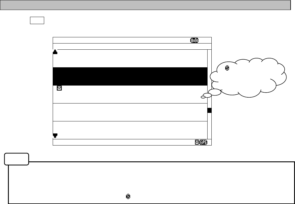
6-22
6.2.7.4 Save message list
Press the DISP key several times. The list of the messages that is currently saved appears.
Only the list of messages saved by “Message list 1” or “Message list 2” is displayed.
- Selecting of each message, scrolling, saving, and the printing method are carried out in the same
procedure as the message list 1.
Refer to the operation procedure of the message list 1 about operation.
- The save message list does not display “ ” mark which shows the saved message.
Fig.6-4 Save message list
SAVE MSG SORT:DATE
Ⅵ
ID FREQ LINES DATE TIME
IA01 4209.5 15 28/12/05 12:34
STATION : YOKOHAMA
MSG TYPE: NAVIGATIONAL WARNINGS
KA04 518 10 28/12/05 12:33
STATION : KUSHIRO
MSG TYPE: NAVIGATIONAL WARNINGS
IA07 490 20 28/12/05 12:32
STATION : YOKOHAMA
MSG TYPE: NAVIGATIONAL WARNINGS
KC10 490 12 27/12/05 18:30
STATION : KUSHIRO
MSG TYPE: ICE REPORTS
KH13 518 5 27/12/05 18:29
STATION : KUSHIRO
MSG TYPE: LORAN MESSAGE
DATA: 21/ 37
“ ” mark is not
displayed on this
screen.
Notes
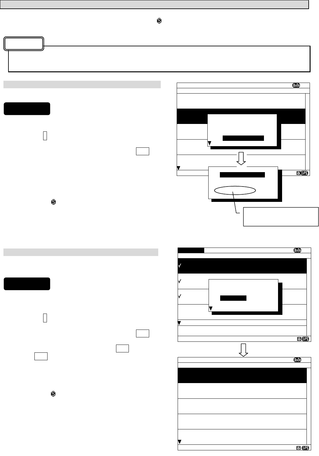
6-23
a. Delete the saved message
If the message is deleted from the save message list, “ ” mark displayed on the message list 1 will also be
deleted.
The message is deleted after stored for 70 hours, and the message is deleted from the message list 1
and 2.
Delete one message
The selected message can be deleted.
1) Move cursor onto the message to delete.
2) Press the * key. The sub screen appears.
3) Select the “DELETE MENU”, and press the ENT key.
4) Select the “[SELECT MSG]” in the sub screen of
“DELETE MANU”.
5) After message deleting has been completed, the
selected message is deleted from the save message
list and the “ “ mark is deleted from the message list
1.
In addition, the message is deleted after stored for 70
hours, and the message is deleted from the message
list 1 and 2.
Delete messages at the same time
The messages which put the check mark can be deleted at
the same time.
1) Put check marks in the same procedure as "c.Put a
check mark" of "6.2.6.2 Message list 1."
2) Press the * key. The sub screen appears.
3) Select the “DELETE MENU”, and press the ENT key.
5) Select the “[CHECK MSG]”, and the ENT key.
4) If the ENT key is pressed after selecting “[RESET
CHECK]”, all check marks are cleared.
5) After message deleting has been completed, the
selected message has deleted from the save message
list and the “ “ mark is deleted from the message list
1.
The message is deleted after stored for 70 hours, and
the message is deleted from the message list 1 and 2.
SAVE MSG SORT:DATE XI
ID FREQ LINES DATE TIME
IA01 4209.5 15 09/06/04 12:34
STATION : YOKOHAMA
MSG TYPE: NAVIGATIONAL WARNINGS
KA04 518 10 09/06/04 10:34
STATION : KUSIRO
MSG TYPE: NAVIGATIONAL WARNINGS
IA07 490 20 04/06/09 09:34
STATION : YOKOHAMA
MSG TYPE: NAVIGATIONAL WARNINGS
KC10 490 12 04/06/09 05:34
STATION : YOKOHAMA
MSG TYPE: ICE REPORTS
KH13 518 5 09/06/04 05:34
STATION : KUSIRO
MSG TYPE: LORAN MESSAGE
DATA: 21438
*SET UP*
LIST_
[REVERSE]
[CHECK]
DELETE MENU
PRINT MENU
*DELETE MENU*
[SELECT MSG]
[CHECK MSG]
[RESET CHECK]
[CANCEL]
To display to previous
screen, select “[CANCEL]”.
CHECK SORT:DATE XI
ID FREQ LINES DATE TIME
IA01 4209.5 15 09/06/04 12:34
STATION : YOKOHAMA
MSG TYPE: NAVIGATIONAL WARNINGS
KA04 518 10 09/06/04 10:34
STATION : KUSIRO
MSG TYPE: NAVIGATIONAL WARNINGS
IA07 490 20 04/06/09 09:34
STATION : YOKOHAMA
MSG TYPE: NAVIGATIONAL WARNINGS
KC10 490 12 04/06/09 05:34
STATION : YOKOHAMA
MSG TYPE: ICE REPORTS
KH13 518 5 09/06/04 05:34
CHECKING - PRESS [ENT] KEY
FINISHED - PRESS [*] KEY
DATA: 21/ 37
*SET UP*
LIST
[REVERSE]
[CHECK]
DELETE MENU
PRINT MENU
SAVE MSG SORT:DATE XI
ID FREQ LINES DATE TIME
KC10 490 12 09/06/05 05:34
STATION : YOKOHAMA
MSG TYPE: ICE REPORTS
KH13 518 5 09/06/05 05:34
STATION : KUSIRO
MSG TYPE: LORAN MESSAGE
IA11 518 10 08/06/05 22:20
STATION : YOKOHAMA
MSG TYPE: NAVIGATIONAL WARNINGS
IA13 518 14 08/06/05 18:20
STATION : YOKOHAMA
MSG TYPE: NAVIGATIONAL WARNINGS
IA42 518 28 07/06/05 22:21
STATION : YOKOHAMA
MSG TYPE: NAVIGATIONAL WARNINGS
DATA: 18/ 34
Caution
Procedures
Procedures
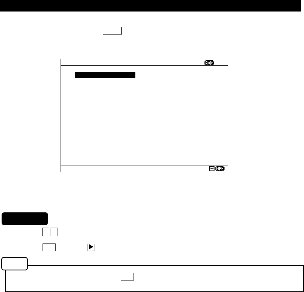
6-24
6.3 MAIN MEMU
Main menu displays menu items for setting, and maintenance, etc.
To display the Main menu, press the MENU key during operation.
1. Press the ▲ ▼ key to select the menu item.
2. When the ENT key or the key is pressed, the menu screen of selected item is displayed.
Previous screen is displayed when the CLR key is pressed. (Such as message text display or message
list 1, etc).
The outlines of menus are as follows;
1. RX STATION: Displays the menu for selecting receiving stations (See 6.3.1)
2. MESSAGE TYPE: Displays the menu for selecting message types (See 6.3.2)
3. DISPLAY: Displays the menu for setting the display unit. (See 6.3.3)
4. NAVTEX: Displays the menu for setting the NAVTEX receiver. (See 6.3.4)
5. MAINTENANCE: Displays the maintenance menu. (See 6.3.5)
6. LANGUAGE: Selects the menu display language. (See 6.3.6)
[EXIT]: Return to the previous screen (Such as message text display or message list 1,
etc.)
Fig.6-5 Main menu
MAIN MENU
ⅤⅢ
1.RX STATION_
2.MESSAGE TYPE
3.DISPLAY
4.NAVTEX
5.MAINTENANCE
6.LANGUAGE: ENGLISH
[EXIT]
Procedures
Notes
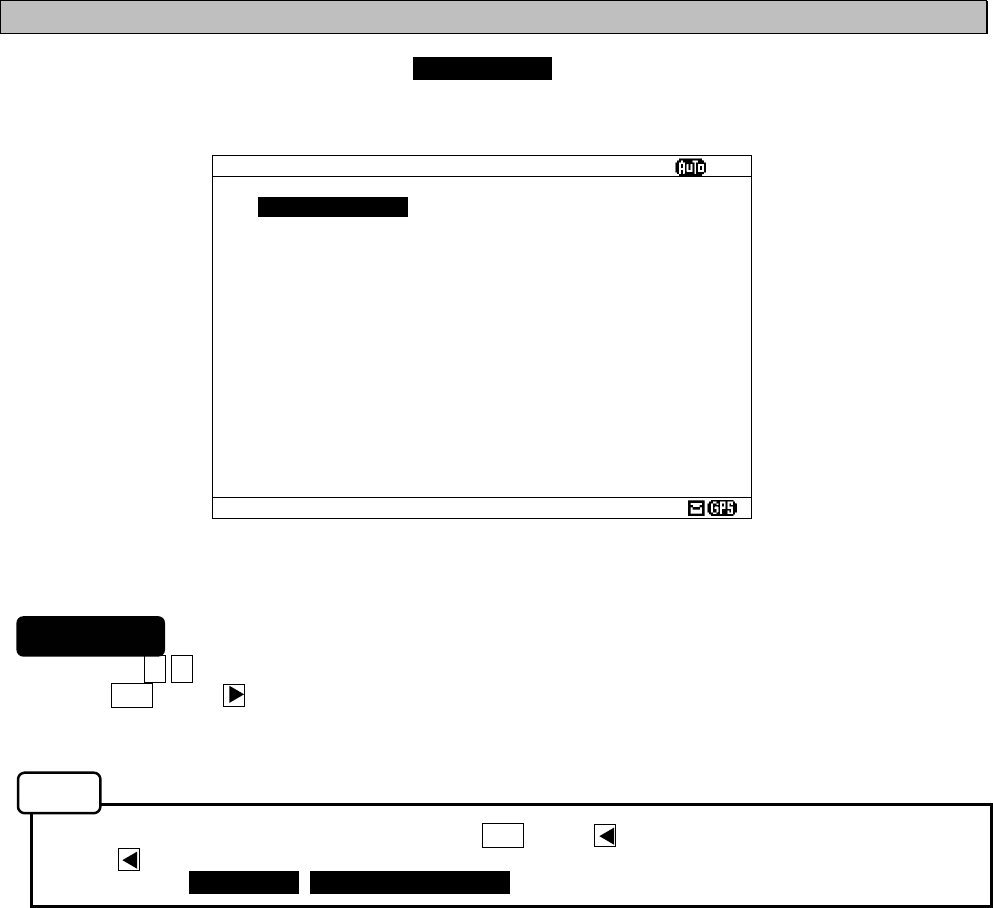
6-25
6.3.1 RX STATION screen
To display RX STATION menu screen, select 1. RX STATION.
1. Press the ▲ ▼ key to select the menu item.
2. When ENT key or key is pressed, the menu screen of selected item is displayed.
- When cursor is on the item 1 and 2, cursor moves to the right side of ":"
- When cursor is on the item 3 and 4, the menu screen of item 3 and 4 appears.
- To return to the MAIN MENU screen, press the CLR key or key.
- If the key is pressed when cursor is on the right side of ":" of item 1 and 2, cursor returns on the
item 1 and 2. (1.RX MODE, 2.OPERATING FREQ.)
The outlines of Menus are as follows;
1. RX MODE: Select “AUTO” or “MANUAL” as the receiving station selection mothod.
(See 6.3.1.1)
2. OPERATING FREQ.: Select receiving channels. (See 6.3.1.2)
3. AUTO MODE SETTING: Displays the menu screen by automatically selecting the receiving station
in each NAVAREA (Navigation area).
(See 6.3.1.3)
4. MANUAL MODE SETTING: Displays the menu screen for selecting the receiving station regardless of
NAVAREA. (See 6.3.1.4)
Fig.6-6 RX STATION menu screen
RX STATION
ⅤⅢ
1.RX MDOE: AUTO
2.OPERATING FREQ.:RX1/RX2/RX3
3.AUTO MODE SETTING
4.MANUAL MODE SETTING
Procedures
Notes
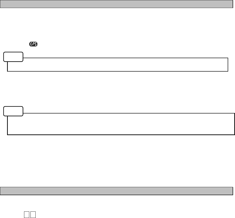
6-26
6.3.1.1 Receiving mode setting (RX MODE)
The automatic select mode and the manual select mode for RX station :
- AUTO: Automatic select mode
When normal GPS position data is inputted, the position and NAVAREA of a ship are automatically
specified, and the message of the receiving station in the NAVAREA is received.
(The “ “ mark is displayed on the status bar.)
“AUTO” can be selected only when the GPS data is inputted.
- MANUAL: Manual select mode
Regardless of the NAVAREA, messages are received according to the station selection settings of
each channel.
The information of code number “00” is always received, displayed and stored automatically
regardless of the setting.
(Refer to “6.2.7.1 Message text”.)
6.3.1.2 Receiving channel setting (OPERATING FREQ.)
A receiving channel selection
Press the ▲ ▼ key and select the following items;
- RX1 (518 kHz)/ RX2 (490 kHz)/ RX3 (4209.5 kHz)
- RX1 / RX2
- RX1 / RX3
RX1 (518kHz) is always selected.
Notes
Notes
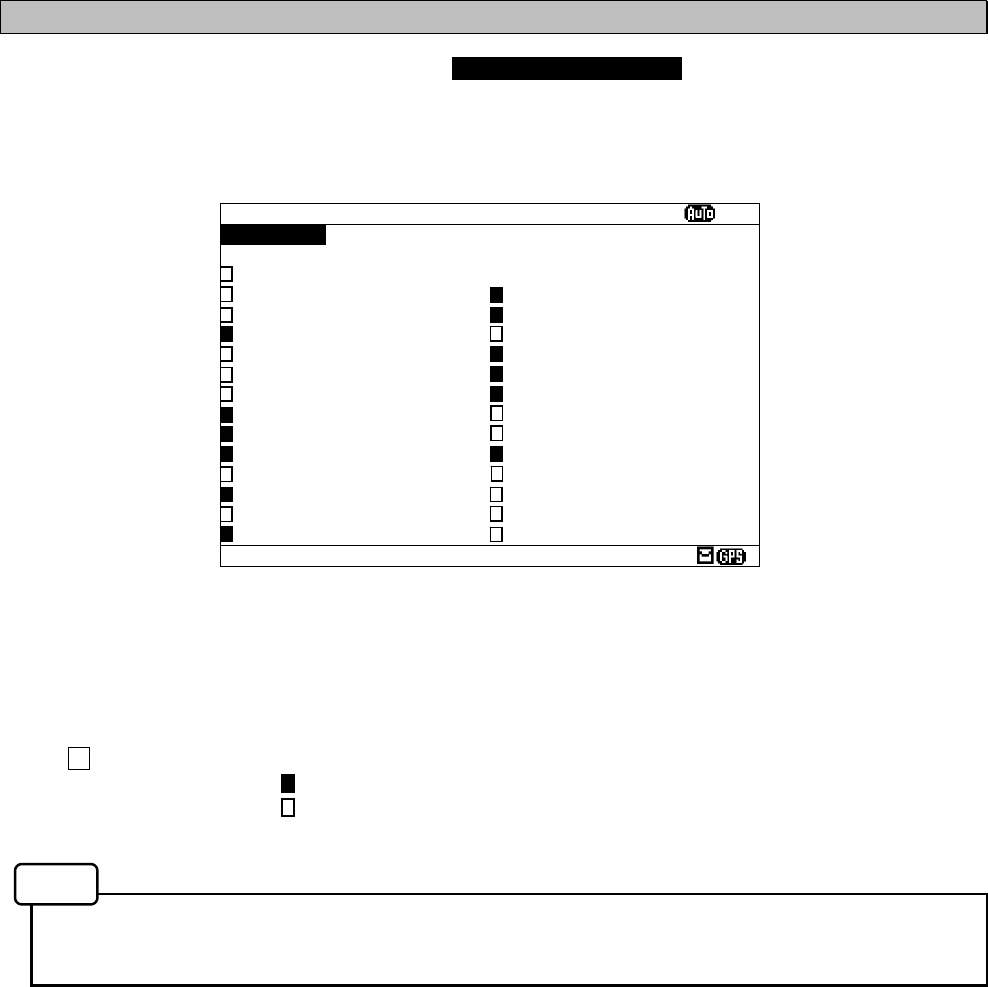
6-27
6.3.1.3 Automatic receiving station selection (AUTO MODE SETTING)
To display AUTO MODE SETTING screen, select 3.AUTO MODE SETTING from RX STATION menu (6.3.1).
Select the receiving station of each channel for every NAVAREA.
The items of the receiving station selection screen (auto mode) are as follows;
- NAVAREA: Select the NAVAREA (I - XVI).
- FREQUENCY: Select the channel (RX1 (518k), RX2 (490k), RX3 (4209.5k)).
- SELECT ALL: Select all the stations from A to Z.
: A message is received.
: A message is not received.
- Receiving station A – Z: Select receiving stations from A to Z
- When GPS data is inputted, the receiving station in your NAVAREA is automatically displayed in the
selection screen. Otherwise, the stations in NAVAREA1 are displayed first.
Fig.6-7 The receiving station selection screen (Auto mode setting)
STATION(AUTO)
ⅩⅠ
NAVAREA :
ⅩⅠ
FREQUENCY:RX1(518K)
SELECT ALL
A:JAYAPURA N:GUANGZHOU
B:AMBON O:FUZHOU
C:SINGAPORE P:MEILUNG
D:MAKASSAR Q:SHANGHAI
E:JAKARTA R:DALIAN
F:BANGKOK RADIO S:SANDAKAN
G:NAHA T:MIRI
H:MOJI U:PENANG
I:YOKOHAMA V:CHUKPYON/GUAM
J:OTARU W:PYONSAN
K:KUSHIRO/DANANG X:HO CHI MINH
L:HONG KONG Y:
M:SANYA Z:
Notes
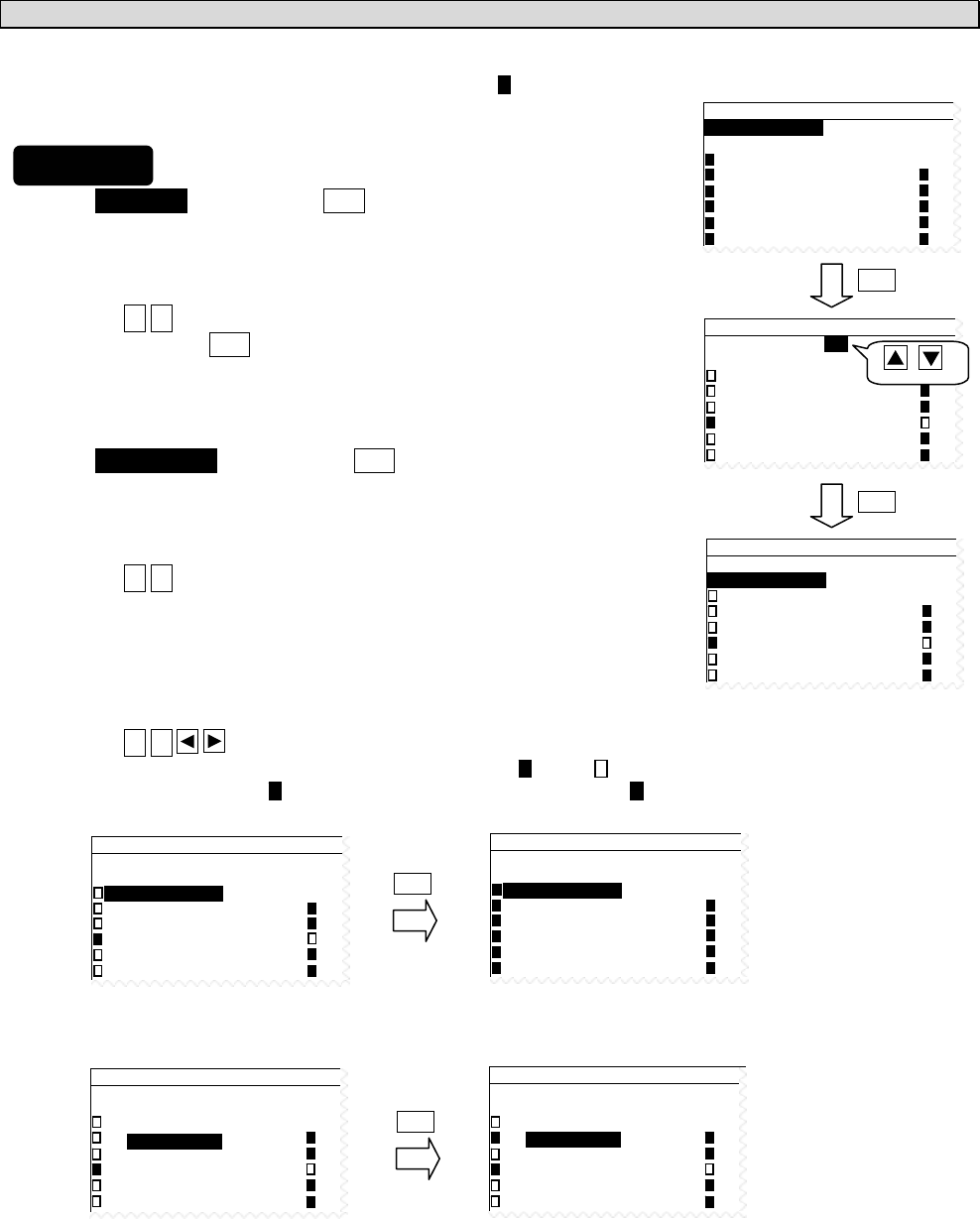
6-28
a. Select receiving stations
Select the receiving station of each channel for every NAVAREA.
All stations of initial setting are “A message is received: ”
1) Select NAVAREA, and press the ENT key.
Cursor moves to the right side of ":" (on a number).
2) Press the ▲ ▼ key and select the number of NAVAREA.
And then, press the ENT key.
The cursor moves to the lower line (on the “FREQUENCY”).
3) Select FREQUENCY, and press the ENT key.
Cursor moves to the right side of ":" (on the “RX1”).
4) Press the ▲ ▼ key and select a channel.
RX1 (518K): 518 kHz
RX2 (490K): 490 kHz
RX3 (4209.5K): 4209.5 kHz
5) Press the ▲ ▼ key to select a receiving station for setting.
- Pressing the ENT key switches alternately between “ “ and “ “.
- If the “SELSCT ALL” is “ ”, all station (A-Z) settings changes to “ ”.
STATION(AUTO)
NAVAREA :
ⅩⅠ
FREQUENCY:RX1(518K)
SELECT ALL
A:JAYAPURA N
B:AMBON O
C:SINGAPORE P
D:MAKASSAR Q
E:JAKARTA R
STATION(AUTO)
NAVAREA :
ⅩⅠ
FREQUENCY:RX1(518K)
SELECT ALL
A:JAYAPURA N
B:AMBON O
C:SINGAPORE P
D:MAKASSAR Q
E:JAKARTA R
ENT
STATION(AUTO)
NAVAREA :
ⅩⅠ
FREQUENCY:RX1(518K)
SELECT ALL
A:JAYAPURA N
B:AMBON O
C:SINGAPORE P
D:MAKASSAR Q
E:JAKARTA R
STATION(AUTO)
NAVAREA :
ⅩⅠ
FREQUENCY:RX1(518K)
SELECT ALL
A:JAYAPURA N
B:AMBON O
C:SINGAPORE P
D:MAKASSAR Q
E:JAKARTA R
ENT
STATION(AUTO)
NAVAREA__:
ⅠⅩ
FREQUENCY:RX1(518K)
SELECT ALL
A:BUSHEHR N
B:HAMALA O
C: P
D: Q
E: R
ENT
STATION(AUTO)
NAVAREA :
ⅩⅠ
FREQUENCY:RX1(518K)
SELECT ALL
A:JAYAPURA N
B:AMBON O
C:SINGAPORE P
D:MAKASSAR Q
E:JAKARTA R
aa, aa
STATION(AUTO)
NAVAREA :
ⅩⅠ
FREQUENCY:RX1(518K)
SELECT ALL
A:JAYAPURA N
B:AMBON O
C:SINGAPORE P
D:MAKASSAR Q
E:JAKARTA R
ENT
Selection of NAVAREA
(a) Selection of all stations
(b) Selection of each station
Procudure
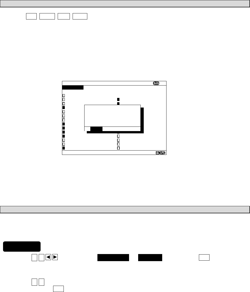
6-29
b. Cancel settings
When the CLR/ MENU/ DISP/ USER key is pressed while setting up “a. Select receiving stations”, the
information screen (the sub screen) as shown in the following figure is displayed.
Select “OK” or “CANCEL”.
OK: Canceling the receiving station settings, the screen changes according to the pressed
key.
CANCEL: The information screen is closed. Continu the receiving station settings.
c. Set up the next channel (or NAVAREA)
After a setup of a channel (or NAVAREA) finishes, the next channel (or NAVAREA) can be set up
continuously.
1) Press the ▲ ▼ key for selecting FREQUENCY (or NAVAREA), and press the ENT key.
Cursor moves to the right side of ":"
2) Press the ▲ ▼ key and select the number of NAVAREA.
And then, press the ENT key.
3) Select a receiving station in the same procedures as “a. Select receiving stations”.
STATION(AUTO)
ⅩⅠ
NAVAREA :
ⅩⅠ
FREQUENCY:RX1(518K)
SELECT ALL
A:JAYAPURA N:GUANGZHOU
B:AMBON O:FUZHOU
C:SINGAPORE P:MEILUNG
D:MAKASSAR Q:SHANGHAI
E:JAKARTA R:DALIAN
F:BANGKOK RADIO S:SANDAKAN
G:NAHA T:MIRI
H:MOJI U:PENANG
I:YOKOHAMA V:CHUKPYON/GUAM
J:OTARU W:PYONSAN
K:KUSHIRO/DANANG X:HO CHI MINH
L:HONG KONG Y:
M:SANYA Z:
*STNS(AUTO) SET*
EXIT WITHOUT
SAVING.
ARE YOU SURE?
(SAVE:PRESS
’’
*
’’
KEY)
[OK] [CANCEL]
Procedures
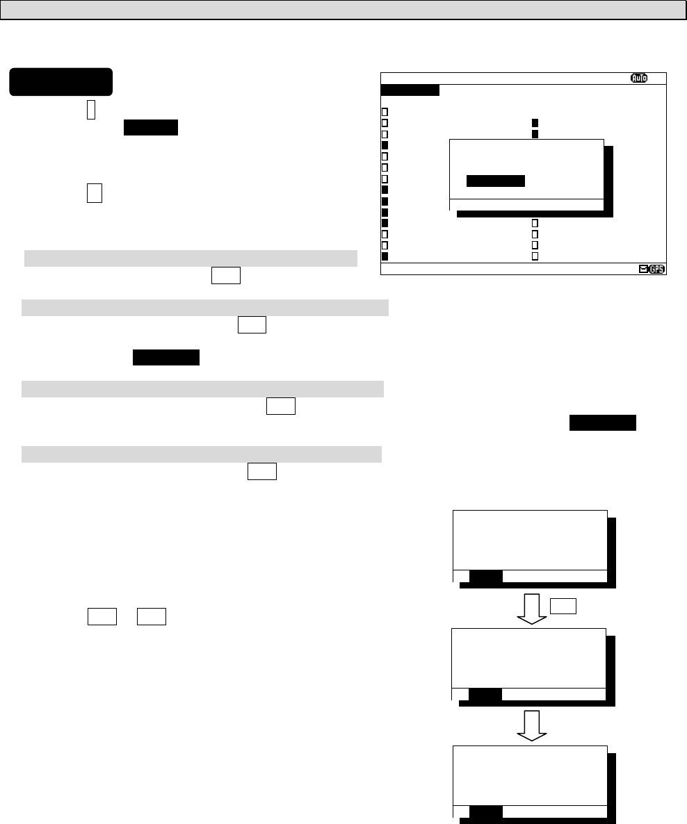
6-30
d. Save (or Clear) settings
Save (or clear) the settings on the sub screen after setting up.
1) Press the * key. The sub screen appears.
Cursor is on the [CLEAR].
2) Press the ▼ key and select the following items.
3) Save settings
Select the [OK], and press the ENT key.
Clear only settings of the screen that is currently open
Select the [CLEAR], and press the ENT key.
The receiving station settings of the screen that is currently open are restored to its former state, and the
cursor returns to NAVAREA.
Clear all settings
Select the [ALL CLEAR], and press the ENT key.
All the receiving station settings are restored to its former state, and the cursor returns to NAVAREA.
Continue setting up
Select the [CANCEL], and press the ENT key.
This sub screen is closed.
4) To start save precess, select [OK].
Then, “SAVE OK” is displayed on the sub screen.
Press the ENT or CLR key.
RX STATION menu screen appears.
STATION(AUTO)
ⅩⅠ
NAVAREA :
ⅩⅠ
FREQUENCY:RX1(518K)
SELECT ALL
A:JAYAPURA N:GUANGZHOU
B:AMBON O:FUZHOU
C:SINGAPORE P:MEILUNG
D:MAKASSAR Q:SHANGHAI
E:JAKARTA R:DALIAN
F:BANGKOK RADIO S:SANDAKAN
G:NAHA T:MIRI
H:MOJI U:PENANG
I:YOKOHAMA V:CHUKPYON/GUAM
J:OTARU W:PYONSAN
K:KUSHIRO/DANANG X:HO CHI MINH
L:HONG KONG Y:
M:SANYA Z:
*STNS(AUTO) SET*
SAVE CHANGES TO
THIS SETTING?
[CLEAR]
[ALL CLEAR]
[OK] [CANCEL]
*STNS(AUTO) SET*
NOW SAVING...
[OK] [CANCEL]
*STNS(AUTO) SET*
SAVE OK
[OK] [CANCEL]
*STNS(AUTO) SET*
SAVE CHANGES TO
THIS SETTING?
[CLEAR]
[ALL CLEAR]
[OK] [CANCEL]
ENT
Saving is completed
Procedures
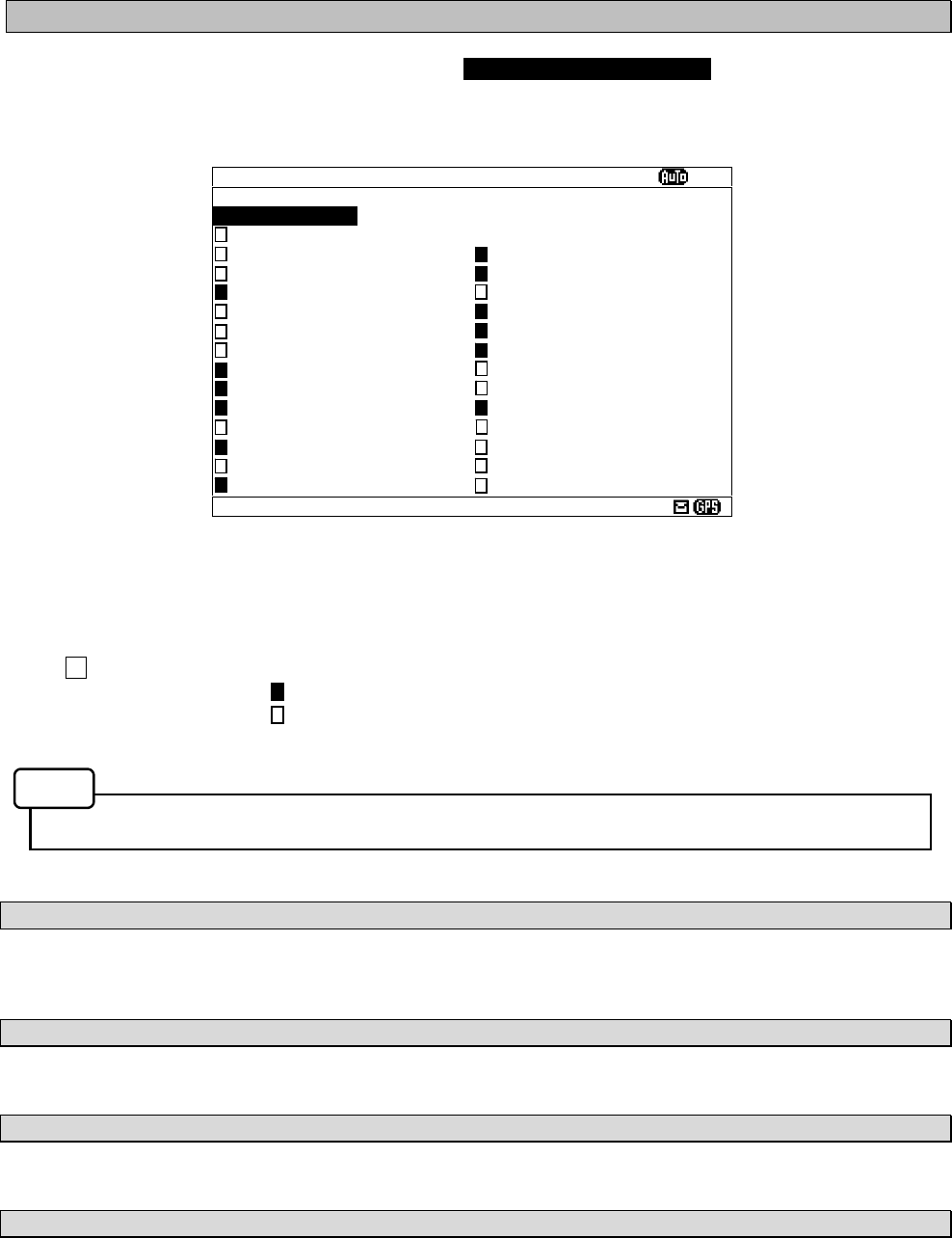
6-31
6.3.1.4 Manual receiving station selection (MANUAL MODE SETTING)
To display MANUAL MODE SETTING screen, select 4.MANUAL MODE SETTING from RX STATION menu
(6.3.5).
Select the receiving station of each channel. There is no setup of NAVAREA.
The items of the receiving station selection screen (manual mode) are as follows;
- FREQUENCY: Select the channel (RX1 (518k), RX2 (490k), RX3 (4209.5k)).
- SELECT ALL: Select all the stations from A to Z.
: A message is received.
: A message is not received.
- Receiving station A – Z: Select receiving stations from A to Z
When this screen is displayed, the receiving station of RX1 is displayed first.
a. Select receiving stations
Start with selection of "FREQUENCY".
Carry out the procedure from section 3) to 5) of p.6-28 “a. Select receiving stations”
b. Cancel settings
Carry out “b. Cancel settings” of p.6-29.
c. Set up the next channel (or NAVAREA)
Carry out the procedure from section 1) to 3) of p.6-29 “c. Set up the next channel (or NAVAREA)”.
d. Save (or Clear) settings
Carry out the procedure from section 1) to 4) of p.6-30 “d. Save (or Clear) settings”.
Fig.6-8 The receiving station selection screen (Manual mode setting)
STATION(MANUAL)
ⅩⅠ
FREQUENCY:RX1(518K)
SELECT ALL
A: N:
B: O:
C: P:
D: Q:
E: R:
F: S:
G: T:
H: U:
I: V:
J: W:
K: X:
L: Y:
M: Z:
Notes
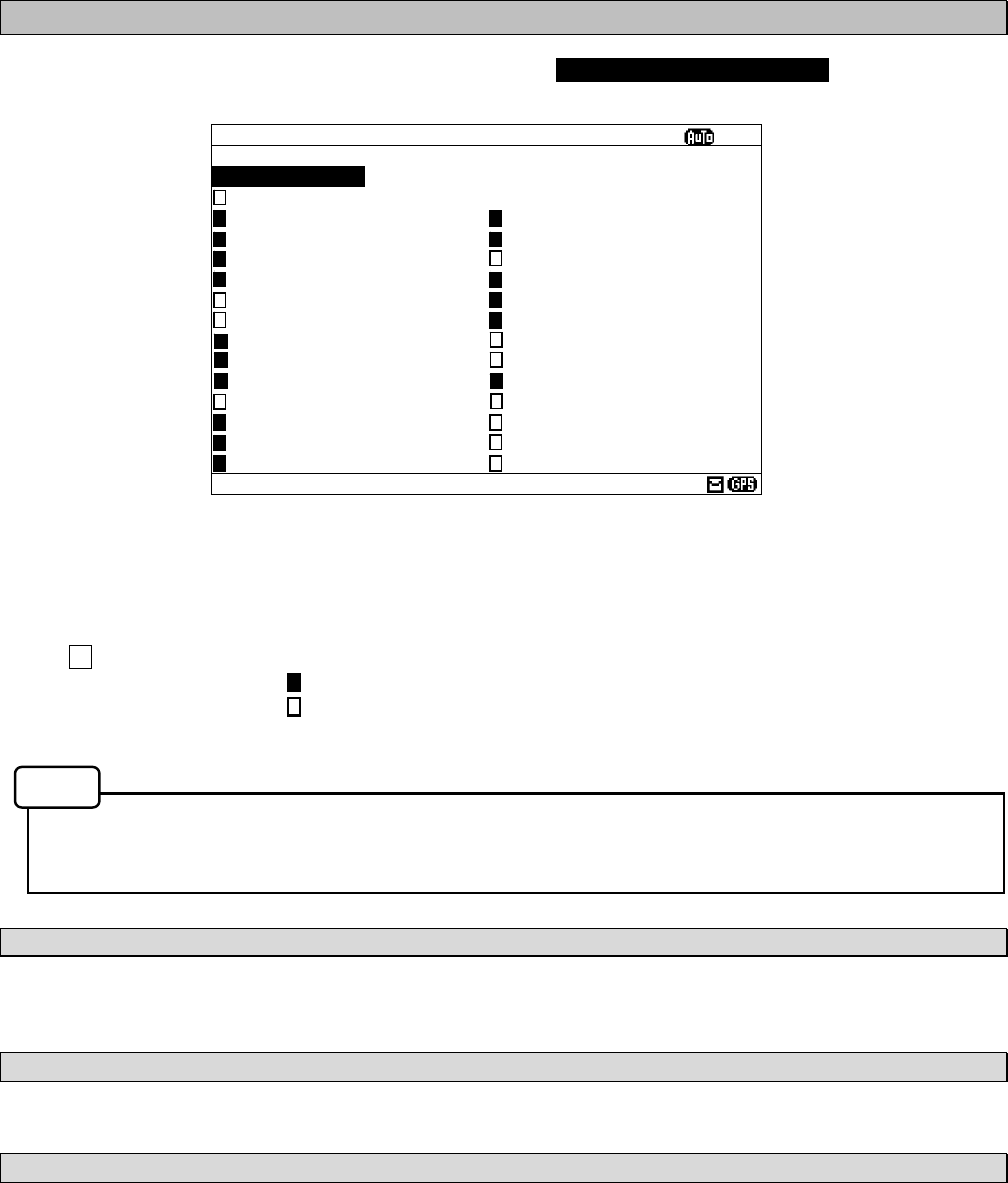
6-32
6.3.2 Receiving message type settings (MESSAGE TYPE SETTING)
To display MESSAGE TYPE SETTING menu screen, select 2. MESSAGE TYPE SETTING.
The items of the receiving message type selection screen are as follows;
- FREQUENCY: Select the channel (RX1 (518k), RX2 (490k), RX3 (4209.5k)).
- SELECT ALL: Select all the messages from A to Z.
: A message is received.
: A message is not received.
- Receiving message A – Z : Select receiving message from A to Z
Navigational warning [A], Meteorological warning [B], Search and rescue information/piracy and armed
robbery [D], Navigational warning (additional) [L] are obliged to receive a message. These message
types setting cannot be changed.
a. Select receiving message types
Start with selection of "FREQUENCY".
Carry out the procedure from section 3) to 5) of p.6-28 “a. Select receiving stations”.
b. Cancel settings
Carry out “b. Cancel settings” of p.6-29.
c. Save (ro Clear) settings
Carry out the procedure from section 1) to 4) of p.6-30 “d. Save (or Clear) settings”.
Fig.6-9 MESSAGE TYPE menu screen
MSG TYPE
ⅩⅠ
FREQUENCY:RX1(518K)
SELECT ALL
A:NAV WARNINGS N:[SPARE]
B:MET WARNINGS O:[SPARE]
C:ICE REPORT P:[SPARE]
D:SERCH & RESCUE Q:[SPARE]
E:MET FORECAST R:[SPARE]
F:PILOT SERVICE S:[SPARE]
G:DECCA T:[SPARE]
H:LORAN U:[SPARE]
I:[SPARE] V:SPECIAL
J:SATNAV W:SPECIAL
K:OTHER NAVAID X:SPECIAL
L:NAV WARNINGS Y:SPECIAL
M:[SPARE] Z:NO MESSAGES
Notes
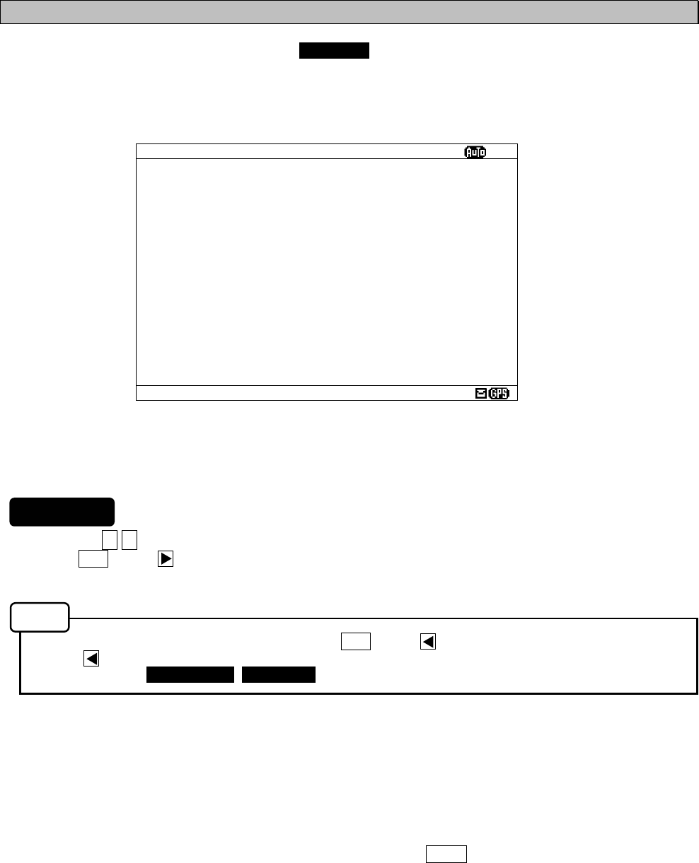
6-33
6.3.3 DISPLAY setting menu (DISPLAY SET)
To display DISPLAY SET menu screen, select 3.DISPLAY from MAIN MENU (6.3).
Display form, a buzzer, etc. can be set up on this screen.
1. Press the ▲ ▼ key to select the menu item.
2. When ENT key or key is pressed, the menu screen of selected item is displayed.
- When cursor is on the item 1-4 and 6, cursor moves to the right side of ":"
- When cursor is on the item 5, the menu screen of item 5 appears.
- To return to the MAIN MENU screen, press the CLR key or key.
- If the key is pressed when cursor is on the right side of ":" of item 1-4 and 6, cursor returns on the
item 1-4 and 6. (1.CONTRAST, 2. DIMMER, ....)
The outlines of menus are as follows;
1. CONTRAST: Adjust the contrast of this display. (See 6.3.3.1)
2. DIMMER: Set up the brightness level of this display. (See 6.3.3.2)
3. BUZZER: Select buzzer ON/OFF. (See 6.3.3.3)
4. LOCAL TIME: Input local time. (See 6.3.3.4)
5. USER KEY SETTING: Assign the often used function for the USER key (See 6.3.3.5)
6. POS/TIME DISP.SET: Set up the display of the POSITION/TIME screen. (See 6.3.3.6)
Fig.6-10 DISPLAY SET menu screen
DISPLAY SET
ⅩⅠ
1.CONTRAST : 10
2.DIMMER
- MAXIMUM : 10
- TYPICAL : 6
- MINIMUM : 2
3.BUZZER : ON
- ALARM MSG : ON
(FOR MESSAGE TYPE:A,B,L)
- RECEIVED MSG : ON
- NAVTEX ALARM : ON
- CLICK : ON
4.LOCAL TIME : ON
(TIME DIFFERENCE): -11:59
5.USER KEY SETTING
6.POS/TIME DISP.SET(1):POS
(2):TIME/NAV
Procedures
Notes
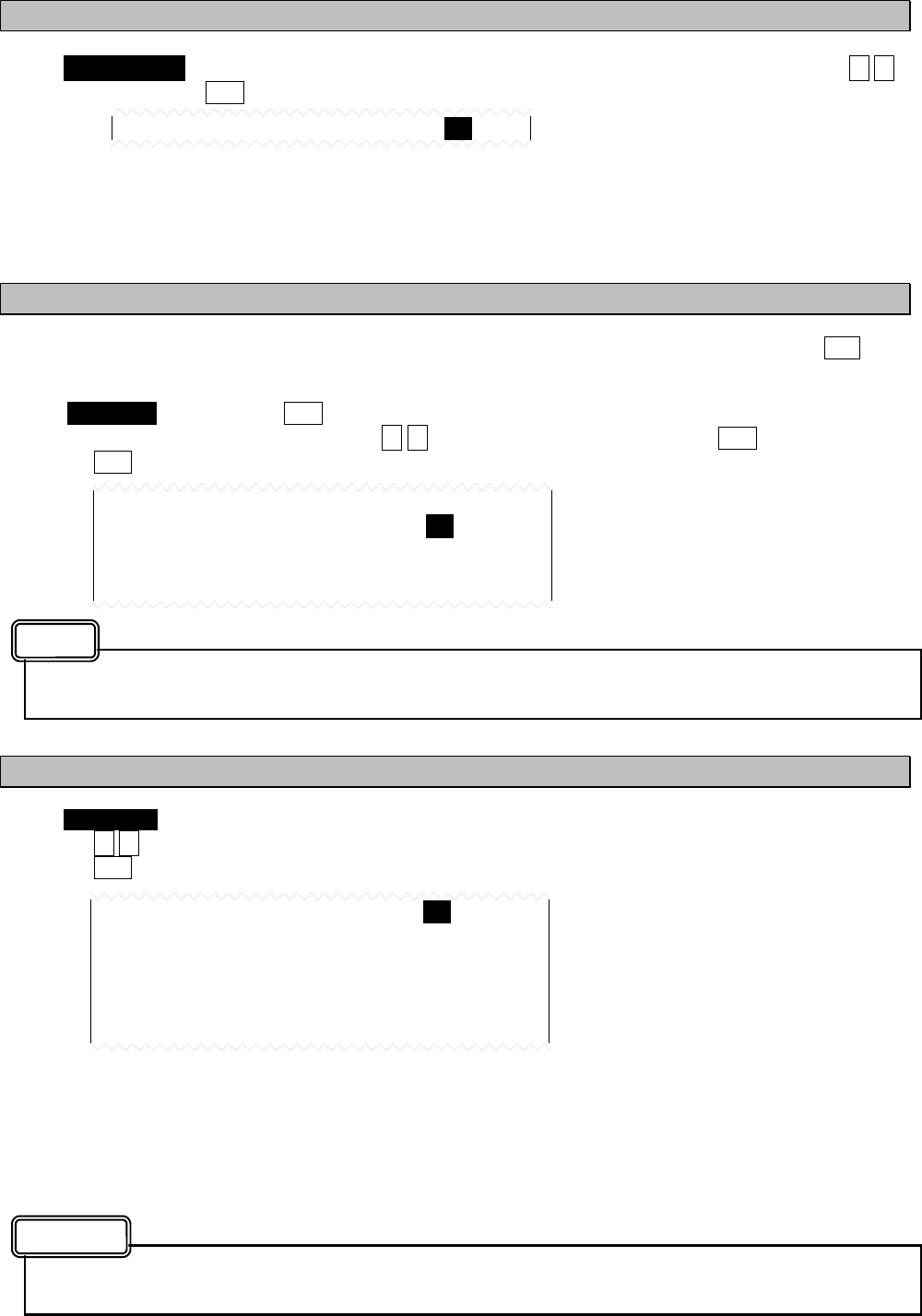
6-34
6.3.3.1 Contrast adjustment (CONTRAST)
When 1. CONTRAST is selected, CONTRAST is ready to be entered. To adjust the contrast, press the ▲ ▼
key, and then press the ENT key.
The adjustment of the contrast
- “1” is the darkest.
- “13” is the lightest.
The initial setting is “7”.
6.3.3.2 Brightness settings (DIMMER)
Brightness can be changed into four levels (Maximum, Typical, Minimum and off) by pressing the DIM key.
These brightness levels are set up in this item.
Select 2.DIMMER, and press the ENT key. Cursor moves to the right side of ":".
Number and brightness is changed when the ▲ ▼ key is pressed, and then press the ENT key.
Press the ENT key after setting up to "MINIMUM". All setting values are saved.
“MAXIMUM” should enter the largest numerical value and “MINIMUM” should enter the smallest
numerical value.
6.3.3.3 Buzzer settings (BUZZER)
When 3. BUZZER is selected, each buzzer functions can be set enable (ON) or disable (OFF) as followings.
Press the ▲ ▼ key and select the “ON” or “OFF”.
Press the ENT key after setting up to "CLICK". All buzzer settings are saved.
BUZZER: OFF: All buzzer functions are disabled.
ON: Each buzzer function as shown below can be enabled.
- ALARM MSG: When a message (A, B and L) is received.
- RECEIVED MSG: When a message (other than A, B and L) is received.
- NAVTEX ALARM: When a failure alarm occurs.
- CLICK: When a key is pressed.
When search and rescue message (D) is received, buzzer sounds. The SAR buzzer sound can not be
set to “OFF (disable)”.
1.CONTRAST : 10
3.BUZZER : ON
- ALARM MSG : ON
(FOR MESSAGE TYPE:A,B,L)
- RECEIVED MSG : ON
- NAVTEX ALARM : ON
- CLICK : ON
ON: A buzzer is sounded.
OFF: A buzzer is not sounded.
2.DIMMER
- MAXIMUM : 10
- TYPICAL : 8
- MINIMUM : 4
Caution
Notes
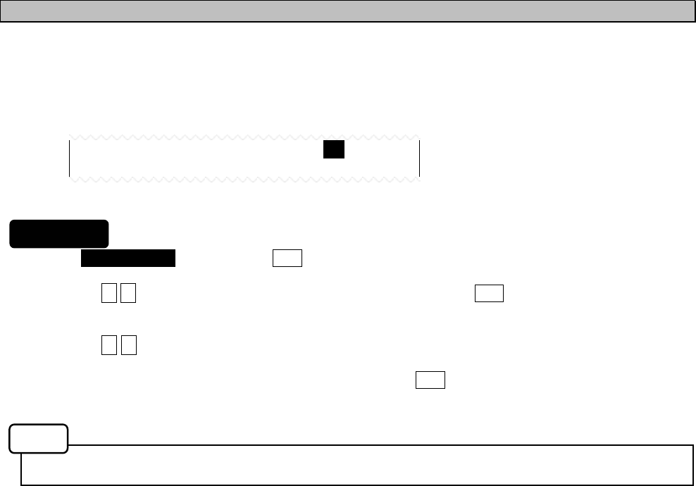
6-35
6.3.3.4 Time Difference setting (LOCAL TIME)
"LOCAL TIME" can set up time difference to UTC.
When “ON” is selected, “(LOCAL)” is displayed in the POSITION/TIME screen. The time of the
POSITION/TIME screen displays the numerical value which added time difference to UTC.
When “OFF” is selected, “(UTC)” is displayed.
1. Select 4.LOCAL TIME, and press the ENT key. Cursor moves to the right side of ":".
2. Press the ▲ ▼ key and select the “ON” or “OFF”, and then press the ENT key.
The cursor moves to the lower line.
3. Press the ▲ ▼ key and select “+ (add) “ or “- (sub)”. Next, input the numerical value within the range of
00:00 to 12:00. ( -12:00 to +12:00)
To save the "LOCAL TIME" settings, cursor should press the ENT key on the rightmost position
(minute).
The setup time difference is displayed on the POSITION/TIME screen.
4.LOCAL TIME : ON
(TIME DIFFERENCE): +09:00
Procudure
Notes
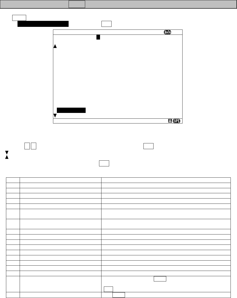
6-36
6.3.3.5 Assigning to the USER key (USER KEY SETTING)
The USER key can be assigned to the often used function (screen).
Select 5. USER KEY SETTING, and press the ENT key. USER KEY SETTING screen appears.
Press the ▲ ▼ key and select from “A” to “Z”, and then press the ENT key. “USER KEY” setting is saved.
“ “ mark is displayed on the bottom line when the USER KEY SETTING screen is able to scroll downward.
“ “ mark is displayed on the top line when the USER KEY SETTING screen is able to scroll upward.
To display DISPLAY menu screen, press the CLR.
Refer to the following table about selectable items;
Title Explanation
A MESSAGE LIST1 MESSAGE LIST 1 screen is displayed.
B MESSAGE LIST2 MESSAGE LIST 2 screen is displayed.
C SAVE MESSAGE LIST SAVE MESSAGE LIST screen is displayed.
D POSITION/ITME POSITION/TIME screen is displayed.
E RX STATION SETTING MENU RX STATION menu screen is displayed.
F AUTO MODE SETTING
AUTO MODE SETTING screen (RX STATION menu) is
displayed.
G MANUAL MODE SETTING MAMUAL MODE SETTING screen (RX STATION menu) is
displayed.
H MESSAGE TYPE SETTING MENU MESSAGE TYPE SETTING screen is displayed.
I DISPLAY SETTING MENU DISPLAY menu screen is displayed.
J USER KEY SETTING This screen (SER KEY SETTING) is displayed.
K NAVTEX SETTING MENU NAVTEX menu screen is displayed.
L MAINTENANCE MENU MAINTENANCE menu screen is displayed.
M SELF DIAGNOSIS SELF DIAGNOSIS screen (MAINTENANCE menu) is displayed.
N NAVTEX ALARM NAVTEX ALARM screen (MAINTENANCE menu) is displayed.
O STATUS STATUS screen (MAINTENANCE menu) is displayed.
P PORT MONITOR PORT MONITOR screen (MAINTENANCE menu) is displayed.
Y PRINT
Printing is started if the USER key is pressed on the screen
which can print the external printer. Printing is stopped if the
CLR key is pressed during printing.
Z NON USE
The USER key cannot be used.
Fig.6-11 USER KEY SETTING screen
USER KEY SETTING
ⅩⅠ
1.USER KEY: P
-----------------------------------
D:POSITION/TIME
E:RX STATION SETTING MENU
F:AUTO MODE SETTING
G:MANUAL MODE SETTING
H:MESSAGE TYPE SETTING MENU
I:DISPLAY SETTING MENU
J:USER KEY SETTING
K:NAVTEX SETTING MENU
L:MAINTENANCE MENU
M:SELF DIAGNOSIS
N:NAVTEX ALARM
O:STATUS
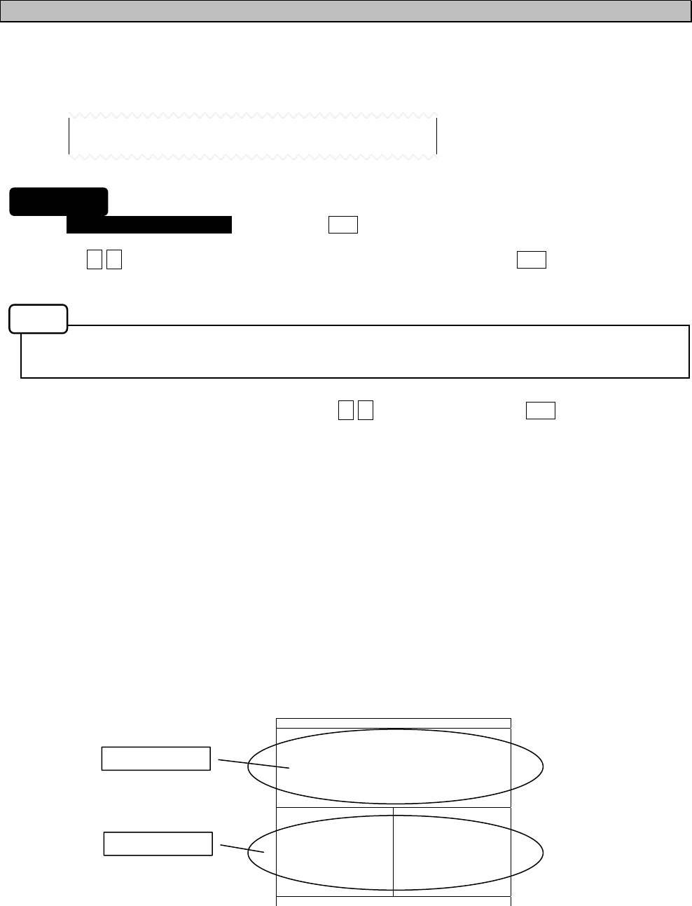
6-37
6.3.3.6 POSITION/TIME screen settings (POS/TIME DISP.SET)
"POS/TIME DISP.SET" can set up the item displayed on the POSITION/TIME screen.
POSITION/TIME screen can be displayed selecting items of “position (POS)”, “time (TIME)”, and
“navigational information (NAV)”.
1. Select 6.POS/TIME DISP. SET(1), and press the ENT key. Cursor moves to the right side of ":".
2. Press the ▲ ▼ key and select the “POS”, “TIME” or “OFF”, and then press the ENT key.
This item is displayed on the upside of the POSITION/TIME screen.
The setup time difference is displayed on the POSITION/TIME screen.
When you have selected "OFF", cursor ends the setup of this item, without moving to the lower line “(2)”.
3. The cursor moves to the lower line “(2)”. Press the ▲ ▼ key, and then press the ENT key.
This item is displayed on the downside of the POSITION/TIME screen.
(1): POS, The selectable items of “(2)” are as follows.
OFF, TIME, TIME/NAV
(1): TIME, The selectable items of “(2)” are as follows.
OFF, POS, POS/TIME
- When “OFF” is selected, only the item of (1) is displayed on POSITION/TIME screen.
- When “TIME” (or “POS”) is selected, this item is displayed on the downside of the POSITION/TIME
screen.
- When “TIME/NAV” (or “POS/NAV”) is selected, time is displayed on the left side, and navigational
information is displayed on the right side of the POSITION/TIME screen.
Ex) The following figure is an example when selecting “POS” and “TIME/NAV”.
(1): POS
(2): TIME/NAV
6.POS/TIME DISP.SET(1):POS
(2):TIME/NAV
POS/TIME XI
89
°
59.999
’
N
139
°
59.999
’
E
TIME 23:59(UTC)
DATA 31/12/05
(DD/MM/YY)
SOG: 102.2KT
COG: 359.9
°
HDT: 359.9
°
ROT:+127.1
°
/MIN
The item of (1)
The item of (2)
Procudure
Notes
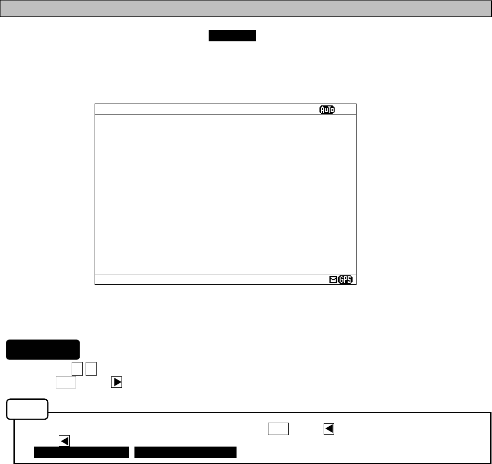
6-38
6.3.4 NAVTEXsetting menu (NAVTEX)
To display NAVTEX SET menu screen, select 4.NAVTEX from MAIN MENU (6.3).
Character size, printer setting, etc. can be set up on this screen.
1. Press the ▲ ▼ key to select the menu item.
2. When ENT key or key is pressed, the menu screen of selected item is displayed.
- To return to the MAIN MENU menu screen, press the CLR key or key.
- If the key is pressed when cursor is on the right side of ":", cursor returns on the item.
(1.CHARACTER SIZE, 2. CER DISP.SETTING, ....)
The outlines of menus are as follows;
1. CHARACTER SIZE: Select the character size (See 6.3.4.1)
2. CER DISP.SETTING: Add “CER” to the end of message (See 6.3.4.2)
3. MESSAGE SCROLL: Set up the message scroll function (See 6.3.4.3)
4. MESSAGE SPEED: Select the scrolling speed (See 6.3.4.4)
5. PRINTER PROPERTY: Set up the external printer connection (See 6.3.4.5)
Fig.6-12 NAVTEX SET menu screen
NAVTEX SET
ⅩⅠ
1.CHARACTER SIZE : NORMAL
2.CER DISP.SETTING : OFF
(CER:CHARACTER ERROR RATE)
3.MESSAGE SCROLL : ON
4.MESSAGE SPEED : FAST
5.PRINTER PROPERTY
- DATA OUT : MANUAL
- DATA FORMAT : ON
- BAUDRATE : 38.4KBPS
- FLOW CONTROL : NONE
- PRINT DIRECTION : UPRIGHT
Procedures
Notes
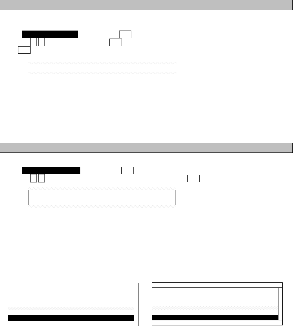
6-39
6.3.4.1 Character size setting (CHARACTER SIZE)
Displayed character can be changed into three sizes.
Select 1.CHARACTER SIZE, and press the ENT key. Cursor moves to the right side of ":".
Press the ▲ ▼ key, and then press the ENT key.
If the ENT key is pressed, the selected character size is saved, and the displayed character is changed.
The initial setting is “NORMAL”.
NORMAL: The normal character size: 13x9 dots
MEDIUM: The medium character size: 16x9 dots
LARGE: The large character size: 20x16 dots
6.3.4.2 CER setting (CER DISP.SETTING)
A message text can add “CER(*1)“ to the end of message.
Select 2.CER DISP.SETTING, and press the ENT key. Cursor moves to the right side of ":".
Press the ▲ ▼ key and select the “ON” or “OFF”, and then press the ENT key. This setting is saved
The initial setting is “OFF”.
ON: “CER” is displayed on the end of message.
OFF: “CER” is not displayed.
(*1): Character Error Rate
(When CER DISP.SETTING is set “ON”) (When CER DISP.SETTING is set “OFF”)
1.CHARACTER SIZE : NORMAL
2.CER DISP.SETTING : ON
(CER:CHARACTER ERROR RATE)
IA01 4209.5 15 04/06/09 12:34
123400 UTC JUNE 04
JAPAN NAVTEX N.W. NR 1260/2004
KEIHIN KO, TOKYO WEST PASSAGE.
DAYTIME DAILY UNTIL 28 JUNE 2004
35-35-02.0N 139-47-55.3E,WGS-84
(END OF MESSAGE CER : 3.5%)
LINE: 18/ 18
IA01 4209.5 15 04/06/09 12:34
123400 UTC JUNE 04
JAPAN NAVTEX N.W. NR 1260/2004
KEIHIN KO, TOKYO WEST PASSAGE.
DAYTIME DAILY UNTIL 28 JUNE 2004
35-35-02.0N 139-47-55.3E,WGS-84
(END OF MESSAGE)
LINE: 18/ 18
6-40
6.3.4.3 Automatic scrolling setting (MESSAGE SCROLL)
When character size has selected “LARGE”, a message text can be automatically scrolled on a screen.
Select 3.MESSAGE SCROLL, and press the ENT key. Cursor moves to the right side of ":".
Press the ▲ ▼ key and select the “ON” or “OFF”, and then press the ENT key. This setting is saved
The initial setting is “ON”
ON: A message text scroll.
OFF: A message text does not scroll.
6.3.4.4 Scrolling speed adjustment (MESSAGE SPEED)
The speed of automatic scrolling can be changed into three levels.
Select 4.MESSAGE SPEED, and press the ENT key. Cursor moves to the right side of ":".
Press the ▲ ▼ key and select the “ON” or “OFF”, and then press the ENT key. This setting is saved
The initial setting is “NORMAL”.
SLOW: A character scrolls at the slowest speed.
NORMAL: A character scrolls at the normal speed.
FAST: A character scrolls at the fastest speed.
3.MESSAGE SCROLL : ON
4.MESSAGE SPEED : NORMAL
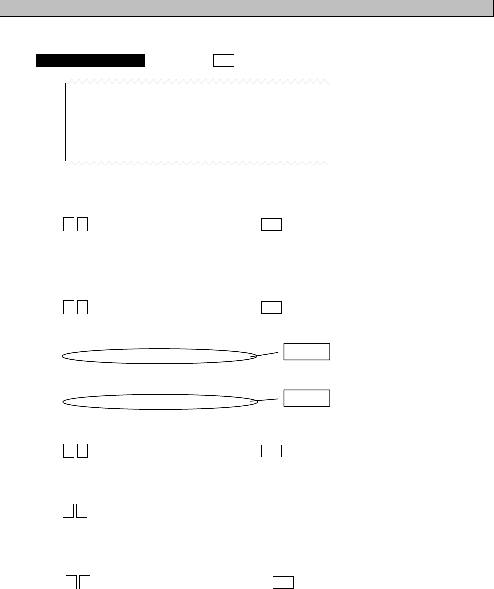
6-41
6.3.4.5 External printer settings (PRINTER PROPERTY)
Serial port (RS-232C: MAINTENANCE/PRINTER) conditions can be set up when connecting external printer.
Select 5.PRINTER PROPERTY, and press the ENT key. Cursor moves to the right side of ":".
After setting up to "FLOW CONTROL", press the ENT key. All settings are saved.
The explanations of each item are as follows;
(1) DATA OUT
The data output method for printer is set up.
Press the ▲ ▼ key and select the following items. If the ENT key is pressed, Cursor moves to the lower line.
OFF: The message is not outputted to the external printer.
AUTO: After receiving a message, the data is automatically outputted to the external printer.
MANUAL: The data of the selected message is outputted to the external printer.
(2) DATA FORMAT
The output data format is set up.
Press the ▲ ▼ key and select the following items. If the ENT key is pressed, Cursor moves to the lower line.
ON: The header and footer are added to a message text.
OFF: Only a message text is printed.
(The example of printing)
---- 518kHz NAVTEX MESSAGE ----
ZCZC IA01
TEST MESSAGE
NNNN
--- END OF MESSAGE CER = 0.0% ---
(3) BAUDRATE
Baudrate (bits/sec) is set up.
Press the ▲ ▼ key and select the following items. If the ENT key is pressed, Cursor moves to the lower line.
Baudrate can be selected from "4800", "9600", and "38.4K." BPS.
(4) FLOW CONTROL
The flow control is set up.
Press the ▲ ▼ key and select the following items. If the ENT key is pressed, Cursor moves to the lower line.
NONE: The flow control is not performed.
HARD: The flow control is performed.
(5) PRINT DIRECTION
Print direction is set up.
Press the ▲ ▼ key and select the following items. If the ENT key is pressed, all settings are saved.
UPRIGHT: Upright printing
INVERT: Inverted printing
The initial settings are as follows. Set up as follows when DPU-414 is connected.
DATA OUT: MANUAL
DATA FORMAT: ON
BAUD RATE: 4800BPS
FLOW CONTROL: NONE
PRINT DIRECTION: UPRIGHT
5.PRINTER PROPERTY
- DATA OUT : MANUAL
- DATA FORMAT : ON
- BAUDRATE : 4800BPS
- FLOW CONTROL : NONE
- PRINT DIRECTION : UPRIGHT
Header
Footer
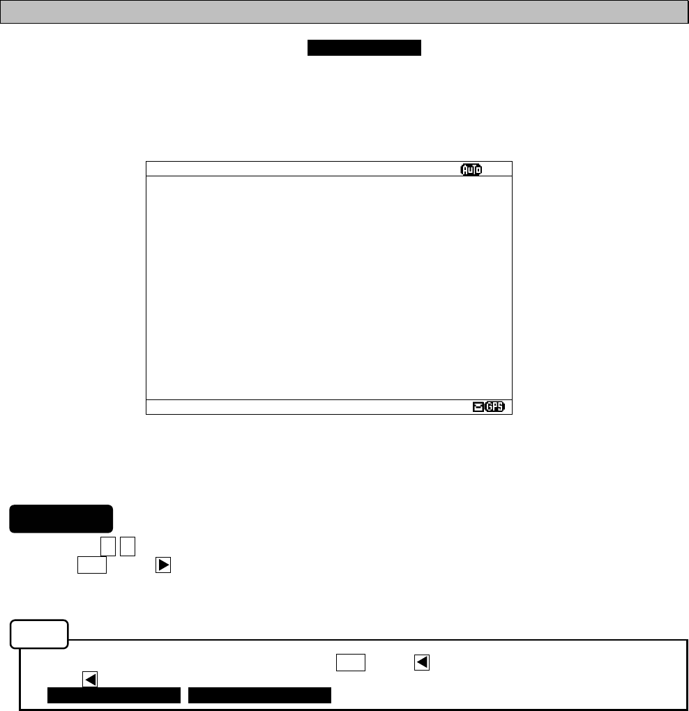
6-42
6.3.5 MAINTENANCE menu (MAINTENANCE)
To display MAINTENANCE menu screen, select 5.MAINTENANCE from MAIN MENU (6.3).
Users can check current status of the system by the menu.
1. Press the ▲ ▼ key to select the menu item.
2. When ENT key or key is pressed, the menu screen of selected item is displayed.
- When cursor is on the item 1-4, cursor moves to the right side of ":"
- When cursor is on the item 5, the menu screen of item 5 appears.
- To return to the MAIN MENU screen, press the CLR key or key.
- If the key is pressed when cursor is on the right side of ":", cursor returns on the item.
(1.CHARACTER SIZE, 2. CER DISP.SETTING, ....)
The outlines of menus are as follows;
1. SELF DIAGNOSIS: Perform self diagnosis test. (See 6.3.4.1)
2. NAVTEX ALARM: Display alarm logs for disorders. (See 6.3.4.2)
3. STATUS: Display current status of NAVTEX setting. (See 6.3.4.3)
4. PORT MONITOR: Display serial data of each port. (See 6.3.4.4)
5. SOFTWARE VERSION:Display versions of software installed in NCR-333. (See 6.3.4.5)
Fig.6-13 MAINTENANCE menu screen
MANINTENANCE
ⅩⅠ
1.SELF DIAGNOSIS
2.NAVTEX ALARM
3.STATUS
4.PORT MONITOR
5.SOFTWARE VERSION
- PROGRAM : 12.34
- LANGUAGE: 21A
- OPTION : ---
Procedures
Notes
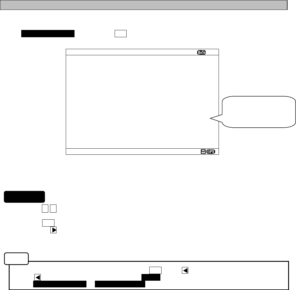
6-43
6.3.5.1 Self diagnosis (SELF DIAGNOSIS)
NCR-333 can be self-diagnosed.
Select 1.SELF DIAGNOSIS, and press the ENT key. SELF DIAGNOSIS screen appears.
1. Press the ▲ ▼ key in order to select the item to diagnose.
2. When the ENT key is pressed, the menu screen of selected item appears.
Pressing the key can display the same.
- When cursor is on the item 1 or 2, cursor moves to the right side of ":"
- When cursor is on the item 3, the menu screen of item 3 appears.
- To return to the MAINTENANCE screen, press the CLR key or key.
- If the key is pressed when cursor is on the “START” of the item 1 or 2, cursor returns on the item 1
or 2. (1.SELF DIAGNOSIS or 2.LCD DIAGNOSIS)
The outlines of menus are as follows;
1. SELF DIAGNOSIS: NCR-333 is diagnosed. (See a))
2. LCD DIAGNOSIS: LCD panel is diagnosed. (See b))
3. SELF DIAGNOSIS LOG: The diagnostic result log of the item 1 is displayed. (See c))
Fig.6-14 SELF DIAGNOSIS screen
SELF DIAGNOSIS
ⅩⅠ
1.SELF DIAGNOSIS : START
ROM : GOOD
RAM : GOOD
SIO : GOOD
PS : GOOD
ANTENNA CHECK : GOOD
518KHZ OVER ALL TEST : GOOD
490KHZ OVER ALL TEST : GOOD
4209.5KHZ OVER ALL TEST: GOOD
(THE QUICK BLOWN FOX JUMPS OVER
THE LAZY DOG.123456789,?/+-:
’
=)
2.LCD DIAGNOSIS :CANCEL
3.SELF DIAGNOSIS LOG
When character size has
selected “LARGE”, these
character strings are not
displayed.
Procudure
Notes
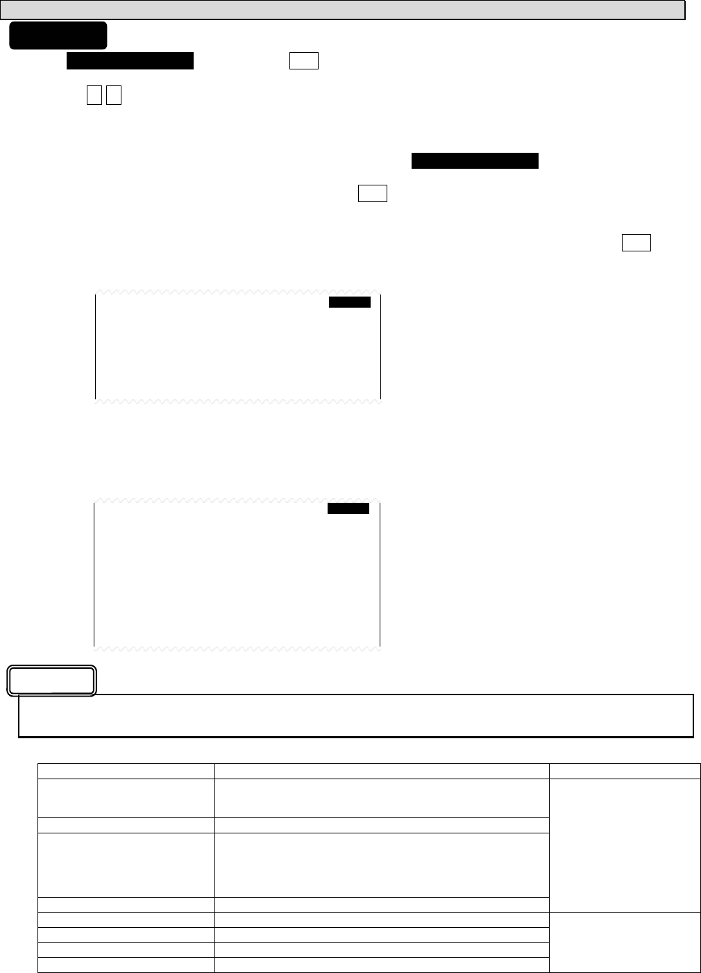
6-44
a. The Diagnosis of equipment (SELF DIAGNOSIS)
1) Select 1.SELF DIAGNOSIS, and press the ENT key. Cursor moves to the right side of ":".
2) Press the ▲ ▼ key and select the following items;
START: Self diagnosis is started. However, the diagnostic results are not printed.
ST-PRTN: Self diagnosis is started. After self diagnosis is completed, the diagnosis results are
printed.
CANCEL: Self diagnosis is not started. Cursor returns to 1.SELF DIAGNOSIS.
3) Select the “START” or “ST-PRTN”, and then press the ENT key.
Self diagnosis starts by the “ROM” test and is ended by the “4209.5 kHz over all test”.
During diagnosis, “SELF DIAGNOSIS” of screen title repeats blink.
The buzzer sounds at the last of diagnosis, and check that the buzzer sounds normally. Press CLR key
to stop the beeping.
“OVER ALL TEST” takes about 15 seconds per test.
Whenever one test (OVER ALL TEST) is completed, character string as shown in the following figure is
displayed. When “*“ is displayed in a character string, the test result is NG.
When the result of the malfunction is displayed, contact our service center or an agency as soon as
possible after referring to troubleshooting of Chapter 7.
The list of diagnosis items
Diagnosis items Explanation Corrective Action
ROM The data memory and the program memory are checked.
When the program memory is abnormal (NG), ‘[1]’ is displayed,
and when the data memory is abnormal, ‘[2]’ is displayed.
RAM The memory for temporarily storage is checked.
SIO Serial interfaces are checked.
When the ‘ECDIS/GPS’ port is abnormal (NG), ‘[1]’ is displayed,
and when the ‘Maintenance/Printer’ port is abnormal, ‘[2]’ is
displayed, and when the ‘DISP’ port is abnormal, ‘[3]’ is
displayed.
PS The power supply part is checked.
Replace CMJ-501N.
ANTENNA CHECK Connection with NAVTEX antenna is checked.
518KHZ OVER ALL TEST Internal receiver (RX1) is checked.
490KHZ OVER ALL TEST Internal receiver (RX2) is checked.
4209.5KHZ OVER ALL TEST Internal receiver (RX3) is checked.
Replace CMN-2333.
1.SELF DIAGNOSIS : START
ROM : GOOD
RAM : GOOD
SIO : GOOD
PS : GOOD
ANTENNA CHECK : GOOD
518KHZ OVER ALL TEST:
490KHZ OVER ALL TEST:
4209.5KHZ OVER ALL TEST:
1.SELF DIAGNOSIS : START
ROM : GOOD
RAM : GOOD
SIO : GOOD
PS : GOOD
ANTENNA CHECK : GOOD
518KHZ OVER ALL TEST: GOOD
490KHZ OVER ALL TEST:
4209.5KHZ OVER ALL TEST:
(THE QUICK BLOWN FOX JUMPS OVER
THE LAZY DOG.123456789,?/+-:
’
=)
Procudure
Caution
OVER ALL TEST:
"OVER ALL TEST" is the test which outputs
a test signal from the inside of the circuit,
and receives the signal from each receiver.
Test signal (Character strings):
THE QUICK BLOWN FOX JUMPS OVER
THE LAZY DOG. 123456789,?/+-:’=
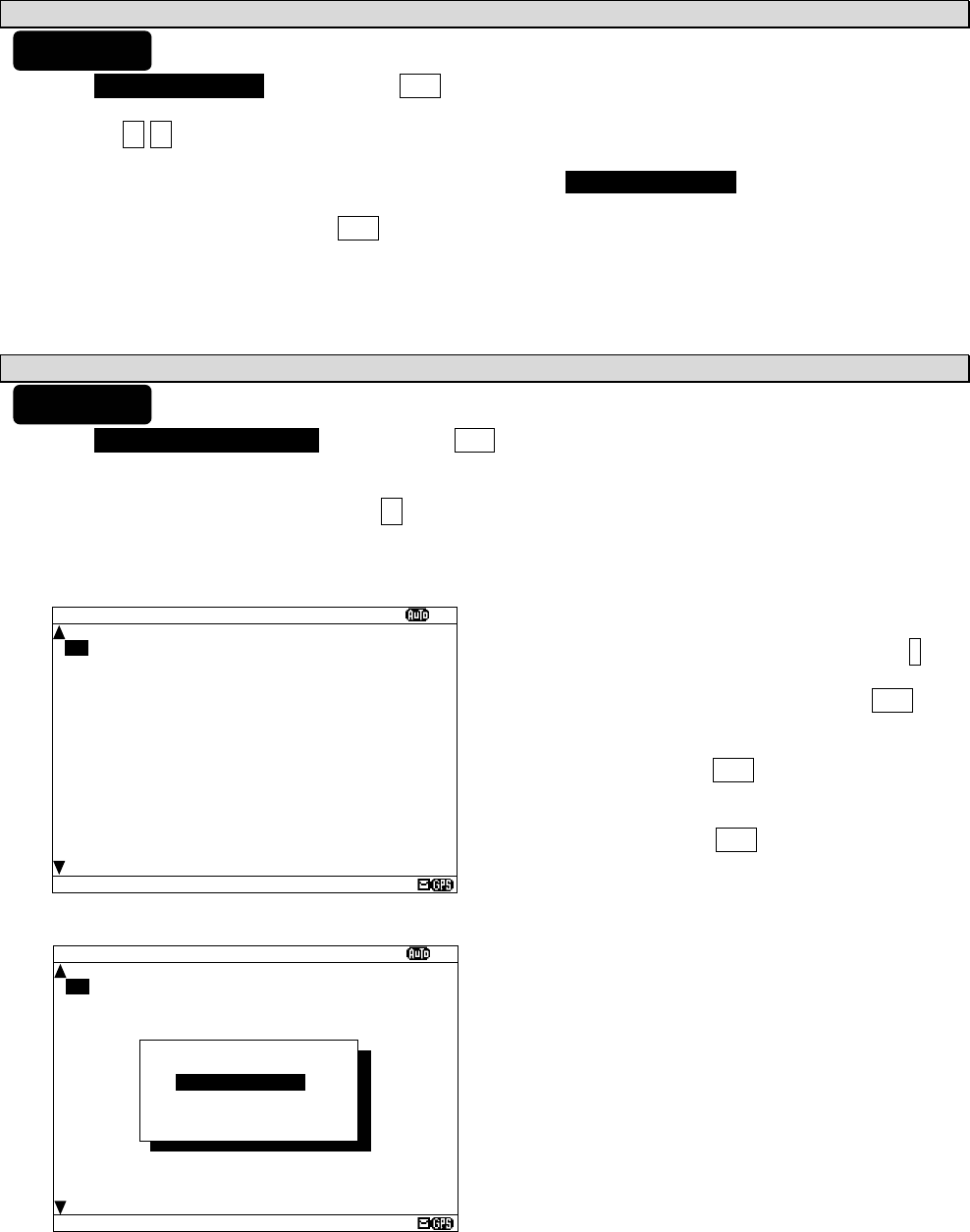
6-45
SELF DIAGNOSIS LOG
ⅩⅠ
9.RESULT 29/06/05 12:34
ROM[1][2] :NG
RAM :GOOD
SIO[1][2][3] :NG
PS :GOOD
ANTENNA CHECK :GOOD
518KHZ OVER ALL TEST:GOOD
490KHZ OVER ALL TEST:GOOD
4209.5KHZ OVER ALL TEST:GOOD
b. The diagnosis of LCD panel (LCD DIAGNOSIS)
1) Select 2.LCD DIAGNOSIS, and press the ENT key. Cursor moves to the right side of ":".
2) Press the ▲ ▼ key and select the following items;
START: Diagnosis is started.
CANCEL: Diagnosis is canceled, and cursor returns to 2.LCD DIAGNOSIS.
3) Select the “START”, and press the ENT key.
This diagnosis blinks the viewing area (White -> Black -> White-> ...).
c. Self diagnosis log (SELF DIAGNOSIS LOG)
1) Select 3.SELF DIAGNOSIS LOG, and press the ENT key. SELF DIAGNOSIS LOG screen appears.
The newest result is displayed on this screen.
2) To display the next old result, press the ▼ key. (Up to last 10 results)
The diagnosed time is displayed when external GPS receiver is connected.
”--/--/-- --:--“ is displayed when time is not able to be acquired. (External GPS receiver is not connected.)
To print a result to the external printer, press the * key
in order to display the sub screen.
Select the “[PRINT OUT]”, and press the ENT key.
Printing is started.
To stop printing, press the CLR key while printing.
To return to the SELF DIAGNOSIS screen, select the
“[CANCEL]” and press the ENT key.
SELF DIAGNOSIS LOG
ⅩⅠ
9.RESULT 29/06/05 12:34
ROM[1][2] :NG
RAM :GOOD
SIO[1][2][3] :NG
PS :GOOD
ANTENNA CHECK :GOOD
518KHZ OVER ALL TEST:GOOD
490KHZ OVER ALL TEST:GOOD
4209.5KHZ OVER ALL TEST:GOOD
*DIAGNOSIS LOG*
[PRINT OUT]
[CANCEL]
Procudure
Procudure
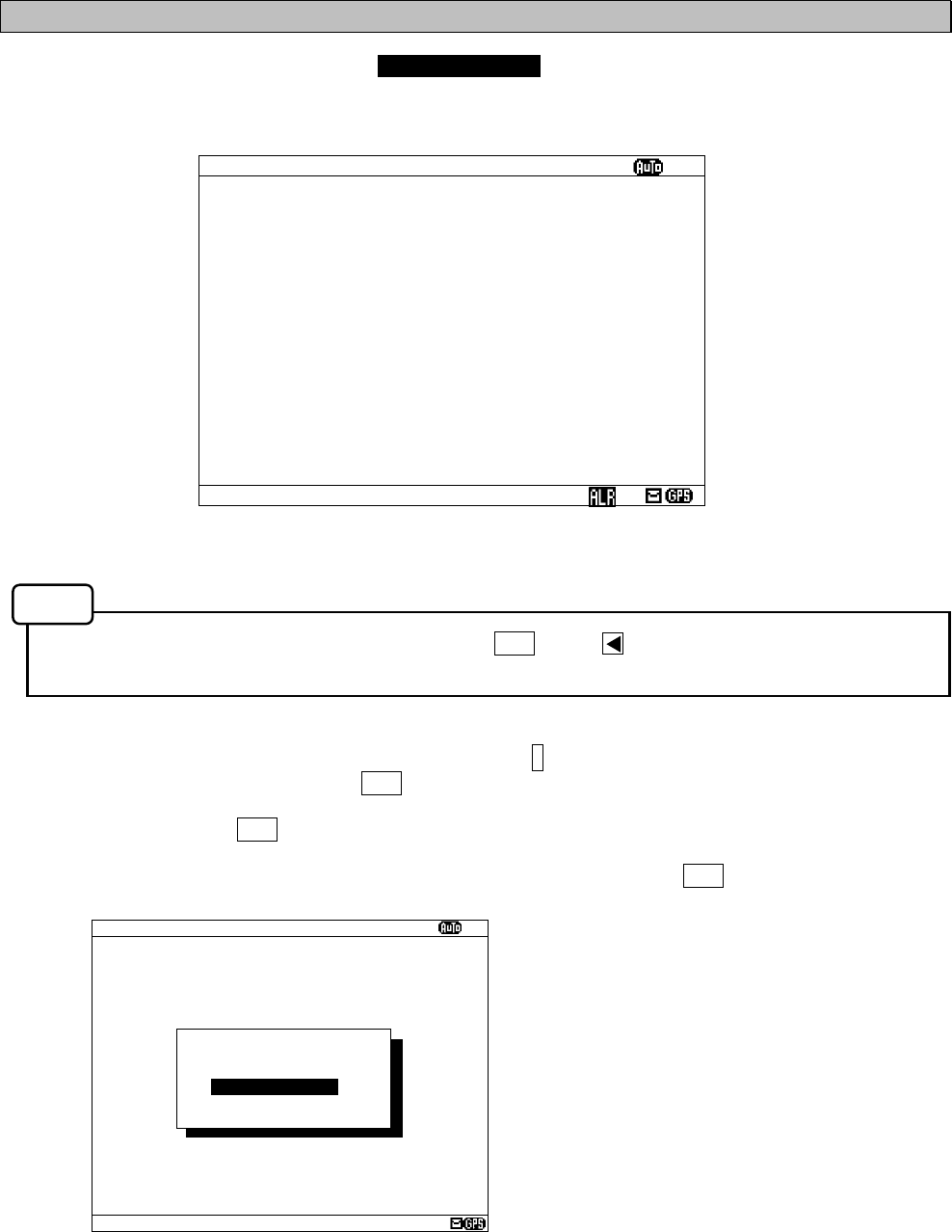
6-46
6.3.5.2 NAVTEX alarms (NAVTEX ALARM)
To display NAVTEX ALARM screen, select 2.NAVTEX ALARM from MAINTENANCE menu (6.3.5).
In the NAVTEX ALARM screen, the present alarm is displayed.
On the ALARM HISTORY screen, the alarm which occurred in operation can be displayed from the latest one
to a maximum of 20 affairs.
- To return to the MAINTENANCE screen, press the CLR key or key.
- "NO DATA" is displayed when NAVTEX alarm has not occurred.
To print the NAVTEX alarms to the external printer, press the * key in order to display the sub screen.
Select the “[PRINT OUT]”, and press the ENT key. Printing is started.
To stop printing, press the CLR key while printing.
To return to the NAVTEX ALARM screen, select the “[CANCEL]” and press the ENT key.
Fig.6-15 NAVTEX ALARM screen
NAVTEX ALARM
ⅩⅠ
11/12/05 15:34
054,A,Printer err
*NAVTEX ALARM*
[HISTORY]
[PRINT OUT]
[CANCEL]
NAVTEX ALARM
ⅩⅠ
11/12/05 15:34
054,A,Printer err
Notes
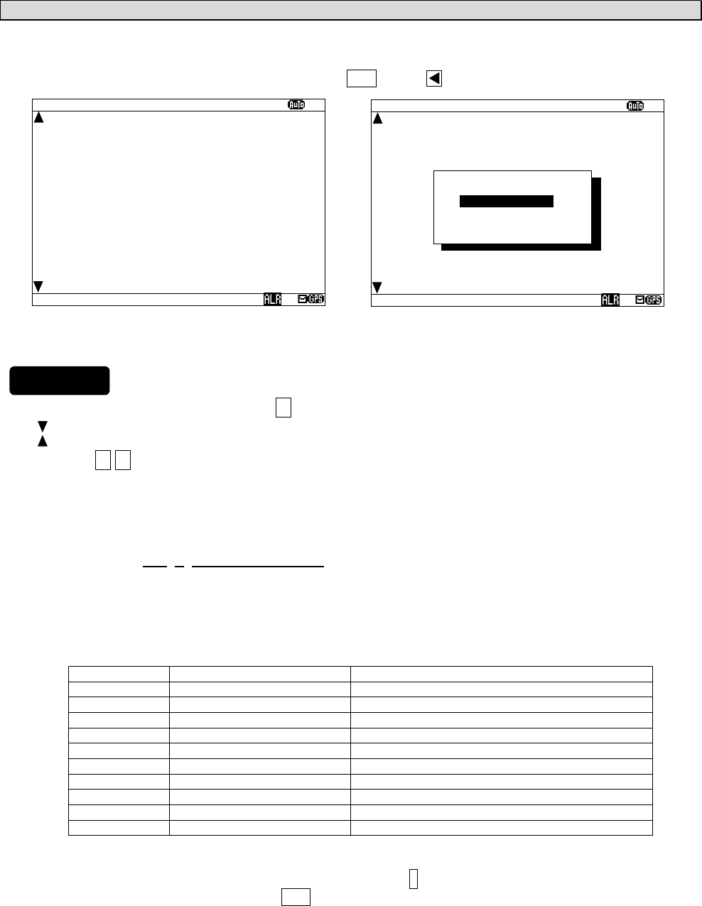
6-47
a. Alarm history (ALARM HISTORY)
This screen displays a history of alarms which occur while the power is on. It displays the alarm history
from the most recent one maximum 20 lines.
To return to the NAVTEX ALARM screen, press the CLR key or key.
1) To display the next old result, press the ▼ key.
- “ “ mark is displayed on the bottom line when the alarm history screen is able to scroll downward.
- “ “ mark is displayed on the top line when the alarm history screen is able to scroll upward.
- Press the ▲ ▼ key and scroll the viewing area.
The time of an alarm occurred and is restored is displayed when external GPS receiver is connected.
”--/--/-- --:--“ is displayed when time is not able to be acquired. (External GPS receiver is not connected.)
The display of the alarm is described.
Alarm message: 001, V, antenna malfufnction
1 2 3
1: The alarm number (refer to the following table)
2: The alarm condition -> “V”: Healthy status, “A”: Alarm is occurring
3: Alarm’s description text (refer to the following table)
The list of NAVTEX alarm
Alarm No. Alarm’s description text The contents of unusual detection
002 Receiver 1 malfunction Unusual detection at the RX1
003 Receiver 2 malfunction Unusual detection at the RX2
004 Receiver 3 malfunction Unusual detection at the RX3
005 General failure Unusual detection at the power supply part
006 Built in self test failure Self diagnosis failure
051 Antenna malfunction Unusual detection of antenna connection
052 Flash memory error The data in a memory is broken.
053 Rx unit modem error Unusual detection at the modem part
054 Printer error External printer has malfunction
055 EXT SIO output error Unusual detection at the “DISP” output port
2) To print the NAVTEX alarms to the external printer, press the * key in order to display the sub screen.
Select the “[PRINT OUT]”, and press the ENT key. Printing is started.
[PRINT OUT]: Printing is started.
[CANCEL]: Diagnosis is canceled, and the sub screen is closed.
Fig.6-16 ALARM HISTORY screen
NAVTEX ALARM
ⅩⅠ
3.11/12/04 15:30 001 A
antenna malfunction
4.11/12/04 15:30 002 A
power supply error
5.02/11/04 02:31 001 V
antenna malfunction
6.02/11/04 02:19 001 A
antenna malfunction
7.23/09/04 22:15 001 V
antenna malfunction
8.23/09/04 22:15 002 V
power supply error
9.23/09/04 22:14 002 A
power supply error
10.23/09/04 22:13 001 A
antenna malfunction
*NAVTEX ALARM*
[PRINT OUT]
[CANCEL]
NAVTEX ALARM
ⅩⅠ
3.11/12/04 15:30 001 A
antenna malfunction
4.11/12/04 15:30 002 A
power supply error
5.02/11/04 02:31 001 V
antenna malfunction
6.02/11/04 02:19 001 A
antenna malfunction
7.23/09/04 22:15 001 V
antenna malfunction
8.23/09/04 22:15 002 V
power supply error
9.23/09/04 22:14 002 A
power supply error
10.23/09/04 22:13 001 A
antenna malfunction
Procudure
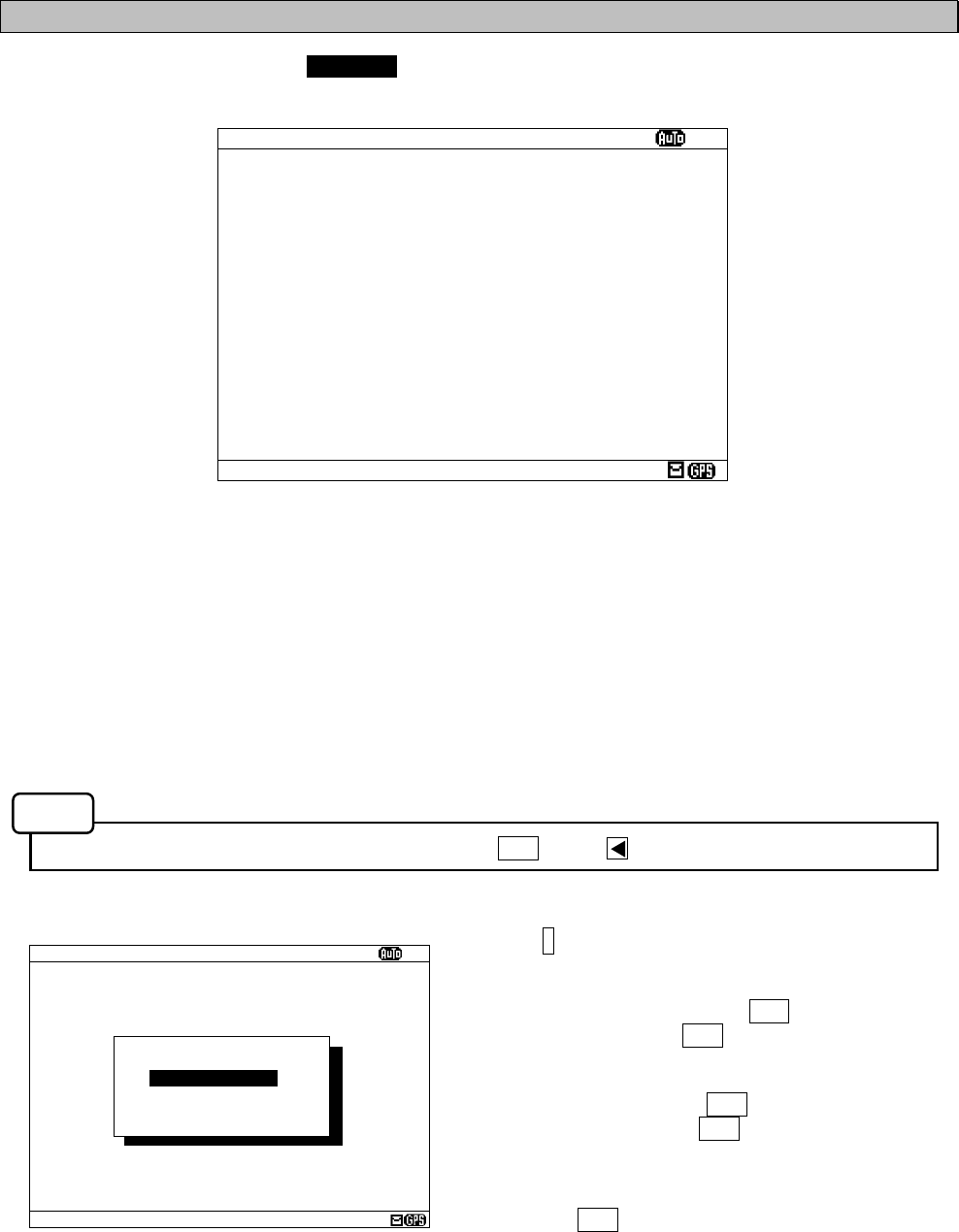
6-48
6.3.5.3 Setting status of the NAVTEX Receiver (STATUS)
To display STATUS screen, select 3.STATUS from MAINTENANCE menu (6.3.5).
The setting information of NCR-333 is displayed on the screen.
The setting information of each items are as follows;
- 518 (490, 4209.5) kHz DISABLED AREA: The alphabet of stations which does not receive is displayed.
- 518 (490, 4209.5) kHz DISABLED MESSAGE TYPE:
The alphabet of message type which does not receive is displayed.
- N OF STORED MSG: The number of the stored messages is displayed. Starting from the left, 518k,
490k, and 4209.5 kHz are displayed. When the number of the stored messages
is the maximum, it is displayed as “FULL”.
- N OF SAVE MSG: The number of the saved messages is displayed. Starting from the left, 518k,
490k, and 4209.5 kHz are displayed. When the number of the saved messages
is the maximum, it is displayed as “FULL”.
- To return to the MAINTENANCE screen, press the CLR key or key.
Press the * key in order to display the sub screen.
To print the setting status to the external printer, select
the “[PRINT OUT]”, and press the ENT key.
To stop printing, press the CLR key while printing.
To output the status data to serial ports, select the
“[DATA OUT]”, and press the ENT key.
To stop outputting press the CLR key while data
outputting.
To return to the STATUS screen, select the “[CANCEL]”
and press the ENT key.
Fig.6-17 STATUS screen
STATUS
ⅩⅠ
NAVAREA:
ⅩⅠ
518KHZ DISABLED AREA:
A--D-----J----OPQR--------
490KHZ DISABLED AREA:
---------J-------------XYZ
4209.5KHZ DISABLED AREA:
---D----------OPQR--------
518KHZ DISABLED MESSAGE TYPE:
-----EF-----MNOPQR--------
490KHZ DISABLED MESSAGE TYPE:
-----EF-----MNOPQR--------
4209.5KHZ DISABLED MESSAGE TYPE:
-----EF-----MNOPQR--------
N OF STORED MSG: 94: 52: 22
N OF SAVE MSG: 39: 21: 5
NAVTEX ALARM
ⅩⅠ
NAVAREA:
ⅩⅠ
518KHZ DISABLED AREA:
A
—
D-----J----OPQR--------
490KHZ DISABLED AREA:
---------J-------------XYZ
4209.5KHZ DISABLED AREA:
---D----------OPQR--------
518KHZ DISABLED MESSAGE TYPE:
-----EF-----MNOPQR--------
490KHZ DISABLED MESSAGE TYPE:
-----EF-----MNOPQR--------
4209.5KHZ DISABLED MESSAGE TYPE:
-----EF-----MNOPQR--------
N OF STORED MSG: 94: 52: 100
N OF SAVE MSG: 39: 40:FULL
*STATUS*
[PRINT OUT]
[DATA OUT]
[CANCEL]
Notes
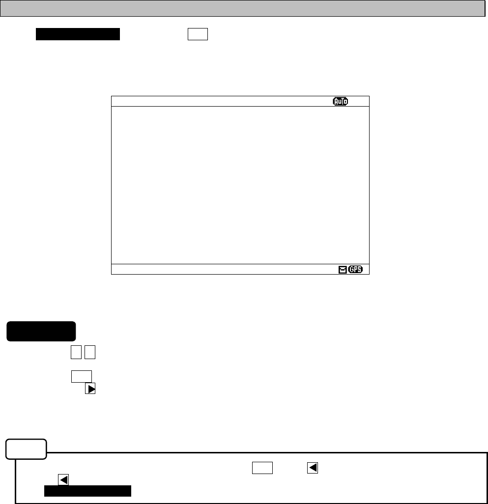
6-49
6.3.5.4 Port monitor (PORT MONITOR)
Select 4.PORT MONITOR, and press the ENT key. PORT MONITOR screen appears.
Select the port for monitoring. It can check whether data is normally outputted from the port.
In addition, the displayed data can be stored temporarily to be rechecked.
1. Press the ▲ ▼ key in order to select the items.
2. When the ENT key is pressed, the menu screen of selected item appears.
Pressing the key can display the same.
- When cursor is on the item 1, cursor moves to the right side of ":"
- When cursor is on the item 2, the menu screen of item 2 appears.
- To return to the MAINTENANCE screen, press the CLR key or key.
- If the key is pressed when cursor is on the right side of ":" of the item 1, cursor returns on the item
1. (1.PORT SELCTION)
The outlines of menus are as follows;
1. PORT SELECTION: Select the port to check the serial in/output data. (See a. The check of
in/output data)
2. PORT LOG: The data stored temporarily is displayed. (See c. Port log)
Fig.6-18 PORT MONITOR screen
PORT MONITOR
ⅩⅠ
1.PORT SELECTION: OFF
2.PORT LOG
Notes
Procudure
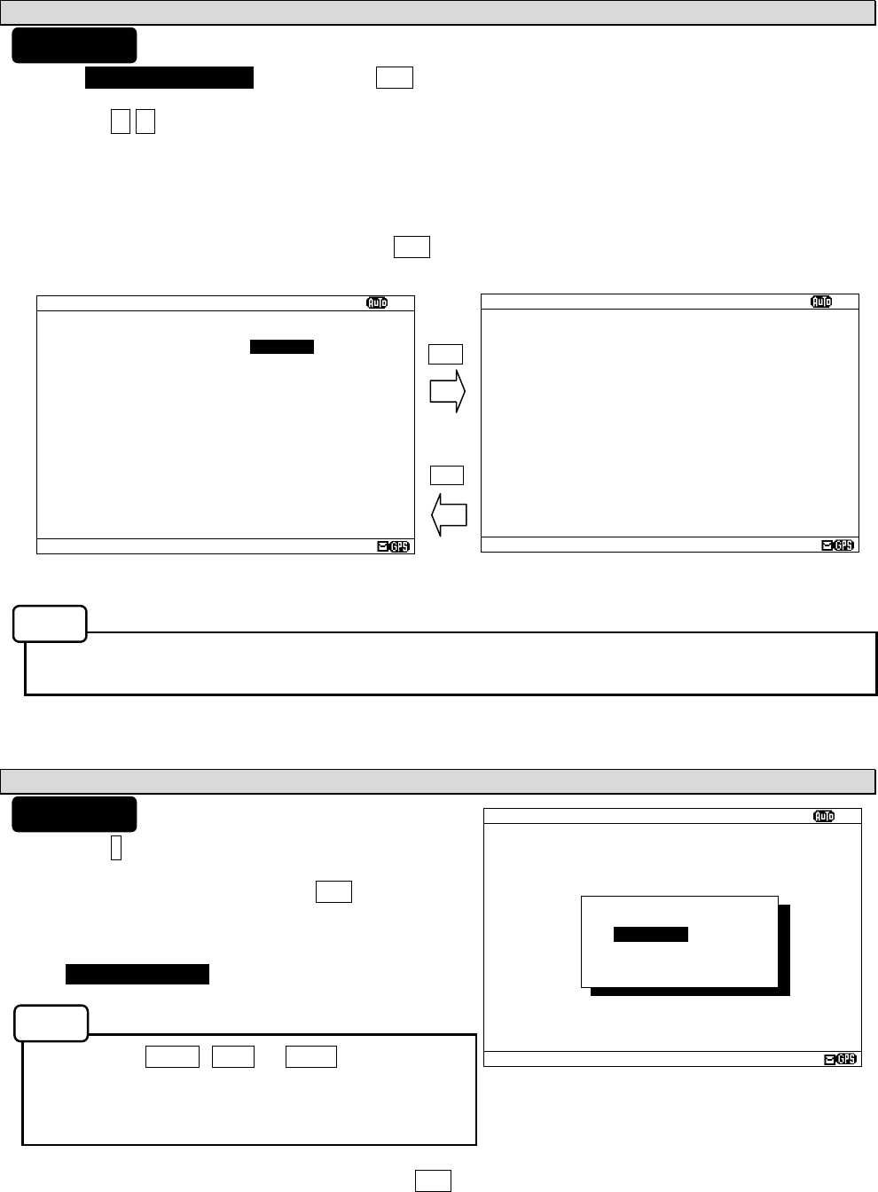
6-50
PORT MONITOR
ⅩⅠ
$PRMC,012601.00,A,3541.273,N,1393
4.251,E,00.0,158.,020903,00.,W,D*2
D
$GPGLL,3541.273,N,13934.251,E,0126
01.0
$GPGGA,012602.00,3541.273,N,13934.
251,E,2,08,01.0,+0050,M,+039,M,05,
,0686*5C
$PRMC,012601.00,A,3541.273,N,1393
4.251,E,00.0,158.,020903,00.,W,D*2
D
$GPGLL,3541.273,N,13934.251,E,0126
01.0
$GPGGA,012602.00,3541.273,N,13934.
251,E,2,08,01.0,+0050,M,+039,M,05,
,0686*5C
PORT MONITOR
ⅩⅠ
1.
PORT MONITOR: GPS IN
2. PORT LOG
a. The check of in/output data (PORT SELECTION)
1) Select 1.PORT SELECTION, and press the ENT key. Cursor moves to the right side of ":".
2) Press the ▲ ▼ key and select the following items;
OFF: The monitoring of each port does not carry out.
GPS IN: Input data of the GPS port
DISP IN: Input data of the DISP (Option) port
DISP OUT: Output data of the DISP (Option) port
3) Example - Select the “GPS IN”, and press the ENT key.
PORT MONITOR menu screen changes to the data display screen.
- When neither the GPS receiver nor MPD is connected to the port of “GPS IN” and “DISP IN”, nothing is
displayed on the data display screen.
b. Store the displaying data temporarily
1) Press the * key. The sub screen appears.
2) Select the “[START]”, and press the ENT key. Storing of
the displaying data is started.
During storing, the following is displayed on the screen
title.
“ NOW LOGGING... “
- When the MENU, DISP or USER key is pressed,
storing of the displaying data is stopped.
- Data is recordable to two screens.
- Data is stored until it turns off the power.
3) For canceling, select the “[STOP]” and press the ENT key.
The sub screen is closed, and storing of the displaying data is stopped.
ENT
CLR
PORT MONITOR
ⅩⅠ
$PRMC,012601.00,A,3541.273,N,1393
4.251,E,00.0,158.,020903,00.,W,D*2
D
$GPGLL,3541.273,N,13934.251,E,0126
01.0
$GPGGA,012602.00,3541.273,N,13934.
251,E,2,08,01.0,+0050,M,+039,M,05,
,0686*5C
$PRMC,012601.00,A,3541.273,N,1393
4.251,E,00.0,158.,020903,00.,W,D*2
D
$GPGLL,3541.273,N,13934.251,E,0126
01.0
$GPGGA,012602.00,3541.273,N,13934.
251,E,2,08,01.0,+0050,M,+039,M,05,
,0686*5C
*PORT MONITOR*
[START]
[STOP]
Procudure
Procudure
Notes
Notes
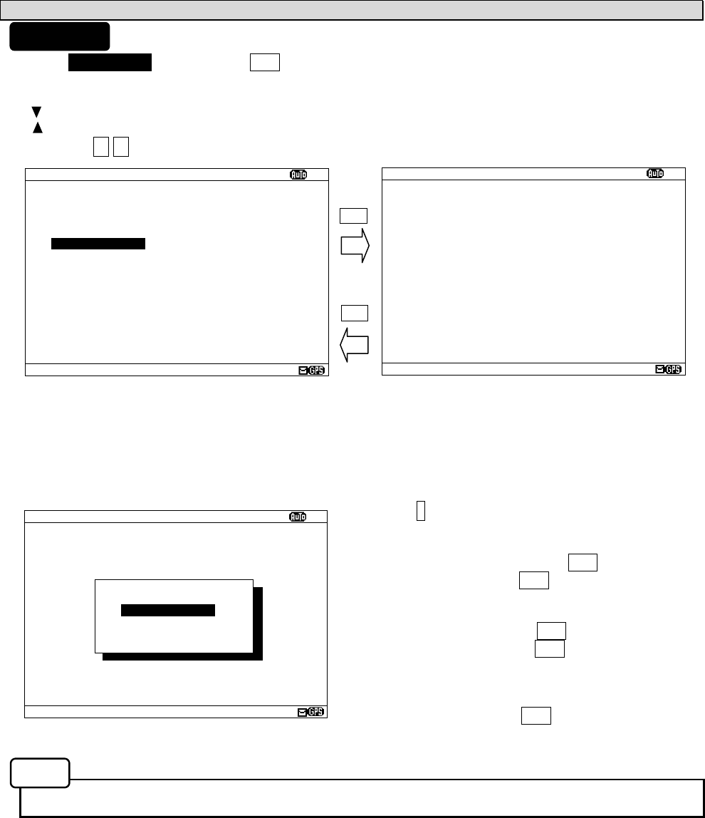
6-51
PORT LOG
ⅩⅠ
$PRMC,012601.00,A,3541.273,N,1393
4.251,E,00.0,158.,020903,00.,W,D*2
D
$GPGLL,3541.273,N,13934.251,E,0126
01.0
$GPGGA,012602.00,3541.273,N,13934.
251,E,2,08,01.0,+0050,M,+039,M,05,
,0686*5C
$PRMC,012601.00,A,3541.273,N,1393
4.251,E,00.0,158.,020903,00.,W,D*2
D
$GPGLL,3541.273,N,13934.251,E,0126
01.0
$GPGGA,012602.00,3541.273,N,13934.
251,E,2,08,01.0,+0050,M,+039,M,05,
,0686*5C
PORT LOG
ⅩⅠ
1.PORT MONITOR: GPS IN
2. PORT LOG
c. Port log(PORT LOG)
1) Select 2.PORT LOG, and press the ENT key. PORT LOG screen appears.
The data stored in the PORT MONITOR is displayed on this screen.
2) “ “ mark is displayed on the bottom line when the PORT LOG screen is able to scroll downward.
- “ “ mark is displayed on the top line when the PORT LOG screen is able to scroll upward.
Press the ▲ ▼ key and scroll the viewing area.
Press the * key. The sub screen appears.
To print the setting status to the external printer, select
the “[PRINT OUT]”, and press the ENT key.
To stop printing, press the CLR key while printing.
To output the status data to serial ports, select the
“[DATA OUT]”, and press the ENT key.
To stop outputting, press the CLR key while data
outputting.
To return to the PORT LOG screen, select the
“[CANCEL]” and press the ENT key.
- All the character strings displayed on the PORT LOG screen are printed.
ENT
CLR
PORT LOG
ⅩⅠ
$PRMC,012601.00,A,3541.273,N,1393
4.251,E,00.0,158.,020903,00.,W,D*2
D
$GPGLL,3541.273,N,13934.251,E,0126
01.0
$GPGGA,012602.00,3541.273,N,13934.
251,E,2,08,01.0,+0050,M,+039,M,05,
,0686*5C
$PRMC,012601.00,A,3541.273,N,1393
4.251,E,00.0,158.,020903,00.,W,D*2
D
$GPGLL,3541.273,N,13934.251,E,0126
01.0
$GPGGA,012602.00,3541.273,N,13934.
251,E,2,08,01.0,+0050,M,+039,M,05,
,0686*5C
*PORT LOG*
[PRINT OUT]
[DATA OUT]
[CANCEL]
Procudure
Notes
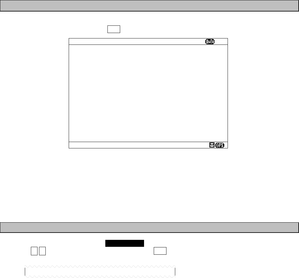
6-52
6.3.5.5 Software version (SOFTWARE VERSION)
When MAINTENANCE menu screen is displayed, the present software version is displayed on the item 5.
To display the MAIN MENU, press the CLR key.
The explanations of each item are as follows;
- PROGRAM: Program version is displayed.
- LANGUAGE: Langage version is displayed.
- OPTION: Option langage version is displayed.
When the option language is not installed, ”---“ is displayed.
6.3.6 The display language setting (LANGUAGE)
To select the display language, select 6.LANGUAGE from MAIN MENU (6.3).
Press the ▲ ▼ key and select the language. When the ENT key is pressed, menu screens are displayed in
the selected language.
When the language data is already installed, the language name is displayed as follows.
- FRENCH
- PORTUGUESE
- ITALIAN
- SPANISH
When the option language is already installed, the option language name is displayed.
The initial setting is “ENGLISH”.
Fig.6-19 Maintenance manu screen
MANINTENANCE
ⅩⅠ
1.SELF DIAGNOSIS
2.NAVTEX ALARM
3.STATUS
4.PORT MONITOR
5.SOFTWARE VERSION
- PROGRAM : 12.34
- LANGUAGE: 21A
- OPTION : ---
6.LANGUAGE: ENGLISH
7-1
7. MAINTENANCE AND INSPECTION
The performance and longevity of this equipment depend on careful maintenance. To maintain
the best performance, the following periodic inspections are highly recommended.
CAUTION
Keep the power supply voltage within the specified value (10.8 - 35Vdc).
Know the condition of normal status when the equipment is properly functioning.
Keep comparing the current status to the normal status to immediately detect any
malfunctions.
Do not attempt to inspect or repair the inside of this equipment with the
exception of qualified service personnel, as doing so may cause fire, electric
shock or malfunction. If any malfunctions are detected, contact our service
center or agents.
Use only specified fuses.
The use of other fuse may cause fire and/or damage.
The fuses are used for NBG-319 or NBG-320.
The power switch on the power distribution panel must be turned off during
replacing a fuse. Remove the cap of the front panel, and then exchange
fuses.
7. 1 General Maintenance and Inspection
Below are listed general maintaining and inspecting items, which can be done with usual tools
and apparatus.
No. Item Maintenance and inspection
1 Cleaning
Gently clean the surface of the panel, switches, and cover with soft cloth or
silicon oil. No oil is needed because this unit has no moving mechanisms
inside.
2 Looseness
of parts
Inspect for looseness and correctly tighten the following:
Screws, nuts and connectors.
WARNING
7-2
7. 2 Periodic Inspection
Regarding the functions for performing self-diagnosis and monitoring the system status, please
refer to “6.3.5 Maintenance Menu”
7.2.1 Confirming the RX station and Message type
To check the receiving station and message type, please refer to 6.1.3 and 6.3.2. Be sure to set
up the receiving station and message type correctly.
7.2.2 Confirming the Alarm Status
With referring 6.3.5.2, confirm that failure alarm is not occurring. If any alarm occurs, check the
cause of the alarm. NCR-333 Alarm Table is followings.
NCR-333 Alarm Table
Failure alarm list (ALR sentence output)
Alarm
No.
Indication Alarm Occurrence Conditions
005
006
General failure
Built in self test failure
After carrying out self-diagnosis, NCR-333 detected
that the input voltage was abnormal.
006
051
Built in self test failure
Antenna malfunction
After carrying out self-diagnosis, NCR-333 detected
that the output voltage of antenna terminal was low
voltage.
002
006
Receiver 1 malfunction
Built in self test failure
After carrying out self-diagnosis, NCR-333 detected
that the receiver 1 (518kHz) could not receive
because of abnormalities.
003
006
Receiver 2 malfunction
Built in self test failure
After carrying out self-diagnosis, NCR-333 detected
that the receiver 2 (490kHz) could not receive
because of abnormalities.
004
006
Receiver 3 malfunction
Built in self test failure
After carrying out self-diagnosis, NCR-333 detected
that the receiver 3 (4209.5kHz) could not receive
because of abnormalities.
002
053
Receiver 1 malfunction
Rx unit modem error
The receiver 1 (518kHz) could not receive because
of internal MODEM failure.
003
053
Receiver 2 malfunction
Rx unit modem error
The receiver 2 (490kHz) could not receive because
of internal MODEM failure.
004
053
Receiver 3 malfunction
Rx unit modem error
The receiver 3 (4209.5kHz) could not receive
because of internal MODEM failure.
051 Antenna malfunction The output voltage of antenna terminal is low
voltage.
005 General failure The input voltage is low level.
054 Printer error External printer is abnormal.
055 EXT SIO output error “DISP” output port is abnormal.
7-3
7. 3 Trouble Shootings
7.3.1 Trouble Shootings
For reference, this section presents a troubleshooting guideline for finding defective sections.
Symptom of Error Possible Cause or Cause of Fault Countermeasures
Power is not distributed from the
inboard distribution panel.
Supply power from the distribution
panel.
Power is not supplied from the
power supply unit or NCR-333.
Check that the wiring of the power
unit is correct.
Check that the output voltage of the
power unit or NCR-333 is correct.
Power that the power unit supplies
is out of range.
Replace the power unit.
The fuses in the Power Supply Unit
(Option) are blown out.
Check that the wiring is correct and
replace the fuses.
The power supply cable is broken. Replace the power supply cable.
Power is not supplied
when the power switch
is pressed.
The controller switch is broken. Replace the CMD-953 circuit board.
The LCD malfunctions. Replace the LCD. Some dots are missing
on the LCD. The control unit malfunctions. Replace the CMJ-501N circuit
board.
The buzzer malfunctions. Replace the CMD-953 circuit board.No alarming sound is
generated.
The control unit malfunctions. Replace the CMJ-501N circuit
board.
The control unit malfunctions. Replace the CMJ-501N circuit
board.
The illumination does
not light.
The LCD malfunctions. Replace the LCD.
The polarity or antenna cable is
incorrect.
Check if the polarity is correct and
connect it.
Neither the receiving station nor the
message type is selected correctly.
Refer to “6.3.1” or “6.3.2”.
The NAVTEX antenna (NAW-333)
is damaged.
Replace the NAW-333.
No NAVTEX message
is received.
The following alarm number
appears: 002, 003, or 004.
Internal receiver 1, 2 or 3 is broken.
Replace the CMN-2333.
The polarity of the serial cable is
incorrect.
Check if the polarity is correct and
connect it.
The interface between the sensor
and NCR-333 is incorrect.
Check if the interface is correct
before its connection.
The sentence that the sensor
generates is not supported by the
NCR-333.
Check the output command and the
version.
The serial format (baud rate, etc.)
does not meet the setting of the
controller.
Check the serial format of the
sensor.
The sensor (GPS, gyro, rate-of-turn
indicator) malfunctions.
Replace the sensor.
Sensor data (external
GPS, gyro, and
rate-of-turn) cannot be
loaded.
Do not attempt to inspect or repair the inside of this equipment with the
exception of qualified service personnel, as doing so may cause fire, electric
shock or malfunction. If any malfunctions are detected, contact our service
center or agents.
WARNING
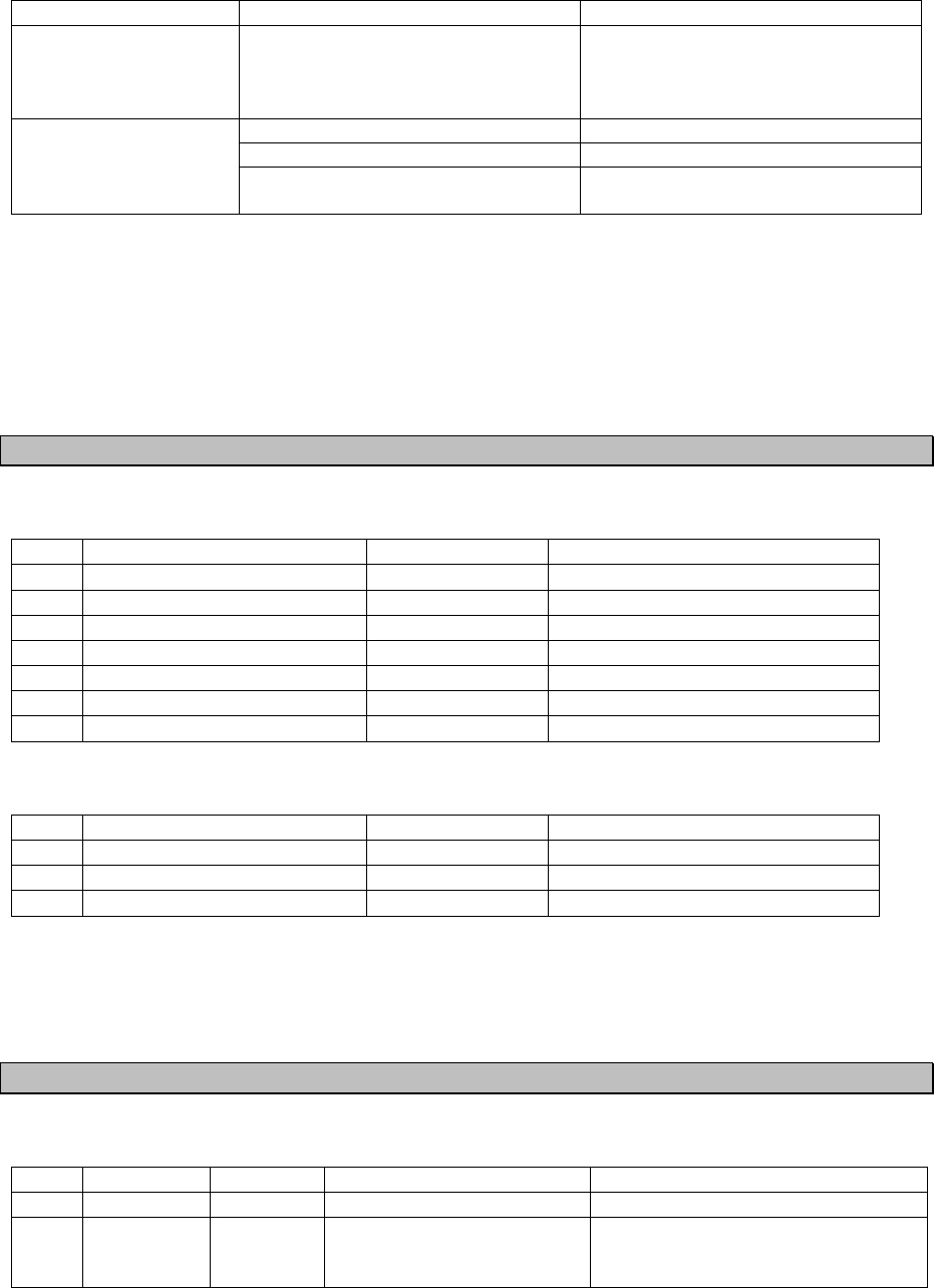
7-4
Symptom of Error Possible Cause or Cause of Fault Countermeasures
Sensor data (external
GPS, gyro, and
rate-of-turn) cannot be
loaded.
The DPU (CMJ-501N) malfunctions. Replace the CMJ-501N circuit
board.
The external printer is not ON. Turn on the external printer.
The printer power is not turned on. Check the printer power cable.
The external printer
does not print
Printer property (printer settings) is
incorrect.
Refer to “6.3.4.5”.
7.3.2 Maintenance Units
Maintenance units for repair are followings.
No. Unit Name Model Note
1 RX UNIT CMN-2333
2 DPU CMJ-501N
3 KEYBOARD UNIT CMD-953
4 NAVTEX ANTENNA NAW-333-1 ANTENNA for NCR-333
5 POWER SUPPLY UNIT NBG-319 DC: +12/24Vdc
6 POWER SUPPLY UNIT NBG-320 AC: 110/220Vac, DC: +12/24Vdc
7 Whip Antenna 5ABBE00001 0.6 m
Fuses
No. Unit Name Model Note
1 5A Fuse ULTSC 5A N1 For NBG-319
2 2A Fuse MQ4 250V 2A For NBG-320
3 4A Fuse MQ2 125V 4A For NBG-320
7.3.3 Spear parts for periodic maintenance
Spear parts for periodic maintenance are followings.
No. Unit Name Code Decline period Note
1 LCD Unit CCN-392 40,000 hours 5 years in continuous operation
2 Printer
(Option) DPU-414 Approx. 500,000 lines
When the thermal paper of 25m roll
length is used, about 90 thermal
papers can be used.

8-1
8. AFTER-SALES SERVICE
Warranty
z Warranty period is one year from the purchase day.
Warranty
z Keeping period of maintenance parts is ten years from the production is discontinued.
Before returning repair
If what appears to be a malfunction is detected, refer to “7.3 Troubleshooting” to check if the
equipment is actually defective before requesting repair.
If the defect persists, immediately stop operation and call our service center or agents.
z During the warranty period, our agencies or we will repair the malfunction without any fee,
according to the specified procedure.
z After the warranty expires, we will repair the malfunction for a fee, if repair is possible. In this case,
send the parts or we’ll repair onboard in a specified port. The parts may be repaired in a plant if it’s
unrepairable onboard.
z Item for notification
Product name, type, manufactured data, serial number,
information about the malfunction (the more detailed, the better),
information about the alarm number and software version,
your company or organization name, address and phone number.
Periodical maintenance recommendation
Performance of this equipment may degrade over time because parts wear out, although degradation
depends on how this unit has been maintained.
We recommend periodic professional maintenance checks in addition to daily maintenance.
Call our service center or agents for periodic professional maintenance (This maintenance requires a
service charge).
Call our office or the nearest agency for detailed information about after-sales service.
[JRC offices or the nearest agency]
See the List of JRC offices or the nearest agency at the end of this manual.

8-2
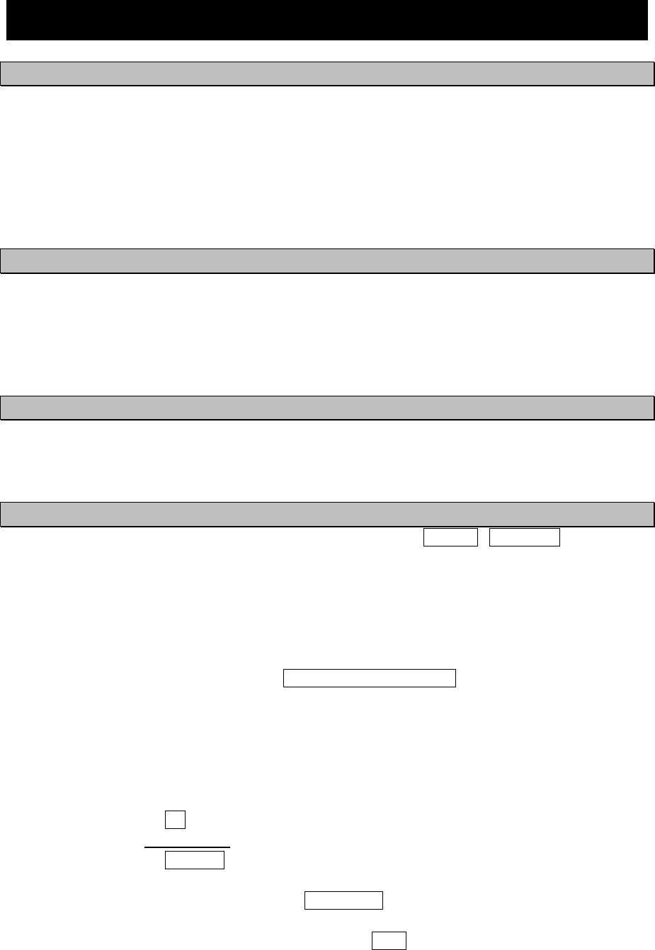
9-1
9. SPECIFICATIONS
9.1 NAVTEX RECEIVER (NCR-333)
9.1.1 Receiver
(1) Receiving frequency : 518kHz, 490kHz and 4209.5kHz
(2) Receiving modulation : F1B
(3) Sensitivity : CER ≦ 1x10⁻² at 1uV (CER: Character Error Rate)
(4) Antenna input : 50 ohms for NAVTEX antenna
50 ohms for wide-band antenna
High impedance for wire antenna
9.1.2 Operation panel
(1) Type of display : 5.7-inch FSTN LCD, 320×240 dots
(2) Key board : 12 keys
(3) Back-light : For LCD and key board
(4) Dimmer control : Bright, medium1, medium2, off (Selectable from keyboard)
9.1.3 Power supply
(1) Input voltage : 12 / 24Vdc (+30%, -10%)
(2) Power consumption : 9 W (at 24 Vdc input)
9.1.4 External interfaces
(1) INS (Integrated Navigation System) communication ports DATA IN / DATA OUT
One communication port meets the requirements of IEC 61162-1
- Baudrate : 4800bps
- Data bit : 8bits
- Parity : none
- Stop bit : 1bit
- Flow control : none
(2) External printer / maintenance port PRINTER/MAINTENANCE
One communication port meets the requirements of RS-232C (D-sub 9pin).
- Baudrate : User setting (4800 / 9600 / 38.4k bps)
- Data bit : 8bits
- Parity : none
- Stop bit : 1bit
- Flow control : User setting (Hard / None)
(3) Relay terminals BK
One port for Break in relay signal
(4) Relay terminals EXT ALR
One port for external alarm device
(5) Remote maintenance data output port DATA OUT2
One output port meets the requirements of IEC 61162-1
(6) MPD (Multi purpose display) communication port DISP
One communication port meets the requirements of RS-485
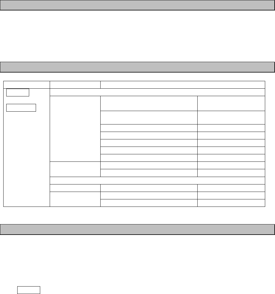
9-2
9.1.5 Environmental condition
Durability and resistance to environmental conditions: protected from the weather (IEC 60945)
(1) Operating temperature : -15°C to +55°C (IEC 60945)
(2) Storage temperature : -25°C to +75°C
(3) Water resistance : IPX2
9.1.6 Supported interface sentences
Indication Sentence format Supported sentence formatters
Input data
Longitude/Latitude
Time of Position
RMC, GGA,GLL
Datum Reference DTM
Speed Over Ground (SOG) RMC, VTG
Course Over Ground (COG) RMC, VTG
Heading HDT
Rate of Turn ROT
IEC61162-1
(NMEA Ver 1.5 -
2.3)
Acknowledge alarm ACK
Request NAVTEX messages NRQ IEC61097-6
Set NAVTEX mask NMK
Output data
IEC61162-1 Set alarm state ALR
New NAVTEX received message NRX
DATA IN
DATA OUT
IEC61097-6
Set NAVTEX mask NMK
9.1.7 Received message log
(1) Stored message : Stores the 200 last received messages (*1). (Each channel)
(2) Saved message : Stores the 50 stored messages (*1). (Each channel)
(*1): message ... 500 character long message
Stored messages are erased 70 hours after their reception.
The source of time for handling message ageing is RMC sentence from an external source
(DATA IN).
When the data from the external source is not inputted, it is counted by the internal timer.

9-3
9.2 NAVTEX ANTENNA (NAW-333 - Option)
9.2.1 Electrical characteristics
(1) Receiving frequency : 518kHz, 490kHz and 4209.5kHz
(2) Bandwidth : 504kHz : ±20kHz
4209.5kHz : ±100kHz
(3) Consumption current : 7Vdc 13mA (Typ.)
(4) Impedance : 50 ohms
9.2.2 Environmental condition
(1) Operating temperature : -25°C to +55°C (IEC 60945)
9.3 POWER SUPPLY UNIT (NBG-320 - Option)
(1) Input voltage : 100-120 / 200-220 Vdc ±10%, 50/60Hz Single phase
: 24Vdc (+30%, -10%) (Back up power supply)
(2) Output voltage : Typ. 12Vdc ±10%
6.5Vdc ±10% (for External Printer)
(3) Maximum current : 1.5 A (24V)
2.0 A (6.5V)
9.4 POWER SUPPLY UNIT (NBG-319 - Option)
(1) Input voltage : 10.8 - 35Vdc
(2) Output voltage : 10.8 - 35Vdc
Typ. 6.5Vdc ±10% (for External Printer)
(3) Maximum current : 1.5 A (12 / 24V)
2.0 A (6.5V)
9-4