Japan Radio NKE2254 Marine Radar User Manual
Japan Radio Co Ltd. Marine Radar Users Manual
Contents
- 1. Users Manual 1
- 2. Users Manual 2
- 3. Users Manual 3
- 4. Users Manual 4
- 5. Users Manual
Users Manual 2
3.4.5 Switch Azimuth Display Mode [AZI MODE]
Select the azimuth for the radar video to be displayed of the display.
Procedures 1 Press the [AZI MODE] key.
The azimuth display modes are switched.
N Up ⇒ C Up ⇒ H Up ⇒ N Up
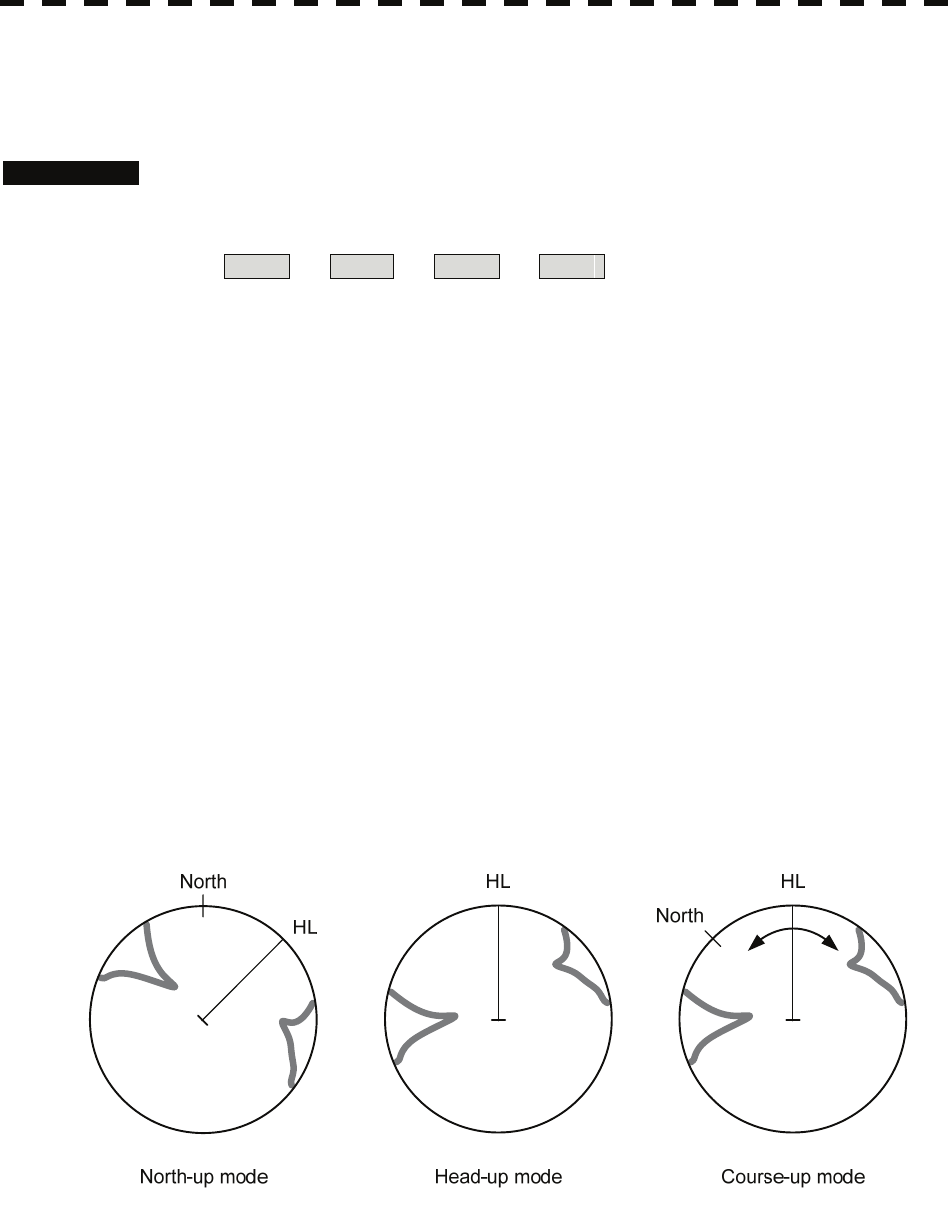
North-up Mode [N Up]
The video is displayed so that the zenith of the PPI (0° on bearing scale) points to the due north.
Fixed targets do not flicker and are easily identified on the chart, and the true bearing of a target can
easily be read out.
Head-up Mode [H Up]
The video is displayed so that the ship’s heading line points to the zenith of the PPI (0° on bearing
scale). Since targets are displayed in their directions relative to the ship’s heading line, the operator
can view the video in the same field of view as in operating the ship at sea. This mode is suitable for
watching over other ships.
Course-up Mode [C Up]
By setting the course-up mode, own ship's course is fixed so that it is located on the zenith of the
display (0° on bearing scale). In the same way as in the North-up mode, fixed targets do not flicker,
and are stabilized even if the ship is yawing. The bearing of the heading line varies by the same shift
of own ship’s course. To change the course, press the [AZI MODE] key several times again to select
the course-up mode so as to set a new course.
3-25
3
3.4 General Radar Operation y
y y
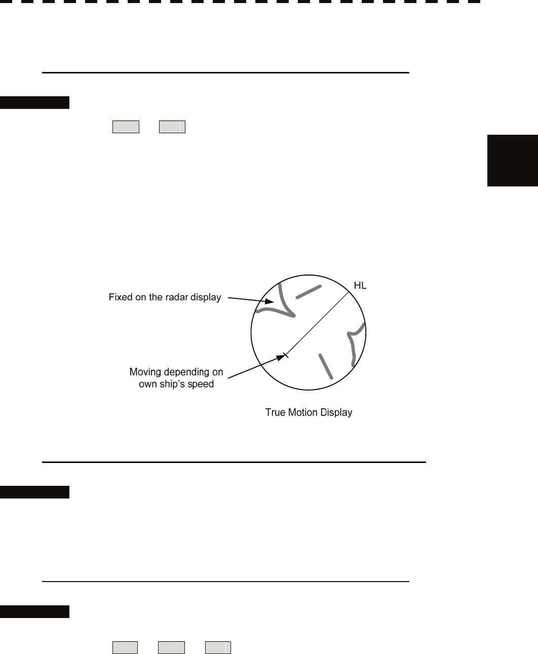
3.4.6 Switch True / Relative Motion Display Mode [TM / RM]
Switching Relative Motion (RM) Mode to True Motion (TM) Mode
Procedures 1 Press the [TM / RM] key.
RM ⇒ TM
The true motion mode will be selected. In the true motion mode, the own ship’s position
of the display moves depending upon its speed and course and the influence of the current.
Land and other fixed targets are fixed of the display and only actually moving targets
move of the display. When the true motion mode is selected, the own ship’s position is set
to about 60% of the display radius in the opposite direction to its course allowing for the
influence of the current. Own ship starts moving depending upon its speed and course and
the influence of the current. Subsequently, when own ship arrives at the position of about
60% of the display radius, it is automatically reset to its initial position at about 66% of
the display radius in the opposite direction to its course allowing for the influence of the
current.
Resetting Own Ship to its Initial Position in True Motion (TM) Mode
Procedures 1 Press the [TM / RM] key for 2 seconds.
Own ship will be reset to its initial position as established when the relative motion mode
is changed to the true motion mode. The ship starts moving from that position.
Switching True Motion (TM) Mode to Relative Motion (RM) Mode
Procedures 1 Press the [TM / RM] key.
TM ⇒ RM ⇒ TM
The relative motion mode will be selected. Own ship returns to the center of the display.
3-26
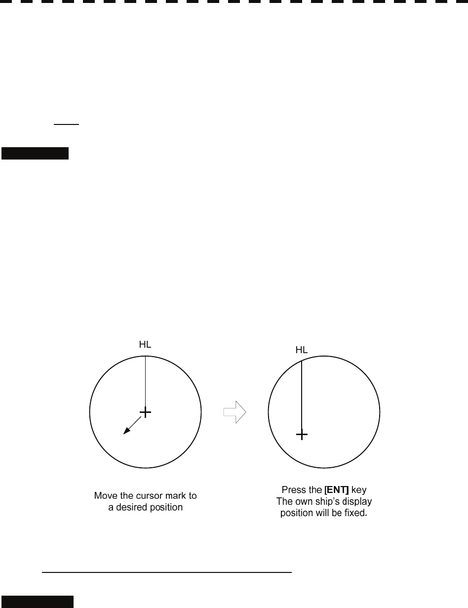
3.4.7 Move Own Ship’s Display Position [OFF CENT]
The own ship’s position can be moved from the display center to any position within 66% of the display
radius. This function is convenient for observing a wide coverage in any direction.
If Off Center functions set to scanner position is outside of the PPI range, when function switching
display with reference to scanner position.
Note: This function is not available on the 96 NM range.
Procedures 1 Press the [OFF CENT] key.
The cursor mark will appear at the own ship’s position of the display.
2 Move the cursor mark (CCRP display position) to a desired position by
using the trackball.
While the cursor mark is moving, the own ship’s display position moves following the
cursor mark.
When it moves to a position outside 66% of the display radius, the center position is
limited to a position within 66% of the display radius.
3 Press the [ENT] key.
The own ship’s display position will be fixed to the cursor mark.
Returning Own Ship’s Position to the Center
Cancellation 1 Press the [OFF CENT] key for 2 seconds.
The own ship position is returned to the center of the display.
3-27

3
3.4 General Radar Operation y
y y
3.4.8 Display Radar Trails [TRAILS]
Other ship's movements and speeds can be monitored from the lengths and directions of their trails,
serving for collision avoidance. The trail length varies according to setting.
Changing the length of the trail
Procedures 1 Press the [TRAILS] key.
Values of the length of the radar trail are switched.
Trails length setting: Short mode
Off ⇒ 15sec ⇒ 30sec ⇒ 1min ⇒ 3min ⇒ 6min ⇒
⇒ 10min ⇒ 15min ⇒ Off
Short: : 15 sec, 30 sec, 1 min, 3 min, 6 min, 10 min, and 15 min
Middle: : 30 sec, 1 min, 3 min, 6 min, 10 min, 15 min, and 30 min
Long: : 1 min, 3 min, 6 min, 10 min, 15 min, 30 min, and 1 hr
Super Long : 30 min, 1 hr, 2 hr, 3 hr, 4 hr, 5 hr, 6 hr, 7 hr, 8 hr, 9 hr, 10 hr, 11 hr,
and 12 hr
Saved trails cannot be erased even when the trail lengths are changed by using [TRAILS]
key. Even after the trails display is turned off, the past trails can be displayed traced back
by setting a desired time.
The radar system is start transmission, trails is start plot.
The system is plotting trails even while the trails display is off.
If the transmit time is short, the indicated trails duration may not have achieved the
specified time. The radar trails remaining time is indicated at the right of the trails length
setting.
Erasing Trails Data
Procedures 1 Press the [TRAILS] key for 5 seconds.
All the saved trails data will be erased. The system starts plotting trails in initial state.
If [TRAILS] key is pressed for 2 seconds, the RADAR Trails Setting menu is opened.
Furthermore, data will be erased if it continues pressing.
3-28
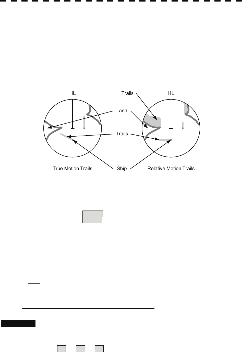
Trails Motion Mode
There are two types of trails, relative motion trails and true motion trails.
Relative motion trails : The system plots the trails of a target at a position relative to the own ship.
The operator can easily judge whether the target is approaching the own
ship.
While the own ship is moving, the system also plots the trails of land and
other fixed targets.
True motion trails : The system plots the absolute motion trails of a target, irrespective of the
own ship’s position.
The operator can easily judge the course and speed of the target.
The system does not plot the trails of land and other fixed targets.
Trails modes provided with this system vary depending on the motion mode.
With true motion (TM) mode : Only the true motion trails mode is available.
With relative motion (RM) mode :
The relative motion trails mode or true motion trails mode is selectable.
RM(R) is indicated while the relative motion trails mode is active.
RM(T) is indicated while the true motion trails mode is active.
While the true motion trails mode is active, this system enables the continuous use of true motion
trails even if any of the following operations is performed:
• Motion display mode change (TM / RM)
• TM reset
• Azimuth display mode change (AZI Mode)
• Center move (Off Center)
• MAP display on / off (Map)
Note: Accurate true bearing signals and speed signals are necessary for using the true motion trails
mode.
Changing Motion Mode of Trails (Trails mode)
Procedures 1 Put the cursor on radar trails display true / relative switching (TT / AIS
information ⑬ on page 2-23), and press the [ENT] key.
The trails motion modes are switched.
T ⇒ R ⇒ T
3-29
3
3.4 General Radar Operation y
y y
3.4.9 Erase Part of Radar Trails (Trails Erase)
A part of the radar trails can be erased.
Procedures 1 Press the [TRAILS] key for 2 seconds.
The RADAR Trails Setting menu will appear.
2 Open the Trails Erase menu by performing the following menu
operation.
7. Trails Erase
3 Press the [3] key.
The Erase Size switches.
2x2 : 2x2 pixels
4x4 : 4x4 pixels
8x8 : 8x8 pixels
16x16 : 16x16 pixels
32x32 : 32x32 pixels
4 Press the [1] key.
The Trails Erase Mode is set to On .
A square cursor □ will appear at the location of own ship.
5 Put the cursor on the position where you want to start erasing, and
press the [2] key.
The Trails Erase Start function is selected and trails start to be erased.
Moving the cursor will erase that portion of the trails.
6 To finish erasing the trails, press the [2] key.
The trails erase operation is terminated.
7 Press the [1] key.
The Trails Erase Mode is set to Off .
3-30
3.4.10 Operate Radar Trails File (File Operations)
[I] Loading radar trails (Load RADAR Trails)
Procedures 1 Insert a flash memory card into the card slot.
Flash memory card (option) is necessary.
For the insertion and removal of the card, see HOW TO INSERT AND REMOVE A
CARD in the appendix.
2 Press the [TRAILS] key for 2 seconds.
The RADAR Trails Setting menu will appear.
3 Open the File Operations menu by performing the following menu
operation.
8. File Operations
4 Press the [1] key to select a card slot.
Slot1 and Slot2 of the Select Card Slot items are switched.
5 Press the [2] key.
The list of radar trails saved in the card will be displayed.
6 Press numeric keys corresponding to the desired file.
Confirmation Window will appear.
7 Press the [1] key.
The selected radar trails data is loaded and displayed of the display.
[II] Saving radar trails (Save RADAR Trails)
Procedures 1 Insert a flash memory card into the card slot.
Flash memory card (option) is necessary.
For the insertion and removal of the card, see HOW TO INSERT AND REMOVE A
CARD in the appendix.
2 Press the [TRAILS] key for 2 seconds.
The RADAR Trails Setting menu will appear.
3 Open the File Operations menu by performing the following menu
operation.
8. File Operations
4 Press the [1] key to select a card slot.
Slot1 and Slot2 of the Select Card Slot items are switched.
3-31

3
3.4 General Radar Operation y
y y
5 Press the [3] key.
The Input File Name screen will appear.
6 Enter the file name to be saved.
Up to 15 characters can be entered.
For the input method on the character input screen, see Section 3.3.4.
After characters have been entered, Confirmation Window will appear.
7 Press the [1] key.
Radar trails data currently being displayed is saved.
[III] Erasing save radar trails (Erase RADAR Trails)
Procedures 1 Insert a flash memory card into the card slot.
Flash memory card (option) is necessary.
For the insertion and removal of the card, see HOW TO INSERT AND REMOVE A
CARD in the appendix.
2 Press the [TRAILS] key for 2 seconds.
The RADAR Trails Setting menu will appear.
3 Open the File Operations menu by performing the following menu
operation.
8. File Operations
4 Press the [1] key to select a card slot.
Slot1 and Slot2 of the Select Card Slot items are switched.
5 Press the [4] key.
The File Erase menu will appear.
The list of radar trails saved in the card will be displayed.
6 Press numeric keys corresponding to the desired file number.
Confirmation Window will appear.
7 Press the [1] key.
The selected radar trails data is erased and the name of the radar trails data is deleted from
the list.
3-32
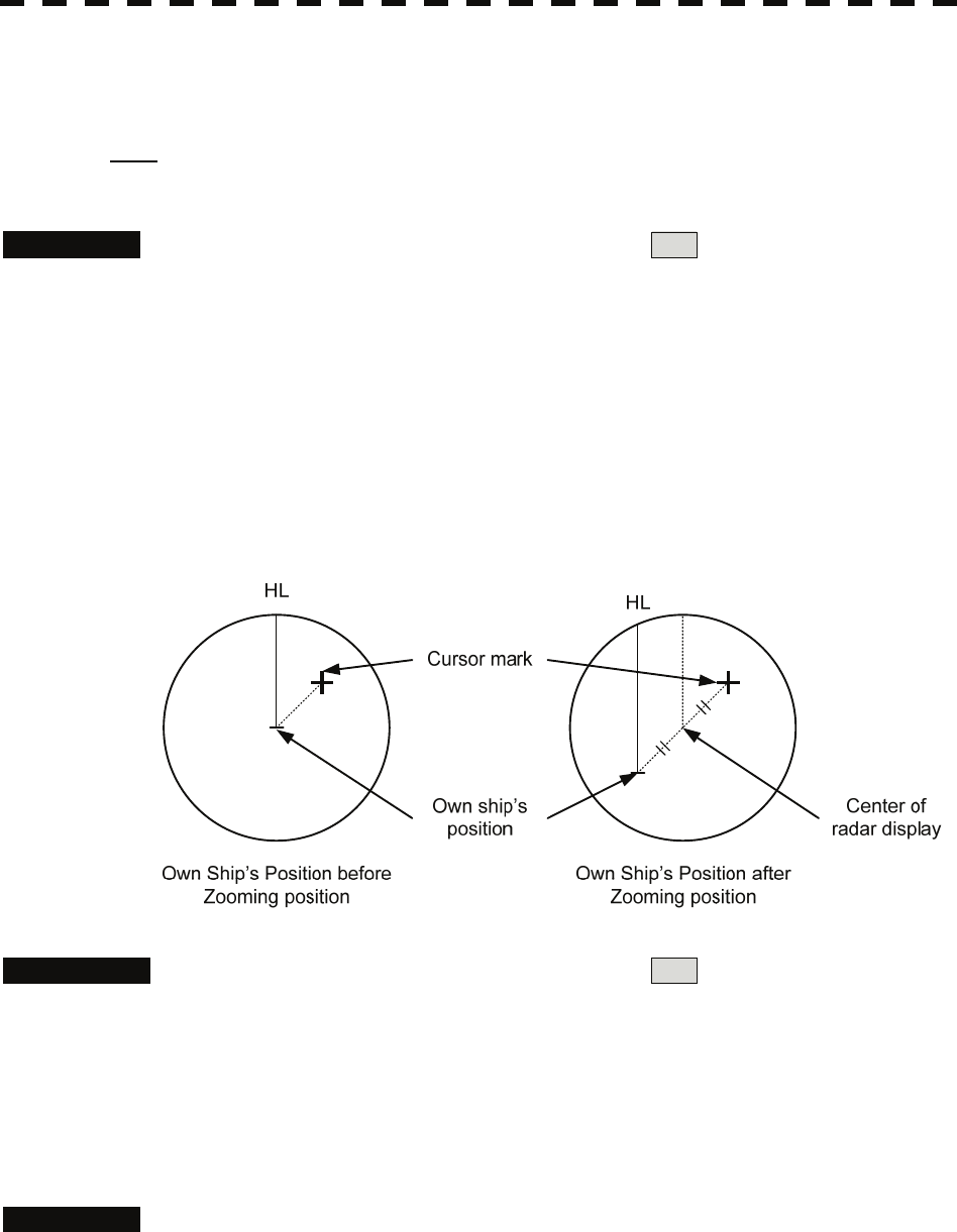
3.4.11 Zoom (x2)
This function doubles the size of radar video near a specified position.
Note: If the range is 0.125 NM or motion mode is true motion mode (TM), this function is not
available.
Procedures 1 Put the cursor on double zoom switching x2 (lower left of the display
① on page 2-18), and press the [ENT] key.
The zoom mode is selected.
2 Put the cursor on the position to be zoomed, and then press the [ENT]
key.
The zoom is set.
Using the cross cursor mark as reference, the zoom function doubles the size of a radar video
with the midpoint between the cursor mark and own ship’s position being set to the center of
radar display.
Cancellation 1 Put the cursor on double zoom switching x2 (lower left of the display
① on page 2-18), and press the [ENT] key.
The zoom mode is cancelled.
3.4.12 Hide / Display Range Rings (RR / HL)
Procedures 1 Press the [RR / HL] key for 2 seconds or more.
The ship's heading line (HL) is hidden while the [RR / HL] key is held down.
The ship's heading line that indicates the course of own ship is always shown of the
display. The heading line is hidden while the [RR / HL] key is held down, so the targets
on the heading line can be easily observed.
3-33
3
3.4 General Radar Operation y
y y
3.4.13 Hide Graphics Information on Radar Display (Data Off)
Various graphics information such as target tracking (TT) / AIS symbols, NAV lines, and MAP
information is shown of the display of this radar system, and may make it difficult to view the radar
video. In that case, use this function to temporarily hide unnecessary graphics information.
Procedures 1 Put the cursor on graphic display Off Data Off (lower right on the
display ⑤ on page 2-21), and press the [ENT] key.
While the key is pressed, graphics data other than VRM, EBL, HL, cursor mark, and
range rings of the display is temporarily hidden.
3.4.14 Switch Day / Night Mode [DAY / NIGHT]
Several combinations of the display color and brilliance according to the ambient lighting conditions are
provided. The display color setting is easily changed.
Procedures 1 Press the [DAY / NIGHT] key.
The Day / Night modes are switched.
Day1 ⇒ Day2 ⇒ Day3 ⇒ Dusk ⇒ Night ⇒ Dusk ⇒
Day3 ⇒ Day2 ⇒ Day1
The current mode is displayed in the Day / Night mode switching (brilliance / Alarm ⑤
on page 2-28).
For how to set the display color and brilliance for each mode, see Section 3.8.6.
3.4.15 Adjust Operation Panel Brilliance [PANEL]
Adjust brilliance of the operation panel according to the ambient lighting conditions.
Procedures 1 Press the [PANEL] key.
In consideration of the ambient brightness, adjust panel brilliance that is high enough to
read the characters on the operation panel but does not glare.
The [PANEL] key lamp lights up irrespective of panel brilliance adjustment.
3-34
3.4.16 Set True Bearing (GYRO Setting)
When the GYRO I/F unit is used to enter a gyro signal, there is a rare case in which a true bearing value
indicated by the master gyro does not match the true bearing value indicated by this radar system.
In that case, adjust the true bearing value of this system so that it matches the value indicated by the
master gyro.
Procedures 1 Press the [AZI MODE] key for 2 seconds.
The numeric value input menu for the GYRO Setting menu will appear.
2 Enter the value indicated by the master gyro.
For how to input numeric data on the numeric value input menu, see Section 3.3.4.
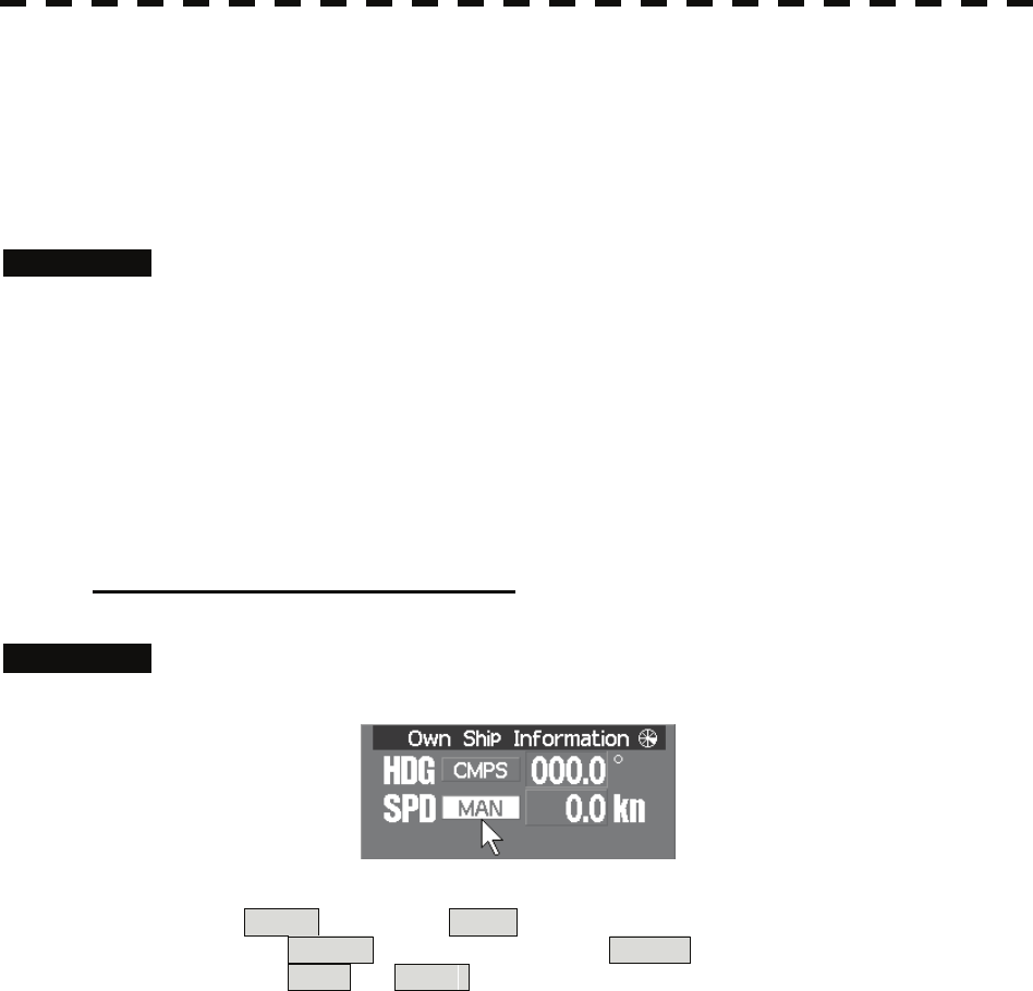
3.4.17 Set Own Ship Speed
Switch the own ship speed device
Procedures 1 Put the cursor on speed sensor switching (own ship information ② on
page 2-22), and press the [ENT] key.
The speed sensor is switched whenever the button is clicked.
MAN (Manual) ⇒ LOG (Single-axis water log)
⇒ 2AXW (Dual-axis water log) ⇒ 2AXG (Dual-axis ground log)
⇒ GPS ⇒ MAN
* If the single axis water log display can present the speed of the ship in other than the
forward direction, the direction of movement should be indicated unambiguously.
Therefore single axis water logs cannot detect the effect of leeway.
If ships in shallow water, when the accuracy of the dual-axis log may be decreased.
If ships in deep sea area, when the accuracy of the dual-axis log error may be
occurred.
The accuracy of GPS's COG is ±3° when own ships speed no fewer than 1kn, no more
than 17kn. The accuracy of GPS's COG is ±1° when own ships speed over 17kn.
3-35
3
3.4 General Radar Operation y
y y
Input the own ship speed (Manual Speed)
If the ship-speed system, such as LOG, etc., connected to this radar system malfunctions, it is possible to
manually enter own ship speed by the method described below to use the target tracking (TT) and true
motion display functions.
Procedures 1 Put the cursor on speed sensor switching (own ship information ② on
page 2-22), and press the [ENT] key to select manual mode MAN .
2 Put the cursor on manual own ship's speed setting (own ship
information ④ on page 2-22), and press the [ENT] key.
The numeric value input screen for the Manual Speed menu will appear.
3 Enter the value of own ship speed.
For how to input numeric data on the numeric value input screen, see Section 3.3.4.
3.4.18 Magnet Compass Correction (MAG Compass Setting)
Set the correction value, when the radar receive HDM sentence from magnet compass or the variation of
HDG is NULL.
Procedures 1. Press the [RADAR MENU] key twice.
2 Open the MAG Compass Setting menu by performing the following
menu operation.
4. NAV equipment Setting
→ 2. MAG Compass Setting
2. Press the [1] key.
The Heading Correction function can be turned on / off.
Off : Heading correction is not conducted.
On : Heading correction is conducted.
3. Press the [2] key.
The correction set numeric value input menu will appear.
4. Input the correction value.
Press the + or - button to select south and north for latitude or the east and west
for longitude.
For how to input numeric data on the numeric value input screen, see Section 3.3.4.
3-36
3.4.19 Set Drift Correction (Set / Drift Setting)
The direction and speed of the drift are set.
This function can be used only when MAN or LOG is selected for ship-speed data.
Procedures 1 Press the [RADAR MENU] key twice.
2 Open the Set / Drift Setting menu by performing the following menu
operation.
4. NAV Equipment Setting
→ 3. Set/Drift Setting
3 Press the [1] key.
The Correction function can be turned on / off.
Off : Drift correction is not conducted.
On : Drift correction is conducted.
4 Press the [2] key.
The direction set numeric value input menu will appear.
5 Enter the value of the drift direction (true bearing).
For how to input numeric data on the numeric value input menu, see Section 3.3.4.
6 Press the [3] key.
The drift speed numeric value input menu will appear.
7 Enter the value of the drift speed.
For how to input numeric data on the numeric value input menu, see Section 3.3.4.
3-37
3
3.4 General Radar Operation y
y y
3.4.20 GPS Receiver Setting (GPS Process Setting)
Set to a JRC’s GPS receiver.
This setting is enabled when a JRC’s GPS is connected to the GPS connector of processor unit.
[I] Own Ship’s position setting (Position)
Procedures 1. Press the [RADAR MENU] key twice, and then perform the following
menu open procedure to open the Position menu.
4. NAV equipment Setting
→ 4. GPS Setting
→ 1. GPS Process Setting
→ 1. Position
2. Enter the own ship’s position in the numeric value input menu.
For the input method on the latitude / longitude input screen, see Section 3.3.4.
3. Press the [9] key to send the setting value to GPS receiver.
[Ⅱ] Satellite exclusion setting (Exclusion)
Procedures 1. Press the [RADAR MENU] key twice, and then perform the following
menu open procedure to open the Exclusion menu.
4. NAV Equipment Setting
→ 4. GPS Setting
→ 1. GPS Process Setting
→ 2. Exclusion
2. Enter the satellite exclusion number in the numeric value input menu.
For the input method on the numeric value input screen, see Section 3.3.4.
3. Press the [9] key to send the setting value to GPS receiver.
3-38

[Ⅲ] Geodetic system setting (Geodetic)
Procedures 1. Press the [RADAR MENU] key twice, and then perform the following
menu open procedure to open the Geodetic menu.
4. NAV Equipment Setting
→ 4. GPS Setting
→ 1. GPS Process Setting
→ 3. Geodetic
2. Enter the geodetic system number in the numeric value input menu
refer to next page.
3. Press the [9] key to send the setting value to GPS receiver.
[Ⅳ] Antenna height setting (Antenna height)
Procedures 1. Press the [RADAR MENU] key twice, and then perform the following
menu open procedure to open the Antenna Height menu.
4. NAV Equipment Setting
→ 4. GPS Setting
→ 1. GPS Process Setting
→ 4. Antenna height
2. Enter the GPS antenna height in the numeric value input menu.
3. Press the [9] key to send the setting value to GPS receiver.
[Ⅴ] Fix mode setting (Fix mode)
Procedures 1. Press the [RADAR MENU] key twice, and then perform the following
menu open procedure to open the Fix Mode menu.
4. NAV Equipment Setting
→ 4. GPS Setting
→ 1. GPS Process Setting
→ 5. Fix Mode
2. Select the fix mode.
2D : height is measured in two dimensions
3D : height is measured in three dimensions
AUTO :select the proper dimension to measure a height automatically
3. Press the [9] key to send the setting value to GPS receiver.
3-39
3
3.4 General Radar Operation y
y y
Geodetic System List
番号 名称
0 WGS-84
1 WGS-72
2 Japan
3 North American 1927(U.S)
4 North American 1927(Canada & Alaska)
5 European 1950 (Europe)
6 Australian geodetic 1966 (Australia)
7 Ordnance Survey of Great Britain (England)
8 NAD-83
9 - (No Use)
10 - (No Use)
11 ADINDAN (Ethiopia & Sudan)
12 ARC 1950 (Botswana)
13 AUSTRALIAN GEODETIC 1984 (Australia)
14 BERMUDA 1957 (Bermuda islands)
15 BOGOTA OBSERVATORY (Colombia)
16 CAMPO INCHAUSPE (Argentine)
17 CHATHAM 1971 (Chatham Islands)
18 CHUA ASTRO (Paraguay)
19 CORREGO ALEGRE (Brazil)
20 DJAKARTA (VATAVIA) (Sumatra)
21 EUROPEAN 1979 (Europe)
22 GEODETIC DATUM 1949 (New Zealand)
23 GUAM 1963 (Guam)
24 HAYFORD 1910 (Finland)
25 HJORSEY 1955 (Iceland)
26 INDIAN (India & Nepal)
27 IRELAND1965 (Ireland)
28 KERTAU 1948 (West Malaysia)
29 L.C.5 ASTRO (Cayman Brac Island)
30 LIBERIA 1964 (Liberia)
31 LUZON (Philippines)
32 MERCHICH (Morocco)
33 MINNA (Nigeria)
34 NAHRWAN (Oman)
35 NAPARIMA, BWI (Trinidad & Tobago)
36 OLD EGYPTIAN (Egypt)
37 OLD HAWAIIAN (Hawaii)
38 PICO DE LAS NIEVES (Canary Islands)
39 PROVISIONAL SOUTH AMERICAN 1956 (South America)
40 PROVISIONAL SOUTH CHILEAN 1963 (South Chile)
41 PUERTO RICO (Puerto Rico & Virgin Islands)
42 QORNOQ (South Greenland)
43 RT90 (Sweden)
44 SANTA BRAZ (San Miguel island & Santa Maria islands)
45 SOUTH AMERICAN 1969 (South America)
46 SOUTHWEST BASE (Faial & Sao Jorge & Pico & Graciosa & Terceira island)
47 TIMBALAI 1948 (Brunei & East Malaysia)
48 - (No Use)
49 - (No Use)
3-40
[Ⅵ] HDOP level setting (DOP Level)
Procedures 1. Press the [RADAR MENU] key twice, and then perform the following
menu open procedure to open the DOP Level menu.
4. NAV Equipment Setting
→ 4. GPS Setting
→ 1. GPS Process Setting
→ 6. DOP Level
2. Enter the HDOP level in the numeric value input menu.
When the HDOP level is decrease, the accuracy is increased. But it is hard to measure the
position.
3. Press the [9] key to send the setting value to GPS receiver.
[Ⅶ] Position average time setting (Position Average)
Procedures 1. Press the [RADAR MENU] key twice, and then perform the following
menu open procedure to open the Position Average menu.
4. NAV Equipment Setting
→ 4. GPS Setting
→ 1. GPS Process Setting
→ 7. Position Average
2. Set the position average time.
The following are provided according to the ROM version of GPS receiver.
ROM Version R26.00: Select the average time
LONG(40sec)
STANDARD(10sec)
NONE(2sec)
Other ROM Version: Enter the average time
When the average time is short, the renewal speed is increased. But the stability become
worse.
3. Press the [9] key to send the setting value to GPS receiver.
3-41
3
3.4 General Radar Operation y
y y
[Ⅷ] Master reset
Procedures 1. Press the [RADAR MENU] key twice, and then perform the following
menu procedure to set the Master Reset On.
4. NAV Equipment Setting
→ 4. GPS Setting
→ 1. GPS Process Setting
→ 8. Master Reset
2. Press the [9] key to send the setting value while the master reset is on.
3.4.21 DGPS Receiver Setting (DGPS Setting)
Set to a JRC’s DGPS receiver.
This setting is enabled when a JRC’s DGPS is connected to the GPS connector of processor unit.
[I] Beacon frequency mode setting (Mode)
Procedures 1. Press the [RADAR MENU] key twice, and then perform the following
menu open procedure to open the DGPS Setting menu.
4. NAV equipment Setting
→ 4. GPS Setting
→ 2. DGPS Setting
2. Press the [1] key to select the beacon frequency mode.
AUTO : The beacon frequency mod is selected automatically
Manual : The beacon frequency mod is selected manually
3. Press the [5] key to send the setting value to DGPS receiver.
[Ⅱ] Beacon frequency setting(Frequency)
This setting is enabled when beacon frequency mode is set to manual.
Procedures 1. Press the [RADAR MENU] key twice, and then perform the following
menu open procedure to open the Frequency menu.
4. NAV equipment Setting
→ 4. GPS Setting
→ 2. DGPS Setting
→ 2. Frequency
2. Enter the beacon frequency.
3. Press the [5] key to send the setting value to DGPS receiver.
3-42
[Ⅲ] baud rate setting(Baud Rate(BPS))
This setting is enabled when beacon frequency mode is set to manual.
Procedures 1. Press the [RADAR MENU] key twice, and then perform the following
menu open procedure to open the Baud Rate menu.
4. NAV equipment Setting
→ 4. GPS Setting
→ 2. DGPS Setting
→ 3. Baud Rate(BPS)
2. Select the baud rate.
Following baud rate is selectable
50bps/100bps/200bps
3. Press the [5] key to send the setting value to DGPS receiver.
[Ⅳ] DGPS Mode setting(DGPS Mode)
When DGPS mode set to on, DGPS use the information from beacon to get reliable
position.
When DGPS mode set to off, the accuracy of position is same as GPS.
Procedures 1. Press the [RADAR MENU] key twice, and then perform the following
menu open procedure to open the DGPS Mode menu.
4. NAV equipment Setting
→ 4. GPS Setting
→ 2. DGPS Setting
2. Press [4] key to select the DGPS Mode.
On : DGPS use the information from beacon
Off : DGPS don’t use the information from beacon
3. Press the [5] key to send the setting value to DGPS receiver.
3.4.22 SBAS Receiver Setting (SBAS Setting)
Set to a JRC’s SBAS receiver.
SBAS receiver use the information from satellite same as that of beacon which DGPS use. So the
accuracy of position is higher than GPS.
This setting is enabled when a JRC’s DGPS is connected to the GPS connector of processor unit.
[I] SBAS mode setting (Mode)
Select the satellite or the beacon whose differential information is used.
3-43
3
3.4 General Radar Operation y
y y
Procedures 1. Press the [RADAR MENU] key twice, and then perform the following
menu open procedure to open the Mode menu.
4. NAV equipment Setting
→ 4. GPS Setting
→ 3. SBAS Setting
→ 1. Mode
2. Select the satellite or the beacon whose differential information is used.
Beacon : SBAS receiver use the information from beacon
SBAS : SBAS receiver use the information from SBAS satellite
AUTO : SBAS receiver selects automatically
3. Press the [6] key to send the setting value to SBAS receiver.
[Ⅱ] Ranging satellite setting (Ranging)
Set the SBAS satellite to be used or not to be used.
Procedures 1. Press the [RADAR MENU] key twice, and then perform the following
menu open procedure to open the SBAS Setting menu.
4. NAV equipment Setting
→ 4. GPS Setting
→ 3. SBAS Setting
2. Press [2] key to select the SBAS satellite to be used or not to be used.
On : SBAS satellite is used
Off : SBAS satellite is not used
3. Press the [6] key to send the setting value to SBAS receiver.
[Ⅲ] Prohibitive satellite setting (NG SBAS)
Set the information from prohibitive SBAS satellite to be used or not to be used.
Procedures 1. Press the [RADAR MENU] key twice, and then perform the following
menu open procedure to open the SBAS Setting menu.
4. NAV equipment Setting
→ 4. GPS Setting
→ 3. SBAS Setting
2. Press [3] key to select the information from prohibitive SBAS satellite to
be used or not to be used.
On : The information from prohibitive SBAS satellite is used
Off : The information from prohibitive SBAS satellite is not used
3. Press the [6] key to send the setting value to SBAS receiver.
3-44
[Ⅳ] Satellite number select mode setting (SBAS Select Mode)
Set the satellite number select mode.
Procedures 1. Press the [RADAR MENU] key twice, and then perform the following
menu open procedure to open the SBAS Setting menu.
4. NAV equipment Setting
→ 4. GPS Setting
→ 3. SBAS Setting
2. Press [4] key to select the satellite number select mode.
Manual : SBAS satellite number is set manually
AUTO : SBAS satellite number is set automatically
3. Press the [6] key to send the setting value to SBAS receiver.
[Ⅴ] Satellite number setting (SBAS No.)
Set the satellite number.
This setting is enabled when satellite number select mode is set to manual.
Procedures 1. Press the [RADAR MENU] key twice, and then perform the following
menu open procedure to open the SBAS No. menu.
4. NAV equipment Setting
→ 4. GPS Setting
→ 3. SBAS Setting
→ 5. SBAS No.
2. Enter the satellite number.
Enter the number from 120 to 138.
3. Press the [6] key to send the setting value to SBAS receiver.
3-45
3
3.4 General Radar Operation y
y y
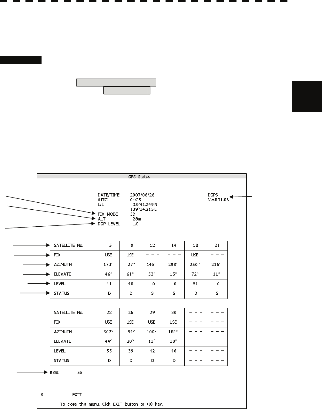
3.4.23 Displaying GPS Reception Status (GPS Status)
The reception status of GPS(GPS/DGPS/WAAS) which is connected to radar processor unit is displayed.
This setting is enabled when a JRC’S GPS/DGPS/WAAS is connected to the GPS connector of processor
unit.
Procedures 1. Press the [RADAR MENU] key twice, and then perform the following
menu open procedure to open the GPS Status window.
4. NAV equipment Setting
→ 4. GPS Status
2. After check of the GPS status, press [0] key to close the GPS status
window.
This window cannot be opened in the transmission state.
Received Signal
Strength Indicator
Status of satellite
S: Search
T: Tracking
D: Data detection complete
Elevate of satellite
Received si
g
nal level
Azimuth of satellite
Use
d
satellite
Satellite numbe
r
Accuracy
(Small number is high accuracy)
Software version
Fix mode
Antenna height
(If 2D is used, this
is initial value)
3-46
3.4.24 Set Radar Alarm (RADAR Alarm)
The radar alarm can be issued when targets have entered the radar alarm range.
Turning on / off the radar alarm (Sector RADAR Alarm)
Procedures 1 Press the [AZ] key for 2 seconds.
The AZ Menu will appear.
2 Open the Sector RADAR Alarm menu by performing the following menu
operation.
4. RADAR Alarm
→ 1. Sector RADAR Alarm
3 Press the [1] key or [2] key.
Sector Alarm1 or Sector Alarm2 is turned on / off.
On : The radar alarm is turned on.
Off : The radar alarm is turned off.
Change the Radar Alarm Setting (RADAR Alarm Mode)
Procedures 1 Press the [AZ] key for 2 seconds.
The AZ Menu will appear.
2 Open the Sector RADAR Alarm menu by performing the following menu
operation.
4. RADAR Alarm
3 Press the [5] key.
Sector Alarm1 or Sector Alarm2 is turned on / off.
In : When a target has entered the zone, RADAR Alarm (In) is issued.
Out : When a target has departed the zone, RADAR Alarm (Out) is issued.
4 Press the [6] key.
Selected items for Sensitivity Level will be displayed.
5 Press numeric keys corresponding to the Sensitivity Level.
The threshold video level increases in order of
Level1 → Level2 → Level3 → Level4 .
3-47
3
3.4 General Radar Operation y
y y
Creating the radar alarm zone (Make Sector Alarm)
Procedures 1 Press the [AZ] key for 2 seconds.
The AZ Menu will appear.
2 Open the Make Sector Alarm menu by performing the following menu
operation.
4. RADAR Alarm
→ 3. Make Sector Alarm
3 Press the [1] key or [2] key.
The range setting for Sector Alarm1 or Sector Alarm2 starts.
4 Turn the [EBL] dial and the [VRM] dial to set the start bearing and the
start range, and then press the [ENT] key.
5 Turn the [EBL] dial and the [VRM] dial to set the end bearing and the end
range, and then press the [ENT] key.
The radar alarm zone is determined.
Setting the [AZ] key allocation (Set AZ Key)
Only by pressing the [AZ] key, the normally-used radar alarm can be easily turned on /
off.
Procedures 1 Press the [AZ] key for 2 seconds.
The AZ Menu will appear.
2 Open the Sector RADAR Alarm menu by the following menu operation.
5. Set AZ Key
→ 2. Sector RADAR Alarm
3 Set the [AZ] key allocation.
On : Pressing the [AZ] key will turn on or off the radar alarm.
Off : Even if the [AZ] key is pressed, the radar alarm zone is not turned on.
Note: When the automatic acquisition / activation zone key allocation is set, pressing the [AZ] key
will simultaneously turn on or off the radar alarm in the automatic acquisition / activation zone.
3-48
3.5 USE OWN SHIP'S TRACK DATA
The own ship's track function saves and displays own ship's track.
If navigation equipment is connected, this radar system records latitude / longitude data sent from the
navigation equipment and displays own ship's track.
Note: Even when own ship's track interval switching (lower right of the display ③ on page 2-21) is
set to Off , own ship's track can be displayed. However, in this case, if rewrite operation such
as changing of the display range is performed for the radar display, own ship's track display is
erased and the track will not be plotted again.
If the DISP Own Track is turned off when the own ship track is in save, own ship's track is not
shown of the display, but own ship's track data is still saved.
When a plotter unit (optional) is connected, own ship's track can be displayed and saved in seven
different colors. The color display can be turned on or off by color.
3.5.1 Display Own Ship’s Track (Display Own Track)
Procedures 1 Open the Own Track Menu by the following menu operation.
O.TRK
2 Press the [1] key.
The DISP Own Track function item is turned on or off.
On : Own ship's track is displayed.
Off : Own ship's track is not displayed.
3 Press the [MAP] key.
The map display function is turned on or off.
Selecting On will display own ship's track.
3-49
3
3.5 Use Own ship's track data y
y y
3.5.2 Save Own Ship's Track Data (Own Track Memory)
To save own ship's track data, save at a specified time interval and at a specified range
interval can be selected.
The data save interval can be selected from 10 preset time intervals and 8 preset range
intervals.
Save intervals that can be selected
Time : 3 sec, 5 sec, 10 sec, 30 sec, 1 min,
3 min, 5 min, 10 min, 30 min, and 60 min
Range : 0.1 NM, 0.2 NM, 0.3 NM, 0.5 NM,
1 NM, 3 NM, 5 NM, and 10 NM
Procedures 1 Put the cursor on own ship's track interval unit switching (lower right of
the display ④ on page 2-21), and press the [ENT] key.
Units of own ship's track interval are switched.
2 Put the cursor on own ship's track interval switching (lower right of the
display ③ on page 2-21), and press the [ENT] key.
Own ship's track intervals are switched.
Setting the button to Off cancels the saving of data.
3.5.3 Cancel Saving of Own Ship’s Track Data (Own Track Memory)
This function cancels the saving of own ship’s track data.
Procedures 1 Put the cursor on own ship's track interval switching (lower right of the
display ③ on page 2-21), and press the [ENT] key.
Own ship's track intervals are switched.
Selecting Off will cancel the saving of data.
3.5.4 Clear Own Ship’s Track Data (Clear Own Track)
This function clears own ship’s track data from memory.
Procedures 1 Open the Own Track Menu by the following menu operation.
O.TRK
2 Press the [2] key.
Clear Own Track Confirmation Window will appear.
3 Press the [1] key.
The own ship’s track data will be cleared.
3-50
3.5.5 Operate Own ship's Track Files (File Operations)
[I] Loading own ship's track data (Load Own Track)
Procedures 1 Insert a flash memory card into the card slot.
Flash memory card (option) is necessary.
For the insertion and removal of the card, see HOW TO INSERT AND REMOVE A
CARD in the appendix.
2 Open the File Operations menu by the following menu operation.
O.TRK
→ 5. File Operations
3 Press the [1] key to select a card slot.
Slot1 and Slot2 of the Select Card Slot items are switched.
4 Press the [2] key to select Add or Overwrite.
Add and Overwrite in the Load Mode items are switched.
When Add is selected, new data is added to the saved data. When Overwrite is
selected, the saved data is overwritten.
5 Press the [3] key.
The list of own ship's tracks data saved in the system will be displayed.
6 Press numeric keys corresponding to the file to be loaded.
Confirmation Window will appear.
7 Press the [1] key.
The selected own ship's track data is loaded and displayed of the display.
3-51
3
3.5 Use Own ship's track data y
y y
[II] Saving own ship's track data (Save Own Track)
Procedures 1 Insert a flash memory card into the card slot.
Flash memory card (option) is necessary.
For the insertion and removal of the card, see HOW TO INSERT AND REMOVE A
CARD in the appendix.
2 Open the File Operations menu by performing the following menu
operation.
O.TRK
→ 5. File Operations
3 Press the [1] key to select a card slot.
Slot1 and Slot2 of the Select Card Slot items are switched.
4 Press the [4] key.
The character input screen for Input File Name will appear.
5 Enter the file name to be saved.
Up to 10 characters can be entered.
For the input method on the character input screen, see Chapter 3.3.4.
After entry has been finished, Confirmation Window will appear.
6 Press the [1] key.
Own ship's track data currently being displayed is saved.
[III] Erasing own ship's track data (Erase Own Track)
Procedures 1 Insert a flash memory card into the card slot.
Flash memory card (option) is necessary.
For the insertion and removal of the card, see HOW TO INSERT AND REMOVE A
CARD in the appendix.
2 Open the File Operations menu by performing the following menu
operation.
O.TRK
→ 5. File Operations
3 Press the [1] key to select a card slot.
Slot1 and Slot2 of the Select Card Slot items are switched.
4 Press the [5] key.
The Erase screen will appear.
The list of own ship's track data saved in the card will be displayed.
3-52
5 Press numeric keys corresponding to the file to be deleted.
Confirmation Window will appear.
6 Press the [1] key.
The selected own ship's track data is deleted and the file name is deleted from the list.
[IV] Displaying saved own ship's track data (Card Own Track Display)
Procedures 1 Insert a flash memory card into the card slot.
Flash memory card (option) is necessary.
For the insertion and removal of the card, see HOW TO INSERT AND REMOVE A
CARD in the appendix.
2 Open the File Operations menu by performing the following menu
operation.
O.TRK
→ 5. File Operations
3 Press the [1] key to select a card slot.
Slot1 and Slot2 of the Select Card Slot items are switched.
4 Press the [6] key.
The Card Own Track Display menu will appear.
The list of own ship's track data saved in the card will be displayed.
5 Press numeric keys corresponding to the number for the file to be
displayed.
Confirmation Window will appear.
6 Press the [1] key.
The saved own ship's track data will be displayed.
3-53
3
3.6 Display User Map y
y y
3.6 DISPLAY USER MAP
Up to 2,000 items (20,000 items when a plotter unit option is connected) of NAV lines, coastlines, depth
contours, and NAV marks can be created, displayed, loaded, and saved. (This function is available only
when navigation equipment is connected to this radar system.)
If the number of items exceeds 2,000, the oldest saved items are sequentially deleted.
Up to 20 items of temporarily used marks can be created and displayed.
Marks that can be used : 29 types
Lines that can be used : 3 types (solid, broken, and dashed-dotted line)
Color of mark and line that can be used : 7 colors
If radar video is poor visibility caused by user map function, press the [DATA OFF] key to map displays
temporarily off.
3.6.1 Create User Map (Mark / Line)
In this system, when the radar is in the transmission state, the user map is displayed all the time. However,
valid latitude / longitude data and true bearing data must be entered into the system.
The user map can be created and edited by performing the following operation.
Plotting a mark
Procedures 1 Press the [MARK] key to select the mark mode.
The mark font to be used is displayed in the mark font switching (upper right of the
display ② on page 2-19).
2 Put the cursor on mark font switching (upper right of the display
② on page 2-19), and press the [ENT] key.
The mark fonts are switched.
3 Put the cursor mark on mark color switching C (upper right of the
display ③ on page 2-19), and press the [ENT] key.
The mark colors are switched.
4 Put the cursor on a location of the display at which you want to plot the
mark, and press the [ENT] key.
The specified mark is displayed in the specified shape and color.
To create another mark, repeat the above procedures.
3-54
Plotting a line
Procedures 1 Press the [MARK] key to select the line mode.
The line pattern to be used is displayed in the line pattern switching (upper right of the
display ② on page 2-19).
2 Put the cursor on line pattern switching ------- (upper right of the
display ② on page 2-19), and press the [ENT] key.
Line patterns are switched.
3 Put the cursor on line color switch C (upper right of the display ③
on page 2-19), and press the [ENT] key.
Line colors are switched.
4 Put the cursor on a location of the display at which you want to start
plotting a line, and press the [ENT] key.
The start point of the specified line will be displayed.
5 Move the cursor to a location of the display at which you want to finish
plotting the line, and press the [ENT] key.
A line is plotted between the previous point and the end point.
Repeat this procedure so that sequential lines can be plotted.
6 When you want to finish plotting the line, press the [ENT] key at the
previous point.
Line plotting will be terminated.
To plot another line, repeat procedures 4 to 6.
3-55
3
3.6 Display User Map y
y y
Plotting a mark / line make with latitude and longitude
Procedures 1 Open the Edit User Map menu by performing the following menu
operation.
Plot
→ 2. Mark Operations
→ 2. Edit User Map
2 Press the [2] key.
The Make with L/L menu will appear.
3 Press the [9] key to select the New Mark Input or New Line Input.
The Mark Input menu and the Line Input menu are switched.
4 Press the [1] key to select the type of mark font or line pattern to be
created.
The desired mark font or line pattern is selected.
To add a line, select midpoint --O-- .
5 Press the [2] key to select the color of mark or line to be created.
The desired mark or line color is selected.
6 Press the [3] key to input the latitude / longitude.
For the input method on the latitude / longitude input screen, see Section 3.3.4.
7 Press the [4] key to input the comment.
For the input method on the character input screen, see Section 3.3.4.
The window will not be open when the system is in the transmission state.
8 Press the [5] key.
Mark / Line plotting will be terminated.
To create another mark or line, repeat procedures 4 to 8.
Plotting a temporarily used mark
Procedures 1 Put the cursor on a location of the display at which you want to plot a
mark, and press the [CLR / INFO] key.
The cursor mode list will be displayed.
2 Press the [7] key.
Temporarily used marks will be displayed. To create another mark, put the cursor
on a location at which you want to plot a mark, and press the [ENT] key.
Up to 20 temporarily used marks can be created, but adding comments and saving data
onto a card are not possible. When the power supply is turned off, the data will be deleted.
When the number of temporarily used marks exceeds 20, if rewrite operation such as
changing of the display range is performed for the radar display, items older than most
recently plotted 20 items will not be plotted again.
3-56
3.6.2 Set User Map Display (Mark Display Setting)
The user map can be individually displayed (on) or hidden (off).
Setting by type : Setting can be made by mark font and line pattern.
Setting by color : Setting can be made by color of mark or line.
The mark font display size can be selected.
Normal : The mark is displayed in normal size.
Small : The mark is displayed in a size smaller than usual.
Setting display by type
Procedures 1 Press the [MARK] key for 2 seconds.
The Mark Setting display will appear.
2 Open the Display Mark Type menu by performing the following menu
operation.
1. Display Mark Type
3 Press the [1] key.
Selected items for All will be displayed.
4 Press the [3] key to make Individual setting.
Off : All types are not displayed.
On : All types are displayed.
Individual : Setting by type is activated.
5 Press numeric keys corresponding to each mark font / line pattern
display.
On : Displayed.
Off : Not Displayed.
3-57
3
3.6 Display User Map y
y y
Setting display by color
Procedures 1 Press the [MARK] key for 2 seconds.
The Mark Setting menu will appear.
2 Open the Display Mark Color menu by performing the following menu
operation.
2. Display Mark Color
3 Press the [1] key.
Selected items for All will be displayed.
4 Press the [3] key to make Individual setting.
Off : All colors are not displayed.
On : All colors are displayed.
Individual : Setting by color is activated.
5 Press numeric keys corresponding to each mark font / line pattern
display.
On : Displayed.
Off : Not Displayed.
Setting the mark font size
Procedures 1 Press the [MARK] key for 2 seconds.
The Mark Setting display will appear.
2 Open the Select Mark Size menu by performing the following menu
operation.
4. Select Mark Size
3 Press numeric keys corresponding to the mark font size to be set.
Normal : The mark is displayed in normal size.
Small : The mark is displayed in a size smaller than usual.
3-58
Setting the character size for comments
Procedures 1 Press the [MARK] key for 2 seconds.
The Mark Setting menu will appear.
2 Open the Comment Font Size menu by performing the following menu
operation.
5. Comment Font Size
3 Press numeric keys corresponding to the desired character size for
comments.
Normal : The characters for comments are displayed in normal size.
Small : The characters for comments are displayed in a size smaller than usual.
Clearing mark / line data (Clear Mark / Line Data)
The mark / line data saved in the process unit is cleared.
Procedures 1 Open the Clear Mark / Line Data menu by performing the following menu
operation.
Plot
→ 5. Clear Memory
→ 1. Clear Mark/Line Data
2 Press the [1] key.
Confirmation Window will appear.
3 Press the [1] key.
The mark / line data is deleted.
3-59

3
3.6 Display User Map y
y y
3.6.3 Edit User Map (Edit User Map)
Manually entering the own ship position (Own Ship Position)
Use this function when editing navigation data for a location different from the own ship
position.
Procedures 1 Open the Mark Operations menu by performing the following menu
operation.
Plot
→ 2. Mark Operations
2 Press the [1] key.
The latitude / longitude input menu for Own Ship Position menu will appear.
3 Enter a latitude / longitude value.
For how to enter a value on the latitude / longitude input screen, see Chapter 3.3.4.
The own ship position latitude / longitude value is determined.
Note: The own ship's position manually entered by using the function above is valid only in the
navigation data setting menu. After exciting from the menu, the manually entered position data
is invalidated.
Cancellation 1 Press the [0] key.
The Mark Operations menu is closed, and Own Ship Position menu is cancelled.
Moving a mark or line (Move)
With regard to the created user map, a mark or line is moved individually.
Procedures 1 Open the Edit User Map menu by performing the following menu
operation.
Plot
→ 2. Mark Operations
→ 2. Edit User Map
2 Press the [3] key.
The user map move mode is selected.
Move is displayed in the cursor mode (upper right of the display on page 2-3).
3 Put the cursor on a mark or line, and press the [ENT] key.
When a mark or line to be moved is selected, the cross cursor mark will appear.
3-60
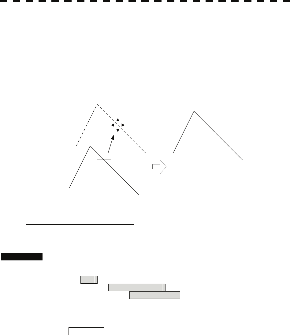
4 Move the cursor mark to the destination, and press the [ENT] key.
The selected mark or line is moved to the destination.
To move another mark or line, repeat procedures 3 and 4.
5 When finished with the correction of lines and marks, press the [0] key.
The cursor mode changes to the normal operation mode, terminating the user map move
mode.
(Example)
Deleting a mark or line (Delete)
With regard to the created user map, a mark or line is deleted individually.
Procedures 1 Open the Edit User Map menu by performing the following menu
operation.
Plot
→ 2. Mark Operations
→ 2. Edit User Map
2 Press the [4] key.
The user map delete mode is selected.
Delete Map is displayed in the cursor mode (upper right of the display on page 2-3).
3 Put the cursor on a mark or line, and press the [ENT] key.
The selected mark or line is deleted.
To delete another mark or line, repeat procedures 3.
4 When finished with the correction of lines and marks, press the [0] key.
The cursor mode changes to the normal operation mode, terminating the user map delete
mode.
3-61
3
3.6 Display User Map y
y y
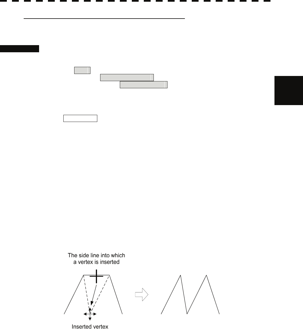
Inserting a vertex into a line (Insert / Move Vertex)
With regard to the created user map, a vertex is inserted into a line.
Procedures 1 Open the Edit User Map menu by performing the following menu
operation.
Plot
→ 2. Mark Operations
→ 2. Edit User Map
2 Press the [5] key.
The user map insert / move mode is selected.
Insert/Move is displayed in the cursor mode (upper right of the display on page 2-3).
3 Put the cursor to a side line into which a vertex will be inserted, and
press the [ENT] key.
A vertex is inserted into the selected line, and the cross cursor mark will be displayed.
4 Move the cross cursor mark to the newly inserted vertex, and press the
[ENT] key.
To insert another vertex, repeat procedures 3 and 4.
5 When finished with the insertion of all vertices, press the [0] key.
The cursor mode changes to the normal operation mode, terminating the user map insert /
move mode.
(Example)
3-62
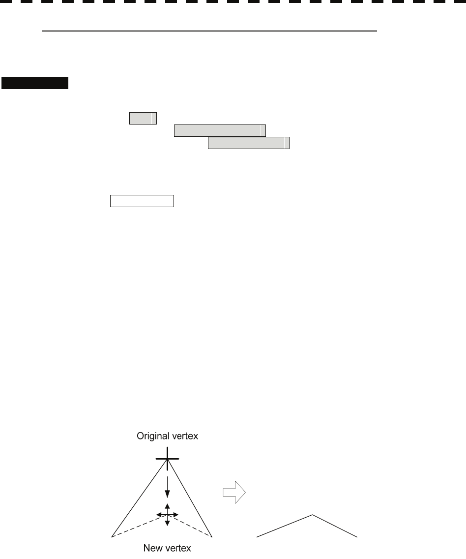
Correcting the mark or vertex of a line (Insert / Move Vertex)
With regard to the created user map, a mark or line is corrected.
Procedures 1 Open the Edit User Map menu by performing the following menu
operation.
Plot
→ 2. Mark Operations
→ 2. Edit User Map
2 Press the [5] key.
The user map insert / move mode is selected.
Insert / Move is displayed in the cursor mode (upper right of the display on page 2-3).
3 Put the cursor on the mark or vertex of a line, and press the [ENT] key.
When the mark or vertex of a line to be corrected is selected, the cross cursor mark will
appear.
4 Move the cross cursor mark to the destination, and press the [ENT] key.
The vertex of the selected mark or vertex of a line is moved to the destination.
To correct another mark or vertex of a line, repeat procedures 3 and 4.
5 When finished with the correction of all vertices, press the [0] key.
The cursor mode changes to the normal operation mode, terminating the user map insert /
move mode.
(Example)
3-63
3
3.6 Display User Map y
y y
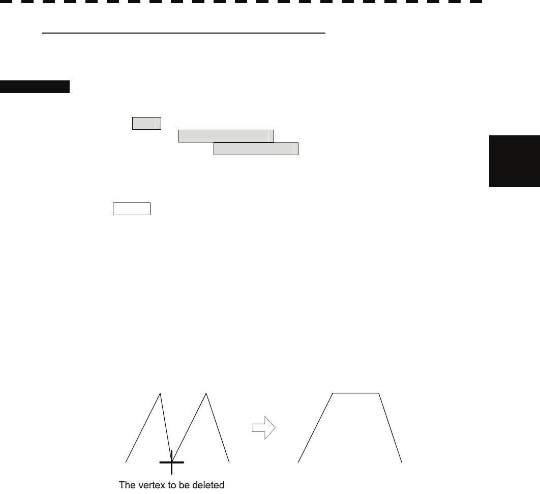
Deleting a mark or vertex of a line (Delete Vertex)
With regard to the created user map, a vertex is deleted individually from a mark or line.
Procedures 1 Open the Edit User Map menu by performing the following menu
operation.
Plot
→ 2. Mark Operations
→ 2. Edit User Map
2 Press the [6] key.
The user map delete mode is selected.
Delete is displayed in the cursor mode (upper right of the display on page 2-3).
3 Put the cursor on the mark or vertex of a line, and press the [ENT] key.
The vertex of the selected mark or vertex of a line is deleted.
All of the lines drawn by joining two points are deleted.
To delete another mark or vertex of a or line, repeat procedure 3.
4 When finished with the correction of all vertices, press the [0] key.
The cursor mode changes to the normal operation mode, terminating the user map delete
mode.
(Example)
3-64
Batch clearing marks or lines (Clear by Type by Color)
With regard to the created user map, marks or lines are batch cleared by type or by color.
Procedures 1 Open the Edit User Map menu by performing the following menu
operation.
Plot
→ 2. Mark Operations
→ 2. Edit User Map
2 Press the [7] key to select the type of marks or lines to be deleted.
Select the type of marks or lines to be deleted.
To select all types, select All .
For example, to delete "red ○" marks, select ○ .
3 Select the color of the marks or lines to be deleted.
Select the color of marks or lines to be deleted.
To select all colors, select All .
For example, to clear "red ○" marks, select Red .
After the items have been selected, Confirmation Window will appear.
4 Press the [1] key.
Selected marks or lines will be batch cleared.
Note: If data is not copied on the flash memory card (option), the data is not be reloaded.
3-65
3
3.6 Display User Map y
y y
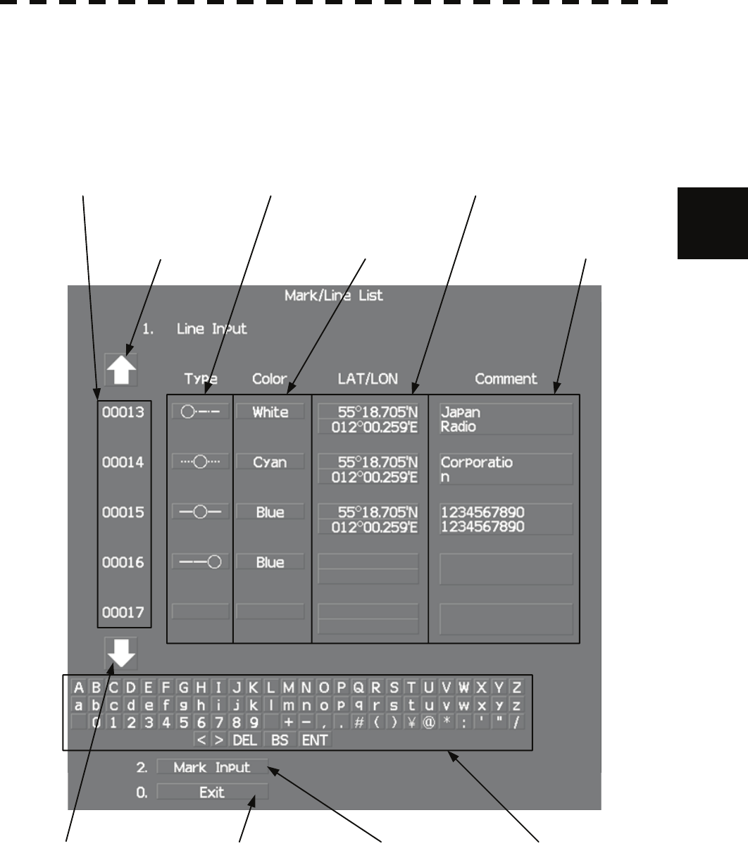
3.6.4 Edit Mark / Line List (Mark / Line List)
With regard to the created user map, it is possible to display the mark / line list, add and edit marks and
lines, and also add comments.
When editing a line, a line extending from the changed vertex to the previous point can be changed.
Comments for
mark / line vertex
Latitude / longitude of
mark / line vertex
Mark color / line color
Mark / line vertex number
Character inputMark / line list switchExit
Mark font / line pattern
Mark / line list scroll
Mark / line list scroll
3-66
Procedures 1 Open the Mark Operations menu by performing the following menu
operation.
Plot
→ 2. Mark Operations
2 Press the [STBY] key.
The transmission standby state is selected.
3 Press the [5] key.
The Mark/Line Entry menu will appear.
4 Select an item to be edited.
For batch entry, select whether to enter the latitude / longitude and comments. For new
entry, select LAT / LON or LAT / LON + Comment .
LAT / LON : Latitude / longitude can be entered.
Comment : Comments can be entered.
LAT / LON + Comment : Both latitude / longitude and comments can be
entered.
5 Press the [6] key.
The Mark/Line List menu will appear.
This window cannot be opened in the transmission state.
3-67

3
3.6 Display User Map y
y y
Creating marks and lines
Procedures 1 Open the Mark / Line List menu.
2 Press the [2] key to select the mark list or line list.
The Mark Input menu and the Line Input menu are switched.
3 Press the [1] key.
The input list will appear.
4 Turn the [MULTI] dial to show a vacant number in reverse video.
Holding down the [RANGE + / - ] key for at least two seconds will enable scroll.
Even if a mark or line is created for a vacant number, the created mark or line is listed at
the end of the current mark / line list.
5 Press the [MULTI] dial.
The list of the mark font or the line pattern will be displayed.
6 Press numeric keys corresponding to the desired mark font or the line
pattern.
The desired mark font or line pattern is selected.
7 In the same manner, enter the color of the mark or line, latitude /
longitude, and comments.
Use the numeric keys, latitude / longitude input screen, and the character input screen for
entry.
For the input method on the latitude / longitude and character input screens, see Section
3.3.4.
To create another mark or line, repeat procedures 2 to 5.
3-68

Adding a line
With regard to the created user map, a vertex is added to the end of the line.
Procedures 1 Open the input list for the Mark / Line List menu.
2 Press the [2] key to select the line list.
The Mark Input menu and the Line Input menu are switched.
3 Press the [1] key.
The input list will appear.
4 Turn the [MULTI] dial to show the number for the end point of a desired
line ……○ in reverse video.
Holding down the [RANGE + / - ] key for at least two seconds will enable scroll.
5 Press the [MULTI] dial.
The list of the line pattern will be displayed.
6 Press numeric keys corresponding to the desired line type.
The previous end point of the line is changed to the midpoint and a new end point is
added.
7 In the same manner, enter the color of the mark or line, latitude /
longitude, and comments.
Use the numeric keys, latitude / longitude, and the character input screen for entry.
For the input method on the latitude / longitude and character input screens, see Section
3.3.4.
To add another line, repeat procedures 2 to 5.
3-69

3
3.6 Display User Map y
y y
Editing a mark or line
Procedures 1 Open the input list for the Mark / Line List menu.
2 Press the [2] key to select the mark list or line list.
The Mark Input menu and the Line Input menu are switched.
3 Press the [1] key.
The input list will appear.
4 Turn the [MULTI] dial to show the number for a mark or line to be
changed in reverse video.
Holding down the [RANGE + / - ] key for at least two seconds will enable scroll.
5 Press the [MULTI] dial.
The list of the mark font or line type will be displayed.
6 Press numeric keys corresponding to the desired mark font or line
pattern.
The mark font or line type is changed.
7 In the same manner, enter the color of the mark or line, latitude /
longitude, and comments.
Use the numeric keys, latitude / longitude, and the character input screen for entry.
For the input method on the latitude / longitude and character input screens, see Section
3.3.4.
To edit or add another mark or line, repeat procedures 2 to 5.
3-70

Changing mark / line list items individually
Procedures 1 Open the input list for the Mark / Line List menu.
2 Press the [2] key to select the mark list or line list.
The Mark Input menu and the Line Input menu are switched.
3 Press the [1] key.
The input list will appear.
4 Turn the [MULTI] dial to display the vertex of a mark or line to be
changed.
Holding down the [RANGE + / - ] key for at least two seconds will enable scroll.
5 Put the cursor on the item to be changed, and press the [ENT] key.
The list will be displayed or the input can be enabled.
6 Press numeric keys corresponding to the number for the item to be
changed. Alternatively, enter a numeric value and character to be
changed.
Use the numeric keys, latitude / longitude, and the character input screen for entry.
For the input method on the latitude / longitude and character input screens, see Section
3.3.4.
To change another item in the mark / line list individually, repeat procedures 2 to 4.
3-71
3
3.6 Display User Map y
y y
3.6.5 Correct Position on User Map (Shift User Map)
If the display position on the user map is different from an actual position, it can be changed to the
correct position in manual mode.
Correcting the display position on the user map (Shift)
Procedures 1 Open the Mark Operations menu by performing the following menu
operation.
Plot
→ 2. Mark Operations
2 Press the [3] key.
Shift is displayed in the cursor mode (upper right of the display on page 2-3) and the
user map shift mode is activated.
3 Put the cursor on a mark or end of a line, and press the [ENT] key.
4 Put the cursor on the point to be corrected, and press the [ENT] key.
Positions of all marks and lines currently displayed will be corrected.
At this time, Map Shift is displayed in the map position correction (lower right of the
display on page 2-4), indicating that the position is being corrected.
Clearing the corrected user map to its original state (Shift Clear)
Procedures 1 Open the Mark Operations menu by performing the following menu
operation.
Plot
→ 2. Mark Operations
2 Press the [4] key.
Shift Clear Confirmation window will appear.
3 Press the [1] key.
Corrected data will be cleared, and the data will be displayed at its original position.
At this time, Map Shift is not displayed in the map position correction (lower right of
the display on page 2-4).
3-72
3.6.6 Operate User Map File (File Operations)
[I] Loading navigation data (Load User Map)
Procedures 1 Insert a flash memory card into the card slot.
Flash memory card (option) is necessary.
For the insertion and removal of the card, see HOW TO INSERT AND REMOVE A
CARD in the appendix.
2 Open the File Operations menu by performing the following menu
operation.
Plot
→ 1. Mark Setting
→ 3. File Operations
3 Press the [1] key to select a card slot.
Slot1 and Slot2 of the Select Card Slot items are switched.
4 Press the [2] key to select Add or Overwrite.
Add and Overwrite of the Load Mode items are switched.
When Add is selected, new data is added to the saved data. When Overwrite is
selected, the saved data is overwritten.
5 Press the [3] key.
The list of navigation data saved in the system will be displayed.
6 Press numeric keys corresponding to the file to be loaded.
Confirmation Window will appear.
7 Press the [1] key.
The selected navigation data will be loaded and displayed of the display.
[II] Discarding navigation data (Unload User Map)
Procedures 1 Open the File Operations menu by performing the following menu
operation.
Plot
→ 1. Mark Setting
→ 3. File Operations
2 Press the [4] key.
Unload Confirmation Window will appear.
3 Press the [1] key.
The saved navigation data will be discarded.
3-73

3
3.6 Display User Map y
y y
[III] Saving navigation data (Save User Map)
Navigation data can be saved when navigation equipment is connected, or the own ship
position on the user map is entered in the manual mode.
Procedures 1 Insert a flash memory card into the card slot.
Flash memory card (option) is necessary.
For the insertion and removal of the card, see HOW TO INSERT AND REMOVE A
CARD in the appendix.
2 Open the File Operations menu by performing the following menu
operation.
Plot
→ 1. Mark Setting
→ 3. File Operations
3 Press the [1] key to select a card slot.
Slot1 and Slot2 of the Select Card Slot items are switched.
4 Press the [5] key.
The Input File Name menu will appear.
5 Enter the file name to be saved.
Up to 10 characters can be entered.
For the input method on the character input screen, see Section 3.3.4.
After the data has been entered, Confirmation Window will appear.
6 Press the [1] key.
Navigation data currently being displayed is saved.
3-74
[IV] Clearing the saved navigation data (Erase User Map)
Procedures 1 Insert a flash memory card into the card slot.
Flash memory card (option) is necessary.
For the insertion and removal of the card, see HOW TO INSERT AND REMOVE A
CARD in the appendix.
2 Open the File Operations menu by performing the following menu
operation.
Plot
→ 1. Mark Setting
→ 3. File Operations
3 Press the [1] key to select a card slot.
Slot1 and Slot2 of the Select Card Slot items are switched.
4 Press the [6] key.
The Erase screen will appear.
The list of navigation data saved in the card will be displayed.
5 Press numeric keys corresponding to the number for the file to be
erased.
Confirmation Window will appear.
6 Press the [1] key.
The selected navigation data is erased and the name of the file is deleted from the list.
3-75

3
3.6 Display User Map y
y y
[IV] Displaying saved navigation data (Card Mark Display)
Procedures 1 Insert a flash memory card into the card slot.
Flash memory card (option) is necessary.
For the insertion and removal of the card, see HOW TO INSERT AND REMOVE A
CARD in the appendix.
2 Open the File Operations menu by performing the following menu
operation.
Plot
→ 1. Mark Setting
→ 3. File Operations
3 Press the [1] key to select a card slot.
Slot1 and Slot2 of the Select Card Slot items are switched.
4 Press the [6] key.
The Card Mark Display menu will appear.
The list of navigation data saved in the card will be displayed.
5 Press numeric keys corresponding to the number for the file to be
displayed.
Confirmation Window will appear.
6 Press the [1] key.
The selected navigation data will be displayed.
3-76
3.6.7 Set and Display Geodetic System (Geodetic)
To create navigation information, set the geodetic system that is used with the connected navigation
equipment. When navigation information is loaded, the geodetic system used when the navigation
information was saved, is displayed. Make sure that the displayed geodetic system is identical to the one
used with the navigation equipment. If the two geodetic systems are different, the positions of navigation
information of the display will be shifted. Therefore, it is important to set the geodetic system of the
navigation equipment.
Setting the geodetic system for navigation data to be saved (Geodetic)
Procedures 1 Open the Geodetic menu by performing the following menu operation.
Plot
→ 2. Mark Operations
→ 7. Geodetic
The numeric value input screen for Geodetic will appear.
2 Enter the desired geodetic system number. (See the section 3.4.20
Geodetic System List)
The geodetic system is determined.
For how to input numeric value on the numeric value input menu, see Section 3.3.4.
By turning the [MULTI] dial, the geodetic system number can be changed.
Displaying the geodetic system of the navigation data being displayed
(Geodetic)
Procedures 1 Load navigation data by referring to Section " [I] Loading navigation
data" on page 3-66.
2 Open the Mark Operations menu by performing the following menu
operation.
Plot
→ 2. Mark Operations
The geodetic system will be displayed in the Geodetic field.
3-77
3
3.8 Use Route Function y
y y
3.7 USE ROUTE FUNCTION
In this radar system, a destination mark set by navigation equipment can be displayed and a simple route
can be created, displayed, loaded and saved. (To use this function, navigation equipment must be
connected to this system)
A plotter unit (option) is required to create, display, load and save the simple route.
If radar video is poor visibility caused by route function, click the Map button to turn off the Map
function. Otherwise, press the [DATA OFF] key to map displays temporarily off.
3.7.1 Display Destination Mark (NMEA Waypoint Display)
A destination mark sent from the external navigation equipment can be displayed.
Procedures 1 Open the Plot menu by performing the following menu operation.
Plot
2 Press the [7] key.
The NMEA Waypoint Display is turned on or off.
Off : Destination is not displayed.
On : Destination is displayed.
When On is selected, the ○WP mark appears of the display.
The destination mark is displayed only when Waypoint data is received from outside by
the NMEA sentence (RMB,BWC,BWR).
3-78
3.8 APPLIED OPERATIONS
3.8.1 Set Radar Signal Processing (Process Setting)
This function enables the setting of detail information about radar signal processing.
Procedures 1 Press the [RADAR MENU] key twice.
2 Open the Process Setting menu by performing the following menu
operation.
2. RADAR Menu
→ 1. Process Setting
Detail information about radar signal processing can be set by changing the settings of the
menu items.
Note: After the settings for radar signal processing are changed, small targets may not be displayed or
unwanted waves may not be suppressed. Thus, do not make a significant change in the settings.
[1] Video Latitude
• Select the dynamic range in which receiving signals are to be shown of the display.
• Select Normal in standard, and Wide in rainy weather.
• Narrow clearly displays short-range videos when STC is used in manual mode.
Narrow : Narrows the dynamic range at short range.
Normal : Standard setting
The dynamic range varies depending on the actual range.
Short distance : wide Long distance : narrow
Wide : Use this mode when rainy weather intensifies unwanted waves.
The dynamic range is about twice as wide as when Normal is selected.
Super Wide : Use this mode when rain cloud remain at Wide mode.
[2] Video Noise Rejection
• This function rejects signals that assumed as noise and clutter in radar videos.
• Select Off to display radar videos like analog signals.
• Select Level1 or Level2 to suppress noise and clutter.
• Select Level1 or Level2 to superimpose-display the chart.
Off : Turns off the noise rejection function, and displays all signals.
Targets are popped up from noise and displayed like analog signals.
Level1 : Rejects the signals of definitely unwanted waves (noise and clutter).
When detection of targets or unwanted waves is not definite, the signals
are displayed.
When detection of targets is definite, the signals are displayed.
Level2 : Rejects the signals of definitely unwanted waves (noise and clutter).
When detection of targets or unwanted waves is not definite, the signals
are rejected.
Only when detection of targets is definite, the signals are displayed.
3-79
3
3.8 Applied Operations y
y y
[3] AUTO Dynamic Range
• When the automatic sea clutter suppression mode and the automatic rain / snow clutter suppression
mode are in use, the dynamic range is automatically controlled.
• When the automatic sea clutter suppression mode is in use, this function improves gain by widening
the dynamic range of only areas where sea clutter is strong and narrowing the dynamic range of areas
where sea clutter is not detected.
• When the automatic rain / snow clutter suppression mode is in use, this function improves gain by
widening the dynamic range of areas where sea clutter and rain / snow clutter are strong and narrowing
the dynamic range of the other areas.
• Land videos become obscure when the automatic rain / snow clutter suppression mode is in use.
Off : Does not control the dynamic range automatically. (Standard setting)
The dynamic range is set in the same manner as when the manual sea clutter
suppression mode or the manual rain / snow clutter suppression mode is in use.
On : Automatically controls the dynamic range.
[4] Process Switch
• This function sets a specific area and switches the video process mode between the inside and outside
of the area.
• In [5] 2nd Process Mode, set the second video process mode for the area outside the boundary.
• In radar video processing (PROC) mode switching (④ lower left of the display on page 2-18), set the
first video process mode for the area inside the boundary.
• Gain at a distance can be improved by supp
• There a e methods fo
ressing near sea clutter through the correlative process.
r two r setting an area.
Off : Disables the Process Switching function. (Standard setting)
Range Fix : Sets a boundary at a constant range from the center.
Set the boundary range in [6] Process Switch Range.
The specific area turns out to be a circle with the own ship’s position as
the center.
AUTO : Automatically sets a specific area.
The area subject to many clutter returns is inside the boundary, and the
area less subject to clutter returns is outside the boundary.
5] 2nd Process Mode[
• Set the second video process mode for the o side of a spec fic area. ut i
• This function is enabled when Range Fix or AUTO is selected in [4] Process Switch.
mo
Video process des.
PROC Off : is mode in general. Select th
3Scan CORREL : Select this mode when many rain / snow clutter returns are
detected.
4Scan CORREL : Select this mode to highlight targets while suppressing sea clutter
returns.
5Scan CORREL : Select this mode to detect small targets hidden by sea clutter
returns.
Remain : Select this mode when own ship yaws wildly.
Peak Hold : Select this mode to detect small targets of which detection
probability is low.
3-80
[6] Process Switch Range
• Set the boundary range of a specific area.
• This function is enabled when Range Fix is selected in [4] Process Switch.
• The specific area turns out to be a circle with the own ship’s position as the center.
• The boundary range can be set in units of 0.1 nm, ranging 0.1 to 25.5 nm.
[7] Fast Target Detection
• This function displays fast moving targets that are suppressed in scan-correlative process mode.
• This function is enabled when 3Scan CORREL , 4Scan CORREL , or 5Scan CORREL is
selected as the video process mode.
• If unwanted waves remain of the display, suppress them by using the [SEA], [RAIN], or [GAIN] dial,
or adjusting the interference rejection mode.
Off : Disables the Fast Target Detection function.
On : Enables the Fast Target Detection function.
3.8.2 Set Radar Trails (RADAR Trails Setting)
This function enables the setting of detail information about radar trails processing.
Procedures 1 Press the [TRAILS] key for 2 seconds.
The RADAR Trails Setting menu will appear.
Detail data about radar trails processing can be set by changing the settings of each menu
item.
Note: After the settings for radar trails processing are changed, targets’ trails may not be displayed or trails
may be plotted with unwanted waves. Thus, do not make a significant change in the settings.
[1] Trails Mode
• Set the radar trail display mode.
• For details on the trail mode, see Section 3.4.8.
[2] Trails Reference Level
•i g radar trails. Select a radar video threshold level required for plott n
• The radar video threshold level increases in order of
Level1 → Level2 → Level3 → Level4 .
• To plot radar trails with unwanted waves, change to a higher level.
• To thin radar trails, change to a higher level.
• If radar trails are plotted in snatches, change to a lower level.
3-81
3
3.8 Applied Operations y
y y
[3] Trails Reduction
• Make a setting for thinning radar trails.
• The effect of thinning increases in order of Level1 → Level2 → Level3 .
• Radar videos do not become obscure because of the thinning of radar trails.
Off : Disables the Trails Reduction function.
Level1 : Enables the Trails Reduction function. (Effect: Low)
Level2 : Enables the Trails Reduction function. (Effect: Middle)
Level3 : Enables the Trails Reduction function. (Effect: High)
[5] Trails Process
• Determine whether to use the video process with radar signals for plotting radar trails.
• When Trails Process is On , radar trails are never plotted with unwanted waves, but the radar trails of
moving targets may not be plotted.
• When Trails Process is Off , radar trails may be plotted with unwanted waves, but the radar trails of
moving targets are always plotted.
Off : Disables the Trails Process function.
On : Enables the Trails Process function.
[6] MAX Interval
• Select the maximum time for displaying radar trails.
• Select Short when short radar trails are often used in bays and the likes.
• Select Super Long when long radar trails are necessary for ocean navigation.
• Continuous trails are available with all the options.
Short : Sets 15 minutes as the maximum time for radar trails display.
Middle : Sets 30 minutes as the maximum time for radar trails display.
Long : Sets 60 minutes as the maximum time for radar trails display.
Super Long : Sets 12 hours as the maximum time for radar trails display.
[7] Trails Erase
• A part of the radar trails can be erased.
• For details on the trail erase, see Section 3.4.9.
8] File Operations[
• For details on the file operations, see Section 3.4.10.
3-82
3.8.3 Set Scanner Unit (TXRX Setting)
This function enables the setting of detail information about an scanner unit.
Procedures 1 Press the [RADAR MENU] key twice.
2 Open the TXRX Setting menu by performing the following menu
operation.
2. RADAR Menu
→ 3. TXRX Setting
Detail information about scanner unit operation can be set by changing the settings of the
menu items.
[1] PRF Fine Tuning
• Fine-tune the transmitting repetition frequency of the transmitter in the range 90 to 100%.
• If radar’s interference patterns are concentrically displayed, increment or decrement the set value by 3
to 4 in order to heighten the effect of interference rejection.
• One of 32 levels 0-31 can be set.
[2] Stagger Trigger
• The interference reduction function is activated by using the transmission repetition frequency control
of the transmitter.
• This function is effective when radar interference does not go away.
Off : Stagger Trigger is not used.
On : Stagger Trigger is used.
[4] PRF
• Select the operation mode the transmitting repetition frequency of the transmitter.
Normal : Standard mode : Both appropriate gain and magnetron’s life
expectancy are maintained.
Economy : Power saving mode : Gain slightly lowers, but the service
life of magnetron is prolonged when short
pulses are used.
High Power : High gain mode : Gain improves when long pulses are used,
but the service life of magnetron is slightly
shortened.
[5] Ice Class Standby Mode
• In this mode, the scanner is rotated when transmission is in the standby state.
• This mode is effective to prevent the antenna's rotating shaft from freezing.
Off : The ice class standby mode is not used.
When transmission is in the standby state, the antenna also stops rotating.
On : The ice class standby mode is used.
When transmission is in the standby state, the antenna rotates.
3-83
3
3.8 Applied Operations y
y y
3.8.4 Set Cursor (Cursor Setting)
This function enables the setting of detail information about EBL / cursor operation and display.
Procedures 1 Press the [RADAR MENU] key twice.
2 Open the Cursor Setting menu by performing the following menu
operation.
5. Sub Menu
→ 9. EBL/Cursor Setting
→ 3. Cursor Setting
Detail information about cursor operation and display can be set by changing the settings
of the menu items.
[1] EBL / VRM Control Cursor
• The EBL / VRM Control Cursor is switched between Valid and Invalid.
• The trackball is provided as a standard device. If the trackball malfunctions, the cursor can be moved
by using the [EBL] dial and [VRM] dial.
• The cursor moves horizontally when [EBL] is operated, and moves vertically when [VRM] is
operated.
• To switch between EBL / VRM operation and cursor operation while On is selected, Press the
[EBL] dial for 2 seconds.
On : Cursor is operated using a [EBL] [VRM] dial.
Off : Cursor is operated using a trackball.
[2] Cursor Length
• Set the length of the cross cursor mark of the display.
Short : Cuts the cross cursor mark in length.
Long : Makes the cross cursor mark twice as long as when Short is selected.
[4] Cursor Pattern
• The type of the cross cursor mark displayed of the display is selected.
: Type 1 is selected for the cross cursor mark 1 displayed in the radar display.
: Type 2 is selected for the cross cursor mark 2 displayed in the radar display.
: Type 3 is selected for the cross cursor mark 1 displayed in the radar display.
: Type 4 is selected for the cross cursor mark 2 displayed in the radar display.
3-84
3.8.5 Set Radar Display (Display Setting)
This system can save combinations of display color and brilliance in accordance with ambient lighting
conditions and the radar display can be easily switched.
Follow the procedures below to set display color and brilliance to be saved before hand.
Setting display color (Display Color Setting)
Procedures 1 Press the [DAY / NIGHT] key for 2 seconds.
The Display Color Setting menu will appear.
[1] Day / Night
• Specify the mode to be changed.
• The following modes are available.
Day1 : Day mode 1 : Used under bright lighting conditions.
Day2 : Day mode 2 : Used under bright lighting conditions.
Day3 : Day mode 3 : Used under bright lighting conditions.
Dusk : Dusk mode : Used under dim lighting conditions.
Night : Night mode : Used under dark lighting conditions.
Setting color of each element
• Specify the color for the element.
• The color for the following elements can be specified.
Outer PPI : The color of the background outside radar video PPI is
selected.
Inner PPI : The color of the background inside radar video PPI is
selected.
Character : The color of the character and bearing scale is selected.
RADAR Video : The color of the radar video is selected.
RADAR Trails (Time) : The color of the time radar trails is selected.
Target Symbol : The color of the target symbol is selected.
Cursor : The color of the cursor is selected.
Range Rings : The color of the range rings is selected.
EBL / VRM / PI : The color of the EBL / VRM / PI is selected.
Own Symbol / HL / Vector : The color of the own ship symbol, heading line, own
ship vector is selected.
Note: Those selected colors can be saved for each Day / Night mode.
3-85
3
3.8 Applied Operations y
y y
Setting display brilliance (Brilliance Setting)
Procedures 1 Press the [RADAR MENU] key twice.
2 Open the Brilliance Setting menu by performing the following menu
operation.
5. Sub Menu
→ 2. Brilliance Setting
Setting brilliance of each element
• Specify the brilliance for the element.
• Level4 indicates maximum brilliance and Level1 indicates minimum brilliance.
• The brilliance for the following elements can be specified.
RADAR Video : The brilliance of the radar video is selected.
RADAR Trails : The brilliance of the radar trails is selected.
Target Symbol : The brilliance of the target symbol is selected.
Range Rings : The brilliance of the range rings is selected.
EBL / VRM / PI : The brilliance of the EBL / VRM / PI is selected.
Character : The brilliance of the character and bearing scale is
selected.
Own Symbol / HL / Vector : The brilliance of the own ship symbol, heading line, and
own ship vector is selected.
Keyboard : The brilliance of the operation panel is selected.
Note: Those selected brilliance can be saved for each Day / Night mode.
Setting radar video brilliance (VID)
The brilliance of the video of the display is adjusted.
Procedures 1 Put the cursor on radar video brilliance switching VID (brilliance /
Alarm ③ on page 2-28), and press the [ENT] key to adjust the radar
video brilliance to obtain the best-to-view video.
The brilliance of the radar video can be adjusted on four stages without opening the
Brilliance Setting menu.
Adjust the radar display to obtain the best-to-view video.
3-86
Setting target symbol brilliance (TT)
The brilliance of the target symbol of the display is adjusted.
Procedures 1 Put the cursor on tracked target / AIS target symbol brilliance switching
TT (brilliance / Alarm ④ on page 2-28), and press the [ENT] key to
adjust the brilliance of the target symbol to obtain the best-to-view
video.
The brilliance of the target symbol can be adjusted on four stages without opening the
Brilliance Setting menu.
Adjust the radar display to obtain the best-to-view video.
3.8.6 Adjust Sound Volume (Buzzer Volume)
When an alarm is activated, the operation panel issues an alarm audible to inform user of the change of
the condition.
The alarm sound can be adjusted by performing the following procedures.
Procedures 1 Press the [RADAR MENU] key twice.
2 Open the Buzzer Volume menu by performing the following menu
operation.
5. Sub Menu
→ 5. Buzzer Volume
• The volume of the alarm sound can be specified for each cause for alarm.
• Level4 indicates maximum volume and Level1 indicates minimum volume.
Key ACK : The operation key acknowledgement is set.
OPE Miss : The incorrect operation alarm is set.
CPA / TCPA Alarm : The dangerous ship alarm is set.
New Target Alarm : The automatic acquisition target alarm is set.
Lost Alarm : The target lost alarm is set.
Navigation Alarm : The navigation data abnormality alarm is set.
System Alarm : The system abnormality alarm is set.
Inter Switch : The inter switch switching alarm is set.
3-87
3
3.8 Applied Operations y
y y
3.8.7 Set User Keys [USER KEY 1 / 2]
Users can freely make settings with [USER KEY1] key and [USER KEY2] key.
By using the keys, users can open a frequently used menu by only single operation, or assign special
functions, to the user key switches.
[I] Initial Setting (User Key Setting)
Set functions that can be performed with the user key switches.
Procedures 1 Press the [RADAR MENU] key twice.
2 Open the User Key Setting menu by performing the following menu
operation.
5. Sub Menu
→ 4. User Key Setting
This system provides two user keys: [USER KEY1] and [USER KEY2]. Different functions can be
allocated to each key.
Functions that can be allocated to each key are as follows:
Menu : A specific menu is directly displayed.
Zoom : The zoom display function is switched between on and off.
[II] Using User Keys (Directly displaying a specified menu)
Preset the menu that is to be displayed with the user key switch.
Procedures 1 Make the initial setting for the user key to Menu .
Make settings in accordance with Section [I] Initial Setting (User Key Setting).
2 Perform the general menu open procedure to open the menu that is to
be directly displayed with User Key.
3 While the menu is open, Press the [USER KEY1] key or [USER KEY2]
key for 2 seconds.
The menu currently being displayed is saved for the pressed user key.
Directly displaying the menus assigned to the User Keys
Procedures 1 Press the [USER KEY1] key or the [USER KEY2] key.
The menu set for the pressed user key will open.
Subsequently, general menu operation can be performed.
3-88

[III] How to use the User key (Zoom Display)
Preset whether to execute the zoom display by operating the user key.
Procedures 1 Make the initial setting for the user key to Zoom .
Make settings in accordance with Section [I] Initial Setting (User Key Setting).
Executing zoom display
Procedures 1 Press either [USER KEY1] key or [USER KEY2] key for which Zoom
has been set.
The zoom mode is activated.
2 Put the cursor on a location that is to be zoomed, and press the [ENT]
key.
Zoom is set.
Cancellation 1 Press either [USER KEY1] key or [USER KEY2] key for which Zoom
has been set.
The zoom mode is cancelled and a normal display will appear.
3-89
3
3.8 Applied Operations y
y y
3.8.8 Set Navigation Data Display (Multi Window Setting)
By performing the following operation, it is possible to display navigation data of the wind direction /
velocity, water depth and the like, as a graph of the display.
Procedures 1 Press the [RADAR MENU] key twice.
2 Press the [3] key.
The Multi Window Setting menu will appear.
Detailed settings of the display are possible by changing the settings of each item.
[1] DIR / DIST EXP Display
• Determine whether to expand the value display of cursor, EBL, and VRM.
• The value display is expanded in digital information area 2.
• When the cursor mark moves on the PPI, the display of cursor information is expanded.
• When an EBL or VRM is operated, the value display of each marker is expanded.
• While the menu is open, any display is not expanded.
Off : Does not expand any display.
On : Expands the display in digital information area 2.
The expanded display remains for 5 seconds after the operation of each
marker, and then it will disappear.
Always On : Expands the display in digital information area 2.
[2] Numeric NAV INFO
• navigation information. Determine whether to display the numeric values of received
• One of two digital information areas is used to display data.
• When navigation data is displayed, the sizes of the target tracking (TT) / AIS information areas are
exclusively decreased.
• Navigation information of the water depth, water temperature, tidal current, wind direction / speed, and
destination is displayed with numeric values.
• Put the cursor on the digital information display Target (menu ① on page 2-27), and press the
[ENT] navigatiokey. The n data display function is switched between on and off.
Off : Does not display the numeric values of navigation information.
Area1 : Displays the numeric values of navigation information in digital information
area 1.
Area2 : Displays the numeric values of navigation information in digital information
area 2.
3-90
[3] Depth Graph Setting >
• The Depth Graph Setting menu will appear.
[1] Depth Graph Display
• Determine whether to display received water depth information with a graph.
• One of two digital information areas is used to display data.
• When the water-depth graph is displayed, the sizes of the target tracking (TT) / AIS information areas
are exclusively decreased.
• Put the cursor on the digital information display Target (menu ① on page 2-27), and press the
[ENT] key. The water-depth graph display function is switched between on and off.
Off : Does not display a water depth graph.
Area1 : Displays the water depth graph in digital information area 1.
Area2 : Displays the water depth graph in digital information area 2.
[2] Depth Range
• Select the depth range on the water depth graph.
50m : Sets 50 m as the depth range.
100m : Sets 100 m as the depth range.
250m : Sets 250 m as the depth range.
AUTO : Uses the depth range in the DPT sentence included in received data.
[3] Time Range
• Select the time range on the water depth graph.
10min : Sets 10 minutes as the time range.
15min : Sets 15 minutes as the time range.
30min : Sets 30 minutes as the time range.
60min : Sets 60 minutes as the time range.
12hour : Sets 12 hours as the time range.
[4] Depth Unit
• Set the unit of water depth for the water-depth graph.
Feet : The feet is used as the unit of water depth.
Fathom : The fathom is used as the unit of water depth.
Meters : The meter is used as the unit of water depth.
3-91
3
3.8 Applied Operations y
y y
[4] Wind Graph Setting >
• The Wind Graph Setting menu will appear.
[1] Wind Graph Display
• Determine whether to display received wind direction / speed information with a graph.
• One of two digital information areas is used to display data.
• When the wind direction / speed is displayed, the sizes of the target tracking (TT) / AIS information
areas are exclusively decreased.
• Put the cursor on the digital information display Target (menu ① on page 2-27), and press the
[ENT] key. The wind direction / speed graph display function is switched between on and off.
Off : Does not display the wind direction / speed graph.
Area1 : Displays the wind direction / speed graph in digital information area 1.
Area2 : Displays the wind direction / speed graph in digital information area 2.
[2] Wind Speed Unit
• Set the unit of wind speed for the wind direction / speed graph.
m/s : Meters per second are used as the unit of wind speed.
km/h : Meters per hour are used as the unit of wind speed.
kn : Knots are used as the unit of wind speed.
[5] TEMP Graph Setting >
• The TEMP Graph Setting menu will appear.
[1] TEMP Graph Display
• Determine whether to display the graph of the water-temperature data that has been received of the
display.
• One of two digital information areas is used to display data.
• When the water-temperature graph is displayed, the sizes of the target tracking (TT) / AIS digital
information areas are exclusively decreased.
• Put the cursor on the digital information display Target (menu ① on page 2-27), and press the
[ENT] key. The water-temperature graph display function is switched between on and off.
Off : The water-temperature graph is not displayed.
Area1 : The water-temperature graph is displayed in the digital information area 1.
Area2 : The water-temperature graph is displayed in the digital information area 2.
[2] TEMP Graph Color
• Set the color for the water-temperature graph.
• There are eight selection items: Color , White , Gray , Blue , Green , Yellow , Pink ,
and Red .
[3] TEMP Range
• When Color is selected for the display color for the water-temperature graph, set the temperature
range of each color.
3-92
[4] Time Range
• Set the time range for the water-temperature graph.
10min : The time range is set at 10 minutes.
15min : The time range is set at 15 minutes.
30min : The time range is set at 30 minutes.
60min : The time range is set at 60 minutes.
12hour : The time range is set at 12 hours.
[6] Course Bar Setting >
• The Course Bar Setting menu will appear.
[1] Course Bar Display
• Determine whether to display the bar graph for the course data that has been received of the display.
• One of two digital information areas is used to display data.
• When the course-bar graph is displayed, the sizes of the target tracking (TT) / AIS information areas
are exclusively decreased.
• Put the cursor on the digital information display Target (menu ① on page 2-27), and press the
[ENT] key. The course bar display function is switched between on and off.
Off : The course bar graph is not displayed.
Area1 : The course bar graph is displayed in the numeric value data area 1.
Area2 : The course bar graph is displayed in the numeric value data area 2.
[2] AUTO Pilot Course
• Determine which field of the APB sentence that has been received is used to display Autopilot (AP)
course.
Course to Steer : The steering angle is displayed.
From ORG : The bearing difference from the original point is displayed.
From CURR POSN : The bearing difference from own ship is displayed.
[3] ROT Scale
• Set the cale fmaximum s or the TURN Rate graph.
30-0-30 : The scale is set at ±30°/min.
60-0-60 : The scale is set at ±60°/min.
90-0-90 : The scale is set at ±90°/min.
120-0-120 : The scale is set at ±120°/min.
150-0-150 : The scale is set at ±150°/min.
300-0-300 : The scale is set at ±300°/min.
3-93

3
3.9 Use Function Key y
y y
3.9 USE FUNCTION KEY [FUNC]
“Radar Function Setting” is provided for easily obtaining the best radar video by saving complex radar signal
processing settings in the optimum status by use, and calling the setting in accordance with the conditions for
using the function.
Functions are factory-set for general use, and the settings can be fine adjusted by operating the menu.
Four function modes are available, and they are factory-set as follows:
Function 1 : Coast Useful for observing short-range videos.
Function 2 : Deepsea Suitable for general ocean navigation.
Function 3 : Fishnet Useful for small target.
Function 4 : Storm Useful for observing videos in stormy weather.
3.9.1 Operation Procedures [FUNC]
Calling a Function
Procedures 1 Press the [FUNC] key.
Each time the [FUNC] key is pressed, the selection changes cyclically as follows.
Function Off → Function 1 → Function 2 → Function 3 → Function 4 → Function Off
The name of the current function mode is displayed in the function (FUNC) mode
switching ( lower left of the display ⑤ on page 2-18).
Alternatively, put the cursor on the function (FUNC) mode switching, and press the
[ENT] key to conduct the same operation as the above.
Changing Function Setting (temporary change)
• When radar signal processing setting is changed by using the menu or button of the display w
function 1 to 4 is called, the change is temporarily reflected to the operating state.
hile
• Since this method does not change the memory contents, the new setting is discarded as soon as
another function is called.
• When the previous function is called again, operation is performed according to the memory
contents.
Changing Function Setting (memory contents change)
• To change the memory contents of functions 1 to 4, use the function setting menu.
• For how to operate the function setting menu, see Section 3.9.3.
3-94
3.9.2 Function Setting Menu Items (User Function Setting)
The function setting menu has the items below.
Page 1
Page 2
1. Pulse Length 0.75NM Standard pulse length of 0.75 NM range SP1 / MP1
2. Pulse Length 1.5NM Standard pulse length of 1.5 NM range SP1 / MP1 / MP2 / MP3
3. Pulse Length 3 / 4NM Standard pulse length of 3 NM range MP1 / MP2 / MP3 / LP1
4. Pulse Length 6 / 8NM Standard pulse length of 6 NM range MP1 / MP2 / MP3 / LP1 / LP2
5. Pulse Length 12NM Standard pulse length of 12 NM range MP1 / MP2 / MP3 / LP1 / LP2
6. Pulse Length 16NM Standard pulse length of 16 NM range MP1 / MP2 / MP3 / LP1 / LP2
1. Mode Name of the mode to be used Coast / Deepsea / ・・・・
2. IR Radar interference rejection Off / Low / Middle / High
3. Process Video process PROC Off / 3Scan CORREL / ・・・・
4. Target Enhance Target enhance Off / Level1 / Level2 / Level3
5. AUTO STC/FTC Automatic clutter suppression Off / AUTO Sea / AUTO Sea/Rain
6. Save Present State Saving of the present state
Page 3
1. Video Latitude Dynamic range of radar video Narrow / Normal / Wide / Super Wide
2. Video Noise Rejection Radar video noise rejection Off / Level1 / Level2
3. AUTO Dynamic Range Automatic dynamic range control Off / On
4. Process Switch Radar video process switching Off / Range FIX / AUTO
5. 2nd Process Mode Second video process mode PROC Off / 3Scan CORREL / ・・・・
6. Process Switch Range Video process switching range Range setting
7. Fast Target Detection Fast moving target detection Off / On
Page 4
Page 5
1. Gain Offset Gain correction Correction value setting
2. PRF Pulse repetition frequency Normal / Economy / High Power
3. Small Buoy Detection Small target detection mode Off / On
4. Fishnet Detection Fishnet detection mode Off / On
5. Antenna Height Antenna height Default / -5m / 5-10m / 10-20m / 20m-
1. Trails Interval Radar trails length Off / 15sec / ・・・・
2. Trails Mode Radar trails mode True / Relative
3. Trails Reference Level Radar trails plotting threshold Level1-4
4. Trails Reduction Thinning of radar trails Off / Level1-3
5. Time / All Combine Superimpose-display of time radar
trails and continuous radar trails Off / On
6. Trails Process Radar trails video process Off / On
7. Max Interval Maximum time for radar trails display Short / Middle / Long / Super Long
3-95
3
3.9 Use Function Key y
y y
3.9.3 Overview of Function Operations (User Function Setting)
The following outlines the operation of each function selected from the function setting menu.
Procedures 1 Press the [FUNC] key for 2 seconds.
The User Function Setting menu will appear.
Specify the number for the function for which the settings are to be changed.
The following are the operation overviews of each function setting item.
[Page 1] [1] Mode
• Selects the function name to be indicated at the lower left of the display when the function is selected.
• When the setting is changed back to the factory setting, the initial value of the selected mode is
called.
• The following 11 modes are provided.
Coast : Use this mode to monitor a relatively short range, for example, bays and
coasts where many boats and ships are running. (Importance is attached to
resolution.)
Deepsea : Use this mode to monitor a relatively long range, for example, the open sea.
(Importance is attached to long-range gain.)
Fishnet : Use this mode to detect small targets such as fishnets of round haul netters
hidden by sea clutter returns. (Importance is attached to sea clutter
suppression, and gain to moving targets lowers.)
Storm : Use this mode when many rain / snow clutter returns or sea clutter returns
are detected in stormy weather. (Importance is attached to rain / snow
clutter and sea clutter suppression, and gain slightly lowers.)
Calm : Use this mode when only a few rain / snow clutter returns or sea clutter
returns are detected.
Rain : Use this mode when sea clutter is not strong but rain / snow clutter is
strong. (Importance is attached to rain / snow clutter suppression, and
gain slightly lowers.)
Bird : Use this mode to detect flocks of sea birds.
Long : Use this mode to monitor utmost distances in the broad ocean.
Buoy : Use this mode to detect small targets like radio buoys in areas outside the
sea clutter area. (This mode displays targets of which detection probability
is low.)
User1 : General mode used when the nine modes above are not applicable.
User2 : General mode used when the nine modes above are not applicable.
[Page 1] [2] IR (Interference Rejection)
• Same function as IR described in Section 3.4.1.
[Page 1] [3] Process (Video Process)
• Sa e function as Process described in Section 3.4.4. m
[Page 1] [4] Target Enhance
• Sa e function as Target Enhance described in Section 3.4.3. m
3-96

[Page 1] [5] Auto STC / FTC (Auto Sea / Rain)
• Detects unwanted waves such as rain / snow clutter and sea clutter and automatically suppresses
them.
• When the sea state or weather changes, this function automatically performs suppression processing
in accordance with the situation.
• Suppression processing is not full automatic, and requires the operator to adjust the afterimages of
unwanted waves.
• To adjust the afterimage of sea clutter, use the [SEA] dial.
• To adjust the afterimage of rain / snow clutter, use the [RAIN] dial.
• In areas where the density of unwanted waves is low, unwanted waves may remain being judged as
targets. Thus, use the automatic clutter suppression mode together with the video process mode.
• Characteristics of the automatic clutter suppression function.
Off : Disables the automatic clutter suppression function.
Select off when rain / snow clutter and sea clutter are not strong or when the
ship is in a bay.
AUTO Sea : Automatically detects the strength of sea clutter, and performs the most
suitable sea clutter suppression processing.
Even when the strength of sea clutter varies depending on the wind direction,
ssion processing.
AUTO Sea performs the most suitable suppre
Land like islands can be displayed naturally.
Since rain clouds outside sea clutter areas are recognized as land, there is no
effect of suppressing rain / snow clutter.
AUTO Sea/Rain : Along with AUTO Sea, AUTO Rain automatically detects the strength of
rain / snow clutter, and performs the most suitable rain / snow clutter
suppression processing.
When rain clouds are scattered about, AUTO Rain performs rain / snow
clutter suppression processing for only the rain-cloud areas.
Since land is recognized as rain clouds, land videos become obscure.
[Page 2] [1] - [7] Pulse Length
ange.
• Sets the standard transmitter pulse length in each r
• When the range is called, the pulse range is used.
[Page 3] [1] - [7] Process Setting
• Operation i he same as that of the Process Setting menu described in Section 3.8.1.
s t
[Page 4] [1] - [7] Trails Setting
• Same functions as in the Trails Setting menu described in Section 3.8.2.
3-97
3
3.9 Use Function Key y
y y
[Page 5] [1] Gain Offset
• Corrects gain while the function mode is called.
• Since the displayed noise level varies depending on the combination of the video process mode and
the interference rejection level, gain needs fine adjustment for always obtaining the highest level.
• The gain correction function saves the correction value set by the gain adjust in each function mode,
so it can obtain the highest gain without the gain adjust being operated when the function mode is
changed.
• To set high gain, set a value on the “+” side.
• To set low gain, set a value on the “-” side.
• When the radar interference rejection level is increased, the noise level is lowered. Thus, set a gain
correction value to the “+” side.
• When the video process mode 3Scan CORREL , 4Scan CORREL , or 5Scan CORREL is
used, the noise level is lowered. us, set a ga n correction value to the “+” side. Th i
• When the video process mode Remain or Peak Hold is used, noise is hard to disappear. Thus,
set a gain correction value to the “-” side.
[Page 5] [2] PRF
• Same function as in the Pulse Repetition Frequency described in 3.8.3.
Page 5] [3] Small Buoy Detection[
• When the automatic sea clutter suppression function is used, this mode is used to process signals for
detecting small targets.
Off : Activates the general signal processing mode.
On : The signal processing mode for detecting small targets.
[Page 5] [4] Fishnet Detection
• Use this mode to detect small targets hidden by sea clutter returns.
• The simultaneous use with the automatic rain / snow clutter suppression function will increase effects.
Off : Activates the general signal processing mode.
On : Activates the fishnet detection mode.
[Page 5] [5] Antenna Height
• Set the height of radar antenna above sea level.
• The STC/FTC curve is changed.
-5m : Set the antenna height under 5m.
5-10m : Set the antenna height 5m to 10m.
10-20m : Set the antenna height 10m to 20m.
20m- : Set the antenna height over 20m.
3-98
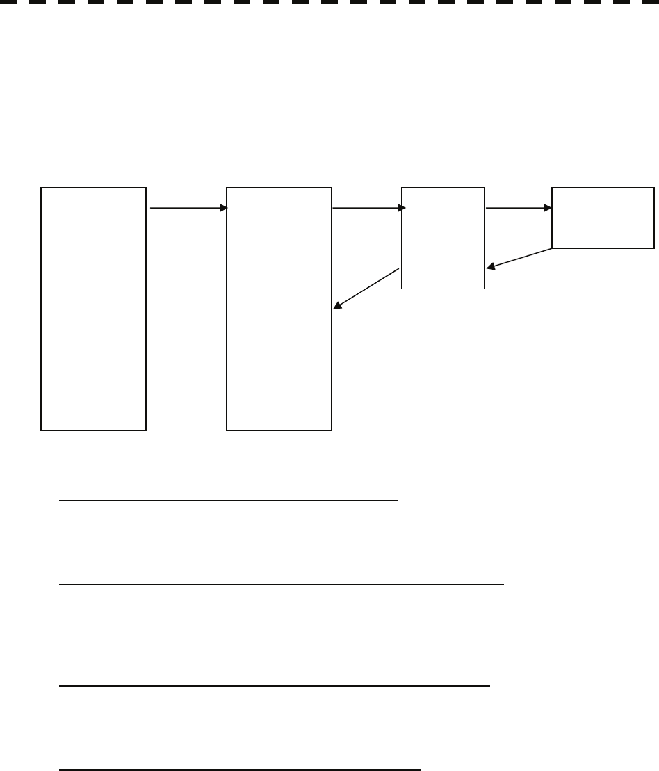
3.9.4 Overview of saved Function Setting Data
The overview of saved function setting data is as follows:
• Factory-set data : Saved data that general operation cannot change
• Default data : Standard data of each function mode that users can change
• Data that can be called : Saved data that can be called by pressing the [FUNC] key
User Function Menu [Page 1] [1] Mode
Coast
Deepsea
Fishnet
Storm
Calm
Rain
Bird
Long
Buoy
User1
User2
Coast
Deepsea
Fishnet
Storm
Calm
Rain
Bird
Long
Buoy
User1
User2
FUNC1
FUNC2
FUNC3
FUNC4
Present
[page5]-[9] [page1]-[1]
[page5]-[8]
[FUNC]
[page1]-[6]
Function Setting Function Setting
Data that can be called
Function Setting
Default data
Factory-set data Current data
• Calls the default value of the mode, and saves it for the function number.
User Function Menu [Page 1] [6] Save Present State
• The currently operating state can be saved for the function number.
• Use this function to save the state of good setting that will be frequently used.
User Function Menu [Page 5] [8] Set Mode Default
• Saves the setting of the current function number, as the default setting of the mode.
User Function Menu [Page 5] [9] Initialize
• Changes the memory contents of the mode, which is used with the current function number, back to
the factory setting.
3-99
3
3.10 Use User Setting y
y y
3.10 USE USER SETTING
The operation status of the radar is recorded. If the system is operated by more than one operator, the
operators can register operation status as suitable for them and call the status. Operation status for up to
five operations can be registered, and a name can be assigned to each status. (Up to 10 alphanumeric
characters)
* Data saved by the user setting
• Display Color Setting menu
• Buzzer Volume
• User Key Setting menu
• Display Style (Date display style)
• EBL / VRM Control CURS
• Cursor Length
3.10.1 Save Operating State (Save User Setting)
The system's current operating state can be saved in the system by performing the operation below.
Procedures 1 Press the [RADAR MENU] key twice.
2 Open the User Setting menu by performing the following menu
peration.
o
5. Sub Menu
→ 3. User Setting
3 ress the [2] key. P
T
he Input File Name menu will appear.
4 Enter the file name to be saved.
The operating state data will be saved.
Up to 10 characters can be entered.
For the input method on the character input screen, see Section 3.3.4.
3-100
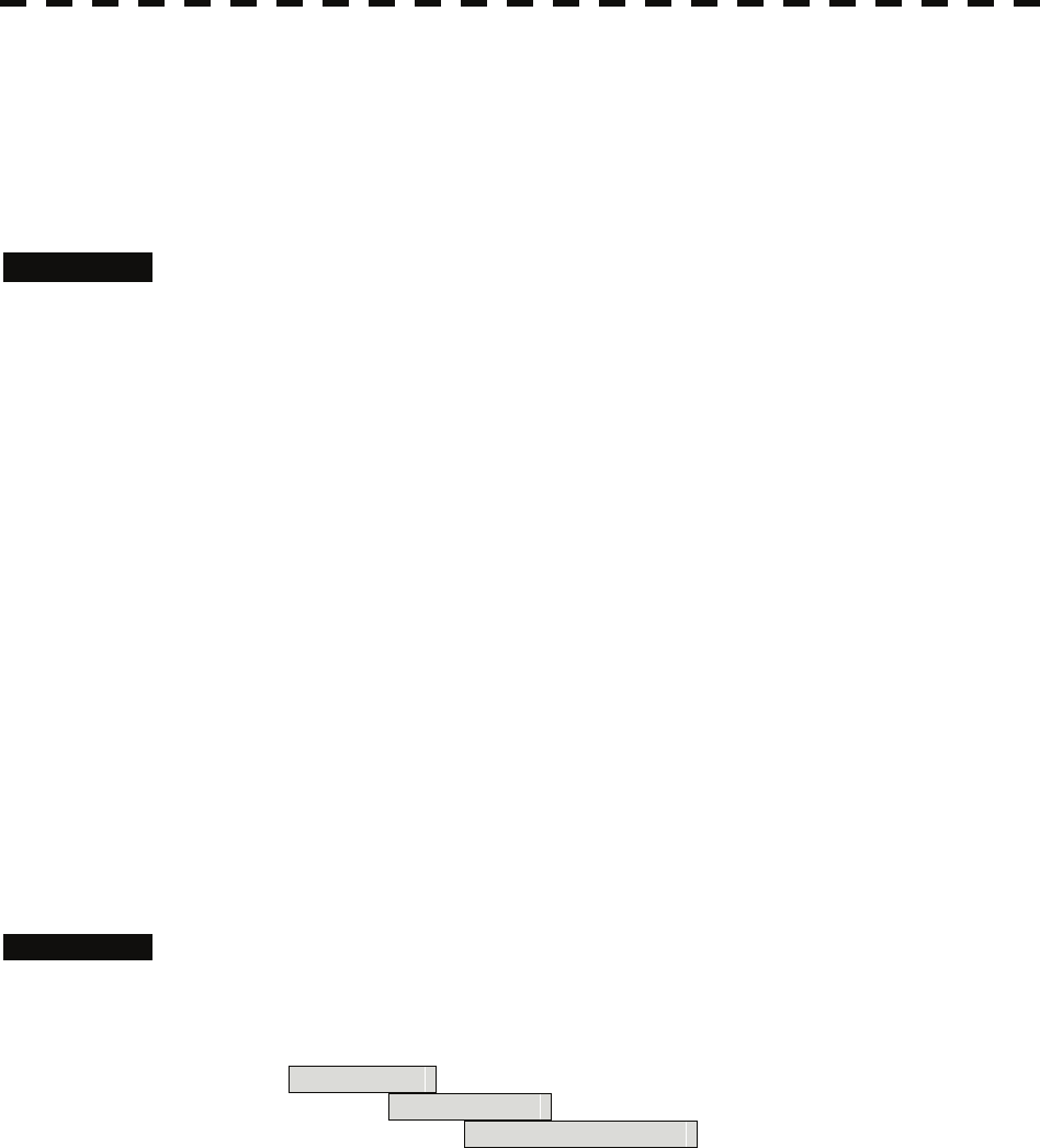
3.10.2 Load Operating State (Load User Setting)
The operating state saved in the system can be loaded by performing the operation below.
When the operating state is loaded, the previous operating state data is discarded. Therefore, if you do not
want to discard the operating state data, save the operating state by performing the operation described in
Section 3.10.1.
Procedures 1 Put the cursor on the display item switching (Brilliance / Alarm ① on
page 2-28), and press the [ENT] key.
The Brilliance menu and the Display INFO menu are switched.
2 Put the cursor on the user setting load (Display information ⑦ on page
2-28), and press the [ENT] key.
The Load User Setting menu will appear.
3 Press numeric keys corresponding to the file to be loaded.
Confirmation Window will appear.
4 Press the [1] key.
The operating state data will be loaded.
3.10.3 Delete Operating State (Delete User Setting)
The operating state saved in the system can be deleted by performing the operation below.
Use this function to delete unnecessary operating state data.
Procedures 1 Press the [RADAR MENU] key twice.
2 Open the Delete User Setting menu by performing the following menu
operation.
5. Sub Menu
→ 3. User Setting
→ 3. Delete User Setting
3 Press numeric keys corresponding to the file to be deleted.
Confirmation Window will appear.
4 Press the [1] key.
The operating state data will be deleted.
3-101

3
3.11 Using Card y
y y
3.11 USING CARD
This radar has two card slots. Inserting a flash memory card (option) into a card slot, you can save the
following contents, saved in the process unit, in the card or can load data from the card to the process
unit.
• Tr f own ship : 7000 points maximum ails o
ack o
ark L 00 poi
connected)
• m (the plotter unit option is necessary)
e
hese pieces of information can be saved in a flash memory card as a file. The internal capacity is as
• Tr f other ship : 20 target×1500 points (the Target Tracking unit, or AIS unit
option is
necessary)
• M ine : 20 nts maximum (20000 items when the plotter unit option is
Waypoint : 999 points maximu
• Rout : 10 routes maximum (the plotter unit option is necessary)
T
large as only a file. An internally created file can be saved until the flash memory card is full.
3.11.1 perate File on the Card (File Manager)
O
Procedures 1 sert a flash memory card into the card slot.
Flash memory card (option) is necessary.
TO INSERT AND REMOVE A
2 ress the [STBY] key.
he transmission standby state is activated.
3 ress the [RADAR MENU] key twice.
4 ress the [1] key.
he File Manager window will appear.
ystem is in the transmission state.
In
For the insertion and removal of the card, see HOW
CARD in the appendix.
P
T
P
P
T
The window will not be open when the s
3-102
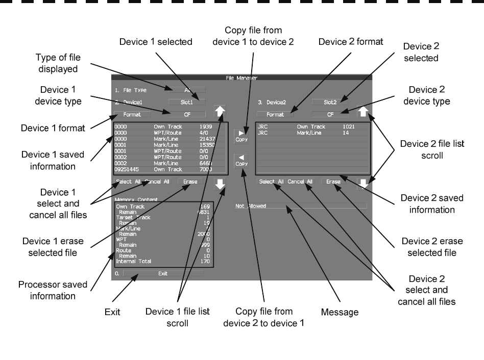
• In mation saved in the process unit is displayed in the Memory Content. for
Own Track : Number of data points for own ship's track (7000 points maximum).
Remain : Number of remaining data points of own ship's track that can be saved.
Target Track : The number of target track (up to 20 targets).
Remain : The remaining number of target track to be saved.
Mark / Line : Number of mark and line points made with user map (up to 2000 items.
20000 items when the plotter unit option is connected).
Remain : Number of remaining data points of marks and lines that can be saved.
WPT : Number of data points of created waypoints (999 points maximum).
Remain : Remaining waypoints that can be saved.
Route : Number of data points of created routes (10 routes maximum).
Remain : Remaining routes that can be saved.
Internal Total : Total number of data points.
• The file name and data saved in the selected device will be displayed.
• Pressing the arrows located upper right and bottom right of the file name list will scroll the list.
3-103
3
3.11 Using Card y
y y
[I] Copy Internal Information to Card (Copy Internal -> Card)
Procedures 1 Press the [2] key while the File Manager menu is open.
Selected items for Device1 will be displayed.
2 Press the [1] key.
Internal is selected.
3 Press the [3] key.
Selected items for Device2 will be displayed.
4 Press numeric keys corresponding to the device to which data is to be
copied.
The list of files saved in the selected device will be displayed.
5 Put the cursor on the data to be copied, and press the [ENT] key.
Pressing the [ENT] key will select the data. Pressing the [ENT] key one more time will
cancel the selection.
6 Put the cursor on Copy , and press the [ENT] key.
The character input screen for the Input File Name menu will appear.
7 Enter the file name to be saved.
Up to 10 characters can be entered.
For the input method on the character input screen, see Section 3.3.4.
After the data has been entered, Confirmation Window will appear.
8 Press the [1] key.
The entered name is written into the selected device as a file name.
Up to the maximum number of items, described on the previous page, can be saved in the
device. With regard to the capacity for saving data, data can be saved on a flash memory
card as a file, and those files can be saved until the flash memory card is full.
3-104
[II] Load Information from Card to Internal Portion (Copy Card -> Internal)
Procedures 1 Press the [2] key while the File Manager menu is open.
Selected items for Device1 will be displayed.
2 Press the [1] key.
Internal is selected.
3 Press the [3] key.
Selected items for Device2 will be displayed.
4 Press numeric keys corresponding to the device in which data to be
loaded is saved.
The list of files saved in the selected device will be displayed.
5 Put the cursor on the data to be copied, and press the [ENT] key.
Pressing the [ENT] key will select the data. Pressing the [ENT] key one more time will
cancel the selection.
6 Put the cursor on Copy , and press the [ENT] key.
Confirmation Window will appear.
7 Press the [1] key to overwrite data, or press the [2] key to add new data.
When Overwrite is selected, internally saved data is deleted and new data is loaded. When
Add is selected, new data is added to the saved data.
8 Press the [1] key.
The selected file is loaded into the system from the card.
When adding data saved on the card to the data saved in the system, data can be copied from multiple
files. However, when the maximum number of units of data is reached, additional data cannot be loaded.
Even in the ADD mode, WPT data and Route data are overwritten.
3-105
3
3.11 Using Card y
y y
[III] Copy Information (Copy)
Procedures 1 Press the [2] key while the File Manager menu is open.
Selected items for Device1 will be displayed.
2 Press numeric keys corresponding to the device from which data is to
be copied.
The list of files saved in the selected device will be displayed.
3 Press the [3] key.
Selected items for Device2 will be displayed.
4 Press numeric keys corresponding to the device to which data is to be
copied.
The list of files saved in the selected device will be displayed.
5 Put the cursor on the data to be copied, and press the [ENT] key.
Pressing the [ENT] key will select the data. Pressing the [ENT] key one more time will
cancel the selection.
6 Put the cursor on Copy , and press the [ENT] key.
The character input screen for the Input File Name menu will appear.
If there is a file having the same name, the file selection window will appear.
When deleting saved data and copying new data, press the [1] key to select Overwrite.
When adding data to a Waypoint file, press the [2] key to select Add. Even in the Add
mode, WPT data and Route data are overwritten. When selection has been made,
Confirmation Window will appear.
7 Enter the file name to be saved.
Up to 10 characters can be entered.
For the input method on the character input screen, see Section 3.3.4.
After the data has been entered, Confirmation Window will appear.
8 Press the [1] key.
The entered name is written into the selected device as a file name.
3-106
[IV] Erase File (Erase)
Procedures 1 Press the [2] key while the File Manager menu is open.
Selected items for Device1 will be displayed.
2 Press numeric keys corresponding to the device in which data to be
erased is saved.
The list of files saved in the selected device will be displayed.
3 Select data to be erased.
Pressing the [ENT] key will select the data. Pressing the [ENT] key one more time will
cancel the selection.
4 Put the cursor on Erase , and press the [ENT] key.
Confirmation Window will appear.
5 Press the [1] key.
The selected file will be erased.
[V] Initializing a card (Format)
Procedures 1 Press the [2] or [3] key while the File Manager is open.
Selected items for Device1 or Device2 will be displayed.
2 Put the cursor on Format for the device to be initialized, and press
the [ENT] key.
Confirmation Window will appear.
3 Press the [1] key.
Initialization will be executed.
[VI] Showing data saved on the card (Show Card)
Procedures 1 Press the [2] or [3] key while the File Manager is open.
Selected items for Device1 or Device2 will be displayed.
2 Press numeric keys corresponding to the device in which data to be
displayed is saved.
The list of files saved in the selected device will be displayed.
[VII] Exit
Exit 1 Press the [0] key.
The File Manager menu will close.
3-107

3
3.12 Display Simple Chart y
y y
3.12 DISPLAY SIMPLE CHART
3.12.1 Display JRC Coastline ROM Card [MAP]
z Insert the JRC coastline ROM card with the top surface upward into card slot 1 (lower) or 2 (upper).
Press the [MAP] key, and the coastlines will be displayed automatically.
z Two JRC coastline ROM cards can be inserted into card slots 1 and 2 at the same time.
z For ranges including detailed coastlines, refer to the Coastline ROM card catalog.
z Do not insert an ERC card (provided by Japan Hydrographic Association) or C-MAP card into a card
slot while JRC Coastline ROM card is in the other slot. Doing so causes display trouble.
Procedures 1 Press the [Map] key while the JRC coastline ROM card is being inserted
into the card slot.
Coastline will be displayed.
For the insertion and removal of the card, see HOW TO INSERT AND REMOVE A
CARD in the appendix.
3.12.2 Display ERC Card [MAP]
z Insert the ERC card (provided by Japan Hydrographic Association) with the top surface upward into
card slot 1 (lower) or 2 (upper). Press the [MAP] key, and the coastlines will be displayed
automatically.
z Two ERC cards can be inserted into card slots 1 and 2 at the same time.
z For ranges of charts to be displayed, refer to the catalog issued by Japan Hydrographic Association.
z Do not insert JRC Coastline ROM card or C-MAP card into a card slot while the ERC card is in the
other slot. Doing so causes display trouble.
Procedures 1 Press the [Map] key while the ERC card is being inserted into the card
slot.
Coastlines will be displayed.
For the insertion and removal of the card, see HOW TO INSERT AND REMOVE A
CARD in the appendix.
3-108
3.12.3 Display JRC Chart on CF Card (SEL JRC ROM Card File)
By copying multiple JRC coastline ROM cards onto a compact flash memory card, this function
selectively displays any two charts among the copied charts. For a ship that sails in the wide range, this
function is convenient because charts can be selected from the menu without alternately inserting JRC
coastline ROM cards.
Note: The copied chart can operate only in the system that originally copied the chart.
The copied chart cannot be operated in other systems. The capacity of the compact flash
memory card to be used is 2GB or less.
[I] Copying a JRC ROM card to a CF card (Copy JRC ROM Card to CF)
Procedures 1 Insert a JRC coastline ROM card into card slot 1 (lower) and insert a
compact flash memory card into card slot 2 (upper).
Flash memory card (option) is necessary.
A PCMCIA (PC card) adapter for the compact flash memory card is necessary to insert a
compact flash memory card.
For the insertion and removal of the card, see HOW TO INSERT AND REMOVE A
CARD in the appendix.
2 Press the [Map] key for 2 seconds.
The Map Setting menu will appear.
3 Open the JRC / ERC Setting menu by performing the following menu
operation.
3. JRC/ERC Setting
→ 9. Next
4 Press the [7] key.
Confirmation Window will appear.
5 Press the [1] key.
Data on the JRC card will be copied onto the compact flash memory card.
6 To copy multiple JRC charts, alternately change JRC coastline ROM
cards and repeat procedures 4 and 5.
3-109

3
3.12 Display Simple Chart y
y y
[II] Selecting a copied JRC chart (SEL JRC ROM Card File)
Procedures 1 Insert a compact flash memory card on which a JRC chart has been
copied into slot 2.
Flash memory card (option) is necessary.
For the insertion and removal of the card, see HOW TO INSERT AND REMOVE A
CARD in the appendix.
2 Press the [Map] key for 2 seconds.
The Map Setting menu will appear.
3 Press the [6] key.
The SEL JRC ROM Card File menu will appear.
4 Press numeric keys corresponding to the desired file to be selected.
The selected file will be shown in reverse video.
Cancelling the selected file
5 Press numeric keys corresponding to the file to be cancelled.
The canceled file name will return to the original normal display.
Note: Up to 2 files of the JRC chart can be selected.
If JRC charts are not copied on the compact flash memory card, the file names is not be
displayed.
3.12.4 Fill Charts (Fill Land Area)
This function fills the chart when JRC / ERC card is in use.
Procedures 1 Press the [Map] key for 2 seconds.
The Map Setting menu will appear.
2 Press the [1] key.
The Fill Land Area function is switched between on and off.
On : Charts are filled.
Off : Charts are not filled.
3-110
3.12.5 Set JRC / ERC Chart Display (JRC / ERC Setting)
This function enables the setting of detail information about chart display.
Procedures 1 Press the [Map] key for 2 seconds.
The Map Setting menu will appear.
2 Press the [3] key.
The JRC / ERC Setting Menu will appear.
Detail information about the colors and brilliance of JRC / ERC chart display can be set
by changing the settings of the menu items.
The data of colors and brilliance can be saved for each day / night mode.
[1] Day/Night
• Select a desired display mode before setting the colors and brilliance of chart display.
• There are 5 selection items: Day1 , Day2 , Day3 , Dusk , and Night .
[2] Color of Land
• Select the color of land display.
• There are 4 selection items: Brown , Yellow , Green , and White .
[3] Bright of Land
• Select the brilliance of land display.
• There are 3 selection items: Low , Middle , and High .
[4] Color of Sea
• Select the color of sea display.
• There are 4 selection items: Gray , Gray , Blue , and Green .
[5] Bright of Sea
•Select the bright of sea display.
• There are 4 selection items: Off , Low , Middle , and High .
[6] Color of Name
• Select the color of a location name.
• There are 8 selection items: Black , White , Gray , Blue , Green , Yellow , Pink ,
and Red .
3-111
3
3.12 Display Simple Chart y
y y
[7] Bright of Name
• Select the brilliance of location name display.
• There are 4 selection items: Off , Low , Middle , and High .
[8] Bright of Track/Mark/Line
• Select the brilliance of track, mark and line.
• There are 4 selection items: Level1 , Level2 , Level3 , and Level4 .
[9] Next
• Moves to the next page.
[1] LAT/LON Line
• Select the mode to display latitude and longitude lines.
• There are 2 selection items:
Line&NUM :Displays both latitude / longitude lines and values indicating the latitude and
longitude.
NUM :Displays only the values indicating the latitude and longitude.
[2] Color of L/L Line
• Select the colors that are to represent latitude and longitude lines.
• There are 8 selection items: Black , White , Gray , Blue , Green , Yellow , Pink ,
and Red .
[3] Bright of L/L Line
• Select the bright of latitude / longitude line display.
• There are 4 selection items: Off , Low , Middle , and High .
[4] ERC Display Request
• Set whe ther to display data saved in the ERC.
On : Data in the ERC is displayed.
Off : Data in the ERC is not displayed.
[5] ERC Mark
• Select t ark dihe size of m splay on the ERC chart.
Normal : The ERC mark is displayed in normal size.
Small : The ERC mark is displayed in a size smaller than normal.
3-112
[6] JRC ROM Card Display
• Sets the display contents of the JRC card.
• The JRC ROM Card Display menu will appear.
[1] Light House
• Determine whether to display lighthouses.
• Set whether to display data saved in the ERC.
On : Light houses are displayed.
Off : Light houses are not displayed.
[2] Buoy
• Determine whether to display buoys.
• Set whether to display data saved in the ERC.
On : Buoys are displayed.
Off : Buoys are not displayed.
[3] Rough Line
• Determine whether to display rough lines.
• Set whether to display data saved in the ERC.
On : Rough lines are displayed.
Off : Rough lines are not displayed.
[4] Other Line
• Determine whether to display other lines.
• Set whether to display data saved in the ERC.
On : Other lines are displayed.
Off : Other lines are not displayed.
3-113
3
3.12 Display Simple Chart y
y y
Setting Contour Lines on JRC Chart (Contour Setting)
Procedures 1 Press the [Map] key for 2 seconds.
The Map Setting menu will appear.
2 Press the [4] key.
The Contour Setting Menu will appear.
Depths and display colors can be set for 9 contour lines in total: 8 for depth specification
and 1 for other depths.
3 Press numeric keys corresponding to the depth for which the settings
are to be changed.
The numeric value input screen for the Contour Setting menu will appear.
4 Enter the depth to be set.
For how to input numeric data on the numeric value input screen, see Section 3.3.4.
After a value has been entered, depth contour setting items will be displayed.
5 Press numeric keys corresponding to the type of the depth contour to
be set.
The type of line for displaying the depth contour corresponding to the depth is set.
6 Select the number of display color to be set, pressing the numeric key.
The selected color to represent the contour lines of the depth will be set.
When Off is selected, the depth contour will not be displayed.
To change the settings of other depths, repeat steps 3 to 6.
JRC ROM card plotting mode (JRC ROM Card Draw Mode)
Procedures 1 Press the [Map] key for 2 seconds.
The Map Setting menu will appear.
2 Press the [8] key.
The JRC ROM Card Draw Modes are switched. If the chart is plotted in segments due to
the [Fast] display mode, change the mode to the [Detailed] mode.
Fast : The chart is displayed quickly.
Detailed : The chart is displayed in detail.
3-114

3.12.6 Display C-MAP Card [MAP]
• Turn off the power supply to the system, insert a C-MAP card into either card slot 1 (lower) or card
slot 2 (upper), and then press the [Map] key. Coastlines will be displayed.
• Be sure to turn off the power supply to the system before inserting or removing a C-MAP card. If a
C-MAP card is inserted or removed with the power supply turned on, a malfunction will occur on the
display.
• When using a compact flash memory type C-MAP card, be sure to use a PCMCIA(PC card) adapter
for the compact flash memory card which is commonly sold at retail outlets.
• Only one C-MAP card can be inserted. If two C-MAP cards are inserted at the same time, a
malfunction will occur on the display.
• With regard to the range of the chart to be displayed, refer to the catalog.
• Do not simultaneously insert a JRC coastline ROM card and an ERC card (issued by Japan
Hydrograp ic Association) into the card slot. A malfunction will occur on the display.
h
Procedures 1 Press the [Map] key while a C-MAP card is being inserted into the card
lot.
s
Coastlines will be displayed.
For the insertion and removal of the card, see HOW TO INSERT AND REMOVE A
CARD in the appendix.
Insert or remove a C-MAP card while the power supply to the system is turned off.
C-MAP display setting (C-MAP Setting)
Procedures 1 Press the [Map] key for 2 seconds.
The Map Setting menu will appear.
2 ress the [2] key. P
T
he C-Map Setting menu will appear.
[1] LAT/LON Line Display
• Set whether to display latitude / longitude lines on the C-MAP.
On : Latitude / longitude lines are displayed.
Off : Latitude / longitude lines are not displayed.
[2] Depth Display
• Set whether to display water depth values on the C-MAP
On : Water depth values are displayed.
Off : Water depth values are not displayed.
3-115
3
3.12 Display Simple Chart y
y y
[3] Depth Unit
• Set the unit to display water depth value on the C-MAP.
Feet : The feet is used as the unit of water depth.
Fathom : The fathom is used as the unit of water depth.
Meters : The meter is used as the unit of water depth.
Decimal Fathom : The decimal fathom is used as the unit of water depth.
[4] Light Sectors Display
• Set whether to display lighthouse's light sectors on the C-MAP.
On : Light sectors are displayed.
Off : Light sectors are not displayed.
[5] Light Sectors Level
• Set the level of lighthouse's light sectors displayed on the C-MAP.
Levels from A to H are available.
[6] Chart Boundary
• Set whether to display chart boundary on the C-MAP.
On : The chart boundary is displayed.
Off : The chart boundary is not displayed.
[7] Buoy&Beacon
• Set the buoy and beacon display on the C-MAP and the type of marks.
Off : Buoys and beacons are not displayed.
International : Buoys and beacons are displayed in the international format.
US : Buoys and beacons are displayed in the US format.
Simple : Buoys and beacons are displayed in a simple format.
[8] Names
• Set whether to display place-names on the C-MAP.
On : Place-names are displayed.
Off : Place-names are not displayed.
[9] Next
• Move on to the following page.
[1] Land Marks
• Set whether to display land marks on the C-MAP.
On : Land marks are displayed.
Off : Land marks are not displayed.
3-116
[2] River&Lake
• Set whether to display rivers and lakes on the C-MAP.
On : Rivers and lakes are displayed.
Off : Rivers and lakes are not displayed.
[3] Cultural
• Set whether to display cultural facilities on the C-MAP.
On : Cultural facilities are displayed.
Off : Cultural facilities are not displayed.
[4] Bottom Type
• Set whether to display bottom sediment on the C-MAP.
On : Bottom sediment is displayed.
Off : Bottom sediment is not displayed.
[5] Under Water
• Set whether to display reefs on the C-MAP.
On : Reefs are displayed.
Off : Reefs are not displayed.
[6] Depth Contour
• Set whether to display depth contour on the C-MAP.
On : Depth contour is displayed.
Off : Depth contour is not displayed.
3-117
3
3.12 Display Simple Chart y
y y
3.12.7 Correcting Chart Position (Map Display Setting)
Procedures 1 Press the [Map] key for 2 seconds.
The Map Setting menu will appear.
2 Press the [5] key.
The Map Display Setting Menu will appear.
There are three methods for correcting the chart position.
[1] Shift Coast Line 1
With regard to display Coast Line 1, set the correction value by operating the cursor.
Procedures 1 Press the [1] key while the Map Display Setting Menu is open.
The chart display position correction 1 (Shift Coast Line 1) is set.
2 Move the cursor to the chart on which a position is to be corrected, and
Press the [ENT] key.
3 Move the cursor to the radar video of which position is to be corrected,
and Press the [ENT] key.
Setting (correcting) will be indicated for Shift Coast Line 1.
At this time, Map Shift is displayed in the map position correction (lower right of the
display on page 2-4), indicating that the position is being corrected.
Note: A correction value can be operated in the range -9.999’ to +9.999’.
Cancellation 1 Press the [1] key while the Map Display Setting menu is open.
Delete (no correction) is selected for the Shift Coast Line 1.
At this time, Map Shift is not displayed in the map position correction (lower right of
the display on page 2-4).
3-118
[2] Shift Coast Line 2
With regard to Shift Coast Line 2, enter latitude / longitude to set a correction value.
A correction value can be entered in the range -9.999’ to +9.999’.
Procedures 1 Press the [2] key while the Map Display Setting Menu is open.
The latitude / longitude input screen for the Shift Coast Line2 menu will appear.
2 Enter a latitude / longitude correction value.
For how to enter a value on the latitude / longitude input screen, see Section 3.3.4.
The latitude / longitude correction value is determined.
At this time, Map Shift is displayed in the map position correction (lower right of the
display on page 2-4), indicating that the position is being corrected.
Cancellation 1 Press the [2] key while the Map Display Setting menu is open.
The latitude / longitude input screen for the Shift Coast Line2 menu will appear.
2 Press the [0] key, and then [ENT] key.
The correction value for the latitudinal direction will be set to 0.
3 Press the [0] key, and then [ENT] key.
The correction value for the longitudinal direction will be set to 0.
At this time, Map Shift is not displayed in the map position correction (lower right of
the display on page 2-4).
[3] LAT/LON Correction
This method corrects a chart position by changing the values of latitude and longitude that are sent by the
navigation equipment.
Only our service engineers are to use this correction method because the contents of data such as track
data to be saved are changed when the method is used.
A correction value can be entered in the range -9.999’ to +9.999’.
Procedures 1 Press the [3] key while the MAP Display Setting Menu is open.
The latitude / longitude input screen for the LAT/LON Correction menu will appear.
2 Enter a latitude / longitude correction value.
For how to enter a value on the latitude / longitude input screen, see Section 3.3.4.
The latitude / longitude correction value is determined.
Cancellation 1 Press the [3] key while the Map Display Setting menu is open.
The latitude / longitude input screen for the LAT/LON Correction menu will appear.
2 Press the [0] key, and then [ENT] key.
The correction value for the latitudinal direction will be set to 0.
3-119
3
3.12 Display Simple Chart y
y y
3 Press the [0] key, and then [ENT] key.
The correction value for the longitudinal direction will be set to 0.
[4] Map Center Position
This method corrects a chart position by entering the values of latitude and longitude at own ship’s
position in manual mode.
If latitude and longitude data sent by the navigation equipment has been entered, the data has priority
over the manually entered values.
Procedures 1 Press the [4] while the Map Display Setting Menu is open.
The latitude / longitude input screen for the Map Center Position menu will appear.
2 Enter a latitude / longitude value.
For how to enter a value on the latitude / longitude input screen, see Section 3.3.4.
The latitude / longitude correction value is determined.
Cancellation 1 Press the [4] key while the Map Display Setting menu is open.
The latitude / longitude input screen for the Map Center Position menu will appear.
2 Press the [0] key, and then press the [ENT] key.
The latitude direction correction value will set at 0.
3 Press the [0] key, and then press the [ENT] key.
The longitude direction correction value will be set at 0.
3.12.8 Chart plotting bearing mode (Map Draw AZI Mode)
Procedures 1 Press the [Map] key for 2 seconds.
The Map Setting menu will appear.
2 Press the [7] key.
The Map Draw AZI Mode are switched.
N-Up : The chart is displayed in the North-up mode.
C-Up : The chart is displayed in the Course-up mode.
3-120
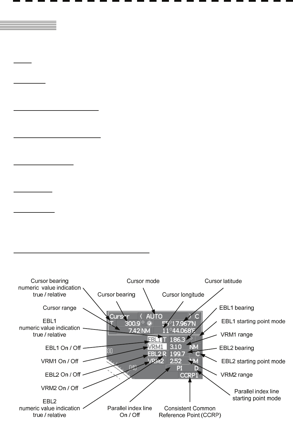
4.1 USE OF NAVIGATION TOOLS
The system is equipped with the navigation tools below.
Cursor
Specifies an arbitrary point, and measures the range and bearing from the own ship.
Range Rings
Displays concentric circles with own ship's position as the center at specified intervals, and the rings are
used as rough guides for range measurement.
Electronic Bearing Line (EBL1/2)
Displays a straight line for specifying an arbitrary bearing, and measures the bearing from the own ship.
The process unit is equipped with two electronic bearing lines.
Variable Range Marker (VRM1/2)
Displays a circle for specifying an arbitrary range, and measures the range from the own ship.
The process unit is equipped with two variable range markers.
Parallel Index Line (PI)
Displays straight lines at even intervals, and the lines are used as rough guides for complex measurement
or ship courses.
EBL Maneuver
Displays the course by steering the own ship, and it is used as a rough guide for ship maneuvering.
Man Overboard
Stores the latitude and longitude where the own ship was at the point of storing the markers, and shows
an anchor symbol on the radar display. When the own ship has moved, the system displays the range and
bearing to the position.
Use this tool when the ship is anchored or man overboard.
EBL/VRM/PI Operation with Cursor (Cursor AUTO)
Operates EBL, VRM, or PI on the radar display by using the cursor.
4-1

4
4.1 Use of Navigation Tools y
yyy
4.1.1 Using Cursor (Cursor)
Procedures 1 Move the cursor onto the PPI display by moving the trackball.
When the cursor is moved onto the PPI display, the arrow cursor turns into a cross cursor.
4.1.2 Using Range Rings [RR / HL]
Procedures 1 Press the [RR / HL] key.
The range ring display switches disappear and appear between display and non-display
each time the [RR / HL] key is pressed. The range ring interval is shown in the Range
Rings display on / off (upper left of the display ② on page 2-16).
The range between the target and own ship can be determined by visually measuring the
target's position that lies between two range rings.
For change of the brilliance of range rings, refer to Section 3.8.6.
4-2
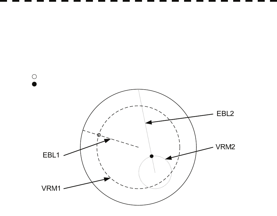
4.1.3 Using Electronic Bearing Line (EBL1/EBL2)
Electronic bearing lines (EBL) are indispensable to the measurement of bearings.
Operators must be familiar with the operation of EBL beforehand.
The system is equipped with two EBL. The bearing and starting point of an EBL can be operated
separately from the other EBL.
An intersection marker is displayed at the intersection point of the EBL and VRM of the same number.
Intersection markers shown on EBL:
: EBL1, VRM1
: EBL2, VRM2
EBL Bearing Display
The bearing value of the current EBL1 or EBL2 on the PPI display is shown in the
EBL1/2 bearing (upper right of the display on page 2-3). The currently operable EBL1 or
EBL2 is highlighted in the EBL1/2 adjustment (upper right of the display ⑤/⑦ on page
2-19).
Starting Point of EBL
The starting point of the currently operating EBL can be switched from the center of the
radar display to any offset position . The offset position of the EBL starting point can be
fixed on the radar display or at the latitude and longitude. (The setting of the navigator is
necessary for fixing the offset position at the latitude and longitude.)
4-3
4
4.1 Use of Navigation Tools y
yyy
[I] Operating EBL (EBL)
To operate EBL
Procedures 1 Press the [EBL1] or [EBL2] key.
The EBL adjustment (upper right of the display ⑤/⑦ on page 2-19) will be highlighted,
and the selected EBL becomes operable.
2 Turn the [EBL] dial.
To turn the [EBL] dial to the right, turn the EBL control clockwise, to turn the [EBL] dial
to the left, turn the EBL control counterclockwise.
Cancellation 1 Press the [EBL1] or [EBL2] key again.
The selected EBL display will disappear.
[II] Moving the Starting Point of EBL
The system provides three types of EBL starting points. Select one of them in accordance with
purpose.
:The EBL starting point is defined as the own ship's position.
C :The EBL starting point is moved and fixed on the radar display.
D :The EBL starting point is moved and fixed at the latitude and longitude.
(The navigator needs to be connected.)
To move the starting point of EBL
Procedures 1 Make EBL1 or EBL2 operable.
2 Press the [EBL] dial to set C or D for the EBL1 / EBL2 starting
point mode switching (upper right of the display ⑪/⑫ on page 2-19).
The selected EBL starting point mode is switched as shown below each time the dial is
pressed.
⇒ C ⇒ D ⇒
3 Put the cursor on the EBL starting point is to be moved, and press the
[ENT] key.
The selected EBL starting point will be determined.
4-4
To return the EBL starting point to own ship's position
Procedures 1 Make EBL1 or EBL2 operable.
2 Press the [EBL] dial to set for the EBL1 / EBL2 starting point mode
switching (upper right of the display ⑪/⑫ on page 2-19).
The selected EBL starting point will be set as the own ship's position.
[III] Setting EBL Operation Mode
To set the numeric value display mode of EBL (EBL Bearing REF)
Determine whether to display EBL in true bearing mode or relative bearing mode.
Procedures 1 Put the cursor on the EBL1/2 numeric value indication true / relative
switching (upper right of the display ⑨/⑩ on page 2-19), and press the
[ENT] key.
The selected mode is switched as shown below each time the [ENT] key is pressed.
T ⇒ R ⇒ T
T :EBL bearing is displayed in true bearing mode.
R :EBL bearing is displayed in relative bearing mode.
To set a mode for fixing EBL display (EBL Bearing Fix)
When this function is set to Angle , an EBL is fixed to the preset bearing. For example, if a
true bearing of 020° is preset, the EBL is fixed to the true bearing 020° even when the own
ship turns.
When the function is set to Screen , the EBL is fixed on the radar display. In this case, the
EBL is always fixed to the same bearing on the display when the own ship turns.
Procedures 1 Press the [RADAR MENU] key twice.
2 Open the EBL/Cursor Setting menu by performing the following menu
operation.
5. Sub Menu
9. EBL/Cursor Setting
3 Press [1] or [2] key.
To set EBL1, press the [1] key, to set EBL2, press the [2] key
Angle :EBL bearing is fixed to the preset value.
Screen :EBL bearing is fixed on the radar display.
Note: Course data is necessary for turning on this function.
4-5
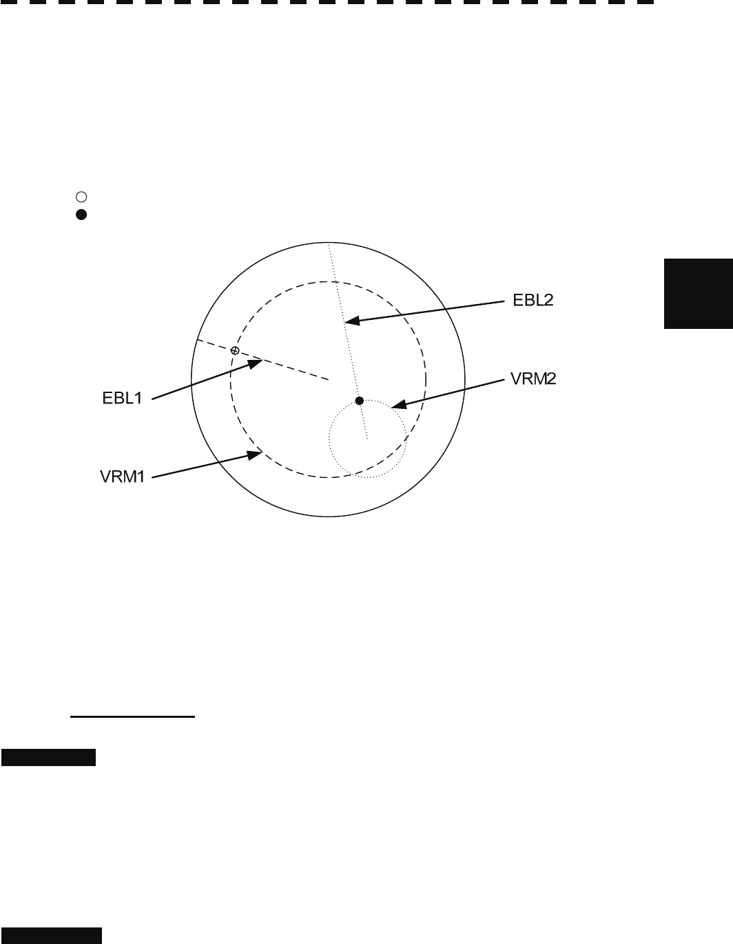
4
4.1 Use of Navigation Tools y
yyy
4.1.4 Using Variable Range Marker (VRM1 / VRM2)
Variable range markers (VRM) are indispensable to the measurement of ranges. Operators must be
familiar with the operation of VRM beforehand.
The system is equipped with two VRM. The VRM can be operated separately from each other.
An intersection marker is displayed at the intersection point of the VRM and EBL of the same number.
When the starting point of an EBL is offset, the center of the VRM is defined as the offset EBL starting
point.
Intersection markers shown on VRM:
: EBL1, VRM1
: EBL2, VRM2
VRM Operation
The range value of the current VRM1 or VRM2 on the PPI display is shown in the
VRM1/2 range (upper right of the display on page 2-3). The currently operable VRM1 or
VRM2 is highlighted in the VRM1/2 adjustment (upper right of the display ⑥/⑧ on
page 2-19).
To operate VRM
Procedures 1 Press the [VRM1] or [VRM2] key.
The VRM adjustment (upper right of the display ⑥/⑧ on page 2-19) will be highlighted,
and the selected VRM becomes operable.
2 Turn the [VRM] dial.
To turn the [VRM] dial to the right, the VRM control wide, to turn the [VRM] dial to the
left, the VRM control narrow.
Cancellation 1 Press the [VRM1] or [VRM2] key again.
The selected EBL display will disappear.
4-6

4.1.5 Using Parallel Index Lines (PI Menu)
Parallel index lines can be displayed.
[I] Operating Parallel Index Lines (PI)
Procedures 1 Press the [VRM] dial.
Parallel index lines and the PI Menu will appear.
To change the bearing of parallel index lines, turn the [EBL] dial, to change the line
interval, turn the [VRM] dial.
The bearing and interval of parallel index lines are displayed in the PI Menu.
2 Press the [VRM] dial again.
The parallel index lines will be fixed.
Note: Parallel index lines are operable only while the PI Menu is displayed. When the menu is closed,
the parallel index line display remains, but the settings of the bearing and interval cannot be
adjusted any more. To adjust the bearing and interval after closing the menu, press the [VRM]
dial twice to open the PI Menu.
Cancellation 1 Press the [VRM] dial again.
The parallel index line display will disappear.
4-7
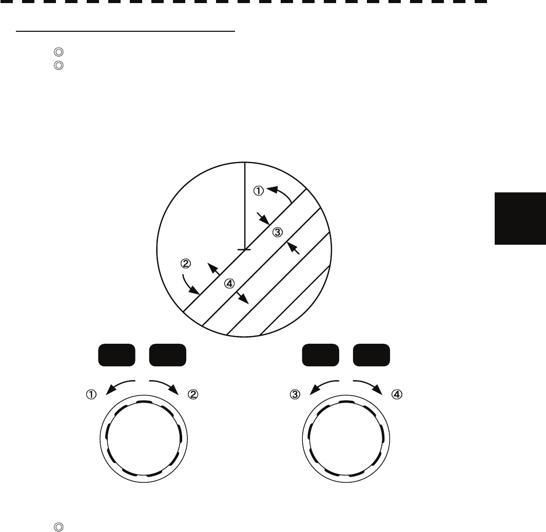
4
4.1 Use of Navigation Tools y
yyy
[II] Operation of Parallel Index Lines
Parallel index lines rotate in the same direction as you turn the [EBL] dial. ( ① , ② )
The intervals of parallel index lines narrow when you turn the [VRM] dial counterclockwise ( ③ ),
and widen when you turn the [VRM] dial clockwise ( ④ ).
HL
EBL1 EBL2 VRM1 VRM2
When the [VRM] dial is pressed, the PI Menu closes and the parallel index lines are fixed.
During the operation of parallel index lines, pressing the [EBL1] or [EBL2] key disables operation for
rotation directions. Pressing the [VRM1] or [VRM2] key disables operation for parallel index line
intervals.
4-8
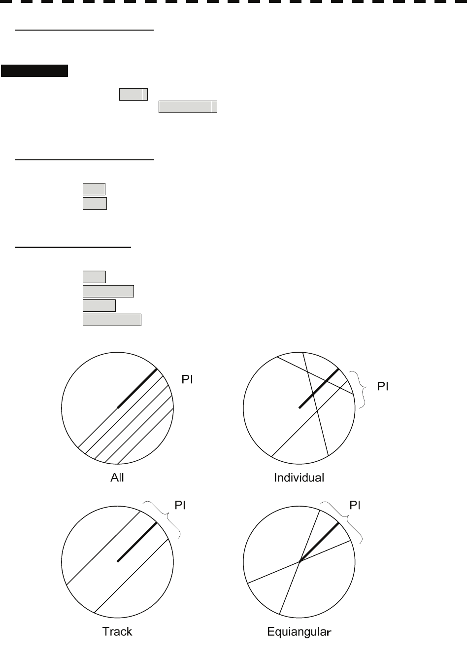
[III] Settings in PI Menu
The operation of parallel index lines can be set in the PI Menu.
Procedures 1 Open the PI Menu by performing the following menu operation.
Tool
1. PI Menu
[1] Display for All Lines
Sets the parallel index line display to on or off.
On :Parallel index lines are displayed.
Off :Parallel index lines are not displayed.
[2] Operation Mode
Sets an operation mode for parallel index lines.
All :All the parallel lines are operated at the same time.
Individual :The bearing of each line is operated individually.
Track :Equally spaced lateral lines are displayed on both sides.
Equiangular :Two lines intersecting at the center of a circle are displayed.
4-9
4
4.1 Use of Navigation Tools y
yyy
Operation if Individual is selected
A line perpendicular to the own ship and the intersection marker "----○" are displayed on an
operable line.
Turning the [EBL] dial changes the direction.
Pressing the [VRM] dial changes the range, end point 1, or end point 2 to be operated.
An operable point is displayed with " " and can be operated by turning the [VRM] dial.
If Sequential is selected for [3] Control, the parallel index lines of the next number can be
displayed by pressing the [EBL] dial.
To close the menu, press [0] key.
Operation if Equiangular is selected
Select a group of lines to be operated according to the setting of [3] Control.
Pressing the [EBL] dial switches between the direction change mode and elevation-angle change
mode. Turning the [EBL] dial changes the direction or elevation angle.
[3] Control
Determines whether to operate all the lines at the same time. The setting items are determined by the
setting of [2] Operation Mode.
If All is selected
The setting cannot be changed.
All :All the lines are operated at the same time.
If Individual is selected
Determine whether to set consecutive lines or individual lines.
Sequential :Lines are operated sequentially.
Index Line1 to Line8 :A specified line is operated.
If Track or Equiangular is selected
Select a group of lines to be operated.
Group1 to Group4 :A specified group is operated.
[4] Floating
Moves the center point of parallel index lines.
Off :The starting point of parallel index lines is defined as the own ship's
position.
Screen Fix :The center of parallel index lines is moved and fixed on the radar display.
L/L Fix :The center of parallel index lines is moved and fixed at the latitude
and :longitude. (The navigator needs to be connected.)
[5] Heading Link
Determines whether to operate parallel index lines following the heading bearing.
On :Parallel index lines are operated following the heading bearing.
Off :Parallel index lines are not operated following the heading bearing.
4-10
[6] Next
Moves to the next page.
[1] Range Scale Link
Determines the operation of parallel index line intervals when the range is changed.
On :The intervals are fixed with the actual range (nm).
The appearance of parallel index line intervals changes when the range is
changed.
Off :The intervals are fixed with the display range.
The parallel index line intervals (nm) change when the range is changed.
[2] Reference Bearing
Sets a reference bearing for the numeric data display of parallel index lines. The setting items are
determined by the setting of [2] Operation Mode.
If All is selected
True :Displayed with true bearing (with North as reference).
HL :Displayed with the heading line as reference.
If Individual is selected
True :Displayed with true bearing (with North as reference).
HL :Displayed with the heading line as reference.
Index Line1 to Line8 :Displayed with a specified line as reference.
If Track is selected
True :Displayed with true bearing (with North as reference).
HL :Displayed with the heading line as reference.
Index Line1 to Line8 :Displayed with a specified line as reference.
Line1 , Line3 , Line5 , and Line7
correspond to Group1 , Group2 , Group3 , and
Group4 , respectively.
If Equiangular is selected
The setting cannot be changed.
[3] Operation Area
If All is selected for [2] Operation Mode, this function sets an area for displaying parallel index
lines.
One Side :Parallel index lines are displayed only on one side.
Both Sides :Parallel index lines are displayed on both sides.
4-11
4
4.1 Use of Navigation Tools y
yyy
[4] Display for Individual Line
Determines whether to turn on / off the parallel index line display of a selected number.
On :The line of the selected number is displayed.
Off :The line of the selected number is not displayed.
If All is selected for [2] Operation Mode, the line near the own ship is line1.
If Track or Equiangular is selected for [2] Operation Mode, Line1 , Line3 , Line5 ,
and Line7 correspond to Group1 , Group2 , Group3 , and Group4 , respectively.
4.1.6 Operating EBL Maneuver Function (EBL Maneuver Setting)
[I] Initial Setting (EBL Maneuver Setting)
Procedures 1 Open the EBL Maneuver Setting menu by performing the following
menu operation.
Tool
3. EBL Maneuver Setting
2 Set the following parameters.
Reach :Set the range from when the rudder is steered to when the ship beings
to turn.
Turn Mode :Select a turn mode.
Radius :Turning radius (nm)
Rate :Rate of turn (deg/min)
Turn Set :Select the setting for turning.
If Radius is selected :Turning radius (nm)
If Rate is selected :Rate of turn (deg/min)
For inputs to the numeric value input menu, refer to Section 3.3.4.
Note: A wrong initial setting affects the maneuver curve function explained below.
4-12
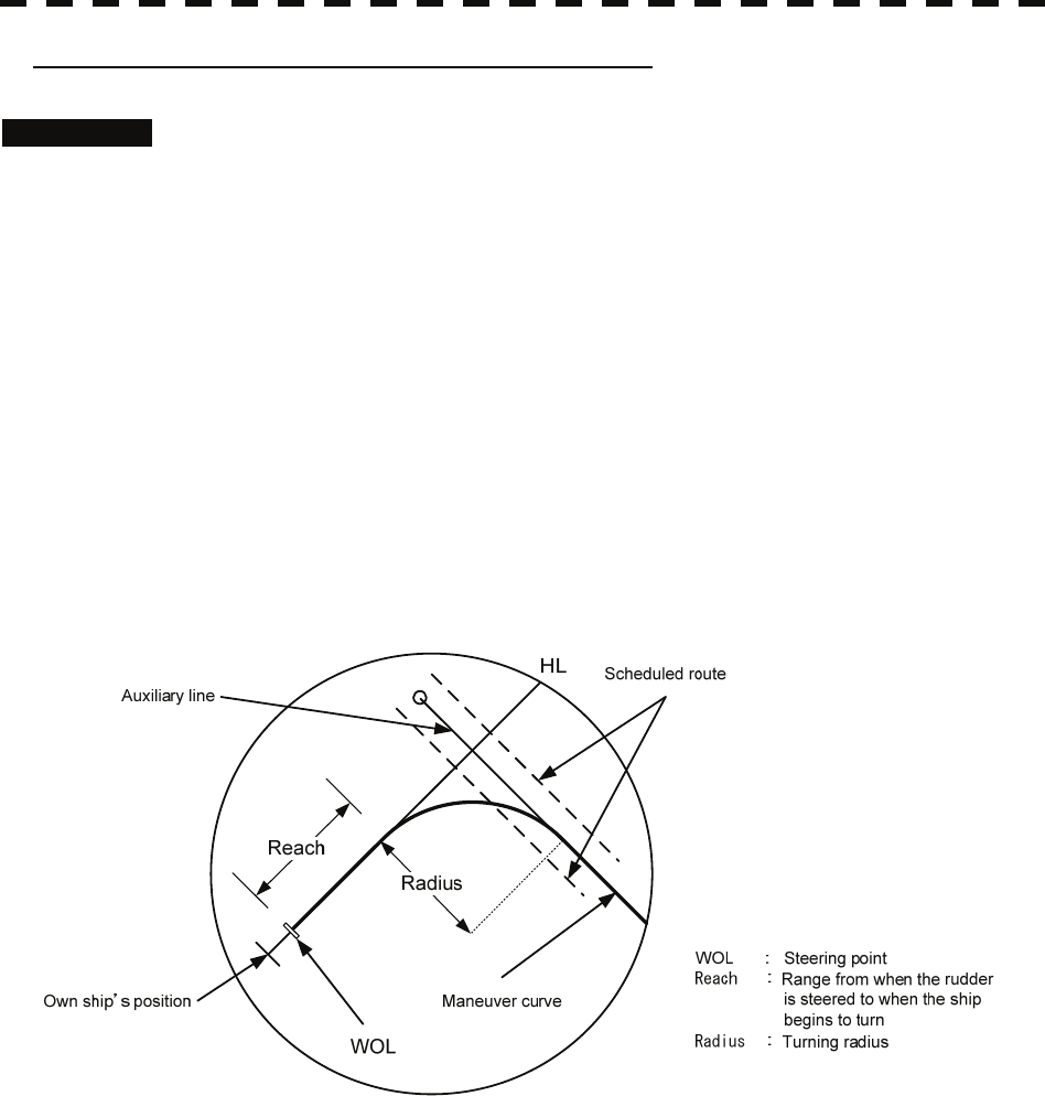
[II] Creation of Maneuver Curve (EBL Maneuver)
Procedures 1 Press the [1] key while the EBL Maneuver Setting menu is open.
The EBL maneuver function will be set to on or off.
A auxiliary line for maneuver curve creation, a maneuver curve, and a WOL will appear
on the radar display.
2 Put the cursor on the starting point of the auxiliary line, and set the
bearing of the auxiliary line by operating the [EBL] dial.
The bearing of the auxiliary line is the final bearing in which the own ship is to move.
The WOL position varies depending on the bearing of the auxiliary line.
If the WOL is behind the own ship's position, the line color of WOL will change.
3 Press the [ENT] key.
The setting will be determined. However, if the WOL is behind the own ship's position at
this point, pressing of the [ENT] key is rejected, and the setting is not determined.
4-13

4
4.1 Use of Navigation Tools y
yyy
4.1.7 Using MOB [MOB]
The marker (anchor symbol) function displays a dotted line from the marker input position to the own
ship's position, and indicates the range, bearing, and required time from the own ship's position to the
marker. (The navigator needs to be connected.)
For example, the function can be used for following purposes:
To confirm the drifting distance from where the ship was anchored.
To record a position of man overboard.
Procedures 1 Press the [MOB] key.
A marker will be displayed at the own ship's position on the radar display at the moment
when the [MOB] key is pressed. The own ship and the marker are connected with a dotted
line.
Even when the own ship moves, the marker is fixed at the latitude and longitude. Thus, if
a marker is put to an important position, the ship can return to the position regarding the
marker as a target.
Cancellation 1 Press the [MOB] key for 2 seconds.
The marker will disappear.
4.1.8 Operating EBL, VRM, and PI with Cursor
When the cursor mode is set to AUTO (upper right of the display on page 2-3), EBL,
VRM, and PI can be operated simply by using the trackball and the [ENT] key.
[I] Operating Electronic Bearing Line (EBL)
Procedures 1 Put the cursor on EBL1 or EBL2, and press the [ENT] key.
When the cursor is moved to it, EBL1 or EBL2 is shown at the upper right of the
cursor. The EBL becomes operable when the [ENT] key is pressed.
2 Move the cursor to the bearing to be set.
The EBL will move as the cursor moves.
3 Press the [ENT] key.
The EBL will be fixed.
4-14
[II] Operating Variable Range Marker (VRM)
Procedures 1 Put the cursor on VRM1 or VRM2, and press the [ENT] key.
When the cursor is moved to it, VRM1 or VRM2 is shown at the upper right of
the cursor. The VRM becomes operable when the [ENT] key is pressed.
2 Move the cursor to the range to be set.
The VRM will move as the cursor moves.
3 Press the [ENT] key.
The VRM will be fixed.
[III] Operating EBL and VRM Concurrently (EBL and VRM)
Procedures 1 Put the cursor on the intersection marker ( ○ or ● ), and press the
[ENT] key.
When the cursor is moved to it, EBL1 VRM1 or EBL2 VRM2 is shown at the
upper right of the cursor. The EBL and VRM become operable when the [ENT] key is
pressed.
2 Move the cursor to the bearing / range to be set.
The EBL and VRM will move as the cursor moves.
3 Press the [ENT] key.
The EBL and VRM will be fixed.
[IV] Operating Parallel Index Lines (PI)
To change the direction of parallel index lines
Procedures 1 Put the cursor on near the center of line, and press the [ENT] key.
When the cursor is moved there, it will turn into " " and PI will be displayed at the
upper right of the cursor. The parallel index lines become operable when the [ENT] key is
pressed.
2 Move the cursor to the direction to be set.
The parallel index lines will change the direction as the cursor moves.
3 Press the [ENT] key.
The parallel index lines will be fixed.
4-15