Japan Radio NKE2254 Marine Radar User Manual
Japan Radio Co Ltd. Marine Radar Users Manual
Contents
- 1. Users Manual 1
- 2. Users Manual 2
- 3. Users Manual 3
- 4. Users Manual 4
- 5. Users Manual
Users Manual 1

MARINE RADARMARINE RADAR
EQUIPMENTEQUIPMENT
INSTRUCTIONINSTRUCTION
MANUALMANUAL
JMA-5312-6/6HSJMA-5312-6/6HS
JMA-5322-7/9/6HSJMA-5322-7/9/6HS
JMA-5332-12JMA-5332-12
01ETM ISO 9001, ISO 14001 Certified
Printed in Japan
Marine Service Department
+81-3-3492-1305
+81-3-3779-1420
tmsc@jrc.co.jp
Telephone :
Facsimile :
e-mail :
AMSTERDAM Branch
Telephone :
Facsimile :
e-mail :
+31-20-658-0750
+31-20-658-0755
service@jrcams.nl
SEATTLE Branch
Telephone :
Facsimile :
e-mail :
+1-206-654-5644
+1-206-654-7030
service@jrcamerica.com
CODE No.7ZPRD0671
CODE No.7ZPRD0671
MAR. 2008 Edition 2 JRCMAR. 2008 Edition 2 JRC
Not use the asbestos
For further information,contact:
URL http://www.jrc.co.jp
◆◆◆PRECAUTIONS BEFORE OPERATION◆◆◆
■Cautions for high voltage
High voltages from hundreds volts to tens of thousands volts are to be applied to the electronic
equipment such radio and radar devices. You do not face any danger during normal operation,
but sufficient cares are required for maintenance, inspection and adjustment of their internal
components. (Maintenance, check-up and adjustment of the inside of the equipment are prohibited
except by maintenance specialists.)
High voltages of tens of thousands volts are so dangerous as to bring an instantaneous death from
electric shock, but even voltages of hundred volts may sometimes lead to a death from electric
shock. To prevent such an accident, make it a rule to turn off the power switch, discharge
capacitors with a wire surely earthed on an end make sure that internal parts are no longer charged
before you touch any parts inside these devices. At the time, wearing dry cotton gloves ensures
you further to prevent such danger. It is also a necessary caution to put one of your hands in the
pocket and not to use your both hands at the same time.
It is also important to select a stable foothold always to prevent additional injuries once you were
shocked by electricity. If you were injured from electric shock, disinfect the burn sufficiently
and get it taken care of promptly.
■What to do in case of electric shock
When finding a victim of electric shock, turn off the power source and earth the circuit
immediately.
If it is impossible to turn off the circuit, move the victim away promptly using insulators such as
dry wood plate and cloth without touching the victim directly.
In case of electric shock, breathing may stop suddenly if current flows to the respiration center in
the brain. If the shock is not so strong, artificial respiration may recover breathing. When
shocked by electricity, the victim will come to look very bad with weak pulse or without beating,
resulting in unconsciousness and rigidity. In this case, it is necessary to perform an emergency
measure immediately.
◆◆◆FIRST-AID TREATMENTS◆◆◆
☆First-aid treatments
As far as the victim of electric shock is not in dangerous condition, do not move him and practice
artificial respiration on him immediately. Once started, it should be continued rhythmically.
(1) Do not touch the victim confusedly as a result of the accident, but the rescuer may also get an
electric shock.
(2) Turn off the power source calmly and move the victim away quietly from the electric line.
(3) Call a physician or ambulance immediately or ask someone to call a doctor.
(4) Lay the victim on this back and loosen his necktie, clothes, belt, etc.
(5) a. Examine the victim’s pulse.
b. Examine his heartbeat bringing your ear close to his heart.
c. Examine his breathing bringing the back of your hand or your face close to his face.
d. Check the size of the pupils of his eyes.
(6) Open the victim’s mouth and take out artificial teeth, cigarette or chewing gum if any.
Keep his mouth open, stretch his tongue and insert a towel or the like in his mouth to prevent
the tongue from suffocating. (If it is hard to open his mouth due to set teeth, open it with a
screwdriver and insert a towel in this mouth.)
(7) Then, wipe his mouth so that foaming mucus does not accumulate inside.
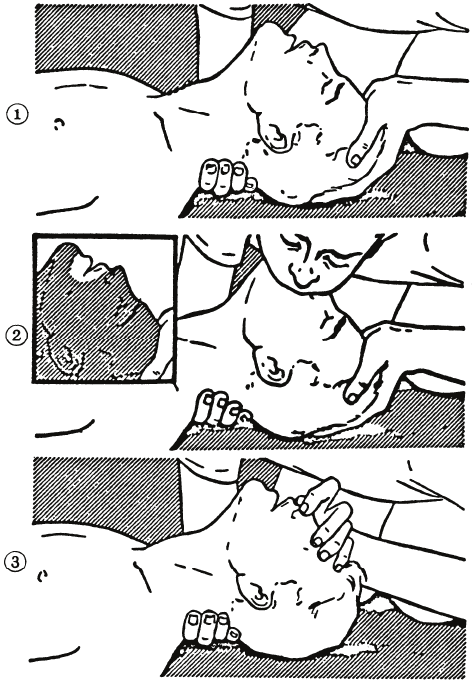
☆When pulse is beating but breathing has stopped
(Mouth-to-mouth respiration) Fig. 1
(1) Tilt the victim’s head back as far as this face looks back. (A pillow may be inserted his neck.)
(2) Push his jaw upward to open his throat wide (to spread his airway).
(3) Pinch the victim’s nostrils and take a deep breath, block his mouth completely with yours
and blow into his mouth strongly. Take a deep breath again and blow into his mouth.
Continue this 10 to 15 times a minutes (blocking his nostrils).
(4) Carefully watch that he has recovered his natural breathing and atop practicing artificial
respiration.
(5) If it is difficult to open the victim’s mouth, insert a rubber or vinyl tube into one of his
nostrils and blow into it blocking the other nostril and his mouth completely.
(6) When the victim recovers consciousness, he may try to stand up suddenly, but let him lie
calmly and serve him with a cup of hot coffee or tea and keep him warm and quiet. (Never
give him alcoholic drinks.)
Method of mouth-to-mouth respiration by raising head
(1) Raise the victim’s head. Support his
forehead with one of your hand and his
neck with the other hand. →1
When you tilt his head backward, the
victim, in most cases, opens his mouth to
the air. This makes mouth-to mouth
respiration easy.
(2) Cover his mouth as widely as possible with
yours and press your cheek against his nose
→2
or, pinch his nostrils with your fingers to
prevent air from leaking. →3
(3) Blow into his lungs. Continue blowing
into his mouth until his breast swells.
Blow into his mouth as quickly as possible
for the first 10 times.
Fig. 1 Mouth-to mouth respiration
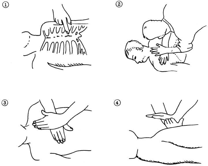
☆When both pulse and breathing have stopped
Perform the (Cardiac massage) Fig. 2 and (Mouth-to-mouth respiration) Fig. 1
When no pulse has come not to be felt, his pupils are open and no heartbeat is heard, cardiac arrest
is supposed to have occurred and artificial respiration must be performed.
(1) Place your both hands, one hand on the other, on the lower one third area of his breastbone
and compress his breast with your elbows applying your weight on his breast so that it is
dented about 2cm (Repeat compressing his breast 50 times or so a minutes). (Cardiac
massage)
(2) In case of one rescuer,
Repeat cardiac massages about 15 times and blow into his mouth 2 times quickly, and repeat
this combination.
In case of two rescuers,
One person repeats cardiac massages 15 times while the other person blow into his mouth
twice, and they shall repeat this combination. (Perform the cardiac massage and
mouth-to-mouth respiration)
(3) Examine his pupils and his pulse sometimes. When the both have returned to normal, stop
the artificial respiration, serve him with a cup of hot coffee or tea and keep him warm and
calm while watching him carefully. Commit the victim to a medical specialist depending
on his condition. (Never give him alcoholic drinks.) To let him recover from the mental
shock, it is necessary for persons concerned to understand his situations and the necessary
treatment.
Fig. 2 Cardiac massage
PREFACE
Thank you very much for purchasing the JRC marine radar equipment, JMA-5300MK2 series.
This equipment is a marine radar equipment designed to obtain safe operation of marine ships.
This equipment consists of a radar signal transmitter-receiver unit, a LCD display unit and a scanner unit as its
main units.
● Before operating the equipment, be sure to read this instruction manual carefully for correct operation.
● Maintain this instruction manual so that operators can refer to it at anytime.
Refer to this manual when any inconvenience or defect occurs.
- i -
●Before Operation●
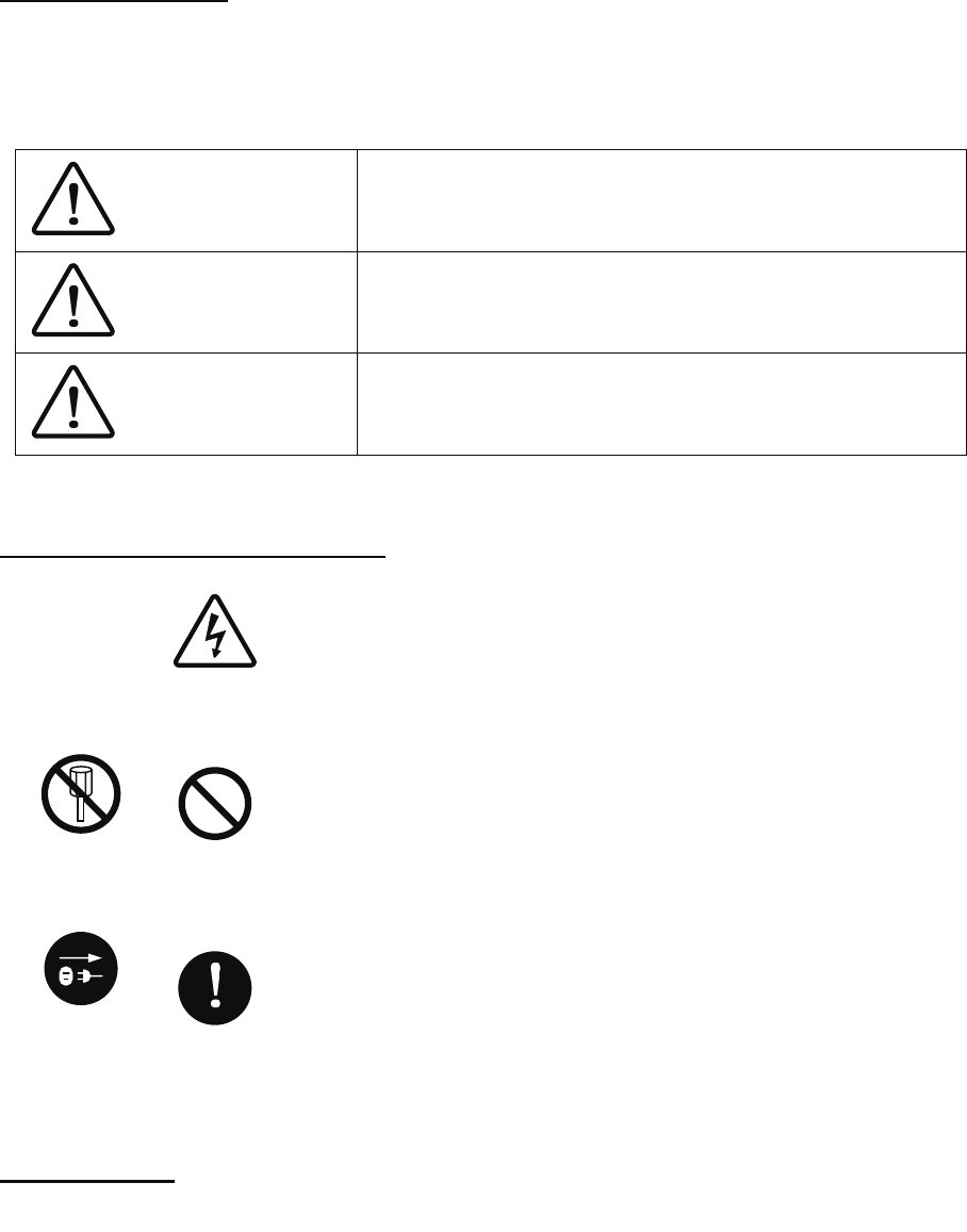
Pictorial Indication
Various pictorial indications are included in this manual and are shown on these equipment so that you can
operate them safety and correctly and prevent any danger to you and/or to other persons and any damage to
your property during operation. Such indications and their meanings are as follows.
Please understand them before you read this manual:
DANGER This indication is shown where incorrect equipment operation due to
negligence may cause death or serious injuries.
WARNING This indication is shown where any person is supposed to be in
danger of being killed or seriously injured if this indication is
neglected and these equipment are not operated correctly.
CAUTION This indication is shown where any person is supposed to be injured
or any property damage is supposed to occur if this indication is
neglected and these equipment are not operated correctly.
Examples of Pictorial Indication
Electric Shock
The U mark represents CAUTION (including DANGER and WARNING).
Detailed contents of CAUTION (“Electric Shock” in the example on the
left.) is shown in the mark.
Disassembling
Prohibited
Prohibited
The mark represents prohibition.
Detailed contents of the prohibited action (“Disassembling Prohibited” in the
example on the left.) is shown in the mark.
Instruction
The mark represents instruction.
Detailed contents of the instruction (“Disconnect the power plug “ in the
example on the left.) is shown in the mark.
Disconnect
the power
plug
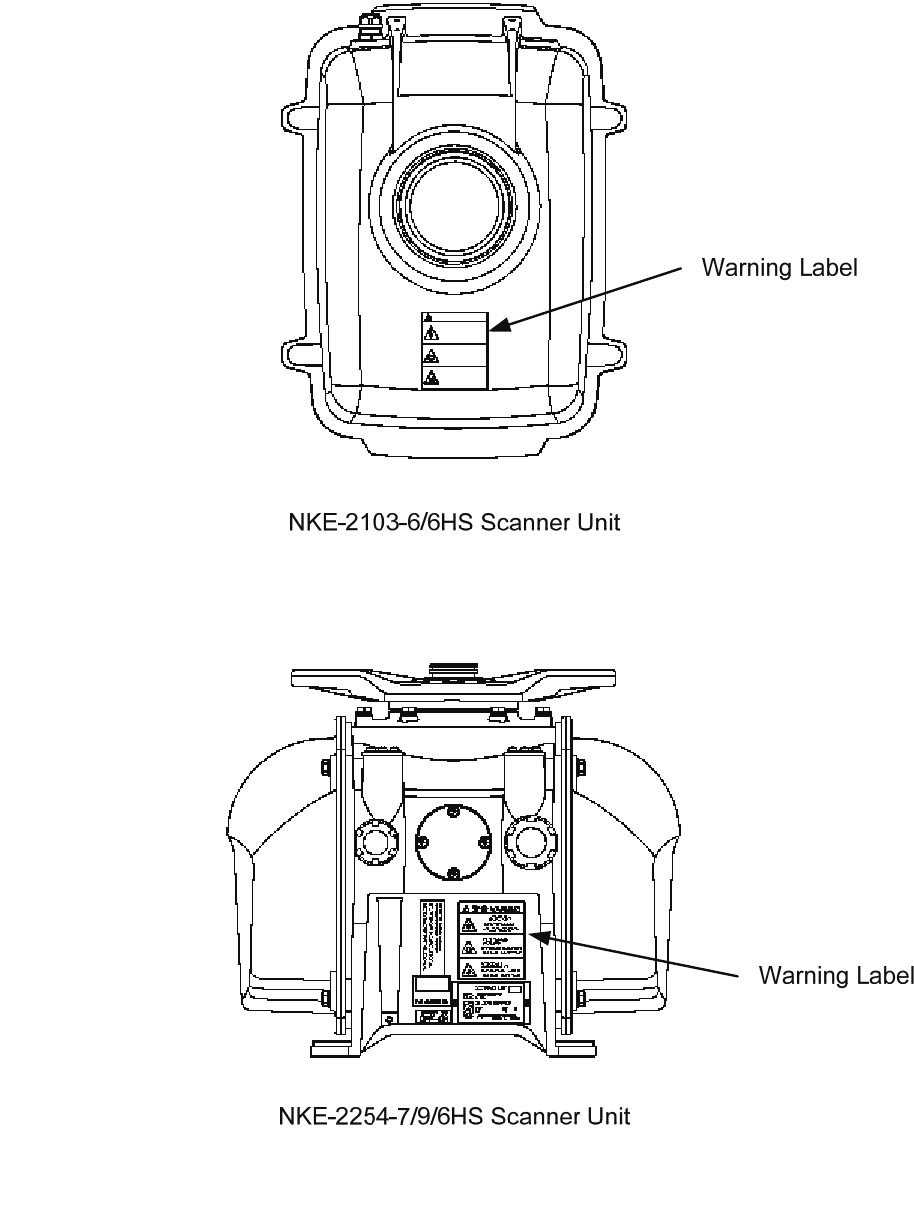
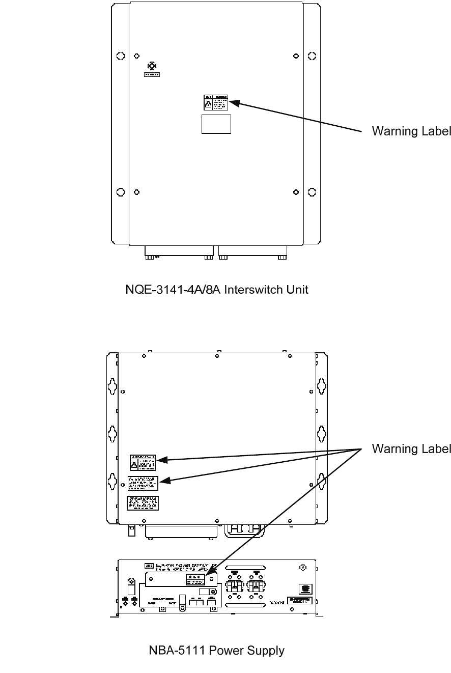
Warning Label
There is a warning label on the top cover of the equipment.
Do not try to remove, break or modify the label.
- ii -
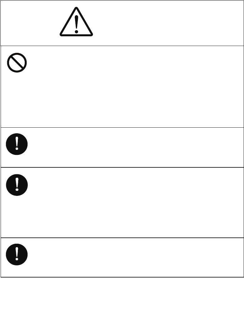
●PRECAUTIONS●
DANGER
Never conduct inspection or repair work of equipment
components.
Inspection or repair work by uncertified personnel may
result in fire hazard or electrocution.
For inspection and repair work of equipment
components, consult with our branch office, branch
shop, sales office, or our distributor in your district.
When conducting maintenance, make sure to turn the
main power off.
Failure to comply may result in electrocution.
Turn off the main power before cleaning the equipment.
Especially when a rectifier is used, make sure to turn it
off since voltage is still outputted from the rectifier even
after the indicator and the radar are turned off. Failure to
comply may result in equipment failure, or death or
serious injury due to electric shock.
When conducting maintenance work on the scanner,
make sure to turn its main power off.
Failure to comply may result in electrocution or injuries.
- iii -
DANGER
Make sure to turn off the scanner safety switch. Failure to
comply may result in injuries caused by physical contact
with the rotating scanner.
WARNING
Never directly touch the internal components of the
scanner or indicator. Direct contact with these
high-voltage components may cause electrocution. For
maintenance, inspection, or adjustment of equipment
components, consult with our branch office, branch
shop, sales office, or our distributor in your district.
To contact our sales department, branch offices, branch
shops, and sales offices:
Please refer to the "Office List" at the end of the
document.
Do not get close to the radiant section of the scanner. It is
a rotating part, and it may cause injuries if it suddenly
starts rotating and consequently hits the body. It is
recommended that the radiant section be installed at a
high place such as on the roof of the wheelhouse, on the
flying bridge, on the trestle, or on the radar mast so that
no one can get close to it. When any work must be done
on the scanner, make sure to turn the safety switch off.
- iv -
WARNING
Microwave radiation level:
Keep out from a distance closer than that specified below
for each type of scanner when it is transmitting. Being
within the specified distance from the center of the front
face of the scanner may cause microwave exposure
which could result in injuries (especially of the eyes).
NKE-2103/2254 (radiation levels: 10 W/m2): 0.6 m
NKE-1130 (radiation levels: 10 W/m2): 1.1 m
NKE-1130 (radiation levels: 100 W/m2): 25 cm
Make sure to install the scanner at a place higher than
human height.
Direct exposure to electromagnetic waves at close range
will have adverse effects on the human body.
Direct exposure to electromagnetic waves at close range
will have adverse effects on the human body. When it is
necessary to get close to the scanner for maintenance or
inspection purposes, make sure to turn the indicator
power switch to "OFF" or "STBY."
Direct exposure to electromagnetic waves at close range
will have adverse effects on the human body.
When conducting maintenance work, make sure to turn
off the power and unplug the power connector J1 of the
radar process unit so that the power supply to the
equipment is completely cut off.
Some equipment components can carry electrical current
even after the power switch is turned off, and conducting
maintenance work without unplugging the power
connector may result in electrocution, equipment failure,
or accidents.
- v -
Use the radar only as a navigation aid. The final
navigation decision must always be made by the operator
him/herself. Making the final navigation decision based
only on the radar display may cause accidents such as
collisions or running aground.
When cleaning the display screen, do not wipe it too
strongly with a dry cloth. Also, do not use gasoline or
thinner to clean the screen. Failure to comply will result
in damage to the screen surface.
WARNING
Do not change MBS Level/Area unless absolutely
necessary.
Incorrect adjustment will result in deletion of nearby
target images and thus collisions may occur resulting in
death or serious injuries.
When disposing of used lithium batteries, be sure to
insulate the batteries by attaching a piece of adhesive
tape on the ⊕ and { terminals. Failure to comply may
cause heat generation, explosion, or fire when the
batteries get shorted out.
CAUTION
- vi -
CAUTION
Use target tracking function only as a navigation aid. The
final navigation decision must always be made by the
operator him/herself. Making the final navigation decision
based only on tracking target information may cause
accidents.
Tracking target information such as vector, target
numerical data, and alarms may contain some errors.
Also, targets that are not detected by the radar cannot be
acquired or tracked.
Making the final navigation decision based only on the
radar display may cause accidents such as collisions or
When using the [AUTO SEA] function, never set the
suppression level too high canceling out all image noises
from the sea surface at close range.
Detection of not only echoes from waves but also targets
such as other ships or dangerous objects will become
inhibited.
When using the [AUTO SEA] function, make sure to
choose the most appropriate image noise suppression
level.
When using the [AUTO RAIN] function, never set the
suppression level too high canceling out all image noises
from the rain or snow at close range.
Detection of not only echoes from the rain or snow but
also targets such as other ships or dangerous objects will
become inhibited.
When using the [AUTO RAIN] function, make sure to
choose the most appropriate image noise suppression
level.
A malfunction may occur if the power in the ship is
instantaneously interrupted during operation of the radar.
In this case, the power should be turned on again.
- vii -
CAUTION
When setting a guard zone, make sure to properly adjust
gain, sea-surface reflection suppression level, and
rain/snow reflection suppression level so that the optimal
target images are always on the radar screen. The guard
zone alarm will not be activated for targets undetected by
the radar, and it may result in accidents such as
collisions.
The simulation function is used exclusively for deciding
whether or not target tracking is properly operating.
Therefore, never use this function unless you wish to
check target tracking operations.
Note especially that, if this function is used during actual
navigation, simulated targets are displayed and may
become confused with other actual targets. Therefore,
never use this function during actual navigation.
Optimal values have been set for VD LEVEL and
CONSTANT; therefore, never change their values unless
absolutely necessary. Failure to comply may result in
accidents that would lower target tracking performance.
Make sure to shut off the main power before replacing
parts. Failure to comply may result in electrocution or
equipment failure.
When replacing magnetrons, make sure to shut off the
main power and let the equipment stand for more than 5
minutes to discharge the high-voltage circuit. Failure to
comply may result in electrocution.
- viii -
CAUTION
Make sure to take off your watch when your hand must
get close to the magnetron.
Failure to comply may result in damage to the watch
since the magnetron is a strong magnet.
Make sure that two or more staff member work together
when replacing the LCD. If only one person attempts to
replace the LCD, he/she may drop it and become injured.
Do not directly touch the inverter circuit of the LCD
display with a bare hand since high voltage temporarily
remains in the circuit even after the main power is shut
off.
Failure to comply may result in electrocution.
Any adjustments must be made by specialized service
personnel.
Incorrect settings may result in unstable operation.
Do not make any adjustments during navigation. Failure
to comply may result in adverse effects on the radar
function which may lead to accidents or equipment
failure.
Any adjustments must be made by specialized service
personnel.
Failure to comply may result in accidents or equipment
failure.
Do not make any adjustments during navigation. Failure
to comply may result in adverse effects on the radar
function which may lead to accidents or equipment
failure.
- ix -
Do not change the quantization level settings unless
absolutely necessary. If set at an inappropriate value, the
target acquisition or target tracking function deteriorates,
and this may lead to accidents.
CAUTION
- x -
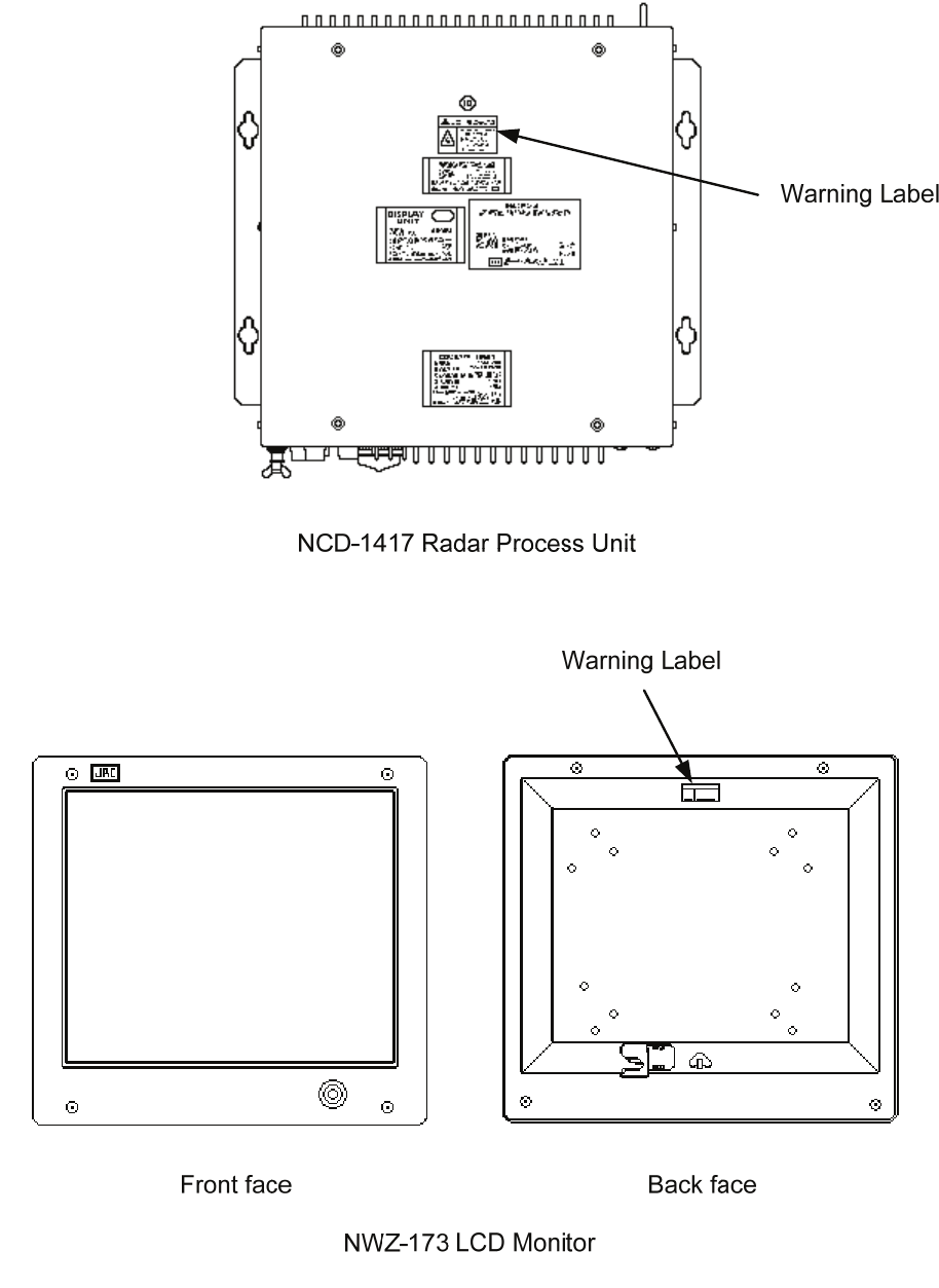
The Mounting Point of the Warning Label
- xi -
- xii -
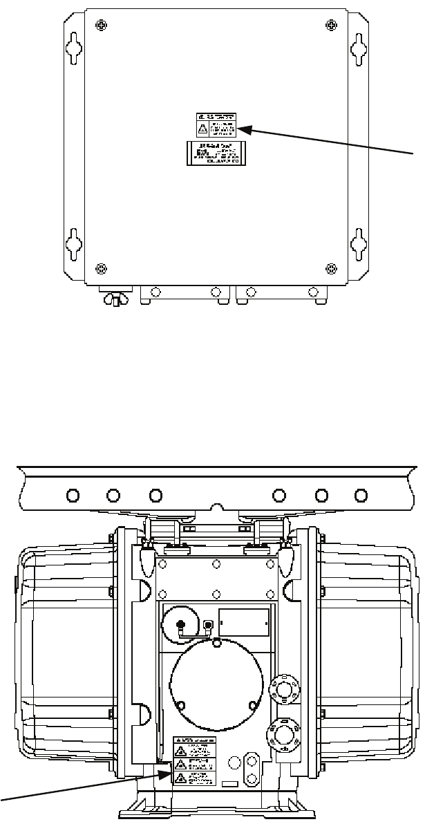
NKE-1130-12 Scanner Unit
NQE-3151A Junction Box
Warning
Label
Warning
Label
- xiii -
- xiv -
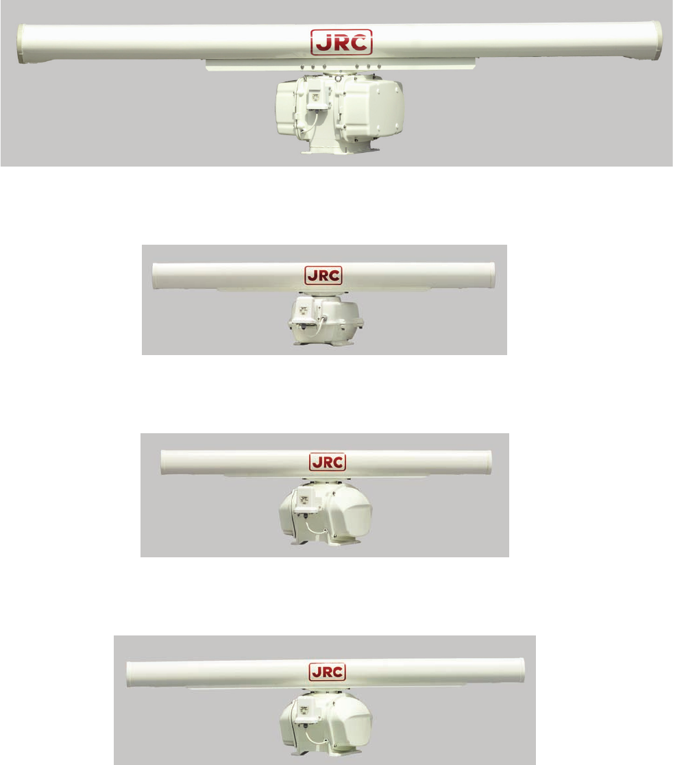
EQUIPMENT APPEARANCE
Scanner Unit Type NKE-1130 (12 feet)
Scanner Unit Type NKE-2103-6/6HS (6 feet)
Scanner Unit Type NKE-2254-6HS (6 feet)
Scanner Unit Type NKE-2254-7 (7 feet)
- xv -
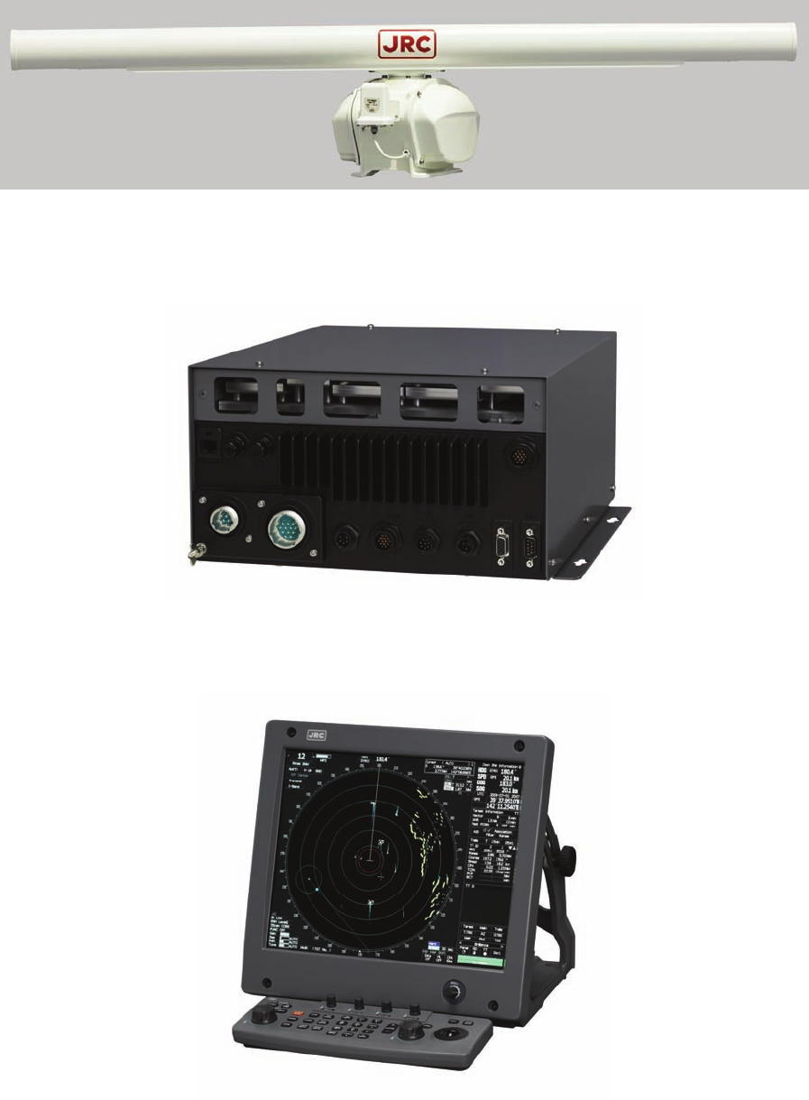
Scanner Unit Type NKE-2254-9 (9 feet)
NDC-1417 Processor Unit (Desktop Type)
NWZ-173 LCD Monitor Unit (Desktop Type)
NCE-5171 Operation Unit (Desktop Type)
NCD-4530 Display Unit (Desktop Type)
- xvi -

GLOSSARY
This section describes the main terms used for this equipment and general related maritime terms.
A
AZ
Acquisition/Activation zone
A zone set up by the operator in which the system should automatically
acquire radar targets and activate reported AIS targets when entering the
zone.
Activated target A target representing the automatic or manual activation of a sleeping
target for the display of additional information.
AIS Automatic Identification System
A system which enables ships and shore stations to obtain identifying
and navigation information about other ships at sea, using an automated
transponder.
Anti-clutter rain Rain/snow clutter suppression.
Anti-clutter sea Sea clutter suppression.
Associated target A target simultaneously representing a tracked target and a reported AIS
target having similar parameters (position, course, speed) which comply
with an association algorithm.
AZI AZImuth stabilization mode
B
BCR/BCT Bow Crossing Range and Bow Crossing Time
C
C up Course up
Own ship’s course is pointed to the top center of the radar display.
CCRP The Consistent Common Reference Point
A location on own ship, to which all horizontal measurements such as
target range, bearing, relative course, relative speed, CPA or TCPA are
referenced, typically the conning position of the bridge.
Clutter Unwanted reflections on a radar screen, from sea surface, rain or snow.
- xvii -
COG Course Over Ground
The direction of the ship's movement relative to the earth, measured on
board the ship, expressed in angular units from true north
CORREL CORRELation
CPA/TCPA The distance to the Closest Point of Approach and Time to the Closest
Point of Approach. Limits are set by the operator and are related to
own ship.
CTW Course Through Water
The direction of the ship's movement through the water
D
DRIFT The current velocity for manual correction or the current speed on the
horizontal axis of the 2-axis log is displayed.
E
EBL Electronic Bearing Line
An electronic bearing line originated from own ship’s position.
ETA Estimated Time of Arrival
G
Ground
stabilization A display mode in which speed and course information are referred to
the ground, using ground track input data.
H
HDG Heading
The horizontal direction that the bow of a ship is pointing at any instant,
expressed in angular units from a reference direction .
HL Heading line
A graphic line on a radar presentation drawn from the consistent
common reference point to the bearing scale to indicate the heading of
the ship
HSC Vessels which comply with the definition in SOLAS for high speed
craft
H up Head up
Own ship’s heading line is always pointed to the top center of the radar
display.
I
IMO International Maritime Organization
Interswitch Unit A device to switch over two or more radar display units and two or
more scanners.
- xviii -
IR radar Interference Rejecter
ISW InterSWitch L
Lost AIS target A target symbol representing the last valid position of an AIS target
before the reception of its data was lost, or its last dead-reckoned
position.
Lost tracked target One for which target information is no longer available due to poor, lost
or obscured signals.
LP Long Pulse M
MMSI Maritime Mobile Service Identity
MOB Man OverBoard
MON Performance monitor
MP Medium Pulse N
nm 1nm=1852m
N up North up
The north is always pointed to the top center of the radar display.
O
Own track Display function of own ship’s track
P
PI Parallel Index line
Past positions Equally time-spaced past position marks of a tracked or AIS target and
own ship.
POSN POSitioN
PRF Pulse Repetition Frequency
The number of radar pulses transmitted each second.
PROC PROCess
Radar signal processing function
R
Radar beacon A navigation aid which responds to the radar transmission by generating
a radar signal to identify its position and identity
- xix -
Radar cross-section Radar cross-section of a target determines the power density returned to
the radar for a particular power density incident on the target
Range Rings A set of concentric circles labeled by distance from CCRP.
Reference target A symbol indicating that the associated tracked stationary target is
used as a speed reference for the ground stabilization
Relative course The direction of motion of a target relative to own ship motion
Relative speed The speed of a target relative to own ship’s speed data
Relative vector A predicted movement of a target relative to own ship’s motion
RM Relative Motion
A display on which the position of own ship remains fixed, and all
targets move relative to own ship.
RM(R) Relative Motion. Relative Trails.
RM(T) Relative Motion. True Trails.
ROT Rate Of Turn
Change of heading per time unit.
Route A set of waypoints.
RR Range Rings S
SART Search And Rescue Transponder
Radar transponder capable of operating in the 9GHz band
Sea stabilization A display mode in which speed and course information are referred to
the sea.
Sea state Status of the sea condition due to the weather environment, expressed as
a sea state 0 for flat conditions with minimal wind, to sea state 8 for
very rough sea conditions.
SET The current direction for manual correction or the current speed on the
horizontal axis of the 2-axis log is displayed.
Sleeping AIS target A target indicating the presence and orientation of a vessel equipped
with AIS in a certain location.
- xx -
SOG Speed Over the Ground
The speed of the ship relative to the earth, measured on board of the
ship.
SP Short Pulse
STAB STABilization
STW Speed Through Water
The speed of the ship relative to the water surface.
T
TCPA Time to Closest Point of Approach to own ship
Test target Radar target of known characteristics used for test requirement
TM True Motion
A display across which own ship moves with its own true motion.
Trails Tracks displayed by the radar echoes of targets in the form of an
afterglow.
Trial maneuver A graphical simulation facility used to assist the operator to perform a
proposed maneuver for navigation and collision avoidance purposes.
True course The direction of motion relative to ground or to sea, of a target
expressed as an angular displacement from north
True speed The speed of a target relative to ground, or to sea
True vector A vector representing the predicted true motion of a target, showing
course and speed with reference to the ground or sea
TT Target Tracking.
A computer process of observing the sequential changes in the position
of a radar target in order to establish its motion. Such a target is a
Tracked Target.
TTG Time To Go.
Time to next waypoint.
TXRX Transceiver Unit U
UTC Universal Time Coordinated.
The international standard of time, kept by atomic clocks around the
world.
- xxi -
V
VRM Variable Range Marker
An adjustable range ring used to measure the distance to a target.
W
Waypoint A geographical location on a route indicating a event.
- xxii -

CONTENTS
PREFACE...............................................................................................................i
BEFORE OPERATION.......................................................................................... ii
PRECAUTIONS....................................................................................................iii
The Mounting Point of the Warning Label ........................................................xi
EQUIPMENT APPEARANCE..............................................................................xv
GLOSSARY.......................................................................................................xvii
1. GENERAL AND EQUIPMENT COMPOSITION
1.1 FUNCTIONS..............................................................................................1-1
1.1.1 FUNCTION OF THIS SYSTEM ............................................................1-1
1.2 FEATURES................................................................................................1-2
1.3 CONFIGURATION.....................................................................................1-4
1.4 EXTERIOR DRAWINGS............................................................................1-5
1.5 GENERAL SYSTEM DIAGRAMS............................................................1-15
2. NAMES AND FUNCTIONS OF CONTROL PANEL KEYS
AND FUNCTIONS OF SOFTWARE BUTTONS
2.1 NAMES OF DISPLAY................................................................................2-1
2.2 NAMES AND FUNCTIONS OF CONTROL PANEL KEYS ......................2-10
2.3 FUNCTIONS OF SOFTWARE BUTTONS...............................................2-15
3. BASIC OPERATION
3.1 OPERATION FLOW ..................................................................................3-1
3.1.1 POWER ON AND START THE SYSTEM..............................................3-2
3.1.2 OBSERVE AND ADJUST VIDEO.........................................................3-3
3.1.3 ACQUIRE AND MEASURE DATA........................................................3-3
3.1.4 DISPLAY AND MEASURE WITH REFERENCE TO CCRP..................3-3
3.1.5 END THE OPERATION AND STOP THE SYSTEM..............................3-4
3.2 OBSERVE AND ADJUST VIDEO..............................................................3-5
3.2.1 ADJUST MONITOR BRILLIANCE [BRILL]..........................................3-5
3.2.2 CHANGE OBSERVATION RANGE [RANGE + / - ] ..............................3-5
3.2.3 TUNE....................................................................................................3-6
3.2.4 ADJUST GAIN [GAIN / PL] ..................................................................3-7
3.2.5 SUPPRESS SEA CLUTTER [AUTO-SEA]...........................................3-8
3.2.6 SUPPRESS RAIN / SNOW CLUTTER [AUTO-RAIN].......................... 3-9
3.2.7 RESET ALARM BUZZER [ALARM ACK].......................................... 3-10
3.3 OPERATION PROCEDURES ................................................................. 3-11
3.3.1 MOVE CROSS CURSOR MARK BY TRACKBALL........................... 3-11
3.3.2 OPERATE SOFTWARE BUTTONS................................................... 3-12
3.3.3 BASIC MENU OPERATION............................................................... 3-13
3.3.4 OPERATION ON NUMERIC VALUE, LATITUDE / LONGITUDE AND
CHARACTER INPUT MENU.............................................................. 3-15
3.3.5 OVERVIEW OF MENU STRUCTURE................................................ 3-19
3.3.6 OPERATE MULTI-DIAL [MULTI] ....................................................... 3-19
3.4 GENERAL RADAR OPERATION ........................................................... 3-21
3.4.1 INTERFERENCE REJECTION (IR) ................................................... 3-21
3.4.2 SWITCH TRANSMITTER PULSE LENGTH [GAIN / PL] ................... 3-22
3.4.3 TARGET ENHANCE (ENH)................................................................ 3-23
3.4.4 USE VIDEO PROCESSING (PROC).................................................. 3-24
3.4.5 SWITCH AZIMUTH DISPLAY MODE [AZI MODE] ............................ 3-25
3.4.6 SWITCH TRUE / RELATIVE MOTION DISPLAY MODE [TM / RM].... 3-26
3.4.7 MOVE OWN SHIP’S DISPLAY POSITION [OFF CENT].................... 3-27
3.4.8 DISPLAY RADAR TRAILS [TRAILS]................................................. 3-28
3.4.9 ERASE PART OF RADAR TRAILS (TRAILS ERASE) ...................... 3-30
3.4.10 OPERATE RADAR TRAILS FILE (FILE OPERATIONS) ................... 3-31
3.4.11 ZOOM (X2)......................................................................................... 3-33
3.4.12 HIDE / DISPLAY RANGE RINGS (RR / HL) ....................................... 3-33
3.4.13 HIDE GRAPHICS INFORMATION ON RADAR DISPLAY
(DATA OFF) ...................................................................................... 3-34
3.4.14 SWITCH DAY / NIGHT MODE [DAY / NIGHT].................................... 3-34
3.4.15 ADJUST OPERATION PANEL BRILLIANCE [PANEL] ..................... 3-34
3.4.16 SET TRUE BEARING (GYRO SETTING) .......................................... 3-35
3.4.17 SET OWN SHIP SPEED..................................................................... 3-35
3.4.18 MAGNET COMPASS CORRECTION (MAG COMPASS SETTING).. 3-36
3.4.19 SET DRIFT CORRECTION (SET / DRIFT SETTING)......................... 3-37
3.4.20 GPS RECEIVER SETTING (GPS PROCESS SETTING)................... 3-38
3.4.21 DGPS RECEIVER SETTING (DGPS SETTING)................................ 3-42
3.4.22 SBAS RECEIVER SETTING (SBAS SETTING)................................. 3-43
3.4.23 DISPLAYING GPS RECEPTION STATUS (GPS STATUS)................ 3-46
3.4.24 SET RADAR ALARM (RADAR ALARM) ........................................... 3-47
3.5 USE OWN SHIP'S TRACK DATA............................................................ 3-49
3.5.1 DISPLAY OWN SHIP’S TRACK (DISPLAY OWN TRACK)................ 3-49
3.5.2 SAVE OWN SHIP'S TRACK DATA (OWN TRACK MEMORY)........... 3-50
3.5.3 CANCEL SAVING OF OWN SHIP’S TRACK DATA (OWN TRACK
MEMORY).......................................................................................... 3-50
3.5.4 CLEAR OWN SHIP’S TRACK DATA (CLEAR OWN TRACK) ........... 3-50
3.5.5 OPERATE OWN SHIP'S TRACK FILES (FILE OPERATIONS)......... 3-51
3.6 DISPLAY USER MAP.............................................................................. 3-54
3.6.1 CREATE USER MAP (MARK / LINE)................................................. 3-54
3.6.2 SET USER MAP DISPLAY (MARK DISPLAY SETTING)................... 3-57
3.6.3 EDIT USER MAP (EDIT USER MAP)................................................. 3-60
3.6.4 EDIT MARK / LINE LIST (MARK / LINE LIST) ................................... 3-66
3.6.5 CORRECT POSITION ON USER MAP (SHIFT USER MAP) ............. 3-72
3.6.6 OPERATE USER MAP FILE (FILE OPERATIONS) ........................... 3-73

3.6.7 SET AND DISPLAY GEODETIC SYSTEM (GEODETIC)....................3-77
3.7 USE ROUTE FUNCTION.........................................................................3-78
3.7.1 DISPLAY DESTINATION MARK (NMEA WAYPOINT DISPLAY) .......3-78
3.8 APPLIED OPERATIONS.........................................................................3-79
3.8.1 SET RADAR SIGNAL PROCESSING (PROCESS SETTING) ...........3-79
3.8.2 SET RADAR TRAILS (RADAR TRAILS SETTING) ...........................3-81
3.8.3 SET SCANNER UNIT (TXRX SETTING)............................................3-83
3.8.4 SET CURSOR (CURSOR SETTING) .................................................3-84
3.8.5 SET RADAR DISPLAY (DISPLAY SETTING) ....................................3-85
3.8.6 ADJUST SOUND VOLUME (BUZZER VOLUME)..............................3-87
3.8.7 SET USER KEYS [USER KEY 1 / 2]...................................................3-88
3.8.8 SET NAVIGATION DATA DISPLAY (MULTI WINDOW SETTING) .....3-90
3.9 USE FUNCTION KEY [FUNC].................................................................3-94
3.9.1 OPERATION PROCEDURES [FUNC] ...............................................3-94
3.9.2 FUNCTION SETTING MENU ITEMS (USER FUNCTION SETTING) .3-95
3.9.3 OVERVIEW OF FUNCTION OPERATIONS
(USER FUNCTION SETTING) ..........................................................3-96
3.9.4 OVERVIEW OF SAVED FUNCTION SETTING DATA........................3-99
3.10 USE USER SETTING ............................................................................3-100
3.10.1 SAVE OPERATING STATE (SAVE USER SETTING).......................3-100
3.10.2 LOAD OPERATING STATE (LOAD USER SETTING) .....................3-101
3.10.3 DELETE OPERATING STATE (DELETE USER SETTING) .............3-101
3.11 USING CARD ........................................................................................3-102
3.11.1 OPERATE FILE ON THE CARD (FILE MANAGER).........................3-102
3.12 DISPLAY SIMPLE CHART ....................................................................3-108
3.12.1 DISPLAY JRC COASTLINE ROM CARD [MAP]..............................3-108
3.12.2 DISPLAY ERC CARD [MAP]............................................................3-108
3.12.3 DISPLAY JRC CHART ON CF CARD (SEL JRC ROM CARD FILE)3-109
3.12.4 FILL CHARTS (FILL LAND AREA) .................................................. 3-110
3.12.5 SET JRC / ERC CHART DISPLAY (JRC / ERC SETTING)............... 3-111
3.12.6 DISPLAY C-MAP CARD [MAP]........................................................ 3-115
3.12.7 CORRECTING CHART POSITION (MAP DISPLAY SETTING) ....... 3-118
3.12.8 CHART PLOTTING BEARING MODE (MAP DRAW AZI MODE).....3-120
4. MEASUREMENT OF RANGE AND BEARING
4.1 USE OF NAVIGATION TOOLS..................................................................4-1
4.1.1 USING CURSOR (CURSOR)...............................................................4-2
4.1.2 USING RANGE RINGS [RR / HL]........................................................4-2
4.1.3 USING ELECTRONIC BEARING LINE (EBL1/EBL2).........................4-3
4.1.4 USING VARIABLE RANGE MARKER (VRM1 / VRM2) ......................4-6
4.1.5 USING PARALLEL INDEX LINES (PI MENU).....................................4-7
4.1.6 OPERATING EBL MANEUVER FUNCTION
(EBL MANEUVER SETTING) ..........................................................4-12
4.1.7 USING MOB [MOB] ...........................................................................4-14
4.1.8 OPERATING EBL, VRM, AND PI WITH CURSOR............................4-14
4.2 MEASUREMENT OF RANGE AND BEARING........................................4-17
4.2.1 MEASUREMENT WITH CURSOR POSITION (CURSOR)................4-17
4.2.2 MEASUREMENT WITH ELECTRONIC BEARING LINE AND
VARIABLE RANGE MARKER [EBL] [VRM]................................... 4-18
4.2.3 MEASUREMENT WITH TWO ARBITRARY POINTS........................ 4-19
5. OPERATION OF TARGET TRACKING AND AIS
5.1 PREPARATION......................................................................................... 5-2
5.1.1 COLLISION AVOIDANCE.................................................................... 5-3
5.1.2 DEFINITIONS OF SYMBOLS.............................................................. 5-6
5.1.3 RADAR DISPLAY................................................................................ 5-9
5.1.4 CURSOR MODES (CURSOR)........................................................... 5-11
5.1.5 SETTING COLLISION DECISION CRITERIA................................... 5-13
5.1.6 SETTING CPA RING.......................................................................... 5-13
5.1.7 SETTING VECTORS (VECTOR TIME).............................................. 5-14
5.1.8 SETTING THE GPS ANTENNA LOCATION ..................................... 5-15
5.2 TARGET TRACKING OPERATION ........................................................ 5-16
5.2.1 ACQUIRING TARGET [ACQ]............................................................ 5-16
5.2.2 CANCELING UNWANTED TRACKED TARGETS [TGT CNCL]....... 5-19
5.2.3 TRACKED TARGET DATA DISPLAY [TGT DATA]........................... 5-20
5.2.4 DISPLAYING TARGET ID NO. (TARGET NUMBER DISPLAY)........ 5-21
5.2.5 ADDING TRACKED TARGET ID NAME (NAME) ............................. 5-22
5.2.6 REFERENCE TARGET (REFERENCE) ............................................ 5-23
5.2.7 OPERATION TEST (TT TEST MENU)............................................... 5-25
5.3 AIS OPERATION..................................................................................... 5-30
5.3.1 RESTRICTIONS................................................................................. 5-30
5.3.2 SETTING AIS DISPLAY FUNCTION (AIS FUNCTION)..................... 5-30
5.3.3 ACTIVATE AIS TARGETS (ACTIVATE AIS)...................................... 5-31
5.3.4 DEACTIVATE AIS TARGETS (DEACTIVATE AIS)............................ 5-31
5.3.5 DISPLAYING AIS INFORMATION [TGT DATA]................................ 5-32
5.3.6 DISPLAYING TARGET ID NO. (TARGET NUMBER DISPLAY)........ 5-35
5.3.7 SETTING AIS FILTER (AIS FILTER SETTING)................................. 5-35
5.3.8 CONDITIONS FOR DECIDING AIS TARGET TO BE LOST............. 5-38
5.3.9 SETTING CONDITIONS FOR AIS ALARM (AIS ALARM SETTING) 5-39
5.4 DECISION OF TARGETS AS IDENTICAL (ASSOCIATION) .................. 5-40
5.5 ALARM DISPLAY ................................................................................... 5-42
5.6 TRACK FUNCTION ................................................................................ 5-46
5.6.1 PAST POSITION (PAST POSN)........................................................ 5-46
5.6.2 TARGET SHIP'S TRACKS (TARGET TRACK)................................. 5-47
5.7 TRIAL MANEUVERING (TRIAL MANEUVER) ....................................... 5-56
6. TRUE AND FALSE ECHOES ON DISPLAY
6.1 RADAR WAVE WITH THE HORIZON ....................................................... 6-1
6.2 STRENGTH OF REFLECTION FROM THE TARGET............................... 6-3
6.3 SEA CLUTTER AND RAIN AND SNOW CLUTTER.................................. 6-5
6.4 FALSE ECHOES....................................................................................... 6-9
6.5 DISPLAY OF RADAR TRANSPONDER (SART) .................................... 6-12

7. SETTINGS FOR SYSTEM OPERATION
7.1 SETTINGS AT INSTALLATION .................................................................7-1
7.1.1 HOW TO OPEN THE SERVICEMAN MENU .......................................7-1
7.1.2 GYRO I/F SETTING .............................................................................7-2
7.1.3 TUNING (TUNE ADJUSTMENT) .........................................................7-4
7.1.4 BEARING ADJUSTMENT....................................................................7-5
7.1.5 RANGE ADJUSTMENT .......................................................................7-6
7.1.6 NAVIGATOR SETTING (DEVICE)........................................................7-6
7.1.7 SETTING OF TRUE BEARING VALUE...............................................7-7
7.1.8 ANTENNA HEIGHT SETTING (ANTENNA HEIGHT)..........................7-7
7.1.9 SETTING OF CCRP/ANTENNA/GPS ANTENNA POSITION
(CCRP SETTING)...............................................................................7-8
7.2 SETTINGS...............................................................................................7-10
7.2.1 COMMUNICATION PORT SETTING (COM PORT SETTING)..........7-10
7.2.2 SECTOR BLANK SETTING (SECTOR BLANK)...............................7-14
7.2.3 TNI BLANK SETTING (TNI BLANK) .................................................7-15
7.2.4 SETTING OF BEARING PULSES FROM ANTENNA
(OUTPUT PULSE)............................................................................7-16
7.2.5 SLAVE MODE SETTING (MASTER/SLAVE).....................................7-17
7.2.6 LANGUAGE SETTING (LANGUAGE)...............................................7-18
7.2.7 DATE TIME SETTING........................................................................7-18
7.2.8 INPUT INSTALLATION INFORMATION ............................................7-19
7.2.9 SETTING THE ALARM SYSTEM ......................................................7-20
7.3 ADJUSTMENT ........................................................................................7-22
7.3.1 NOISE LEVEL ADJUSTMENT (NOISE LEVEL)................................7-22
7.3.2 ADJUSTMENT OF TARGET TRACKING FUNCTION (TT)...............7-24
7.3.3 MAIN BANG SUPPRESSION ADJUSTMENT (MBS) .......................7-27
7.3.4 ADJUSTMENT OF PERFORMANCE MONITOR (MON)...................7-28
7.4 MAINTENANCE MENU...........................................................................7-30
7.4.1 ANTENNA SAFETY SWITCH (SAFETY SWITCH)............................7-30
7.4.2 INITIALIZATION OF MEMORY AREA (AREA INITIAL) ....................7-31
7.4.3 SAVE OF INTERNAL MEMORY DATA (CARD2) ..............................7-32
7.4.4 CLEAR AND SAVE/RESTORATION OF ANTENNA OPERATION
TIME (TXRX TIME)...........................................................................7-33
7.4.5 UPDATE OF CHARACTER STRING DATA
(STRING DATA UPDATE) ................................................................7-35
8. MAINTEMANCE
8.1 ROUTINE MAINTENANCE .......................................................................8-1
8.2 MAINTENANCE ON EACH UNIT..............................................................8-2
8.2.1 SCANNER UNIT NKE-1130/2103/2254 ...............................................8-2
8.2.2 DISPLAY UNIT NCD-4530 ...................................................................8-5
8.3 PERFORMANCE CHECK....................................................................8-6
8.3.1 CHECK PERFORMANCE ON TEST MENU........................................8-7
8.4 REPLACEMENT OF MAJOR PARTS .....................................................8-11
8.4.1 PARTS REQUIRED FOR PERIODIC REPLACEMENT.....................8-12
8.4.2 REPLACEMENT OF MAGNETRON..................................................8-12
8.4.3 REPLACEMENT OF MOTOR............................................................ 8-19
8.4.4 REPLACEMENT OF LCD MONITOR................................................ 8-25
8.4.5 REPLACEMENT OF BACKUP BATTERY ........................................ 8-26
9. TROUBLESHOOTING AND AFTER-SALES SERVICE
9.1 FAULT FINDING........................................................................................ 9-1
9.1.1 LIST OF ALARMS AND OTHER INDICATIONS ................................. 9-1
9.1.2 OPERATION CHECKING .................................................................... 9-5
9.1.3 FUSE CHECKING................................................................................ 9-5
9.2 TROUBLE SHOOTING ............................................................................. 9-6
9.3 AFTER-SALES SERVICE....................................................................... 9-11
9.3.1 KEEPING PERIOD OF MAINTENANCE PARTS .............................. 9-11
9.3.2 WHEN YOU REQUEST FOR REPAIR............................................... 9-11
9.3.3 RECOMMENDED MAINTENANCE................................................... 9-11
10. DISPOSAL
10.1 DISPOSAL OF THE UNIT ....................................................................... 10-1
10.2 DISPOSAL OF USED BATTERIES......................................................... 10-1
10.3 DISPOSAL OF USED MAGNETRON ..................................................... 10-1
10.4 ABOUT THE CHINA ROHS..................................................................... 10-2
11. SPECIFICATIONS
11.1 JMA-5312-6/6HS TYPE RADAR............................................................. 11-1
11.2 JMA-5322-7/9/6HS TYPE RADAR.......................................................... 11-2
11.3 JMA-5332-12 TYPE RADAR................................................................... 11-3
11.4 SCANNER (NKE-2103-6)........................................................................ 11-4
11.5 SCANNER (NKE-2254-7/9)..................................................................... 11-5
11.6 SCANNER (NKE-1130)........................................................................... 11-6
11.7 SCANNER (NKE-2103-6HS)................................................................... 11-7
11.8 SCANNER (NKE-2254-6HS)................................................................... 11-8
11.9 DISPLAY UNIT (NCD-4530).................................................................... 11-9
11.10 PROCESSOR UNIT (NDC-1417) .......................................................... 11-10
11.11 TARGET TRACKING UNIT (NCA-877WA) ........................................... 11-12
11.12 AIS UNIT (NQA-2103)........................................................................... 11-13
11.13 PLOTTER.............................................................................................. 11-14
11.14 OPERATION UNIT (NCE-5171) ............................................................ 11-15
11.15 PERFORMANCE MONITOR (NJU-84) ................................................. 11-16
11.16 PERFORMANCE MONITOR (NJU-85) ................................................. 11-16
11.17 AVAILABLE INPUT SIGNAL................................................................. 11-17
11.18 AVAILABLE OUTPUT SIGNAL............................................................. 11-18
11.19 STANDARD CONFIGURATION............................................................ 11-18
11.20 EQUIPMENT DISTANCE BETWEEN OTHER INSTRUMENTS............ 11-19

APPENDIX
INTERSWITCH (OPTION) NQE-3141 INSTRUCTION MANUAL
HOW TO INSERT AND REMOVE A CARD
FIG.1 BLOCK DIAGRAM OF RADAR, TYPE JMA-5312-6/6HS/JMA-5322-7/9/6HS
FIG.2 BLOCK DIAGRAM OF RADAR, TYPE JMA-5332-12
FIG.3 TERMINAL BOARD CONNECTION DIAGRAM, TYPE JMA-5312-6/6HS
FIG.4 TERMINAL BOARD CONNECTION DIAGRAM, TYPE JMA-5322-7/9/6HS
FIG.5 TERMINAL BOARD CONNECTION DIAGRAM, TYPE JMA5332-12
FIG.6 TERMINAL BOARD CONNECTION DIAGRAM OF RADAR AND
INTERSWITCH UNIT, TYPE NQE-3141-4A
FIG.7 POWER SYSTEM DIAGRAM, TYPE JMA-5312-6/6HS,JMA-5322-7/9/6HS
FIG.8 POWER SYSTEM DIAGRAM, TYPE JMA-5332-12
FIG.9 INTERCONNECTION DIAGRAM OF RADAR PROCESS UNIT,
TYPE NCD-1417
FIG.10 INTERCONNECTION DIAGRAM OF INTERFACE UNIT, TYPE NQA-2123
FIG.11 INTERCONNECTION DIAGRAM OF OPERATION UNIT, TYPE NCE-5171
FIG.12 INTERCONNECTION DIAGRAM OF JUNCTION BOX, TYPE NQE-3151A
FIG.13 INTERCONNECTION DIAGRAM OF SCANNER UNIT, TYPE NKE-2103
FIG.14 INTERCONNECTION DIAGRAM OF SCANNER UNIT, TYPE NKE-2254
FIG.15 INTERCONNECTION DIAGRAM OF SCANNER UNIT, TYPE NKE-1130
(100/110/115V)
FIG.16 INTERCONNECTION DIAGRAM OF SCANNER UNIT, TYPE NKE-1130
(220/230/240V)
FIG.17 INTERCONNECTION DIAGRAM OF INTERSWITCH UNIT,
TYPE NQE-3141
FIG.18 OVER VIEW OF RADAR MENU

1 GENERAL AND EQUIPMENT COMPOSITION
2 NAME AND FUNCTION OF CONTROL PANEL KEYS AND
FUNCTION OF SOFTWARE BUTTONS
3 BASIC OPERATION
4 MEASUREMENT OF RANGE AND BEARING
5 OPERATION OF ARPA AND AIS
6 TRUE AND FALSE ECHOES ON DISPLAY
7 MAINTENANCE
8 COUNTERMEASURES FOR TROUBLE AND
ADJUSTMENT
9 AFTER-SALES SERVICE
10 DISPOSAL
11 SPECIFICATION
APPENDIX
1
2
3
4
5
6
7
8
9
10
11
APPENDIX
SECTION 1
GENERAL AND EQUIPMENT
COMPOSITION
1.1 FUNCTIONS .............................................................................................1-1
1.2 FEATURES...............................................................................................1-2
1.3 CONFIGURATION....................................................................................1-4
1.4 EXTERIOR DRAWINGS...........................................................................1-5
1.5 GENERAL SYSTEM DIAGRAMS ..........................................................1-16

1.1 FUNCTIONS
This equipment is a high-performance radar equipment consisting of a scanner unit, a transceiver unit and a
high resolution color LCD display unit.
1.1.1 Function of This System
The JMA-5300MK2 series is a color radar system designed to comply with the international standards of
the IMO.
The main functions include:
• gain adjustment
• sea clutter and rain / snow clutter suppression
• interference rejection
• bearing and range measurement using a cursor, fixed/variable range markers, and electronic bearing
line
• own track display
• colored own track display (7 colors) (option)
• NAV line and marker displays
• TM (True Motion) presentation
• self-diagnostic facilities
• radar performance monitoring (Performance Monitor, option)
• Target Tracking (TT) functions (manual / automatic target acquisition and automatic tracking, vector
and track displays and alarm displays) (option)
• simple plotter functions:
marker and line display (up to 2000 items.)
marker and line display (up to 20000 items.)(option)
waypoint / route setting (option)
• 8-unit switchover (Inter switch) function (option)
Note: Performance monitor, ARPA/ATA Process Unit, AIS Process Unit and GYRO Interface Unit must be
fitted on ships compliant to IMO.
1-1

1.2 Features y
1
1.2 FEATURES
Realization of Large, Easy-to-see Screen with High Resolution
The 19-inch color LCD with high resolution of 1280 × 1024 pixels can display radar images of 250 mm or
more in diameter. Even short-range targets can also be displayed as high-resolution images.
Target Detection by Latest Signal Processing Technology
The system employs the latest digital signal processing technology to eliminate undesired clutter from the radar
video signals that are obtained from the receiver with a wide dynamic range, thus improving the target
detection.
Advanced Technology Based Target Tracking (TT) Functions (Option)
The target acquisition and tracking performance is enhanced by the use of the fastest DSP and tracking
algorithm. So stable operation in target tracking under clutter is ensured.
• Acquisition and tracking of 100 targets for High performance edition, 30 targets for Normal edition.
• Hazardous conditions are represented by shapes and colors of symbols as well as sounds.
• Trial maneuvering functions provided. (High performance edition)
• Tracks of up to 20 target ships can be stored with a maximum of 1,500 points for each of them, and
displayed distinguished by using 7 different colors.
Note: ARPA/ATA Process Unit must be fitted on ships compliant to IMO.
Overlay of Radar Images, Coastlines, and Own Ship's Track
As well as operator-created NAV lines, the data of coastlines, objects such as buoys, and own ship's tracks /
target tracks / AIS tracks, which is stored on the memory card can be superimpose-displayed with radar images
and radar trails in all display modes including the head-up mode.
Creation / display of marks and lines (up to 2000 items).
Use of the optional plotter function enables the own track display distinguished by using 7 different colors,
creation of marks and lines (up to 20000 items) and the settings of waypoints / courses.
Easy Operation with GUI
All the radar functions can be easily controlled by simply using the trackball and 2 switches to operate the
buttons shown on the radar display.
Improved Day / Night Mode
Five types of background colors are available in Day / Dusk / Night mode.
Each background color can be reproduced to be suited for the user’s operating environment by simple key
operation. The radar echoes and a variety of graphics can also be represented in different colors, ensuring
easy-to-see displays.
1-2

Self-diagnostic Program Incorporated
The Self-diagnostic program always monitors all the functions of the system. If any function deteriorates, an
alarm message will appear on the radar display and an alarm sounds at the same time. Even when the system is
operating, the functionality test can be carried out. (except on some functions)
Performance Monitor (Option)
The radar performance (transmitted output power and receiving sensitivity) can appear on the radar display.
Note: Performance monitor must be fitted on ships compliant to IMO.
Easy Interswitch Operation (Option)
If an interswitch unit (option) is connected, up to four JMA-5300MK2 radars can be switched over by
performing simple operation.
* An interswitch (NQE-3141) is needed separately.
Various Functions
• RADAR Trails
• TM (True Motion) display
• Head-up / North-up / Course-up display
• Own ship’s track display
• Automatic Acquisition / Activation function
1-3
1.3 Configuration y
1
1.3 CONFIGURATION
Specified of scanner, and categories of ship/craft for SOLAS V
Radar Model Antenna Type Transmitted
Output Power Band Rate of
Rotation Category
JMA-5312-6 6 ft slot antenna 10 kW X 27rpm CAT 2
JMA-5312-6HS 6 ft slot antenna 10 kW X 48rpm CAT 2H
JMA-5322-7 7 ft slot antenna 25 kW X 24rpm CAT 2
JMA-5322-9 9 ft slot antenna 25 kW X 24rpm CAT 2
JMA-5322-6HS 6 ft slot antenna 25 kW X 48rpm CAT 2H
JMA-5332-12 12 ft slot antenna 30 kW S 24rpm CAT 2
*The class of emission: P0N (All scanner types)
Radar Configuration and Ship’s Mains
Radar Model Scanner Unit Performance
Monitor (option) Display Unit Ship’s Mains
JMA-5312-6 NKE-2103-6 NJU-85 NCD-4530 24 VDC
JMA-5312-6HS NKE-2103-6HS NJU-85 NCD-4530 24 VDC
JMA-5322-7 NKE-2254-7 NJU-85 NCD-4530 24 VDC
JMA-5322-9 NKE-2254-9 NJU-85 NCD-4530 24 VDC
JMA-5322-6HS NKE-2254-6HS NJU-85 NCD-4530 24 VDC
NCD-4530 24 VDC
100/110/115VAC,1φ,50/60Hz
JMA-5332-12 NKE-1130 NJU-84 *NQE-3151A 220/230/240VAC,1φ,50/60Hz
* The NQE-3151A included in JMA-5332-12 is a connection unit to supply AC power for the motor to the
scanner unit.
Notes:
1. The JMA-5332-12 needs 24 VDC as the power supply of the radar process unit, and AC power for the
motor to drive the scanner unit.
2. The table above shows six types of power supplies available for the motor of JMA-5332-12.
3. An optional POWER SUPPLY NBA-5111 is necessary for using Ship's Mains
100/110/115/220/230/240 VAC,1φ,50/60Hz.
4. The DISPLAY UNIT NCD-4530 has a separate structure consisting of the following:
LCD MONITOR NWZ-173
CONTROL UNIT NCM-853
The control unit NCM-853 is consisting of the following
RADAR PROCESS UNIT NDC-1417
OPERATION UNIT NCE-5171
5. The ship with radar of IMO conformity must mount a Performance Monitor.
1-4

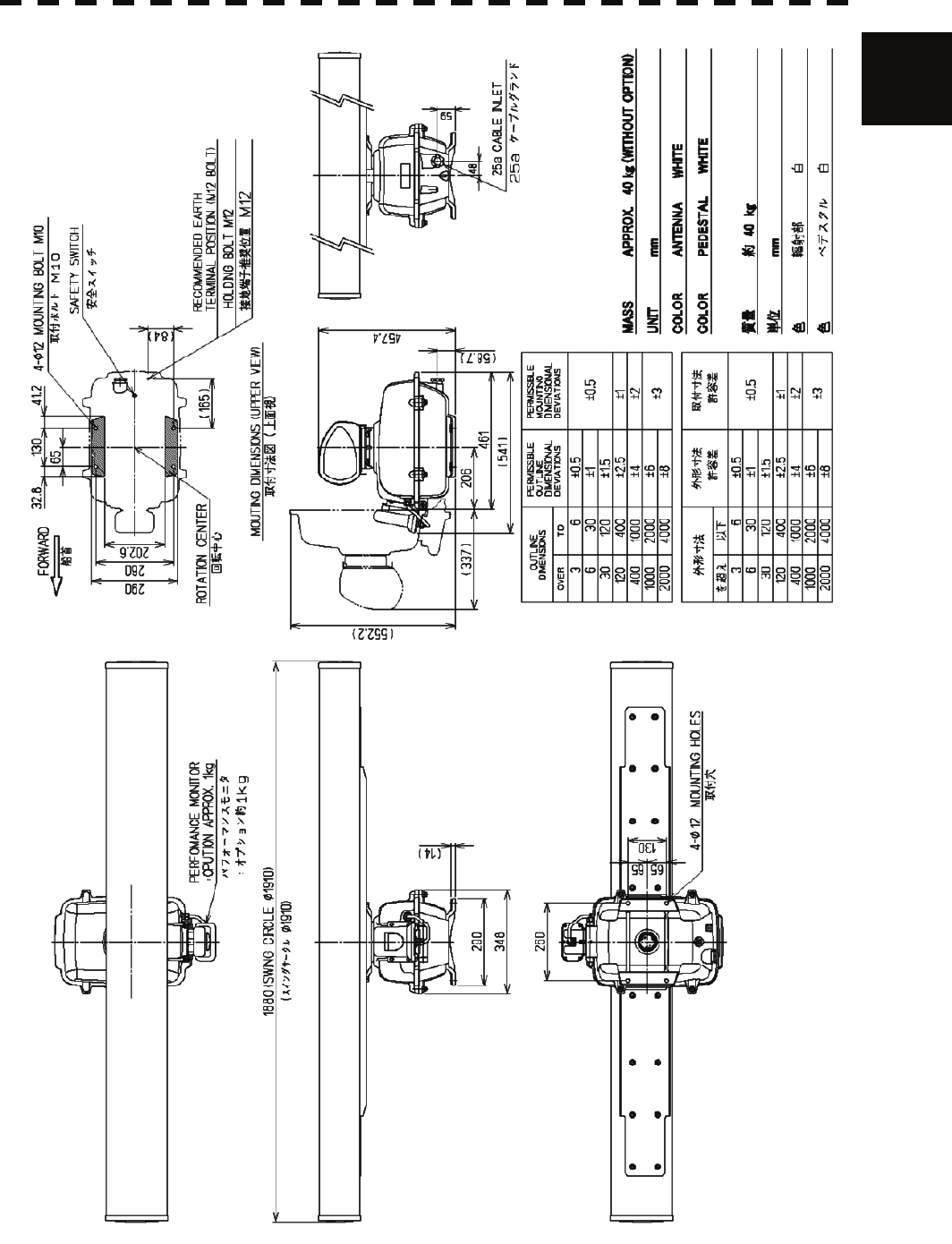
1.4 EXTERIOR DRAWINGS
Fig. 1.1 Exterior Drawing of Scanner Unit, Type NKE-2103-6 / 6HS
Fig. 1.2 Exterior Drawing of Scanner Unit, Type NKE-2254-7
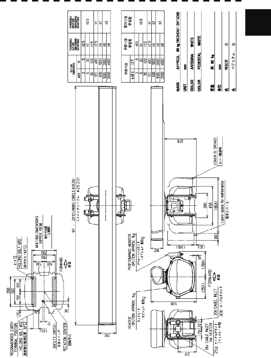
Fig. 1.3 Exterior Drawing of Scanner Unit, Type NKE-2254-9
Fig. 1.4 Exterior Drawing of Scanner Unit, Type NKE-2254-6HS
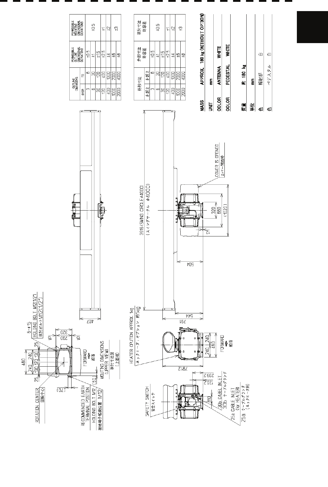
Fig. 1.5 Exterior Drawing of Scanner Unit, Type NKE-1130
Fig. 1.6 Exterior Drawing of Display Unit, Type NWZ-173
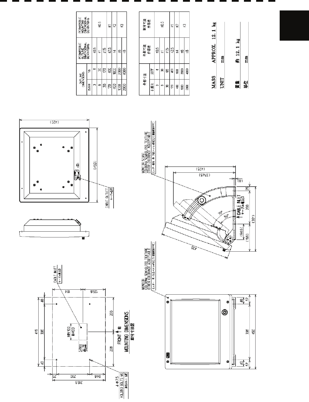
Fig. 1.7 Exterior Drawing of Display Unit, Type NWZ-173 with Stand MPBC42446 (option)
Fig. 1.8 Exterior Drawing of Processing Unit, Type NDC-1417
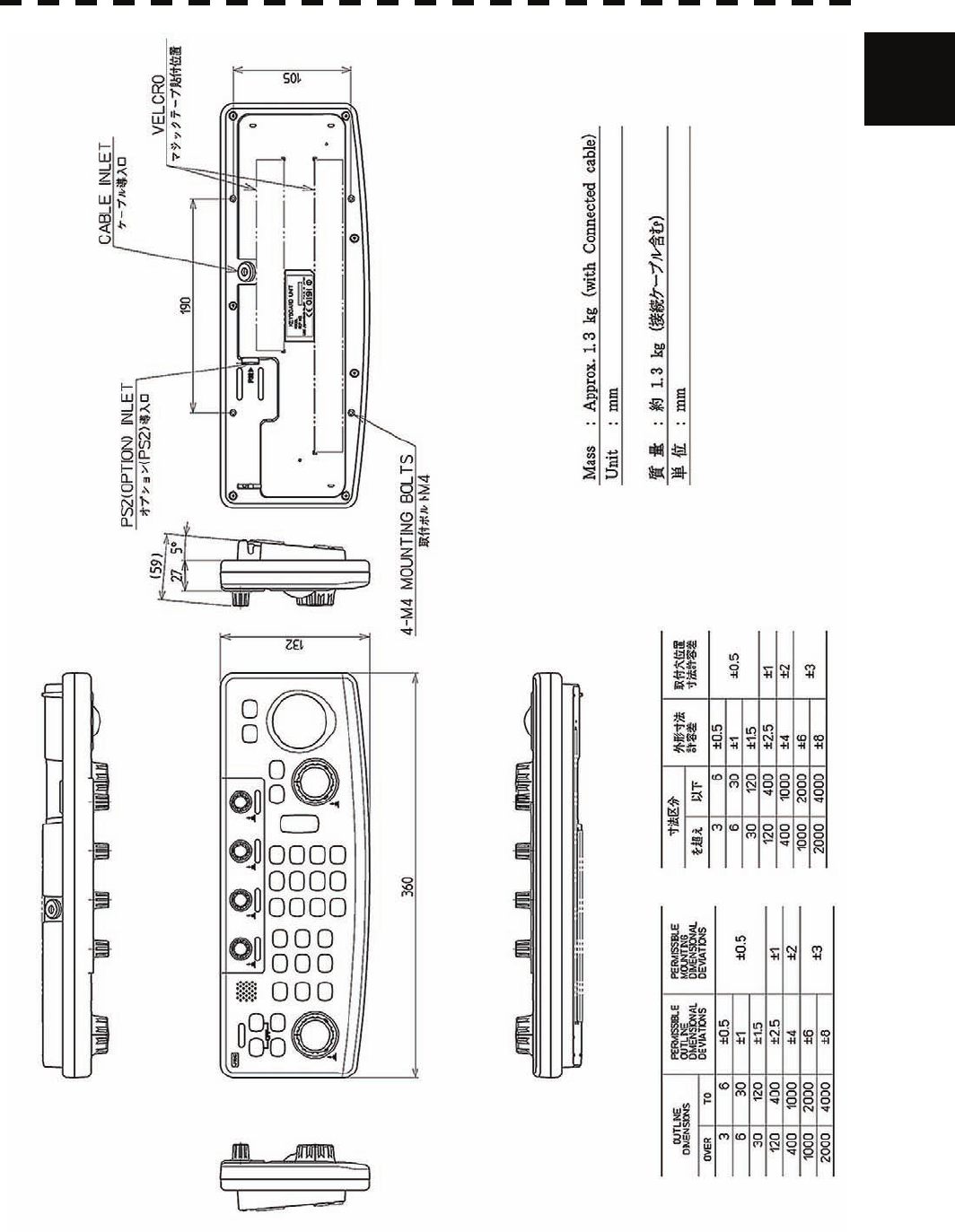
Fig. 1.9 Exterior Drawing of Operating Unit, Type NCE-5171
Fig. 1.10 Exterior Drawing of Connecting Unit, Type NQE-3151A
1-5
1.4 Exterior Drawings y
1
Fig. 1.1 Exterior Drawing of Scanner Unit, Type NKE-2103-6 / 6HS
1-6
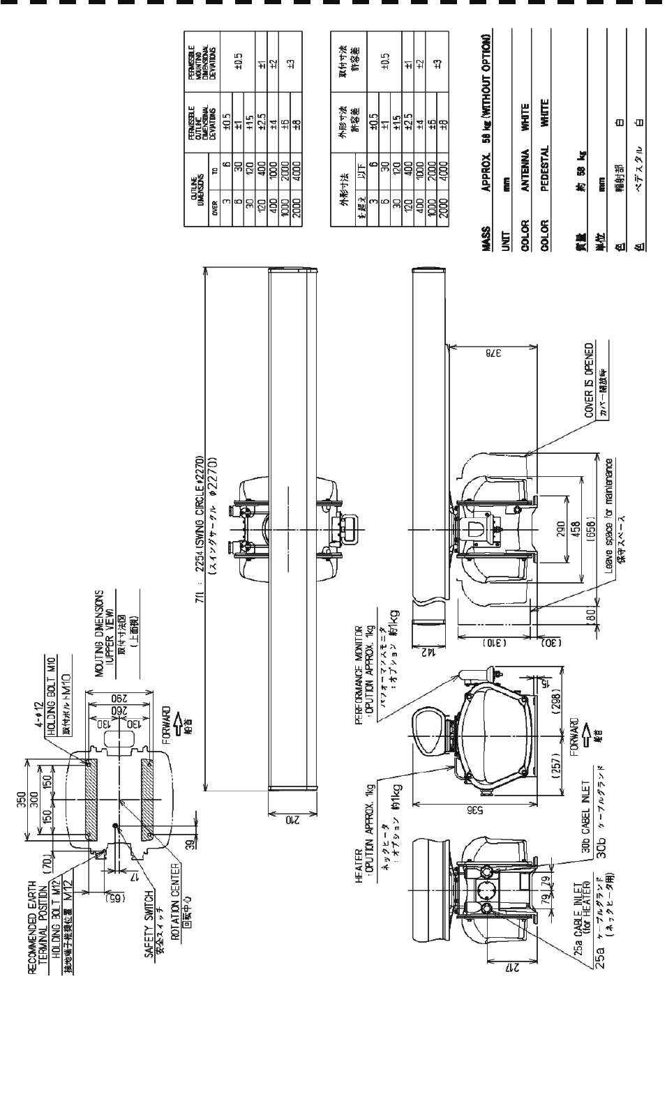
Fig. 1.2 Exterior Drawing of Scanner Unit, Type NKE-2254-7
1-7
1.4 Exterior Drawings y
1
Fig. 1.3 Exterior Drawing of Scanner Unit, Type NKE-2254-9
1-8
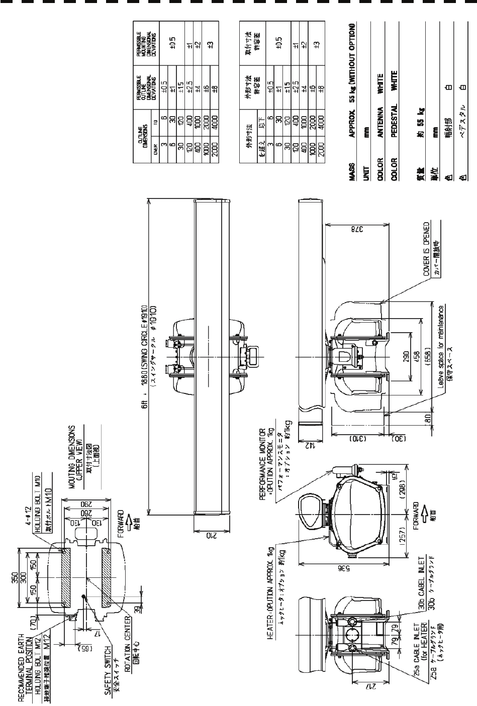
Fig. 1.4 Exterior Drawing of Scanner Unit, Type NKE-2254-6HS
1-9
1.4 Exterior Drawings y
1
Fig. 1.5 Exterior Drawing of Scanner Unit, Type NKE-1130
1-10
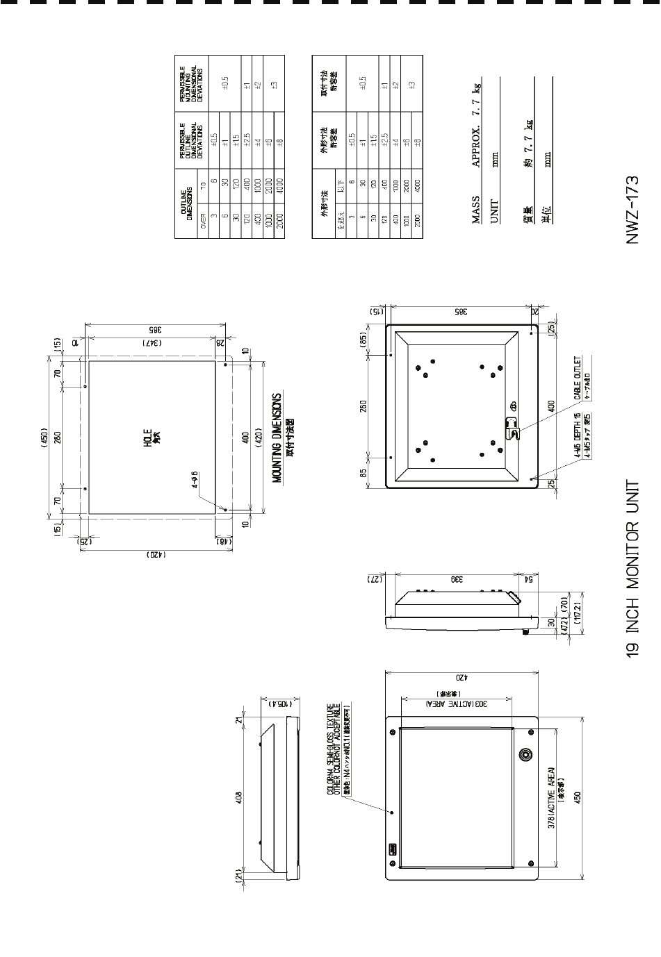
Fig. 1.6 Exterior Drawing of Display Unit, Type NWZ-173
1-11
1.4 Exterior Drawings y
1
Fig. 1.7 Exterior Drawing of Display Unit, Type NWZ-173 with Stand MPBC42446 (option)
1-12
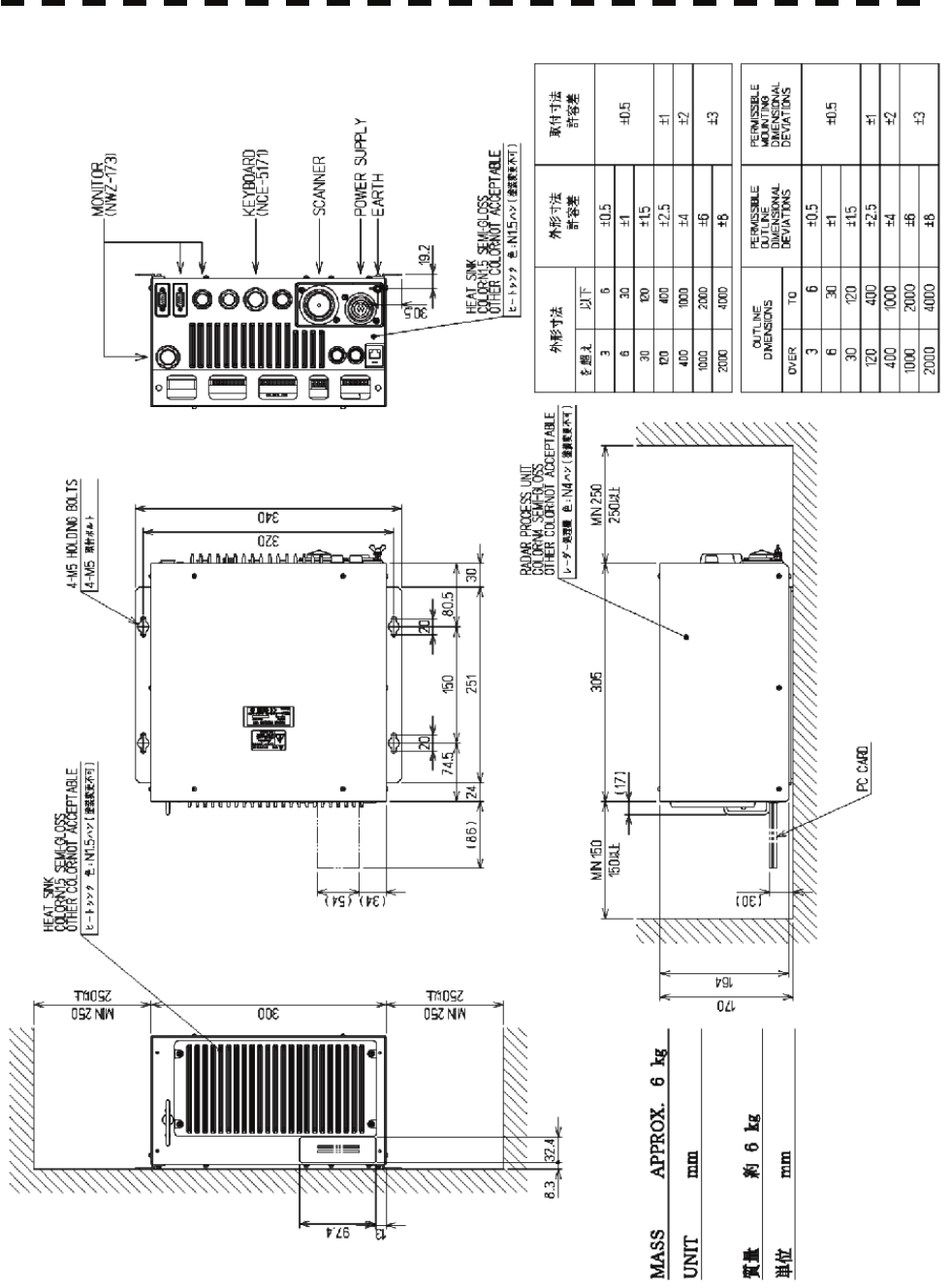
Fig. 1.8 Exterior Drawing of Radar Process Unit, Type NDC-1417
1-13
1.4 Exterior Drawings y
1
Fig. 1.9 Exterior Drawing of Operation Unit, Type NCE-5171
1-14
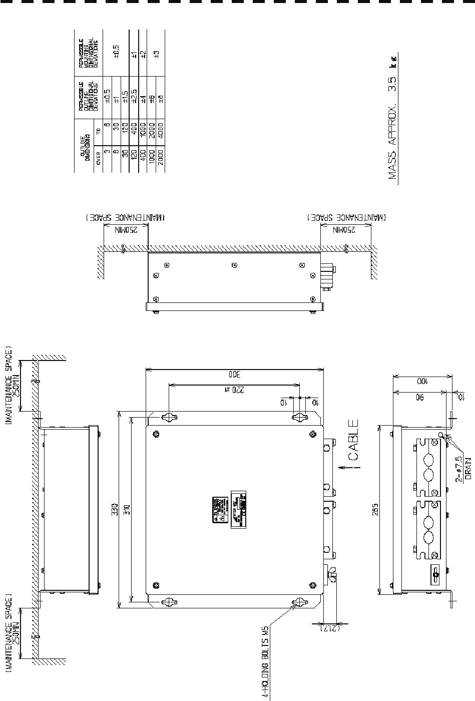
Fig. 1.10 Exterior Drawing of Junction Box, Type NQE-3151A
1-15

1.5 General System Diagrams y
1
1.5 GENERAL SYSTEM DIAGRAMS
Fig. 1.10 General System Diagram of Radar, Type JMA-5312-6 /6HS
Fig. 1.11 General System Diagram of Radar, Type JMA-5322-7 / 9 6HS
Fig. 1.12 General System Diagram of Radar, Type JMA-5332-12
1-16
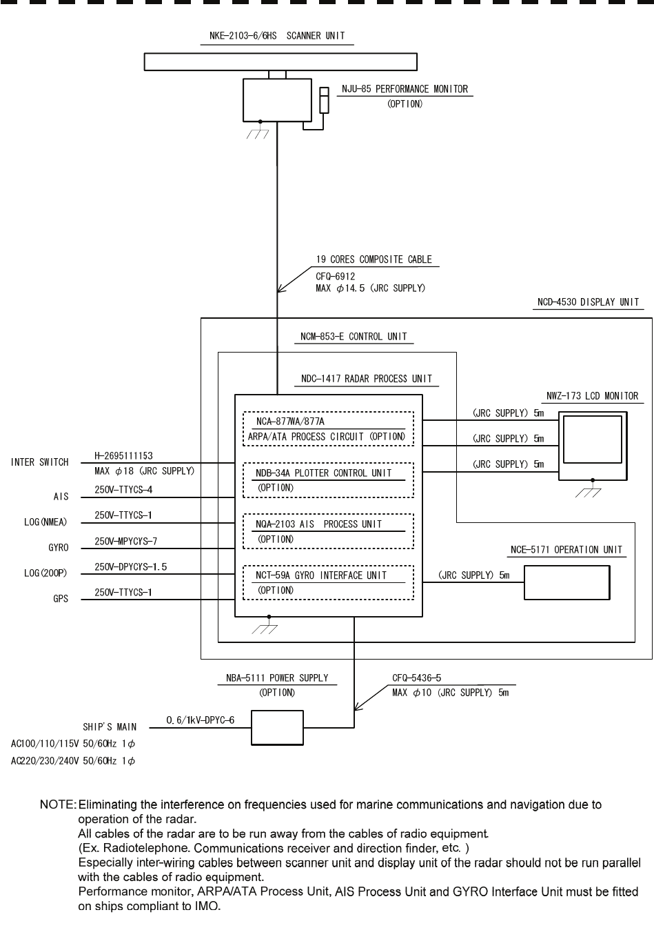
Fig. 1.10 General System Diagram of Radar, Type JMA-5312-6 / 6HS
1-17
1.5 General System Diagrams y
1
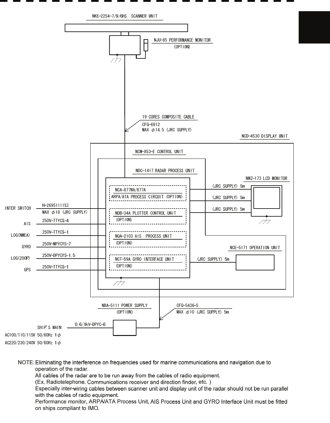
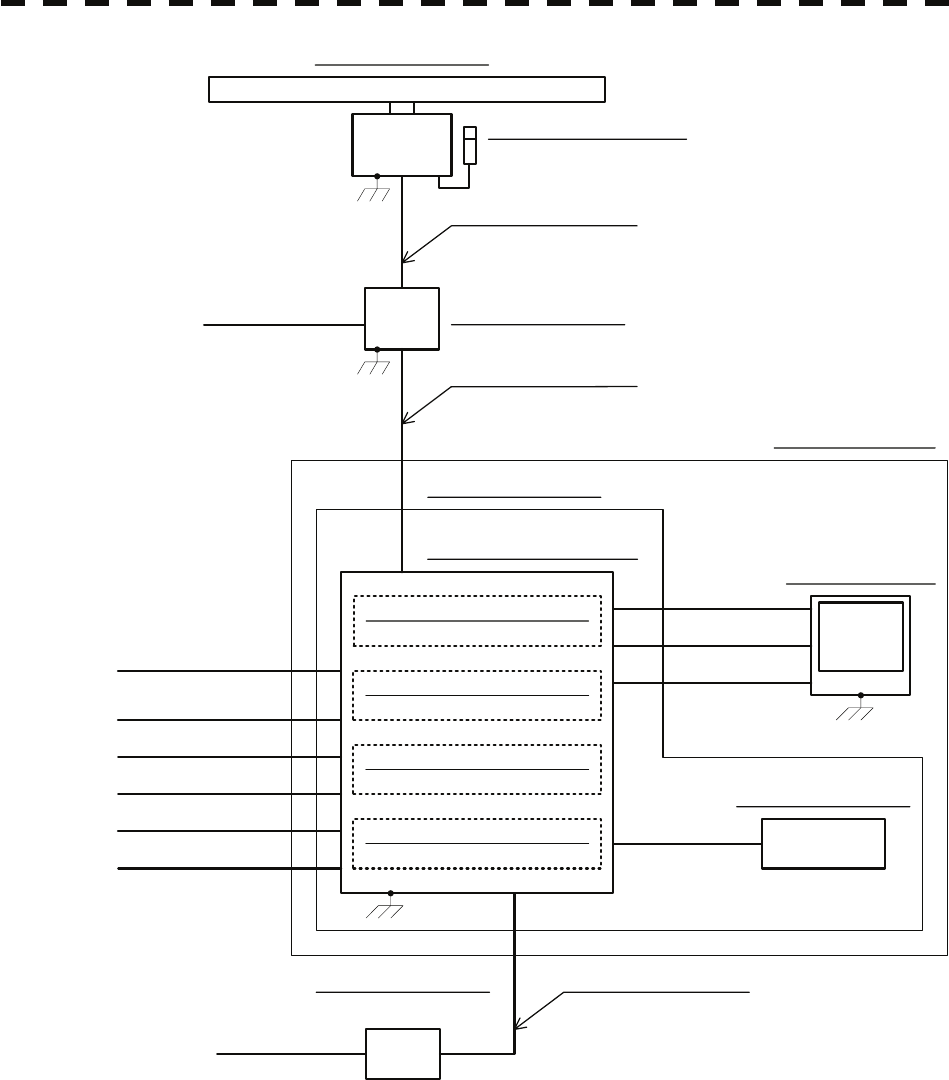
Fig. 1.11 General System Diagram of Radar, Type JMA-5322-7 / 9 / 6HS
1-18
CFQ-6912
MAX φ14.5 (JRC SUPPLY)
19 CORES COMPOSITE CABLE
NQE-3151A JUNCTION BOX
H-2695110056
MAX φ23 (JRC SUPPLY)
14 CORES COMPOSITE CABLE
NJU-84 PERFORMANCE MONITOR
0.6/1kV-DPYC-1.5
SHIP'S MAIN
AC100/110/115V 50/60Hz 1φ
AC220/230/240V 50/60Hz 1φ
NKE-1130 SCANNER UNIT
NCM-853-E CONTROL UNIT
NCE-5171 OPERATION UNIT
NCA-877WA/877A (JRC SUPPLY) 5m
NWZ-173 LCD MONITOR
NDC-1417 RADAR PROCESS UNIT
NCD-4530 DISPLAY UNIT
(JRC SUPPLY) 5m
(JRC SUPPLY) 5m
0.6/1kV-DPYC-6
CFQ-5436-5
MAX φ10 (JRC SUPPLY) 5m
NBA-5111 POWER SUPPLY
(OPTION)
GYRO
LOG(200P)
250V-TTYCS-4
250V-TTYCS-1
250V-MPYCYS-7
250V-DPYCYS-1.5
250V-TTYCS-1
GPS
SHIP'S MAIN
AC100/110/115V 50/60Hz 1φ
AC220/230/240V 50/60Hz 1φ
H-2695111153
MAX φ18 (JRC SUPPLY)
INTER SWITCH
AIS
LOG(NMEA)
(JRC SUPPLY) 5m
ARPA/ATA PROCESS CIRCUIT (OPTION)
(OPTION)
NCT-59A GYRO INTERFACE UNIT
NQA-2103 AIS PROCESS UNIT
NDB-34A PLOTTER CONTROL UNIT
(OPTION)
(OPTION)
(OPTION)
NOTE:Eliminating the interference on frequencies used for marine communications and navigation due to
operation of the radar.
All cables of the radar are to be run away from the cables of radio equipment.
(Ex. Radiotelephone. Communications receiver and direction finder, etc. )
Especially inter-wiring cables between scanner unit and display unit of the radar should not be run parallel
with the cables of radio equipment.
Performance monitor, ARPA/ATA Process Unit, AIS Process Unit and GYRO Interface Unit must be fitted
on ships compliant to IMO.
Fig. 1.12 General System Diagram of Radar, Type JMA-5332-12
1-19

SECTION 2
NAMES AND FUNCTIONS OF CONTROL
PANEL KEYS AND FUNCTIONS OF
SOFTWARE BUTTONS
2.1 NAMES OF DISPLAY...............................................................................2-1
2.2 NAMES AND FUNCTIONS OF CONTROL PANEL KEYS ....................2-10
2.3 FUNCTIONS OF SOFTWARE BUTTONS .............................................2-15
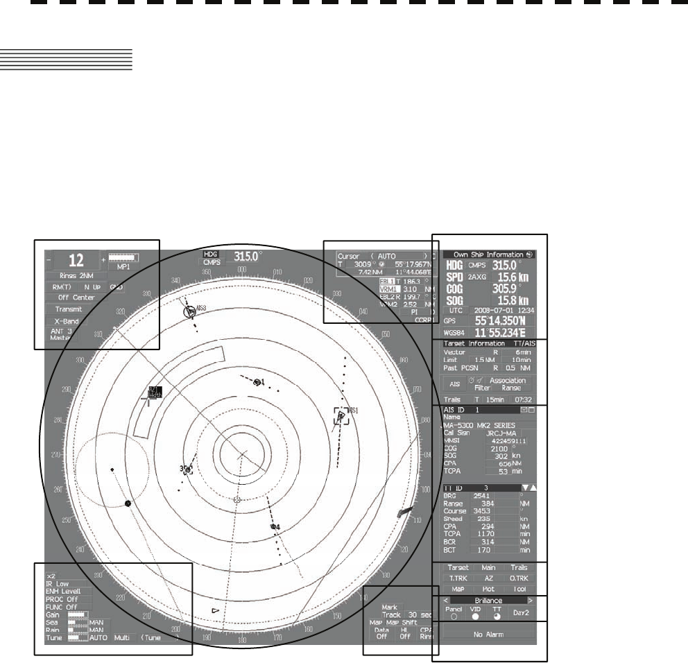
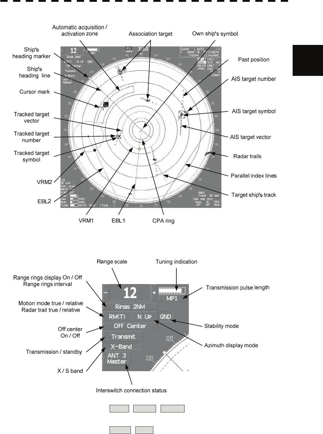
2.1 NAMES OF DISPLAY
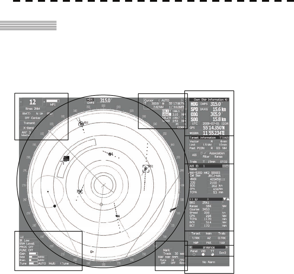
Example of screen display
In this example, the screen is divided into a number of areas and the names in each area are
indicated.
PPI
Upper left
of the display
Lower left
of the display
Upper right
of the display
Lower right
of the display
Own ship's
information
Digital information
Target
tracking (TT) /
AIS information
Menu
Brilliance /
Display information
Alarm
2-1
2
2.1 Names of Dis
p
la
y
yy
PPI
Upper left of the display
About ground and sea stabilization
Speed sensor source is MAN , 1AXW , 2AXW
If Set/Drift Setting menu is on : GND (Ground stabilization)
If Set/Drift Setting menu is off : Sea (Sea stabilization)
Speed sensor source is 2AXG , GPS : GND (Ground stabilization)
2-2
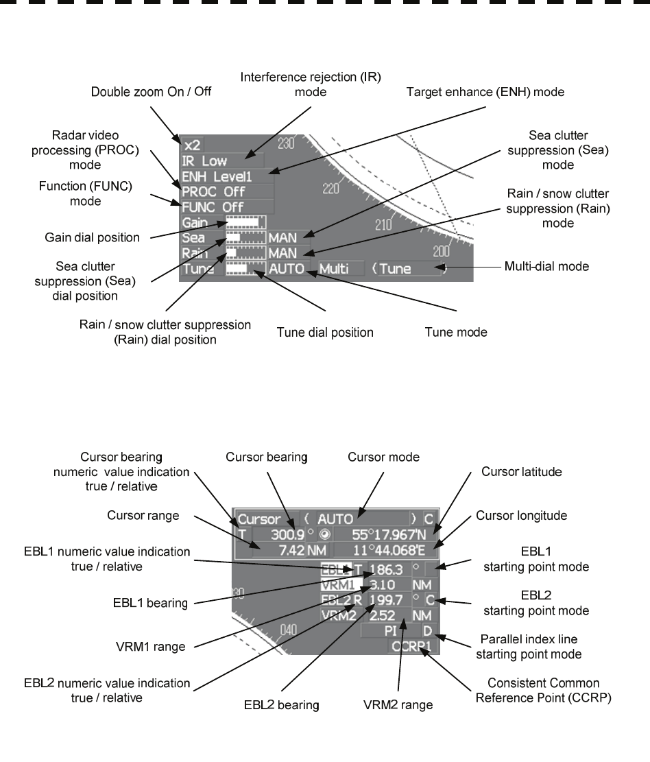
Lower left of the display
Upper right of the display
2-3
2
2.1 Names of Dis
p
la
y
yy
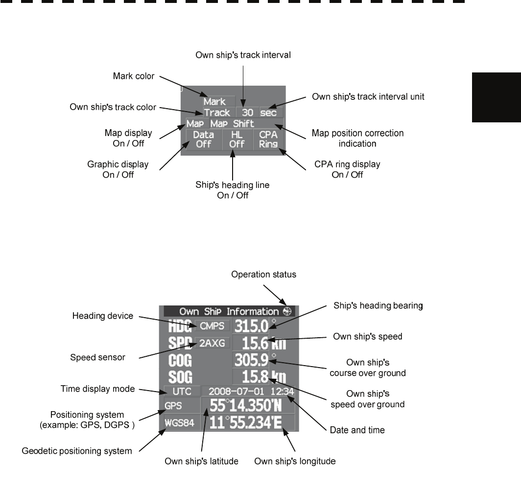
Lower right of the display
Own ship's information
2-4
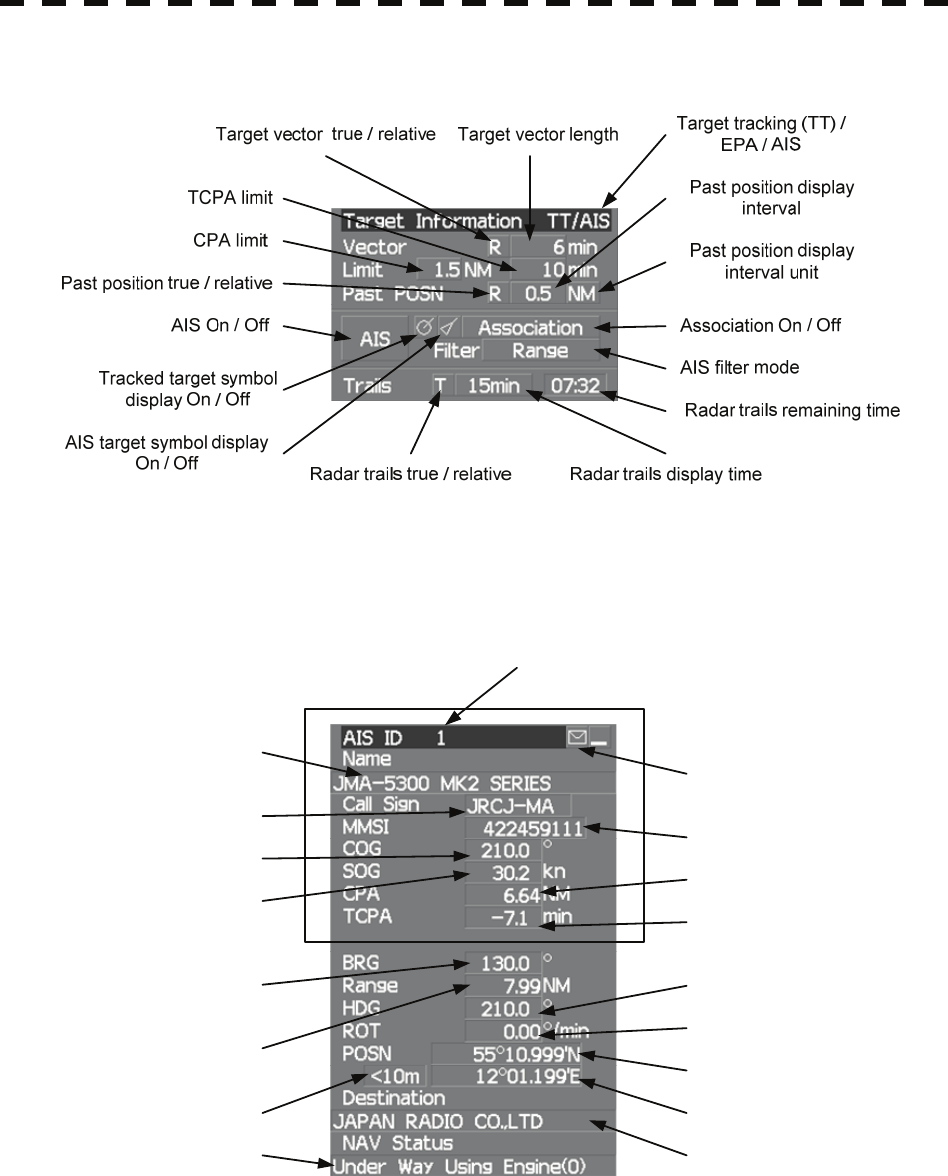
Target tracking (TT) / AIS information
Digital information: AIS target information
Ship's name
Call sign MMSI
Course
Speed CPA
TCPA
Bearing
Range
Ship's heading bearing
Rate of turn
Latitude
Longitude
DestinationNavigation status
Latitude / longitude error
Simple display item
AIS target number
Unread message
2-5
2
2.1 Names of Dis
p
la
y
yy
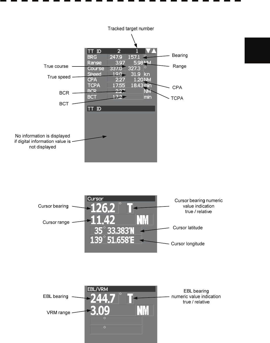
Digital information: Tracked target information
Digital information: Enhancement of cursor position numeric value indication
Digital information: Enhancement of EBL / VRM numeric value display
2-6
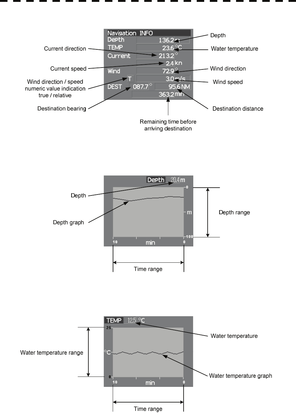
Digital information: Navigation information
Digital information: Depth indication
Digital information: Water temperature indication
2-7
2
2.1 Names of Dis
p
la
y
yy
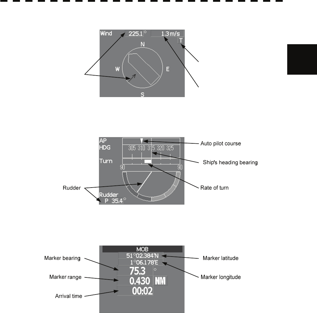
Digital information: Wind direction / speed
Wind speed
Wind direction / speed
true / relative
Wind direction
Digital information: Course bar
Digital information: Marker
2-8
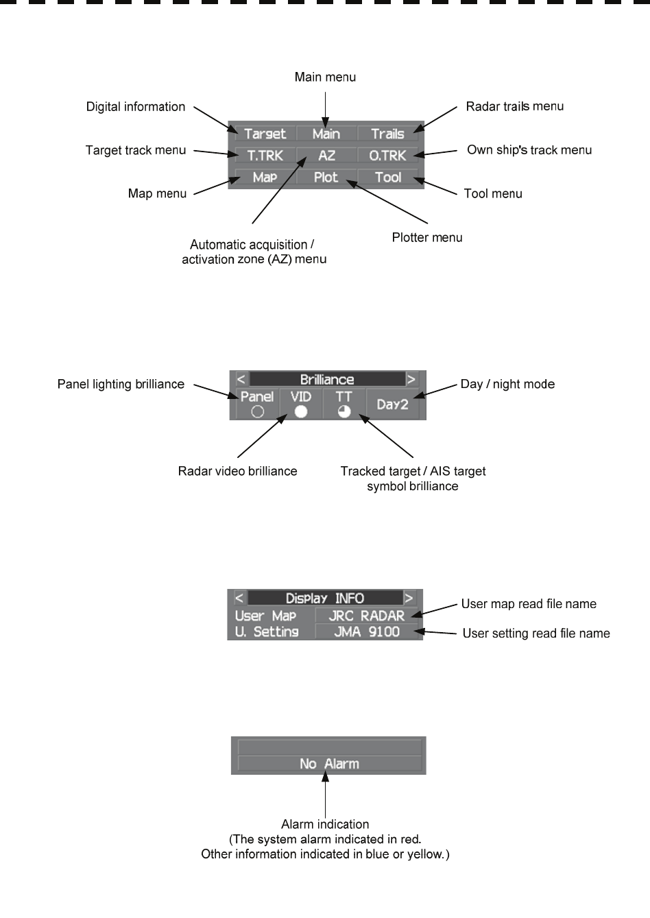
Menu
Brilliance
Display information
Alarm
2-9
2
2.2 Names and Functions of Control Panel Ke
y
syy
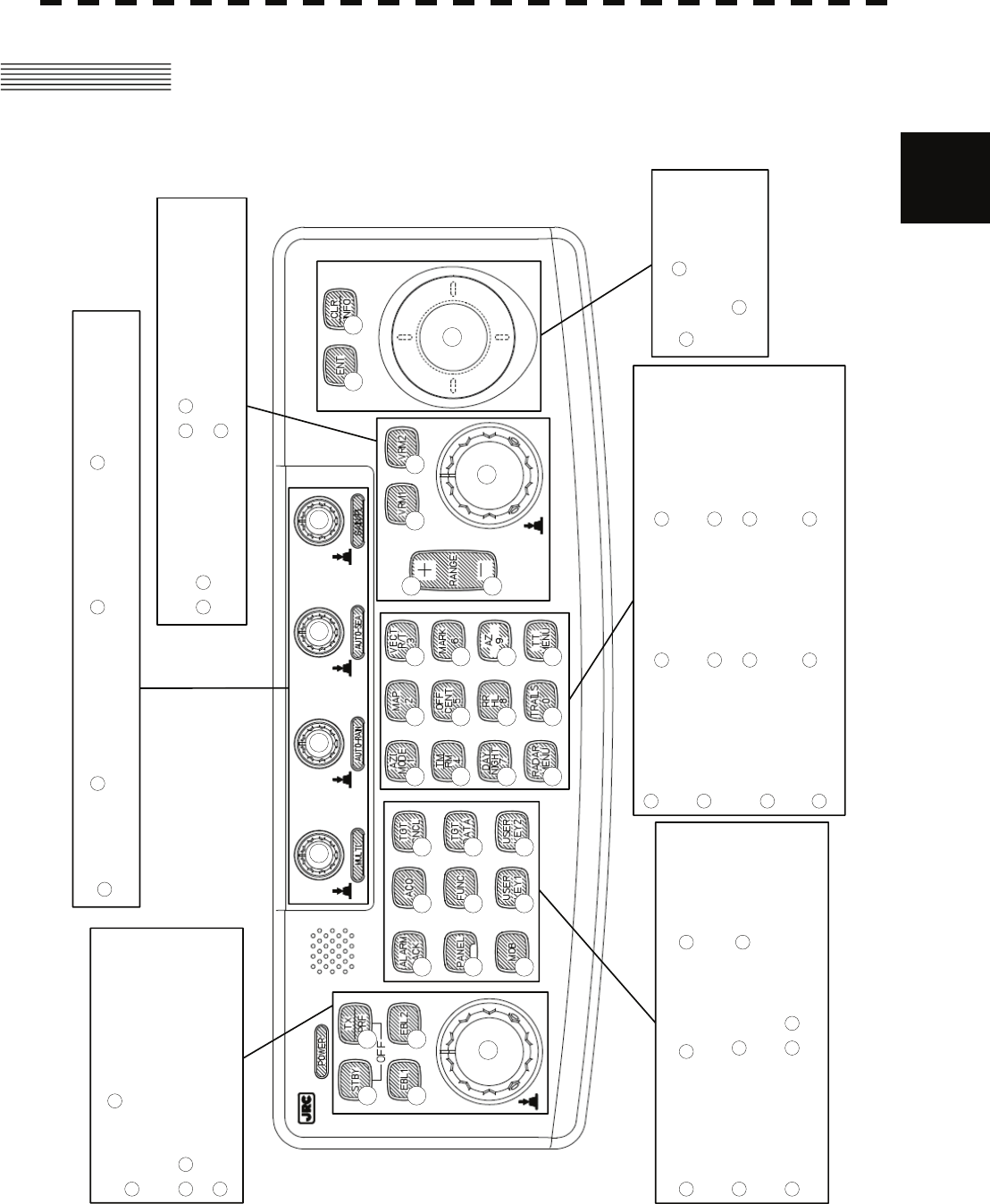
2.2 NAMES AND FUNCTIONS OF CONTROL
PANEL KEYS
1
23
4 5 6 7
8 9
10
2019
18 17
1615
14
13
12
11 21 22 23
24 25 26
27 28 29
3031 32
33
34
35 36
37 38
Multi dial
Enter
Electronic bearing line dial
Function
call
/ User registration 1 / 2
Transmission /
transmission repetition
frequency
Alarm
acknowledgment
/ Electronic bearing line 1 / 2
Standby
Automatic - Rain /
snow clutter dial Automatic - Sea
clutter dial Gain / pulse length
dial
Marker
Control panel
brilliance Target data
indication
Tracked target
cancellation
Manual
acquisition
Azimuth display
mode / 1
Day / night / 7
True / relative
motion / 4
Map / 2
Range rings /
ship’s heading line
cancellation / 8
Off-center / 5
Vector mode / 3
Automatic
acquisition /
activation zone / 9
Mark / 6
Main menu Radar trails / 0 Target tracking
(TT) menu
Clear /
information
2
456 7
8
9
10
2019
18 17
1615
14
13
12
11
22 23
24 25 26
27
28 29
30
31 32
37 38
21
Track ball
1
/ Variable range marker 1 / 2
Variable range marker dial
/ Range scale + / -
3
33 34
35 36
The name of each button is described from the following page. See below.
2-10
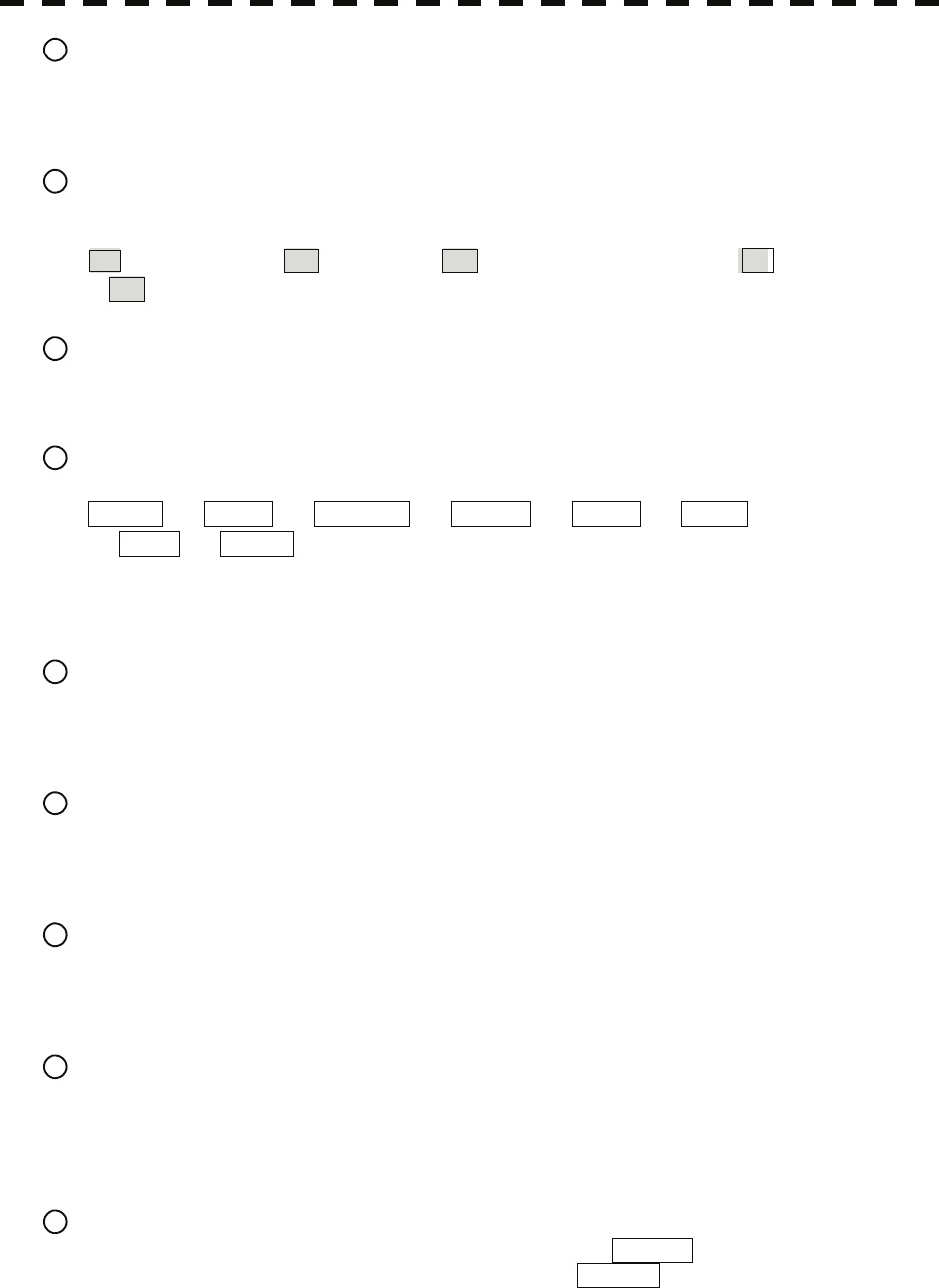
1 Track ball
Use the track ball to move the cursor mark to any position.
For example, use it for setting in each mode and specifying a floating EBL center position and off-center
position.
2 [EBL] (Electronic Bearing Line) dial
Turn the dial to rotate the bearing of the EBL.
By pressing the dial, the selected EBL can be switched.
(Center fixing) ⇒ C (Floating) ⇒ D (latitude / longitude fixing) ⇒
* D is enabled only when the navigator is connected.
3 [VRM] (Variable Range Marker) dial
Turn the dial to change the VRM range.
Press the dial to set the display of parallel index line (PI) to On / Off and open the PI Menu.
4 [MULTI] dial
Press the dial to switch the function that is registered in the multi-dial.
Vector ⇒ Trails ⇒ TGT No. ⇒ Course ⇒ Track ⇒ Mark
⇒ Tune ⇒ Vector
The function that is switched is displayed in multi-dial mode (lower left of the display on page 2-3)
If the dial is pressed for 2 seconds, the Multi Dial Setting menu is opened. If the dial is pressed again for 2
seconds, the setting menu is closed.
5 [AUTO-RAIN] (Automatic - Rain / Snow clutter suppression) dial
Turn the dial to suppress images by rain / snow clutter.
Turn the dial clockwise to increase the effect of suppression.
Press the dial to switch the mode to manual / automatic.
6 [AUTO-SEA] (Automatic - Sea clutter suppression) dial
Turn the dial to suppress images by sea clutter.
Turn the dial clockwise to increase the effect of suppression.
Press the dial to switch the mode to manual / automatic.
7 [GAIN / PL] (Gain / Pulse Length) dial
Turn the dial to adjust the reception gain of the radar.
Turn the dial clockwise to increase the gain.
Press the dial to switch the transmitting pulse length.
8 [STBY] (Standby) key
Use this key to turn on the power of the equipment.
Use this key also to switch the equipment from a transmitting state to a standby state.
The power can be turned off by pressing the [STBY] key and [TX / PRF] key concurrently while the
power is On.
9 [TX / PRF] (Transmission / transmission repetition frequency) key
At expiration of the pre-heat time after the power is turned on, Preheat of the transmission / standby
indication (Upper left of the display on page 2-2) changes to Standby .
If this key is pressed subsequently, transmission starts.
If this key is pressed during transmission, fine adjustments of the transmission repetition frequency are
enabled.
By using the fine adjustments of the transmission repetition frequency and the interference removal
function, the interference suppression effect can be improved.
2-11
2
2.2 Names and Functions of Control Panel Ke
y
syy
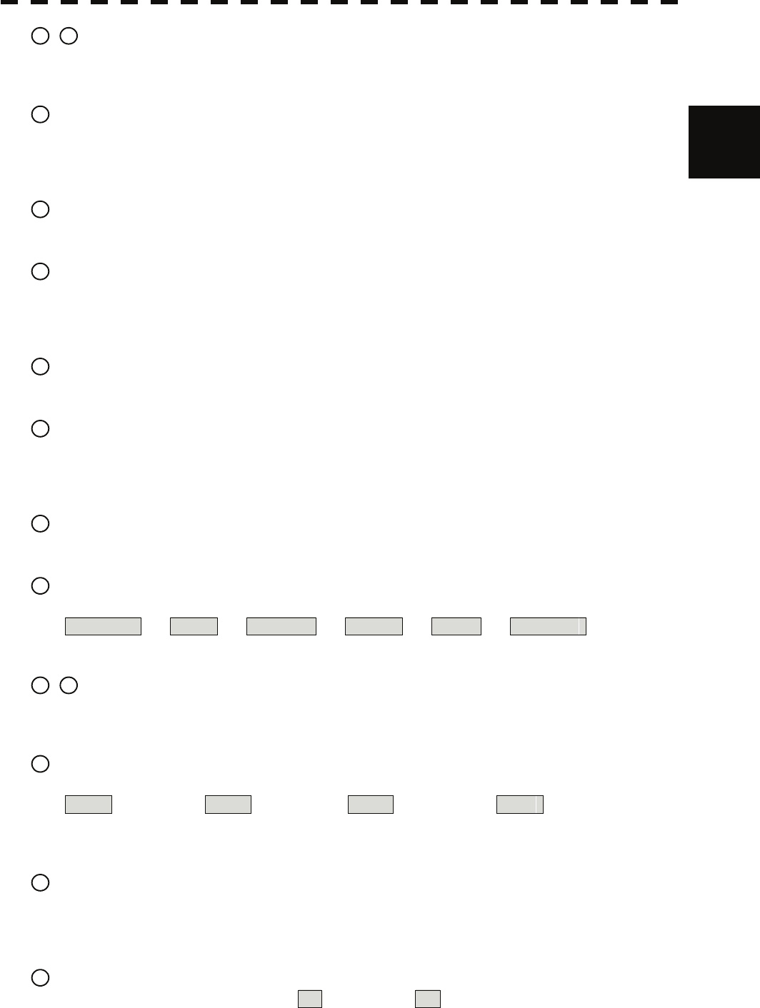
10 / 11 [EBL1] / [EBL2] (Electronic Bearing Line 1 / 2) key
Use these keys to switch EBL1 / EBL2 to On / Off.
If the key is pressed for 2 seconds, the EBL / Cursor Setting menu is opened.
12 [ALARM ACK] (Alarm acknowledgment) key
Use this key to acknowledge the alarm such as a failure alarm and a collision alarm.
To stop the alarm, press this key while the alarm sound is emitted.
If multiple alarms occur, press this key same time as the alarms.
13 [PANEL] (Control panel brilliance) key
Use this key to adjust the brilliance of various keys and dials on the control panel.
14 [MOB] (Marker) key
A marker is set on the own ship's position latitude / longitude at that time. Use this key to store the own
ship's position at the time in such a case that someone falls overboard from the ship.
The marker can be cleared by pressing the key for 2 seconds.
15 [ACQ] (Manual acquisition) key
Use this key to acquire a target of the cursor position manually.
16 [TGT CNCL] (Tracked target cancellation) key
Use this key to cancel the tracked target symbol / vector at the cursor position and stop tracking.
When this key is pressed for 2 seconds, all the tracked target symbols / vectors are cancelled and tracking
is stopped.
17 [TGT DATA] (Target data indication) key
Use this key to check the digital information of the AIS target or the tracked target.
18 [FUNC] (Function call) key
Use this key to switch the original signal processing settings.
FUNC Off ⇒ Coast ⇒ Deep Sea ⇒ Fishnet ⇒ Storm ⇒ FUNC Off
If the key is pressed for 2 seconds, the User Function Setting menu is displayed.
19 / 20 [USER KEY 1 / 2] (User registration 1 / 2) key
Use this key to perform pre-registered operations.
If this key is pressed for 2 seconds while no operation is registered, the User Key Setting menu is opened.
21 [AZI MODE / 1] (Azimuth display mode / 1) key
Switch the azimuth display.
H Up (Head Up) ⇒ N Up (North Up) ⇒ C Up (Course Up) ⇒ N Up
During the menu operation, the key functions as a numeric key [1].
If this key is pressed for 2 seconds, GYRO setting menu is opened.
22 [MAP / 2] key
Use this key to switch the map display to On / Off such as marine chart, coastline, and depth contour.
During the menu operation, the key functions as a numeric key [2].
If this key is pressed for 2 seconds, the Map Setting menu is opened.
23 [VECT R / T / 3] (Vector mode / 3)
Use this key to switch vector indication T (true vector) / R (relative vector).
During the menu operation, the key functions as a numeric key [3].
2-12

24 [TM / RM / 4] (True Motion / Relative Motion / 4) key
Use this key to switch the motion mode between TM (true motion) and RM (relative motion).
If the key is pressed for 2 seconds in TM , the own ship's position is reset.
During the menu operation, the key functions as a numeric key [4].
25 [OFF CENT / 5] (Off-center / 5) key
By pressing this key, moving the cursor, and pressing the [ENT] key, the ship's position can be moved to
the cursor position. The moving range is about 66% of the radius.
If the key is pressed for 2 seconds, the off-center is set to Off and the ship's position is returned to the
center of the screen.
During the menu operation, the key functions as a numeric key [5].
26 [MARK / 6] (Mark / 6) key
Use this key to display a mark in any screen position. This key can also be used for clearing the mark that
is currently displayed.
If the key is pressed for 2 seconds, the Mark Setting menu is opened.
During the menu operation, the key functions as a numeric key [6].
27 [DAY / NIGHT / 7] (Day / night mode / 7) key
Use this key to switch the color and brightness of the screen that have been set in advance.
If the key is pressed for 2 seconds, the Display Color Setting menu is opened.
During the menu operation, the key functions as a numeric key [7].
28 [RR / HL / 8] (Range Rings / ship's heading line off / 8) key
Use this key to set the range rings marker to On / Off.
If the key is pressed for 2 seconds, the ship's heading line is cleared while the key is pressed.
During the menu operation, the key functions as a numeric key [8].
29 [AZ / 9] (Automatic Acquisition / Activation Zone / 9) key
Use this key to set automatic acquisition / activation zone.
If the key is pressed for 2 seconds, the AZ Menu (automatic acquisition / activation zone menu) is opened.
During the menu operation, the key functions as a numeric key [9].
30 [TRAILS / 0] (Radar trails / 0) key
Use this key to switch the length of the radar trail period.
If the key is pressed for 2 seconds, the RADAR Trails setting menu is opened.
If this key is pressed for 5 seconds, the radar trail is cleared.
During the menu operation, the key functions as a numeric key [0].
31 [RADAR Menu] (Main menu) key
Use this key to open the Main Menu.
32 [TT Menu] key
Use this key to open the TT Menu (target tracking menu).
33 / 34 [RANGE + / - ] key
Press the [+] key to increase the observation range and the [-] key to reduce the observation range.
35 / 36 [VRM 1 / 2 ] (Variable Range Marker 1 / 2) key
Use this key to set the display of VRM1 / VRM2 to On / Off and acquire the operation right.
2-13

2
2.2 Names and Functions of Control Panel Ke
y
syy
37 [ENT] (Enter) key
Use this key to confirm menu selection and input of numeric values.
This key is equivalent to the clicking of the left button of the track ball.
38 [CLR / INFO] (Clear / information) key
Use this key to cancel menu selection or numeric value input.
This key is equivalent to the clicking of the right button of the track ball.
2-14
2.3 FUNCTIONS OF SOFTWARE BUTTONS
In this radar, the frequently used functions can be directly set from the screen without opening the menu
by using the software buttons on the screen for quick handling. The screen is divided into a number of
areas and each area is named.
PPI
Upper left
of the display
Lower left
of the display
Upper right
of the display
Lower right
of the display
Own ship's
information
Digital information
Target
tracking (TT) /
AIS information
Menu
Brilliance /
Display information
Alarm
The name of each button is described from the next page. The function can be used by pressing (clicking)
the [ENT] key while setting the arrow cursor on the button position.
2-15
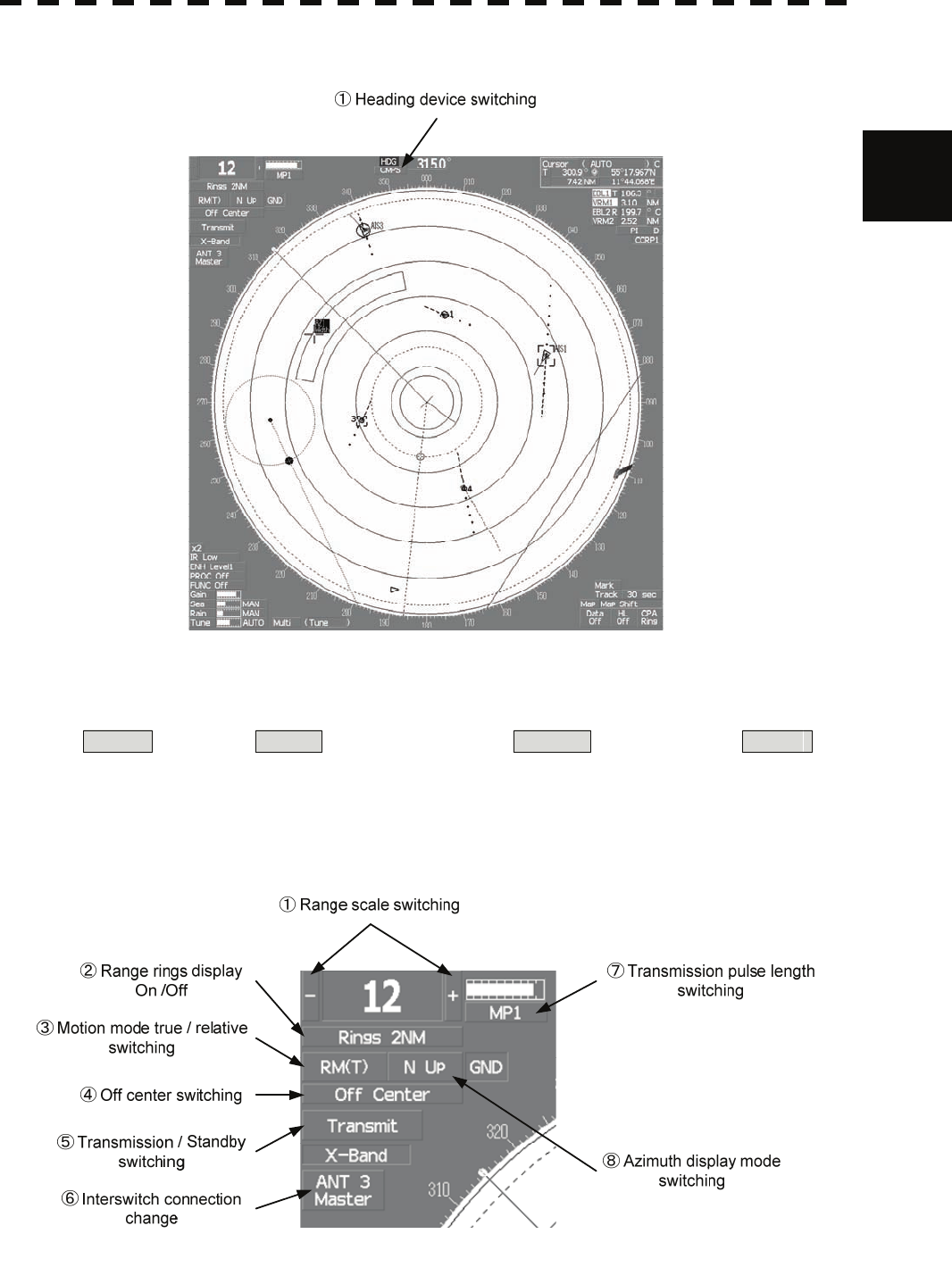
2.3 Functions of Software Buttons yy
PPI
2
①:Heading device switching
This function switches the heading device.
GYRO (GYRO) ⇒ CMPS (Electronic compass) ⇒ G.COM (GPS compass) ⇒ GYRO
If the selected heading device is not connected to the equipment, an alarm is issued.
Upper left of the display
2-16
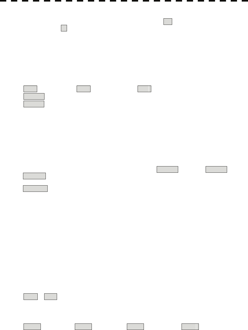
①:Range scale switching
To increase the observation range scale (maximum 96NM), click + and to reduce the range (minimum
0.125NM), click - .
②:Range rings display On / Off
The display of range rings are set to On / Off whenever this button is clicked.
When the display is set to On, the interval of the fixed range marker is displayed.
③:Motion mode true / relative switching
The screen motion mode is switched whenever the button is clicked.
TM (true motion) ⇒ RM (relative motion) ⇒ TM
RM(R) indicates that the radar trails is a relative trail.
RM(T) indicates that the radar trails is a true trail.
④:Off center switching
If this button is clicked, the cursor is moved, and the [ENT] key is pressed, the ship's position can be
moved to the cursor position. The moving range is within 66% of the radius.
If the button is clicked for 2 seconds, the off-center is set to Off and the ship's position is returned to the
center of the screen.
⑤:Transmission / standby switching
At expiration of the pre-heat time after the power is turned on, Preheat changes to Standby .
Standby : Indicates a standby state. If this button is clicked in this state, the equipment is set to a
transmission state.
Transmit : Indicates a transmission state. If this button is clicked in this state, the equipment is set to a
standby state.
⑥:Interswitch connection change
This button is displayed when the interswitch is connected. This button indicates the connection status of
the scanner unit that is connected to the indicator.
If the button is clicked in the transmission standby state, the menu for changing the connection state
between the scanner unit and the indicator is displayed. The connection state of the scanner unit and
indicator cannot be changed unless the master indicator is in a standby state.
→ Refer to the Interswitch (Optional) Instruction Manual that is attached for the setting method. This
button is not displayed if the interswitch is not connected.
⑦:Transmission pulse length switching
The transmission pulse length is switched whenever this button is clicked. Three types of pulses are
available, short pulse (SP), middle pulse (MP), and long pulse (LP). The pulse length and repetition
frequency vary even for the same short pulse, according to the range that is used and it is displayed as
SP1 , SP2 .
⑧:Azimuth display mode switching
The azimuth display is switched whenever this button is clicked.
H Up (Head Up) ⇒ N Up (North Up) ⇒ C Up (Course Up) ⇒ H Up
If the button is clicked for 2 seconds, the GYTO Setting menu is displayed.
2-17
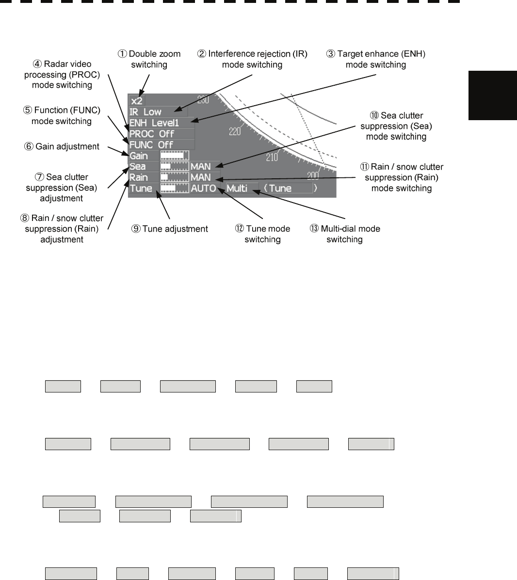
2.3 Functions of Software Buttons yy
Lower left of the display
2
①:Double zoom switching
Use this function to enlarge to double the size the display screen of the position specified by the cursor.
If this button is clicked, the zoom mode is set. When the cursor is moved to the radar screen and the
[ENT] key is pressed, the screen is enlarged to double the size so that the middle of the cursor and the own
ship's position is set to the center of the screen. This function cannot be used when the range is 0.125NM.
②:Interference rejection (IR) mode switching
The interference rejection mode is switched whenever this button is clicked.
IR Off ⇒ IR Low ⇒ IR Medium ⇒ IR High ⇒ IR Off
③:Target enhance (ENH) mode switching
The target enhance mode is switched whenever this button is clicked.
ENH Off ⇒ ENH Level1 ⇒ ENH Level2 ⇒ ENH Level3 ⇒ ENH Off
④:Radar video processing (PROC) mode switching
The radar video processing mode is switched whenever this button is clicked.
PROC Off ⇒ 3Scan CORREL ⇒ 4Scan CORREL ⇒ 5Scan CORREL ⇒
⇒ Remain ⇒ Peak Hold ⇒ PROC Off
⑤:Function (FUNC) mode switching
The function mode is switched whenever this button is clicked.
FUNC Off ⇒ Coast ⇒ Deep Sea ⇒ Fishnet ⇒ Storm ⇒ FUNC Off
If the button is clicked for 2 seconds, the function registration menu (User Function Setting) is opened.
⑥, ⑦, ⑧,and ⑨:Gain, Sea clutter suppression (Sea), Rain / snow clutter
suppression (Rain), Tune adjustment
Adjust the gain, sea clutter suppression, rain and snow clutter suppression and tune using the track ball.
If the button is clicked on, the adjustment value is shown at the upper-right of the cursor. Make
adjustments by moving the track ball to the left and right. Determine the adjustment by pressing the [ENT]
key.
2-18
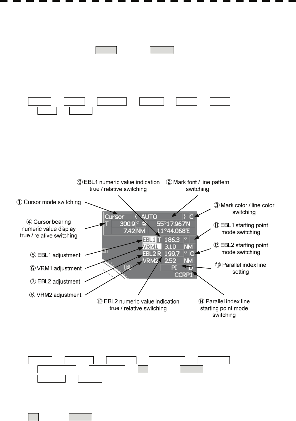
⑩, ⑪,and ⑫:Sea clutter suppression (Sea) mode, Rain / snow clutter
suppression (Rain) mode, and Tune mode switching
Use these functions to switch to the manual or automatic mode of sea clutter suppression, rain / snow
clutter suppression and tune. The bar on the left side indicates the position of the dial.
The mode is switched to MAN (manual) / AUTO (automatic) whenever the button is clicked. If
rain / snow clutter suppression is switched to an automatic mode, sea clutter suppression is switched to an
automatic mode also.
⑬:Multi-dial mode switching
The function that is registered in the multi-dial is switched whenever the button is clicked.
Vector ⇒ Trails ⇒ TGT No. ⇒ Course ⇒ Track ⇒ Mark ⇒
⇒ Tune ⇒ Vector
The switched function is displayed in ( ).
If the button is clicked for 2 seconds, the Multi Dial Setting menu is opened. If this button is clicked again
for 2 seconds, this setting menu is closed.
Upper right of the display
①:Cursor mode switching
The mode of the function that uses the cursor is switched whenever this button is pressed.
AUTO ⇒ ACQ TT ⇒ ACT AIS ⇒ TGT DATA ⇒ CNCL TT ⇒
⇒ DEACT AIS ⇒ CNCL Data ⇒ □ (Mark) ⇒ -------- (Line) ⇒
⇒ Property ⇒ AUTO
②:Mark font / line pattern switching
This function switches a mark font / line pattern. If this button is clicked while the cursor mode is
□ (mark) or -------- (line), the mark font / line pattern is changed.
2-19
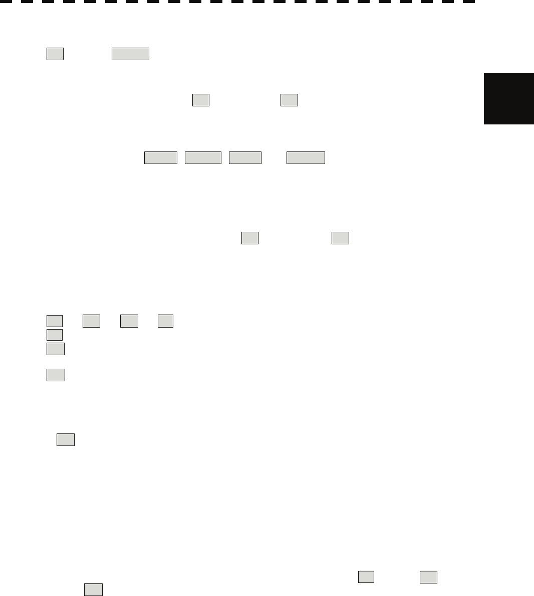
2.3 Functions of Software Buttons yy
③:Mark color / line color switching
This function switches a mark color / line color. If this button is clicked while the cursor mode is
□ (mark) or -------- (line), the mark color / line color is changed.
2
④:Cursor bearing numeric value display true / relative switching
The bearing numeric value display T (true bearing) / R (relative bearing) of the cursor is switched
whenever this button is clicked.
⑤, ⑥, ⑦,and ⑧:EBL1 / 2 and VRM1 / 2 adjustment
These functions set the EBL1 , VRM1 , EBL2 , and VRM2 displays to On / Off and acquire the
operation right.
If the button is clicked on, the operation right is acquired. Make adjustments by moving the track ball to
the left and right Determine the adjustment by pressing the [ENT] key.
⑨ and ⑩:EBL1, EBL2 numeric value true / relative switching
The EBL1 / 2 bearing numeric value display T (true bearing) / R (relative bearing) is switched
whenever the button is clicked.
If the button is clicked for 2 seconds, the EBL / Cursor Setting menu is displayed.
⑪ and ⑫:EBL1 / EBL2 starting point mode switching
The EBL starting point is set to CCRP or any position on the radar screen whenever this button is clicked.
⇒ C ⇒ D ⇒
: Center :The starting point is fixed to the CCRP position.
C : Screen Fix :The starting point is set to the cursor position. If the [ENT] key is pressed
subsequently, the starting position is fixed to the cursor position.
D : L/L Fix :The starting point is set to the cursor position. If [ENT] key is pressed
subsequently, the starting position is fixed to the latitude / longitude of the cursor.
(Connection of a navigator is necessary.)
If the starting point is moved outside of the screen, the operation is reset
automatically and the starting point returns to the CCRP position.
* D is enabled only when a navigator is connected.
⑬:Parallel index line setting
This function sets the parallel index line display to On / Off and acquires the operation right.
If this button is clicked, the operation right is acquired and the menu is opened. After setting, determine
the setting by pressing the [ENT] key.
⑭:Parallel index line starting point mode switching
The parallel index line starting point is set to CCRP or any position on the radar screen whenever this
button is clicked.
In the same way as for the EBL starting point, three options are available, : Center, C : Screen
Fix, and D : L/L Fix.
2-20
Lower right of the display
②Own ship's track interval
switching
④Map display
On / Off
⑤Graphic display Off
⑥Ship's heading line Off
③Own ship's track interval unit
switching
⑦CPA ring display
On / Off
①Mark color switching
①:Mark color switching
The color of the mark is switched whenever this button is clicked.
If the button is clicked for 2 seconds, the Mark Setting menu is opened.
②:Own ship's track interval switching
The own ship's track interval is switched whenever this button is clicked.
③:Own ship's track interval unit switching
The unit of the own ship's track interval is switched whenever this button is clicked.
sec ⇒ min ⇒ NM ⇒ sec
④:Map display On / Off
The map display is set to On / Off whenever this button is clicked.
Map information must be inserted in the card slot of the radar process unit in advance.
If the button is clicked for 2 seconds, the Map Setting menu is opened.
⑤:Graphic display Off
While the button is clicked, the graphic display other than VRM, EBL, HL, a cursor, and range rings on
the radar screen is cleared temporarily.
⑥:Ship's heading line Off
The ship's heading line (HL) display is set to Off while this button is clicked.
Since the ship's heading line is cleared while the button is clicked, the target in the ship's heading bearing
can be clearly seen.
⑦:CPA ring display On / Off
The CPA ring display is switched to On / Off whenever the button is clicked.
When the target vector display mode is T (true vector), the CPA ring cannot be set to On.
2-21
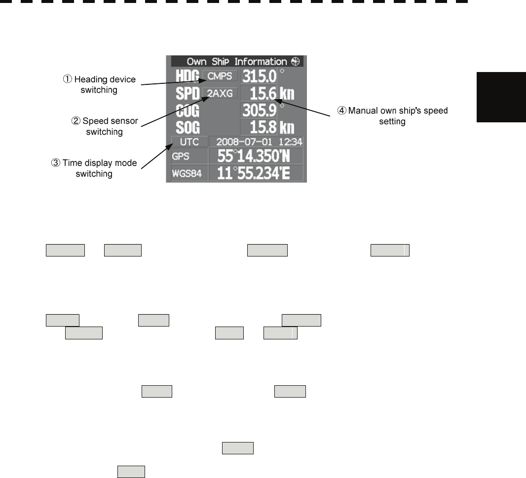
2.3 Functions of Software Buttons yy
Own ship's information
2
①:Heading device switching
The heading device is switched whenever this button is clicked.
GYRO ⇒ CMPS (Electronic compass) ⇒ GCOM (GPS compass) ⇒ GYRO
When the selected heading device is not connected to the equipment, an alarm is issued.
②:Speed sensor switching
The speed sensor is switched whenever the button is clicked.
MAN (Manual) ⇒ LOG (Single-axis water log) ⇒ 2AXW (Dual-axis water log)
⇒ 2AXG (Dual-axis ground log) ⇒ GPS ⇒ MAN
When the selected speed device is not connected to the equipment, an alarm is issued.
③:Time display mode switching
The time display mode UTC (universal time clock) / LMT (local mean time) is switched whenever
this button is clicked.
④:Manual own ship's speed setting
When selection of the speed sensor is set to MAN , enter the own ship's speed manually.
If this button is clicked, the numeric value input screen is opened. After setting a value, determine the
entry by clicking ENT .
2-22
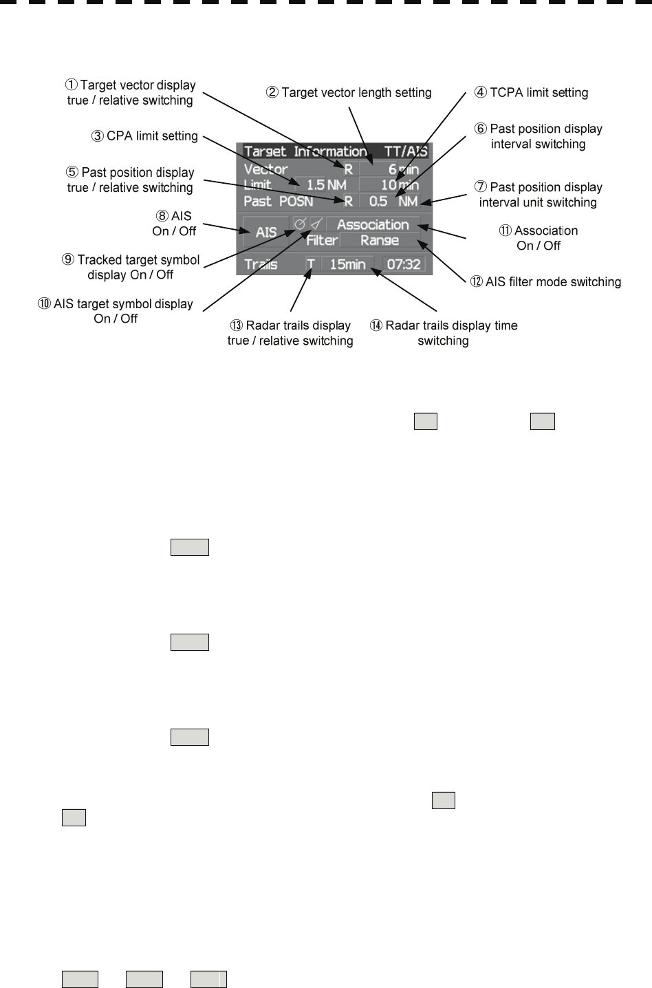
Target tracking (TT) / AIS information
①:Target vector display true / relative switching
The tracked target / AIS target vector display is switched to T (true vector) / R (relative vector)
whenever this button is clicked.
This setting is switched together with the past position display true / relative switching.
②:Target vector length setting
Set a vector length of the tracked target / AIS target.
If this button is clicked, the numeric value input screen is opened. After setting the length, determine the
setting by clicking ENT .
③:CPA limit setting
Set a CPA limit.
If this button is clicked, the numeric value input screen is opened. After setting the limit, determine the
setting by clicking ENT .
④:TCPA limit setting
Set a TCPA limit.
If this button is clicked, the numeric value input screen is opened. After setting the limit, determine the
setting by clicking ENT .
⑤:Past position display true / relative switching
The tracked target / AIS target past position display is switched to T (true past position) /
R (relative past position) whenever the button is clicked.
This setting is switched together with the target vector display true / relative switching.
⑥:Past position display interval switching
The past position display interval is switched whenever the button is clicked.
⑦:Past position display interval unit switching
The past position display interval unit is switched whenever the button is clicked.
min ⇒ NM ⇒ min
2-23
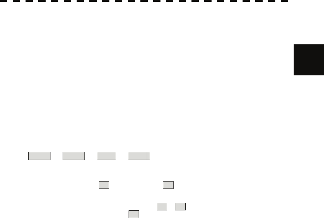
2.3 Functions of Software Buttons yy
⑧:AIS On / Off
The AIS display is switched to On / Off whenever the button is clicked.
⑨:Tracked target symbol display On / Off 2
The tracked target symbol display is switched to On / Off whenever the button is clicked. Use this function
to avoid confusion with the AIS symbol.
⑩:AIS target symbol display On / Off
The AIS target symbol display is switched to On / Off whenever the button is clicked. Use this function to
avoid confusion with the tracked target symbol.
⑪:Association On / Off
The tracked target / AIS target association is switched to On / Off whenever the button is clicked.
⑫:AIS filter mode switching
The AIS filter is switched whenever the button is clicked.
Range ⇒ Sector ⇒ Zone ⇒ Range
⑬:Radar trails display true / relative switching
Radar trails are switched to T (true motion trail) / R (relative motion trail) whenever this button is
clicked.
This setting is restricted by the radar display motion mode.
In relative motion display mode (RM), switching to T / R is possible.
In true motion display mode (TM), only T can be set.
⑭:Radar trails display time switching
The radar trails display time is switched whenever the button is clicked.
If the time does not reach the radar trails time that was set, the remaining time is displayed on the
right-hand side.
If the button is clicked for 2 seconds, the RADAR Trails Setting menu is opened.
2-24
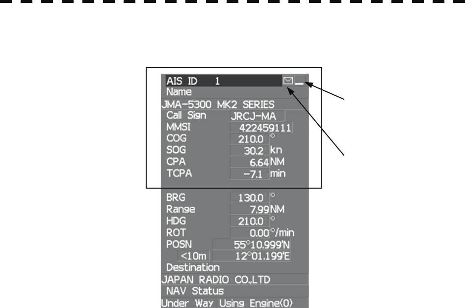
Digital information: AIS target information
①Detail / simple display
switching
Simple display item
②Unread message display
①:Detail / simple display switching
This function switches the display mode to detail / simple display when AIS target information is
displayed.
②:Unread message display
When there is an unread message from the AIS target that is displayed, the message is displayed. If this
button is clicked, the message is displayed.
2-25
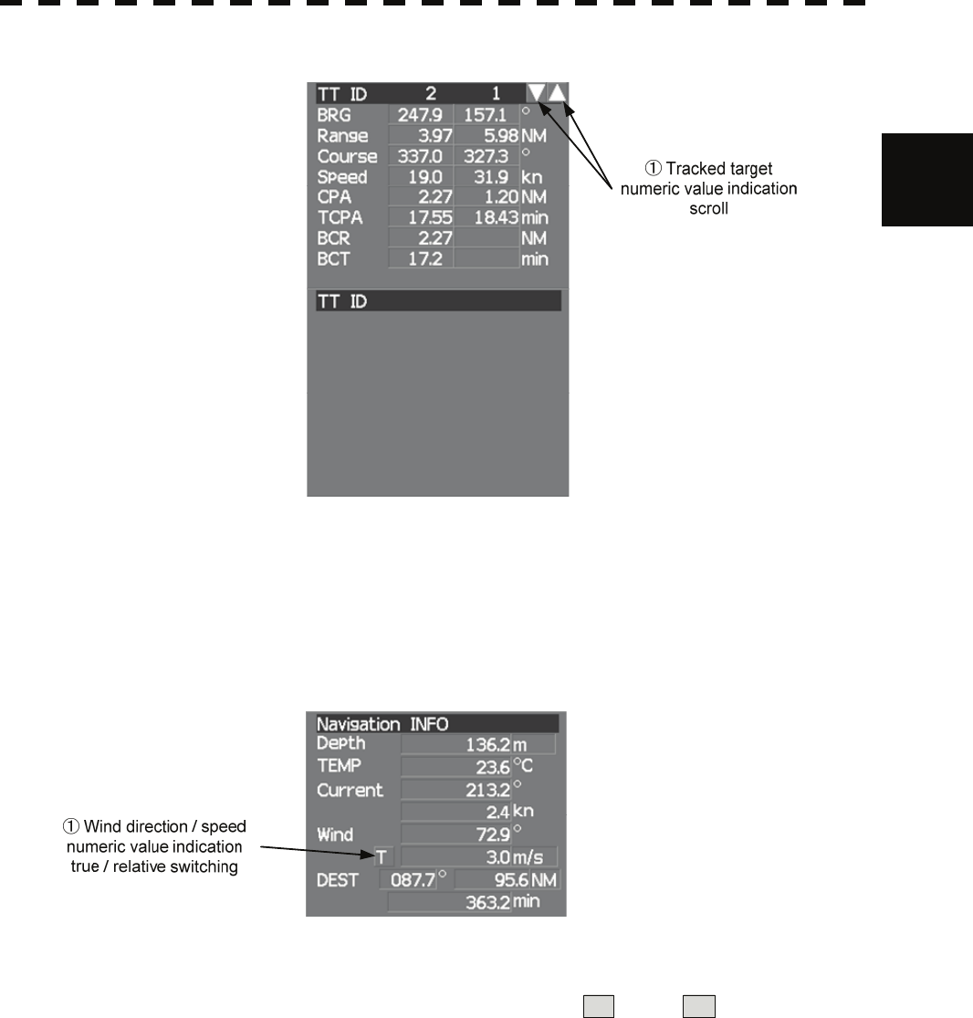
2.3 Functions of Software Buttons yy
Digital information: Tracked target information
2
①:Tracked target numeric value indication scroll
This function scrolls the target numbers that are indicated in the tracked target information.
Digital information: Navigation information
①:Wind direction / speed numeric value indication true / relative switching
The wind direction / speed numeric value indication is switched to T (true) / R (relative) whenever
this button is clicked.
2-26
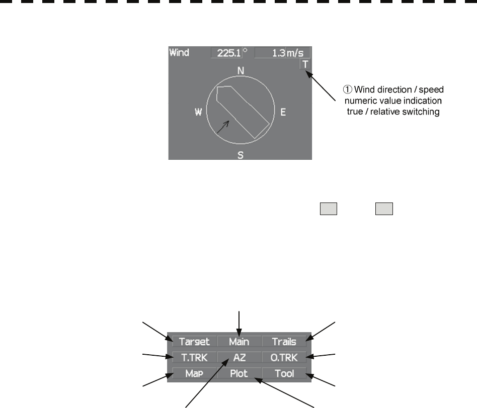
Digital information: Wind direction / speed
①:Wind direction / speed numeric value indication true / relative switching
The wind direction / speed numeric value indication is switched to T (true) / R (relative) whenever
this button is clicked.
Menu
① Digital information display
② Target ship’s track menu
③Map menu
⑦Radar trails menu
⑧Own ship's track menu
⑨Tool menu
⑤Automatic acquisition /
activation zone (AZ) menu
⑥Plotter menu
④Main menu
①:Digital information display
If this button is clicked while the menu screen is open, the menu is closed and control returns to the digital
information display.
This function switches between the tracked target / AIS target display and navigation information or the
course bar, and so on.
②:Target ship's track menu
If this button is clicked, the Target Track Setting menu is opened.
③:Map menu
If the button is clicked, the Map Setting menu is opened.
④:Main menu
If this button is clicked, the Main Menu is opened.
⑤:Automatic acquisition / activation zone (AZ) menu
If this button is clicked, the AZ Menu is opened.
2-27
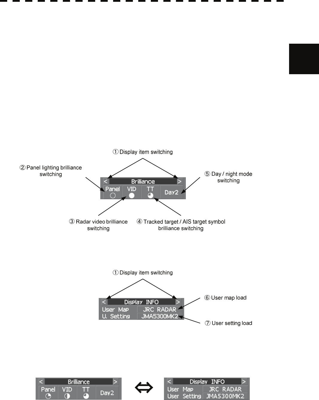
2.3 Functions of Software Buttons yy
⑥:Plotter menu
If this button is clicked, the Plot Menu is opened.
⑦:Radar trails menu 2
If this button is clicked, the RADAR Trails Setting menu is opened.
⑧:Own ship's track menu
If this button is clicked, the Own Track Menu is opened.
⑨:Tool menu
If this button is clicked, the Tool Menu is opened.
Brilliance
Display information
①:Display item switching
The brilliance adjustment screen and display information setting screen interchange whenever this button
is clicked.
2-28
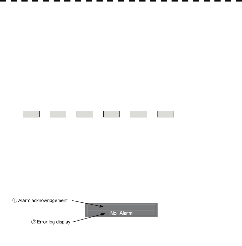
②:Panel lighting brilliance switching
This function enables the setting of the brilliance of the lighting of the control panel.
The brilliance changes whenever this button is clicked. Five levels of settings are available.
③:Radar video brilliance switching
Adjust the brightness of the radar video (echo).
The brilliance changes whenever this button is clicked. Four levels of settings are available.
④:Tracked target / AIS target symbol brilliance switching
Use this function to adjust the brilliance of the tracked target / AIS target symbol.
The brilliance changes whenever this button is clicked. Five levels of settings are available.
⑤:Day / night mode switching
The day / night mode is switched whenever this button is clicked.
Day1 ⇒ Day2 ⇒ Day3 ⇒ Dusk ⇒ Night ⇒ Day1
⑥:User map load
If this button is clicked, the user created map read menu is opened.
⑦:User setting load
If this button is clicked, the user setting read menu is opened.
Alarm
①:Alarm acknowledgment
If this button is clicked, the buzzer sound of the alarm that is currently issued is stopped and the alarm
lamp stops blinking. If multiple alarms are issued, the next alarm to be acknowledged is displayed.
If the button is clicked, the alarm displayed on the top is acknowledged.
The alarms that are currently issued are displayed at the bottom one by one.
②:Error log display
If this button is clicked, the error log is displayed.
2-29

SECTION 3
BASIC OPERATION
3.1 OPERATION FLOW................................................................................3-1
3.2 OBSERVE AND ADJUST VIDEO...........................................................3-5
3.3 OPERATION PROCEDURES...............................................................3-11
3.4 GENERAL RADAR OPERATION.........................................................3-21
3.5 USE OWN SHIP'S TRACK DATA.........................................................3-49
3.6 DISPLAY USER MAP ...........................................................................3-54
3.7 USE ROUTE FUNCTION......................................................................3-78
3.8 APPLIED OPERATIONS ......................................................................3-79
3.9 USE FUNCTION KEY [FUNC]..............................................................3-94
3.10 USE USER SETTING .........................................................................3-100
3.11 USING CARD......................................................................................3-102
3.12 DISPLAY SIMPLE CHART.................................................................3-108
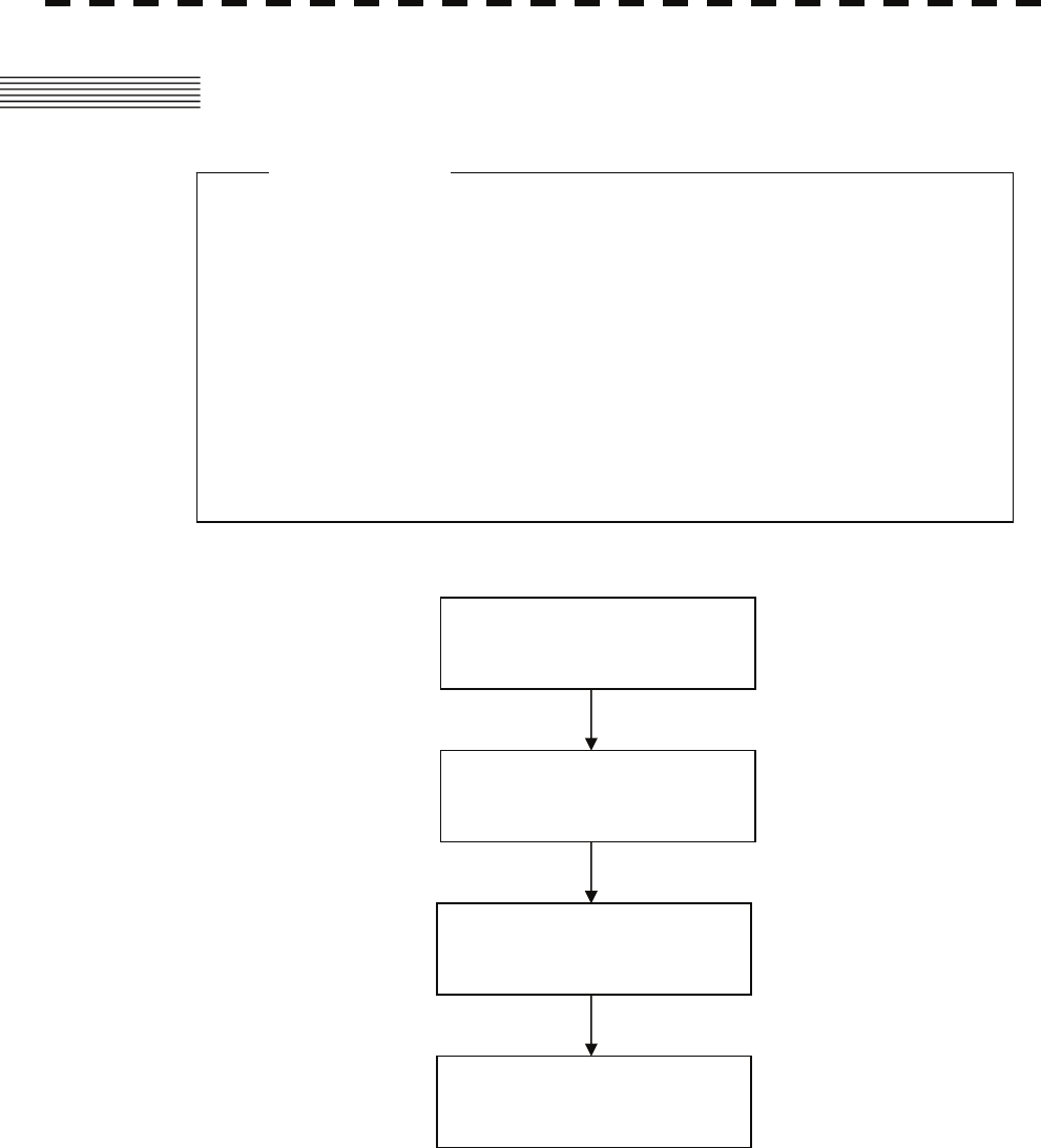
3.1 OPERATION FLOW
z Do not put anything on the operation panel.
If you put anything hot on it, it may be deformed.
z Do not give any impact to the operation panel,
trackball, or controls.
Otherwise, any failure or damage may result.
Attention
POWER ON AND
START THE SYSTEM
OBSERVE AND
ADJUST VIDEO
ACQUIRE AND
MEASURE DATA
END THE OPERATION AND
STOP THE SYSTEM
Each operation is described in detail below.
3-1
3
3.1 Operation Flow y
y y
3.1.1 Power ON and Start the System
CAUTION
z Wait for about 2 seconds before turning on the
power again.
Attention
A malfunction may occur if the power in the
ship is instantaneously interrupted during
operation of the radar. In this case, the power
should be turned on again.
z Immediately after the radar is installed, at start of the
system after it has not been used for a long time, or
after the magnetron is replaced, preheat the
equipment in the standby state for 20 to 30 minutes
before setting it into the transmit state.
z If the preheating time is short, the magnetron
causes sparks, resulting in its unstable oscillation.
Start transmission on a short-pulse range and
change the range to the longer pulse ranges in turn.
If the transmission is unstable in the meantime,
immediately place the system back into the standby
state and maintain it in the standby state for 5 to 10
minutes before restarting the operation.
Repeat these steps until the operation is stabilized.
3-2
Procedures 1 Check that the ship’s mains are turned on.
2 Press the [STBY] key.
The system is turned on, and the preheating time is displayed.
Preheat is indicated upper left of the display.
3 Wait until the preheating time is over.
When the preheating time is over, the preheating time screen disappears, and Preheat
upper left of the display changes to Standby .
4 Press the [TX / PRF] key.
The radar will start transmission and the antenna will start rotating.
Standby upper left of the display changes to Transmit .
Note: The radar does not start transmission if you Press the [TX / PRF] key while Preheat is
indicated.
3.1.2 Observe and Adjust Video
Procedures 1 Press the [RANGE+] key or [RANGE-] key to set the range to the scale
required for target observation.
2 Turn the dials [GAIN / PL], [AUTO-SEA], and [AUTO-RAIN] to obtain the
clearest targets.
Refer to
[GAIN/PL]→3-7P
[AUTO-SEA]→3-7P
[AUTO-RAIN]→3-9P
for how to use each dial.
For how to adjust video, see Chapter 3.2.
3.1.3 Acquire and Measure Data
For details on how to acquire data and measure, see Section 4 "Measurement of range and bearing."
3.1.4 Display and Measure with Reference to CCRP
The radar video, range, bearing, Target Tracking and AIS data display etc... are displayed with reference
to CCRP (Consistent Common Reference Point).
If scanner is switched, these data are measured from CCRP.
If some kind of functions set scanner position to outside of the PPI range, these data except Target
Tracking and AIS data are displayed with reference to scanner position.
For how to setting CCRP, see the section 7.1.9.
3-3
3
3.1 Operation Flow y
y y
3.1.5 End the Operation and Stop the System
Exit 1 Press the [STBY] key.
The radar will stop transmission and the antenna will stop rotating.
Transmit upper left of the display changes to Standby .
Maintain the standby state if radar observation is restarted in a relatively short time.
Only pressing the [TX / PRF] key starts observation.
2 Press the [STBY] key and the [TX / PRF] key together.
The system will be turned off.
WARNING
Some equipment components can carry electrical
current even after the power switch is turned off,
and conducting maintenance work without
unplugging the power connector may result in
electrocution, equipment failure, or accidents.
When conducting maintenance work, make sure
to turn off the power and unplug the power
connector J1 of the radar process unit so that the
power supply to the equipment is completely cut
off.
3-4

3.2 OBSERVE AND ADJUST VIDEO
3.2.1 Adjust Monitor Brilliance [BRILL]
Procedures 1 Obtain the best-to-see display with optimum brilliance by turning the
[BRILL] dial at the lower right of the LCD monitor.
Turning the [BRILL] dial clockwise increases the brilliance of the entire display.
Conversely, turning the [BRILL] dial counterclockwise decreases the brilliance of the
entire display.
In consideration of the ambient brightness, adjust display brilliance that is high enough to
easily observe the radar display but does not glare.
3.2.2 Change Observation Range [RANGE + / - ]
Procedures 1 When increasing the observation range, press the [RANGE+] key.
Increasing the observation range will enable a wider range to be observed.
However, a video image is small and the ability to detect targets near own ship decreases.
Therefore, when observing the vicinity of own ship, use the smaller observation range.
2 When decreasing the observation range, press the [RANGE-] key.
Decreasing the observation range will enable the vicinity of own ship to be enlarged.
However, caution must be taken because video images of the area beyond the observation
range cannot be displayed.
3-5
3
3.2 Observe and Adjust Video y
y y
3.2.3 Tune
CAUTION
Normally, use the automatic tune mode.
Use the manual tune mode only when best tuning
is not possible in the automatic tune mode due to
deterioration of magnetron.
This radar system provides the automatic tune mode and the manual tune mode. The automatic tune
mode automatically adjusts the tuning of the transmitting frequency and the receiving frequency, and the
manual tune mode enables tuning to be adjusted by using the dial located on the operation unit. The tune
mode currently being used is displayed in the tune mode switching (lower left of the display ⑫ on page
2-18).
When using the automatic tune mode
Procedures 1 Put the cursor on the tune mode switching (lower left of the display ⑫
on page 2-18) and press the [ENT] key.
The automatic tune mode is selected and AUTO is displayed in the tune mode field.
Tune adjustment is automatically conducted. Tune is adjusted at the start of transmission,
at the change of the range or pulse length. Tune adjustment is completed within several
seconds.
When using the manual tune mode
Procedures 1 Put the cursor on the tune mode switching (lower left of the display ⑫
on page 2-18) and press the [ENT] key to set the manual tune mode.
The automatic tune mode is cancelled, and MAN is displayed in the tune mode field.
2 Press the [MULTI] dial to set the ( Tune ) mode.
Tune is displayed in the multi-dial mode (lower left of the display on page 2-3).
3 Turn the [MULTI] dial to adjust tune.
Make adjustments so that the tuning indication (upper left of the display on page 2-2)
indicates the maximum.
3-6
3.2.4 Adjust Gain [GAIN / PL]
CAUTION
On the contrary, if the gain is too low, targets
including ships and dangerous objects may not
be clearly indicated.
If the gain is too high, unnecessary signals
including receiver noise and false video increase
resulting in reduction of visibility of targets.
Procedures 1 Adjust noise of the display by turning the [GAIN / PL] dial until targets
can be easily observed.
Turning [GAIN / PL] dial clockwise increases gain.
Turning [GAIN / PL] dial counterclockwise decreases gain.
By increasing receiving gain, the range to observe radar video is widened.
To observe densely crowded targets or short-range targets, reducing the receiving gain will
enable the targets to be easily observed.
3-7
3
3.2 Observe and Adjust Video y
y y
3.2.5 Suppress Sea Clutter [AUTO-SEA]
CAUTION
When using the sea clutter suppression function,
never set the suppression level too high
canceling out all image noises from the sea
surface at close range.
Detection of not only echoes from waves but also
targets such as other ships or dangerous objects
will become inhibited.
When using the sea clutter suppression function,
make sure to choose the most appropriate image
noise suppression level.
Using the manual sea clutter suppression mode
Procedures 1 Adjust the sea clutter returns of the display by turning the [AUTO-SEA]
dial until targets can be easily observed.
Turning [AUTO-SEA] dial clockwise suppresses sea clutter returns.
Turning [AUTO-SEA] dial counterclockwise intensifies sea clutter returns.
The sea clutter suppression function suppresses sea clutter returns by decreasing the receiving
gain on a short range.
Turning the [AUTO-SEA] dial clockwise heightens the effect of sea clutter suppression.
However, be careful that excessive suppression causes low signal-strength targets such as
buoys and boats to disappear from the radar display.
3-8
Using the automatic sea clutter suppression mode
The sea clutter suppression in accordance with the intensity of sea clutter is possible. Use this
mode when the sea clutter's intensity differs according to directional orientation.
Procedures 1 Press the [AUTO-SEA] dial.
The automatic sea clutter suppression mode is selected, and AUTO is displayed in sea
clutter suppression (Sea) mode switching (lower left of the display ⑩ on page 2-18).
2 Make adjustments by turning the [AUTO-SEA] dial.
Even when the automatic sea clutter suppression mode is selected, turning the
[AUTO-SEA] dial can make fine adjustments manually.
Note: When the automatic sea clutter suppression mode is selected, the automatic rain/snow
suppression mode is switched to the manual mode.
To select both the sea clutter suppression function and the rain/snow suppression function in the
automatic mode, use the automatic rain/snow suppression mode.
Cancellation 1 Press the [AUTO-SEA] dial.
The automatic sea clutter suppression mode is cancelled, and MAN is displayed in the
sea clutter suppression (Sea) mode field.
3.2.6 Suppress Rain / Snow Clutter [AUTO-RAIN]
CAUTION
When using the rain clutter suppression function,
make sure to choose the most appropriate image
noise suppression level.
When using the rain clutter suppression function,
never set the suppression level too high
canceling out all image noises from the rain or
snow at the close range.
Detection of not only echoes from the rain or
snow but also targets such as other ships or
dangerous objects will become inhibited.
3-9

3
3.2 Observe and Adjust Video y
y y
Using the manual rain / snow clutter suppression mode
Procedures 1 Adjust the rain / snow clutter returns of the display by turning the
[AUTO-RAIN] dial until targets can be easily observed.
Turning [AUTO-RAIN] dial clockwise suppresses rain / snow clutter returns.
Turning [AUTO-RAIN] dial counterclockwise intensifies rain / snow clutter returns.
When the [AUTO-RAIN] dial is turned clockwise, the rain / snow clutter suppression function
suppresses rain / snow clutter returns and gets targets hidden by rain / snow clutter returns to
appear of the display. However, be careful that excessive suppression may cause small targets
to be overlooked. Since the rain / snow clutter suppression function also has the effect of
suppressing sea clutter, the suppression efficiency improves when the [AUTO-RAIN] dial is
used with the [AUTO-SEA] dial. In general, turn the [AUTO-RAIN] dial fully to the left.
Using the automatic rain / snow clutter suppression mode
The rain / snow clutter suppression in accordance with the intensity of rain / snow clutter is
possible. Use this mode when the rain / snow clutter's intensity differs according to directional
orientation.
Procedures 1 Press the [AUTO-RAIN] dial.
The automatic rain / snow clutter suppression mode is selected, and AUTO is
displayed in the sea clutter suppression (Sea) mode switching and the rain / snow clutter
suppression (Rain) mode switching ( lower left on the display ⑩ and ⑪ on page 2-18)
2 Make adjustments by turning the [AUTO-RAIN] dial and the [AUTO-SEA]
dial.
Even when the automatic rain / snow clutter suppression mode is selected, turning the
[AUTO-RAIN] dial and the [AUTO-SEA] dial can make fine adjustments manually.
Note: When the automatic rain / snow clutter suppression mode is selected, the automatic sea clutter
suppression mode is also activated.
It is not possible to set only the rain / snow clutter suppression function to the automatic mode.
Cancellation 1 Press the [RAIN] dial.
The automatic rain / snow clutter suppression mode is cancelled, and AUTO is
changed to MAN in the sea clutter suppression (Sea) mode field and the rain / snow
clutter suppression (Rain) mode field.
3.2.7 Reset Alarm Buzzer [ALARM ACK]
When an audible alarm is issued, use [ALARM ACK] to acknowledge the alarm information, stop the
alarm buzzing, and stop the alarm lamp flashing. (If more than one alarm has occurred, press the key for
each alarm indication.) The alarm stops buzzing, but the alarm indication does not disappear.
Procedures 1 Press the [ALARM ACK] key.
The alarm will stop buzzing.
3-10

3.3 OPERATION PROCEDURES
3.3.1 Move Cross Cursor Mark by Trackball
The cross cursor mark + is used for position designation and other purposes in various operating
procedures. The cross cursor mark + moves in coupling with the trackball. If the trackball is rotated
up and down or right and left, the cross cursor mark follows the move of the trackball.
Operators must be familiar with trackball operation before running the system.
Operation inside Radar Video PPI
The cross cursor mark as shown at right is displayed inside the radar video PPI.
1) The distance, bearing, and latitude / longitude are digitally indicated in the cursor bearing, range,
latitude, and longitude (upper right of the display on page 2-3).
2) When moving the current center position, use the cross cursor mark to designate a new center
position.
3) Use the cross cursor mark to create marks and lines.
4) Use the cross cursor mark to designate a target in the target tracking (TT) function and the AIS
display function.
5) Use the cross cursor mark to adjust EBL, VRM, automatic acquisition and activation zone (AZ),
radar alarm zone (RA), parallel index line (PI), and AIS filter.
Operation outside Radar Video PPI
As shown at right, the cursor mark changes into the cursor outside the radar video PPI.
1) Use the cursor to operate software buttons.
2) Use the cursor to select menu items.
* The EBL / VRM dial is available for operating the cursor mark. Pressing the EBL dial for 2 seconds
can perform switching to the trackball operation. For details, refer to Section 3.8.4.
3-11
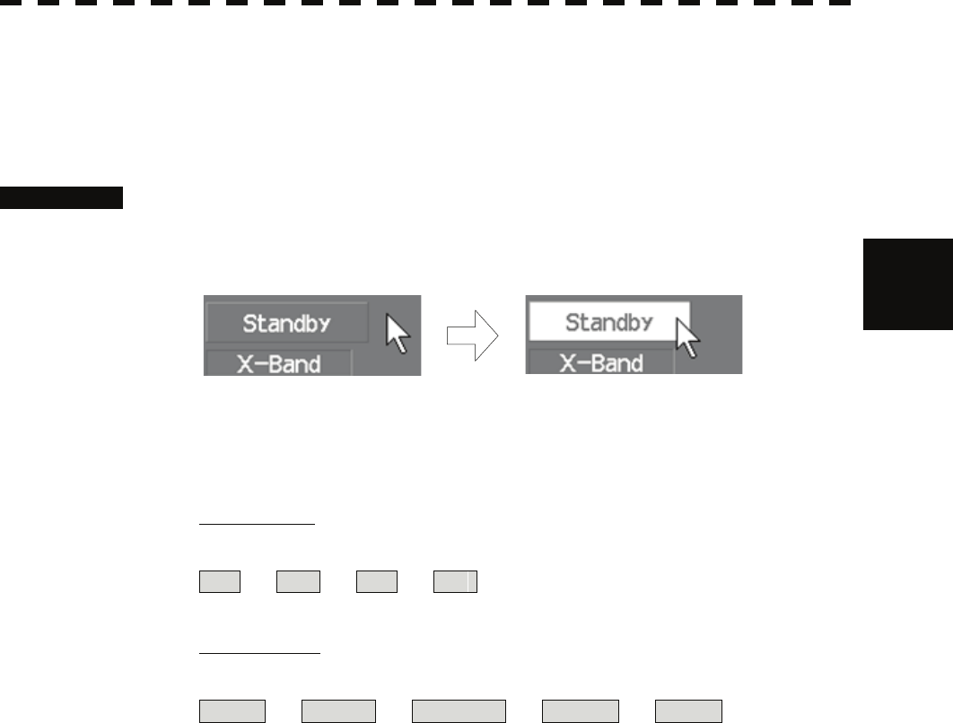
3
3.3 Operation Procedures y
y y
3.3.2 Operate Software Buttons
Software buttons are provided of the display so as to easily switch functions without operating menu
items.
For software buttons that can be operated and their locations, see Chapter 2.
Procedures 1 Put the pointer on the software button of the display.
The software button indicated by the cursor will be shown in reverse video, which
indicates that the button is specified.
2 Press the [ENT] key.
The operating state changes according to the function of the software button.
On / off settings
Each time the [ENT] key is pressed, the operating state switches as follows:
On ⇒ Off ⇒ On ⇒ Off
Multiple settings
For example, each time the [ENT] key is pressed, the operating state switches as follows:
IR Off ⇒ IR Low ⇒ IR Middle ⇒ IR High ⇒ IR Off
3-12

3.3.3 Basic Menu Operation
To open the menu:
Put the cursor on main menu Main (Menu ④ on page 2-27) and press the [ENT] key, and the
main menu will open. Alternatively, press the [RADAR MENU] key.
By putting the cursor on Target , Map , or AZ adjacent to Main and pressing the [ENT]
key, the menu exclusive for the function will open.
For the arrangement of software buttons, see Chapter 2.
To close the menu:
Put the cursor on digital information display Target (Menu ① on page 2-27) and press the
[ENT] key, and the menu will close and the digital information display screen will appear.
Alternatively, press the [0] key until the menu will close.
To move to a lower level of the menu:
The menu is in hierarchical structure. Put the cursor on the desired menu item and press the [ENT]
key, and control will move to the lower level. Alternatively, Press numeric keys corresponding to the
desired menu item number, and the > mark will appear at the right end of a menu item having a
lower level.
To move to a higher level of the menu:
Put the cursor on 0. Exit located lower of the menu when the menu is open. Control will return to
the higher level. Alternatively, press the [0] key.
To determine an item:
Put the cursor on the menu item you want to change and press the [ENT] key. The selected item will
be displayed. Alternatively, Press numeric keys corresponding to the desired item number.
To determine the selected item:
Put the cursor on the desired item and then press the [ENT] key. The selected item will be determined.
Alternatively, Press numeric keys corresponding to the selected item number.
If you do not change the setting of the selected item, press the [CLR / INFO] key. The selected item
will be closed without changing the settings.
3-13
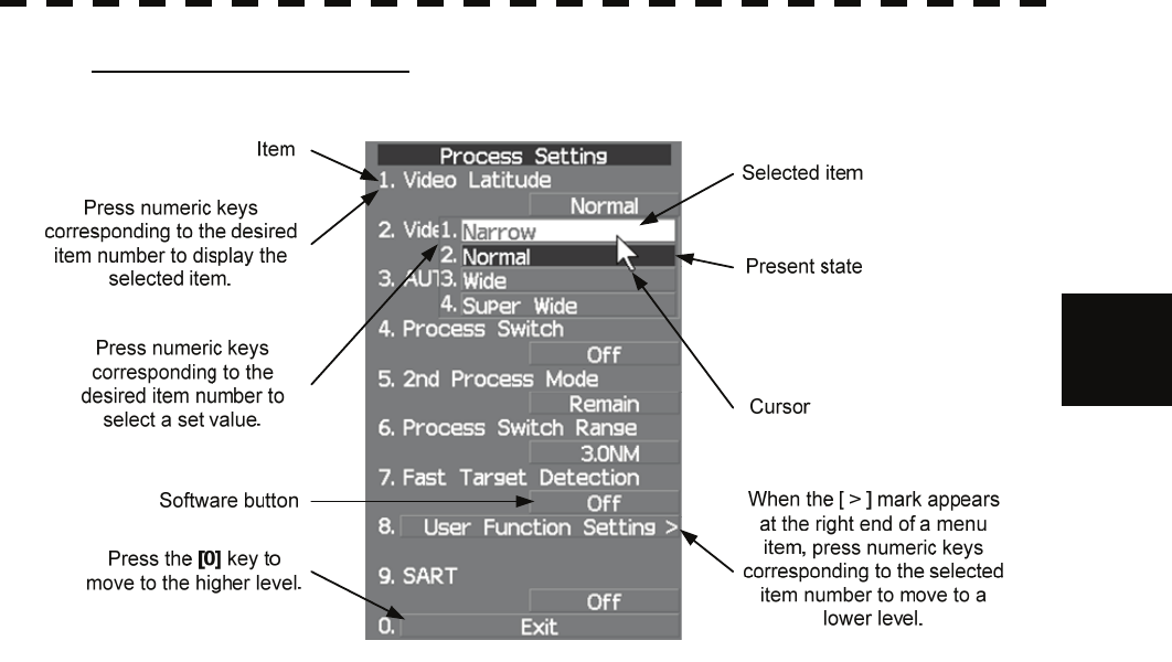
3
3.3 Operation Procedures y
y y
Example of menu display
3-14
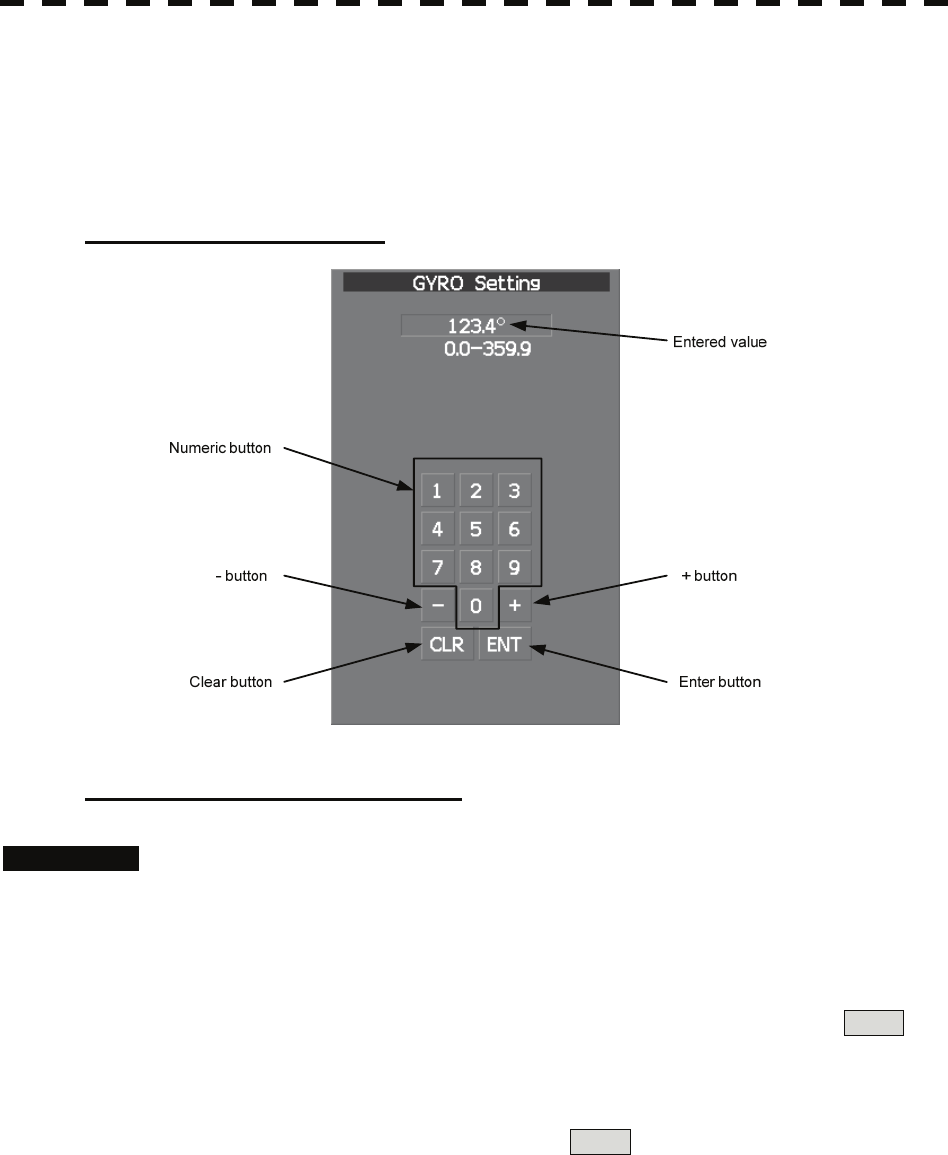
3.3.4 Operation on Numeric Value, Latitude / Longitude and
Character Input menu
When a numeric value, latitude / longitude, or character must be entered during operation, the input
screen will appear. Enter a numeric value, latitude / longitude, or character according to the procedures
below.
Numeric value input menu
Directly entering a numeric value
Procedures 1 On the numeric value input menu, sequentially press numeric keys to
enter a desired numeric value.
For example, when entering 123.4° for a bearing value, sequentially press the keys as
follows:
[1] →[2] →[3] →[4]
2 Make sure that the entered value is correct, put the cursor on ENT ,
and then press the [ENT] key.
The set value is reflected to the operating state.
3 To cancel input, put the cursor on CLR , and then press the [ENT] key.
The numeric value input menu will close without reflecting the set value to the operating
state.
3-15
3
3.3 Operation Procedures y
y y
Increasing or decreasing a numeric value
Procedures 1 On the numeric value input menu, put the cursor on + or - , and
then press the [ENT] key to increase or decrease numeric value so as to
change to the desired numeric value.
For example, to change bearing value of 123.0° to 123.4°, put the cursor sequentially on
+ located on the software numeric value input menu, and then press the [ENT] key
four times.
* Turning the [MULTI] dial will conduct the same operation.
2 Make sure that the entered value is correct, put the cursor on ENT ,
and then press the [ENT] key.
The set value is reflected to the operating state.
3 To cancel input, put the cursor on CLR , and then press the [ENT] key.
The numeric value input menu will close without reflecting the set value to the operating
state.
3-16
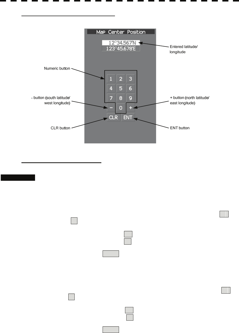
Latitude / longitude input screen
Entering latitude / longitude
Procedures 1 On the latitude / longitude input menu, sequentially press numeric keys
to enter latitude (XX°XX.XXX').
For example, to enter 12°34.567', sequentially press numeric keys as follows.
[1] →[2] →[3] →[4] →[5] →[6] →[7]
2 To make change between north latitude and south latitude, use +
and - .
North latitude: Put the cursor on + and then press the [ENT] key.
South latitude: Put the cursor on - and then press the [ENT] key.
3 Put the cursor on ENT and then press the [ENT] key.
The manually entered latitude value is determined. Then, enter the longitude value.
4 Sequentially press numeric keys to enter longitude (XXX°XX.XXX').
5 To make change between east longitude and west longitude, use +
and - .
East longitude: Put the cursor on + and then press the [ENT] key.
West longitude: Put the cursor on - and then press the [ENT] key.
6 Put the cursor on ENT and then press the [ENT] key.
The manually entered longitude value is determined.
3-17
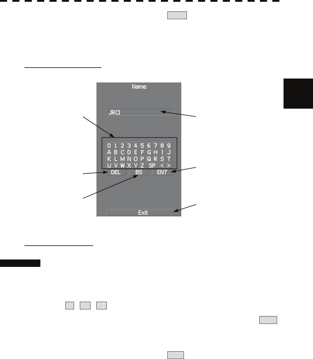
3
3.3 Operation Procedures y
y y
7 To cancel input, put the cursor on CLR and then press the [ENT] key.
The latitude / longitude input menu will close without reflecting the set value to the
operating state.
Character input screen
Enter button
Back Space button
Delete button
Character/Number button Entered character
Exit button
Entering a character
Procedures 1 On the character input menu, use trackball to select alphabet from A to Z,
numbers from 0 to 9, or symbols (only comments for mark / line), and
then press the [ENT] key to enter one character of the name to be
inputted.
For example, JRC for a name, click button as follows:
J → R → C
2 Make sure that the entered character is correct, put the cursor on ENT ,
and then press the [ENT] key.
The character has been entered.
3 To cancel input, put the cursor on Exit , and press the [ENT] key.
The character input menu will be closed without entering the character.
3-18

3.3.5 Overview of Menu Structure
The menu structure of this radar system consists of seven frequently used function menus, one main
menu, and one service man menu used for the installation settings.
Software buttons for opening those menus are displayed in the menu area.
For each menu item and structure, see the menu list in the appendix.
To prevent incorrect use, enter the special code to open the service man menu. For operating the service
man menu, see Chapter 7.
Frequently used functions
Trails Used for operating and setting the radar trails function.
T.TRK Used for operating and setting the target track function.
AZ Used for operating and setting the automatic acquisition / activation function.
O.TRK Used for operating and setting the own ship track function.
Map Used for operating and setting the map function.
Plot Used for operating and setting the plotter function.
Tool Used for operating and setting the navigation tool functions.
Main menu
Main Used for operating and setting the functions other than the above.
Service man menu
This menu is used for operation and settings when a system is installed.
It is not used during normal operation.
The special code must be entered to open the service man menu.
3.3.6 Operate Multi-Dial [MULTI]
The [MULTI] dial is provided to change the settings of parameters such as the length of radar trails.
Radar operation is simplified by using the [MULTI] dial.
[I] Initial Setting (Multi Dial Setting)
Set parameters that can be operated with the multi-dial.
Procedures 1 Press the [MULTI] dial for 2 seconds.
The Multi Dial Setting menu will appear.
3-19
3
3.3 Operation Procedures y
y y
2 Press numeric keys corresponding to the desired item number.
On and off functions of the item are switched.
On : Operation is conducted by the [MULTI] dial.
Off : Operation is not conducted by the [MULTI] dial.
Items set to On can be opened by pressing the [MULTI] dial.
Item overview
Vector Length : The vector length of tracked target and activate AIS target is
adjusted.
Trails Length : The radar trails length is adjusted.
TT Display No. : The target numbers of tracked target to be displayed are
switched.
C-Up Angle : The course in the course up mode is adjusted.
Mark/Line Color : Mark / line colors are switched.
Manual Tune : Tune in the manual tune mode is adjusted.
[II] Using Multi-dial
Procedures 1 Press the [MULTI] dial to select the parameter whose setting is to be
changed.
The multi-dial modes are switched.
Vector ⇒ Trails ⇒ TGT No. ⇒ Course ⇒ Mark ⇒
⇒ Tune ⇒ Vector
The selected item is displayed in the multi-dial mode (lower left of the display on page
2-3).
For example, when three items, 1/2/3, are set to On at the initial setting, the multi-dial
modes switch as shown below every time the [MULTI] dial is pressed.
Vector ⇒ Trails ⇒ TGT No. ⇒ Vector
2 Turn the [MULTI] dial to change the setting.
The preset values of the selected parameter will change sequentially.
Stop turning the dial when the desired value appears.
3-20
3.4 GENERAL RADAR OPERATION
3.4.1 Interference Rejection (IR)
Interference by other radars is rejected.
z When viewing a radar beacon or SART signal, select
IR Off (Interference Rejection Off) because IR
processing suppresses the video.
Attention
Procedures 1 Put the cursor on interference rejection (IR) mode switching IR ( ②
lower left of the display on page 2-18) and press the [ENT] key.
The interference rejection modes are switched.
IR Off ⇒ IR Low ⇒ IR Middle ⇒ IR High ⇒ IR Off
Rejection levels of the interference rejection
IR Off : Interference rejection off
IR Low : Interference rejection level - low
IR Middle : Interference rejection level - middle
IR High : Interference rejection level - high
When a high interference rejection level is selected, the radar’s ability of detecting small
targets such as buoys and small boats lowers.
In general, IR Low should be selected.
3-21
3
3.4 General Radar Operation y
y y
3.4.2 Switch Transmitter Pulse Length [GAIN / PL]
Procedures 1 Press the [GAIN / PL] dial.
Values of the transmitter pulse length are switched.
Example MP1 ⇒ MP2 ⇒ LP1 ⇒ LP2 ⇒ MP1
Effects of transmitter pulse length
With SP selected:
The transmitter pulse becomes shorter, and the range resolution improves.
The effect of suppressing sea clutter returns and rain / snow clutter returns heightens.
Recommended condition for selection:
In bays / harbors where targets are densely crowded
Rough sea state due to torrential rain or stormy weather
With MP selected:
The normal transmitter pulse length is set.
Both range resolution and gain are appropriately set.
Recommended condition for selection:
General navigation
With LP selected:
The transmitter pulse becomes longer, and gain improves.
Small targets are zoomed and are easy to observe.
When the sea state is bad, detection performance decreases.
Recommended condition for selection:
Detection of small targets in good weather conditions
Usable transmitter pulse length differs according to the type of scanner unit being used and the
observation range being used. For usable pulse length, see Chapter 11.
3-22
3.4.3 Target Enhance (ENH)
The dimension of video display is enlarged to enhance a target.
Procedures 1 Put the cursor on target enlarge (ENH) mode switching ENH (lower
left of the display ③ on page 2-18) and press the [ENT] key.
The target enlargement levels are switched.
ENH Off ⇒ ENH Level1 ⇒ ENH Level2 ⇒ ENH Level3 ⇒
⇒ ENH Off
Effect of target enlargement
ENH Off Enhance off : Select this mode particularly when resolution is required.
ENH Level1 Enhance - small : Select this mode in general.
Radar echoes are expanded by 1 scale in all directions.
ENH Level2 Enhance - medium : Select this mode to easily view the radar video.
Radar echoes are expanded by 2 scales in all directions on
the display.
ENH Level3 Enhance - large : Select this mode to detect small targets such as buoys.
The expansion near a screen center is added to ENH Level2.
Note: When ENH Level3 is selected, sea clutter returns and rain / snow clutter returns are apt to be
expanded. When using this expansion mode, operate [AUTO-SEA] dial and
[AUTO-RAIN] dial to suppress sea clutter returns and rain / snow clutter returns.
In general, ENH Level1 or ENH Level2 should be selected.
3-23
3
3.4 General Radar Operation y
y y
3.4.4 Use Video Processing (PROC)
This function reduces unnecessary noise to highlight targets.
z When viewing a radar beacon, SART signal, or fast
moving target on the radar display, select PROC Off
(video processing off).
z If video processing mode is set to CORREL , it may
be difficult to detect high speed target.
Procedures 1 Put the cursor on radar video processing (PROC) mode switching
PROC (lower left of the display ④ on page 2-18) and press the [ENT]
key.
The video processing modes are switched.
PROC Off ⇒ 3Scan CORREL ⇒ 4Scan CORREL ⇒ 5Scan CORREL
⇒ Remain ⇒ Peak Hold ⇒ PROC Off
Video process modes
PROC Off : Select this mode in general.
3Scan CORREL : Select this mode when many rain / snow clutter returns are detected.
4Scan CORREL : Select this mode to highlight targets while suppressing sea clutter returns.
5Scan CORREL : Select this mode to detect small targets hidden by sea clutter returns.
Remain : Select this mode when own ship yaws wildly.
Peak Hold : Select this mode to detect small targets of which detection probability is low.
Attention
3-24