Japan Radio NKE249 Marine Radar User Manual JMA2343 and JMA2344 Manual 1 of 4
Japan Radio Co Ltd. Marine Radar JMA2343 and JMA2344 Manual 1 of 4
Contents
- 1. JMA2343 and JMA2344 Manual 1 of 4
- 2. JMA2343 and JMA2344 Manual 2 of 4
- 3. JMA2343 and JMA2344 Manual 3 of 4
- 4. JMA2343 and JMA2344 Manual 4 of 4
JMA2343 and JMA2344 Manual 1 of 4
![JJMMAA-- 22334433 22334444 IINNSSTTRRUUCCTTIIOONN MMAANNUUAALL [English edition]](https://usermanual.wiki/Japan-Radio/NKE249.JMA2343-and-JMA2344-Manual-1-of-4/User-Guide-288864-Page-16.png)
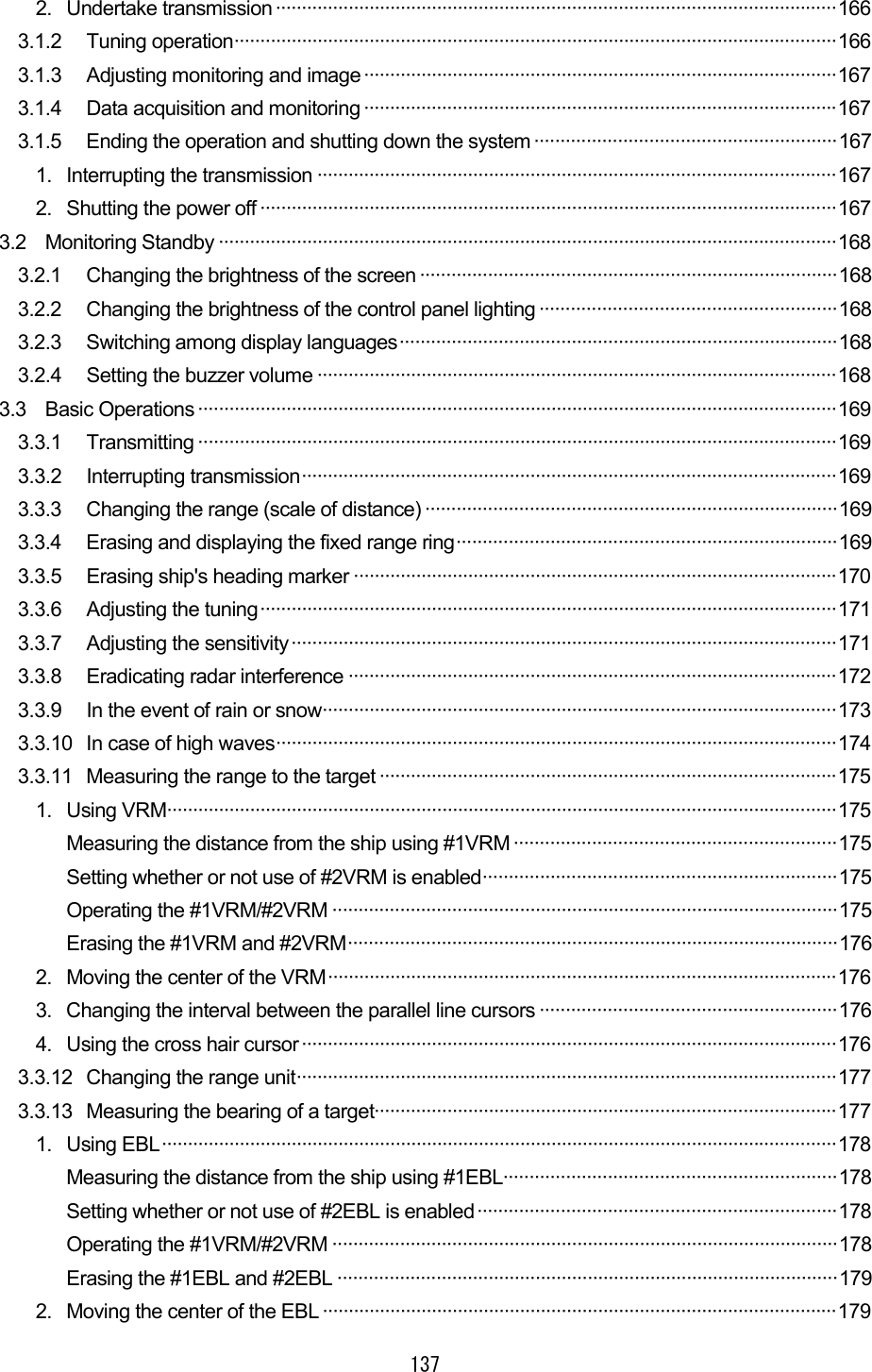
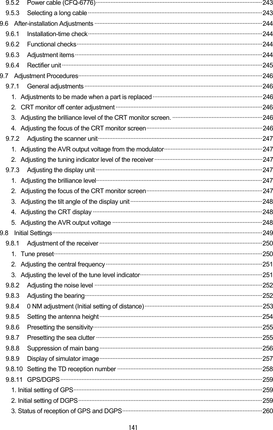
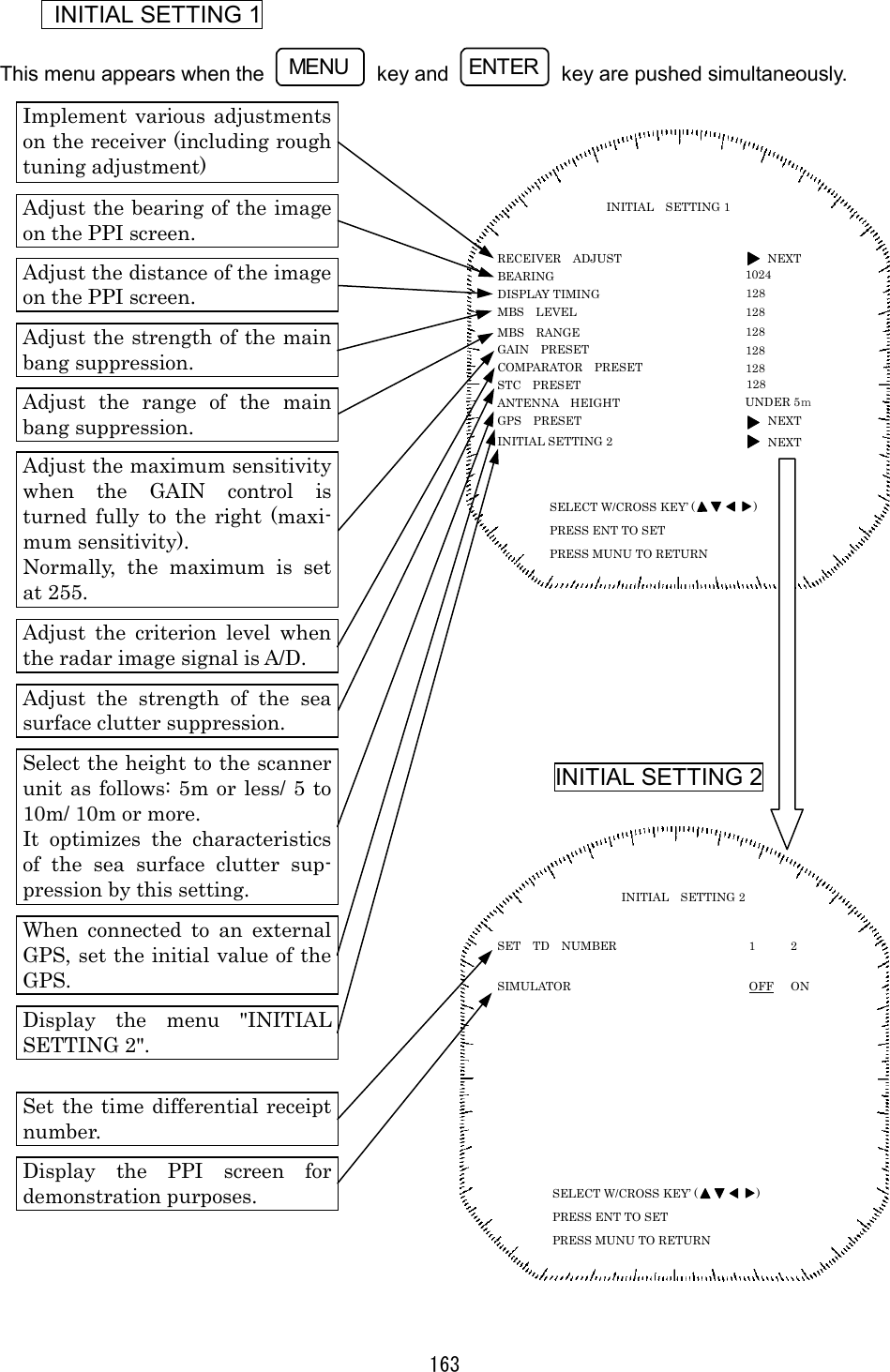
![159 Initial Setting Menu SELECT W/CROSS KEY’ ( ) SELECT W/CROSS KEY’ ( ) SELECT W/CROSS KEY’ ( ) SELECT W/CROSS KEY ( ) SELECT W/CROSS KEY’ ( ) ++++Push those keys simultaneously. MENUMENUMENUMENU ENTERENTERENTERENTER CONDITION DOP: VERSION: ALITUDE: RSSI[BEACON]: DATE/TIME:21 JAN 2002 SAT NO. ELV. AZIMUTH SNR (UTC) 11:14 GPS DGPS PRESET MODE FREQUENCY BAUD RATE SEND DATA MANUAL AUTO 200.0kHz 50 100 200 GPS PRESET GPS NEXT CONDITION NEXT DGPS NEXT INITIAL SETTING 2 SIMULATOR OFF ON INITIAL SETTING 1 RECEIVER ADJUST NEXT DISPLAY TIMING MBS LEVEL COMPARATOR PRESET STC PRESET ANTENNA HEIGHT 1024 128 128 128 128 UNDER 5m BEARING MBS RANGE 128 GAIN PRESET 128 GPS PRESET NEXT INITIAL SETTING 2 NEXT GPS POSITION ANTENNA HEIGHT GEODETIC FIX MODE DOP LEVEL POSN AVARAGE EXCUSION SAT. SEND DATA N 35°00.00 15 2D 3D FIX 43 UP TO 5 UP TO 10 UP TO 20 LONG STANDARD NONE W 135°00.00 00 01 02 03 04 05 SET TD NUMBER 1 2 MOTOR ON OFF TUNE FREQUENCY 50 TUNE PRESET 128 TUNE LEVEL IND. 50 PRESS MUNU TO RETURN PRESS ENT TO SET PRESS MUNU TO RETURN PRESS ENT TO SET PRESS MUNU TO RETURN PRESS CROSS KEY ( ) PRESS MUNU TO RETURN PRESS ENT TO SET PRESS MUNU TO RETURN PRESS ENT TO SET SAT NO. ELV. AZIMUTH SNR SAT NO. ELV. AZIMUTH SNR](https://usermanual.wiki/Japan-Radio/NKE249.JMA2343-and-JMA2344-Manual-1-of-4/User-Guide-288864-Page-40.png)
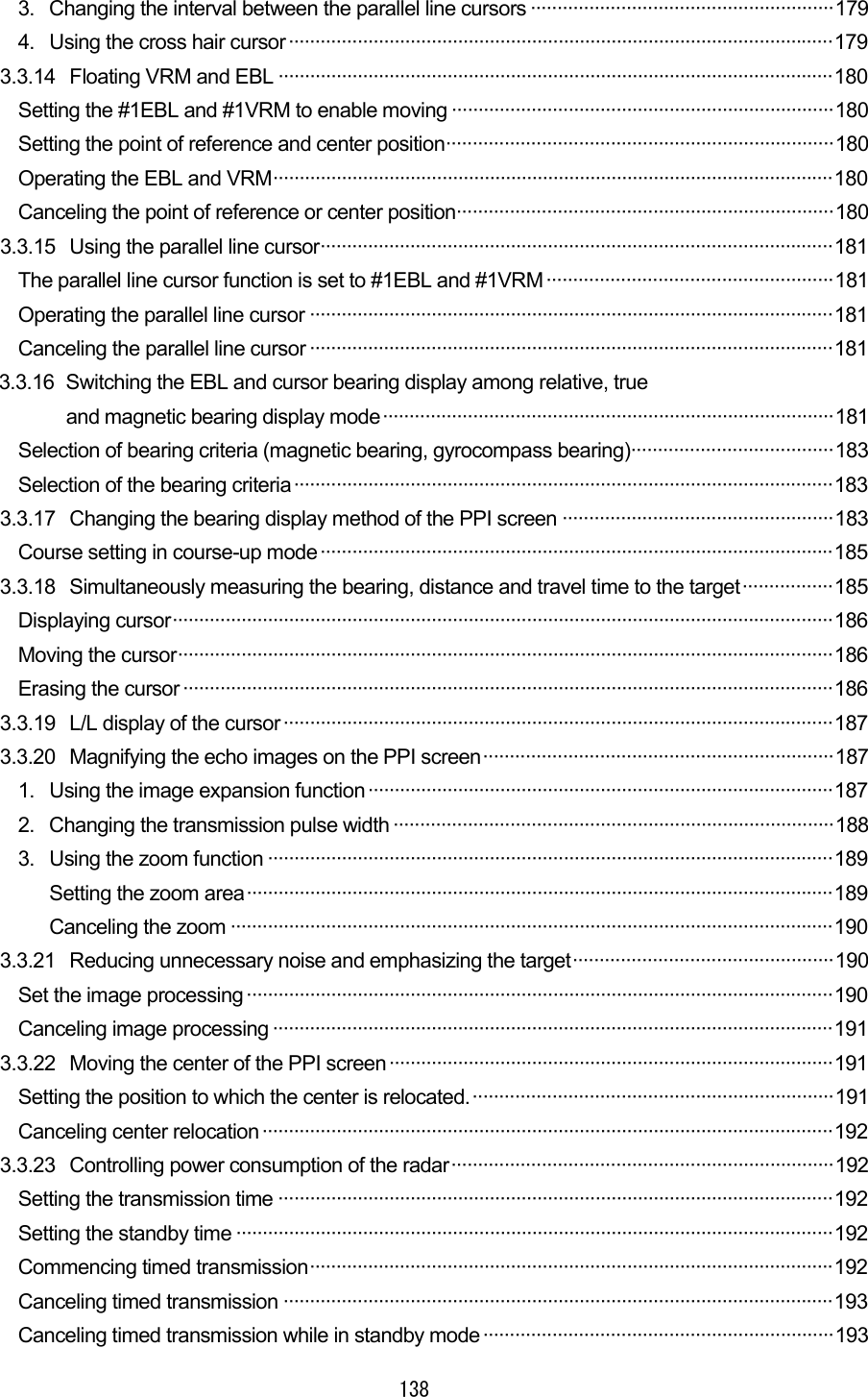
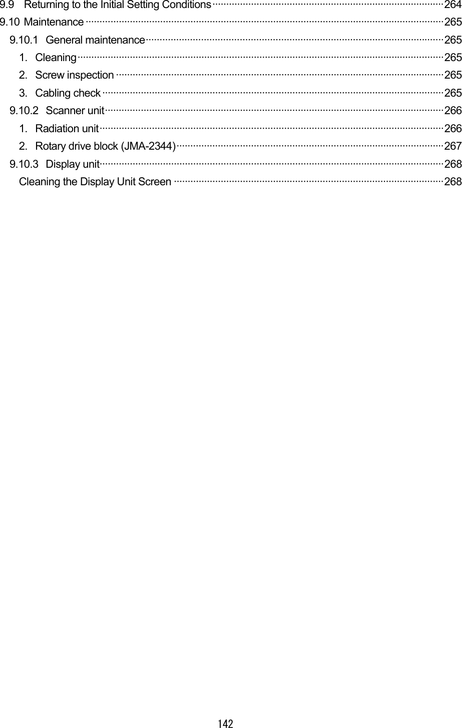
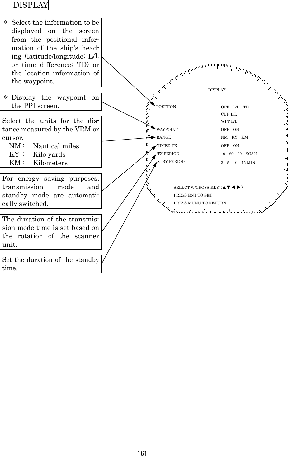
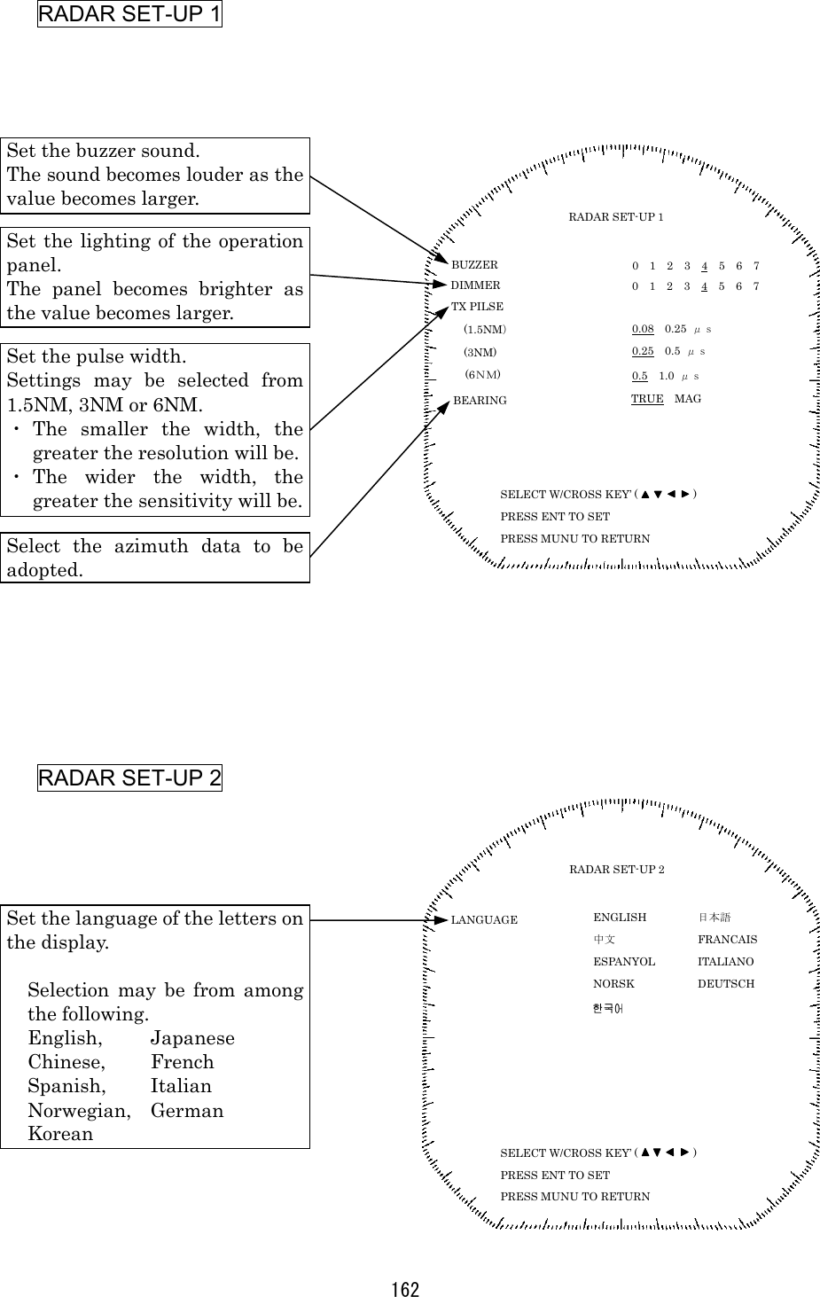
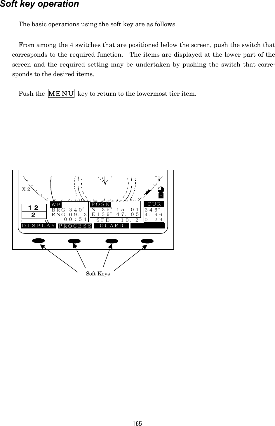
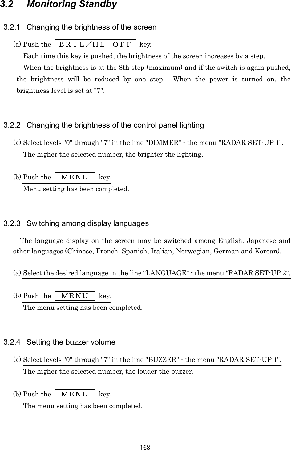
![160 2.3.2 Functions within the menu When using functions marked with [*], connectivity to an external navigation system is required. FUNCTION Select the operating functionof EBL1 and VRM1. Select use of EBL2. Select use of VRM2. Display any random portion ofthe PPI image enlarged totwice the original image. Select read for the azimuthvalue of EBL. * Select "relative" or "true"motion display. * Select the method of dis-playing the bearing of thePPI screen. Select the correlative process-ing of the radar echo. FUNCTION EBL1/EBL2 EBL2 VRM2 EBL READOUT ZOOM TM/RM HDG MODE PROCESS FIX FLOAT PLINE1 PLINE2 NO YES NO YES REL TRUE,MAG OFF SET RM TM H-UP N-UP C-UP OFF PR1 PR2 SELECT W/CROSS KEY’ ( ) PRESS ENT TO SET PRESS MUNU TO RETURN](https://usermanual.wiki/Japan-Radio/NKE249.JMA2343-and-JMA2344-Manual-1-of-4/User-Guide-288864-Page-41.png)
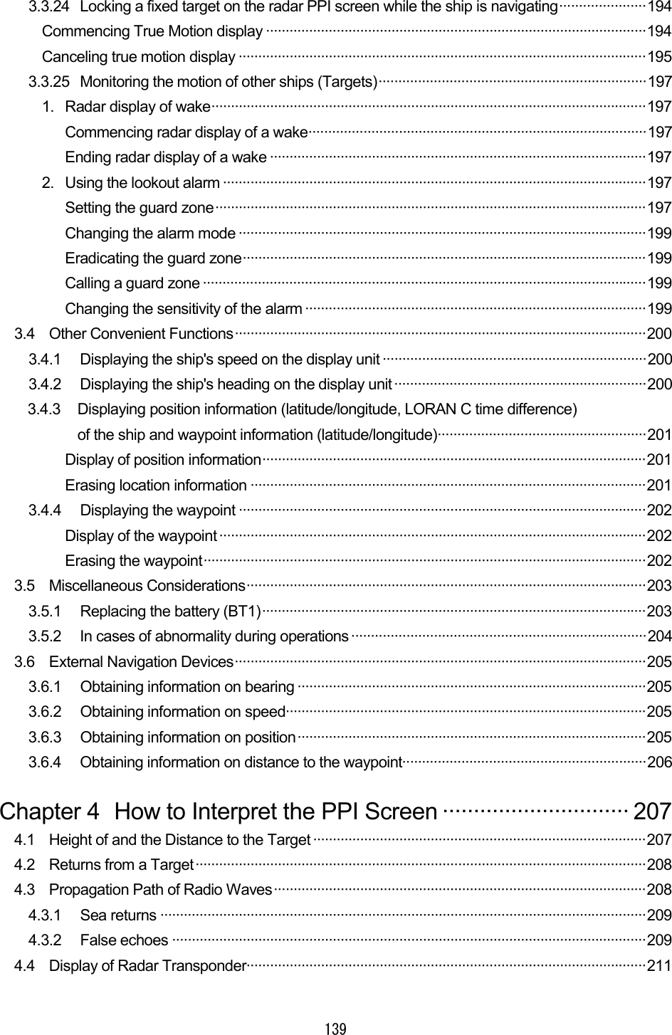
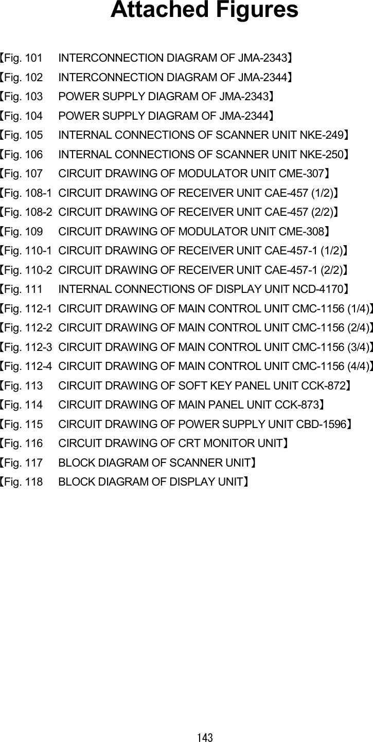
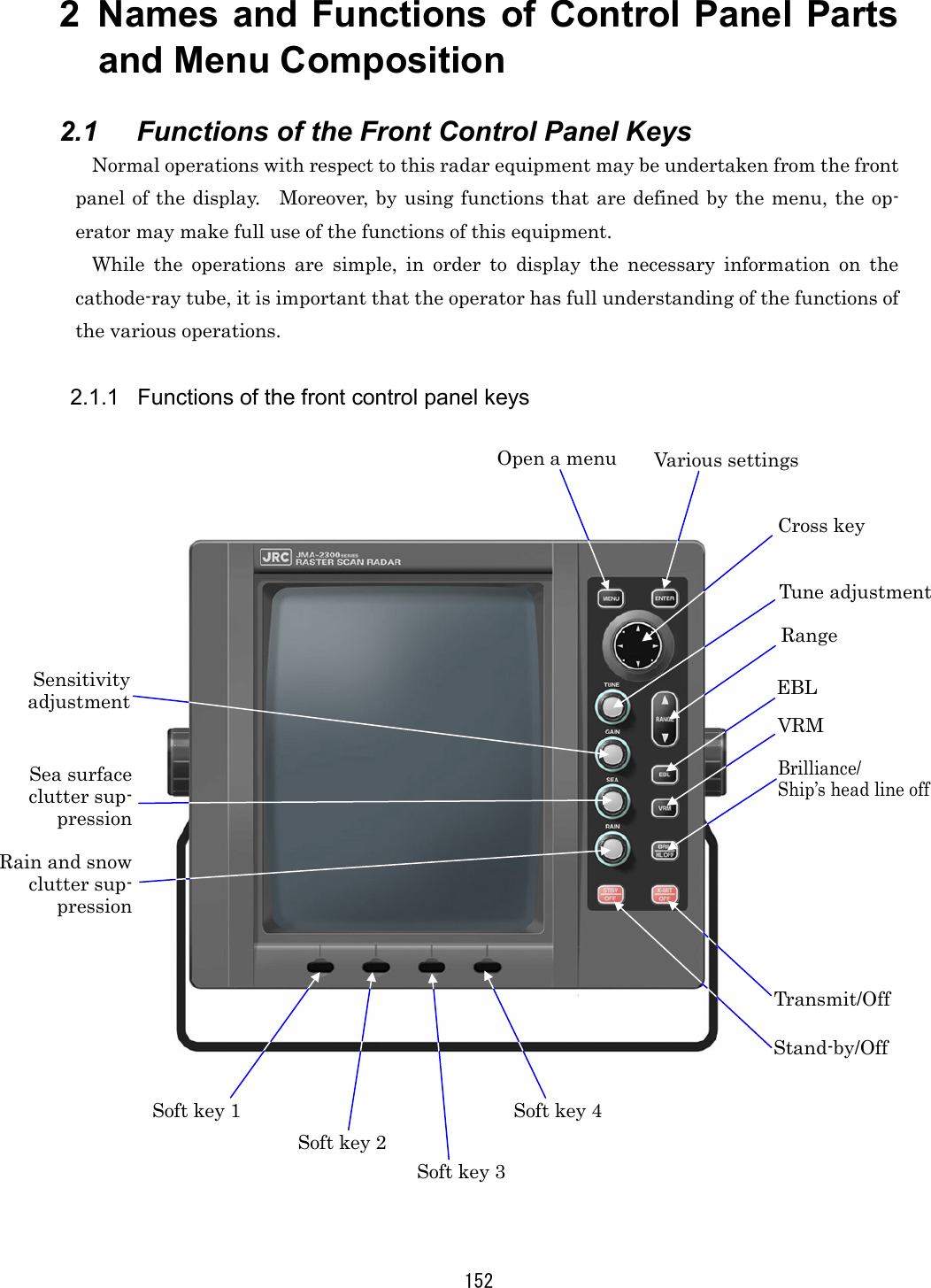
![166 3.1.1 Turning the power ON and starting the system 1111. Turning the power ON. Turning the power ON. Turning the power ON. Turning the power ON In order to turn the power on, push the STBY/OFFSTBY/OFFSTBY/OFFSTBY/OFF key. When the power is turned on, a count down timer is displayed on the screen and the system enters the standby state after 1 minute and 30 seconds. Moreover, cumulative energized time and cumulative transmission time are also dis-played. This is used as an indicator for when maintenance is required. Time displays may incorporate some small errors. 2. Undertake transmission2. Undertake transmission2. Undertake transmission2. Undertake transmission In order to transmit from the standby mode, push the X-MIT/OFFX-MIT/OFFX-MIT/OFFX-MIT/OFF key. When returning from the transmission mode to the standby mode, push the STBY/OFFSTBY/OFFSTBY/OFFSTBY/OFF key. 3.1.2 Tuning operation The tuning operation of this radar equipment may be undertaken manually or automatically. Switching between manual operation and automatic operation is undertaken using the soft key. In the case of automatic tuning, the letter "A" will be displayed at the right of the lower left hand tune level indicator. (a) Switching tuning modes Push the soft key PROCESSPROCESSPROCESSPROCESS . Each time key 3 is pushed, the mode sequentially changes between AAAA----TUNETUNETUNETUNE and MMMM----TUNETUNETUNETUNE and if the manual mode is preferred, key 3 should be pushed so that MMMM----TUNETUNETUNETUNE is selected. (b) Turn the [TUNE] control In the case of manual tuning, rotate the [TUNE] control on the operation panel to maximize the size of the image. The tune level indicator acts as an indicator when undertaking manual tuning and should be adjusted so that the indicator is at the maximum position. In the case of automatic tuning, there is no need to turn the [TUNE] control. In the event no image appears, turn the [GAIN] control on the control panel all the way to the right and set [SEA] control and the [RAIN] control furthermost to the left.](https://usermanual.wiki/Japan-Radio/NKE249.JMA2343-and-JMA2344-Manual-1-of-4/User-Guide-288864-Page-47.png)
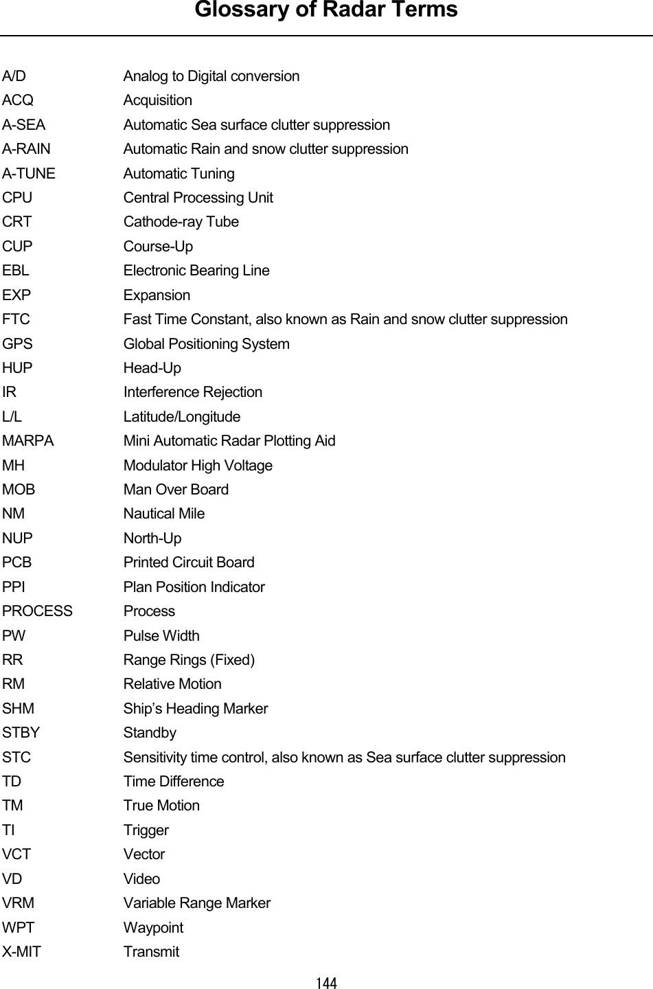
![167 3.1.3 Adjusting monitoring and image Display the optimal image by adjusting the [TUNE] control (in the case of manual tuning), [GAIN] control, [SEA] control and [RAIN] control on the control panel. The range of monitoring distance may be switched by pushing the "▲ (up)" or "▼ (down)" of on RANGERANGERANGERANGE key. The distance range currently selected will be displayed at the lower left hand corner of the display (please refer to "2.2 Explanation of Screen Readout"). 3.1.4 Data acquisition and monitoring Please refer to "3.3 Basic Operations" and "4 How to Interpret the PPI Screen" for the various operations. 3.1.5 Ending the operation and shutting down the system 1. Interrupting the transmission1. Interrupting the transmission1. Interrupting the transmission1. Interrupting the transmission (a) Push the STBY/OFFSTBY/OFFSTBY/OFFSTBY/OFF key. The transmission will be interrupted and the display will return to the standby mode. 2. Shutting the power off2. Shutting the power off2. Shutting the power off2. Shutting the power off (a) Push the X-MITX-MITX-MITX-MIT key and the STBY/OFFSTBY/OFFSTBY/OFFSTBY/OFF key simultaneously. The radar will stop operation and all functions will shut down. WARNING When performing such work as maintenance, shut the power off and dis-connect the power connector between the rectifier and the display to cease supply of electricity to the system. Even if the power switch is off, electricity may be flowing internally in the various equipments and performing maintenance and repair under such conditions may cause accidents such as severe electric shock or equipment breakdown.](https://usermanual.wiki/Japan-Radio/NKE249.JMA2343-and-JMA2344-Manual-1-of-4/User-Guide-288864-Page-48.png)
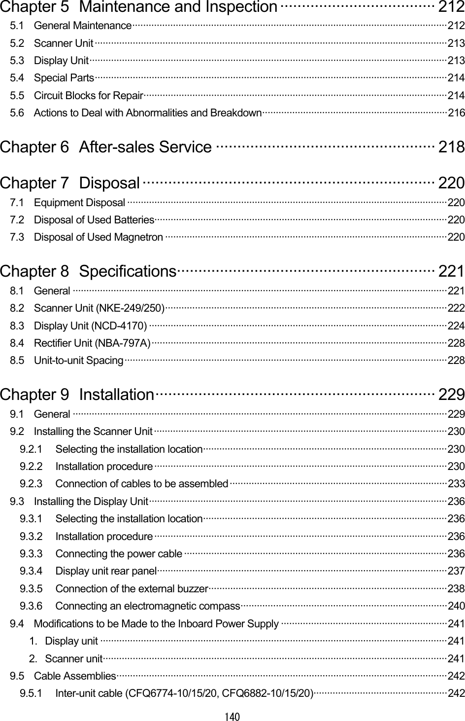
![171 3.3.6 Adjusting the tuning Please refer to "3.1.2 Tuning operation". 3.3.7 Adjusting the sensitivity Please ensure that the sensitivity adjustment is made to an optimal level when undertaking monitoring. If the sensitivity is too low, hazardous objects, ships and other floating objects may not be displayed. If the sensitivity is too high, receiver noise at the PPI screen will increase and this may impair monitoring. (a) Turn the [Gain] control. ・When the control is turned in the counterclockwise direction, the sensitivity de-creases and when the control is turned in the clockwise direction, the sensitivity increases. ・In general, optimal adjustment of sensitivity is as follows. The image size of the echo from the intended target is maximized. It does not come into contact with echoes from other targets. The image of the echo is small as the sensitivity is too low. The sensitivity has been adjusted to an optimal level. Images overlap as the sen-sitivity is too high. Attention](https://usermanual.wiki/Japan-Radio/NKE249.JMA2343-and-JMA2344-Manual-1-of-4/User-Guide-288864-Page-52.png)
![173 3.3.9 In the event of rain or snow CAUTION Refrain from setting the rain and snow clutter suppression function needlessly. Doing so may suppress echoes from targets such as other vessels for hazardous objects in addition to echoes from rain and snow thus impairing detection. When using the rain and snow clutter suppression function, ensure that the suppression setting is always at an optimal level. When rain or snow falls, echo from the rain or snow (rain clutter) appears on the PPI screen making it difficult to see images of echoes from vessels or other objects. By using the [RAIN] control function or the "automatic rain and snow" function, rain clutter may be suppressed facilitating monitoring of the target. When the "automatic rain and snow" function is operating, it is not possible to use the [RAIN] control function. Manual rain and snow clutter suppressionManual rain and snow clutter suppressionManual rain and snow clutter suppressionManual rain and snow clutter suppression (a) Turn the [RAIN] control. As the control is turned to in the clockwise direction, the rain and snow clutter suppression function becomes stronger. Automatic rain and snow clutter suppressiAutomatic rain and snow clutter suppressiAutomatic rain and snow clutter suppressiAutomatic rain and snow clutter suppressionononon (a) Push the soft key PROCESSPROCESSPROCESSPROCESS . (b) Push the soft key 1 and select A-RAINA-RAINA-RAINA-RAIN . Rain and snow clutter suppression is enabled depending on the condition of the image. (c) Push the MENUMENUMENUMENU key. The soft key menu will return to the initial function display. Rain clutter has been suppressed (the image of the echo from the target is also suppressed). Rain clutter is being shown as an image](https://usermanual.wiki/Japan-Radio/NKE249.JMA2343-and-JMA2344-Manual-1-of-4/User-Guide-288864-Page-54.png)