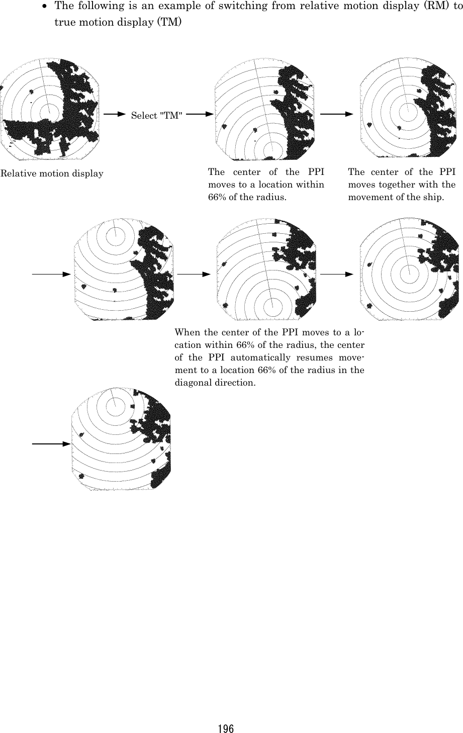
Japan Radio NKE249 Marine Radar User Manual JMA2343 and JMA2344 Manual 2 of 4
Japan Radio Co Ltd. Marine Radar JMA2343 and JMA2344 Manual 2 of 4
Contents
- 1. JMA2343 and JMA2344 Manual 1 of 4
- 2. JMA2343 and JMA2344 Manual 2 of 4
- 3. JMA2343 and JMA2344 Manual 3 of 4
- 4. JMA2343 and JMA2344 Manual 4 of 4
JMA2343 and JMA2344 Manual 2 of 4
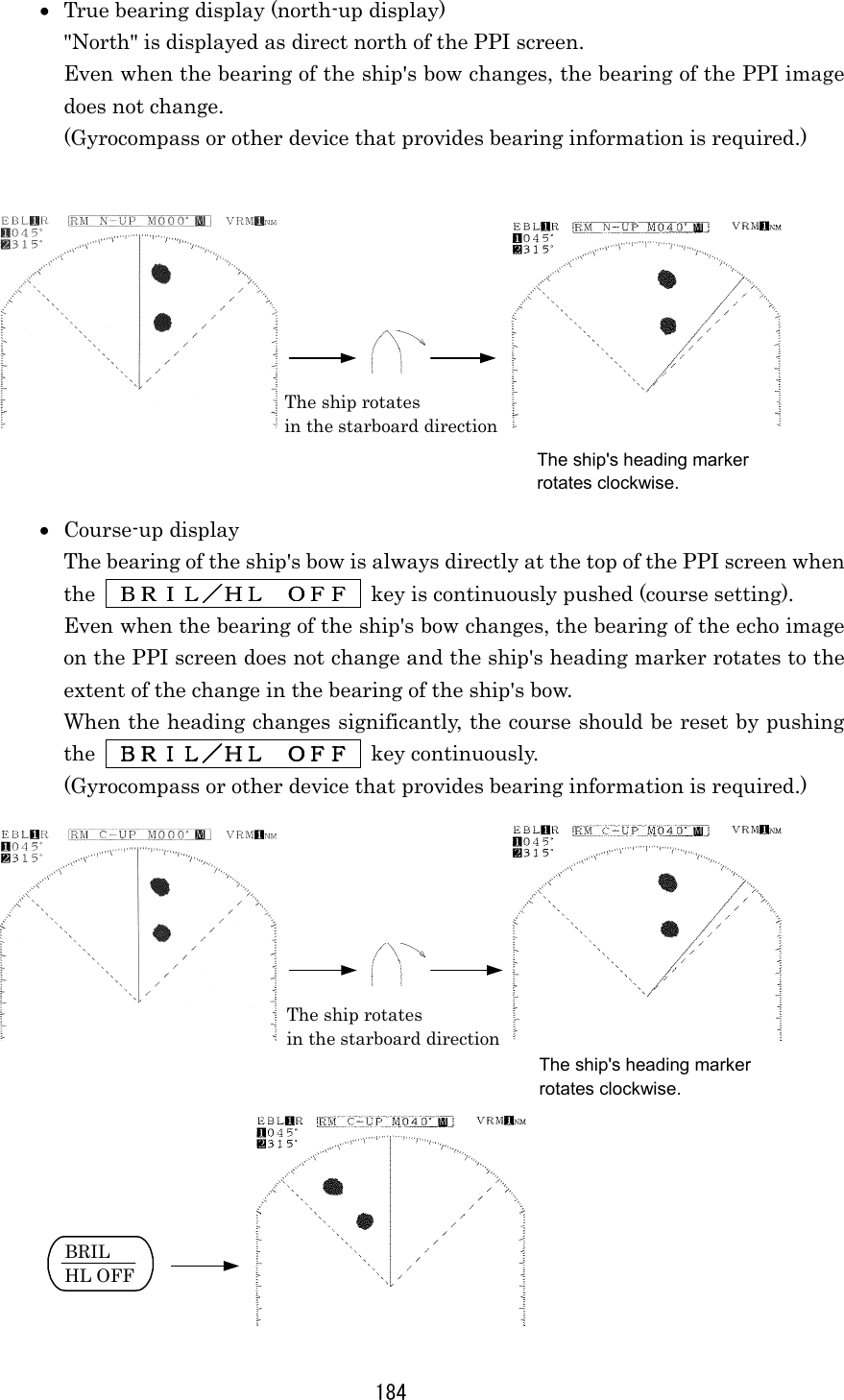
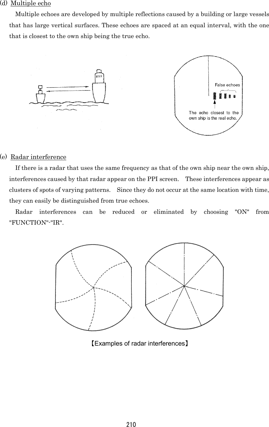
![174 3.3.10 In case of high waves CAUTION On short range scales, the setting of the sea surface clutter suppression should not be advanced to an extent that results in complete suppression of all clutter. Such a setting may suppress echoes from targets such as vessels or hazardous objects in addition to echoes from the waves and thus impair detection. When using the sea surface clutter suppression function, be sure that the sup-pression level is set at the optimum. When sea waves become high, echoes from the high waves (sea clutter) appear on the PPI screen making it difficult to see image of echoes from vessels or other objects. Sea clutter is increasingly prominent to the extent that its source is close to the ship. By using the [SEA] control function or the "automatic sea surface" function, sea surface clutter may be suppressed facilitating monitoring of the targets. Manual sea surface clutter suppressionManual sea surface clutter suppressionManual sea surface clutter suppressionManual sea surface clutter suppression (a) Turn the [SEA] control in the clockwise direction. As the control is turned in the clockwise direction, suppression of sea surface clutter increases. Automatic sea surface clutter suppressionAutomatic sea surface clutter suppressionAutomatic sea surface clutter suppressionAutomatic sea surface clutter suppression (a) Push the soft key PROCESSPROCESSPROCESSPROCESS . (b) Push the soft key 1 to select A-SEAA-SEAA-SEAA-SEA . Sea surface clutter suppression is enabled depend on the condition of the image. (c) Push the MENUMENUMENUMENU key. The soft key will return to the initial function display. Sea clutter being displayed asimage due to high waves. Sea clutter has been suppressed (the image of the echo from the target has also been suppressed).](https://usermanual.wiki/Japan-Radio/NKE249.JMA2343-and-JMA2344-Manual-2-of-4/User-Guide-288865-Page-1.png)
![203 3.5 Miscellaneous Considerations 3.5.1 Replacing the battery (BT1) In order to maintain the information that has been set, the battery (BT1) needs to be replaced at regular intervals. (a) Replacing the battery (BT1) [Type: CR2032-FT6-1, SANYO Electric Co, Ltd.] • Please call the dealer servicing your locality for a replacement battery. (b) Reinitializing • The lithium battery maintains the content of the setting of the menu and soft key even when the power is shut off allowing use under the conditions of the last use. • If this battery runs down, all conditions including the menu will automatically be reset. For this reason, initializing is required after replacement of the battery. When the battery wears down, distance and bearing may become inaccurate. In such cases, the battery should immediately be replaced and initialization un-dertaken. • In the event immediate replacement of the battery is not feasible, initializa-tion should be undertaken each time the power is turned on as an emergency measure. However, each time the power is shut off, the content that has been set is reset. Please refer to "9.8 Initial Setting" with respect to details on initialization. Attention](https://usermanual.wiki/Japan-Radio/NKE249.JMA2343-and-JMA2344-Manual-2-of-4/User-Guide-288865-Page-30.png)
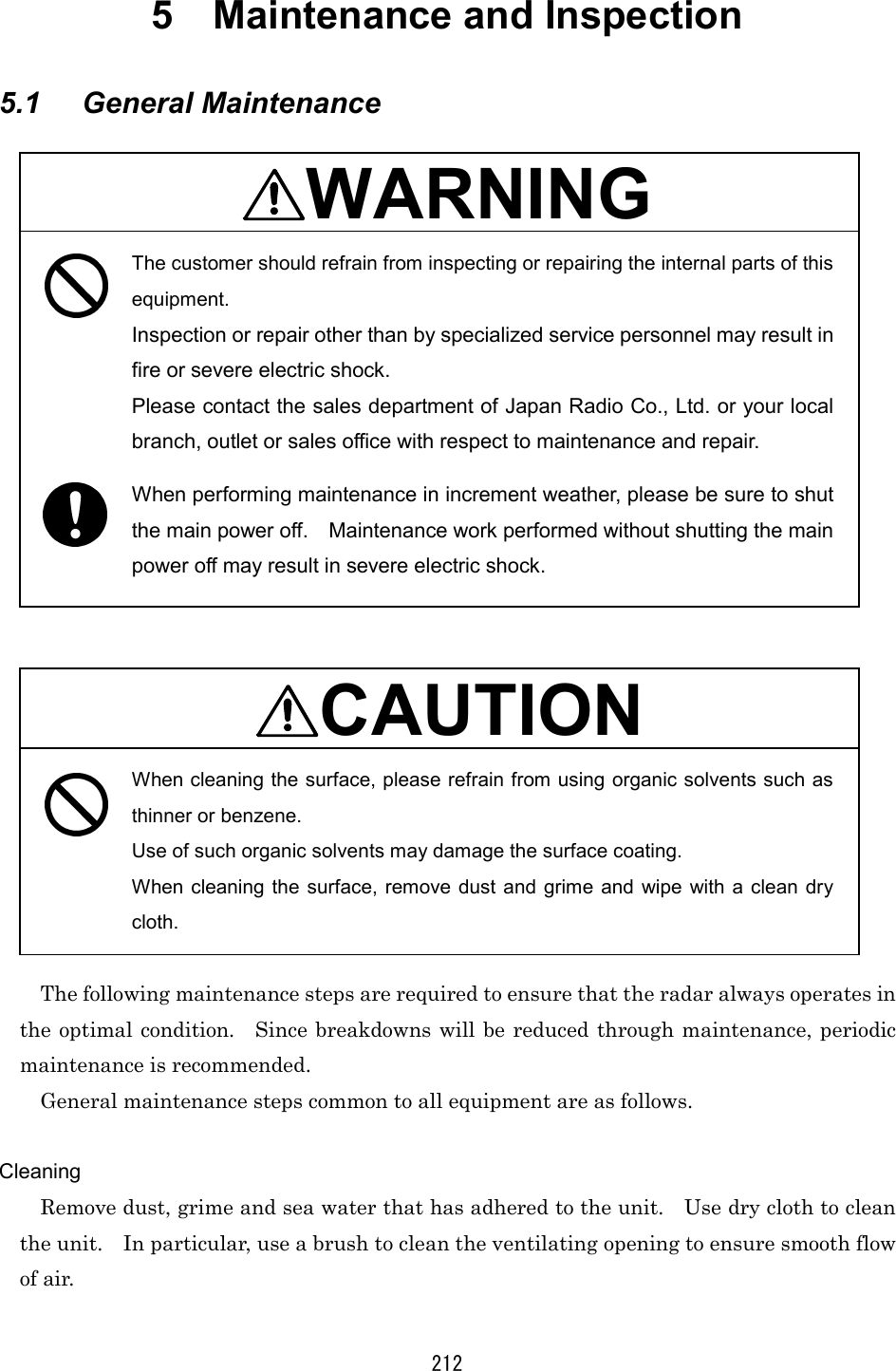
![207 4 How to Interpret the PPI Screen 4.1 Height of and the Distance to the Target The maximum distance to a target that can be observed with a radar depends not only on the power of the radar's transmitter, beam width of the scanner unit, and the receiver's sensitivity but also on height of a target, distance to a target and height of scanner unit line etc. This is because the radio wave emitted by a radar runs straight, undergoing no influence by the curvature of the earth surface. [Distance and Target] For example, when the scanner unit lies 3 meters above the sea level, the radar can detect and display an island with a height of 10 meters at a distance 10 NM away from the scanner unit position but cannot detect and display an island with a height of 5 meters at the same distance. This is theoretically true but does not always hold, depending on weather conditions. For a target located 10 NM away to be displayed on a radar, it theoretically needs to be 7.6 meters or higher. Any targets lower than 7.6 meters cannot be displayed on a radar. The target may be unable to be observed when the height of a scanner unit or an target is low. a1=2.23√h1 a2=2.23√h2 a1 + a2=2.23 (√h1 + √h2 ) a1, a2:Unit [Nautical miles] h1, h2:Unit [Meters] Island not displayed on the screen 10 NM a1+a2(NM) Distance h2(meters) Target height h1(meters) Scanner unit height 10 NM](https://usermanual.wiki/Japan-Radio/NKE249.JMA2343-and-JMA2344-Manual-2-of-4/User-Guide-288865-Page-34.png)
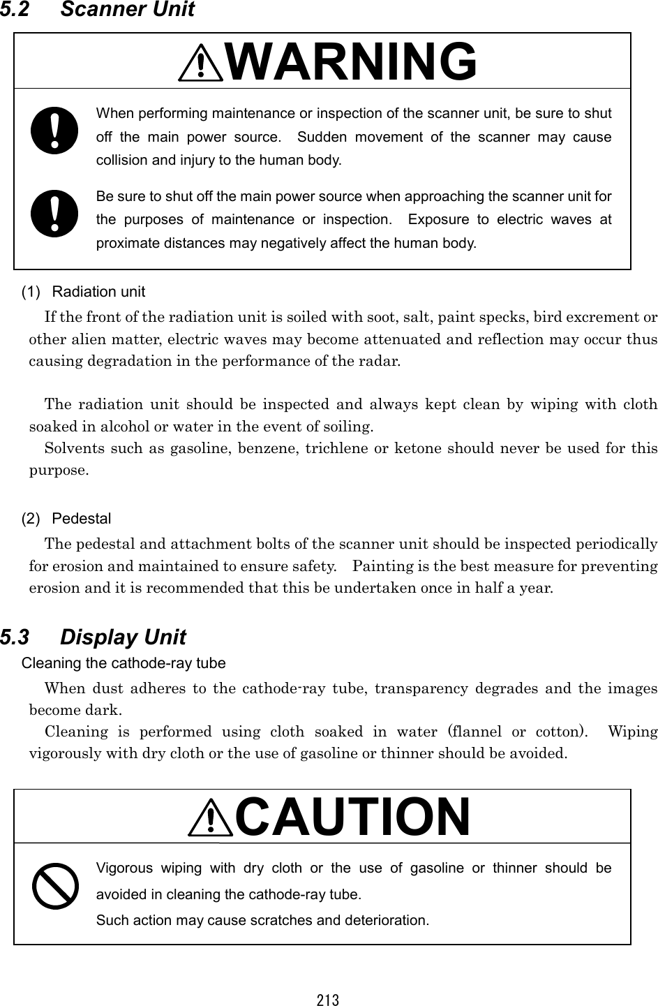
![225 (16) Keys/Controls ・Main panel STBY/OFF key X-MIT/OFF key [TUNE] control [GAIN] control [SEA] control [RAIN] control RANGE key VRM key EBL key BRIL/HL OFF key MENU key ENTER key Cross key ・Software key panel Software key : 4 (17) Software key function ・DISPLAY Screen expansion [EXP] Center move [CENTER] Fixed range rings [RR] Cursor [CUR] ・PROCESS Clutter suppression [AUTOOFF/A-SEA/A-RAIN] Interference rejection [IR] Tune mode [TUNE] Radar wakes [WKS] ・GUARD Zone make [MAKE] Alarm setting [ALM] Sensitivity [SENS] Alarm mode [ALM] OFFOFFOFFOFF STBYSTBYSTBYSTBY OFFOFFOFFOFF XXXX----MITMITMITMIT ▲▲▲▲ RANGE RANGE RANGE RANGE ▼▼▼▼VRMVRMVRMVRM EBLEBLEBLEBL MENUMENUMENUMENU ENTERENTERENTERENTER HL OFFHL OFFHL OFFHL OFF BRILBRILBRILBRIL](https://usermanual.wiki/Japan-Radio/NKE249.JMA2343-and-JMA2344-Manual-2-of-4/User-Guide-288865-Page-52.png)
![226 (18) Menu ・FUNCTION EBL1/VRM1 mode setting [EBL1/VRM1] (Fix [FIX]/Float [FLOAT]/Parallel line [PLINE]) EBL2 setting [EBL2] VRM2 setting [VRM2] EBL read out [EBL READOUT] Zooming of echo image on PPI [ZOOM] True motion/Relative motion [TM*/RM] Heading mode [HDG MODE] (Head-up [H-UP]/North-up [N-UP]*/ Course-up [C-UP]*) Image process [PROCESS] ・DISPLAY Position display [POSITION] (Own ship [L/L or TD]/Cursor [CUR L/L]/ Waypoint [WPT L/L])* Waypoint display [WAYPOINT] Range unit [RANGE] (NM/KY/KM) Timed transmission [TIMED TX] (Transmission period [TX PERIOD]/ Stand-by period [STBY PERIOD]) ・RADAR SET-UP 1 Buzzer volume [BUZZER] Panel dimness [DIMMER] Transmitter pulse width [TX PLSE] (1.5NM/3NM/6NM) Bearing reference [BEARING] (Magnetic bearing [MAG]/True bearing [TRUE])* Multi display unit setting [MULTI DISPLAY] ・RADAR SET-UP 2 Language (English/Japanese/Chinese/Francais/ Espanol/ Italiano/Norsk/Deutsch/Korea)](https://usermanual.wiki/Japan-Radio/NKE249.JMA2343-and-JMA2344-Manual-2-of-4/User-Guide-288865-Page-53.png)
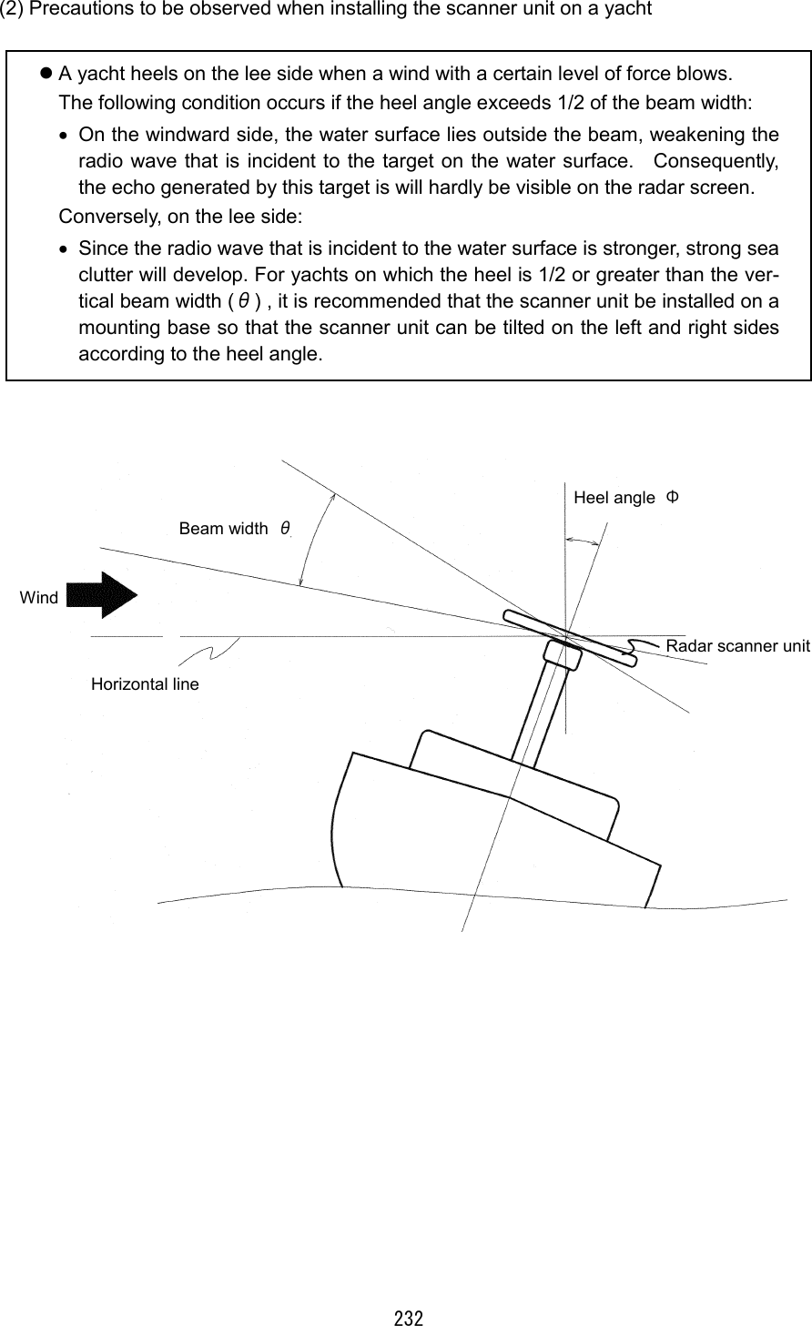
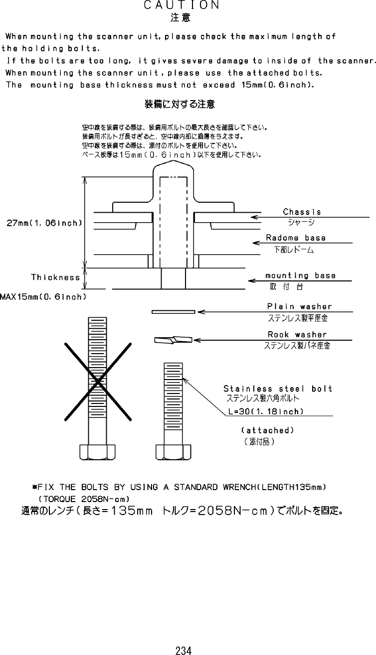
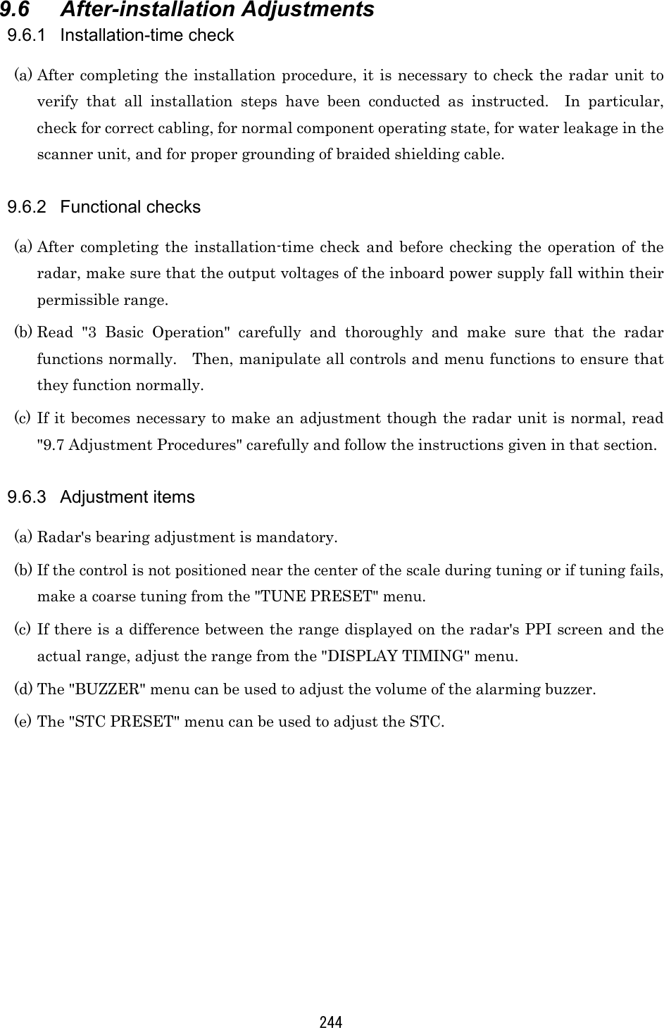
![231 (1) Precautions to be observed when installing the scanner unit on a power boat The bow of a power boat is kept in a raised position when it is running at a high speed. Consequently, if the radar's scanner unit is installed horizontally when the boat is stopped, the following conditions will occur if the trim (elevation angle of the ship's bow at run time) exceeds 1/2 of the vertical beam width (θ): • On the front side, the water surface lies outside the beam, weakening the radio wave that is incident to the target on the water surface. Consequently, the echo generated by this target is will hardly be visible on the radar screen. Conversely, on the rear side: • Since the radio wave that is incident to the water surface is stronger, strong sea clutter will develop. For vessels on which the trim is 1/2 or greater than the ver-tical beam width (θ), it is recommended that the scanner unit be installed in such an orientation that it is tilted forwards. [When the ship is stopped or running at a slow speed] [High speed run: the lower part of the beam is almost horizontal.] Beam width θ Radar scanner unit Horizontal line Beam width θ Radar scanner unit Horizontal line](https://usermanual.wiki/Japan-Radio/NKE249.JMA2343-and-JMA2344-Manual-2-of-4/User-Guide-288865-Page-58.png)
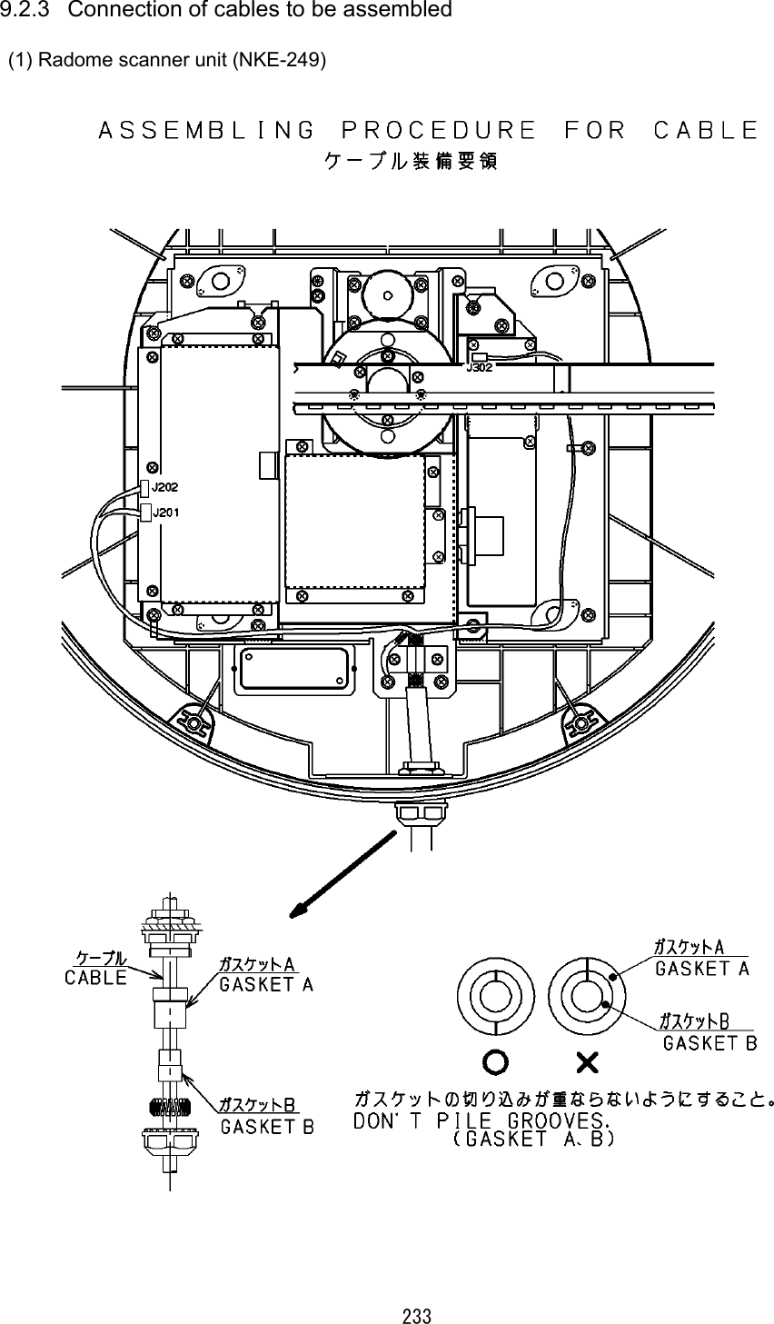
![242 9.5 Cable Assemblies 9.5.1 Inter-unit cable (CFQ6774-10/15/20, CFQ6882-10/15/20) (a) This cable is used to connect the display unit to the scanner unit. (b) Use the following cables with connectors for this radar equipment. Cable length JRC Code for JMA-2343 JRC Code for JMA-2344 Remarks 15m 10m 20m CFQ6774-15 CFQ6774-10 CFQ6774-20 CFQ6882-15 CFQ6774-10 CFQ6882-20 Standard Option Option Color Number of Conduc-tors/Diameter (mm) Signal Name Shielded wire (conductor) : Black 7/0.20 TI Shielded wire (shield) TIE Co-axial cable (conductor) 7/0.20 VD Co-axial cable (shield) VDE Red (Thick) 50/0.18 1A Yellow (Thick) 50/0.18 1A Blue (Thick) 50/0.18 2A Purple (Thick) 50/0.18 2A Green (Thick) 50/0.18 1A Pink (Thick) 50/0.18 1A Gray (Thick) 50/0.18 2A Brown (Thick) 50/0.18 2A Orange (Middle thick) 34/0.18 BP Green 7/0.20 BZ Yellow 7/0.20 COM+ White Twisted pair 7/0.20 COM- ※The outside diameter size of the cable :11.5±0.5 [mm] Only JMA-2344](https://usermanual.wiki/Japan-Radio/NKE249.JMA2343-and-JMA2344-Manual-2-of-4/User-Guide-288865-Page-69.png)
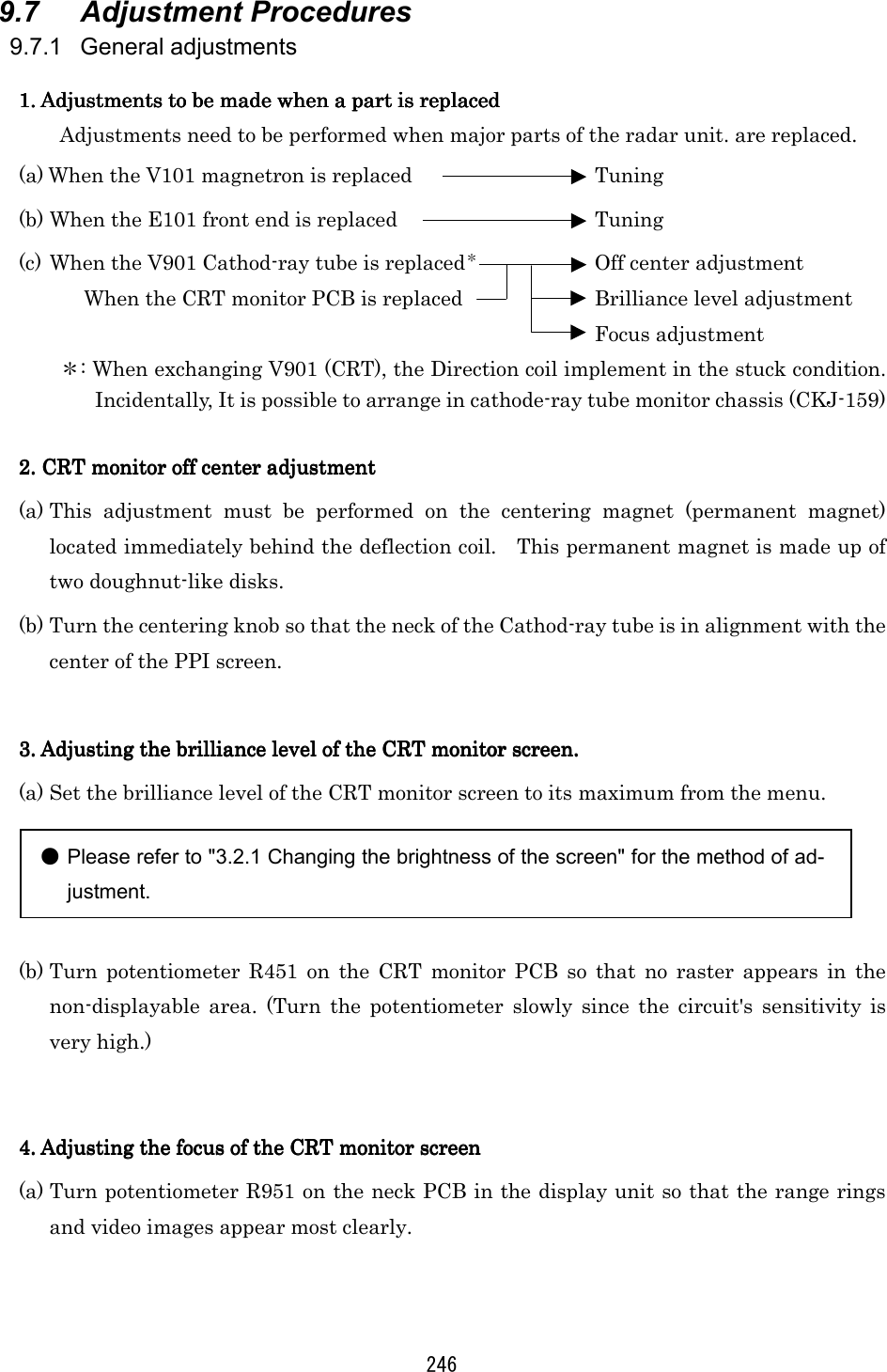
![245 9.6.4 Rectifier unit ● The rectifier unit can run on inboard voltages of 100/110/115 VAC and 200/220/230 VAC provided that connections at the input terminals on the NBA-797A T701 are changed. The figures below show how to change the connections at the input ter-minals. 100/110/115 VAC 200/220/230 VAC [Reconnecting the NBA-797A input terminals] Reconnect according to the input voltage. 115V 110V 100V This terminal must not be reconnected. Reconnect according to the input voltage. 230V 220V 200V This terminal must not be reconnected.](https://usermanual.wiki/Japan-Radio/NKE249.JMA2343-and-JMA2344-Manual-2-of-4/User-Guide-288865-Page-72.png)
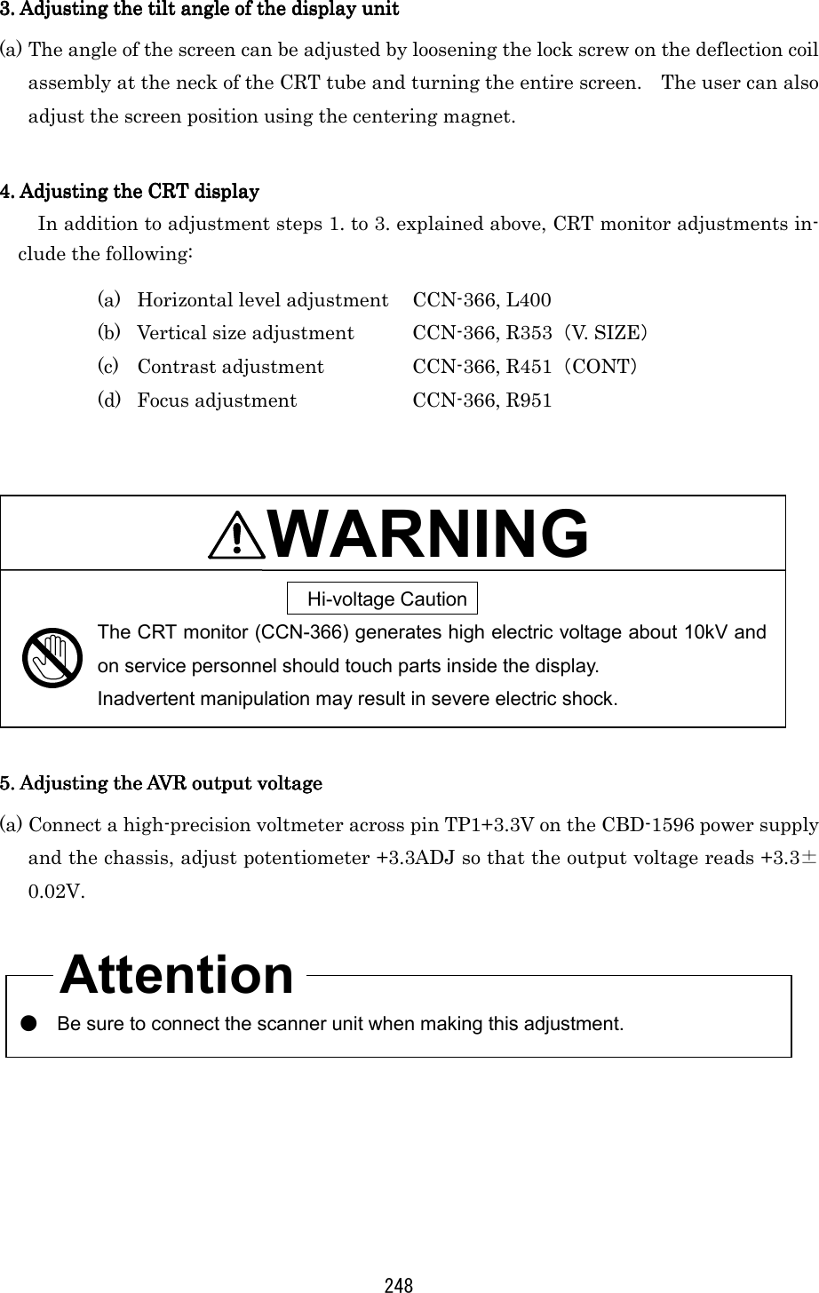
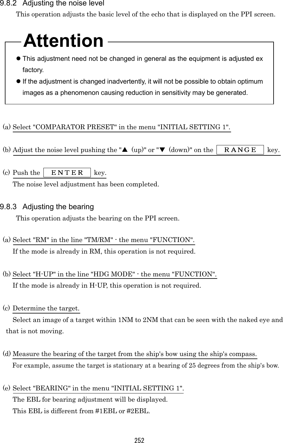
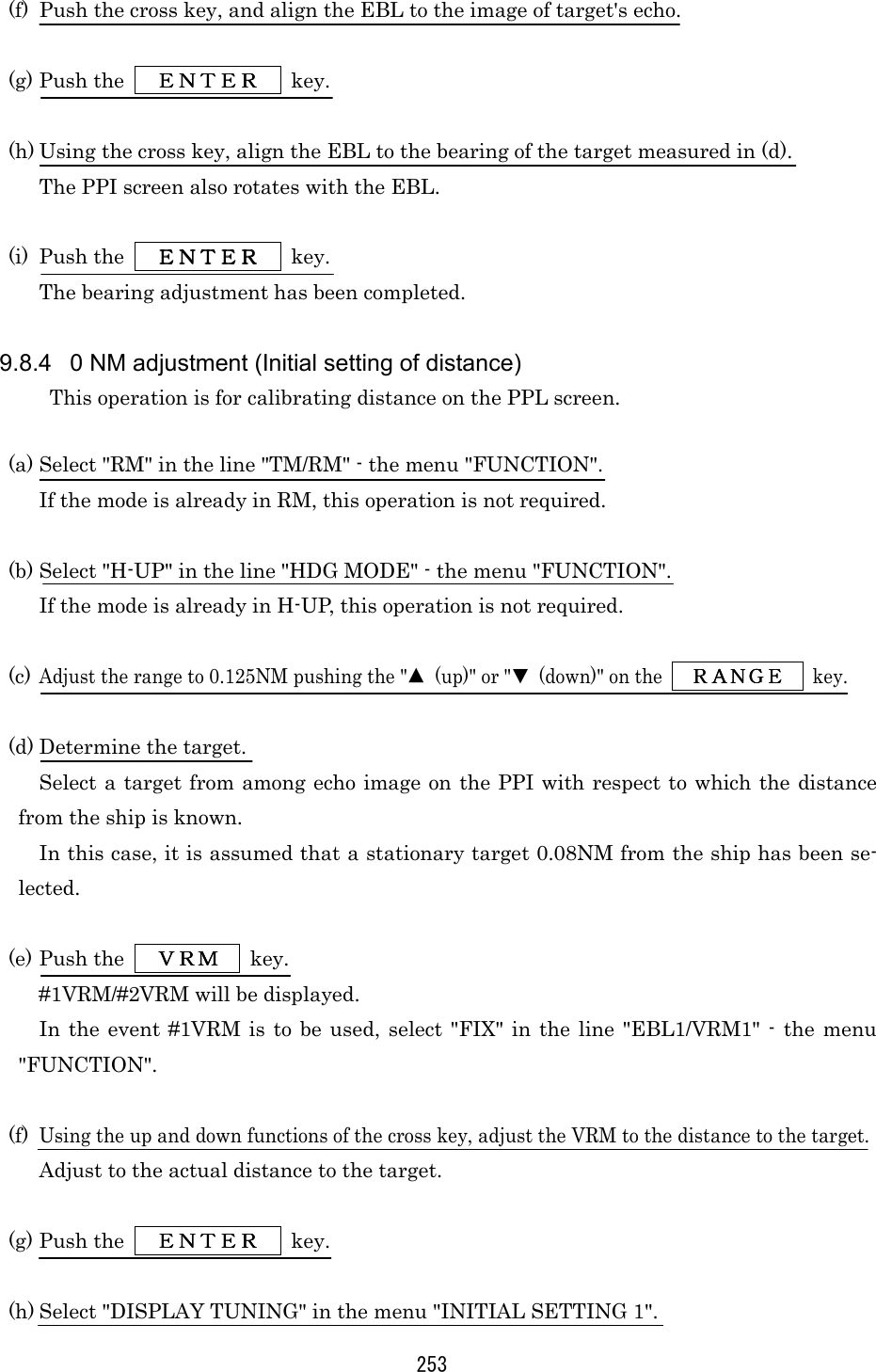
![247 9.7.2 Adjusting the scanner unit The scanner unit has several locations that need adjustment. They are factory set and normally need not be adjusted by the user. If it is necessary to make functional checks during inspection or repair, make the adjustments that are explained below. WARNING Hi-voltage Caution High-tension voltages of 4,000 volts or higher are present at the modulator units (CME-307 or CME-308). The modulator unit must be accessed only by qualified service engineers. Inadvertent manipulation may result in severe electric shock. 1. Adjusting the AVR output voltage from the modulator1. Adjusting the AVR output voltage from the modulator1. Adjusting the AVR output voltage from the modulator1. Adjusting the AVR output voltage from the modulator (a) Place the radar unit into the transmission state (the range scale set to 12NM), connect a VOM across J203-14PIN on the CME-307 or CME-308 and the GND terminal, and adjust RV2 so that the output voltage reads +8 volts. 2. Adjusting the tuning indicator level of the receiver2. Adjusting the tuning indicator level of the receiver2. Adjusting the tuning indicator level of the receiver2. Adjusting the tuning indicator level of the receiver (a) If the tuning mode is set to "AUTO", reset it to "MANUAL". (b) Tune the receiver with the range scale set to 12 NM. 9.7.3 Adjusting the display unit The display unit has several locations that need adjustment. They are factory set and normally need not be adjusted by the user. If it is necessary to make functional checks during inspection or repair, make the adjustments that are explained below. 1. Adjusti1. Adjusti1. Adjusti1. Adjusting the brilliance levelng the brilliance levelng the brilliance levelng the brilliance level (a) Set the brilliance level of the screen to its maximum from the [BRIL] key. (b) Turn potentiometer R451 on the CRT monitor PCB so that no raster appears in the non-displayable area. (Turn the potentiometer slowly since the circuit's sensitivity is very high.) 2. Adjusting the focus of the CRT monitor screen2. Adjusting the focus of the CRT monitor screen2. Adjusting the focus of the CRT monitor screen2. Adjusting the focus of the CRT monitor screen (a) Turn potentiometer R951 on the neck PCB in the display unit so that the range rings and video images appear most clearly.](https://usermanual.wiki/Japan-Radio/NKE249.JMA2343-and-JMA2344-Manual-2-of-4/User-Guide-288865-Page-74.png)
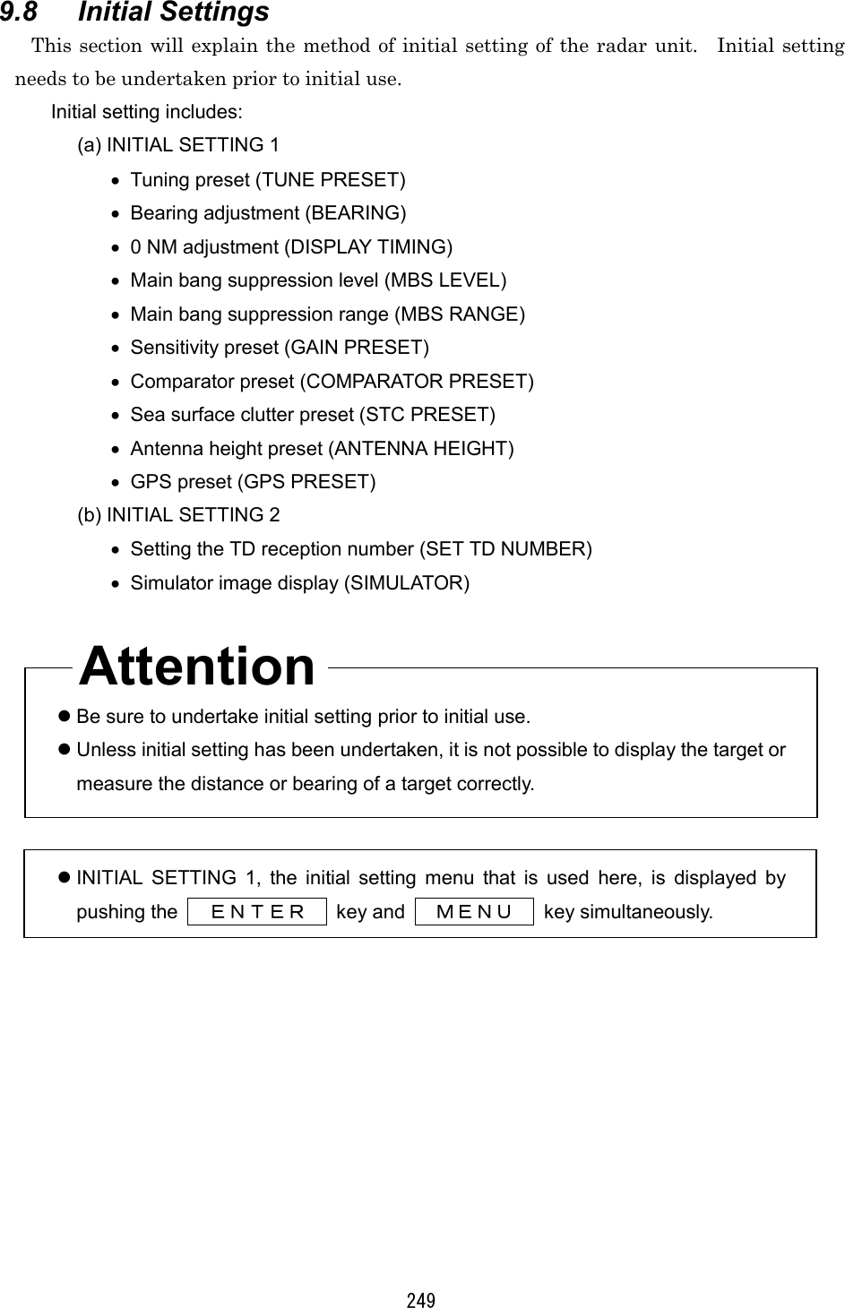
![250 9.8.1 Adjustment of the receiver This adjustment need not be changed in general as the equipment is adjusted ex-factory. If the adjustment is changed inadvertently, it will not be possible to obtain the op-timum tuning even when the TUNE control is operated. 1. Tune preset1. Tune preset1. Tune preset1. Tune preset Here, rough adjustment of the tune will be undertaken. (a) Set the range to 12NM pushing the "▲(up)" or "▼ (down)" on the RANGERANGERANGERANGE key. (b) Push the soft key PROCESSPROCESSPROCESSPROCESS . (c) Push the soft key 3 and select M-TUNEM-TUNEM-TUNEM-TUNE . The method of tuning has been set to "manual". (If the mode is already in manual tuning, this operation is not required.) (d) Push the MENUMENUMENUMENU key and close the soft key menu. (e) Push the X-MIT/OFFX-MIT/OFFX-MIT/OFFX-MIT/OFF switch and wait for 10 minutes or more. Transmission will begin. After about 10 minutes, the transmission frequency will stabilize. (f) Turn the [TUNE] control to the mid position. (g) Select "TUNE PRESET" in the line "RECEIVER ADJUST" - the menu "INITIAL SETTING 1". (h) Pushing the "▲ (up)" or "▼ (down)" on the RANGERANGERANGERANGE key, adjust so that the PPI image becomes the maximum size. (i) Push the ENTERENTERENTERENTER key. The adjustment has been completed.](https://usermanual.wiki/Japan-Radio/NKE249.JMA2343-and-JMA2344-Manual-2-of-4/User-Guide-288865-Page-77.png)
![251 2. Adjusting the central frequency2. Adjusting the central frequency2. Adjusting the central frequency2. Adjusting the central frequency Adjustment is undertaken so that the image is largest when the deflection of the tune level indicator is at the maximum. (a) Undertake operations (a) through (e) of "1.Tune Preset". (b) Adjust the image to the maximum using the [TUNE] control. (c) Select "TUNE FREQUENCY" in the line "RECEIVER ADJUST" - the menu "INITIAL SETTING 1". (d) Adjust to maximize the deflection of the tune level indicator pushing the "▲ (up)" or "▼ (down)" on the RANGERANGERANGERANGE key. (e) Push the ENTERENTERENTERENTER key. The adjustment has been completed. 3. Adjusting the level of the tune level indicator3. Adjusting the level of the tune level indicator3. Adjusting the level of the tune level indicator3. Adjusting the level of the tune level indicator Adjust the scale to correspond to the maximum deflection of the tune level indicator bar. (a) Undertake operations (a) through (e) of "1.Tune Preset". (b) Using the [TUNE] control, adjust to maximize the deflection of the tune level in-dicator. (c) Select "TUNE LEVEL IND" in the line "RECEIVER ADJUST" - the menu "INI-TIAL SETTING 1". (d) Adjust so that the deflection of the tune level indicator is 80% to 90% of the indicator area pushing the "▲ (up)" or "▼ (down)" on the RANGERANGERANGERANGE key. (e) Push the ENTERENTERENTERENTER key. The adjustment has been completed.](https://usermanual.wiki/Japan-Radio/NKE249.JMA2343-and-JMA2344-Manual-2-of-4/User-Guide-288865-Page-78.png)
![255 (b) Select the height of the radar antenna among "UNDER 5m", "5m TO 10m", and "MORE THAN 10m". 9.8.6 Presetting the sensitivity This operation sets the maximum sensitivity when [GAIN] control is turned. This adjustment should not be undertaken without reason. When undertaking this adjustment, also undertake "9.8.2. Adjustment of the Noise Level". (a) Push the soft key DISPLAYDISPLAYDISPLAYDISPLAY . (b) Push the soft key 1 and select EXPEXPEXPEXP OFFOFFOFFOFF . (c) Turn the [RAIN] control to the minimum (turn to maximum counterclockwise). (d) Turn the [SEA] control to the minimum (turn to maximum counterclockwise). (e) Turn the [GAIN] control to the maximum (turn to maximum clockwise). This maximizes the strength of the echo on the PPI screen. (f) Select "GAIN PRESET" in the menu "INITIAL SETTING 1". (g) Adjust the sensitivity level pushing the "▲ (up)" or "▼ (down)" on the RANGERANGERANGERANGE key. (h) Push the ENTERENTERENTERENTER key. The maximum level of gain has been set. 9.8.7 Presetting the sea clutter This operation sets the maximum level of suppression when the [SEA] control is turned. This adjustment should not be undertaken without reason. (a) Set the range to 0.125NM pushing the "▼ (down)" on the RANGERANGERANGERANGE key. (b) Undertake tuning adjustment using the [TUNE] control. (c) Push the soft key DISPLAYDISPLAYDISPLAYDISPLAY .](https://usermanual.wiki/Japan-Radio/NKE249.JMA2343-and-JMA2344-Manual-2-of-4/User-Guide-288865-Page-82.png)
![256 (d) Push the soft key 1 and select EXPEXPEXPEXP OFFOFFOFFOFF . (e) Turn the [GAIN] control to the maximum (turn to maximum clockwise). (f) Turn the [RAIN] control to the minimum (turn to maximum counterclockwise). (g) Turn the [SEA] control to the maximum (turn to maximum clockwise). The strength of the echo on the PPI screen is maximized with sea surface clutter sup-pression maximized. (h) Select "STC PRESET" in the menu "INITIAL SETTING 1". (i) Adjust the level of suppression pushing the "▲ (up)" or "▼ (down)" on the RANGERANGERANGERANGE key. The PPI screen near the center adjusts to the grade projected slightly. (j) Push the ENTERENTERENTERENTER key. Suppression of sea surface clutter has been set at the maximum level. 9.8.8 Suppression of main bang This adjustment is undertaken to suppress main bang that is the reflected signal from three dimensional circuits such as the wave guide that normally appears at the center of the radar display as a circle. Optimum adjustment is achieved when the main bang image remains lightly on the screen. This adjustment should not be undertaken without reason. Erroneous adjust-ment may cause targets that are proximate to be erased from the screen. (a) Set the range to 0.125NM pushing the "▼ (down)" on the the RANGERANGERANGERANGE key. (b) Select "OFF" in the line "PROCESS" - the menu "FUNCTION". (c) Push the soft key DISPLAYDISPLAYDISPLAYDISPLAY . Attention](https://usermanual.wiki/Japan-Radio/NKE249.JMA2343-and-JMA2344-Manual-2-of-4/User-Guide-288865-Page-83.png)
![257 (d) Push the soft key 1 and select EXPEXPEXPEXP OFFOFFOFFOFF . (e) Push the the soft key PROCESSPROCESSPROCESSPROCESS . (f) Push the soft key 1 and select AUTOAUTOAUTOAUTO OFFOFFOFFOFF . (g) Turn the [GAIN] control to the maximum (turn to maximum clockwise). (h) Turn the [SEA] control to the mid position. (i) Turn the [RAIN] control to the minimum (turn to maximum counterclockwise). (j) Select "MBS LEVEL" in the menu "INITIAL SETTING 1". (k) Adjust the suppression level pushing the "▲ (up)" or "▼ (down)" on the RANGERANGERANGERANGE key. (l) Push the ENTERENTERENTERENTER key. The suppression level of the main bang has been determined. (m) Select "MBS RANGE" in the menu "INITIAL SETTING 1". (n) Adjust the suppression range pushing the "▲ (up)" or "▼ (down)" on the RANGERANGERANGERANGE key. (o) Push the ENTERENTERENTERENTER key. Adjustment of the suppression range of the main bang has been completed. 9.8.9 Display of simulator image By activating this function, it is possible to display a demonstration screen on the PPI screen. To make the setting of this function effective, the power must be once switched off. (a) Push the STBY/OFFSTBY/OFFSTBY/OFFSTBY/OFF key. The display will enter the standby mode.](https://usermanual.wiki/Japan-Radio/NKE249.JMA2343-and-JMA2344-Manual-2-of-4/User-Guide-288865-Page-84.png)