Japan Radio NKE3710 MARINE RADAR User Manual
Japan Radio Co Ltd. MARINE RADAR Users Manual
UserManual.wiki
>
Japan Radio
>
NKE3710 User Manual
>
User Manual 3
Contents
1.
User Manual 1
2.
User Manual 2
3.
User Manual 3
User Manual 3
Navigation menu
Upload a User Manual
Namespaces
Wiki Guide
HTML
PDF
Info
Views
User Manual
Discussion / Help
Navigation
![4-2 4.1 Use of Navigation Tools yyyy4 4.1.1 Using Cursor (Cursor) Procedures 1 Move the cursor onto the PPI display by moving the trackball. When the cursor is moved onto the PPI display, the arrow cursor turns into a cross cursor. 4.1.2 Using Range Rings [RR / HL] Procedures 1 Press the [RR / HL] key. The range ring display switches disappear and appear between display and non-display each time the [RR / HL] key is pressed. The range ring interval is shown in the Range Rings display on / off (upper left of the display ② on page 2-16). The range between the target and own ship can be determined by visually measuring the target's position that lies between two range rings. For change of the brilliance of range rings, refer to Section 3.8.5.](https://usermanual.wiki/Japan-Radio/NKE3710.User-Manual-3/User-Guide-2120533-Page-3.png)
![4-4 4.1 Use of Navigation Tools yyyy4 [I] Operating EBL (EBL) To operate EBL Procedures 1 Press the [EBL1] or [EBL2] key. The EBL adjustment (upper right of the display ⑤/⑦ on page 2-19) will be highlighted, and the selected EBL becomes operable. 2 Turn the [EBL] dial. To turn the [EBL] dial to the right, turn the EBL control clockwise, to turn the [EBL] dial to the left, turn the EBL control counterclockwise. Cancellation 1 Press the [EBL1] or [EBL2] key again. The selected EBL display will disappear. [II] Moving the Starting Point of EBL The system provides three types of EBL starting points. Select one of them in accordance with purpose. :The EBL starting point is defined as the own ship's position. C :The EBL starting point is moved and fixed on the radar display. D :The EBL starting point is moved and fixed at the latitude and longitude. (The navigator needs to be connected.) To move the starting point of EBL Procedures 1 Make EBL1 or EBL2 operable. 2 Press the [EBL] dial to set C or D for the EBL1 / EBL2 starting point mode switching (upper right of the display ⑪/⑫ on page 2-19). The selected EBL starting point mode is switched as shown below each time the dial is pressed. ⇒ C ⇒ D ⇒ 3 Put the cursor on the EBL starting point is to be moved, and press the [ENT] key. The selected EBL starting point will be determined.](https://usermanual.wiki/Japan-Radio/NKE3710.User-Manual-3/User-Guide-2120533-Page-5.png)
![4-5 To return the EBL starting point to own ship's position Procedures 1 Make EBL1 or EBL2 operable. 2 Press the [EBL] dial to set for the EBL1 / EBL2 starting point mode switching (upper right of the display ⑪/⑫ on page 2-19). The selected EBL starting point will be set as the own ship's position. [III] Setting EBL Operation Mode To set the numeric value display mode of EBL (EBL Bearing REF) Determine whether to display EBL in true bearing mode or relative bearing mode. Procedures 1 Put the cursor on the EBL1/2 numeric value indication true / relative switching (upper right of the display ⑨/⑩ on page 2-19), and press the [ENT] key. The selected mode is switched as shown below each time the [ENT] key is pressed. T ⇒ R ⇒ T T :EBL bearing is displayed in true bearing mode. R :EBL bearing is displayed in relative bearing mode. To set a mode for fixing EBL display (EBL Bearing Fix) When this function is set to Angle , an EBL is fixed to the preset bearing. For example, if a true bearing of 020° is preset, the EBL is fixed to the true bearing 020° even when the own ship turns. When the function is set to Screen , the EBL is fixed on the radar display. In this case, the EBL is always fixed to the same bearing on the display when the own ship turns. Procedures 1 Press the [RADAR MENU] key twice. 2 Open the EBL/Cursor Setting menu by performing the following menu operation. 5. Sub Menu 9. EBL/Cursor Setting 3 Press [1] or [2] key. To set EBL1, press the [1] key, to set EBL2, press the [2] key Angle :EBL bearing is fixed to the preset value. Screen :EBL bearing is fixed on the radar display. Note: Course data is necessary for turning on this function.](https://usermanual.wiki/Japan-Radio/NKE3710.User-Manual-3/User-Guide-2120533-Page-6.png)
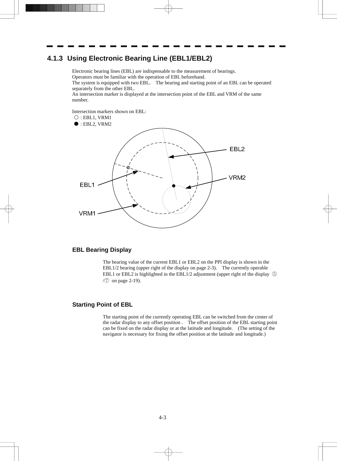
![4-6 4.1 Use of Navigation Tools yyyy4 4.1.4 Using Variable Range Marker (VRM1 / VRM2) Variable range markers (VRM) are indispensable to the measurement of ranges. Operators must be familiar with the operation of VRM beforehand. The system is equipped with two VRM. The VRM can be operated separately from each other. An intersection marker is displayed at the intersection point of the VRM and EBL of the same number. When the starting point of an EBL is offset, the center of the VRM is defined as the offset EBL starting point. Intersection markers shown on VRM: : EBL1, VRM1 : EBL2, VRM2 VRM Operation The range value of the current VRM1 or VRM2 on the PPI display is shown in the VRM1/2 range (upper right of the display on page 2-3). The currently operable VRM1 or VRM2 is highlighted in the VRM1/2 adjustment (upper right of the display ⑥/⑧ on page 2-19). To operate VRM Procedures 1 Press the [VRM1] or [VRM2] key. The VRM adjustment (upper right of the display ⑥/⑧ on page 2-19) will be highlighted, and the selected VRM becomes operable. 2 Turn the [VRM] dial. To turn the [VRM] dial to the right, the VRM control wide, to turn the [VRM] dial to the left, the VRM control narrow. Cancellation 1 Press the [VRM1] or [VRM2] key again. The selected EBL display will disappear.](https://usermanual.wiki/Japan-Radio/NKE3710.User-Manual-3/User-Guide-2120533-Page-7.png)
![4-7 4.1.5 Using Parallel Index Lines (PI Menu) Parallel index lines can be displayed. [I] Operating Parallel Index Lines (PI) Procedures 1 Press the [VRM] dial. Parallel index lines and the PI Menu will appear. To change the bearing of parallel index lines, turn the [EBL] dial, to change the line interval, turn the [VRM] dial. The bearing and interval of parallel index lines are displayed in the PI Menu. 2 Press the [VRM] dial again. The parallel index lines will be fixed. Note: Parallel index lines are operable only while the PI Menu is displayed. When the menu is closed, the parallel index line display remains, but the settings of the bearing and interval cannot be adjusted any more. To adjust the bearing and interval after closing the menu, press the [VRM] dial twice to open the PI Menu. Cancellation 1 Press the [VRM] dial again. The parallel index line display will disappear.](https://usermanual.wiki/Japan-Radio/NKE3710.User-Manual-3/User-Guide-2120533-Page-8.png)
![4-8 4.1 Use of Navigation Tools yyyy4 [II] Operation of Parallel Index Lines Parallel index lines rotate in the same direction as you turn the [EBL] dial. ( ① , ② ) The intervals of parallel index lines narrow when you turn the [VRM] dial counterclockwise ( ③ ), and widen when you turn the [VRM] dial clockwise ( ④ ). HLEBL1 EBL2 VRM1 VRM2 When the [VRM] dial is pressed, the PI Menu closes and the parallel index lines are fixed. During the operation of parallel index lines, pressing the [EBL1] or [EBL2] key disables operation for rotation directions. Pressing the [VRM1] or [VRM2] key disables operation for parallel index line intervals.](https://usermanual.wiki/Japan-Radio/NKE3710.User-Manual-3/User-Guide-2120533-Page-9.png)
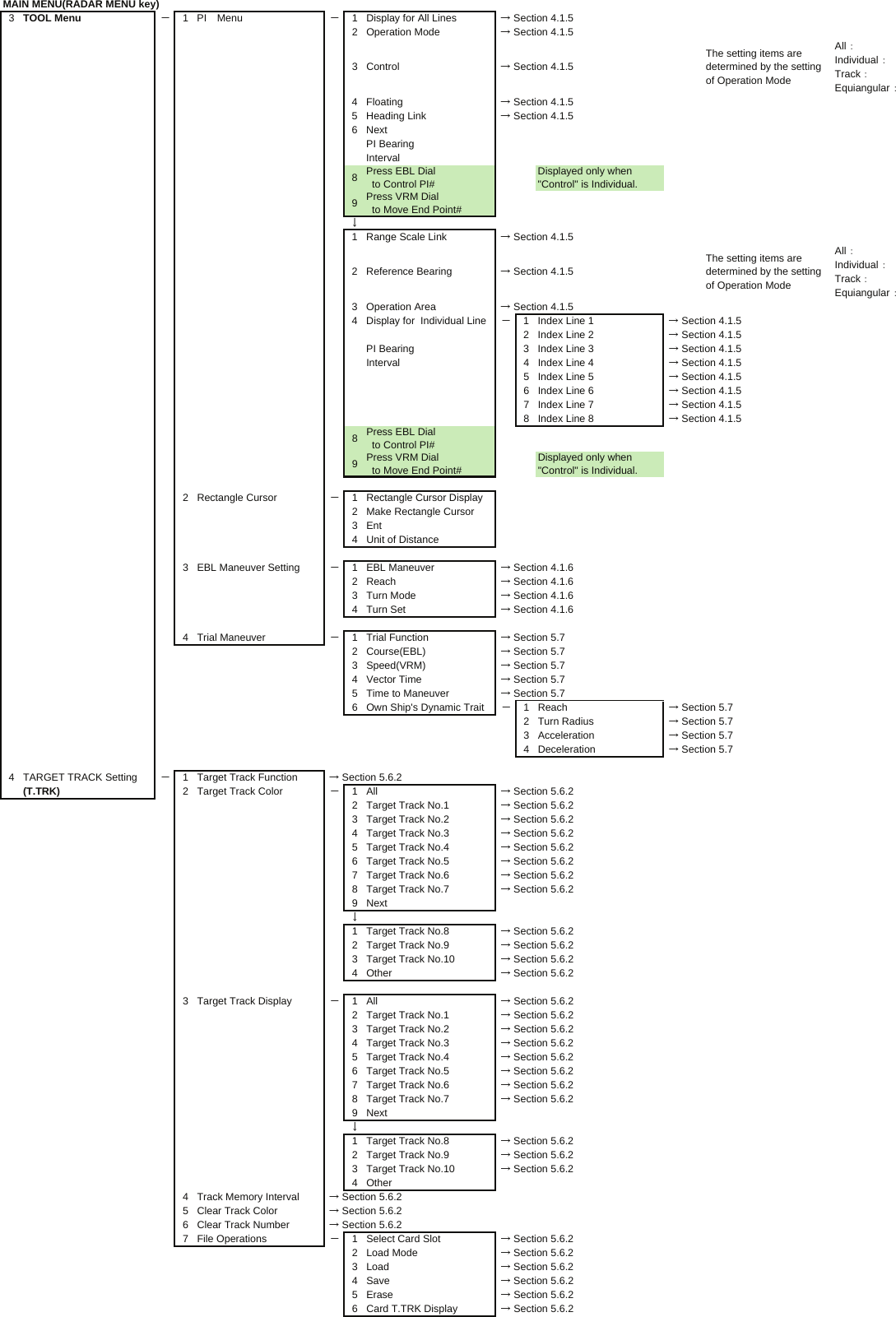
![4-9 [III] Settings in PI Menu The operation of parallel index lines can be set in the PI Menu. Procedures 1 Open the PI Menu by performing the following menu operation. Tool 1. PI Menu [1] Display for All Lines Sets the parallel index line display to on or off. On :Parallel index lines are displayed. Off :Parallel index lines are not displayed. [2] Operation Mode Sets an operation mode for parallel index lines. All :All the parallel lines are operated at the same time. Individual :The bearing of each line is operated individually. Track :Equally spaced lateral lines are displayed on both sides. Equiangular :Two lines intersecting at the center of a circle are displayed. All IndividualTrack EquiangularPIPI PIPI](https://usermanual.wiki/Japan-Radio/NKE3710.User-Manual-3/User-Guide-2120533-Page-10.png)
![4-10 4.1 Use of Navigation Tools yyyy4 Operation if Individual is selected A line perpendicular to the own ship and the intersection marker "----○" are displayed on an operable line. Turning the [EBL] dial changes the direction. Pressing the [VRM] dial changes the range, end point 1, or end point 2 to be operated. An operable point is displayed with " " and can be operated by turning the [VRM] dial. If Sequential is selected for [3] Control, the parallel index lines of the next number can be displayed by pressing the [EBL] dial. To close the menu, press [0] key. Operation if Equiangular is selected Select a group of lines to be operated according to the setting of [3] Control. Pressing the [EBL] dial switches between the direction change mode and elevation-angle change mode. Turning the [EBL] dial changes the direction or elevation angle. [3] Control Determines whether to operate all the lines at the same time. The setting items are determined by the setting of [2] Operation Mode. If All is selected The setting cannot be changed. All : All the lines are operated at the same time. If Individual is selected Determine whether to set consecutive lines or individual lines. Sequential : Lines are operated sequentially. Index Line1 to Line8 : A specified line is operated. If Track or Equiangular is selected Select a group of lines to be operated. Group1 to Group4 : A specified group is operated. [4] Floating Moves the center point of parallel index lines. Off : The starting point of parallel index lines is defined as the own ship's position. Screen Fix : The center of parallel index lines is moved and fixed on the radar display. L/L Fix : The center of parallel index lines is moved and fixed at the latitude and :longitude. (The navigator needs to be connected.) [5] Heading Link Determines whether to operate parallel index lines following the heading bearing. On : Parallel index lines are operated following the heading bearing. Off : Parallel index lines are not operated following the heading bearing.](https://usermanual.wiki/Japan-Radio/NKE3710.User-Manual-3/User-Guide-2120533-Page-11.png)
![4-11 [6] Next Moves to the next page. [1] Range Scale Link Determines the operation of parallel index line intervals when the range is changed. On : The intervals are fixed with the actual range (nm). The appearance of parallel index line intervals changes when the range is changed. Off : The intervals are fixed with the display range. The parallel index line intervals (nm) change when the range is changed. [2] Reference Bearing Sets a reference bearing for the numeric data display of parallel index lines. The setting items are determined by the setting of [2] Operation Mode. If All is selected True : Displayed with true bearing (with North as reference). HL : Displayed with the heading line as reference. If Individual is selected True : Displayed with true bearing (with North as reference). HL : Displayed with the heading line as reference. Index Line1 to Line8 : Displayed with a specified line as reference. If Track is selected True : Displayed with true bearing (with North as reference). HL : Displayed with the heading line as reference. Index Line1 to Line8 : Displayed with a specified line as reference. Line1 , Line3 , Line5 , and Line7 correspond to Group1 , Group2 , Group3 , and Group4 , respectively. If Equiangular is selected The setting cannot be changed. [3] Operation Area If All is selected for [2] Operation Mode, this function sets an area for displaying parallel index lines. One Side : Parallel index lines are displayed only on one side. Both Sides : Parallel index lines are displayed on both sides.](https://usermanual.wiki/Japan-Radio/NKE3710.User-Manual-3/User-Guide-2120533-Page-12.png)
![4-12 4.1 Use of Navigation Tools yyyy4 [4] Display for Individual Line Determines whether to turn on / off the parallel index line display of a selected number. On : The line of the selected number is displayed. Off : The line of the selected number is not displayed. If All is selected for [2] Operation Mode, the line near the own ship is line1. If Track or Equiangular is selected for [2] Operation Mode, Line1 , Line3 , Line5 , and Line7 correspond to Group1 , Group2 , Group3 , and Group4 , respectively. 4.1.6 Operating EBL Maneuver Function (EBL Maneuver Setting) [I] Initial Setting (EBL Maneuver Setting) Procedures 1 Open the EBL Maneuver Setting menu by performing the following menu operation. Tool 3. EBL Maneuver Setting 2 Set the following parameters. Reach : Set the range from when the rudder is steered to when the ship beings to turn. Turn Mode : Select a turn mode. Radius :Turning radius (nm) Rate :Rate of turn (deg/min) Turn Set : Select the setting for turning. If Radius is selected : Turning radius (nm) If Rate is selected : Rate of turn (deg/min) For inputs to the numeric value input menu, refer to Section 3.3.4. Note: A wrong initial setting affects the maneuver curve function explained below.](https://usermanual.wiki/Japan-Radio/NKE3710.User-Manual-3/User-Guide-2120533-Page-13.png)
![4-13 [II] Creation of Maneuver Curve (EBL Maneuver) Procedures 1 Press the [1] key while the EBL Maneuver Setting menu is open. The EBL maneuver function will be set to on or off. A auxiliary line for maneuver curve creation, a maneuver curve, and a WOL will appear on the radar display. 2 Put the cursor on the starting point of the auxiliary line, and set the bearing of the auxiliary line by operating the [EBL] dial. The bearing of the auxiliary line is the final bearing in which the own ship is to move. The WOL position varies depending on the bearing of the auxiliary line. If the WOL is behind the own ship's position, the line color of WOL will change. 3 Press the [ENT] key. The setting will be determined. However, if the WOL is behind the own ship's position at this point, pressing of the [ENT] key is rejected, and the setting is not determined.](https://usermanual.wiki/Japan-Radio/NKE3710.User-Manual-3/User-Guide-2120533-Page-14.png)
![4-14 4.1 Use of Navigation Tools yyyy4 4.1.7 Using MOB [MOB] The marker (anchor symbol) function displays a dotted line from the marker input position to the own ship's position, and indicates the range, bearing, and required time from the own ship's position to the marker. (The navigator needs to be connected.) For example, the function can be used for following purposes: To confirm the drifting distance from where the ship was anchored. To record a position of man overboard. Procedures 1 Press the [MOB] key. A marker will be displayed at the own ship's position on the radar display at the moment when the [MOB] key is pressed. The own ship and the marker are connected with a dotted line. Even when the own ship moves, the marker is fixed at the latitude and longitude. Thus, if a marker is put to an important position, the ship can return to the position regarding the marker as a target. Cancellation 1 Press the [MOB] key for 2 seconds. The marker will disappear. 4.1.8 Operating EBL, VRM, and PI with Cursor When the cursor mode is set to AUTO (upper right of the display on page 2-3), EBL, VRM, and PI can be operated simply by using the trackball and the [ENT] key. [I] Operating Electronic Bearing Line (EBL) Procedures 1 Put the cursor on EBL1 or EBL2, and press the [ENT] key. When the cursor is moved to it, EBL1 or EBL2 is shown at the upper right of the cursor. The EBL becomes operable when the [ENT] key is pressed. 2 Move the cursor to the bearing to be set. The EBL will move as the cursor moves. 3 Press the [ENT] key. The EBL will be fixed.](https://usermanual.wiki/Japan-Radio/NKE3710.User-Manual-3/User-Guide-2120533-Page-15.png)
![4-15 [II] Operating Variable Range Marker (VRM) Procedures 1 Put the cursor on VRM1 or VRM2, and press the [ENT] key. When the cursor is moved to it, VRM1 or VRM2 is shown at the upper right of the cursor. The VRM becomes operable when the [ENT] key is pressed. 2 Move the cursor to the range to be set. The VRM will move as the cursor moves. 3 Press the [ENT] key. The VRM will be fixed. [III] Operating EBL and VRM Concurrently (EBL and VRM) Procedures 1 Put the cursor on the intersection marker ( ○ or ● ), and press the [ENT] key. When the cursor is moved to it, EBL1 VRM1 or EBL2 VRM2 is shown at the upper right of the cursor. The EBL and VRM become operable when the [ENT] key is pressed. 2 Move the cursor to the bearing / range to be set. The EBL and VRM will move as the cursor moves. 3 Press the [ENT] key. The EBL and VRM will be fixed. [IV] Operating Parallel Index Lines (PI) To change the direction of parallel index lines Procedures 1 Put the cursor on near the center of line, and press the [ENT] key. When the cursor is moved there, it will turn into " " and PI will be displayed at the upper right of the cursor. The parallel index lines become operable when the [ENT] key is pressed. 2 Move the cursor to the direction to be set. The parallel index lines will change the direction as the cursor moves. 3 Press the [ENT] key. The parallel index lines will be fixed.](https://usermanual.wiki/Japan-Radio/NKE3710.User-Manual-3/User-Guide-2120533-Page-16.png)
![4-16 4.1 Use of Navigation Tools yyyy4 To change parallel index line intervals Procedures 1 Put the cursor on near the end of line, and press the [ENT] key. When the cursor is moved there, it will turn into " " and PI will be displayed at the upper right of the cursor. The parallel index lines become operable when the [ENT] key is pressed. 2 Move the cursor to the interval to be set. The parallel index lines interval will change as the cursor moves. If Individual is selected for Operation Mode, the parallel index lines move. 3 Press the [ENT] key. The parallel index lines will be fixed. To change the end points of parallel index lines If Individual is selected for Operation Mode, the length of parallel index lines can be changed. Procedures 1 Put the cursor on the end point of parallel index lines, and press the [ENT] key. When the cursor is moved there, it will turn into " " and PI will be displayed at the upper right of the cursor. The parallel index lines become operable when the [ENT] key is pressed. 2 Move the cursor to the position to be set. The position of the end point will change as the cursor moves. 3 Press the [ENT] key. The parallel index lines will be fixed.](https://usermanual.wiki/Japan-Radio/NKE3710.User-Manual-3/User-Guide-2120533-Page-17.png)
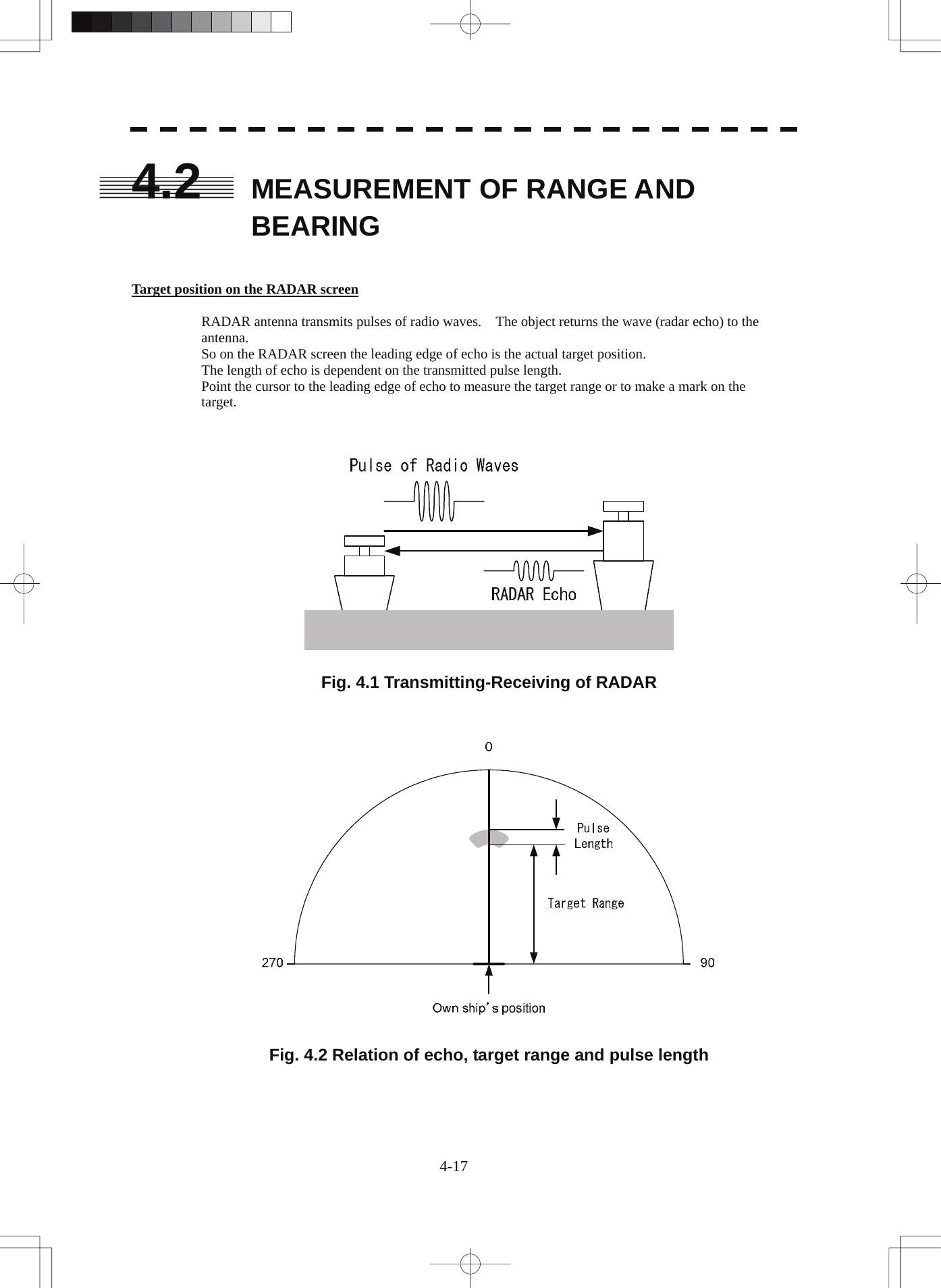
![4-18 4.2 Measurement of Range and Bearing yyyy4 4.2.1 Measurement with Cursor Position (Cursor) Procedures 1 Make sure of the target echoes on the radar display. 2 Move the cursor to the target. The bearing and range of the target will be shown in the Cursor bearing / range (upper right of the display on page 2-3). The range is a distance from the own ship's position. Target Cursor45.0°1800 90270 6.00NMBearing and range from theown ship’s position to target in this figure:True bearing 45.0 °Range 6.00 NMOwn ship’s position To set a cursor bearing numeric value mode Determine whether to display a cursor bearing in true or relative bearing mode. Procedures 1 Put the cursor on the Cursor bearing numeric value indication true / relative switching (upper right of the display ④ on page 2-19), and press the [ENT] key. The selected mode is switched as shown below each time the [ENT] key is pressed. T ⇒ R ⇒ T T :Cursor bearing is displayed in true bearing mode. R :Cursor bearing is displayed in relative bearing mode.](https://usermanual.wiki/Japan-Radio/NKE3710.User-Manual-3/User-Guide-2120533-Page-19.png)
![4-19 4.2.2 Measurement with Electronic Bearing Line and Variable Range Marker [EBL] [VRM] Procedures 1 Press the [EBL1] key. The display in the EBL1 adjustment (upper right of the display ⑤ on page 2-19) will be highlighted, and EBL1 will be shown with a dotted line on the PPI display. 2 Move the EBL1 to the target by turning the [EBL] dial. The EBL1 bearing will be shown in the EBL1 bearing (upper right of the display on page 2-3). The EBL1 bearing is the bearing of the target. 3 Press the [VRM1] key. The display in the VRM1 adjustment (upper right of the display ⑥ on page 2-19) will be highlighted, and VRM1 will be shown with a dotted line on the PPI display. 4 Move the VRM1 to the target by turning the [VRM] dial. The range of VRM1 from the own ship's position will be shown in the VRM1 range (upper right of the display on page 2-3).](https://usermanual.wiki/Japan-Radio/NKE3710.User-Manual-3/User-Guide-2120533-Page-20.png)
![4-20 4.2 Measurement of Range and Bearing yyyy4 4.2.3 Measurement with Two Arbitrary Points Procedures 1 Press the [EBL2] key. The display in the EBL2 adjustment (upper right of the display ⑦ on page 2-19) will be highlighted, and EBL2 will be shown on the PPI display. 2 Press the [EBL] dial to select C for the EBL2 starting point mode switching (upper right of the display ⑫ on page 2-19). 3 Put the cursor on the point A of the two points between which measurement is made, and press the [ENT] key. Refer to the figure below. 4 Move the EBL2 to the other point B by turning the [EBL] dial. Refer to the figure below. 5 Press the [VRM2] key. When VRM2 is selected, ● (intersection marker) will appear on the dotted line of EBL2. 6 Move the intersection marker on the dotted line to point B by turning the [VRM] dial. The range and bearing between the two points will be shown in the VRM2 range and EBL2 bearing (upper right of display on page 2-3). Similarly, EBL1 can also be used for measuring the bearing and range between two points. In this case, perform the above procedure reading EBL2 as EBL1 and VRM2 as VRM1.](https://usermanual.wiki/Japan-Radio/NKE3710.User-Manual-3/User-Guide-2120533-Page-21.png)
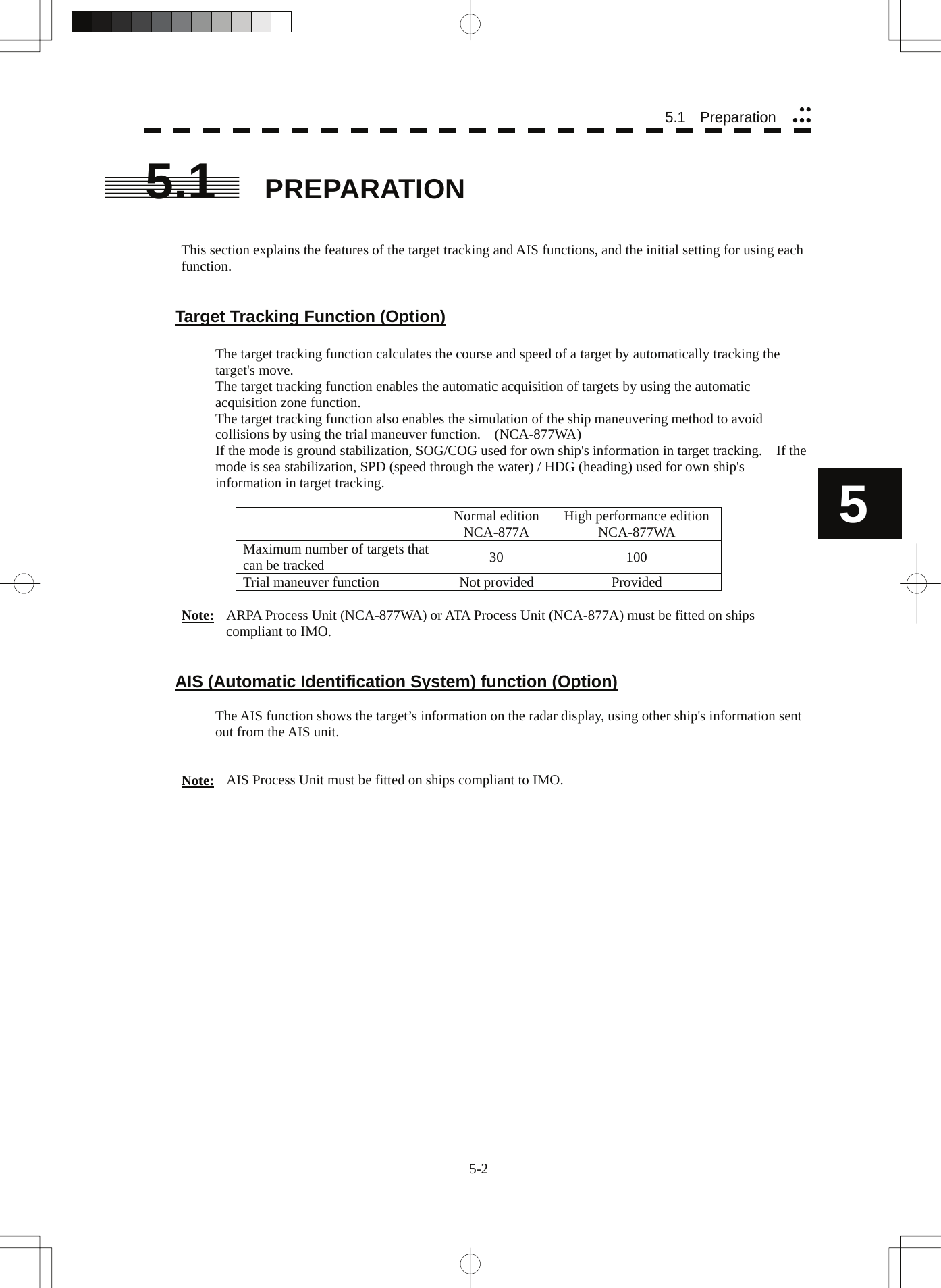
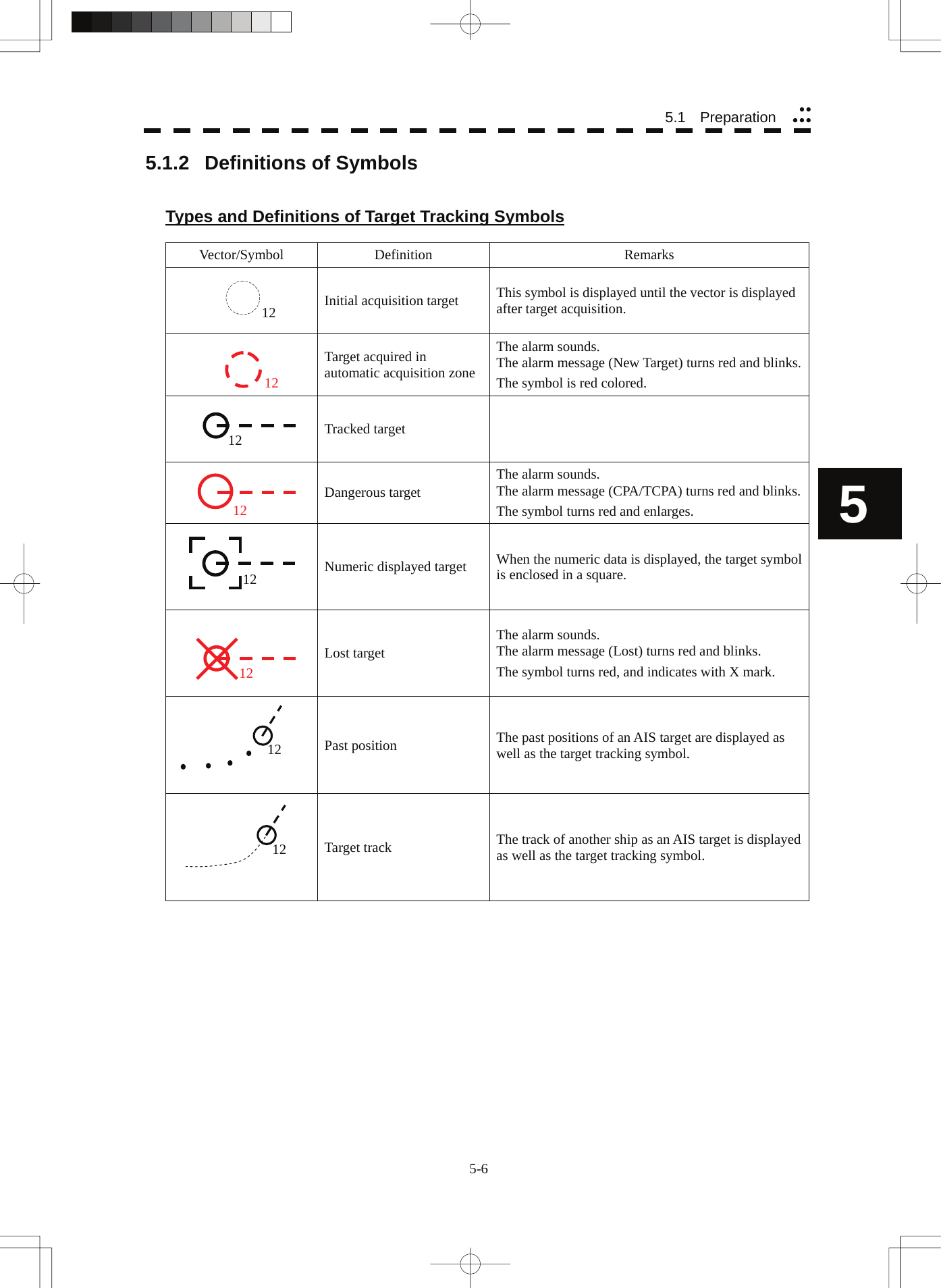
![5-1 z There are the following limitations on use of the target acquisition and target tracking functions. [I] Resolution between adjacent targets and swapping during automatic target tracking Depending on the particular distance and echo size, resolution between adjacent targets during automatic target tracking usually ranges somewhere between 0.03 to 0.05 NM. If multiple targets approach each other, resolution will become about 0.05 NM and this may cause the system to regard them as one target and thus to swap them or lose part of them. Such swapping or less of targets may also occur if the picture of the target being tracked is affected by rain/snow clutter returns or sea clutter returns or moves very close to land. [II] Intensity of echoes and the target tracking function The intensity of echoes and the tracking function have a correlationship, and thus the target will be lost if no echoes are detected during six scans in succession. If a lost target exists, therefore, radar gain must be increased to support detection of the target. If, however, radar gain is increased too significantly, sea clutter returns or other noise may be erroneously detected and tracked as a target, and resultingly, a false alarm may be issued. [III] Adverse effects of error sources on automatic tracking To execute accurate tracking, it becomes necessary first to appropriately adjust the [GAIN], [SEA] and [RAIN] dials of the radar so that the target to be acquired and tracked id clearly displayed on the radar display. Inappropriate settings of these adjustments reduce the reliability / accuracy of automatic tracking. USAGE OF TARGET TRACKING FUNCTION Attention](https://usermanual.wiki/Japan-Radio/NKE3710.User-Manual-3/User-Guide-2120533-Page-24.png)
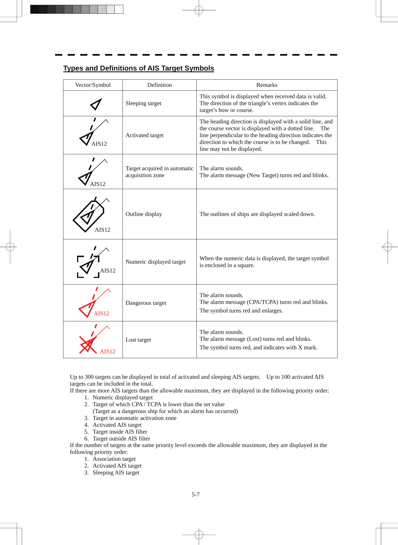
![5-8 5.1 Preparation yyyyy5 The vector of an AIS target is to be displayed with a vector over ground or over water, depending on the speed sensor setting and current offset setting. The type of the currently displayed vector can be confirmed by viewing the setting of the stable mode. When GND is displayed for the stability mode (upper left of the display on page 2-2): Vector over ground When Sea is displayed for the stability mode (upper left of the display on page 2-2): Vector over water When the vector of an AIS target is displayed with a vector over water, the system has converted the AIS target's vector over ground to the vector over water according to the data received from the AIS and the own ship's information. Note: When the AIS target's symbol is activated but the vector is not displayed, the following are probable causes of the trouble: COG/SOG is not yet input from the GPS. The selected speed sensor is malfunctioning. Types and Definitions of Association Target Symbols When a tracked target and an AIS target are decided as identical, it is displayed with either of the following symbols: Vector/Symbol Definition Remarks Priority for tracked targetAssociation target Priority for AIS target Association target Setting of Tracked Target Symbol Display This function switches the tracking target symbol display between on and off. Even if the tracking target symbol display is turned off, the data is retained. Procedures 1 Move the cursor onto the tracking target symbol display On / Off (TT / AIS information ⑨ on page 2-23), and press the [ENT] key. The tracking target symbol display will be set to on or off. Setting of AIS Target Symbol Display This function switches the AIS target symbol display between on and off. Procedures 1 Move the cursor onto the AIS target symbol display On / Off (TT/AIS information ⑩ on page 2-23), and press the [ENT] key. The AIS target symbol display will be set to on or off. AIS12 12](https://usermanual.wiki/Japan-Radio/NKE3710.User-Manual-3/User-Guide-2120533-Page-31.png)
![5-9 5.1.3 Radar Display Vector Display A vector to represent a target’s predicted position can be presented in the True vector or Relative vector mode. In each mode, a vector length can be freely changed for a time interval of 1 to 60 minutes. To switch between the true vector mode and relative vector mode, press the [VECT R/T] key. [I] Vector Mode Selection True Vector Mode In the true vector mode, the direction of a target vector indicates the true course of the target and its vector length is proportional to its speed. In this mode, own ship’s vector is displayed as shown below. In this mode, the movements of other ships around own ship can be accurately and easily monitored. However, CPA Ring cannot appear in this mode. The relative vector isnot displayedTrue vectorOwn ship’s position HL](https://usermanual.wiki/Japan-Radio/NKE3710.User-Manual-3/User-Guide-2120533-Page-32.png)
![5-10 5.1 Preparation yyyyy5 Relative Vector Mode The relative vector does not represent the true motion of the target, but its relative relation with own ship. This means that a target with its relative vector directed to own ship (passing through the CPA Limit ring) will be a dangerous target. In the Relative Vector mode, it can be seen at a glance where the CPA Limit of the dangerous target is. The true vector isnot displayedRelative vectorCPA ringHL Therefore, the True / Relative mode shall optionally be used for the purpose of observation: the True vector mode for grasping the true aspect of a target, and the Relative vector mode for grasping a target’s closest point of approach (CPA). [II] Vector Length (Vector Time) The vector length of a target is proportional to its speed, and the vector time can be switched in a range of 1 to 60 minutes. The diagram below illustrates a vector length of a target for 6 minutes, and the tip of the vector represents the target’s position expected to reach 6 minutes later. Current positionFuture predicted position(6 min later in this example)HL Refer to Section 5.1.7 Setting Vectors for how to change the vector time.](https://usermanual.wiki/Japan-Radio/NKE3710.User-Manual-3/User-Guide-2120533-Page-33.png)
![5-11 5.1.4 Cursor Modes (Cursor) Types and Functions of Cursor Modes The types of cursor modes are listed in the table below. To use the function of a cursor mode, move the cursor onto the PPI object and press the [ENT] key. Mode Function ACQ TT Enables the target tracking function to acquire a target in manual mode. ACT AIS Activates AIS targets, and sets a point filter. TGT Data Displays the numeric data of a tracked target or AIS target. CNCL TT Cancels a target tracking. DEACT AIS Deactivates AIS target. CNCL Data Hides the displayed numeric data of a tracked target or AIS target. Mark Puts a temporary mark. Property Displays the information of tracked targets, AIS targets, and marks. AUTO Changes operation in accordance with the object at the cursor position. Change of Cursor Mode Procedures 1 Move the cursor to the cursor mode Cursor (upper right of the display ① on page 2-19), and press the [ENT] key. On the PPI, press the [CLR / INFO] key and select a desired cursor mode from the list. The selected cursor mode will be shown at the cursor mode (upper right of the display on page 2-3). Note: If the function of a selected cursor mode is not used for one minute or more, the cursor mode is automatically changed to AUTO .](https://usermanual.wiki/Japan-Radio/NKE3710.User-Manual-3/User-Guide-2120533-Page-34.png)
![5-12 5.1 Preparation yyyyy5 Operation of AUTO Mode As shown below, the AUTO mode performs operation in accordance with the object at the cursor position when the [ENT] key is pressed. Object at Cursor Position Operation None Acquires a target. EBL Performs EBL operation. VRM Performs VRM operation. Intersection point of EBL and VRM Performs EBL operation and VRM operation at the same time. Parallel index line (PI) Operates the parallel index line. Tracked target Displays the numeric data of the tracked target. Tracked target with numeric data displayed Hides the numeric data. Sleeping AIS target Activates the AIS target. Activated AIS target Displays the AIS target information. AIS target with numeric data displayed Hides the AIS target information. Automatic acquisition / activation zone Operates the automatic acquisition / activation zone. Sector radar alarm zone Operates the sector radar alarm zone. AIS filter zone Operates the AIS filter zone.](https://usermanual.wiki/Japan-Radio/NKE3710.User-Manual-3/User-Guide-2120533-Page-35.png)
![5-13 z Set the optimum values of collision decision conditions, depending upon vessel type, water area, weather and oceanographic conditions. (For the relations between those conditions and alarms, refer to section 5.5 Alarm Display. ) 5.1.5 Setting Collision Decision Criteria Input of CPA Limit Procedures 1 Move the cursor to the CPA limit setting (TT/AIS information ③ on page 2-23), and press the [ENT] key. The CPA Limit value input screen will appear. 2 Enter the value to be set as a CPA limit. For inputs to the value input screen, refer to Section 3.3.4. Input of TCPA Limit Procedures 1 Move the cursor to the TCPA limit setting (TT/AIS information ④ on page 2-23), and press the [ENT] key. The TCPA Limit value input screen will appear. 2 Enter the value to be set as a TCPA limit. For inputs to the value input screen, refer to Section 3.3.4. 5.1.6 Setting CPA Ring While the distance of the specified CPA Limit value is used as the radius, the CPA ring is displayed with a red circle. Procedures 1 Move the cursor to the CPA ring display On / Off (lower right of the display ⑦ on page 2-21), and press the [ENT] key. The CPA ring will be displayed. Note: The CPA ring is not displayed when the true vector mode is selected. Attention](https://usermanual.wiki/Japan-Radio/NKE3710.User-Manual-3/User-Guide-2120533-Page-36.png)
![5-14 5.1 Preparation yyyyy5 5.1.7 Setting Vectors (Vector Time) Vector time can be set in minutes in the range 1 to 60 min. A true vector mode or relative vector mode can be selected. Setting vector time on the display Procedures 1 Move the cursor to the target vector time setting (TT / AIS information ② on page 2-23), and press the [ENT] key. The Vector Time value input screen will appear. 2 Enter the value to be set as vector time. For how to input numeric data on the numeric value input screen, see Section 3.3.4. Setting vector time using the multi-dial [MULTI] Procedures 1 Press the [MULTI] dial several times to activate the Vector mode. Vector will be displayed in the multi-dial mode (lower left of the display on page 2-3). 2 Turn the [MULTI] dial to set the vector time. Setting vector mode [VECT R / T] Procedures 1 Press the [VECT R / T] key. The current vector mode T (true vector) or R (relative vector) will be displayed in the target vector display true / relative switching (TT / AIS information ① on page 2-23).](https://usermanual.wiki/Japan-Radio/NKE3710.User-Manual-3/User-Guide-2120533-Page-37.png)
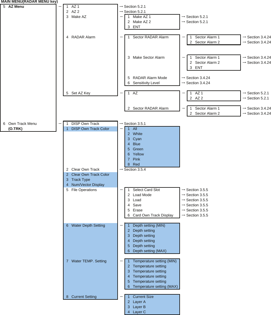
![5-17 5.2.1 Acquiring Target [ACQ] Target acquisition can be performed on two modes, Automatic and Manual, and both modes can be used at the same time. Automatic acquisition Note: If the number of targets being tracked has reached the allowable maximum and other targets (not being tracked) go into the acquisition/activation zone, automatically acquired targets are canceled in ascending order of danger. The position of the scanner shall be at the centre of the azimuth or range in the acquisition/activation zone. Turning On / Off the automatic acquisition and AIS activation (AZ Menu) Procedures 1 Press the [AZ] key for two seconds. The AZ Menu will appear. 2 Press the [1] or [2] key. The acquisition / activation zone 1 (AZ1) or acquisition / activation zone 2 (AZ2) will be set to on or off. On :The acquisition / activation zone is turned on. The mark " " and target ID number are put to an acquired target and move with the target. The vectors are displayed within 1 minute. AIS targets are activated. Off :The acquisition/activation zone is turned off. The acquisition/activation zone will disappear from the radar display, but the system continues to track the acquired target. The activated AIS targets remain activate.](https://usermanual.wiki/Japan-Radio/NKE3710.User-Manual-3/User-Guide-2120533-Page-40.png)
![5-18 5.2 Target Tracking Operation yyyyy5 Creating the automatic acquisition and AIS activation Zone Procedures 1 Press the [AZ] key for 2 seconds. The AZ Menu will appear. 2 Open the Make AZ menu by performing the following menu operation. 3. Make AZ 3 Press [1] or [2] key. The range setting of the acquisition / activation zone 1 (AZ1) or acquisition / activation zone 2 (AZ2) will be started. 4 Set the starting azimuth and range by turning the [EBL] dial and [VRM] dial, and press the [ENT] key. 5 Set the ending azimuth and range by turning the [EBL] dial and [VRM] dial, and press the [ENT] key. The acquisition / activation zone will be determined. Setting the [AZ] key allocation (Set AZ Key) A generally used acquisition / activation zone can be turned on / off by simply pressing the [AZ] key. Procedures 1 Press the [AZ] key for 2 seconds. The AZ Menu will appear. 2 Open the AZ menu by performing the following menu operation. 5. Set AZ Key → 1. AZ 3 Set the assignment of the key. On :Pressing the [AZ] key turns on / off the acquisition / activation zone. Off :Pressing the [AZ] key does not turn on the acquisition / activation zone. Note: If the RADAR Alarm key assignment is set, pressing the [AZ] key turns on / off the Acquisition Zone at the same time the RADAR Alarm is turned on / off.](https://usermanual.wiki/Japan-Radio/NKE3710.User-Manual-3/User-Guide-2120533-Page-41.png)
![5-19 Manual Acquisition [ACQ] Note: If more targets are acquired manually in the condition that the maximum number of targets are under tracking, the targets cannot acquired. Procedures 1 Move the cursor onto the target to be acquired, and press the [ACQ] key. The target will be acquired and the initial acquisition symbol will be displayed. The vector will be displayed within one minute. Target manually acquired.The initial acquisition symbol is displayed.Target that has passed for 1 min.The acquisition symbol and vector are displayed. To perform operation only in the manual acquisition mode without automatic acquisition/activation, turn off the automatic acquisition/activation function. Use of Automatic and Manual Acquisition Modes Use the manual acquisition mode while the automatic acquisition mode is on. Manually acquire the target to which particular attention should be paid, and get the other targets automatically acquired. If a new target appears exceeding the maximum number of targets, the manually acquired target is displayed even in the background until it gets out of the display. However, automatically acquired targets are canceled starting far distance from own ship.](https://usermanual.wiki/Japan-Radio/NKE3710.User-Manual-3/User-Guide-2120533-Page-42.png)
![5-20 5.2 Target Tracking Operation yyyyy5 5.2.2 Canceling Unwanted Tracked Targets [TGT CNCL] Unwanted tracked targets can be canceled one by one in the following cases: • Tracking is no longer necessary for targets with which vectors/symbols are displayed after being acquired and tracked. • The number of vectors on the radar display needs to be reduced for easy observation. When targets are to be re-acquired from the beginning, all the current vectors can also be canceled. Canceling targets one by one [TGT CNCL] Procedures 1 Put the cursor on the tracked target to the desired for canceling target, and press the [TGT CNCL] key. The vectors and symbols of the tracked targets will disappear, and only the radar video remain. Canceling all targets collectively [TGT CNCL] Procedures 1 Press the [TGT CNCL] key for 5 seconds. The vectors and symbols of all the targets will disappear, and only the radar videos remain. Note: When all the targets have been canceled, the system stops tracking them. Thus, you need to re-acquire targets in manual or automatic acquisition mode. Do not cancel all the targets unless otherwise required.](https://usermanual.wiki/Japan-Radio/NKE3710.User-Manual-3/User-Guide-2120533-Page-43.png)
![5-21 z When a target or own ship changes its course, or when a new target is acquired, its vector may not reach a given level of accuracy until 3 minutes or more has passed after such course change or target acquisition. Even if 3 minutes or more has passed, the vector may include an error depending upon the tracking conditions. 5.2.3 Tracked Target Data Display [TGT DATA] Type of Data Display (Target Information) Target Data Target identification (TT ID) ID number of the target True bearing (BRG) 0.1° unit Range 0.01 NM unit Course 0.1° unit Speed 0.1 knot unit Closest point of approach (CPA) 0.01 NM unit Time to CPA (TCPA) 0.1 min unit Bow crossing range (BCR) 0.01 NM unit Bow crossing time (BCT) 0.1 min unit The target for which its numeric data is displayed is marked with a symbol " " to distinguish from other targets. If a target’s data is displayed, but without the symbol " " , such a target exists outside the currently displayed radar display. Method of Displaying Numeric Data [TGT DATA] Procedures 1 Put the cursor on the tracked target for which numeric data is to be displayed, and press the [TGT DATA] key. Then, the data of the designated target will appear, it will be marked with a symbol " ". The target data will remain on the radar display until the target is lost and its vector disappears, or until another target is designated. If a target with the mark " " is designated, only its true bearing and range will appear until its vector appears. Attention](https://usermanual.wiki/Japan-Radio/NKE3710.User-Manual-3/User-Guide-2120533-Page-44.png)
![5-22 5.2 Target Tracking Operation yyyyy5 Cancellation of Numeric Data Display (CNCL Data) Procedures 1 Put the cursor on the tracked target with which numeric data is displayed, and press the [CLR / INFO] key. The cursor mode list will appear. 2 Press the [6] key. The numeric value will disappear. 5.2.4 Displaying Target ID No. (Target Number Display) A target ID number is a value displayed beside the acquisition symbol when a target is acquired. A target ID number 1 to 100 is assigned to each target in acquisition order. Once a target ID number is assigned, it identifies the target until the target is lost or the target acquisition is canceled. Procedures 1 Press the [TT MENU] key. 2 Press the [4] key. Target Number Display will appear. 3 Press the [numeric] key corresponding to the display method to be set. On :Displays target ID numbers. Off :Hides target ID numbers. Target Track :Displays target ID number with target track. If there are many tracking targets and their symbol display is confusing, set Target Number Display to off to view the radar display easily. Note: An ID number is always displayed for only targets with which numeric data is displayed.](https://usermanual.wiki/Japan-Radio/NKE3710.User-Manual-3/User-Guide-2120533-Page-45.png)
![5-23 5.2.5 Adding Tracked Target ID Name (Name) The system can enter a name for each of tracking targets that have been acquired. Procedures 1 Put the cursor on the tracked target, and press the [CLR / INFO] key. The cursor mode list will appear. 2 Press the [8] key. The TT Target Information will appear. 3 Press the [1] key. The setting items for ship name (Name) will be displayed. 4 Select the input method. Data Base : Selection of one of previously input ship names. When this method is selected, a list of ship names that have been input by selecting Input will be displayed. Input : Input of a new ship name. When this method is selected, the ship name (Name) input window will open. Off : Target ship's name is not displayed. Entering a new ship name (Input) 5 Input a new ship name. Up to 8 characters can be input as a ship name. For the input method on the character input screen, see Section 3.3.4. The input name by selecting Input is saved in Data Base . Selecting one of previously input ship names (Data Base) 5 Press the [numeric] key corresponding to the ship name to be selected. The selected ship name will be entered. * Data Base can contain 30 ship names.](https://usermanual.wiki/Japan-Radio/NKE3710.User-Manual-3/User-Guide-2120533-Page-46.png)
![5-25 Procedures 1 Tracking a target for which ground fixed. 2 Put the cursor on the tracked target, and press the [CLR / INFO] key. The cursor mode list will appear. 3 Press the [8] key. The Property will appear. 4 Press the [3] key. The reference target function will be set to on or off. On :A reference target is set. Off :The reference target is canceled. 5 Put the cursor on the speed sensor switching (Own ship information ② on page 2-22), press the [ENT] key, and select REF. . The speed of own ship calculated from the reference target will be displayed. When a reference target is set, the symbol display is changed to " R ". Only one target can be set as a reference target. When a new reference target is set, the previously set reference target is canceled. Note: If AIS function is set to on, the reference target function cannot be used.](https://usermanual.wiki/Japan-Radio/NKE3710.User-Manual-3/User-Guide-2120533-Page-48.png)
![5-26 5.2 Target Tracking Operation yyyyy5 5.2.7 Operation Test (TT Test Menu) CAUTION Target Tracking Function Test is provided to test if the target tracking function is operating normally. Thus, do not use the function except when you test the target tracking function. In particular, if the operation test mode is used during navigation, pseudo targets appear on the radar display and they are confused with actual targets. Do not use the mode during navigation. Otherwise, an accident may result. The following functions are available for testing the target tracking function: [I] Test Video Makes an operation check on the target detection circuit. [II] TT Simulator Generates pseudo targets on the radar display in order to test if the target tracking function is operating normally. [III] Status Displays the status of the target tracking function. [IV] Gate Display Displays the gate size for acquiring / tracking a target.](https://usermanual.wiki/Japan-Radio/NKE3710.User-Manual-3/User-Guide-2120533-Page-49.png)
![5-27 [I] Test Video Test Video is used to check whether the video signals under target acquisition and tracking are inputted to and processed in the target detection circuit normally. However, it is sufficient to check that VDH in Test Video is displayed. Note: Test Video may not be displayed for a target which is not yet acquired or tracked. Test Video may not be displayed either if the [GAIN] dial or [SEA] dial is not properly adjusted. Procedures 1 Press the [TT MENU] key. 2 Open the TT Test Menu by performing the following menu operation. 9. TT Test Menu 3 Press the [1] key. The setting items for Test Video will be displayed. 4 Select the test video to be displayed. In general, VDH is sufficient for target display checks in test video mode. If any target displayed clearly in the radar display is not displayed in the Test Video mode, the target detection circuit of the Target Tracking unit may have a trouble Cancellation 1 Press the [1] key while the TT Test Menu is displayed. The setting items for Test Video will be displayed. 2 Press the [1] key The test video display will be turned off.](https://usermanual.wiki/Japan-Radio/NKE3710.User-Manual-3/User-Guide-2120533-Page-50.png)
![5-28 5.2 Target Tracking Operation yyyyy5 [II] Target Tracking Simulator Pseudo targets can be generated in certain known positions to check whether the target tracking units are operating normally. Since the pseudo targets move depending on known parameters, the values for these pseudo targets can be compared with the known value if the pseudo targets are acquired and tracked, and displayed. Thus, it can be checked if the system is operating normally. Procedures 1 Press the [STBY] key. The equipment will enter the transmission standby state. 2 Press the [TT MENU] key. 3 Open the TT Test Menu by performing the following menu operation. 9. TT Test Menu 4 Press the [2] key. The setting items for TT Simulator will be displayed. 5 Select the scenario to be set. The TT Simulator display will be turned on. 6 Press the [TX / PRF] key. When the TT simulator is active, the character " X " will display at the bottom of the radar display. Target tracking simulator / scenario Target start point Target end point Scenario Distance Bearing Distance Bearing Pseudo-target speed 1 3.2 nm 20 ° 1 nm 90 ° 20 kn 2 6 nm 0 ° 0 nm 0 ° 10 kn 3 6 nm every 18 °1 nm every 18 °10 kn 4 6 nm 45 ° 1 nm 45 ° 105 kn 5 6 nm 45 ° 6 nm 150 ° 20 kn 6 6 nm 45 ° 6 nm 150 ° 20 kn Note: When the simulator is operating, set 0 ° as the heading bearing, and 0 kn as the speed of own ship. When the range between own ship and the pseudo target is 0, the target will disappear. Cancellation 1 Press the [STBY] key. The equipment will enter the transmission standby state. 2 Press the [2] key while the TT Test Menu is displayed. The setting items for TT Simulator will be displayed. 3 Press the [1] key. The TT Simulator display will be turned off.](https://usermanual.wiki/Japan-Radio/NKE3710.User-Manual-3/User-Guide-2120533-Page-51.png)
![5-29 [III] Status display (Status) The current Target Tracking status will appear. Procedures 1 Press the [TT MENU] key. 2 Open the TT Test Menu by performing the following menu operation. 9. TT Test Menu 3 Press the [3] key. The setting items for Status will be displayed. *Constant : Vector response *VID Level TD : Threshold value used for automatic acquisition *VID Level High : Threshold value used for tracking *VID Level Low : Unused *Gate Size : Size of gate used for tracking *Tracking : Number of targets currently acquired](https://usermanual.wiki/Japan-Radio/NKE3710.User-Manual-3/User-Guide-2120533-Page-52.png)
![5-30 5.2 Target Tracking Operation yyyyy5 [IV] Gate Display The gate displays an area monitoring a target using the Target Tracking function. This radar equipment allows the gate size to change automatically according to target range and size. User can check the gate size using the following function. Procedures 1 Press the [TT MENU] key. 2 Open the TT Test Menu by performing the following menu operation. 9. TT Test Menu 3 Press the [4] key. The gate display mode is switched. On : Gate is displayed Off : Gate is not displayed 4 Display the numeric value of a target according to Section 5.2.3. The numeric value of the target will be displayed, and the tracked target symbol will be enclosed in a green gate. Note: The Target Tracking can display the gate of two targets simultaneously.](https://usermanual.wiki/Japan-Radio/NKE3710.User-Manual-3/User-Guide-2120533-Page-53.png)
![5-31 z When the AIS function is set to Off, the AIS display function is turned off and AIS symbols are no longer displayed. z Once the AIS display function is set to Off, it is not automatically switched to On even if a dangerous target exists. 5.3 AIS OPERATION 5.3.1 Restrictions The following restrictions are placed on use of the AIS function. • The AIS function is unavailable in the following cases: a) MAN or REF. is selected for the speed sensor. b) The current offset (Set/Drift Setting) is set while LOG or 2AXW is selected for the speed sensor. c) The GPS geodetic system is used except WGS-84. • LOG or 2AXW cannot be selected for the speed sensor in the following case: The AIS function is turned on and the current offset (Set/Drift Setting) is selected. • MAN cannot be selected for the speed sensor in the following case: The AIS function is On. • Current offset (Set/Drift Setting) cannot be turned On in the following case: LOG or 2AXW is selected for the speed sensor while the AIS function is on. 5.3.2 Setting AIS Display Function (AIS Function) Procedures 1 Put the cursor on the AIS On / Off (TT / AIS information ⑧ on page 2-23), and press the [ENT] key. The received AIS information will be shown on the radar display. Attention](https://usermanual.wiki/Japan-Radio/NKE3710.User-Manual-3/User-Guide-2120533-Page-54.png)
![5-32 5.3 AIS Operation yyyyy5 5.3.3 Activate AIS Targets (Activate AIS) Activate an AIS target, and display the target’s vector and make a collision decision. Manual activation (ACT AIS) Activate an AIS target in manual mode to display the vector and heading line. Procedures 1 Put the cursor on the AIS symbol to be activated, and press the [CLR/INFO] key. The setting items for cursor modes will be displayed. 2 Press the [2] key. The selected AIS target will be activated. Automatic activation (AUTO Activate) Activate an AIS target in automatic mode to display the vector and heading line. When the automatic activation function is used, AIS targets are automatically activated when they go into the automatic activation zone. The automatic activation zone is identical to the automatic acquisition zone (AZ) used for target tracking. For the zone setting, refer to " Acquiring Target " in Section 5.2.1 The position of the scanner shall be at the centre of the azimuth or range in the acquisition/activation zone. If there are more AIS targets than the allowable maximum, they are deactivated in the low-priority (See the section 5.1.2). Reference If an AIS target is activated but the vector is not displayed, refer to " Displaying Target ID Number " in section 5.3.6 5.3.4 Deactivate AIS Targets (Deactivate AIS) Deactivate an AIS target and clear the display of the vector and heading line. Procedures 1 Put the cursor on the AIS target to be deactivated, and press the [CLR/INFO] key. The setting items for cursor modes will be displayed. 2 Press the [5] key. The selected AIS target will be deactivated. Note: This operation is available only for an activated AIS target.](https://usermanual.wiki/Japan-Radio/NKE3710.User-Manual-3/User-Guide-2120533-Page-55.png)
![5-33 5.3.5 Displaying AIS Information [TGT DATA] Types of information displayed There are two modes (simple and detail) to display AIS target information. The display items are determined by the selected mode. Display Item Detail mode Simple mode NAME (ship name) Up to 20 characters Call Sign Up to 7 characters MMSI Up to 9 characters COG (course over ground) or CTW (course through water) 0.1 ° unit SOG (speed over ground) or STW (speed through water) 0.1 knot unit CPA (closest point of approach) 0.01 nm unit TCPA (time to CPA) 0.1 min unit BRG (true bearing) 0.1 ° unit Range 0.01 nm unit HDG (heading bearing) 0.1 ° unit ROT (rate of turn) 0.01 °/min POSN (latitude / longitude) 0.0001’ unit Destination (waypoint) Up to 20 characters NAV Status Status (number) Not displayed If the numeric information of ROT is blank, the radar is receiving the AIS data which is cannot displayed. In this case, you can only trust the turning direction which is indicated by the turn indicator. The turn indicator is displayed on the AIS symbol as the line perpendicular to the heading direction. (See the Section 5.1.2 "Types and Definitions of AIS Target Symbols") If the numeric information of SOG or STW is 102.2kn, the target ship's speed is 102.2kn or over. Then the system cannot calculate CPA and TCPA. Therefore, missing is indicated in the CPA and TCPA information. The detail mode displays the numeric data of only a single ship, the simple mode can display the numeric data of up to two ships. For NAV Status, one of the following statuses is displayed in accordance with Navigation Status: No. Status 0 Under Way Using Engine 1 at Anchor 2 Not Under Command 3 Restricted Maneuverability 4 Constrained by Her Draft 5 Moored 6 Aground 7 Engaged in Fishing 8 Under Way Sailing 9 Reserved 10 Reserved 11-14 Reserved 15 Not Defined](https://usermanual.wiki/Japan-Radio/NKE3710.User-Manual-3/User-Guide-2120533-Page-56.png)
![5-34 5.3 AIS Operation yyyyy5 Displaying AIS Target Information [TGT DATA] Procedures 1 Put the cursor on the AIS target of which information is to be displayed , and press the [TGT DATA] key. The information of the selected AIS target will be displayed. Reference: When the numeric data of a target is displayed but the mark " " is not on the radar display, the target is outside the display. Canceling AIS Target Information Display (CNCL Data) Procedures 1 Put the cursor on the activated AIS target of which information display is to be cancelled, and press the [CLR / INFO] key. The setting items for cursor modes will be displayed. 2 Press the [6] key. The information display of the selected AIS target will be cleared. Selecting Detail / Simple Mode for AIS Target Information Display Procedures 1 Put the cursor on the detail/simple display switching (AIS target information ① on page 2-25), and press the [ENT] key. The detail or simple mode display for AIS target information will be selected.](https://usermanual.wiki/Japan-Radio/NKE3710.User-Manual-3/User-Guide-2120533-Page-57.png)
![5-35 Message Received AIS messages can be displayed. Up to 10 messages of addressed message and up to 10 messages of broadcast message can be displayed. If the number of messages exceeds 10, the oldest received messages are sequentially deleted. Displaying Message Selected from List (Message) Procedures 1 Press the [RADAR MENU] key twice. 2 Open the Message menu by performing the following menu operation. 7. AIS Menu → 7. Message 3 Press the [1] or [2] key. Pressing [1] key lists addressed messages; pressing [2] key lists broadcast messages. Each list shows ship names and message-received time. For an unread message, * is displayed to the left of the item number. 4 Press the [numeric] key corresponding to the message to be displayed. The message will appear. Displaying Specified Target's Message Procedures 1 Display AIS target information. If there are messages from the target, a message mark will be displayed in the unread message display field (AIS target information ② on page 2-25). 2 Put the cursor on the unread message display (AIS target information in ② on page 2-25), and press the [ENT] key. The message will appear. Deleting Message (Delete) Procedures 1 Press the [1] key while the message is displayed. The Confirmation Window will appear. 2 Press the [1] key. The message will be deleted, and the ship name and message-received time will disappear from the list.](https://usermanual.wiki/Japan-Radio/NKE3710.User-Manual-3/User-Guide-2120533-Page-58.png)
![5-36 5.3 AIS Operation yyyyy5 Displaying Data of Lost AIS Target (Display Lost TGT Data) The data of the last-lost AIS target can be displayed. The data of only one target that has been lost most recently can be displayed. Procedures 1 Press the [RADAR MENU] key twice. 2 Open the Display Lost Target Data menu by performing the following menu operation. 7. AIS Menu → 8. Display Lost TGT Data The data of the last-lost AIS target will be displayed. Displaying Own Ship's AIS Data (Own Ship's AIS Data) The AIS data of own ship can be displayed. Procedures 1 Press the [RADAR MENU] key twice. 2 Open the Own Ship's AIS Data menu by performing the following menu operation. 7. AIS Menu → 9. Own Ship’s AIS Data The own ship's AIS data will be displayed.](https://usermanual.wiki/Japan-Radio/NKE3710.User-Manual-3/User-Guide-2120533-Page-59.png)
![5-37 5.3.6 Displaying Target ID No. (Target Number Display) When an AIS target is activated, a target ID number is displayed next to the AIS target symbol. A target ID number 1 to 100 is assigned to each target in activation order. Once a target ID number is assigned, it identifies the target until the target is lost or deactivated. Procedures 1 Press the [RADAR MENU] key twice. 2 Open the Target Number Display menu by performing the following menu operation. 7. AIS Menu → 5. Target Number Display 3 Press the [numeric] key corresponding to the display method to be set. On : Displays target ID numbers. Off : Hides target ID numbers. Target Track : Displays target ID number with AIS track. Ship's Name : Displays the ship's name. If there are many tracking targets and their symbol display is confusing, set Target Number Display to off to view the radar display easily. Note: An ID number or ship's name is always displayed for only targets with which numeric value is displayed. 5.3.7 Setting AIS Filter (AIS Filter Setting) About an AIS filter By setting an AIS filter, an AIS target in the area can be displayed by priority or only the targets in the area can be displayed. An AIS filter is initially set in a circle having a radius of 20 [nm] from the CCRP. If 301 or more AIS targets exist in the filter range, they are displayed in the priority order explained in Section 5.1.2 Symbols - Types and Definitions of AIS Target Symbols. Types of AIS Filters (Filter Type) There are the following 3 types of AIS filters: Range :A filter is set in a circle with a set range as the radius. Sector :A filter is set in a sector formed by two bearings with the bow as reference. Zone :A filter is set in a zone formed by two bearings and two ranges with the bow as reference. Procedures 1 Put the cursor on the AIS filter mode switching (TT / AIS information ⑫ on page 2-23), and press the [ENT] key to select the filter to be set. The AIS filter will be selected.](https://usermanual.wiki/Japan-Radio/NKE3710.User-Manual-3/User-Guide-2120533-Page-60.png)
![5-38 5.3 AIS Operation yyyyy5 Creation of AIS Filter (Make AIS Filter) Procedures 1 Press the [RADAR MENU] key twice. 2 Open the AIS Filter Setting menu by performing the following menu operation. 7. AIS Menu → 4. AIS Filter Setting 3 Press the [2] key. The mode to make an AIS filter will be activated. [I] Setting Range Filter 4 Set a filter range by turning the [VRM] dial, and press the [ENT] key. [II] Setting Sector Filter 4 Set a starting bearing by turning the [EBL] dial, and press the [ENT] key. 5 Set an ending bearing by turning the [EBL] dial, and press the [ENT] key. [III] Setting Zone Filter 4 Set a starting bearing and range by turning the [EBL] dial and [VRM] dial, and press the [ENT] key. 5 Set an ending bearing and range by turning the [EBL] dial and [VRM] dial, and press the [ENT] key. Note: When the automatic activation function is enabled, the filter range is automatically changed for covering the automatic activation zone. Thus, the automatic activation zone is always within the filter range. AIS Filter Display On/Off (Filter Display) Procedures 1 Press the [RADAR MENU] key twice. 2 Open the AIS Filter Setting menu by performing the following menu operation. 7. AIS Menu → 4. AIS Filter Setting 3 Press the [3] key. Filter Display will be set to on or off.](https://usermanual.wiki/Japan-Radio/NKE3710.User-Manual-3/User-Guide-2120533-Page-61.png)
![5-39 Display of Targets outside AIS Filter (Filter Mode) Procedures 1 Press the [RADAR MENU] key twice. 2 Open the Filter Mode menu by performing the following menu operation. 7. AIS Menu → 6. Filter Mode 3 Press the [6] key. The Filter Mode is switched. Display : Displays only AIS targets in the AIS filter. Priority : Displays AIS targets in the AIS filter by priority, and also displays targets outside the AIS filter. Note: Activated AIS targets can be displayed even when they are outside the AIS filter. Point Filter AIS targets which are not displayed because they are outside the AIS filter or at low priority levels can be activated by giving a higher priority to them. Procedures 1 Put the cursor on the position where a point filter is to be set, and press the [CLR / INFO] key to select the filter to be set. The setting items for cursor modes will be displayed. 2 Press the [2] key. A point filter will be set at the cursor position. If an AIS target is in the point filter, it will be activated. When an AIS target is activated or an AIS target is not found within one minute, the point filter will be cleared. Note: The point filter's range is 1 nm, and cannot be changed.](https://usermanual.wiki/Japan-Radio/NKE3710.User-Manual-3/User-Guide-2120533-Page-62.png)
![5-40 5.3 AIS Operation yyyyy5 5.3.8 Conditions for Deciding AIS Target to be Lost About a lost target When the data of an AIS target cannot be received for a specified time, the target is decided to be lost and the target data is deleted. As shown in the table below, the time until target data is deleted varies depending on the class of receive data and the target status. Deciding AIS Target to be Lost Time until data deletion Target status SOLAS ship (Class A) SOLAS ship (Class B) Vessel below 3 knots (Class A) or 2 knots (Class B) and it is now at anchor or on the berth 18 min 18 min Vessel of 3 knots or more and it is now at anchor or on the berth 60 sec 18 min Vessel of 0 to 14 knots (Class B: 0 to 14 knots) 60 sec 180 sec Vessel of 14 to 23 knots 36 sec 180 sec Vessel of 23 knots or more 30 sec 180 sec SAR (Search and Rescue) 60 sec 60 sec ATON (Aid to Navigation) 18 min 18 min Base Station 60 sec 60 sec Reference: When a dangerous target ship is lost, a lost alarm is issued and the symbol changes to a lost symbol. The lost symbol will display continuously on the last-received position. If the [ALARM ACK] key is pressed, the symbol is cleared.](https://usermanual.wiki/Japan-Radio/NKE3710.User-Manual-3/User-Guide-2120533-Page-63.png)
![5-41 5.3.9 Setting Conditions for AIS Alarm (AIS Alarm Setting) Conditions for issuing a Lost alarm and CPA/TCPA alarm for AIS targets can be set. Setting of Condition for Lost Alarm Procedures 1 Press the [RADAR MENU] key twice. 2 Open the AIS Alarm Setting menu by performing the following menu operation. 7. AIS Menu → 6. AIS Alarm Setting 3 Press the [1] key. The setting items for Lost Alarm will be displayed. 4 Press the [numeric] key corresponding to the condition to be set. Off : A lost alarm is not issued. Danger : A lost alarm is issued only for AIS targets for which a dangerous target alarm has been issued. ACT&Danger : A lost alarm is issued only for activated AIS targets and AIS targets for which a dangerous target alarm has been issued. ACT&Danger&Select : A lost alarm is issued only for activated AIS targets, data indicated AIS targets and AIS targets for which a dangerous target alarm has been issued. Note: A lost alarm is not issued for sleeping AIS targets. Setting of Condition for CPA/TCPA Alarm Procedures 1 Press the [RADAR MENU] key twice. 2 Open the AIS Alarm Setting menu by performing the following menu operation. 7. AIS Menu → 6. AIS Alarm Setting 3 Press the [2] key. The setting items for CPA/TCPA Alarm is switched. Off : A CPA/TCPA alarm is not issued. ACT : A CPA/TCPA alarm is issued only for activated AIS targets. ACT&Sleep : A CPA/TCPA alarm is issued for all AIS targets on the radar display. Note: When the Lost Alarm menu set to Off, the CPA ring color changes to dark color.](https://usermanual.wiki/Japan-Radio/NKE3710.User-Manual-3/User-Guide-2120533-Page-64.png)
![5-42 5.4 Decision of Targets as Identical yyyyy5 z Turn off Association in order not to make a decision on if targets are identical, or in order to display symbols that have disappeared. 5.4 DECISION OF TARGETS AS IDENTICAL (ASSOCIATION) CAUTION If a great value is set as a condition for deciding targets as identical, a tracking target near an AIS target is regarded as identical to the AIS target and it may not be displayed any more. For example, when a pilot boat (which is a small target not being tracked) equipped with an AIS function approaches a cargo ship as a tracking target not equipped with an AIS function, the tracking target symbol of the cargo ship may not be displayed any more. Setting of Function to Decide Targets as Identical (Association) When an AIS target and a tracking target are decided to be identical, an association symbol is displayed for the targets regarded as identical. In this case, the AIS target symbol is automatically activated. Procedures 1 Put the cursor on the association On/Off (TT/AIS information ⑪on page 2-23), and press the [ENT] key. Association will be set to on or off. Attention](https://usermanual.wiki/Japan-Radio/NKE3710.User-Manual-3/User-Guide-2120533-Page-65.png)
![5-43 Setting of Conditions for Deciding AIS and Tracked Targets as Identical (Association Setting) Procedures 1 Press the [TT MENU] key. 2 Press the [1] key. The Association Setting menu will appear. 3 Select and enter the item to be set. Conditions for deciding targets as identical will be set. When the differences of all item between AIS and tracked target are under the set conditions.. Once regard as identical, when one of the differences exceed 125 % of the set condition, they are regarded as dissidence. * The setting for this function is common to Association Setting in the AIS Menu. Types of Decision Conditions to be Set Decision conditions 1. Association On / Off (Function to decide targets as identical) 2. Priority AIS / TT (Symbol to be displayed) 3. Bearing 0.0 to 9.9 ° 4. Range 0 to 999 m 5. Course 0 to 99 ° 6. Speed 0 to 99 kn 7.Applicable AIS Target ACT or ACT&Sleep (activated AIS target or all AIS target)](https://usermanual.wiki/Japan-Radio/NKE3710.User-Manual-3/User-Guide-2120533-Page-66.png)
![5-48 5.6 Track Function yyyyy5 5.6 TRACK FUNCTION 5.6.1 Past Position (Past POSN) Procedures 1 Put the cursor on the past position display interval unit switching (TT/AIS information ⑦ on page 2-23), and press the [ENT] key to set a desired unit. The past position display interval unit will be set to min or NM . 2 Put the cursor on the past position display interval switching (TT/AIS information ⑥ on page 2-23), and press the [ENT] key to set a desired track display interval. The past position will be set. Off :Tracks are not displayed. Numeric :Tracks are displayed at intervals of a specified value. The past position function can display up to 10 past positions of a target under tracking. The past position display interval can be set to specified time intervals of 0.5, 1, 2, or 4 minutes, or specified range intervals of 0.1, 0.2, 0.5, or 1 nm. The specified interval is displayed in the past position display interval switching (TT / AIS information ⑥ on page 2-23). When Off is displayed, the track display function is turned off. The track mode operates in conjunction with the vector mode, and a true or relative track is displayed. In relative vector mode, the relative tracks of the target are displayed. In true vector mode, true tracks that are calculated from the relative bearing, range, own ship's course, and speed are displayed. The target is acquisition, past position of traced target is start plot. The AIS target is displayed, past position of AIS target is start plot. If the past position plotted time is short, the indicated past position duration may not have achieved the specified time or range.](https://usermanual.wiki/Japan-Radio/NKE3710.User-Manual-3/User-Guide-2120533-Page-71.png)
![5-49 5.6.2 Target Ship's Tracks (Target Track) This function makes settings for the tracks of tracked targets and AIS targets. The system can display the tracks of up to 20 target ships. [I] Track Color Setting (Target Track Color) Procedures 1 Put the cursor on the tracked target or activated AIS target, and press the [CLR / INFO] key. The setting items for cursor modes will be displayed. 2 Press the [8] key. The TT Target Information will appear. 3 Press the [2] key. The setting items for Track Color will be displayed. 4 Press the [numeric] key corresponding to the track color to be set. Colors set by performing the procedure in [III] Setting of Target Ship's Track Colors can be selected. Individual colors can be set for up to 10 ships. The same color is set for 11 to 20 ships. [II] Target Ship's Track Function On/Off (Target Track Function) Procedures 1 Open the T.TRK menu by performing the following menu operation. T.TRK 2 Press the [1] key. The Target Track Function will be set to on or off. On : Target Track Function is turned on. Off : Target Track Function is turned off. * Note that when this function is turned off, all the other ship's track functions are turned off. In this case, the track data of other ships is not saved, so they cannot be traced later.](https://usermanual.wiki/Japan-Radio/NKE3710.User-Manual-3/User-Guide-2120533-Page-72.png)
![5-50 5.6 Track Function yyyyy5 [III] Setting of Target Ship's Track Colors (Target Track Color) You can set either one track color for all targets under tracking, or individual colors for the ships of track numbers 1 to 10. The tracks of ships 11 to 20 are displayed in the same color. * If the other ship's track function (Target Track Function) is turned off, the track data of other ships is not saved. Procedures 1 Open the Target Track Color menu by performing the following menu operation. T.TRK → 2. Target Track Color 2 Press the [1] key. The setting items for All will be displayed. 3 Press the [numeric] key corresponding to the track display to be set. Individual : Track color is set individually for ships. Color name : One color is set for all ships. Individual setting 4 Press the [numeric] key corresponding to the track number to be set. The setting items for the selected track number will be displayed. 5 Press the [numeric] key corresponding to the track color to be set. The track color of the selected track number will be set. When Individual is selected, the track numbers Target Track No. 1 to No. 10 and the individual setting for Other are valid. Select a color for each target. The color list is displayed by pressing the [numeric] key corresponding to the item number to be set. Select a desired color. There are 8 color choices: Off , White , Cyan , Blue , Green , Yellow , Pink , and Red . Target Track No. 1 to No. 10 : Setting for 1 to 10 ships Other : Setting for 11 to 20 ships * Note that the individual setting is not enabled unless Individual is selected.](https://usermanual.wiki/Japan-Radio/NKE3710.User-Manual-3/User-Guide-2120533-Page-73.png)
![5-51 [IV] Setting of Target Ship's Track Display (Target Track Display) The target track display function can be turned on / off. Choices for track display are displaying / hiding the tracks of all ships and Individual (displaying the tracks of individual ships). Procedures 1 Open the Target Track Display menu by performing the following menu operation. T.TRK → 3. Target Track Display 2 Press the [1] key. The setting items for All will be displayed. 3 Press the [numeric] key corresponding to the track display to be set. Individual : Track display is set for individual ships. Off : The tracks of all ships are hidden. On : The tracks of all ships are displayed. * Even when Target Track Display is turned off, the track data of other ships is saved if Track Memory Interval is set. Individual setting 4 Press the [numeric] key corresponding to the track number to be set. The selected track number display will be set to on or off. On :The track number display is turned on. Off :The track number display is turned off. When Individual is selected, the track numbers Target Track No. 1 to No. 10 and the individual setting for Other are valid. Select on / off for each target. Target Track No. 1 to No. 10 : Setting for 1 to 10 ships Other : Setting for 11 to 20 ships * Note that the individual setting is not enabled unless Individual is selected.](https://usermanual.wiki/Japan-Radio/NKE3710.User-Manual-3/User-Guide-2120533-Page-74.png)
![5-52 5.6 Track Function yyyyy5 [V] Setting of Target Ship's Track Saving Interval (Track Memory Interval) An interval for saving target ship's track data can be set. * This function is not available when the Target Track Function is turned off. Procedures 1 Open the T.TRK menu by performing the following menu operation. T.TRK 2 Press the [4] key. The setting items for Track Memory Interval will be displayed. 3 Press the [numeric] key corresponding to the interval to be set. Select an interval from the following: Off / 3 sec / 5 sec / 10 sec / 30 sec / 1 min / 3 min / 5 min / 10 min / 30 min / 60 min / 1 NM / 3 NM / 5 NM / 10 NM](https://usermanual.wiki/Japan-Radio/NKE3710.User-Manual-3/User-Guide-2120533-Page-75.png)
![5-53 [VI] Clear of Target Ship's Track The target ship's track can be cleared by setting a color or a track number. * If Card T.TRK Display is used, target ship's tracks displayed through the card cannot be cleared. Clear of Tracks by Setting Color (Clear Track Color) Procedures 1 Open the T.TRK menu by performing the following menu operation. T.TRK 2 Press the [5] key. The setting items for Clear Track Color will be displayed. 3 Press the [numeric] key corresponding to the color of the target tracks to be cleared. The Confirmation Window will appear. 4 Press the [1] key. All the tracks of the selected color will be cleared. Clear of Tracks by Setting Track Number (Clear Track Number) Procedures 1 Open the T.TRK menu by performing the following menu operation. T.TRK 2 Press the [6] key. The setting items for Clear Track Number will be displayed. 3 Press the [numeric] key corresponding to the number of the tracks to be cleared. The Confirmation Window will appear. 4 Press the [1] key. The tracks of the selected number will be cleared.](https://usermanual.wiki/Japan-Radio/NKE3710.User-Manual-3/User-Guide-2120533-Page-76.png)
![5-54 5.6 Track Function yyyyy5 [VII] Operation of Target Ship's Track Data Saved on Card (File Operations) Target ship's track data can be saved on a flash memory card and read from the card. Note: Data can be saved to a flash memory card until the card becomes full, but the number of files that can be read and displayed is limited to 64 in alphanumeric order. When the number of files has reached 64, delete unnecessary files. Loading File (Load) Procedures 1 Insert a flash memory card into the card slot For the insertion and removal of the card, see HOW TO INSERT AND REMOVE A CARD in the appendix. 2 Open the File Operations menu by performing the following menu operation. T.TRK → 7. File Operations 3 Press the [1] key and select a card slot. The setting item for Select Card Slot is switched between Slot1 and Slot2. 4 Press the [2] key and select Add or Overwrite. The setting item for Load Mode is switched between Add and Overwrite. When Add is selected, new data is added to the current data on the card. When Overwrite is selected, new data is saved over the current data on the card. 5 Press the [3] key. Currently saved target ship's track data on the card will be listed. 6 Press the [numeric] key corresponding to the file to be loaded. The Confirmation Window will appear. 7 Press the [1] key. The selected target track data will be loaded and shown on the radar display.](https://usermanual.wiki/Japan-Radio/NKE3710.User-Manual-3/User-Guide-2120533-Page-77.png)
![5-55 Saving File (Save) Procedures 1 Insert a flash memory card into the card slot. For the insertion and removal of the card, see HOW TO INSERT AND REMOVE A CARD in the appendix. 2 Open the File Operations menu by performing the following menu operation. T.TRK → 7. File Operations 3 Press the [1] key and select a card slot. The setting item for Select Card Slot is switched between Slot1 and Slot2. 4 Press the [4] key. The Save menu will appear. 5 Input the file name to be saved. Up to 10 characters can be input as a file name. For inputs to the characters input screen, refer to Section 3.3.4. After the input, the Confirmation Window will appear. 6 Press the [1] key. The currently displayed target track data will be saved.](https://usermanual.wiki/Japan-Radio/NKE3710.User-Manual-3/User-Guide-2120533-Page-78.png)
![5-56 5.6 Track Function yyyyy5 Erasing File (Erase) Procedures 1 Insert the flash memory card into the card slot. For the insertion and removal of the card, see HOW TO INSERT AND REMOVE A CARD in the appendix. 2 Open the File Operations menu by performing the following menu operation. T.TRK → 7. File Operations 3 Press the [1] key and select a card slot. The setting item for Select Card Slot is switched between Slot1 and Slot2. 4 Press the [5] key. The Erase menu will appear. Currently saved target ship's track data on the card will be listed. 5 Press the [numeric] key corresponding to the file to be erased. The Confirmation Window will appear. 6 Press the [1] key. The selected target track data will be erased and the file name will disappear from the list.](https://usermanual.wiki/Japan-Radio/NKE3710.User-Manual-3/User-Guide-2120533-Page-79.png)
![5-57 Displaying File (Card Target Track Display) Procedures 1 Insert the flash memory card into the card slot. For the insertion and removal of the card, see HOW TO INSERT AND REMOVE A CARD in the appendix. 2 Open the File Operations menu by performing the following menu operation. T.TRK → 7. File Operations 3 Press the [1] key and select a card slot. The setting item for Select Card Slot is switched between Slot1 and Slot2. 4 Press the [6] key. The Card T.TRK Display menu will appear. Currently saved target ship's track data on the card will be listed. 5 Press the [numeric] key corresponding to the file to be displayed. The Confirmation Window will appear. 6 Press the [1] key. The selected file will be highlighted, and the currently saved target track data will be displayed. Cancellation 1 Open the Card T.TRK Display window. The displayed file is highlighted. 2 Press the [numeric] key corresponding to the displayed file. The Confirmation Window will appear. 3 Press the [1] key. The file will be deselected and returned to normal display.](https://usermanual.wiki/Japan-Radio/NKE3710.User-Manual-3/User-Guide-2120533-Page-80.png)
![5-58 5.7 Trial Maneuvering yyyyy5 z Trial maneuvering is to simulate own ship’s course and speed in the conditions that the course and speed of a target ship are unchanged as they are. As the situation is different from any actual ship maneuvering, set values with large margins to CPA Limit and TCPA Limit. 5.7 TRIAL MANEUVERING (TRIAL MANEUVER) The trial maneuvering is the function of simulating own ship’s course and speed for collision avoidance when a dangerous target appears. When the own ship's course and speed are entered in manual mode, the trial maneuvering function checks if pre-acquired or pre-activated targets are dangerous. The ranges of course and speed to be entered manually: Course: 360 ° (in 0.1 ° intervals) .........................................................................[EBL] dial Speed: 0 to 100 kn (in 0.1 kn steps) ...................................................................[VRM] dial Attention](https://usermanual.wiki/Japan-Radio/NKE3710.User-Manual-3/User-Guide-2120533-Page-81.png)
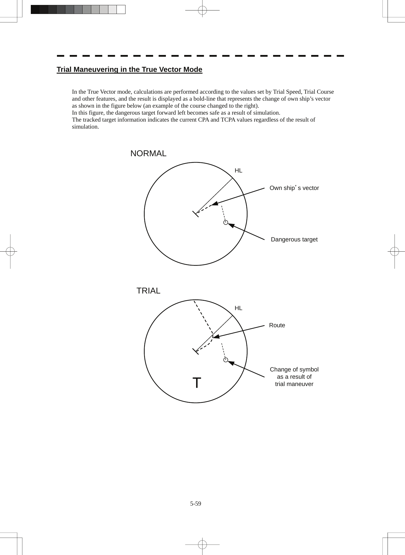
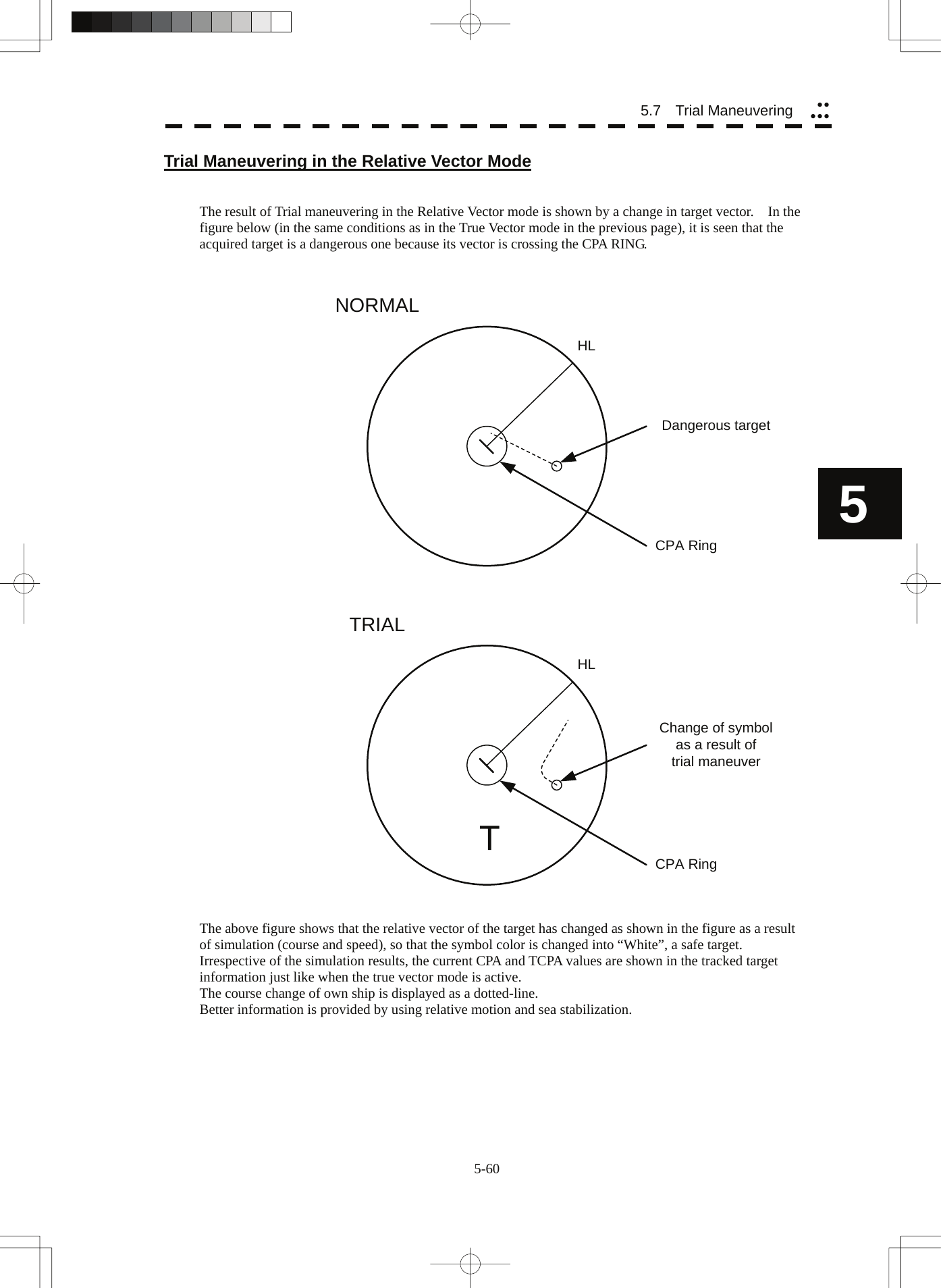
![5-61 Operation of Trial Maneuvering Function Procedures 1 Press the [TT MENU] key. 2 Open the Trial Maneuver menu by performing the following menu operation. 3. Trial Maneuver 3 Press the [1] key. The Trial Function will be set to on or off. On : The trial maneuvering function is turned on. Off : The trial maneuvering function is turned off. When the Trial Function is active, the character " T " will display at the bottom of the radar display. 4 Set values for Course by turning the [EBL] dial, and for Speed by turning the [VRM] dial. 5 Set other characteristics. Vector Time : Vector time (1 to 60 min) Time to Maneuver : Time until trial maneuvering is started (0 to 30 min) Own Ship Dynamic Trait> : Dynamic trait of the own ship → Reach : Range from when steered to when the ship beings to turn (0 to 2000 m) → Turn Radius : Turning radius (0.10 to 2.00 NM) → Acceleration : Acceleration (0.0 to 100 kn/min) → Deceleration : Deceleration (0.0 to 100 kn/min) For inputs to the value input screen, refer to Section 3.3.4. Dangerous target symbols are displayed in red and safe target symbols in white. * Vector Time is valid only when Trial Function is set to on. If it is off, the vector time before trial maneuvering is displayed. Time until the start of trial maneuvering is counted down immediately after the input. The acceleration and deceleration are influenced depending on the relationship between the current speed and the input speed for trial maneuvering. If 0.0 kn/min is set for Acceleration when the speed for trial maneuvering is faster than the current speed, or for Deceleration when the speed for trial maneuvering is slower than the current speed, the system performs simulation on the assumption that the speed is changed immediately after the time set for Time to Maneuver . Cancellation 1 Press the [1] key while the Trial Maneuver menu is displayed. The Trial Function will be set to on or off. Off : The trial maneuvering function is turned off.](https://usermanual.wiki/Japan-Radio/NKE3710.User-Manual-3/User-Guide-2120533-Page-84.png)
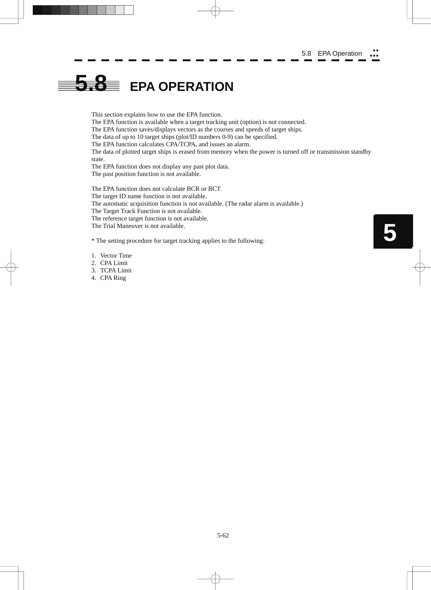
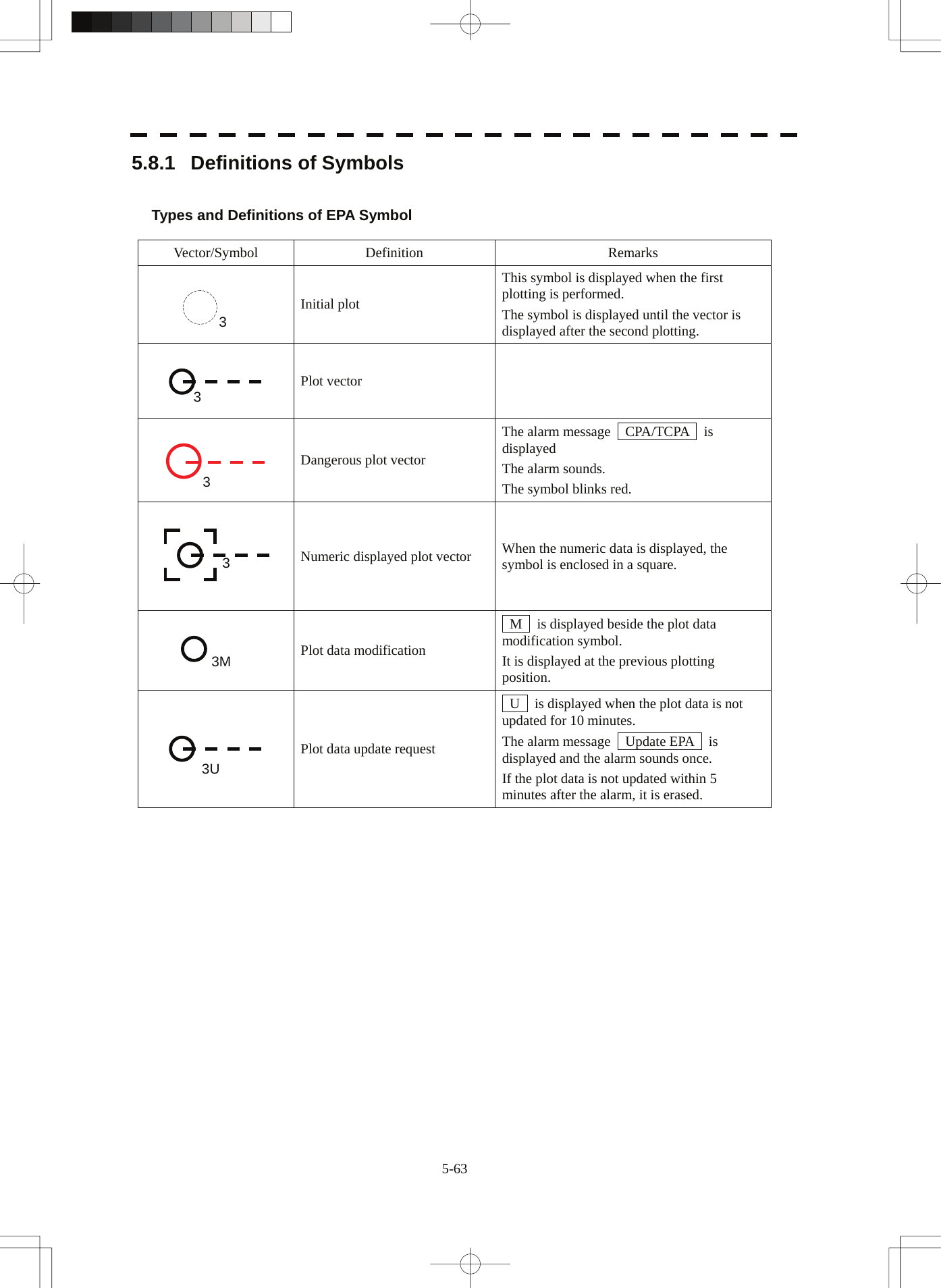
![5-64 5 55.8 EPA Operation yyyyy5.8.2 Plotting Targets Vectors are displayed when a target is plotted twice. A course and speed are calculated from the two plotting positions, and the plotted target moves in the course at the speed. The plot can be modified. The target ID number is not displayed while Display ID Number is set to off. Procedures 1 Put the cursor on the target, and press the [ACQ] key to start the first plotting. 2 Enter the plot number (target ID number), pressing [0] to [9]. 3. Press [ENT] to finish the first plotting. The symbol and plot number will be displayed at the plotting position. 4 When 30 seconds to 15 minutes has passed after the first plot, Put the cursor on the current target position, and take steps 1 to 3 to perform the second plotting. When finishing the second plotting, the system clears the symbol and plot number that were displayed at the end of the first plotting, and displays the symbol (vector) and plot number at the second plotting position. The plotted target (symbol and plot ID number) moves in a specified course at a specified speed. The course and speed are calculated from the two plotting positions. At this time, the CPA and TCPA at positions where the plotted target moves are calculated, and an alarm is issued when the plotted target goes into the dangerous judgment. 5.8.3 Modifying Plotted Target Data The system modifies specified plotted target data. It clears the specified data, and displays the plotted target immediately before it moves to the clear position until re-acquiring a target. Procedures 1 Press the [ACQ] key. 2 Enter the plot number (target ID number) for modification, pressing [0] to [9]. 3 Press the [CLR / INFO] key. The previously updated status will be displayed. M is also displayed beside the mark, indicating that modification is in progress. 4 Put the cursor on the modification position to re-acquire a target, and plotting. At this time, specify the plot number you entered in step 2. ([ACQ], [0]-[9], [ENT])](https://usermanual.wiki/Japan-Radio/NKE3710.User-Manual-3/User-Guide-2120533-Page-87.png)
![5-65 5.8.4 Canceling Plotted Target Data The system cancels the display of specified plotted target data. Once plotted target data is canceled, it cannot be re-saved any more. Procedures 1 Press the [ACQ] key. 2 Enter the plot number for cancellation, pressing [0] to [9]. 3 Press the [TGT CNCL] key. The plotted target data of the specified plot number will be canceled. Canceling all plotted targets Procedures 1 Press the [TGT CNCL] key for 5 seconds or more. The plotted targets of all the plot numbers will be canceled. 5.8.5 Displaying Numeric Data of Plotted Targets The following data is displayed for a specified plotted target: TGT ID Plot number BRG Bearing :0.1° unit Range Range :0.01 nm unit Course Target’s true course :0.1° unit Speed Target’s true speed :0.1 kn unit CPA CPA :0.01 nm unit TCPA TCPA :0.1 min unit TIME Elapsed time :0.1 min unit Procedures 1 Press the [TGT DATA] key. 2 Enter the plot number pressing [0] to [9]. 3 Press the [ENT] key. The data of the specified plot number will be displayed. The mark of the target for which numeric data is displayed is changed into “ ”.](https://usermanual.wiki/Japan-Radio/NKE3710.User-Manual-3/User-Guide-2120533-Page-88.png)
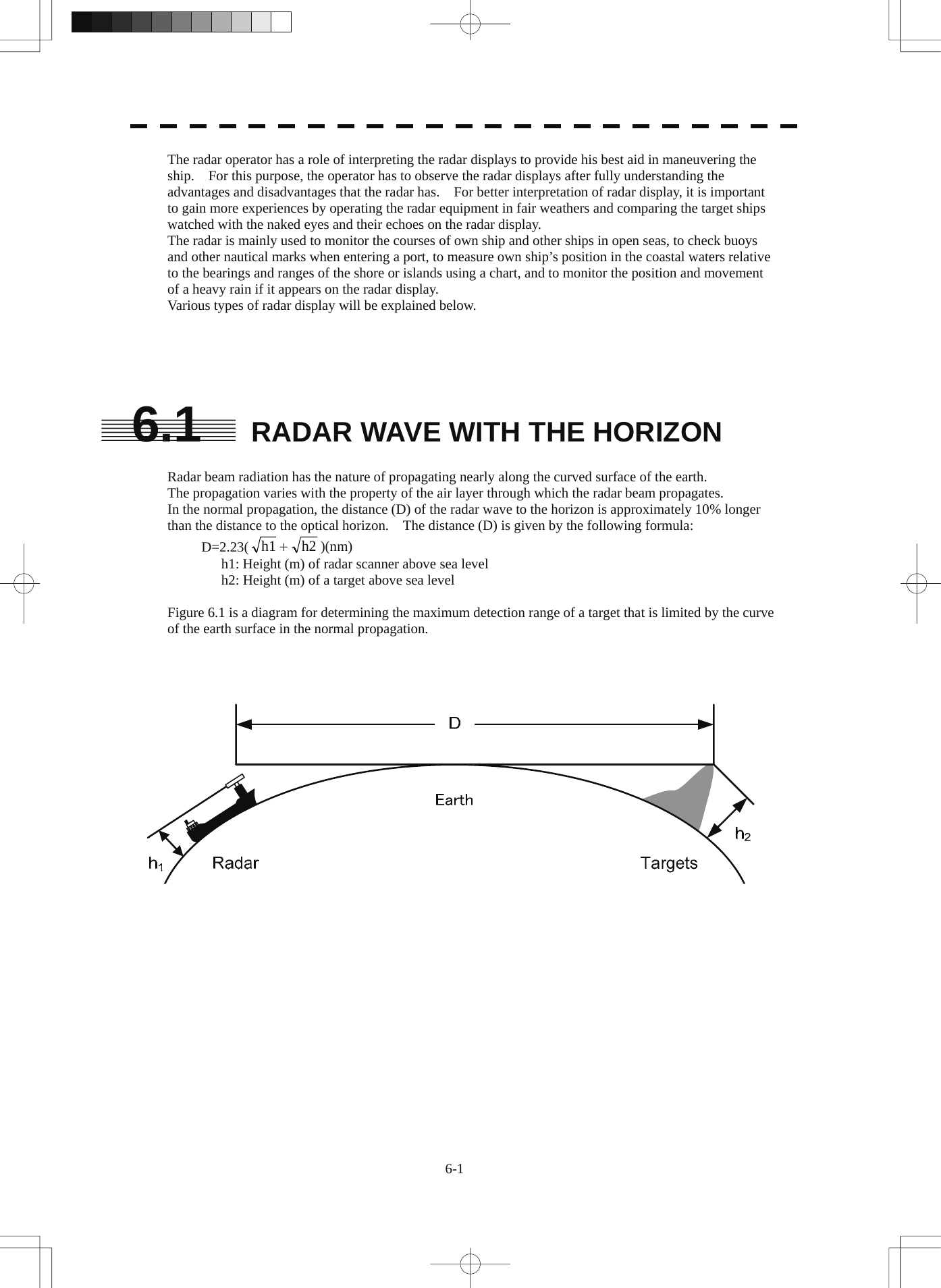
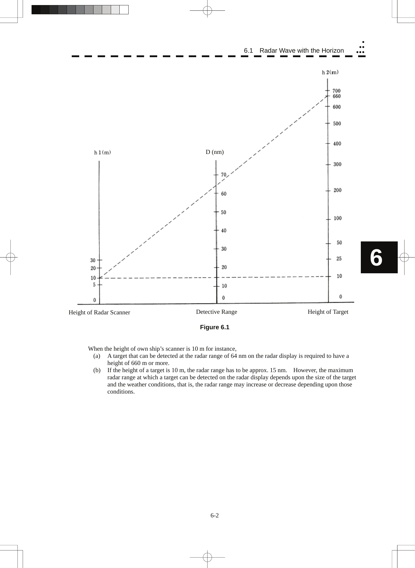
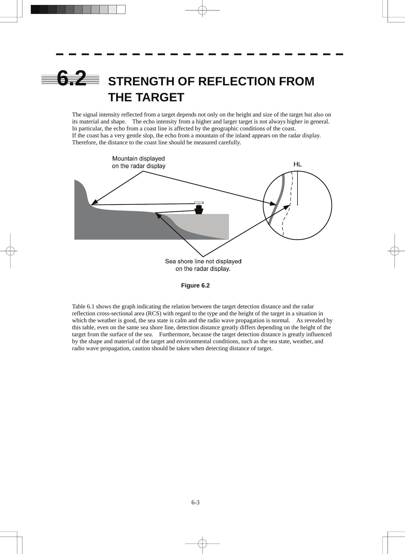
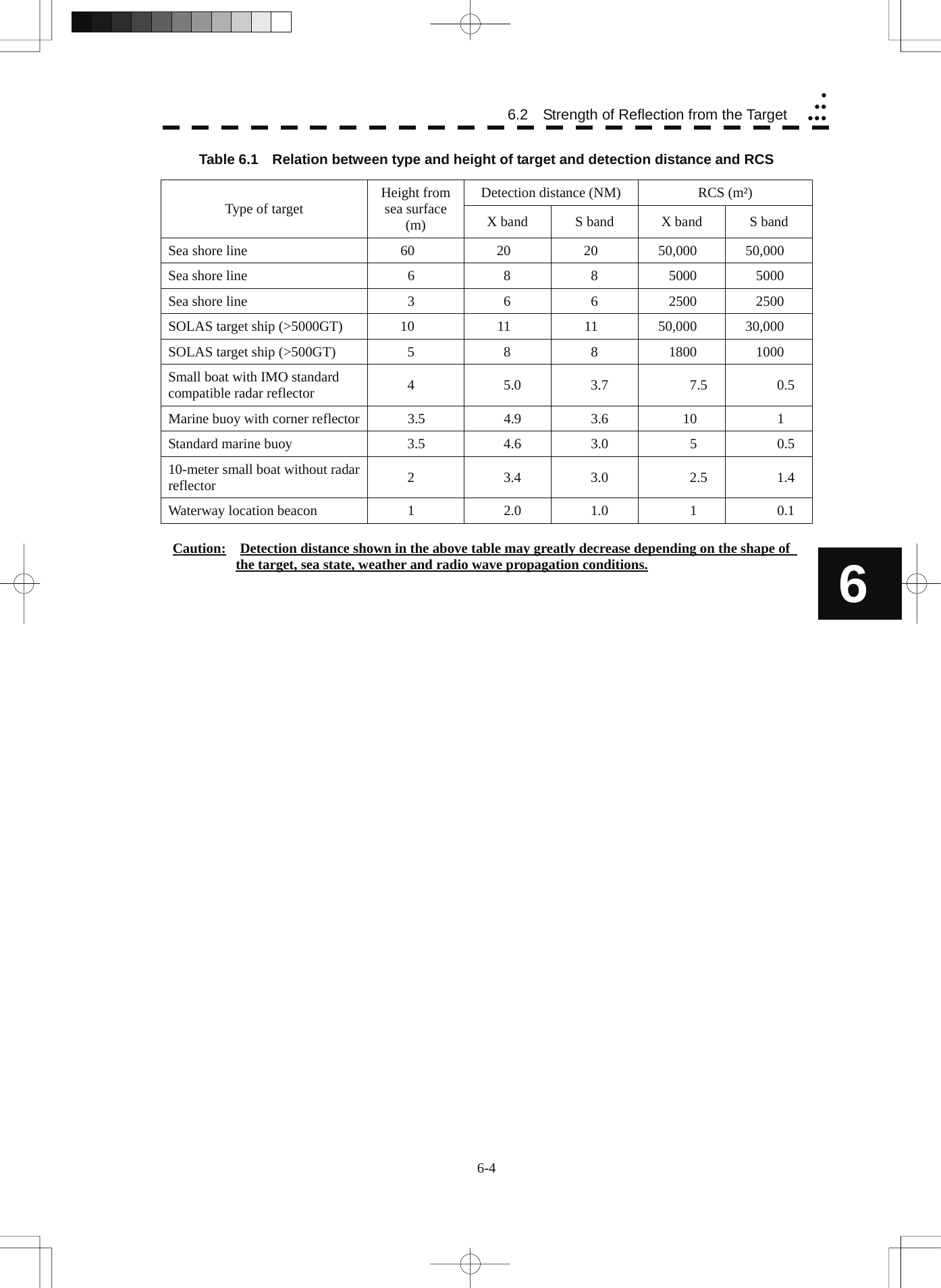
![6-5 6.3 SEA CLUTTER AND RAIN AND SNOW CLUTTER In addition to the echo required for observing ships and land radar video image also includes unnecessary echo, such as reflection from waves on the sea surface and reflection from rain and snow. Reflection from the sea surface is called "sea clutter," and reflection from rain and snow is called "rain and snow clutter," and those spurious waves must be eliminated by the clutter rejection function. [I] Sea clutter Sea clutter appears as an image radiating outwardly from the center of the radar display and changing depending on the size and the shape of waves. Generally, as waves become larger, image level of the sea clutter is intensified and the clutter far away is also displayed. When waves are large and the sea clutter level is high, it is difficult to distinguish sea clutter from a small boat whose reflection intensity is weak. Accordingly, it is necessary to properly adjust the sea clutter rejection function. Table 6.2 shows the relation between the sea state (SS) showing the size of waves generated by wind and the radar's detection probability. Table 6.2 Sea state and probability of target detection S band radar (probability to detect a target at a distance of 0.4 NM) X band radar (probability to detect a target at a distance of 0.7 NM) V: Detection probability of 80 % M: Detection probability of 50 % NV: Detection probability of less than 50 % RCS SS1 to 2 SS2 to 3 SS3 to 4 SS4 to 5 0.1m2 V V-M M-NV 0.5 m2 V V V-M M-NV 1 m2 V V V V-M RCS SS1 to 2 SS2 to 3 SS3 to 4 SS4 to 5 1m2 V-M M-NV 5 m2 V V-M M-NV 10 m2 V V V V-M](https://usermanual.wiki/Japan-Radio/NKE3710.User-Manual-3/User-Guide-2120533-Page-94.png)
![6-6 yyyyyy6 As shown in Table 6.3, the number of SS increases as the wind speed becomes high and the waves become large. Table 6.2 reveals that detection probability decreases from V (80 %) to NV (less than 50 %) as the number of SS increases. Therefore, even if the sea state is calm and a target clearly appears on the radar display, when the sea state becomes rough, target detection probability decreases resulting in difficulty of target detection by the radar. Table 6.3 Relation between Douglas sea state and average wind speed and significant wave height Significant wave height: an average of top N/3 higher waves when the number of waves detected within a constant time duration is N For example, in the case of a standard marine buoy, RCS of X band radar is 5 m2 as shown in Table 6.1. When observing such a target in the sea state (SS3) in which significant wave height exceeds 1.2 meters, detection probability is M-NV, as shown in Table 6.2, which indicates 50 % or less. [II] Rain and snow clutter Rain and snow clutter is a video image that appears in a location where rain or snow is falling. The image changes according to the amount of rain (or the amount of snowfall). As precipitation increases, the image of rain and snow clutter becomes intensified on the radar display, and in the case of localized heavy rain, an image similar to the image indicating land is displayed in some cases. Furthermore, because radio waves tend to attenuate due to rain and snow, the ability to detect a target in the rain and snow clutter or a target beyond the rain and snow clutter may decrease. The amount of attenuation depends on the transmission frequency, antenna beam width, and the pulse length. Figure 6.3 and Figure 6.4 show examples in which detection distance is reduced due to the influence of precipitation. Because of this, a target, which clearly appeared up to 10 NM by an X band radar (pulse width of 0.8 μs) when it was not raining, may become dimly visible up to 5 NM when the amount of rain becomes 4 millimeters per hour. Furthermore, when comparing the X band radar with the S band radar, target detection distance decreases less when an S band radar is used, which means it is influenced less by precipitation. Sea state Average wind speed (kn) Significant wave height (m) 0 <4 <0.2 1 5-7 0.6 2 7-11 0.9 3 12-16 1.2 4 17-19 2.0 5 20-25 3.0 6 26-33 4.0 6.3 Sea Clutter and Rain and Snow Clutter](https://usermanual.wiki/Japan-Radio/NKE3710.User-Manual-3/User-Guide-2120533-Page-95.png)
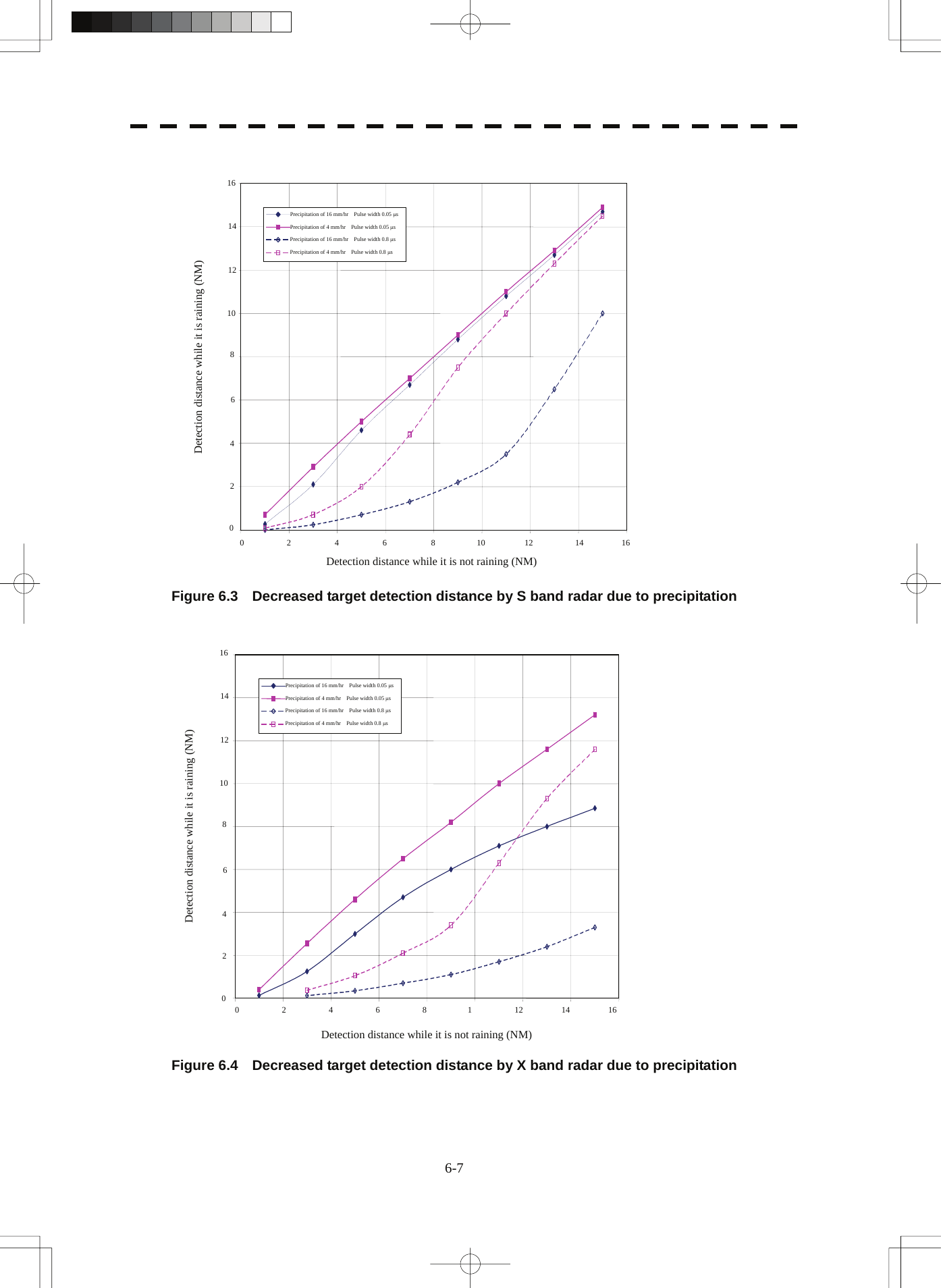
![6-8 yyyyyy6 [III] Coping with sea clutter and rain and snow clutter When the weather is bad and the ocean is rough, the use of an S band radar is effective because the radar is not influenced by sea clutter so much and attenuation due to rain drops is small. When an X band radar is used, reducing the pulse width will reduce the influence by spurious waves, and also the spurious wave rejection function effectively works; therefore, the use of short pulse is effective when the weather is bad. By using image processing functions PROC 1 to 3, it is expected that spurious waves are further suppressed. Since optimal settings for those items can be automatically made by using the function mode, it is recommended that FUNC Storm or FUNC Rain be used by selecting the function mode when the weather is bad. For details of the function mode, see Chapter 3.9. However, these functions may make some targets invisible, particularly targets with higher speeds. 6.3 Sea Clutter and Rain and Snow Clutter](https://usermanual.wiki/Japan-Radio/NKE3710.User-Manual-3/User-Guide-2120533-Page-97.png)
![6-9 6.4 FALSE ECHOES The radar observer may be embarrassed with some echoes that do not exist actually. These false echoes appear by the following causes that are well known: [I] Shadow When the radar scanner is installed near a funnel or mast, the echo of a target that exists in the direction of the funnel or mast cannot appear on the radar display because the radar beam is reflected on the funnel or mast. Whether there are some false echoes due to shadows can be checked monitoring the sea clutter returns, in which there may be a part of weak or no returns. Such shadows appear always in the same directions, which the operator should have in mind in radar operation. [II] Side Lobe Effect A broken-line circular arc may appear at the same range as the main lobe of the radar beam on the radar display. This type of false echo can easily be discriminated when a target echo appears isolated. (See Figure 6.5) HL Figure 6.5 [III] False Echo by Secondary Reflection When a target exists near own ship, two echoes from the single target may appear on the radar display. One of those echoes is the direct echo return from the target and the other is the secondary reflection return from a mast or funnel that stands in the same direction as shown in Figure 6.6. Radar scannerFunnelHLDirect microwaveSecondary reflectionof microwaveActual targetFalse echo from funnel Figure 6.6](https://usermanual.wiki/Japan-Radio/NKE3710.User-Manual-3/User-Guide-2120533-Page-98.png)
![6-10 6.4 False Echoesyyyyyy6 [IV] False Echo by Multiple Reflection When there is a large structure or ship with a high vertical surface near own ship as shown in Figure 6.7, multiple refection returns may appear on the radar display. These echoes appear in the same intervals, of which the nearest echo is the true echo of the target. Figure 6.7 [V] Second Time Echoes The maximum radar detection range depends upon the height of the scanner and the height of a target as described in the section of “The Horizon for Radar Beam Radiation”. If a so-called “duct” occurs on the sea surface due to a certain weather condition, however, the radar beam may propagate to a abnormally long distance, at which a target may be detected by the radar. For instance, assuming that the pulse length is MP3 (on the repetition frequency of 1400 Hz), the first pulse is reflected from a target at about 58 NM or more and received during the next pulse repetition time. In this case, a false echo (second time echo) appears at a position that is about 58 NM shorter than the actual distance. If the false echo appears at 5 NM on the radar display, the true distance of the target is 5+58=63 NM. On the pulse length is SP1 (on the repetition frequency of 2250 Hz), a false echo may appear at a position that is about 36 NM shorter than the actual distance. This type of false echo can be discriminated by changing over the range scale (the repetition frequency), because the distance of the target changes accordingly. If second time echo is appeared, the use of Economy mode in PRF menu is effective. Otherwise, Stagger Trigger menu set to on. (See section 3.8.3)](https://usermanual.wiki/Japan-Radio/NKE3710.User-Manual-3/User-Guide-2120533-Page-99.png)
![6-11 [VI] Radar Interference When another radar equipment using the same frequency band as that on own ship is near own ship, a radar interference pattern may appear on the radar display. This interference pattern consists of a number of spots which appear in various forms. In many cases, these spots do not always appear at the same places, so that they can be discriminated from the target echoes. (See Figure 6.8) HL HL Figure 6.8 If radar equipment causing an interference pattern and this radar are of the same model, their transmitting repetition frequency is nearly the same. As a result, interference patterns may be displayed concentrically. In this case, the interference patterns cannot be eliminated by using only the interference reflector function, so press [TX/PRF] key several times to fine-tune the transmitting repetition frequency. An interference suppressing effect can be heightened by applying a different transmitting repetition frequency to the interference pattern source radar and this radar.](https://usermanual.wiki/Japan-Radio/NKE3710.User-Manual-3/User-Guide-2120533-Page-100.png)
![6-12 yyyyyy6 6.5 DISPLAY OF RADAR TRANSPONDER (SART) The SART (Search and rescue Radar Transponder) is a survival device authorized by the GMDSS (Global Maritime Distress and Safety System), which is used for locating survivors in case that a distress accident occurs at sea. The SART is designed to operate in the 9 GHz frequency band. When receiving the 9 GHz radar signal (interrogating signal) transmitted from the radar equipment on a rescue ship or search aircraft, the SART transmit a series of response signals to inform the distress position to the rescue and search party. * This radar provides a shortcut item to make settings for SART signal reception. Execution of this item automatically switches to the setting for SART reception. It also functions for detect the beacon or target enhancer. Procedures 1 Press [RANGE +] or [RANGE -] key to set the radar range to 6 NM or 12 NM. 2 Press [RADAR MENU] key twice, and then set the SART display mode according to the procedures below. 2. RADAR Menu → 1. Process Setting → 9. SART On : SART On Off : SART Off With the SART display mode set to ON, settings as shown below are made automatically. (1) Sea clutter control: Minimum (Most counterclockwise) (2) AUTO SEA function: Off (3) Rain and Snow Clutter Control (RAIN): minimum (4) Auto Rain and Snow Clutter function (AUTO RAIN): Off (5) TUNE control: No tuning (to weaken clutter echoes) (6) Interference rejecter (IR): Off (7) PROCESS: Off 6.5 Display of Radar Transponder](https://usermanual.wiki/Japan-Radio/NKE3710.User-Manual-3/User-Guide-2120533-Page-101.png)
![6-13 z When the SART function is set to ON, small targets around own ship will disappear from the radar display. So it is necessary to exercise full surveillance over the conditions around own ship by visual watch in order to avoid any collision or stranding. z If two or more sets of radar equipment are installed on own ship, use one set of 9 GHz band radar for detection of the SART signal and operate others as normal radars for avoiding collision, monitoring targets around own ship, and checking on own ship’s position and avoidance of stranding. z After end of detecting the START signal, turn the START display off. Then the radar returns normally to the nautical mode. [Example of Display] Attention](https://usermanual.wiki/Japan-Radio/NKE3710.User-Manual-3/User-Guide-2120533-Page-102.png)
![7-1 7.1 SETTINGS AT INSTALLATION This section describes the electrical adjustment procedures to be performed by service engineers during system installation. The bearing adjustment value is saved to non-volatile memory in the scanner. Other settings are saviedto non-volatile memory in the radar process unit. CAUTION Any adjustments must be made by specialized service personnel. Incorrect settings may result in unstable operation. Do not make any adjustments during navigation. Failure to comply may result in adverse effects on the radar function which may lead to accidents or equipment failure. 7.1.1 How to Open the Serviceman Menu Procedures 1. Press the [RADAR Menu] key for 2 seconds. The Code Input menu will appear. 2. Press [0] key. 3. Put the cursor on the ENT button, and press the [ENT] key. The Serviceman Menu will appear.](https://usermanual.wiki/Japan-Radio/NKE3710.User-Manual-3/User-Guide-2120533-Page-104.png)
![7-2 7.1 Settings at Installation yyyyyyy7 7.1.2 GYRO I/F Setting The GYRO I/F circuit of the system is designed to be compatible with most types of gyro compasses by simply setting the switches. Step motor type: 20 to 170 VDC Synchro-motor type: Primary excitation voltage 35 to 120 VAC Before power-on operation can be performed, the switches S1 to S5 on the GYRO I/F circuit (PC4201) must be set in accordance with the type of your gyro compass by performing the procedure below. The switches are factory-set for a gyration ratio of 180X and the step motor type. Make sure of the type of the gyro compass installed on the own ship before starting the procedure below. Procedures 1. Set S1 to "OFF." The gyro compass and GYRO I/F are turned off. 2. Set S2 and S3 in accordance with the type of your gyro compass. There are two types of gyro compasses: one type outputs a step signal, and the other type outputs a synchro signal. Make sure of the type of the gyro compass installed on the own ship before setting the switches S2 and S3. Synchro signal: Set the switches to [SYNC]. Step signal: Set the switches to [STEP]. 3. Set the DIP switch S4. The items to be set are listed below. For the settings, refer to Table 7-1. S4-1: LOG alarm ON/OFF S4-2: GYRO simulator ON/OFF S4-3: LOG simulator ON/OFF S4-5: Time before occurrence of GYRO alarm S4-6: Sensor to be used (GYRO/NMEA) S4-7/8: Baud rate when NMEA is used 4. Set the DIP switch S5. The items to be set are listed below. For the setting, refer to Table 7-2. S5-1: Type of gyro signal (step/synchro) S5-2/3: Gyration ratio of gyro compass S5-4: Gyration direction of gyro compass S5-5: Type of log signal (pulse/synchro) S5-7/8: Ratio of log signal 5. Connect the gyro signal and log signal cables to the terminal block. 6. Set S1 to "ON." The gyro compass and GYRO I/F are connected. 7. After power-on operation, set the true bearing according to Section 7.1.7. 8. Make sure of the radar video and the operation with the true bearing value. 9. If the true bearing value of the radar equipment is reversed, change the setting of the switch S5-4.](https://usermanual.wiki/Japan-Radio/NKE3710.User-Manual-3/User-Guide-2120533-Page-105.png)
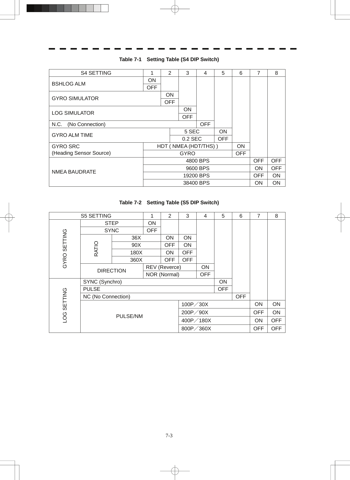
![7-4 7.1 Settings at Installation yyyyyyy7 7.1.3 Tuning [I] Tune Adjustment Adjust the tuning control for the transmitter and receiver. The turning control should be adjusted when the system is installed or when the magnetron is replaced. Procedures 1. Set the 48NM range or more.. 2. Open the Serviceman Menu. 3. Open the Tune Adjustment menu by performing the following menu operation. 1. Adjust Menu → 1. Tune Adjustment The tune mode switching (lower left of the display ⑫ on page 2-18) is changed to MAN . The tune dial position (lower left of the display on page 2-3) is changed to mediun value. 4. Adjust the tune adjustment value so that the tune indicator bar at the upper left of the display is maximized. For how to input numeric data on the numeric value input screen, see Section 3.3.4. 5. Move the cursor onto the ENT button, and press the [ENT] key. [II] Tune Indicator Adjustment Set the scale mark at the time of which tuning reached the maximum point. Procedures 1. Set the 48NM range or more.. 2. Open the Serviceman Menu. 3. Open the Tune Indicator Adjust menu by performing the following menu operation. 1. Adjust Menu → 4. TXRX Adjustment → 3. Tune Indicator Adjust 4. Adjust the tune indicator adjustment value so that the tune indicator bar at the upper left of the display reaches a point of 80 to 90% of the maximum. For how to input numeric data on the numeric value input screen, see Section 3.3.4. 5. Move the cursor onto the ENT button, and press the [ENT] key.](https://usermanual.wiki/Japan-Radio/NKE3710.User-Manual-3/User-Guide-2120533-Page-107.png)
![7-5 7.1.4 Bearing Adjustment Make adjustment so that the bearing of the target measured with the ship’s compass matches the bearing of the target echo on the radar display. Procedures 1. Select H Up for the bearing presentation. Set video processing (PROC) to OFF. 2. Measure the bearing of an adequate target (e.g., a ship at anchor, a breakwater, or a buoy) relative to own ship’s heading. 3. Open the Serviceman Menu. 4. Open the Bearing Adjustment menu by performing the following menu operation. 1. Adjust Menu → 2. Bearing Adjustment 5. Adjust the bearing adjustment value so that the target measured in step 2 is adjusted to the correct bearing. For how to input numeric data on the numeric value input screen, see Section 3.3.4. Make adjustment by the 0.1°. 6. Move the cursor onto the ENT button, and press the [ENT] key. 7.1.5 Range Adjustment Make adjustment so that the range of a target on the radar display is shown correctly. Procedures 1. Search the radar display for a target of which range is already known. 2. Open the Serviceman Menu. 3. Open the Range Adjustment menu by performing the following menu operation. 1. Adjust Menu → 3. Range Adjustment 4. Adjust the range adjustment value so that the target measured in step 1 is adjusted to the correct range. (For inputs to the value input screen, refer to Section 3.3.4.) 5. Move the cursor onto the ENT button, and press the [ENT] key.](https://usermanual.wiki/Japan-Radio/NKE3710.User-Manual-3/User-Guide-2120533-Page-108.png)
![7-6 7.1 Settings at Installation yyyyyyy7 7.1.6 Navigator Setting (Device) Determine whether to connect navigators to the radar equipment. Only the navigators set to ON here can be used. Procedures 1. Open the Serviceman Menu. 2. Open the Device Installation menu by performing the following menu operation. 2. Installation Menu → 9. Next → 3. Device Installation 3. Select On for navigators connected to the radar equipment, and Off for navigators not connected. GYRO : Gyro (via GYRO I/F) Compass : Compass (Compliant with IEC61162) GPS Compass : GPS compass produced by JRC Log : Log (via GYRO I/F) 2AXW : 2-axis log (Speed over water: Compliant with IEC61162) 2AXG : 2-axis log (Speed over ground: Compliant with IEC61162) GPS : GPS (Compliant with IEC61162) 7.1.7 Setting of True Bearing Value If GYRO I/F is used to input a gyro signal, the true bearing value indicated by the master gyro does not match the value indicated by the radar equipment only in a rare case. In this case, perform the following procedure to adjust the true bearing value of the radar equipment to the value of the master gyro. Procedures 1. Press the [RADAR MENU] key twice. 2. Open the GYRO Setting menu by performing the following menu operation. 4. NAV Equipment Setting → 1. GYRO Setting 3. Input the master gyro value to the value input screen. (For inputs to the value input screen, refer to Section 3.3.4.) 4. Move the cursor onto the ENT button, and press the [ENT] key.](https://usermanual.wiki/Japan-Radio/NKE3710.User-Manual-3/User-Guide-2120533-Page-109.png)
![7-8 7.1 Settings at Installation yyyyyyy7 7.1.9 Setting of CCRP/Antenna/GPS Antenna Position (CCRP Setting) Set the own ship's CCRP location, radar antenna installation location, and GPS installation location. CCRP : Up to four locations can be input. (One location selected when used) Radar antenna : Up to eight radar antennas can be input. (Automatically selected in response to ISW operation) GPS : Up to four locations can be input. (One location selected when used) Procedures 1. Measure the CCRP location, radar antenna location, and GPS antenna location in advance. 2. Open the Serviceman Menu. 3. Open the CCRP Setting menu by performing the following menu operation. 2. Installation Menu → 4. CCRP Setting 4. Specify the ship length for Length at the upper right of the CCRP Setting Menu, and the ship width for Beam. 5. Move the cursor onto the CCRP1 X, Y value, and press the ENT key to input the CCRP1 location. When X > 0, the CCRP is on the starboard side of the ship. When X < 0, it is on the port side. 6. To input the second CCRP, press the CCRP2 button to display the CCRP2 X,Y value, and input the value in the same manner for step 5. Similarly, input the third and subsequent CCRPs. 7. Repeat the above steps to input the GPS location(s) and radar antenna location(s). 8. If multiple CCRP locations and GPS locations are input, select the CCRP location and GPS location to be used by pressing the buttons at the upper left of the menu. 9. Press [0] key to close the CCRP Setting menu.](https://usermanual.wiki/Japan-Radio/NKE3710.User-Manual-3/User-Guide-2120533-Page-111.png)
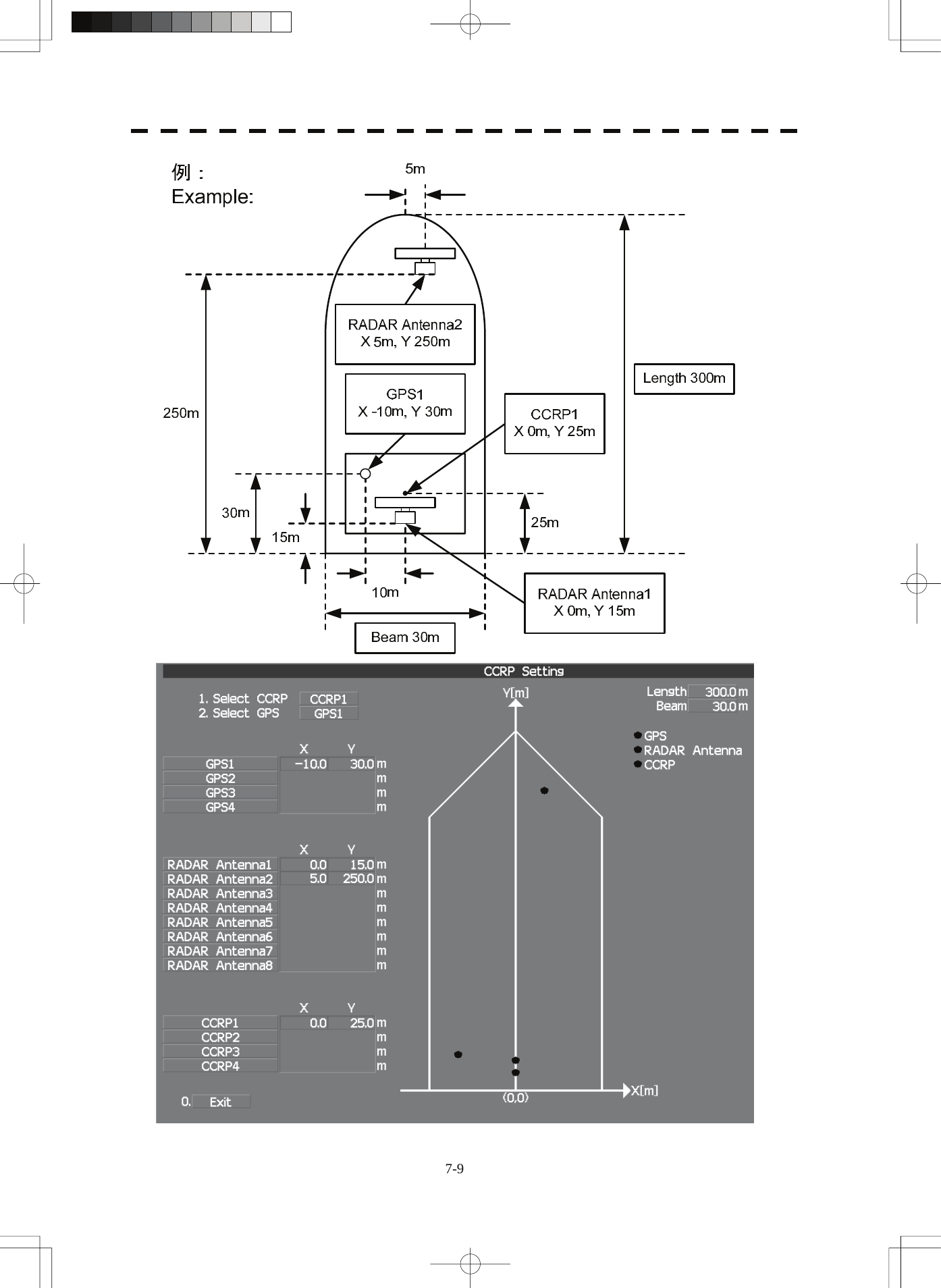
![7-10 7.2 Settings yyyyyyy7 7.2 SETTINGS This section describes the electrical adjustment procedures to be performed by service engineers during system installation. CAUTION Any adjustments must be made by specialized service personnel. Incorrect settings may result in unstable operation. Do not make any adjustments during navigation. Failure to comply may result in adverse effects on the radar function which may lead to accidents or equipment failure. 7.2.1 Communication Port Setting (COM Port Setting) External sensor signals are input to the radar equipment through a communication port. The radar equipment has five communication ports. For signals to be input from sensors or to be output to the sensors, communication ports need to be set in accordance with the sensors. [I] Baud Rate Setting Set the baud rate of the signal to be input to the COM port. Procedures 1. Open the Serviceman Menu. 2. Open the Baud Rate menu by performing the following menu operation. 2. Installation Menu → 5. COM Port Setting → 1. Baud Rate](https://usermanual.wiki/Japan-Radio/NKE3710.User-Manual-3/User-Guide-2120533-Page-113.png)
![7-11 3. Set the baud rate of the port to be set. Selection value 1. COMPASS : 4800(NMEA)/9600(NSK)/38400(Fast NMEA) bps 2. NAV1 : 1200/4800/9600/38400 bps 3. NAV2 : 1200/4800/9600/38400 bps 4. GPS : 1200/4800/9600/38400 bps 5. NMEA : 1200/4800/9600/38400/115200 bps The bold values are factory-set. The COMPASS port is a receive-only port that is dedicated to COMPASS signals. [II] Reception Port Setting (RX Port) Set the numbers of ports for receiving signals from sensors. There are two methods for receiving signals: specifying a port for each sensor, or using the automatic recognition function without specifying ports. Procedures 1. Open the Serviceman Menu. 2. Open the RX Port menu by performing the following menu operation. 2. Installation Menu → 5. COM Port Setting → 2. RX Port 3. Set a port for each sensor. Settable sensor signals GPS, DLOG, Alarm, Depth, Temperature, Wind, Current, ROT, RSA Selectable ports When the automatic recognition function is used: AUTO When ports are specified: NAV1, NAV2, GPS, and NMEA](https://usermanual.wiki/Japan-Radio/NKE3710.User-Manual-3/User-Guide-2120533-Page-114.png)
![7-12 7.2 Settings yyyyyyy7 [III] Reception Sentence Setting (RX Sentence) Set signal sentences to be received from sensors. The system is factory-set for using all sentences. To receive only specified sentences, select No Use for sentences which are not necessary. Procedures 1. Open the Serviceman Menu. 2. Open the RX Sentence menu by performing the following menu operation. 2. Installation Menu → 5. COM Port Setting → 3. RX Sentence 3. Select the sentences to be used by the sensors to be set. Selection value: Use or Not Use can be selected for each sentence. 1. GPS(LL/COG/SOG) > : GGA/RMC/RMA/GNS/GLL/VTG 2. GPS(WPT/Time) > : GGA/RMC/RMB/BWC/BWR/ZDA 3. Depth > : DPT/DBK/DBT/DBS 4. Wind > : MWV/MWD 5. Current > : Data Set Number : 0-9. Set the number of the sentence to be used by Data Set Number. (Initial value All) Layer A : 0-999. Set the number of the sentence to be used with layer A by Layer Number. (default value : 3) Layer B : 0-999. Set the number of the sentence to be used with layer B by Layer Number. (default value : 4) Layer C : 0-999. Set the number of the sentence to be used with layer C by Layer Number. (default value : 5) 6. Autopilot > : APB (default value : Not Use)](https://usermanual.wiki/Japan-Radio/NKE3710.User-Manual-3/User-Guide-2120533-Page-115.png)
![7-13 [IV] Transmission Port Setting (TX Port) For each sentence, set a communication port through which signals are transmitted to sensors. Procedures 1. Open the Serviceman Menu. 2. Open the TX Port menu by performing the following menu operation. 2. Installation Menu → 5. COM Port Setting → 4. TX Port 3. Select the communication port through which the sentence to be set is output. Settable sentences TTM(TT), TLL(TT), TTD(TT), TLB(TT), OSD, RSD, ALR, ACK, TTM(AIS), TLL(AIS), TTD(AIS), TLB(AIS), RemoteMaintenance, JRC-ARPA, APB, BOD, GGA, GLL, RMC, RMB, VTG, XTE, BWC, HDT, THS Selectable ports NAV1, ARPA, GPS, and NMEA 4. Select the output format, talker, and transmission interval. Signals for which the above items can be set: • NMEA0183 Output Format Signal names: APB, BOD, GGA, GLL, RMC, RMB,VTG, XTE, BWC, HDT, THS Selection Value: V1.5, V2.0, and V2.3 • NMEA0183 Talker Signal names: APB, BOD,RMB, XTE, BWC, HDT, THS Selection Value: Standard: The talker is RA. GP: The talker is GP. For TTM, TLL, TTD, TLB, OSD, RSD and ALR the talker is always RA . For GGA, GLL, RMC, and VTG, the talker is always GP. • NMEA0183 TX Interval Signal names: APB, BOD, GGA, GLL, RMC, RMB,VTG, XTE, BWC, HDT, THS Selection Value: Set an interval in the range 1 to 9 seconds.](https://usermanual.wiki/Japan-Radio/NKE3710.User-Manual-3/User-Guide-2120533-Page-116.png)
![7-14 7.2 Settings yyyyyyy7 [V] GPS Receive Port Setting (Select NAV Equipment) Select the receive port of GPS data. Procedures 1. Open the Serviceman Menu. 2. Open the COM Port setting menu by performing the following menu operation. 2. Installation Menu → 5. COM Port Setting 3. Press the [5] key. Units of Select NAV Equipment are switched. Internal GPS : The receive port is selected GPS connector of processor unit (JRC’s GPS). External GPS : The receive port is selected GPS terminal of terminal board circuit. 7.2.2 Sector Blank Setting (Sector Blank) In order not to display radar echoes, set a sector and stop transmission in the bearing. Three sector blank areas can be created. The sector blank function operates in the relative bearing with the bow. [I] Sector Blank Function On/Off (Sectors 1, 2, and 3) Procedures 1. Open the Serviceman Menu. 2. Open the Sector Blank menu by performing the following menu operation. 2. Installation Menu → 3. Sector Blank 3. Set the sector blank number Sector 1 , 2 , or 3 with which the sector blank function operates. The system allows the use of up to three sector blank areas. Set each sector blank area to on or off. On : The sector blank function is operated. Off : The sector blank function is stopped.](https://usermanual.wiki/Japan-Radio/NKE3710.User-Manual-3/User-Guide-2120533-Page-117.png)
![7-15 [II] Sector Blank Area Creation (Make Sectors 1, 2, and 3) Procedures 1. Transmit the radar. 2. Open the Serviceman Menu. 3. Open the Sector Blank menu by performing the following menu operation. 2. Installation Menu → 3. Sector Blank 4. Press numeric keys corresponding to the desired sector creation Make Sector 1 , 2 , or 3 . The selected sector blank will be made. 5. Set the starting bearing of the sector blank by operating the [EBL] dial, and press the [ENT] key. 6. Set the ending azimuth of the sector blank by operating the [EBL] dial, and press the [ENT] key. 7.2.3 TNI Blank Setting (TNI Blank) Set a sector and stop tuning operation in the bearing. If a structure such as the mast is close to the radar antenna, automatic tuning operation may become unstable. In this case, set a TNI blank in the direction of the structure in order to stabilize the tuning operation. Only one TNI blank sector can be created. The TNI blank function operates in the relative bearing with the bow as the benchmark. [I] TNI Blank Function On/Off (Sector) Procedures 1. Open the Serviceman Menu. 2. Open the TNI Blank menu by performing the following menu operation. 2. Installation Menu → 9. Next → 2. TNI Blank 3. Select the item 1. TNI Blank in the menu, and turn on or off the TNI blank function. On : The TNI blank function is operated. Off : The TNI blank function is stopped.](https://usermanual.wiki/Japan-Radio/NKE3710.User-Manual-3/User-Guide-2120533-Page-118.png)
![7-16 7.2 Settings yyyyyyy7 [II] TNI Blank Area Creation (Make Sector) Procedures 1. Transmit the radar. 2. Open the Serviceman Menu. 3. Open the TNI Blank menu by performing the following menu operation. 2. Installation Menu → 9. Next → 2. TNI Blank 4. Press the 2. Make Sector button in the menu. 5. Set the starting bearing of the TNI blank by operating the [EBL] dial, and press the [ENT] key. 6. Set the ending bearing of the TNI blank by operating the [EBL] dial, and press the [ENT] key. 7.2.4 Setting of Bearing Pulses from Antenna (Output Pulse) Set the output value of bearing pulses from the antenna. The system can set 2048 pulses or 4096 pulses. Procedures 1. Open the Serviceman Menu. 2. Open the Output Pulse menu by performing the following menu operation. 1. Adjust Menu → 4. TXRX Adjustment → 6. Output Pulse 3. Set the number of pulses to be output by the antenna. 2048 : 2048 pulses per antenna rotation (Recommended value) 4096 : 4096 pulses per antenna rotation](https://usermanual.wiki/Japan-Radio/NKE3710.User-Manual-3/User-Guide-2120533-Page-119.png)
![7-17 7.2.5 Slave Mode Setting (Master/Slave) Place the system in the Slave mode when it is to be operated as the sub-display that displays radar echoes by using radar signals from other radar equipment. The input value of externally input bearing pulses can be set. The system can set 2048 pulses or 4096 pulses. [I] Slave Mode Setting (Master/Slave) Procedures 1. Open the Serviceman Menu. 2. Open the Installation Menu by performing the following menu operation. 2. Installation Menu 3. Select Slave for the item 2. Master/Slave in the menu. Master : The system operates as radar equipment while the own antenna is connected. Slave : The system operates as a sub-display while the signal cable of other radar equipment is connected. [II] Setting of Input Bearing Pulse (Input BP Count) Procedures 1. Open the Serviceman Menu. 2. Open the second page of the Installation Menu by performing the following menu operation. 2. Installation Menu → 9. Next 3. Set the number of pulses for the item 1. Input BP Count in the menu. 2048 : 2048 pulses per antenna rotation 4096 : 4096 pulses per antenna rotation](https://usermanual.wiki/Japan-Radio/NKE3710.User-Manual-3/User-Guide-2120533-Page-120.png)
![7-18 7.2 Settings yyyyyyy7 7.2.6 Language Setting (Language) The system is designed to switch between display languages, English and Japanese. Procedures 1. Open the Serviceman Menu. 2. Open the Language menu by performing the following menu operation. 2. Installation Menu → 8. Language 3. Select the language to be used. 1. English 2. Japanese 3. Other 3. Other is an option to display character strings created by our agents. Ask the agent or our sales department if your language is supported. 4. To determine the selected language, turn the radar off, and then turn it on. 7.2.7 Date Time Setting To display time, the local time, local date, and time-zone difference must be set. However, if the "ZDA" sentence of NMEA0183 is received, time can be automatically displayed. Procedures 1. Press the [RADAR MENU] key twice. 2. Open the Date/Time Setting menu by performing the following menu operation. 5. Sub Menu → 6. Date/Time Setting](https://usermanual.wiki/Japan-Radio/NKE3710.User-Manual-3/User-Guide-2120533-Page-121.png)
![7-19 2. Set information about date and time. [1] UTC/LMT (Time display system) UTC : Universal Time Coordinate LMT : Local Mean Time [2] LMT Date Input the date in local time. [3] LMT Time Input the time in local time. [4] Time Zone Input the time-zone difference between the universal time and local time. [5] Display Style Set one of the following date display formats. YYYY-MM-DD : Example: 2007-12-31 MMM DD, YYYY : Example: Dec 31, 2007 DD MMM YYYY : Example: 31 Dec 2007 [6] Synchronize with GPS A ZDA sentence sent by the GPS is used, thereby displaying time synchronized with the GPS time. On : Time synchronized with the GPS time Off : Time not synchronized with the GPS time * If On is selected for this item but a ZDA sentence is not input, the system internal clock function is used to display the date and time. 7.2.8 Input Installation Information The system can input installation information. Procedures 1. Open the Serviceman Menu. 2. Open the Installation Information menu by performing the following menu operation. 2. Installation Menu → 1. Installation Information 3. Input the installation information. For the input method on the numeric value and character input screens, see Section 3.3.4. [1] Date Input the date of installed system. [2] Name Input the name of installation personel. [3] Company Input the name of radar installer.](https://usermanual.wiki/Japan-Radio/NKE3710.User-Manual-3/User-Guide-2120533-Page-122.png)
![7-20 7.2 Settings yyyyyyy7 7.2.9 Setting the Alarm System Setting the relay output (Relay Output) This function enables the control of ARPAALM terminal (on the terminal board circuit). Procedures 1. Open the Serviceman Menu. 2. Open the Relay Output menu by performing the following menu operation. 2. Installation Menu → 6. Alarm System → 2. Relay Output 3. Press the [1] key. The Relay Output mode is switched. Continuous : The output is continuously controlled. Intermittent : The output is intermittenly controlled. 4. Press the [numeric] key corresponding to the item to be changed. The item can be turned on / off. On : The relay output is turned on when alarm have issued. Off : The relay output is not turned on when alarm have issued. 2. TT CPA/TCPA : There is a dangerous target. (tracked target) 3. AIS CPA/TCPA : There is a dangerous target. (AIS target) 4. New Target : A new target is acquired in the automatic acquisition zone. 5. Lost : There is a lost target. (Target Tracking / AIS). 6. RADAR Alarm : Targets have entered the radar alarm range. Setting the ALR output (ALR Output) This function enables the control of ALR port (See the section 7.2.1). Procedures 1. Open the Serviceman Menu. 2. Open theALR output menu by performing the following menu operation. 2. Installation Menu → 6. Alarm System → 3. ALR Output 3. Press the [numeric] key corresponding to the item to be changed. The item is turned on / off. On : The ALR sentence is output when alarm have issued. Off : The ALR sentence is not output when alarm have issued. 1. System Alarm : The internal alarm. 2. TT/AIS Alarm : Target Tracking Alarms and AIS Function Alarms.](https://usermanual.wiki/Japan-Radio/NKE3710.User-Manual-3/User-Guide-2120533-Page-123.png)
![7-21 Setting the External Acknowledgement (External ACK Setting) This function enables the control of system when ACK sentence have received. Procedures 1. Open the Serviceman Menu. 2. Open the External ACK Setting menu by performing the following menu operation. 2. Installation Menu → 6. Alarm System → 5. External ACK Setting 3. Press the [numeric] key corresponding to the menu to be changed. Critical Alarm :CPA/TCPA alarm. Normal Alarm :Exept Critical Alarm. 4. Press the [numeric] key corresponding to the item to be changed. The item is switched. Audio : Setting of alarm sound. On : The alarm sound is not stopped when acknowridgement have received. Off : The alarm sound is stopped when acknowridgement have received. Indication : Setting of alarm indication. Lighting : The alarm indication brinking is stopped when acknowridgement have received. Brinking : The alarm indication brinking is not stopped when acknowridgement have received. Acknowridge State : Setting of ALR sentence. A:ACK : Add acknowridgement to ALR sentence. V:UNACK : Add no acknowridgement (unrecognized) to ALR sentence.](https://usermanual.wiki/Japan-Radio/NKE3710.User-Manual-3/User-Guide-2120533-Page-124.png)
![7-22 7.3 Adjustment yyyyyyy7 7.3 ADJUSTMENT This section describes the electrical adjustment procedures to be performed by service engineers during system installation. CAUTION Any adjustments must be made by specialized service personnel. Incorrect settings may result in unstable operation. Do not make any adjustments during navigation. Failure to comply may result in adverse effects on the radar function which may lead to accidents or equipment failure. 7.3.1 Noise Level Adjustment (Noise Level) [I] Noise Level Adjustment for Signal Processing Procedures 1. Open the Serviceman Menu. 2. Open the Echo Noise Level menu by performing the following menu operation. 9. SP/TT Initial Setup → 1. Signal Processing → 1. Echo Noise Level 3. Increase/decrease the noise level adjustment value. The noise level is factory-set. After system installation, a great change in the noise level adjustment value should be avoided; it should be fine adjusted within ±5.](https://usermanual.wiki/Japan-Radio/NKE3710.User-Manual-3/User-Guide-2120533-Page-125.png)
![7-23 [II] Noise Level Adjustment Mode (Setting Mode) A noise level is factory-adjusted while this mode is turned on. Procedures 1. Open the Serviceman Menu. 2. Open the Signal Processing menu by performing the following menu operation. 9. SP/TT Initial Setup → 1. Signal Processing 3. Press the [2] key. The noise level setting mode is switched between on and off. Factory-adjustment method • The GAIN control is set to the maximum position, the SEA control is set to the minimum position, the RAIN control is set to the minimum position, and IR, AUTO-SEA, AUTO-RAIN, PROC, FUNC, and TRAILS are all set to off. • The noise level adjustment mode is turned on. • While the noise level adjustment value is decreased gradually, the value with which radar echoes no longer appear is determined as the set value. • Ten is added to the set value (with which radar echoes no longer appear), and the result is set as the final noise level adjustment value. • The noise level adjustment mode is turned off when the adjustment is finished.](https://usermanual.wiki/Japan-Radio/NKE3710.User-Manual-3/User-Guide-2120533-Page-126.png)
![7-24 7.3 Adjustment yyyyyyy7 z Do not change the set value carelessly. The vector constant shall be set to 4 normally. If the vector constant value is higher, a target’s vector will be better followed up when the target and own ship change their course or speed, but the vector accuracy will be lower on the contrary. 7.3.2 Adjustment of Target Tracking Function (TT) CAUTION Optimal values have been set for Video Level and Vector Constant; therefore, never change their values unless absolutely necessary. Failure to comply may result in accidents that would lower target tracking performance. [I] Vector Constant Adjustment (Vector Constant) Adjust the vector follow-up performance of the target tracking function. The vector constant is adjusted to an optimal value, so do not change it carelessly. Procedures 1. Open the Serviceman Menu. 2. Open the Vector Constant menu by performing the following menu operation. 9. SP/TT Initial Setup → 2. TT → 1. Vector Constant 3. Input the value to be set. To improve vector follow-up performance, increase the set value. To stabilize vectors, decrease the set value. Attention](https://usermanual.wiki/Japan-Radio/NKE3710.User-Manual-3/User-Guide-2120533-Page-127.png)
![7-25 [II] Quantization Level Adjustment (Video Level) Use the target tracking function (TT) to adjust the level of the signal to be recognized as a target. If a small value is set, even weak target signals will be input to the target detection circuit of the target tracking function. However, many unnecessary signals are also input, which may cause unstable target acquisition or tracking. It is important to set a value four or five greater than the value with which unnecessary signals are detected. The quantization level is adjusted to an optimal value, so do not change it carelessly. CAUTION Do not change the quantization level settings unless absolutely necessary. If set at an inappropriate value, the target acquisition or target tracking function deteriorates, and this may lead to accidents. Procedures 1. Open the Serviceman Menu. 2. Open the TT (Target Tracking) menu by performing the following menu operation. 9. SP/TT Initial Setup → 2. TT 3. To change the quantization level of the automatic acquisition area, specify the item 2. Video TD Level in the menu. To change the quantization level of tracking and manual acquisition, specify the item 3. Video High Level .](https://usermanual.wiki/Japan-Radio/NKE3710.User-Manual-3/User-Guide-2120533-Page-128.png)
![7-26 7.3 Adjustment yyyyyyy7 [III] Gate Size Adjustment (Gate Size) Use the target tracking function (TT) to set a target search area. The gate size is adjusted to an optimal value, so do not change it carelessly. Procedures 1. Open the Serviceman Menu. 2. Open the Gate Size menu by performing the following menu operation. 9. SP/TT Initial Setup → 2. TT → 5. Gate Size 3. Select a gate size. Wide : Large gate size Normal : Medium gate size Narrow : Small gate size [IV] CPA Limit Ring Display On/Off (Limit Ring) Use the target tracking function (TT) to determine whether to display the CPA limit for determining a dangerous ship. When the CPA limit ring display function is turned on and a relative vector is used, the CPA limit ring is displayed as a red circle. Procedures 1. Open the Serviceman Menu. 2. Open the TT (Target Tracking) menu by performing the following menu operation. 9. SP/TT Initial Setup → 2. TT 3. Press the [6] key. The Limit Ring item is turned on / off. Off : Limit ring not displayed On : Limit ring displayed](https://usermanual.wiki/Japan-Radio/NKE3710.User-Manual-3/User-Guide-2120533-Page-129.png)
![7-27 7.3.3 Main Bang Suppression Adjustment (MBS) Main Bang Suppression is adjusted to suppress main bang, a reflection signal from 3D circuit including wave guide tube, that generally appears as a circular video focusing on the center of the radar display. Optimum adjustment allows main bang video to remain slightly on the display. WARNING Do not change MBS Level/Area unless absolutely necessary. Incorrect adjustment will result in deletion of nearby target images and thus collisions may occur resulting in death or serious injuries. Procedures 1. Open the Serviceman Menu. 2. Open the MBS menu by performing the following menu operation. 9. SP/TT Initial Setup → 3. MBS 3. Set the radar as follows: • Set the radar video enhance function and video processing (PROC) to OFF. • Turn the [RAIN] control to the minimum position (fully to the left). • Turn the [GAIN] control to the maximum position (fully to the right). • Turn the [SEA] control to achieve the strength with which main bang can be judged. 4. Set 20 for 2. MBS Area . 5. Adjust the value set for 1. MBS Level so that the main bang remains slightly. 6. Adjust the value set for 2. MBS Area so that the suppression area will match the main bang.](https://usermanual.wiki/Japan-Radio/NKE3710.User-Manual-3/User-Guide-2120533-Page-130.png)
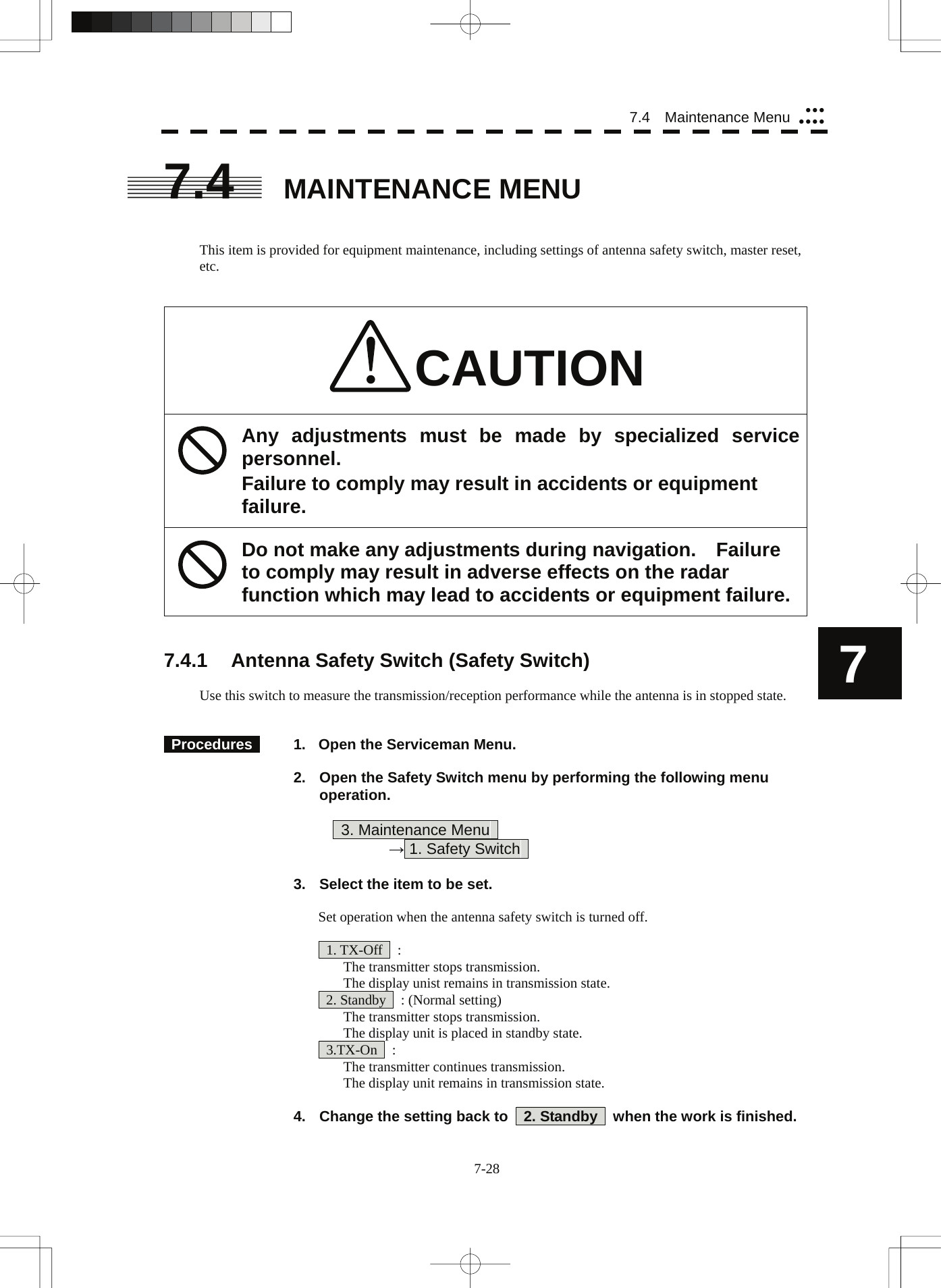
![7-29 7.4.2 Initialization of Memory Area (Area Initial) If system operation is unstable, it may be stabilized by initializing the memory area. To initialize the memory area, follow the procedure in this section. The memory area is reset to the factory setting when initialized. [I] Partial Master Reset Procedures 1. Open the Serviceman Menu. 2. Open the Partial Master Rest menu by performing the following menu operation. 3. Maintenance Menu → 2. Area Initial → 1. Partial Master Reset 3. Select the items to be initialized. Serviceman Menu : The set values in the Serviceman menu are initialized. Except Serviceman Menu : The set values not in the Serviceman menu are initialized. User Setting : The user setting values are initialized. TT Setting : The set values for the target tracking function are initialized. AIS Setting : The set values for the AIS function are initialized. Day/Night : The color scheme and brilliance setting for the day/night mode are initialized. JRC Card Copy Record : The history of JRC charts copied on the memory card is erased. 4. Select Yes in the Confirmation Window. The memory areas of specified items are initialized, and the system is restarted. [II] All Master Reset Procedures 1. Open the Serviceman Menu. 2. Open the All Master Rest menu by performing the following menu operation. 3. Maintenance Menu → 2. Area Initial → 2. All Master Reset 3. Select Yes in the Confirmation Window. The whole memory area is initialized, and the system is restarted.](https://usermanual.wiki/Japan-Radio/NKE3710.User-Manual-3/User-Guide-2120533-Page-132.png)
![7-30 7.4 Maintenance Menu yyyyyyy7 7.4.3 Save of Internal Memory Data (Card1/2) The system can save internal memory data such as item settings in all menus onto a flash memory card. If the radar processing circuit in the system has been replaced, the set values before the circuit replacement can be restored by reading the set values you saved before the replacement. To save the internal memory data onto a flash memory card (option), the card must be inserted in card slot beforehand. [I] Copying of Internal Settings onto Card (Internal to Card1/2) Save the internal memory data, such as item settings in menus, onto a flash memory card. The internal memory data should be saved at completion of system setting, and the operation condition should be saved periodically. Procedures 1. Open the Serviceman Menu. 2. Open the Internal to Card 1/2 menu by performing the following menu operation. 3. Maintenance Menu → 3. Internal to Card1/2 3. Select the slot of the card on which the internal memory data is to be saved. The lower slot is slot 1; the upper slot is slot 2. 4. Select Yes in the Confirmation Window. The internal memory data is saved on the flash memory card. [II] Reading of Internal Settings from Card (Card1/2 to Internal) Read the saved memory data from the flash memory card into the system memory. Perform the read operation in order to return the system to the previous operation condition after replacement of the radar processing circuit in the system. Procedures 1. Open the Serviceman Menu. 2. Open the Card 1/2 to Internal menu by performing the following menu operation. 3. Maintenance Menu → 4. Card1/2 to Internal 3 Select the slot of the card from which the previously saved internal memory data is to be read. The lower slot is slot 1; the upper slot is slot 2. 4. Select Yes in the Confirmation Window. The memory data is read from the flash memory card into the system memory. After the internal memory area is updated, the system is restarted.](https://usermanual.wiki/Japan-Radio/NKE3710.User-Manual-3/User-Guide-2120533-Page-133.png)
![7-31 7.4.4 Clear and Save/Restoration of Antenna Operation Time (TXRX Time) The system adds up the following operation time and contains it in the antenna unit: • Transmission time • Motor run time Clear the above total time when the magnetron or antenna unit motor is replaced. [I] Clear of Transmission Time (Clear TX Time) Clear the transmission time of the antenna unit. Perform the following procedure to clear the transmission time when the magnetron is replaced. Procedures 1. Open the Serviceman Menu. 2. Open the Clear TX Time menu by performing the following menu operation. 3. Maintenance Menu → 5. TXRX Time → 1. Clear TX Time 3. Select Yes in the Confirmation Window. The transmission time in the antenna's internal control circuit is cleared to 0. [II] Clear of Motor Run Time (Clear Motor Time) The Clear Motor Time Function is unavailable in The JMA-5352-9R and JMA-5362-8R. [III] Save of Antenna Time (TXRX to Display Unit) The TXRX to Display Unit Function is unavailable in The JMA-5352-9R and JMA-5362-8R. [IV] Restoration of Antenna Time (Display Unit to TXRX) The Display Unit to TXRX Function is unavailable in The JMA-5352-9R and JMA-5362-8R.](https://usermanual.wiki/Japan-Radio/NKE3710.User-Manual-3/User-Guide-2120533-Page-134.png)
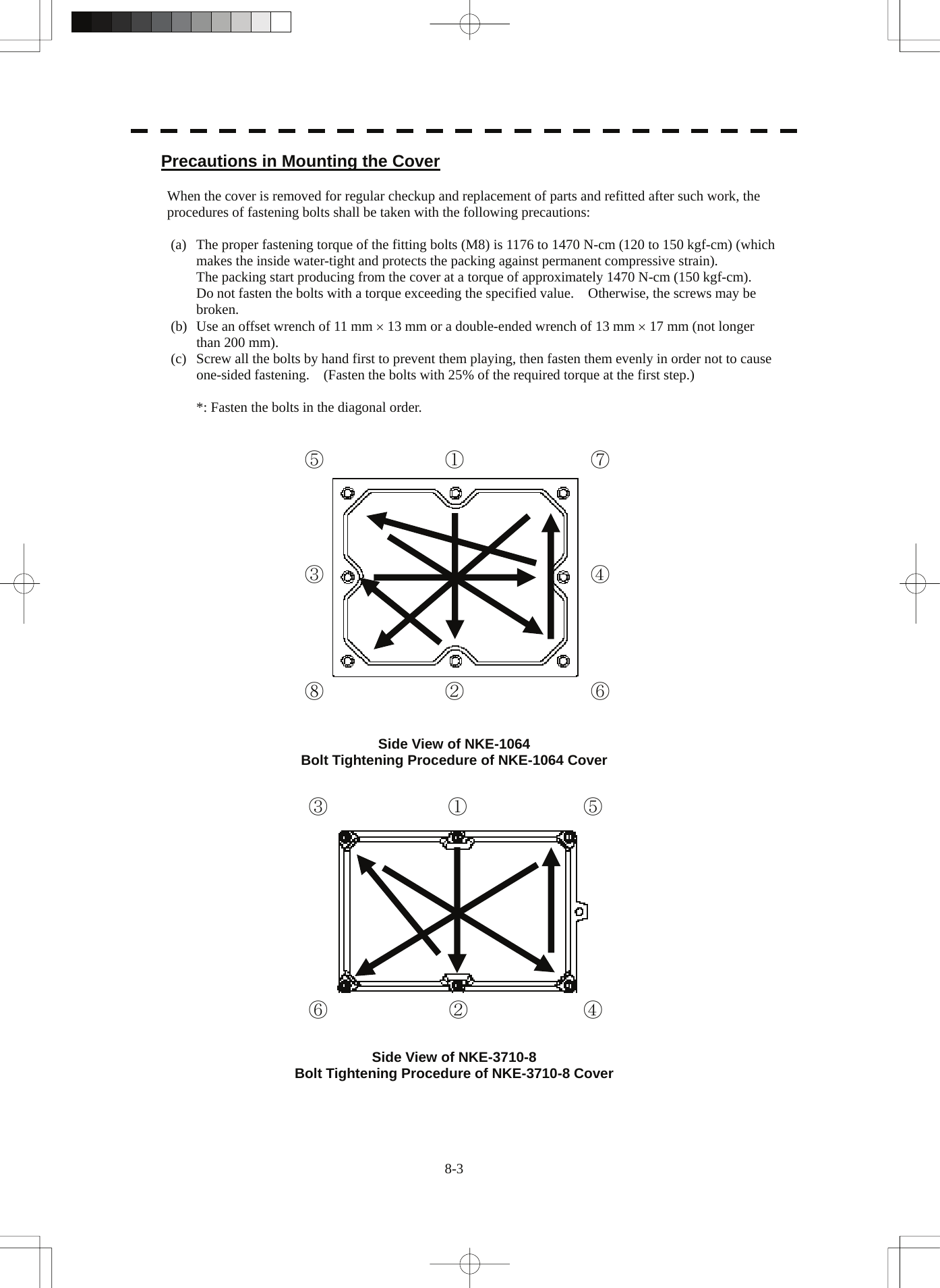
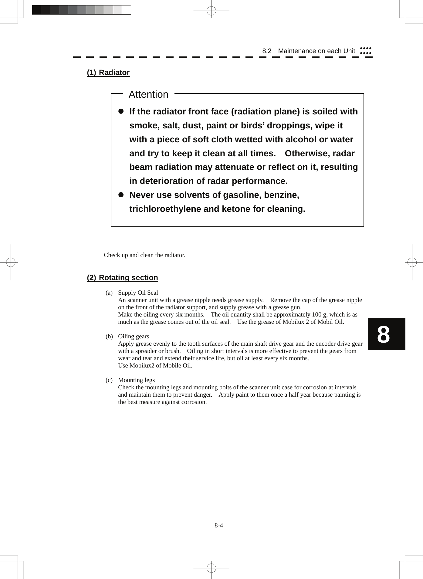
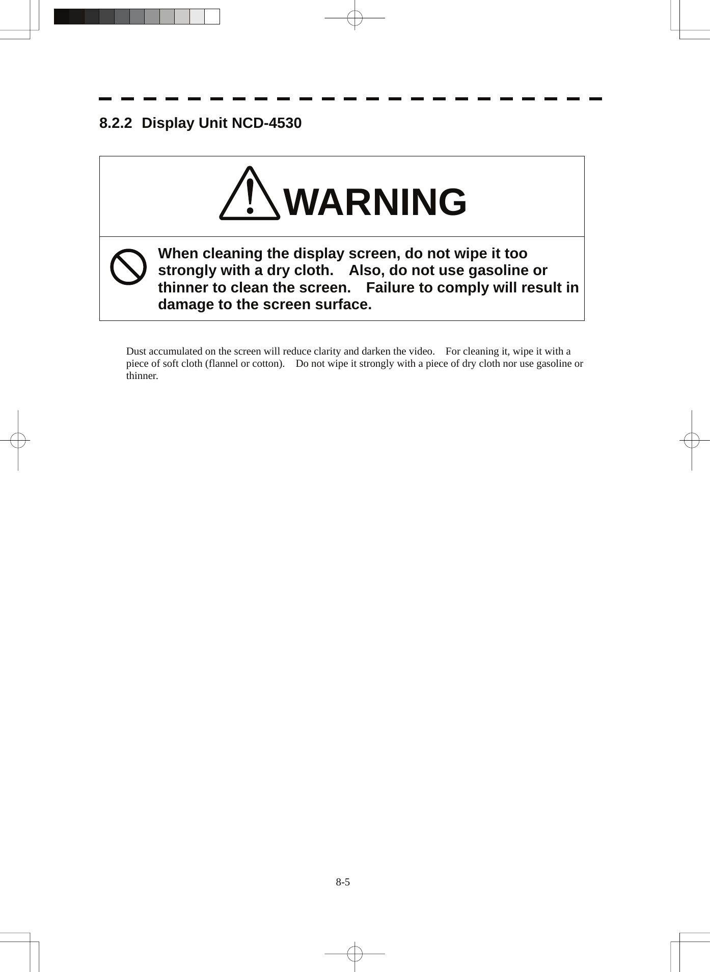
![8-6 8.3 Performance Check yyyyyyyy8 8.3 PERFORMANCE CHECK Make operational check on the radar equipment regularly and if any problem is found, investigate it immediately. Pay special attention to the high voltage sections in checking and take full care that no trouble is caused by any error or carelessness in measurement. Take note of the results of checking, which can be used effectively in the next check work. Operational check shall be made in accordance with Table 8-1 Function Check List in the order as specified in it. Table 8-1 Check List Equipment Item to be checked Criteria Remarks Transmitter-receiver Unit (NKE-1064) Tuning LED of Receiver The LED is lighting during operation 48NM range Video and echoes on the screen Sensitivity LCD brilliance can be controlled correctly Various markers Various numerical indications Lighting Can be correctly controlled Memory See section 8.3.1 [I]-[1]. Communications Lines See section 8.3.1 [I]-[3]. Power Supply, Backup Battery See section 8.3.1 [I]-[4]. Monitor See section 8.3.1 [II]. Operation Unit See section 8.3.1 [III]. System Alarm Log Display See section 8.3.1 [V]. System Information Display See section 8.3.1 [VI]. Magnetron current See section 8.3.1 [VII]. Display Unit Target Tracking See section 5.2.7. Scanner Unit Signals from the Scanner Unit See section 8.3.1 [I]-[2].](https://usermanual.wiki/Japan-Radio/NKE3710.User-Manual-3/User-Guide-2120533-Page-143.png)
![8-7 8.3.1 Check Performance on Test Menu The radar operating state can be checked by opening the Test Menu. Procedures 1. Perform the following menu open procedure to open the Test Menu. Main → 9. NEXT → 9. Test Menu 2. Select the items to be checked. The list of check items will appear. 1. Self Test [I] Self-diagnostic function 2. Monitor Test [II] Monitor check 3. Keyboard Test [III] Operation unit check 4. MON Display [IV] Performance monitor 5. System Alarm Log [V] Error log display 6. System Information [VI] System information display Magnetron Current [VII] Indication of magnetron current 3. Select the items to be checked. The list of check items will appear. [I] Self-diagnosis function (Self Test) Check of memory, scanner unit, and communications Lines 1. Memory Test [1] Memory check 2. TXRX Test [2] Scanner check 3. Line Test [3] Communication line check 4. Supply Voltage [4] Supply voltage check [1] Memory Test Checks for the performance of built-in memory. 1. SDRAM [1] SDRAM check 2. SRAM [2] SRAM check 3. FLASH ROM [3] Flash ROM check 4. GRAPHIC [4] Graphic check When no abnormality is found, OK is displayed. When an abnormality is found, NG is displayed.](https://usermanual.wiki/Japan-Radio/NKE3710.User-Manual-3/User-Guide-2120533-Page-144.png)
![8-8 8.3 Performance Check yyyyyyyy8 [2] TXRX Test Checks for signals from the scanner. Safety Switch Scanner’s safety switch check AZI Pulse Scanner rotation signal check HL Pulse Heading line signal check MH Current Check on the load current of high voltage in the modulator Trigger Radar trigger signal check Video Radar video check When no abnormality is found, OK is displayed. When an abnormality is found, NG is displayed. In standby, ** will appear. [3] Check of Communication Lines (Line Test) Check the status of communications with options. TXRX Check on connection with the transmitter-receiver SIG.PROC Check on connection with the signal processing circuit TT Check on connection with the target tracking unit GYROO I/F Check on connection with the GYRO I/F unit GPS Compass Check on connection with the GPS compass ISW Check on connection with the interswitch Plotter Key Check on connection with the plotter option When no abnormality is found, OK is displayed. When an abnormality is found, NG is displayed. The status display field of equipment not connected is left blank. [4] Supply Voltage Check the voltage of internal power supply. Item Normal value 12V 11.00-12.20 V 5V 4.75-5.25 V 3.3V 3.14-3.46 V Battery 2.50V or more](https://usermanual.wiki/Japan-Radio/NKE3710.User-Manual-3/User-Guide-2120533-Page-145.png)
![8-9 [II] Monitor Test Checks for the display. The test pattern will be shown on the display. Pattern 1 All colors are filled with white. Pattern 2 A white box is displayed on the black background of 1280 × 1024 dots. Pattern 3 Displays rectangle × 2, circle × 2, and cross-shape× 13 (white lines on the black background). Pattern 4 Displays “H” of 9 dots × 9 dots on the entire screen (white character on the black background). Pattern 5 Gray scale display (16 levels) Pattern 6 Displays a color bar. Pattern 7 Displays the VDR test pattern. Pattern 8 Displays the specified color. To return to the normal display, press any key. If errors occur in the monitor, no test pattern will appear. [III] Keyboard Test (Operation Unit Test) Checks for the controls and switches of the operation panel. 1. Key Test [1] Key check 2. Buzzer Test [2] Buzzer check 3. Light [3] Control panel light check [1] Key Test Checks for the controls and switches of the operation panel. Each key on the operation panel on the display is shown in reverse video at the same time the key is pressed, and the name of the pressed key is displayed. [2] Buzzer Test Checks for the operation panel buzzer. The buzzer will sound. The buzzer automatically stops after it sounds for a specified length of time. [3] Light Test Checks for the control panel light. The brightness of the operation panel is gradually intensified at four levels.](https://usermanual.wiki/Japan-Radio/NKE3710.User-Manual-3/User-Guide-2120533-Page-146.png)
![8-10 8.3 Performance Check yyyyyyyy8 [V] System Alarm Log display Displays previously occurred system alarms with the dates and times when they occurred. The Alarm log display button (2-29P Alarm) is clicked, in the same way as that one. To display the occurrence alarm , press the 1. Display Only Occurrence button. To erase the alarm logs, press the 2. All Clear button. The current alarm is displayed at the lower right of the radar display. For details, refer to Chapter 9. [VI] System INFO Displays the current system information. Indicator Processor software version information TXRX Scanner software version information System No. System number TX Time Total magnetron transmitting time (Total time during which radar was transmitted) X-Band S-Band Motor Time The Motor Time function is unavailable in The JMA-5352-9R and JMA-5362-8R. “0 hours” is always displayed. TXRX Total Time Total operating time of the scanner unit (Total power-on time of the antenna unit) Total Time Total operating time of the display unit (Total power-on time of the display unit) JMA-5352-9R and JMA-5362-8R not display “Motor Time”. [VII] Magnetron Current Displays the Magnetron Current bar indicating the magnetron current to check. When a 48 NM range is set, the magnetron current is normal if the Magnetron Current bar reads the value below. JMA-5352-9R 50 kW: 2-4 scale marks JMA-5362-8R 60 kW: 4-6 scale marks](https://usermanual.wiki/Japan-Radio/NKE3710.User-Manual-3/User-Guide-2120533-Page-147.png)
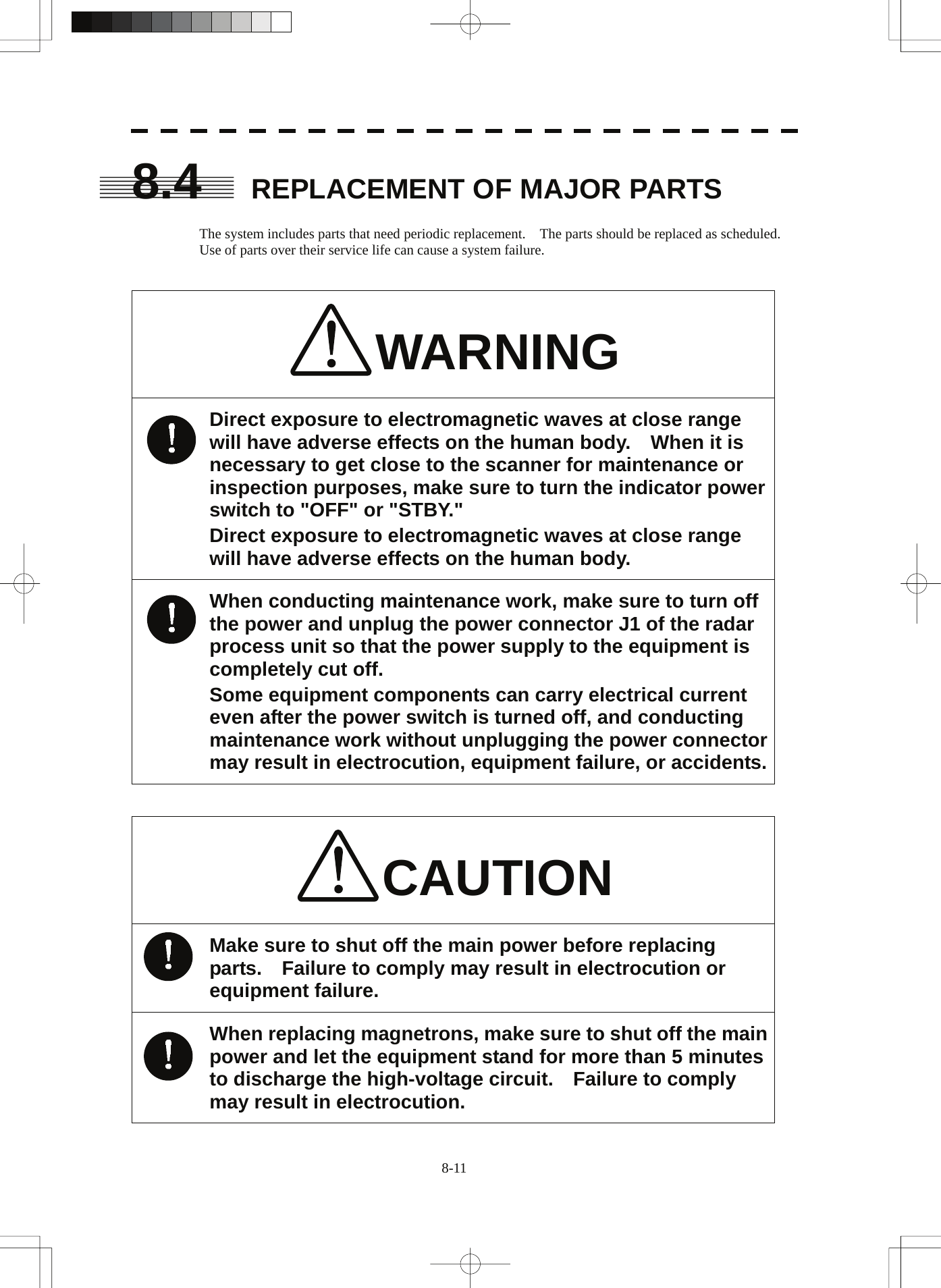
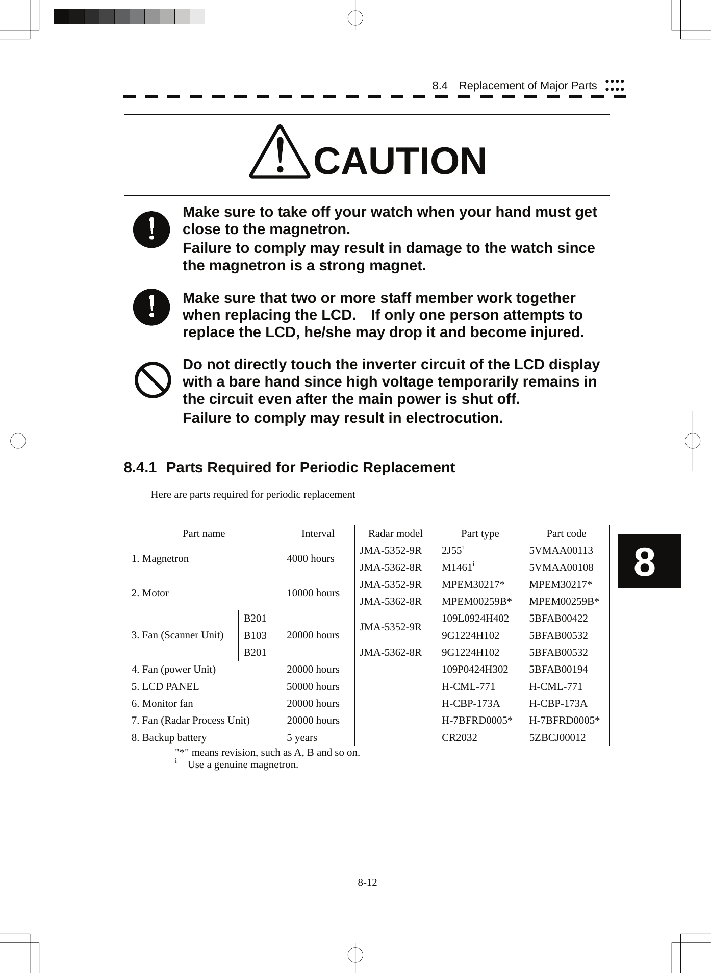
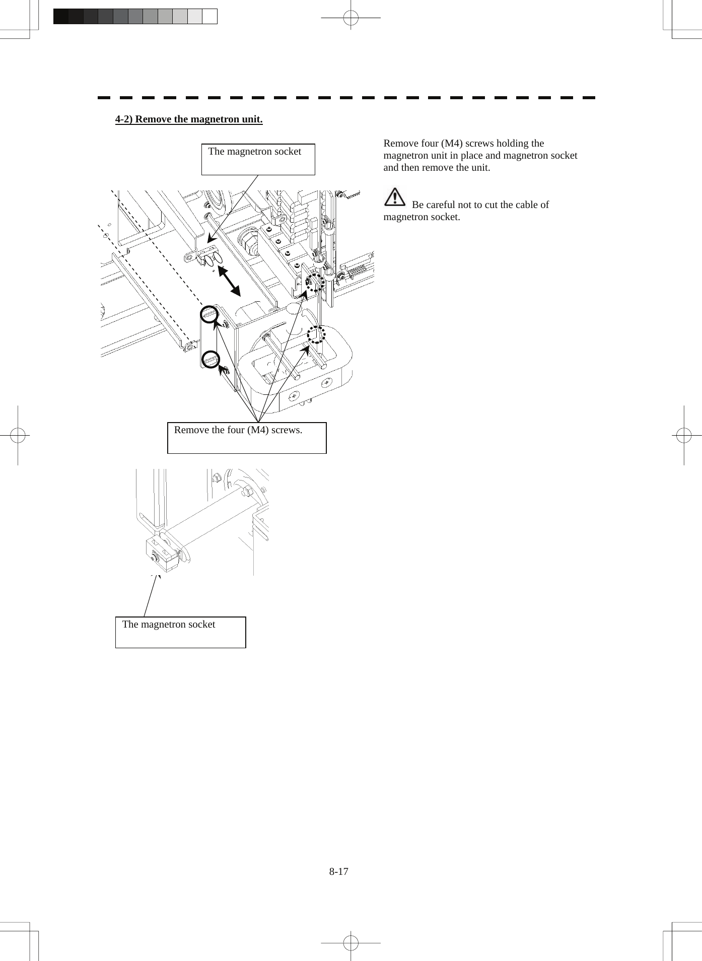
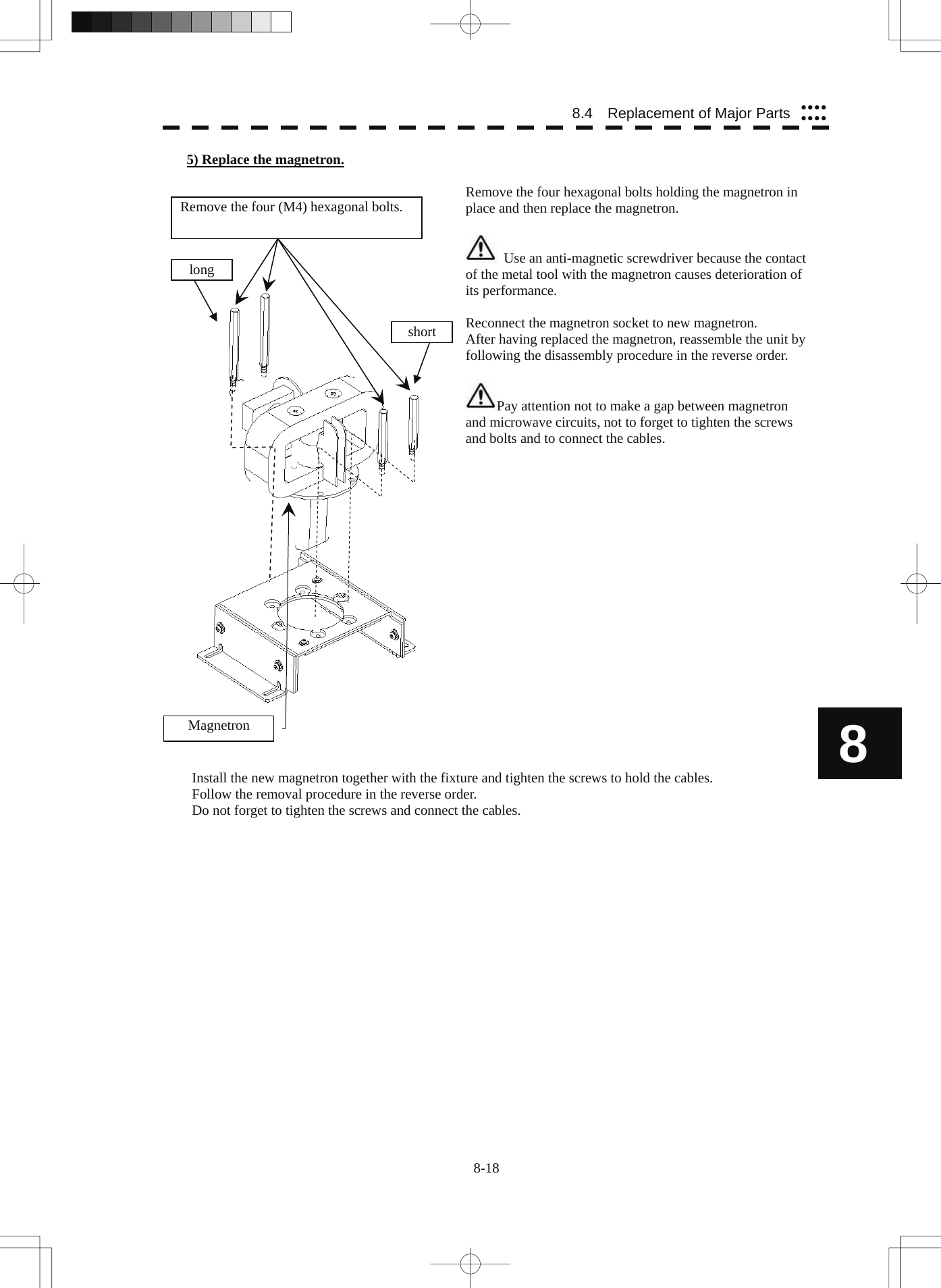
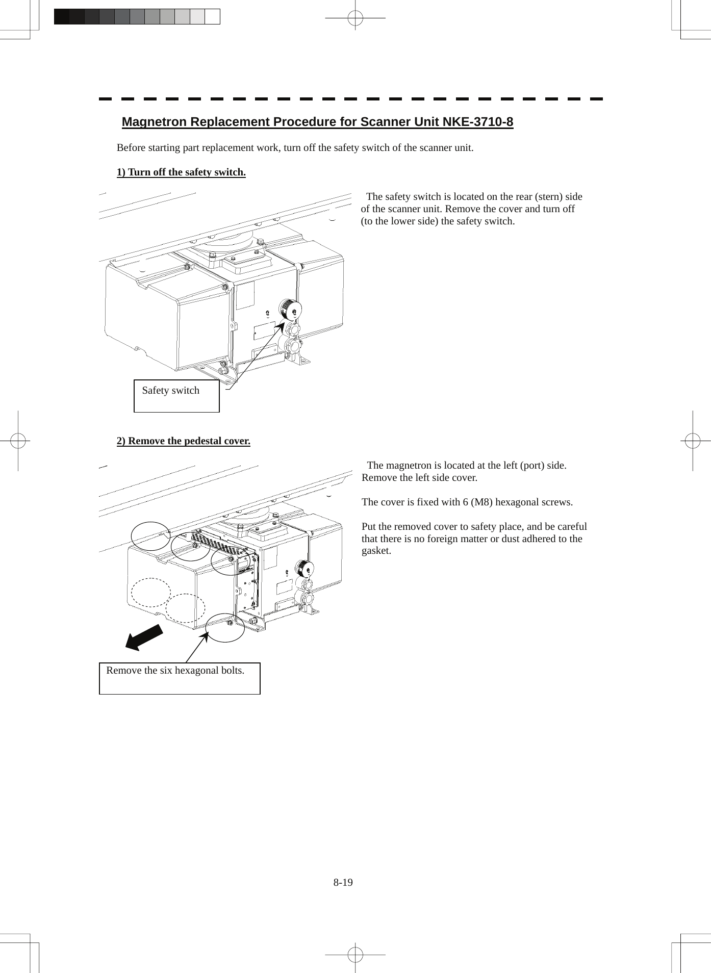
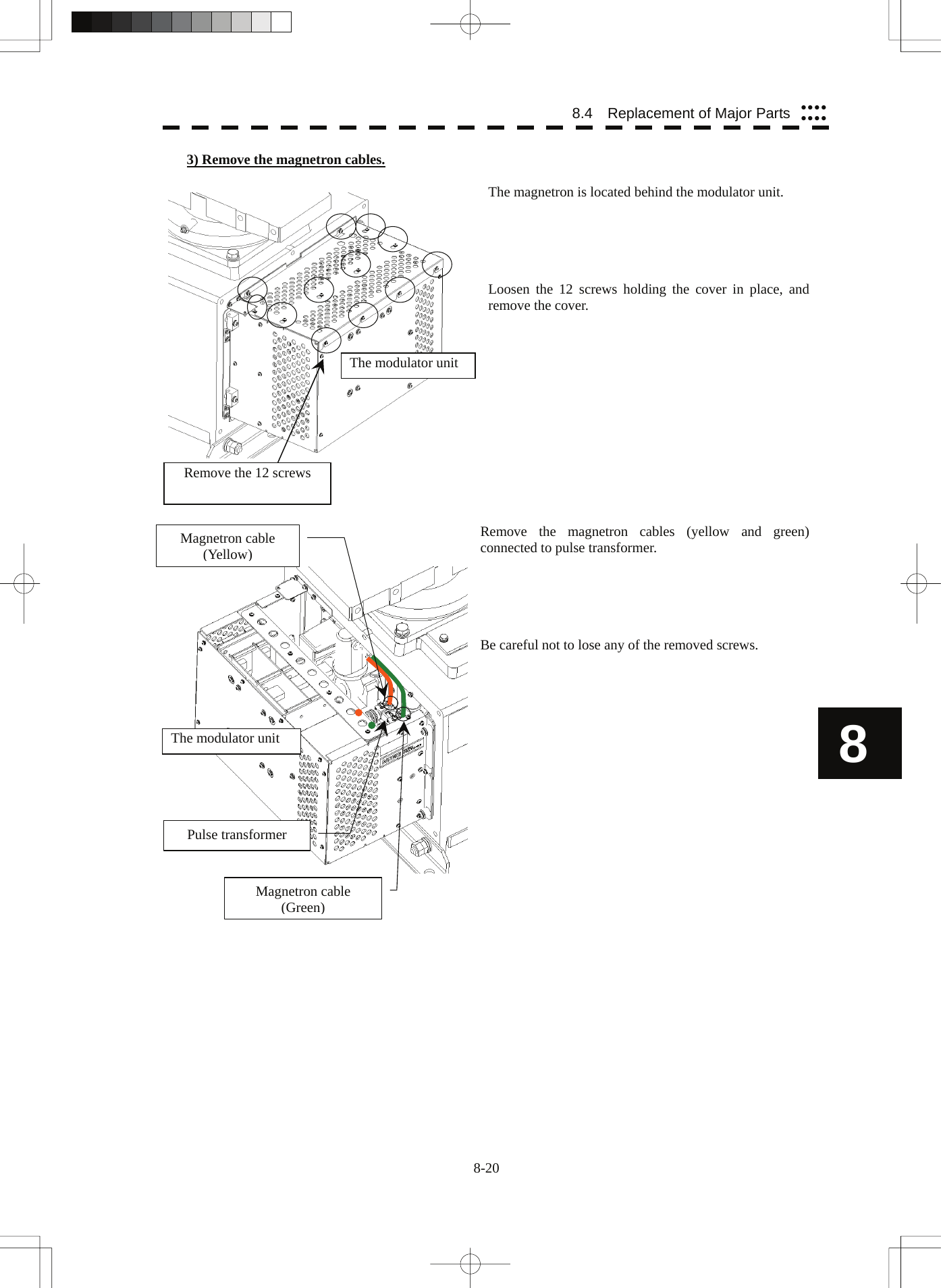
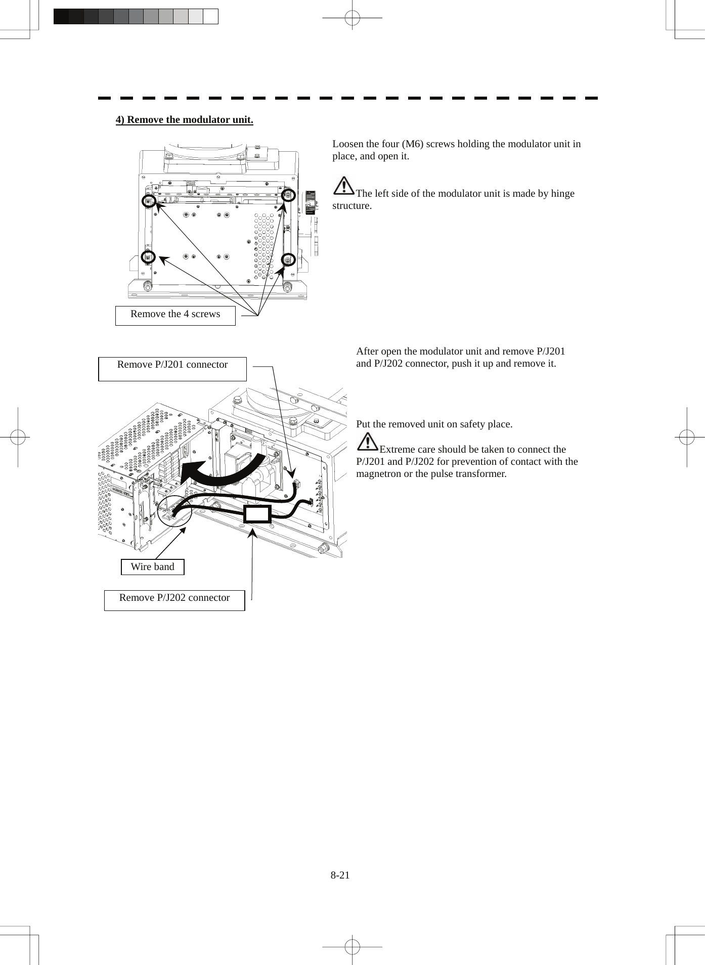
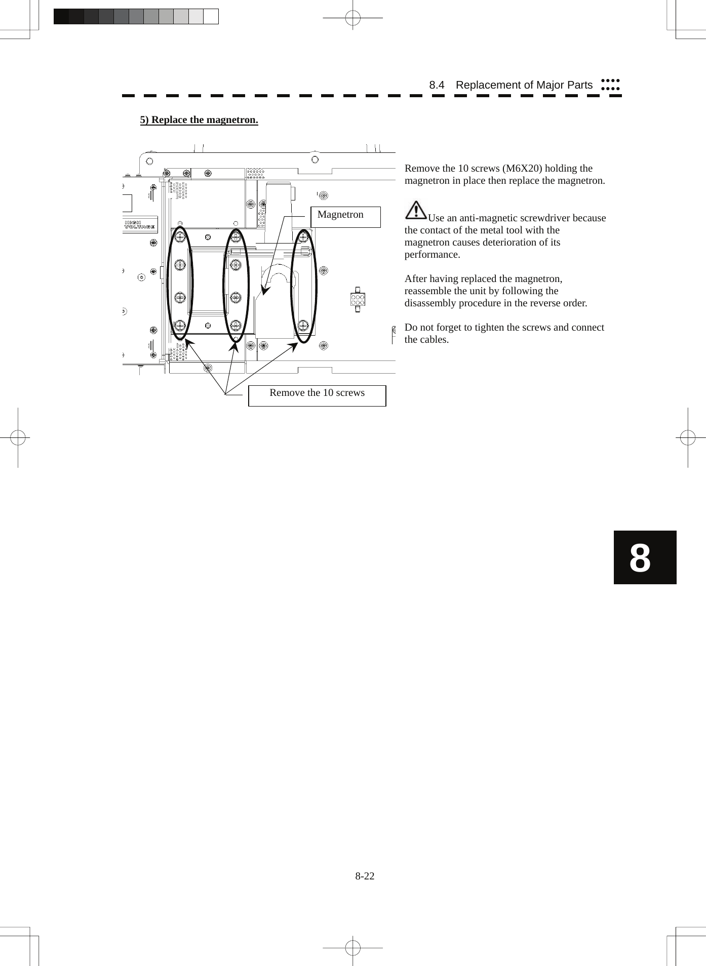
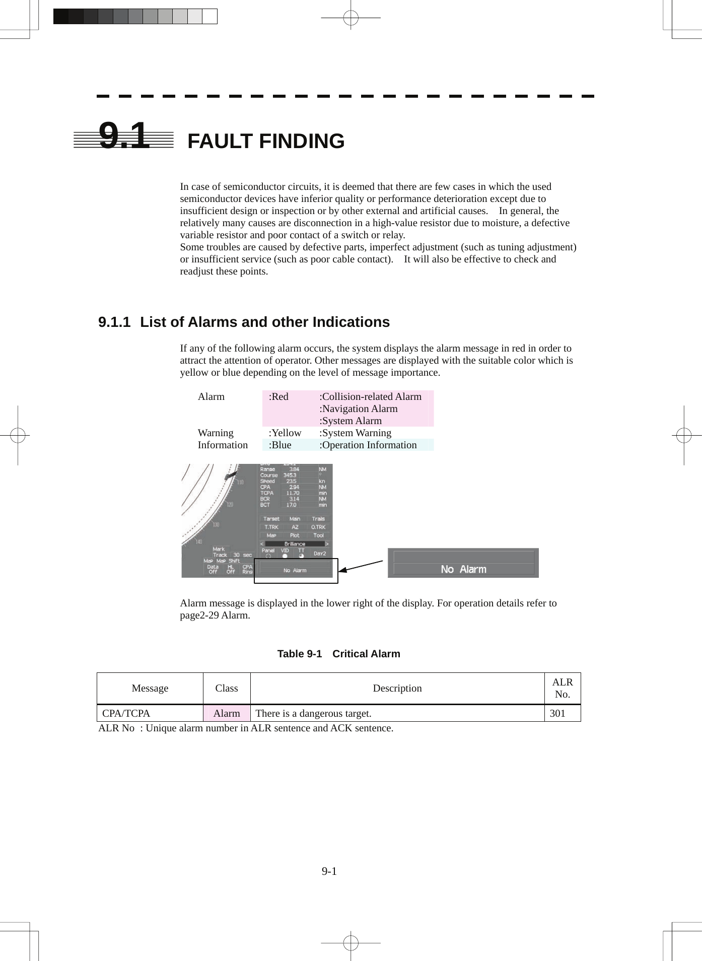
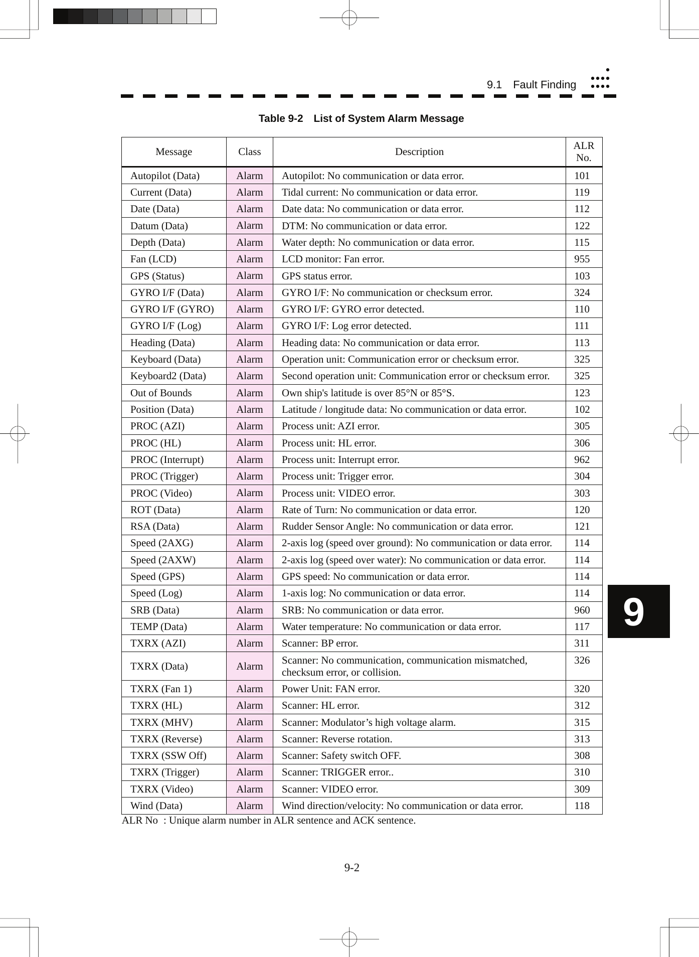
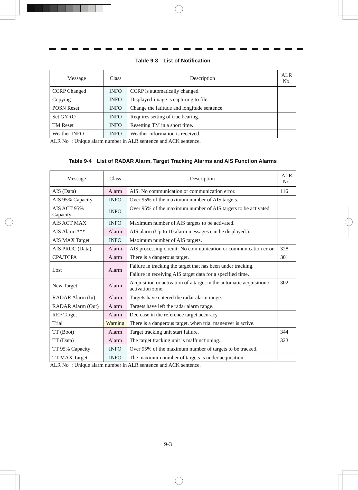
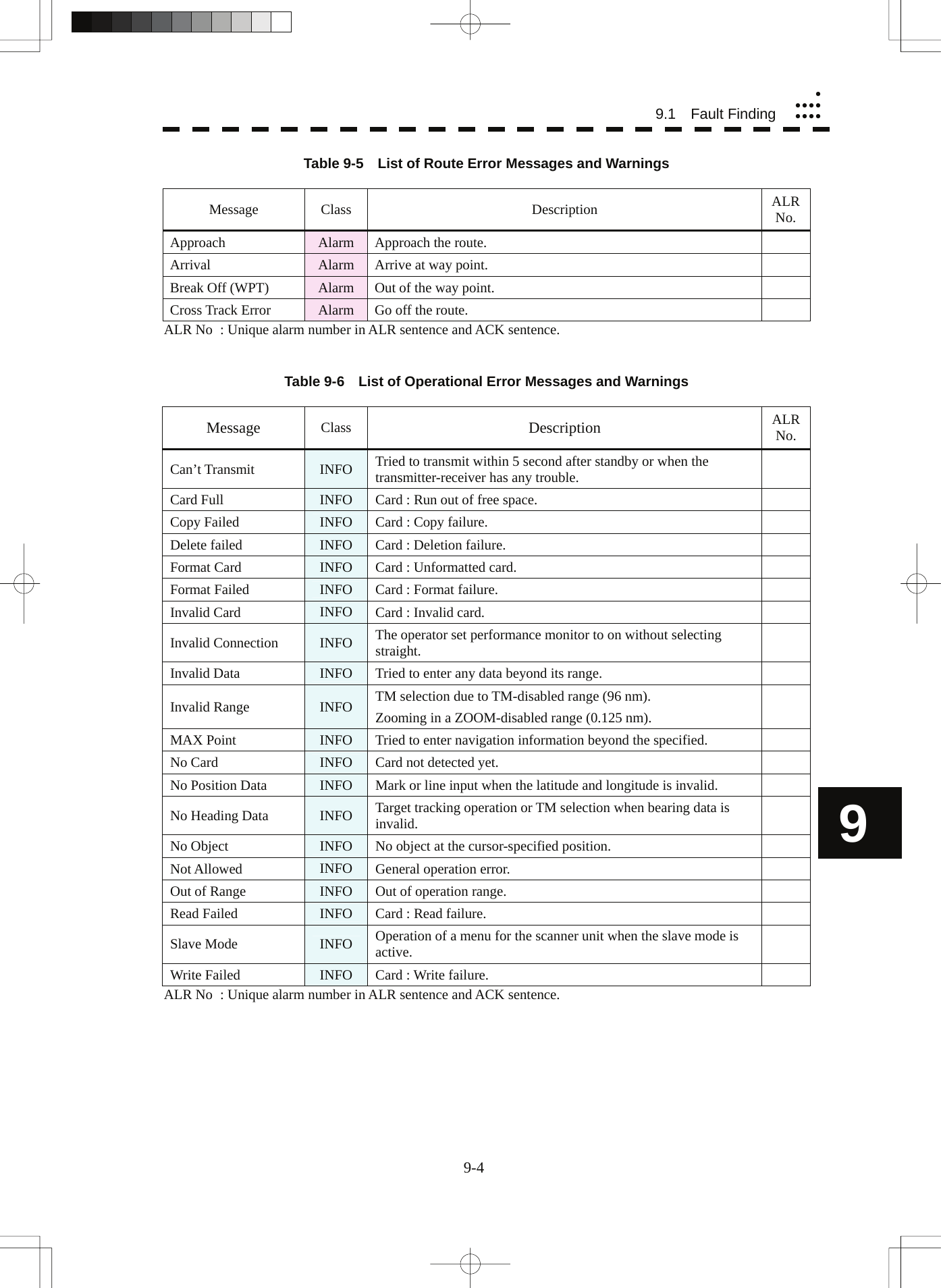
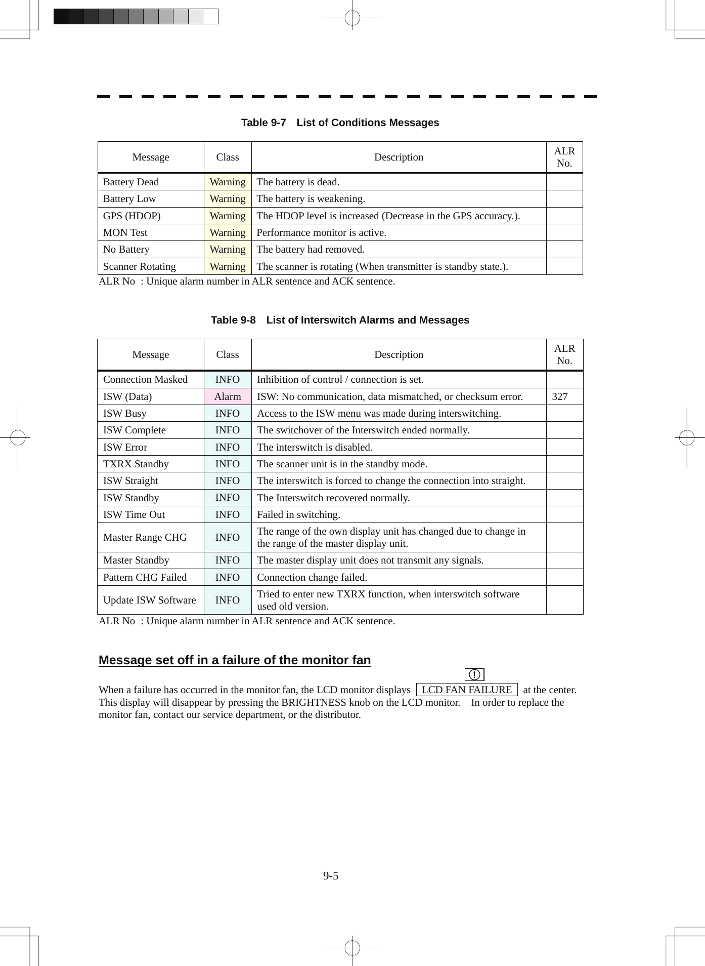
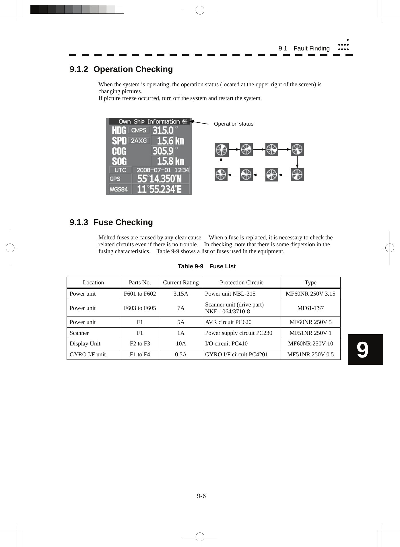
![9-8 9.2 Trouble Shootingyyyyyyyyy9 Table 9-10 Spares (7ZXRD0021, JMA-5352-9R, JMA-5362-8R) 7ZXRD0021 Name Type/Code Shape (mm) In use Spare Parts No. Location Fuse MF60NR 250V 3.15 (5ZFGD00207) 2 6 F601 to F602 Inside power unit Fuse MF61-TS7 (5ZFAA00084) 3 9 F603 to F605 Inside power unit Fuse MF60NR 250V 5 (5ZFGD00208) 1 3 F1 Power unit AVR circuit Fuse MF51NR 250V 1 (5ZFGD00199) 1 3 F1 Scanner power supply circuitFuse MF60NR 250V 10 (5ZFGD00017) 2 6 F2~F3 Inside radar process unit Caution: Use the specified magnetron in table 9-11. Table 9-11 Special Parts [I] JMA-5352-9R Parts No. Name Type Manufacturer Location Code V101 Magnetron 2J55 NJRC Scanner 5VMAA00113 A101 Circulator NJC3901RJ NJRC Scanner 5AJBV00003 A102 TRHPL TL393 NJRC Scanner 5VLAA00029 [II] JMA-5362-8R Parts No. Name Type Manufacturer Location Code V101 Magnetron M1461 NJRC Scanner 5VMAA00108 A101 Circulator NJC-3314 NJRC Scanner NJC-3314 A102 TRHPL TL378A NJRC Scanner 5VLAA00037 30 Φ6.420 Φ5.230 Φ6 32 Φ6.430 Φ6.4](https://usermanual.wiki/Japan-Radio/NKE3710.User-Manual-3/User-Guide-2120533-Page-171.png)
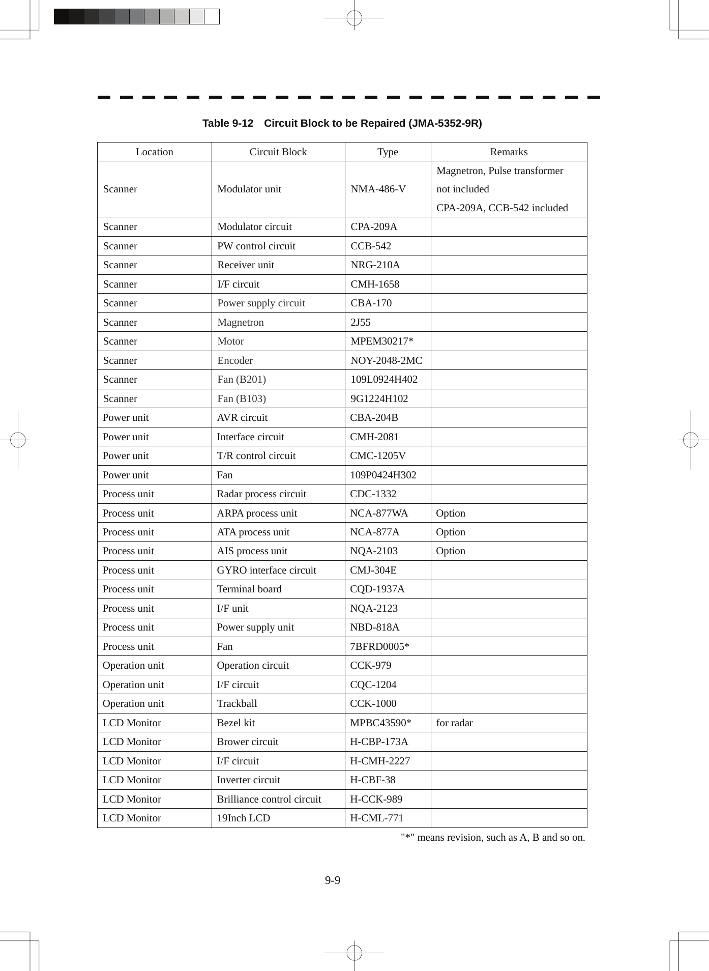
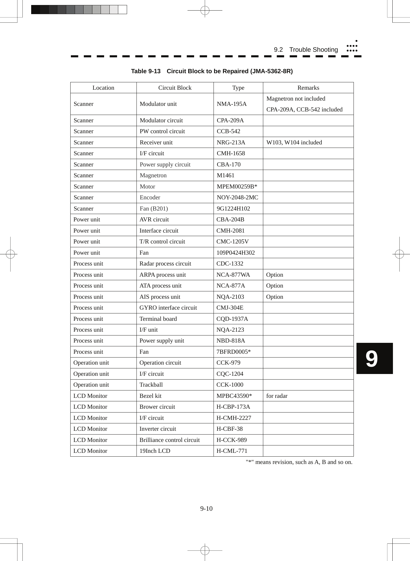
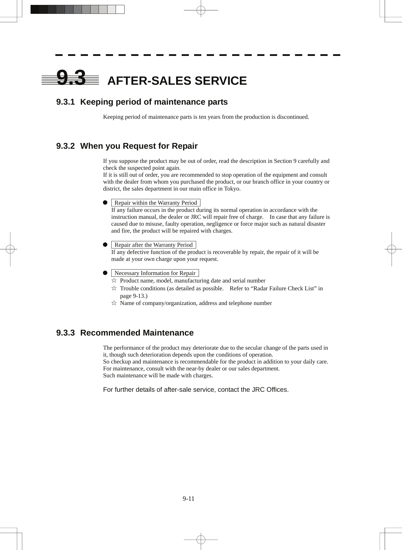
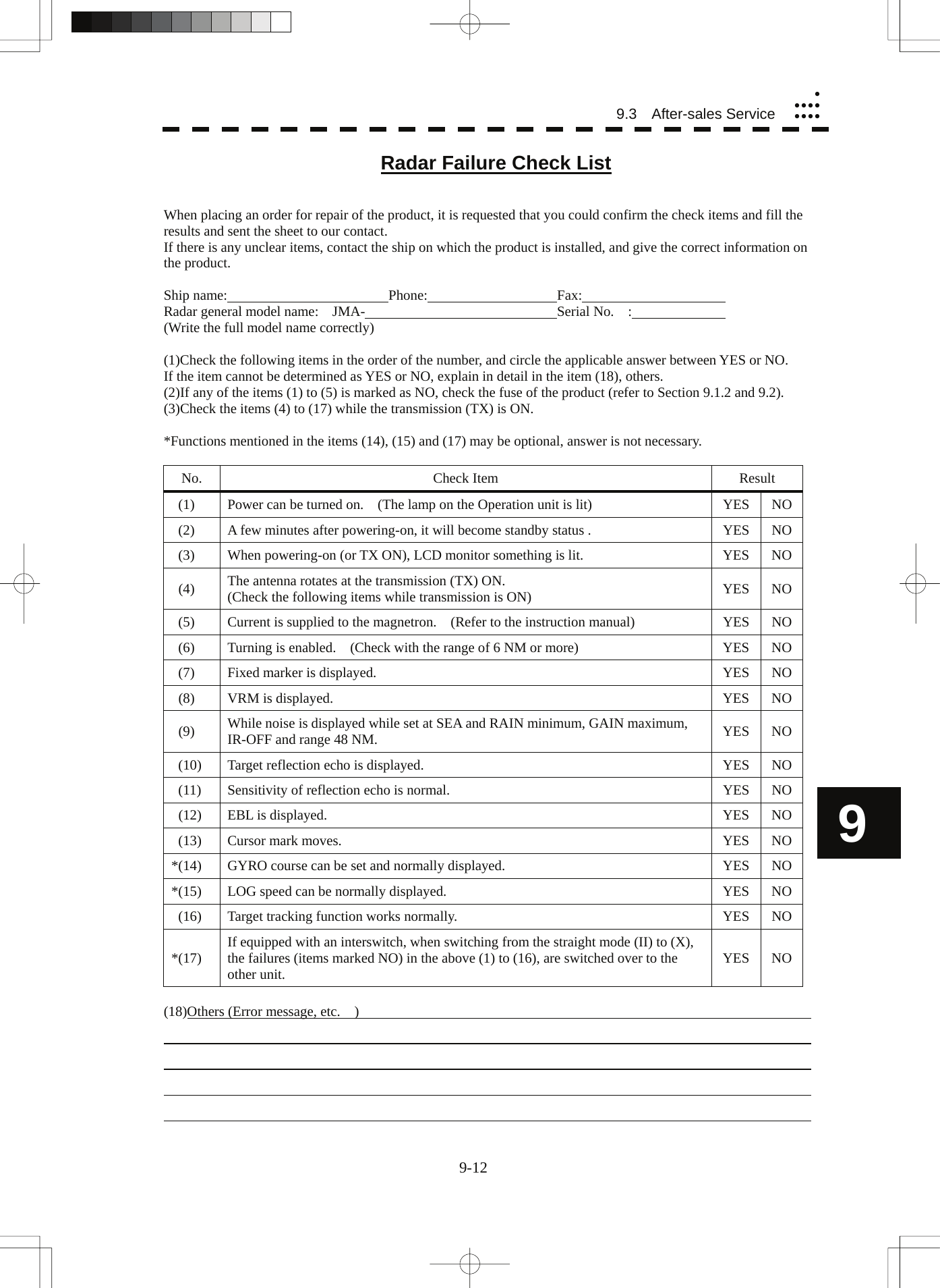
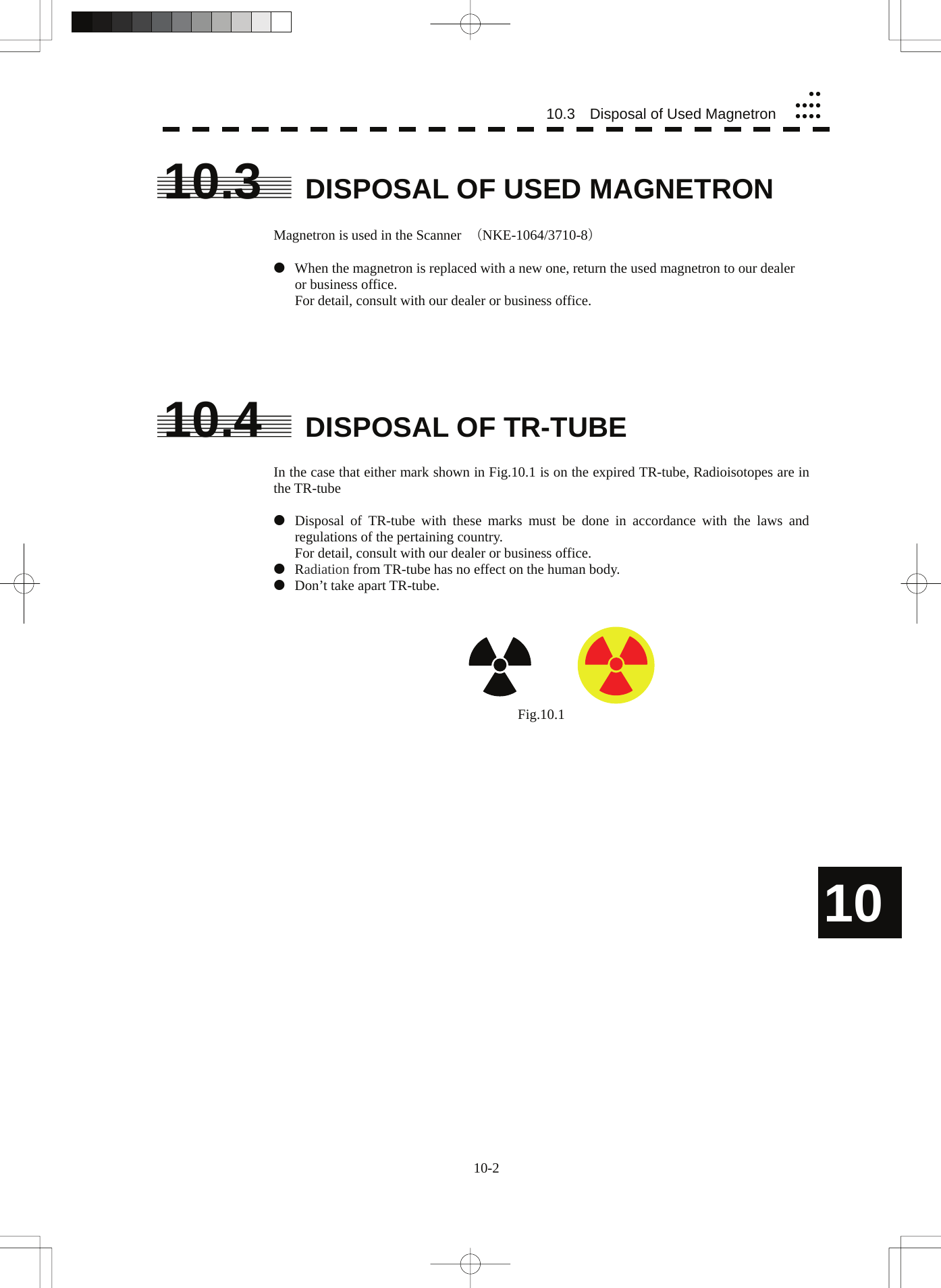
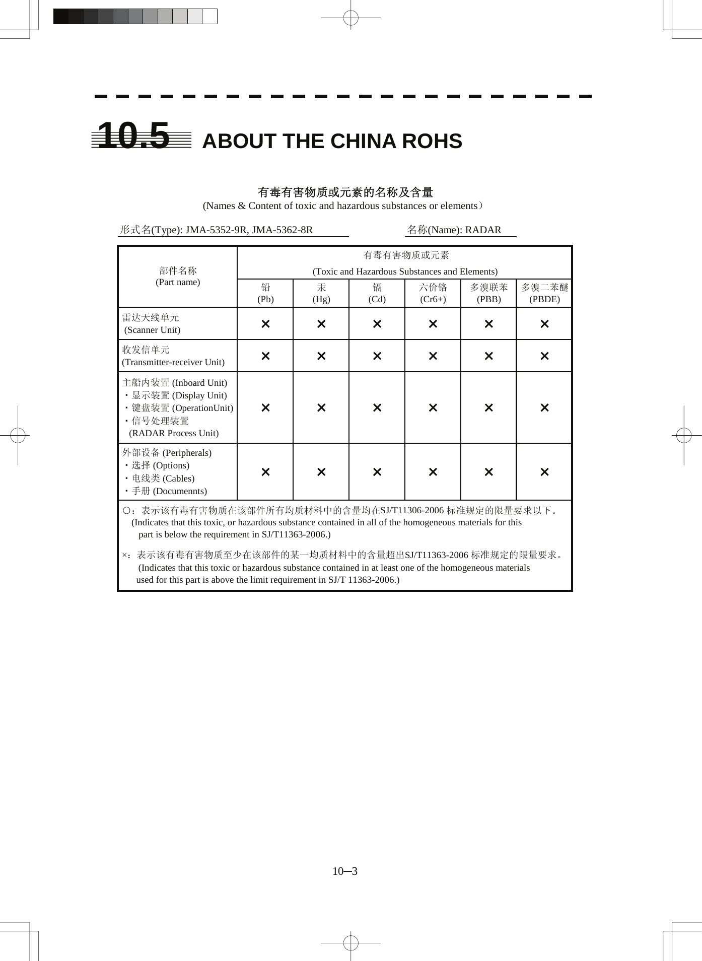
![11-2 11.2 Scanner (NKE-1064)yyyyyyyyyyy11 11.2 SCANNER UNIT (NKE-1064) (1) Dimensions Height 714 mm × Swing Circle 2806 mm (2) Mass Approx. 100 kg (3) Polarization Horizontal Polarization (4) Directional Characteristic Horizontal Beam Width: 0.8 ° (-3 dB width) Vertical Beam Width: 20 ° (-3 dB width) Sidelobe Level: Below -26dB (within ±10 °) Below -30dB (outside ±10 °) (5) Revolution Approx. 17/14 rpm (60/50 Hz) (6) Peak Power 50 kW ±5 0% (7) Transmitting Frequency 9375 ±30 MHz (8) Transmitting Tube Magnetron [2J55] (9) Pulse width/Repetition Frequency SP1: 0.08 μs/1700 Hz MP1: 0.25 μs/1700 Hz LP1: 0.75 μs/860 Hz, LP2: 1.0 μs/650 Hz 0.125 NM SP1 0.25 NM SP1 0.5 NM SP1 0.75 NM SP1 / MP1 (1 NM) SP1 / MP1 1.5 NM SP1 / MP1 / LP1 (2 NM) SP1 / MP1 / LP1 3 NM SP1 / MP1 / LP1 (4 NM) SP1 / MP1 / LP1 6 NM MP1 / LP1 / LP2 (8 NM) MP1 / LP1 / LP2 12 NM MP1 / LP1 / LP2 (16 NM) MP1 / LP1 / LP2 24 NM LP2 (32 NM) LP2 48 NM LP2 96 NM LP2 (10) Duplexer Circulator + TRHPL (11) Mixer MIC Front End (12) Intermediate Frequency Amplifier Intermediate Frequency: 60 MHz Band Width: 20 MHz (0.08 μs) 6 MHz (0.25 μs) 3 MHz (0.75 μs, 1 μs) Gain: More than 90 dB Amplifying Characteristics: Logarithmic Amplifier (13) Overall Noise Figure 7.5 dB (Average)](https://usermanual.wiki/Japan-Radio/NKE3710.User-Manual-3/User-Guide-2120533-Page-183.png)
![11-3 11.3 SCANNER UNIT (NKE-3710-8) (1) Dimensions Height 690 mm × Swing Circle 2730 mm (2) Mass Approx. 98 kg (3) Polarization Horizontal Polarization (4) Directional Characteristics Horizontal Beam Width: 2.7 ° (-3 dB width) Vertical Beam Width 22 ° (-3 dB width) Sidelobe Level: Below -26dB (within ±10 °) Below -30dB (outside ±10 °) (5) Revolution Approx. 17/14 rpm (60/50 Hz) (6) Peak Power 60 kW ±50 % (7) Transmitting Frequency 3050 ±25 MHz (8) Transmitting Tube Magnetron [M1461] (9) Pulse width/Repetition Frequency SP1: 0.08 μs/1700 Hz MP1: 0.25 μs/1700 Hz LP1: 0.75 μs/860 Hz, LP2: 1.0 μs/650 Hz 0.125 NM SP1 0.25 NM SP1 0.5 NM SP1 0.75 NM SP1 / MP1 (1 NM) SP1 / MP1 1.5 NM SP1 / MP1 / MP2 (2 NM) SP1 / MP1 / MP2 3 NM SP1 / MP1 / MP2 (4 NM) SP1 / MP1 / MP2 6 NM MP1 / LP1 / LP2 (8 NM) MP1 / LP1 / LP2 12 NM MP1 / LP1 / LP2 (16 NM) MP1 / LP1 / LP2 24 NM LP2 (32 NM) LP2 48 NM LP2 96 NM LP2 (10) Duplexer Circulator + TRHPL (11) Mixer MIC Front End (12) Intermediate Frequency Amplifier Intermediate Frequency: 60 MHz Band Width (NRG-213): 25 MHz (0.08 μs) 6 MHz (0.25 μs) 3 MHz (0.75 μs, 1 μs) Band Width (NRG-213A): 25 MHz (0.08 μs) 8 MHz (0.25 μs) 3 MHz (0.75 μs, 1 μs) Gain: More than 90 dB Amplifying Characteristics: Logarithmic Amplifier (13) Overall Noise Figure 7.5 dB (Average)](https://usermanual.wiki/Japan-Radio/NKE3710.User-Manual-3/User-Guide-2120533-Page-184.png)
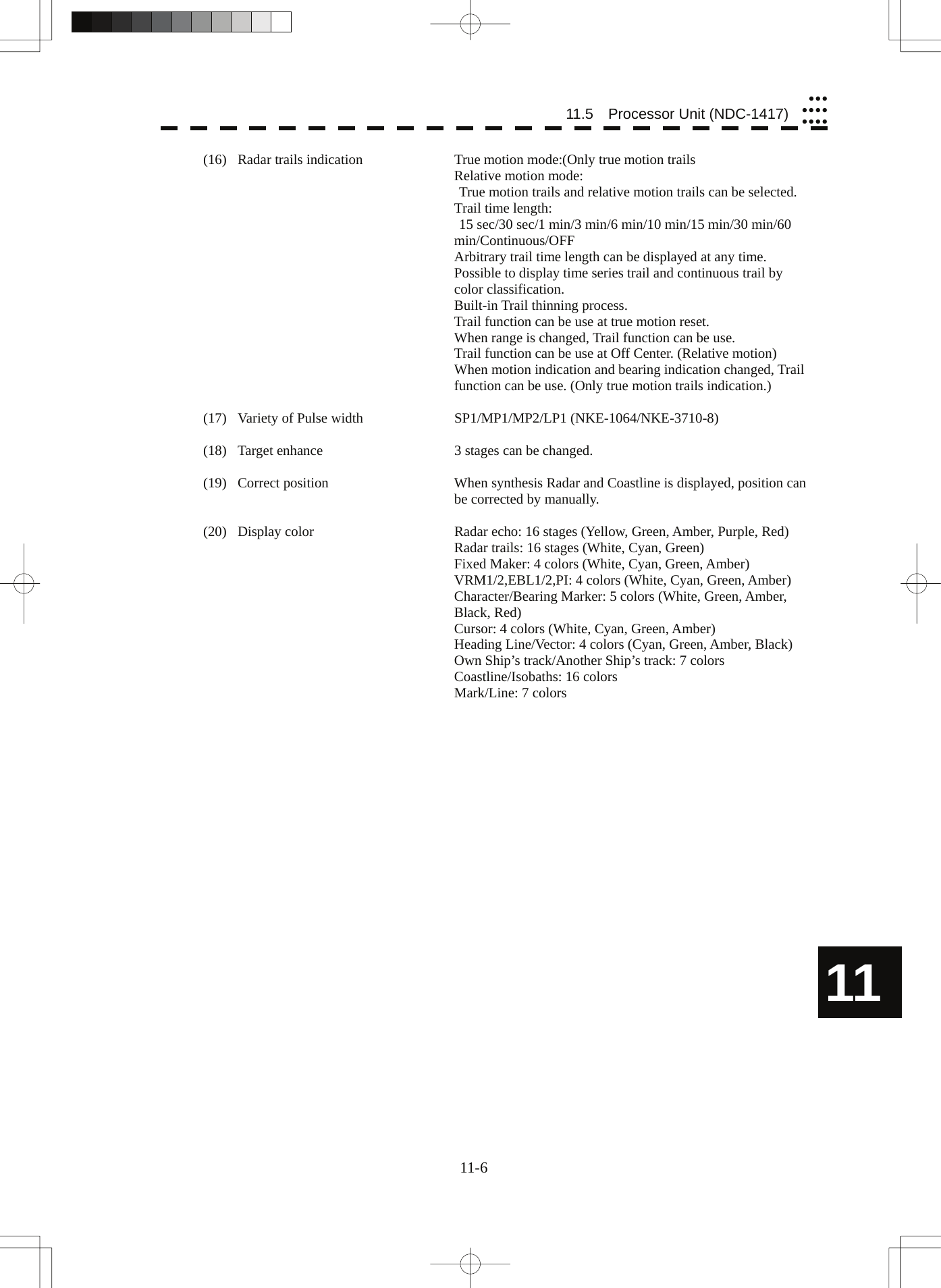
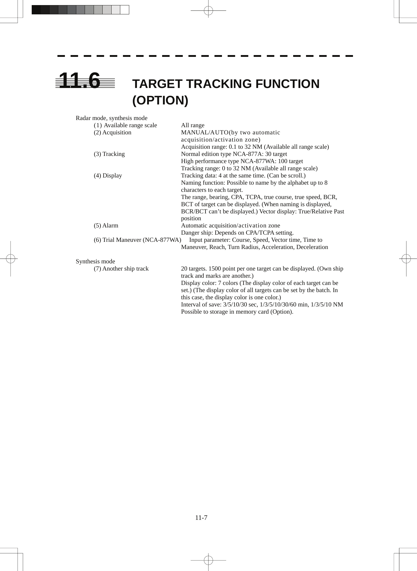
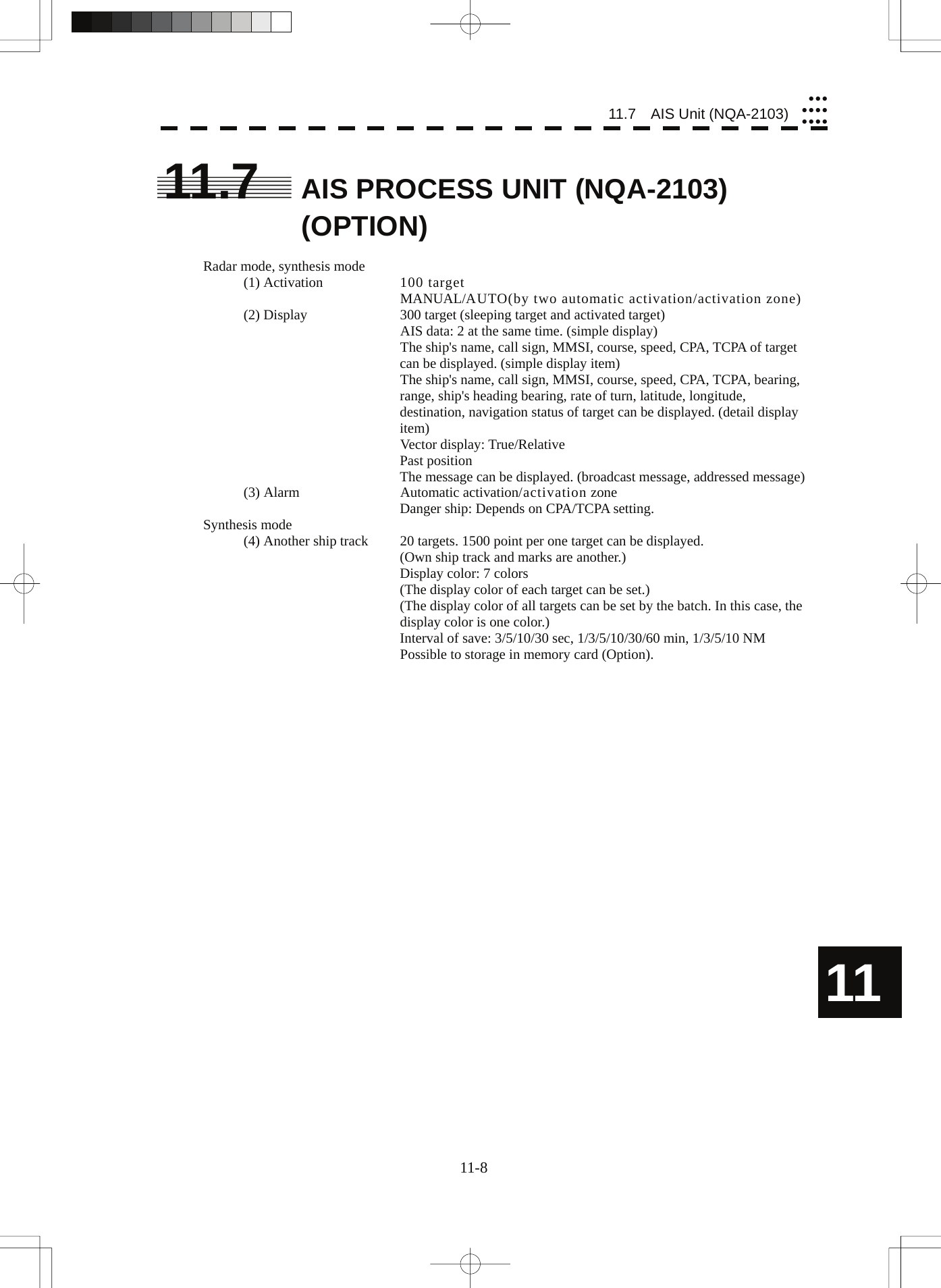
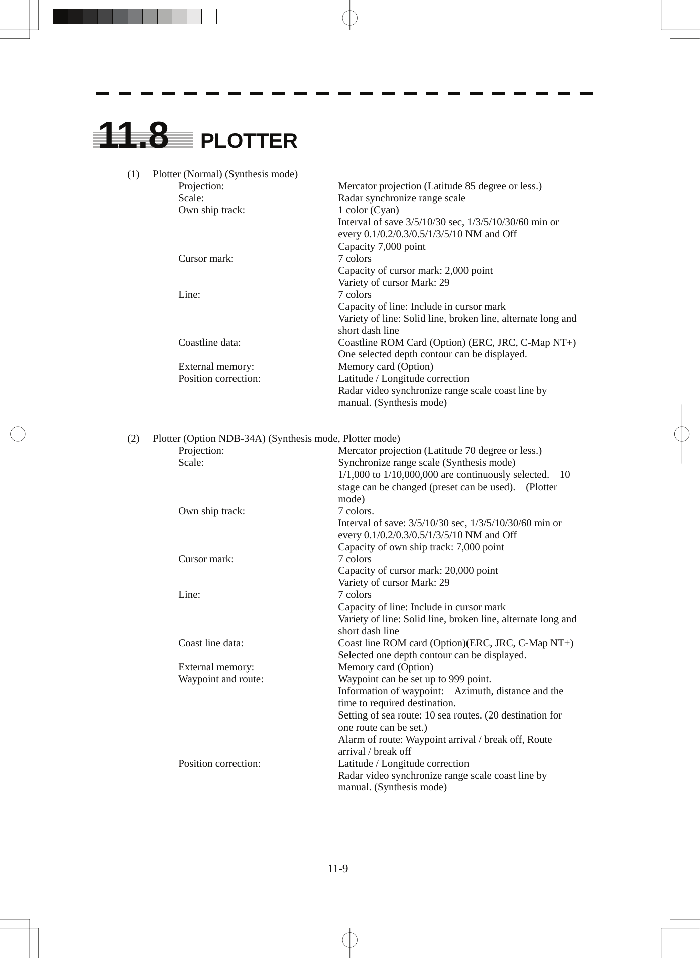
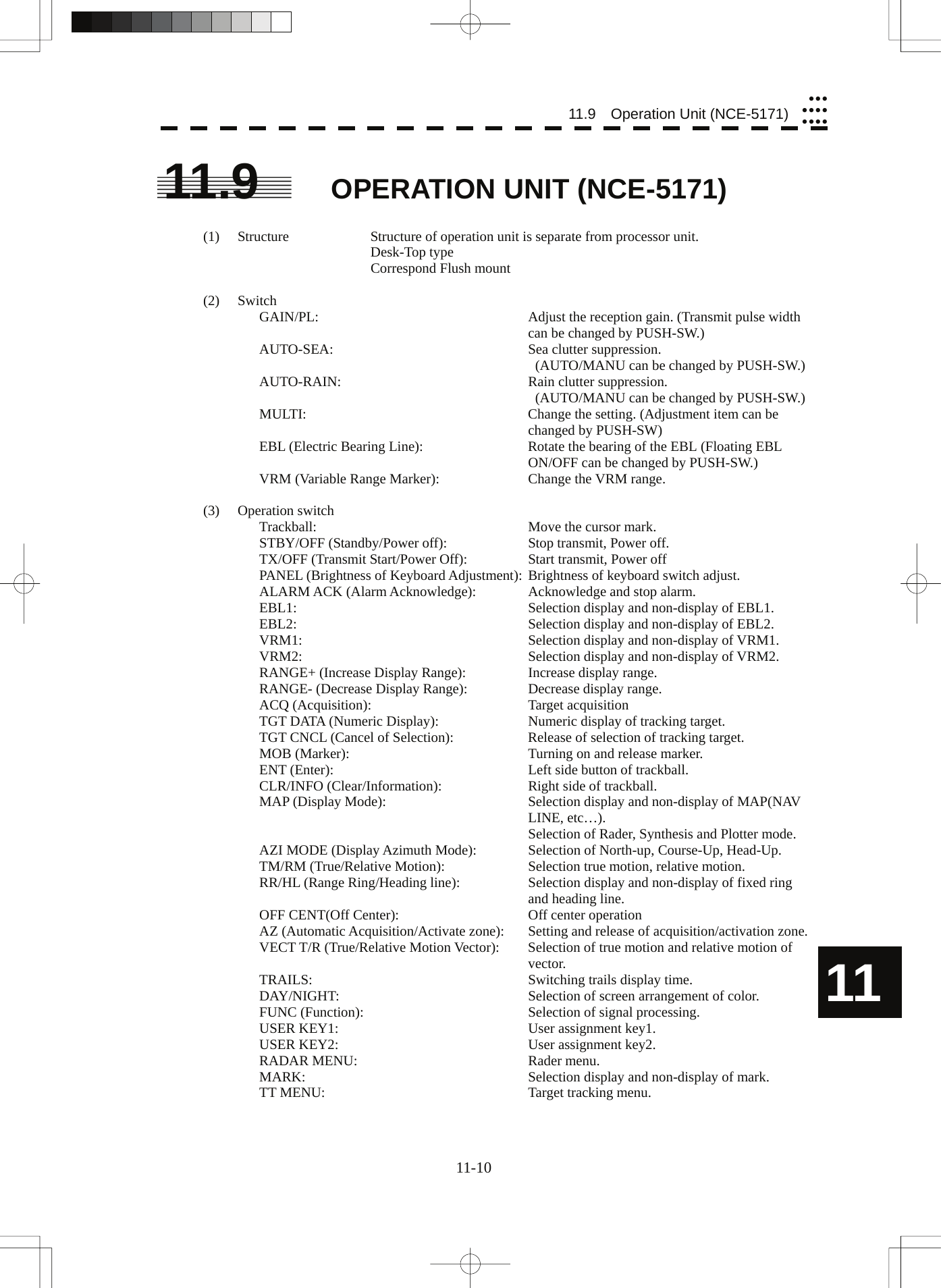
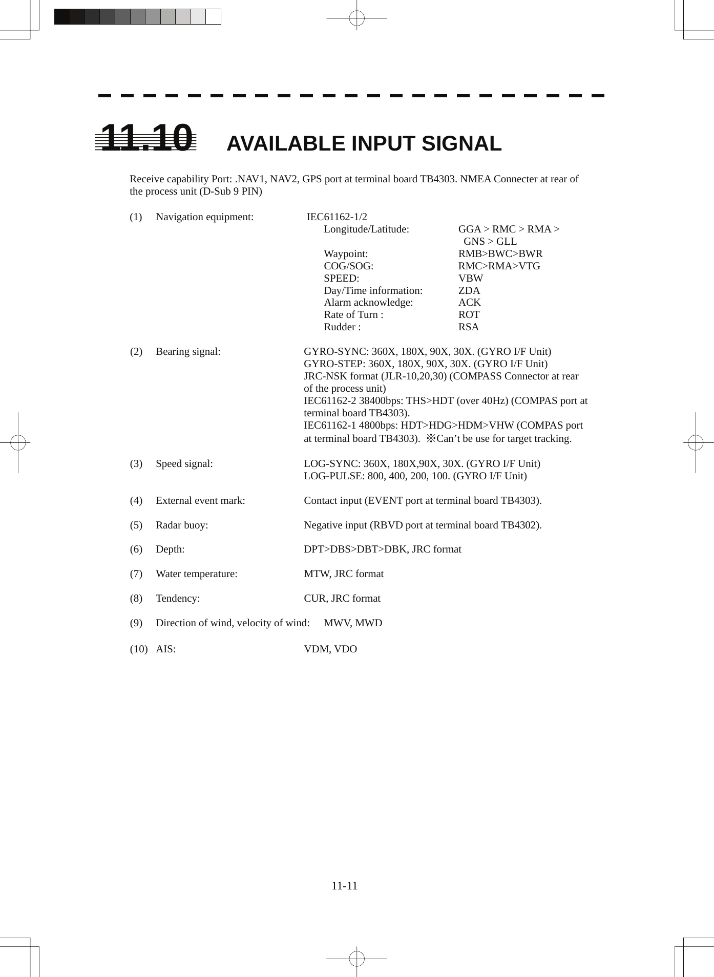
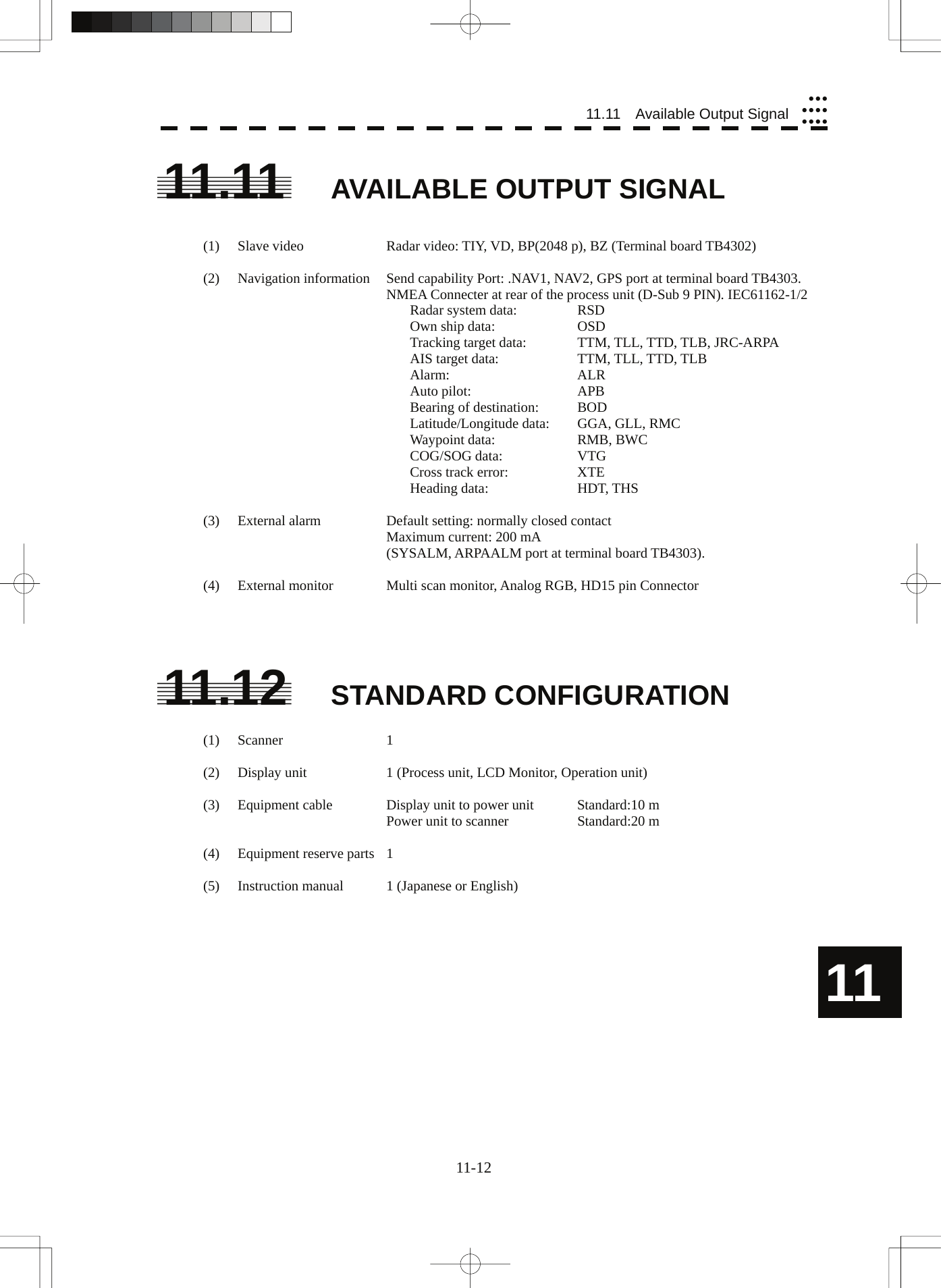
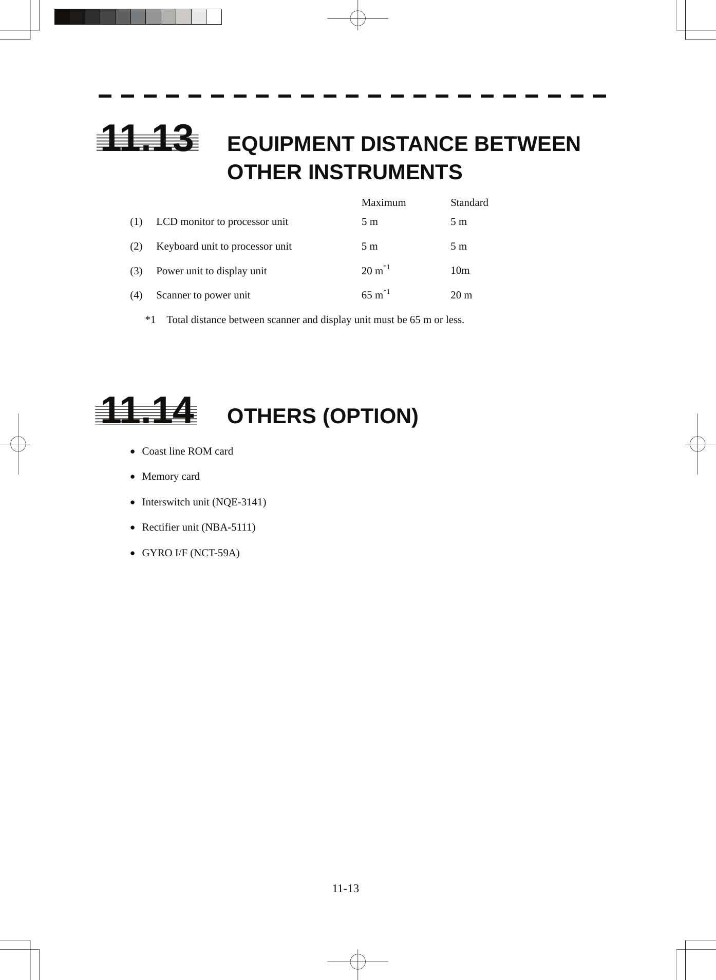

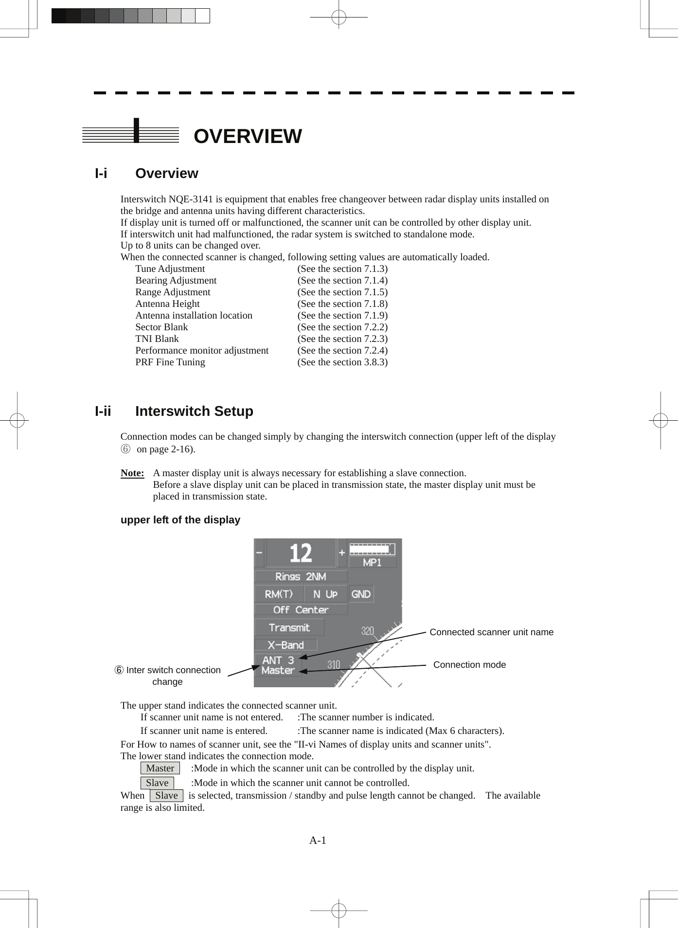
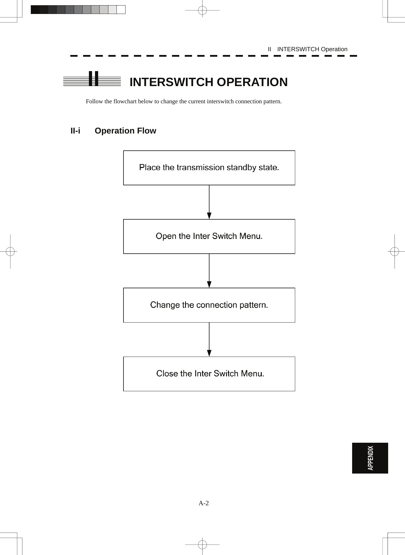
![A-3 II-ii Inter Switch Menu The Inter Switch Menu can be opened only when the transmission standby state. Procedures 1 Press the [STBY] key. The transmission standby state will be placed. 2 Move the cursor onto the Interswitch connection change (upper left of the display ⑥ on page 2-16), and press the [ENT] key. The Inter Switch Menu will appear. Exit 1 Press the [0] key. The Inter Switch Menu will close.](https://usermanual.wiki/Japan-Radio/NKE3710.User-Manual-3/User-Guide-2120533-Page-200.png)
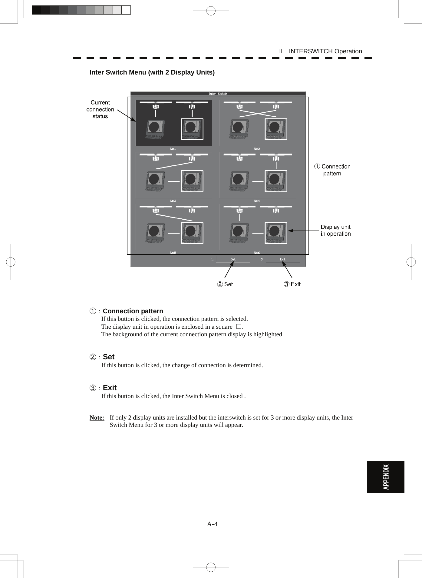
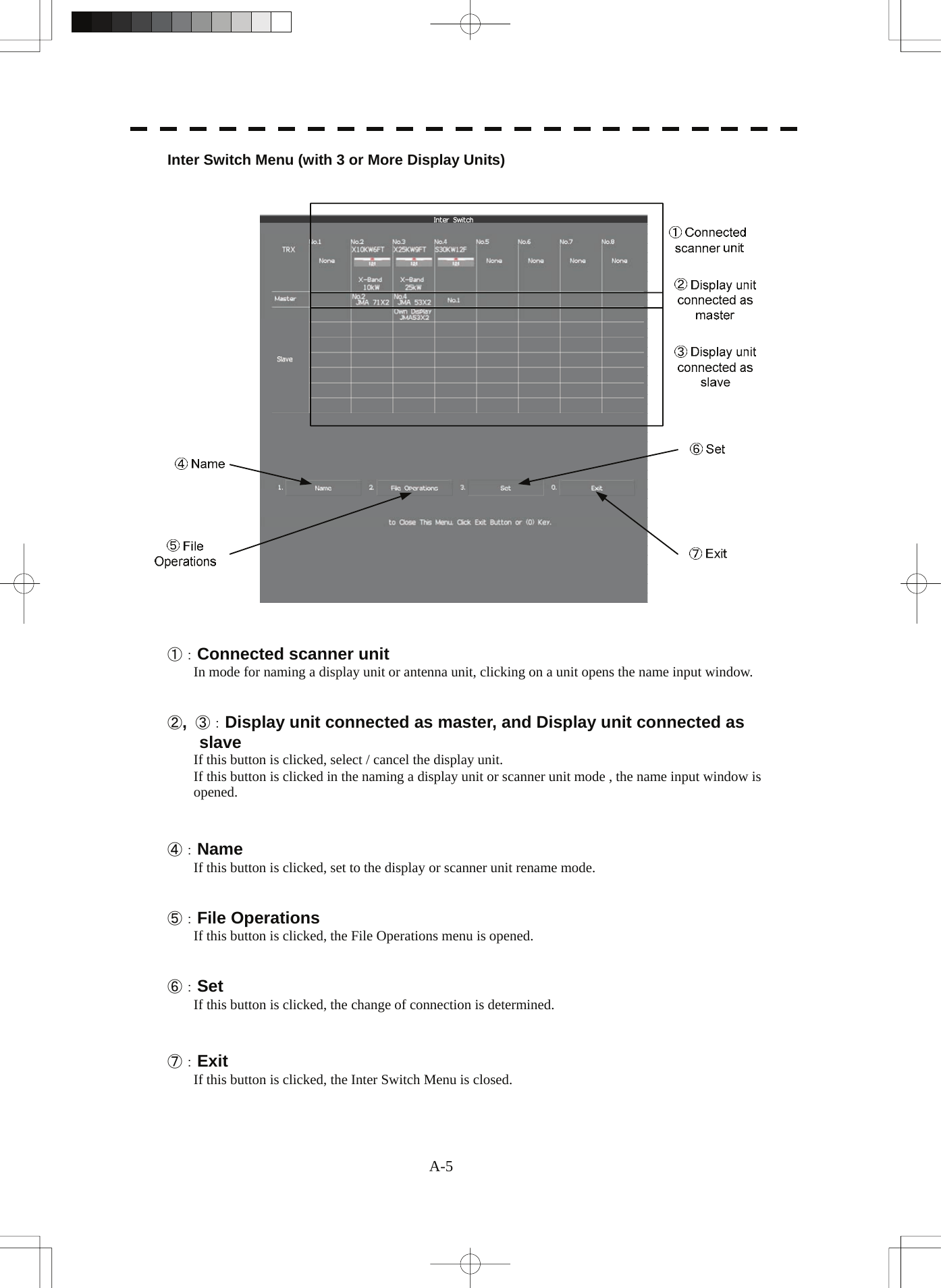
![A-6 II INTERSWITCH Operation APPENDIX II-iii Change of Connection Pattern (with 2 Display Units) If two display units are installed, a connection pattern needs to be selected. Procedures 1 Open the Inter Switch menu (with 2 Display Units). 2 Move the cursor onto the Connection pattern (Inter Switch Menu ① on page A-4) to be changed , and press the [ENT] key. The connection pattern will be selected, and Set (in Inter Switch Menu ② on page A-4) will blink. 3 Press the [3] key. The connection pattern will be changed. II-iv Change of Connection Pattern (with 3 or More Display Units) If three or more display units are installed, the layout of connection patterns needs to be set. Procedures 1 Open the Inter Switch Menu (with 3 or More Display Units). 2 Move the cursor onto the display unit (Inter Switch Menu ②/③ on page A-5) to be changed , and press the [ENT] key. The selected display unit will be highlighted. To deselect the display unit, press the [ENT] key again. 3 Move the cursor to the change-destination display unit, and press the [ENT] key. The selected display unit in step 2 will be switched to the change-destination display unit, and Set (Inter Switch Menu ⑥ on page A-5) will blink. If the change destination is empty, control will move and Set will blink. 4 Press the [3] key. The connection pattern will be changed. Note: A master display unit is always necessary for establishing a slave connection.](https://usermanual.wiki/Japan-Radio/NKE3710.User-Manual-3/User-Guide-2120533-Page-203.png)
![A-7 II-v Operating Connection Pattern Files (File Operations) Frequently used connection patterns can be read easily by saving interswitch connection patterns. [I] Loading connection patterns (Load) Procedures 1 Open the Inter Switch Menu (with 3 or More Display Units). 2 Press the [2] key. The File Operations menu will appear. 3 Press the [1] key. Currently saved connection patterns in memory will be listed. 4 Press the [numeric] key corresponding to the file to be loaded. Confirmation Window will appear. 5 Press the [1] key. The connection pattern will be changed. [II] Saving connection patterns (Save) Procedures 1 Open the Inter Switch Menu (with 3 or More Display Units). 2 Press [2] key. The File Operations window will appear. 3 Press [2] key. The Save menu will appear. Currently saved connection patterns in memory will be listed. 4 Press the [numeric] key corresponding to the file to be saved. The Input File Name window will appear. 5 Enter the file name to be saved. Up to 8 characters can be entered. For the input method on the character input screen, see Section 3.3.4. The connection pattern will be saved when the name is input.](https://usermanual.wiki/Japan-Radio/NKE3710.User-Manual-3/User-Guide-2120533-Page-204.png)
![A-8 II INTERSWITCH Operation APPENDIX [III] Erasing a connection pattern (Erase) Procedures 1 Open the Inter Switch Menu (with 3 or More Display Units). 2 Press the [2] key. The File Operations window will appear. 3 Press the [3] key. The Erase menu will appear. The list of connection patterns stored in the memory will be displayed. 4 Press the [numeric] key corresponding to the file to be erased. Confirmation Window will appear. 5 Press the [1] key. The selected connection pattern is erased and the file name is deleted from the list. II-vi Names of Display Units and Scanner Units The display units and antenna units can be named. Procedures 1 Open the Inter Switch Menu (with 3 or More Display Units). 2 Press the [1] key. "Name" will be highlighted, indicating that the rename mode is activated. 3 Move the cursor to the display unit or scanner unit to be renamed (Inter Switch Menu ① / ② / ③ on page A-5), and press the [ENT] key. The Input IND Name or the Input TXRX Name window will appear. 4 Input a new unit name. Up to 8 characters can be input as a unit name. For the input method on the character input menu, see Section 3.3.4. The selected display unit or antenna unit will be renamed when the new name is input. The scanner name is indicated in the interswitch connection change (upper left of the display ⑥ on page 2-16) (Max 6 characters).](https://usermanual.wiki/Japan-Radio/NKE3710.User-Manual-3/User-Guide-2120533-Page-205.png)