Japan Radio NKE3710 MARINE RADAR User Manual
Japan Radio Co Ltd. MARINE RADAR Users Manual
Contents
- 1. User Manual 1
- 2. User Manual 2
- 3. User Manual 3
User Manual 3

SECTION 4
MEASUREMENT OF RANGE AND BEARING
4.1 USE OF NAVIGATION TOOLS........................................................... 4-1
4.2 MEASUREMENT OF RANGE AND BEARING ................................ 4-17
4-1
4.1 USE OF NAVIGATION TOOLS
The system is equipped with the navigation tools below.
Cursor Specifies an arbitrary point, and measures the range and bearing from the own ship.
Range Rings
Displays concentric circles with own ship's position as the center at specified intervals, and the rings
are used as rough guides for range measurement.
Electronic Bearing Line (EBL1/2)
Displays a straight line for specifying an arbitrary bearing, and measures the bearing from the own
ship.
The process unit is equipped with two electronic bearing lines.
Variable Range Marker (VRM1/2)
Displays a circle for specifying an arbitrary range, and measures the range from the own ship.
The process unit is equipped with two variable range markers.
Parallel Index Line (PI)
Displays straight lines at even intervals, and the lines are used as rough guides for complex
measurement or ship courses.
EBL Maneuver
Displays the course by steering the own ship, and it is used as a rough guide for ship maneuvering.
Man Overboard
Stores the latitude and longitude where the own ship was at the point of storing the markers, and
shows an anchor symbol on the radar display. When the own ship has moved, the system displays
the range and bearing to the position.
Use this tool when the ship is anchored or man overboard.
EBL/VRM/PI Operation with Cursor (Cursor AUTO)
Operates EBL, VRM, or PI on the radar display by using the cursor.

4-2
4.1 Use of Navigation Tools y
yyy
4
4.1.1 Using Cursor (Cursor)
Procedures 1 Move the cursor onto the PPI display by moving the trackball.
When the cursor is moved onto the PPI display, the arrow cursor turns into a cross
cursor.
4.1.2 Using Range Rings [RR / HL]
Procedures 1 Press the [RR / HL] key.
The range ring display switches disappear and appear between display and
non-display each time the [RR / HL] key is pressed. The range ring interval is
shown in the Range Rings display on / off (upper left of the display ② on page 2-16).
The range between the target and own ship can be determined by visually measuring
the target's position that lies between two range rings.
For change of the brilliance of range rings, refer to Section 3.8.5.
4-3
4.1.3 Using Electronic Bearing Line (EBL1/EBL2)
Electronic bearing lines (EBL) are indispensable to the measurement of bearings.
Operators must be familiar with the operation of EBL beforehand.
The system is equipped with two EBL. The bearing and starting point of an EBL can be operated
separately from the other EBL.
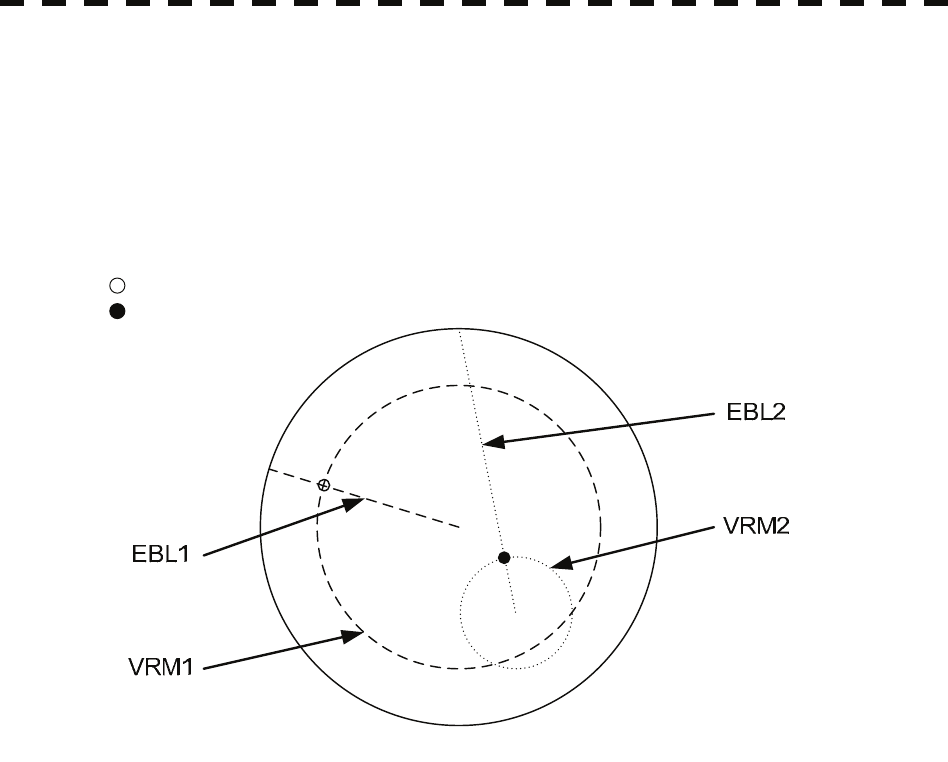
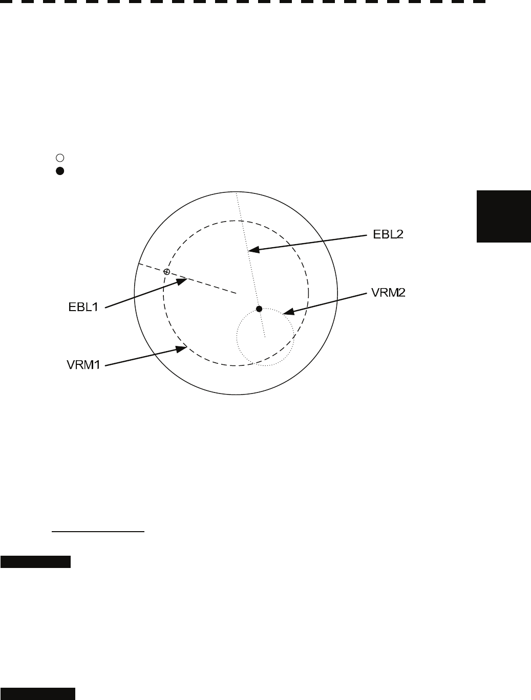
An intersection marker is displayed at the intersection point of the EBL and VRM of the same
number.
Intersection markers shown on EBL:
: EBL1, VRM1
: EBL2, VRM2
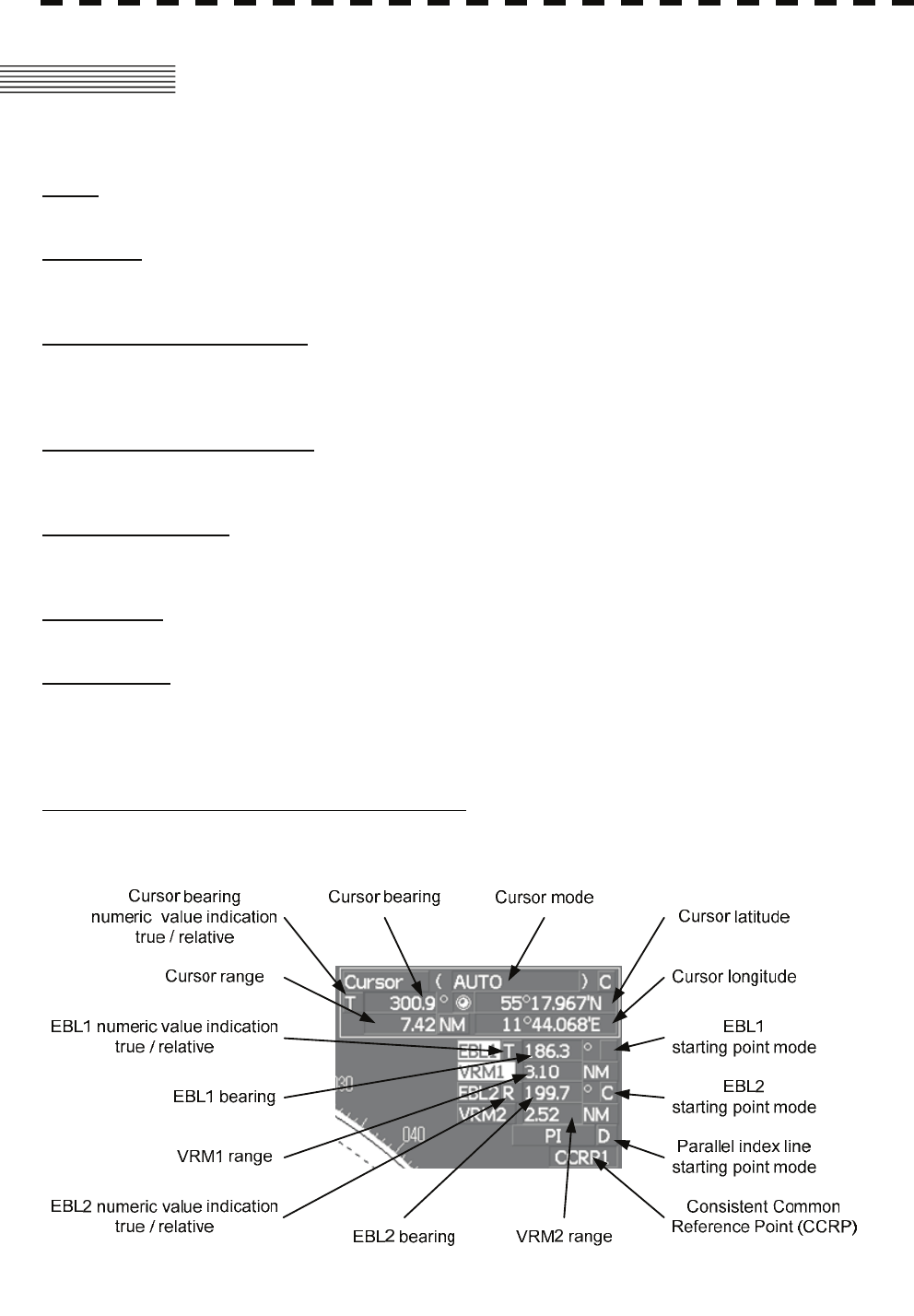
EBL Bearing Display
The bearing value of the current EBL1 or EBL2 on the PPI display is shown in the
EBL1/2 bearing (upper right of the display on page 2-3). The currently operable
EBL1 or EBL2 is highlighted in the EBL1/2 adjustment (upper right of the display ⑤
/⑦ on page 2-19).
Starting Point of EBL
The starting point of the currently operating EBL can be switched from the center of
the radar display to any offset position . The offset position of the EBL starting point
can be fixed on the radar display or at the latitude and longitude. (The setting of the
navigator is necessary for fixing the offset position at the latitude and longitude.)

4-4
4.1 Use of Navigation Tools y
yyy
4
[I] Operating EBL (EBL)
To operate EBL
Procedures 1 Press the [EBL1] or [EBL2] key.
The EBL adjustment (upper right of the display ⑤/⑦ on page 2-19) will be
highlighted, and the selected EBL becomes operable.
2 Turn the [EBL] dial.
To turn the [EBL] dial to the right, turn the EBL control clockwise, to turn the [EBL]
dial to the left, turn the EBL control counterclockwise.
Cancellation 1 Press the [EBL1] or [EBL2] key again.
The selected EBL display will disappear.
[II] Moving the Starting Point of EBL
The system provides three types of EBL starting points. Select one of them in
accordance with purpose.
:The EBL starting point is defined as the own ship's position.
C :The EBL starting point is moved and fixed on the radar display.
D :The EBL starting point is moved and fixed at the latitude and longitude.
(The navigator needs to be connected.)
To move the starting point of EBL
Procedures 1 Make EBL1 or EBL2 operable.
2 Press the [EBL] dial to set C or D for the EBL1 / EBL2 starting
point mode switching (upper right of the display ⑪/⑫ on page 2-19).
The selected EBL starting point mode is switched as shown below each time the dial is
pressed.
⇒ C ⇒ D ⇒
3 Put the cursor on the EBL starting point is to be moved, and press
the [ENT] key.
The selected EBL starting point will be determined.
4-5
To return the EBL starting point to own ship's position
Procedures 1 Make EBL1 or EBL2 operable.
2 Press the [EBL] dial to set for the EBL1 / EBL2 starting point
mode switching (upper right of the display ⑪/⑫ on page 2-19).
The selected EBL starting point will be set as the own ship's position.
[III] Setting EBL Operation Mode
To set the numeric value display mode of EBL (EBL Bearing REF)
Determine whether to display EBL in true bearing mode or relative bearing mode.
Procedures 1 Put the cursor on the EBL1/2 numeric value indication true / relative
switching (upper right of the display ⑨/⑩ on page 2-19), and press
the [ENT] key.
The selected mode is switched as shown below each time the [ENT] key is pressed.
T ⇒ R ⇒ T
T :EBL bearing is displayed in true bearing mode.
R :EBL bearing is displayed in relative bearing mode.
To set a mode for fixing EBL display (EBL Bearing Fix)
When this function is set to Angle , an EBL is fixed to the preset bearing. For example,
if a true bearing of 020° is preset, the EBL is fixed to the true bearing 020° even when the
own ship turns.
When the function is set to Screen , the EBL is fixed on the radar display. In this case,
the EBL is always fixed to the same bearing on the display when the own ship turns.
Procedures 1 Press the [RADAR MENU] key twice.
2 Open the EBL/Cursor Setting menu by performing the following menu
operation.
5. Sub Menu
9. EBL/Cursor Setting
3 Press [1] or [2] key.
To set EBL1, press the [1] key, to set EBL2, press the [2] key
Angle :EBL bearing is fixed to the preset value.
Screen :EBL bearing is fixed on the radar display.
Note: Course data is necessary for turning on this function.
4-6
4.1 Use of Navigation Tools y
yyy
4
4.1.4 Using Variable Range Marker (VRM1 / VRM2)
Variable range markers (VRM) are indispensable to the measurement of ranges. Operators must be
familiar with the operation of VRM beforehand.
The system is equipped with two VRM. The VRM can be operated separately from each other.
An intersection marker is displayed at the intersection point of the VRM and EBL of the same
number.
When the starting point of an EBL is offset, the center of the VRM is defined as the offset EBL
starting point.
Intersection markers shown on VRM:
: EBL1, VRM1
: EBL2, VRM2
VRM Operation
The range value of the current VRM1 or VRM2 on the PPI display is shown in the
VRM1/2 range (upper right of the display on page 2-3). The currently operable
VRM1 or VRM2 is highlighted in the VRM1/2 adjustment (upper right of the display
⑥/⑧ on page 2-19).
To operate VRM
Procedures 1 Press the [VRM1] or [VRM2] key.
The VRM adjustment (upper right of the display ⑥/⑧ on page 2-19) will be
highlighted, and the selected VRM becomes operable.
2 Turn the [VRM] dial.
To turn the [VRM] dial to the right, the VRM control wide, to turn the [VRM] dial to
the left, the VRM control narrow.
Cancellation 1 Press the [VRM1] or [VRM2] key again.
The selected EBL display will disappear.

4-7
4.1.5 Using Parallel Index Lines (PI Menu)
Parallel index lines can be displayed.
[I] Operating Parallel Index Lines (PI)
Procedures 1 Press the [VRM] dial.
Parallel index lines and the PI Menu will appear.
To change the bearing of parallel index lines, turn the [EBL] dial, to change the line
interval, turn the [VRM] dial.
The bearing and interval of parallel index lines are displayed in the PI Menu.
2 Press the [VRM] dial again.
The parallel index lines will be fixed.
Note: Parallel index lines are operable only while the PI Menu is displayed. When the menu is
closed, the parallel index line display remains, but the settings of the bearing and interval
cannot be adjusted any more. To adjust the bearing and interval after closing the menu,
press the [VRM] dial twice to open the PI Menu.
Cancellation 1 Press the [VRM] dial again.
The parallel index line display will disappear.
4-8
4.1 Use of Navigation Tools y
yyy
4
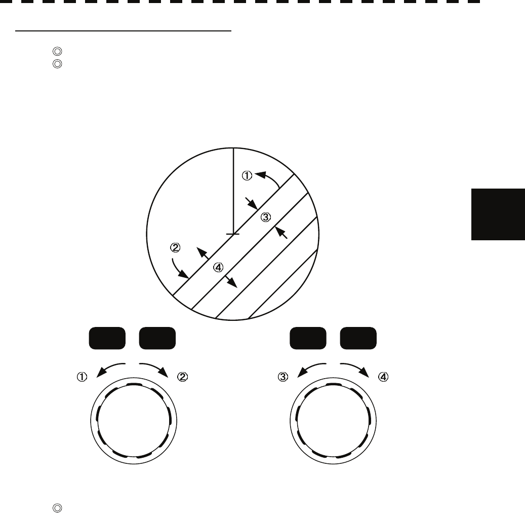
[II] Operation of Parallel Index Lines
Parallel index lines rotate in the same direction as you turn the [EBL] dial. ( ① , ② )
The intervals of parallel index lines narrow when you turn the [VRM] dial counterclockwise
( ③ ), and widen when you turn the [VRM] dial clockwise ( ④ ).
HL
EBL1 EBL2 VRM1 VRM2
When the [VRM] dial is pressed, the PI Menu closes and the parallel index lines are fixed.
During the operation of parallel index lines, pressing the [EBL1] or [EBL2] key disables operation
for rotation directions. Pressing the [VRM1] or [VRM2] key disables operation for parallel index
line intervals.
4-9
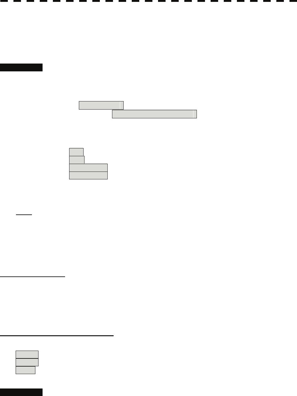
[III] Settings in PI Menu
The operation of parallel index lines can be set in the PI Menu.
Procedures 1 Open the PI Menu by performing the following menu operation.
Tool
1. PI Menu
[1] Display for All Lines
Sets the parallel index line display to on or off.
On :Parallel index lines are displayed.
Off :Parallel index lines are not displayed.
[2] Operation Mode
Sets an operation mode for parallel index lines.
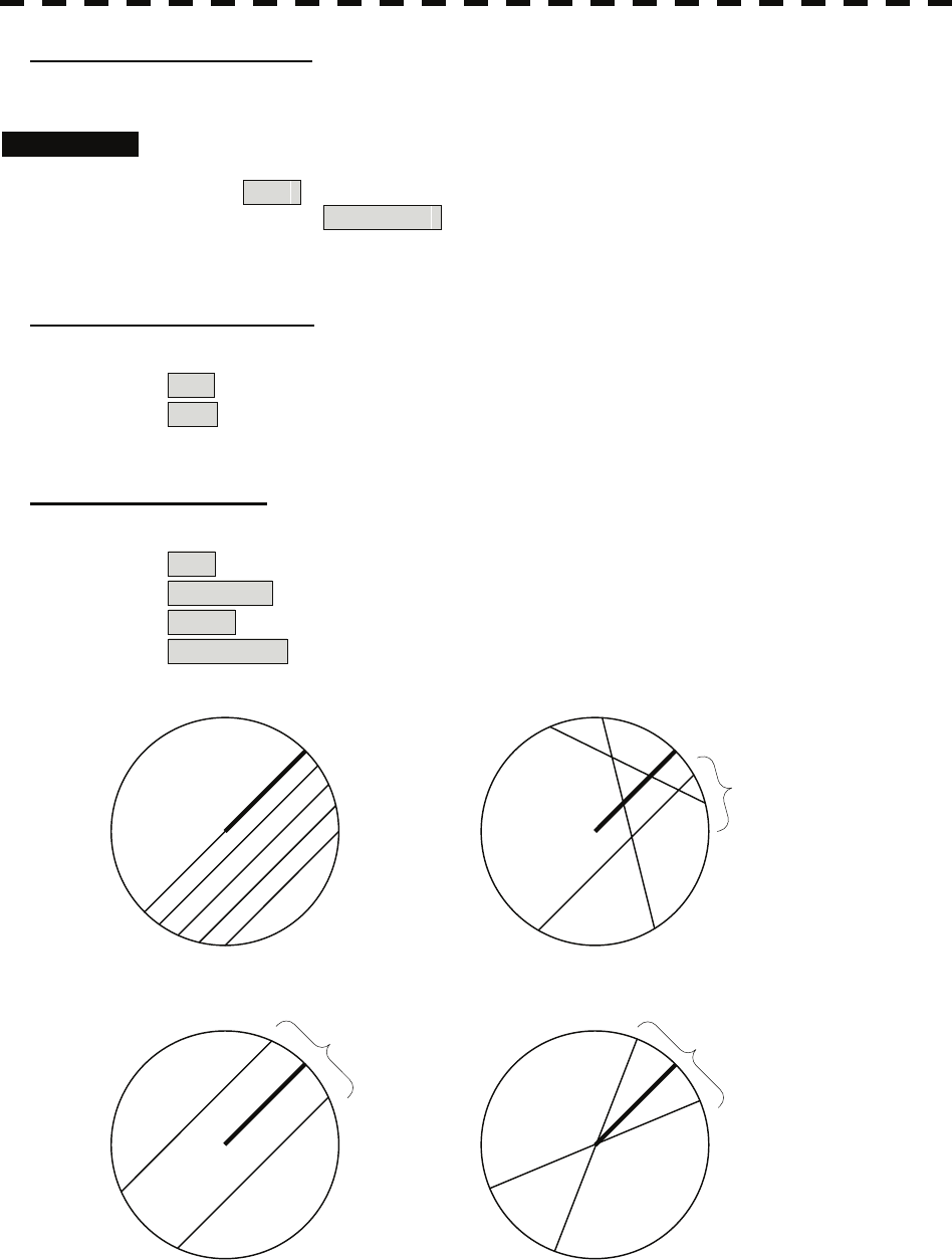
All :All the parallel lines are operated at the same time.
Individual :The bearing of each line is operated individually.
Track :Equally spaced lateral lines are displayed on both sides.
Equiangular :Two lines intersecting at the center of a circle are displayed.
All Individual
Track Equiangular
PI
PI PI
PI

4-10
4.1 Use of Navigation Tools y
yyy
4
Operation if Individual is selected
A line perpendicular to the own ship and the intersection marker "----○" are displayed on an
operable line.
Turning the [EBL] dial changes the direction.
Pressing the [VRM] dial changes the range, end point 1, or end point 2 to be operated.
An operable point is displayed with " " and can be operated by turning the [VRM] dial.
If Sequential is selected for [3] Control, the parallel index lines of the next number can
be displayed by pressing the [EBL] dial.
To close the menu, press [0] key.
Operation if Equiangular is selected
Select a group of lines to be operated according to the setting of [3] Control.
Pressing the [EBL] dial switches between the direction change mode and elevation-angle
change mode. Turning the [EBL] dial changes the direction or elevation angle.
[3] Control
Determines whether to operate all the lines at the same time. The setting items are determined by
the setting of [2] Operation Mode.
If All is selected
The setting cannot be changed.
All : All the lines are operated at the same time.
If Individual is selected
Determine whether to set consecutive lines or individual lines.
Sequential : Lines are operated sequentially.
Index Line1 to Line8 : A specified line is operated.
If Track or Equiangular is selected
Select a group of lines to be operated.
Group1 to Group4 : A specified group is operated.
[4] Floating
Moves the center point of parallel index lines.
Off : The starting point of parallel index lines is defined as the own ship's
position.
Screen Fix : The center of parallel index lines is moved and fixed on the radar
display.
L/L Fix : The center of parallel index lines is moved and fixed at the latitude
and :longitude. (The navigator needs to be connected.)
[5] Heading Link
Determines whether to operate parallel index lines following the heading bearing.
On : Parallel index lines are operated following the heading bearing.
Off : Parallel index lines are not operated following the heading bearing.
4-11
[6] Next
Moves to the next page.
[1] Range Scale Link
Determines the operation of parallel index line intervals when the range is changed.
On : The intervals are fixed with the actual range (nm).
The appearance of parallel index line intervals changes when the range
is changed.
Off : The intervals are fixed with the display range.
The parallel index line intervals (nm) change when the range is
changed.
[2] Reference Bearing
Sets a reference bearing for the numeric data display of parallel index lines. The setting items are
determined by the setting of [2] Operation Mode.
If All is selected
True : Displayed with true bearing (with North as reference).
HL : Displayed with the heading line as reference.
If Individual is selected
True : Displayed with true bearing
(with North as reference).
HL : Displayed with the heading line as reference.
Index Line1 to Line8 : Displayed with a specified line as reference.
If Track is selected
True : Displayed with true bearing
(with North as reference).
HL : Displayed with the heading line as reference.
Index Line1 to Line8 : Displayed with a specified line as reference.
Line1 , Line3 , Line5 , and Line7
correspond to Group1 , Group2 , Group3 , and
Group4 , respectively.
If Equiangular is selected
The setting cannot be changed.
[3] Operation Area
If All is selected for [2] Operation Mode, this function sets an area for displaying parallel index
lines. One Side : Parallel index lines are displayed only on one side.
Both Sides : Parallel index lines are displayed on both sides.
4-12
4.1 Use of Navigation Tools y
yyy
4
[4] Display for Individual Line
Determines whether to turn on / off the parallel index line display of a selected number.
On : The line of the selected number is displayed.
Off : The line of the selected number is not displayed.
If All is selected for [2] Operation Mode, the line near the own ship is line1.
If Track or Equiangular is selected for [2] Operation Mode, Line1 , Line3 ,
Line5 , and Line7 correspond to Group1 , Group2 , Group3 , and Group4 ,
respectively.
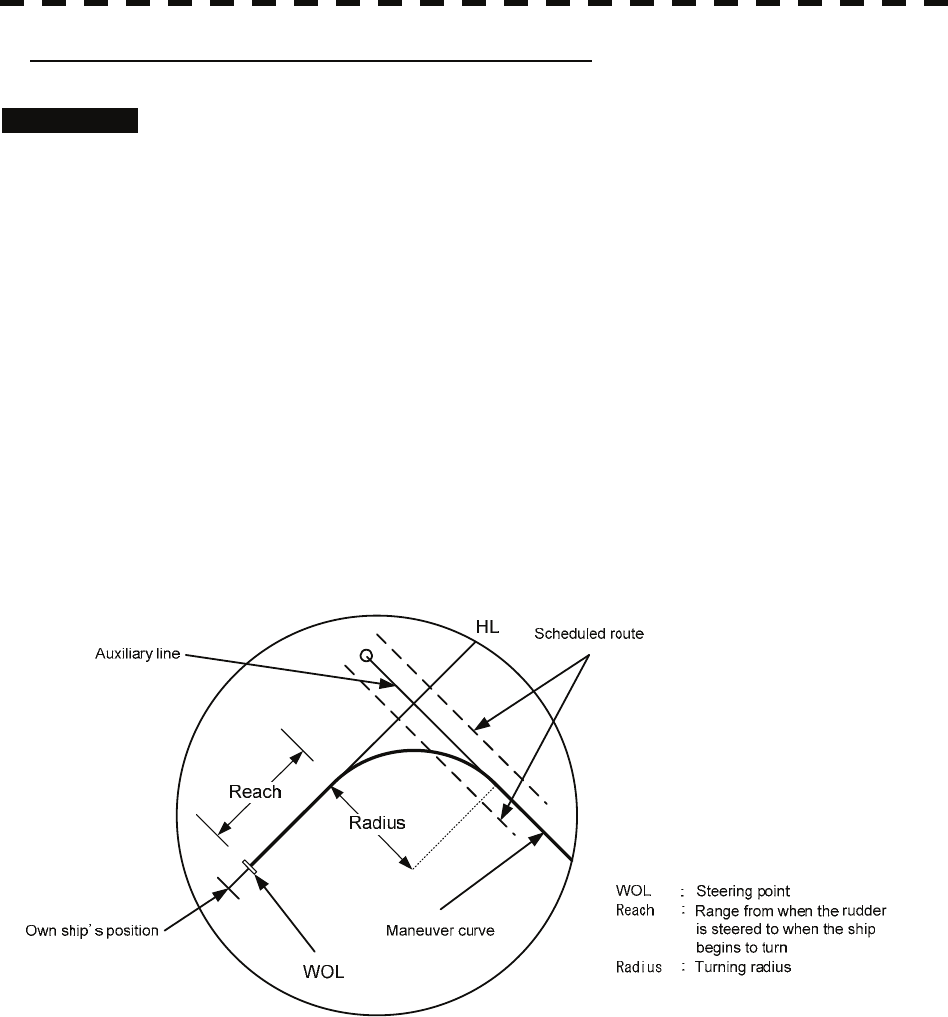
4.1.6 Operating EBL Maneuver Function (EBL Maneuver Setting)
[I] Initial Setting (EBL Maneuver Setting)
Procedures 1 Open the EBL Maneuver Setting menu by performing the following
menu operation.
Tool
3. EBL Maneuver Setting
2 Set the following parameters.
Reach : Set the range from when the rudder is steered to when the ship
beings to turn.
Turn Mode : Select a turn mode.
Radius :Turning radius (nm)
Rate :Rate of turn (deg/min)
Turn Set : Select the setting for turning.
If Radius is selected : Turning radius (nm)
If Rate is selected : Rate of turn (deg/min)
For inputs to the numeric value input menu, refer to Section 3.3.4.
Note: A wrong initial setting affects the maneuver curve function explained below.
4-13
[II] Creation of Maneuver Curve (EBL Maneuver)
Procedures 1 Press the [1] key while the EBL Maneuver Setting menu is open.
The EBL maneuver function will be set to on or off.
A auxiliary line for maneuver curve creation, a maneuver curve, and a WOL will
appear on the radar display.
2 Put the cursor on the starting point of the auxiliary line, and set the
bearing of the auxiliary line by operating the [EBL] dial.
The bearing of the auxiliary line is the final bearing in which the own ship is to move.
The WOL position varies depending on the bearing of the auxiliary line.
If the WOL is behind the own ship's position, the line color of WOL will change.
3 Press the [ENT] key.
The setting will be determined. However, if the WOL is behind the own ship's
position at this point, pressing of the [ENT] key is rejected, and the setting is not
determined.
4-14
4.1 Use of Navigation Tools y
yyy
4
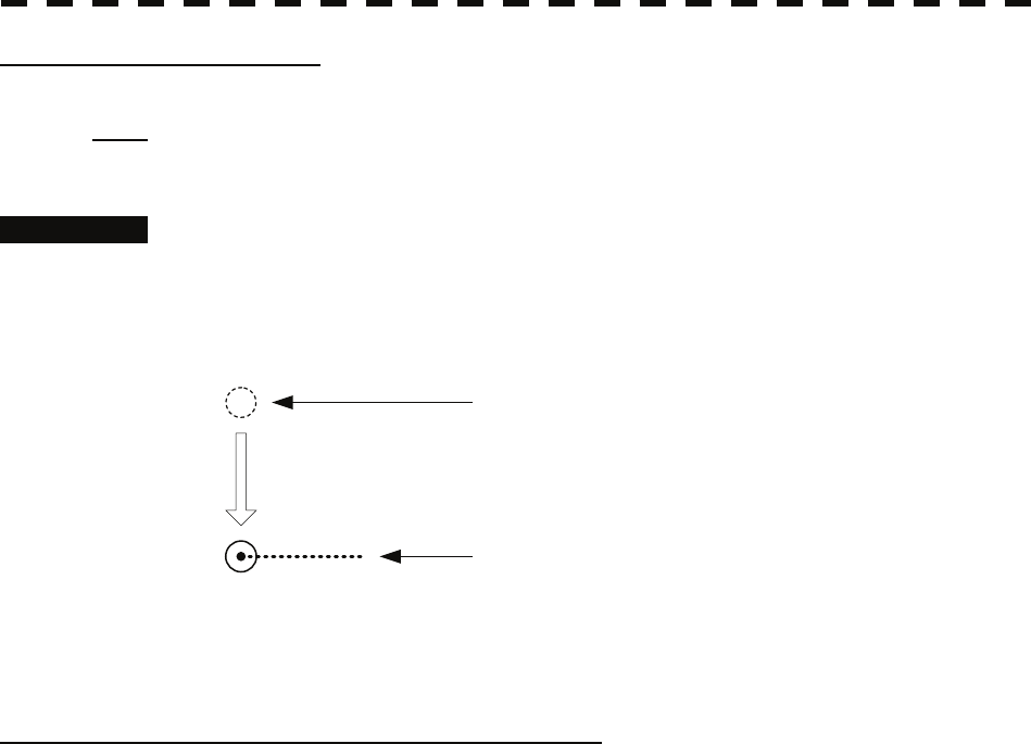
4.1.7 Using MOB [MOB]
The marker (anchor symbol) function displays a dotted line from the marker input position to the own
ship's position, and indicates the range, bearing, and required time from the own ship's position to the
marker. (The navigator needs to be connected.)
For example, the function can be used for following purposes:
To confirm the drifting distance from where the ship was anchored.
To record a position of man overboard.
Procedures 1 Press the [MOB] key.
A marker will be displayed at the own ship's position on the radar display at the
moment when the [MOB] key is pressed. The own ship and the marker are
connected with a dotted line.
Even when the own ship moves, the marker is fixed at the latitude and longitude.
Thus, if a marker is put to an important position, the ship can return to the position
regarding the marker as a target.
Cancellation 1 Press the [MOB] key for 2 seconds.
The marker will disappear.
4.1.8 Operating EBL, VRM, and PI with Cursor
When the cursor mode is set to AUTO (upper right of the display on page 2-3), EBL, VRM, and
PI can be operated simply by using the trackball and the [ENT] key.
[I] Operating Electronic Bearing Line (EBL)
Procedures 1 Put the cursor on EBL1 or EBL2, and press the [ENT] key.
When the cursor is moved to it, EBL1 or EBL2 is shown at the upper right of
the cursor. The EBL becomes operable when the [ENT] key is pressed.
2 Move the cursor to the bearing to be set.
The EBL will move as the cursor moves.
3 Press the [ENT] key.
The EBL will be fixed.

4-15
[II] Operating Variable Range Marker (VRM)
Procedures 1 Put the cursor on VRM1 or VRM2, and press the [ENT] key.
When the cursor is moved to it, VRM1 or VRM2 is shown at the upper right
of the cursor. The VRM becomes operable when the [ENT] key is pressed.
2 Move the cursor to the range to be set.
The VRM will move as the cursor moves.
3 Press the [ENT] key.
The VRM will be fixed.
[III] Operating EBL and VRM Concurrently (EBL and VRM)
Procedures 1 Put the cursor on the intersection marker ( ○ or ● ), and press
the [ENT] key.
When the cursor is moved to it, EBL1 VRM1 or EBL2 VRM2 is shown at the
upper right of the cursor. The EBL and VRM become operable when the [ENT] key
is pressed.
2 Move the cursor to the bearing / range to be set.
The EBL and VRM will move as the cursor moves.
3 Press the [ENT] key.
The EBL and VRM will be fixed.
[IV] Operating Parallel Index Lines (PI)
To change the direction of parallel index lines
Procedures 1 Put the cursor on near the center of line, and press the [ENT] key.
When the cursor is moved there, it will turn into " " and PI will be displayed at
the upper right of the cursor. The parallel index lines become operable when the
[ENT] key is pressed.
2 Move the cursor to the direction to be set.
The parallel index lines will change the direction as the cursor moves.
3 Press the [ENT] key.
The parallel index lines will be fixed.

4-16
4.1 Use of Navigation Tools y
yyy
4
To change parallel index line intervals
Procedures 1 Put the cursor on near the end of line, and press the [ENT] key.
When the cursor is moved there, it will turn into " " and PI will be displayed at
the upper right of the cursor. The parallel index lines become operable when the
[ENT] key is pressed.
2 Move the cursor to the interval to be set.
The parallel index lines interval will change as the cursor moves.
If Individual is selected for Operation Mode, the parallel index lines move.
3 Press the [ENT] key.
The parallel index lines will be fixed.
To change the end points of parallel index lines
If Individual is selected for Operation Mode, the length of parallel index lines can be
changed.
Procedures 1 Put the cursor on the end point of parallel index lines, and press the
[ENT] key.
When the cursor is moved there, it will turn into " " and PI will be displayed at
the upper right of the cursor. The parallel index lines become operable when the
[ENT] key is pressed.
2 Move the cursor to the position to be set.
The position of the end point will change as the cursor moves.
3 Press the [ENT] key.
The parallel index lines will be fixed.
4-17
4.2 MEASUREMENT OF RANGE AND
BEARING
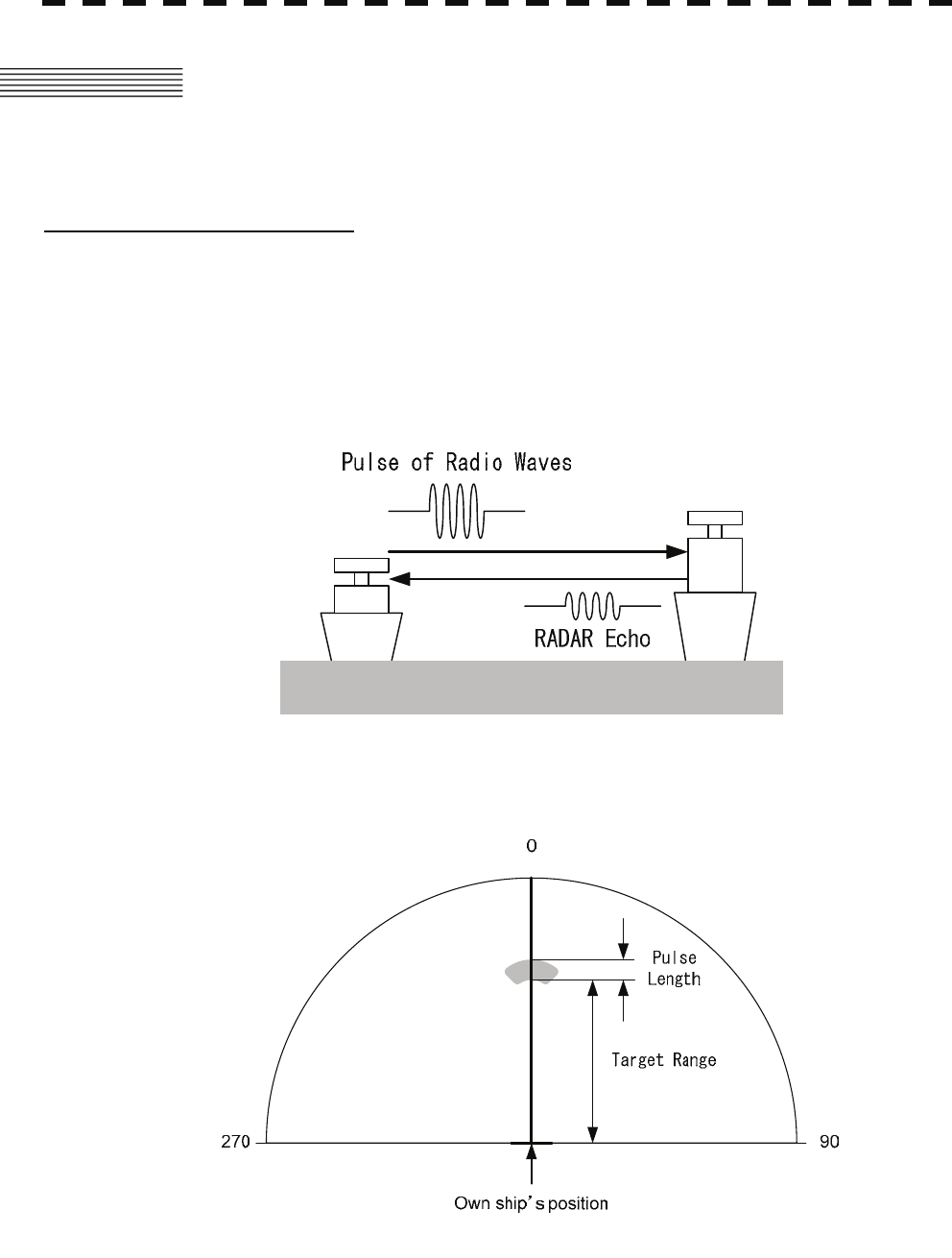
Target position on the RADAR screen
RADAR antenna transmits pulses of radio waves. The object returns the wave (radar echo) to the
antenna.
So on the RADAR screen the leading edge of echo is the actual target position.
The length of echo is dependent on the transmitted pulse length.
Point the cursor to the leading edge of echo to measure the target range or to make a mark on the
target.
Fig. 4.1 Transmitting-Receiving of RADAR
Fig. 4.2 Relation of echo, target range and pulse length
4-18
4.2 Measurement of Range and Bearing y
yyy
4
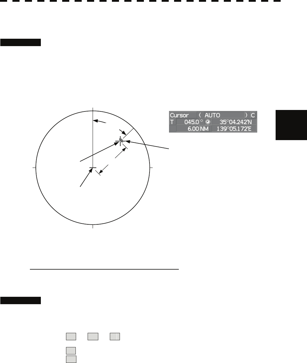
4.2.1 Measurement with Cursor Position (Cursor)
Procedures 1 Make sure of the target echoes on the radar display.
2 Move the cursor to the target.
The bearing and range of the target will be shown in the Cursor bearing / range (upper
right of the display on page 2-3). The range is a distance from the own ship's
position.
Target
Cursor
45.0°
180
0
90270 6.00NM
Bearing and range from the
own ship’s position to target in this figure:
True bearing 45.0 °
Range 6.00 NM
Own ship’s position
To set a cursor bearing numeric value mode
Determine whether to display a cursor bearing in true or relative bearing mode.
Procedures 1 Put the cursor on the Cursor bearing numeric value indication true /
relative switching (upper right of the display ④ on page 2-19), and
press the [ENT] key.
The selected mode is switched as shown below each time the [ENT] key is pressed.
T ⇒ R ⇒ T
T :Cursor bearing is displayed in true bearing mode.
R :Cursor bearing is displayed in relative bearing mode.
4-19
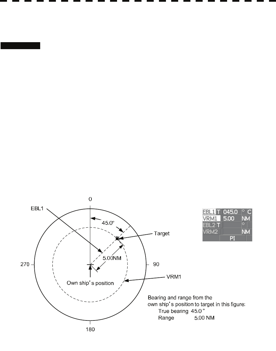
4.2.2 Measurement with Electronic Bearing Line and Variable
Range Marker [EBL] [VRM]
Procedures 1 Press the [EBL1] key.
The display in the EBL1 adjustment (upper right of the display ⑤ on page 2-19) will
be highlighted, and EBL1 will be shown with a dotted line on the PPI display.
2 Move the EBL1 to the target by turning the [EBL] dial.
The EBL1 bearing will be shown in the EBL1 bearing (upper right of the display on
page 2-3).
The EBL1 bearing is the bearing of the target.
3 Press the [VRM1] key.
The display in the VRM1 adjustment (upper right of the display ⑥ on page 2-19)
will be highlighted, and VRM1 will be shown with a dotted line on the PPI display.
4 Move the VRM1 to the target by turning the [VRM] dial.
The range of VRM1 from the own ship's position will be shown in the VRM1 range
(upper right of the display on page 2-3).
4-20
4.2 Measurement of Range and Bearing y
yyy
4
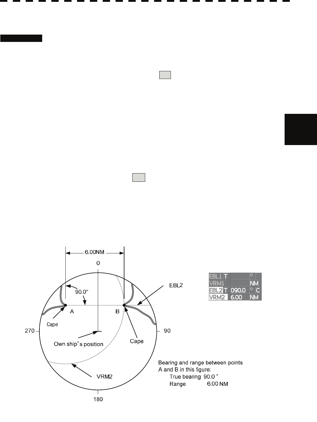
4.2.3 Measurement with Two Arbitrary Points
Procedures 1 Press the [EBL2] key.
The display in the EBL2 adjustment (upper right of the display ⑦ on page 2-19) will
be highlighted, and EBL2 will be shown on the PPI display.
2 Press the [EBL] dial to select C for the EBL2 starting point mode
switching (upper right of the display ⑫ on page 2-19).
3 Put the cursor on the point A of the two points between which
measurement is made, and press the [ENT] key.
Refer to the figure below.
4 Move the EBL2 to the other point B by turning the [EBL] dial.
Refer to the figure below.
5 Press the [VRM2] key.
When VRM2 is selected, ● (intersection marker) will appear on the dotted line of
EBL2.
6 Move the intersection marker on the dotted line to point B by turning
the [VRM] dial.
The range and bearing between the two points will be shown in the VRM2 range and
EBL2 bearing (upper right of display on page 2-3).
Similarly, EBL1 can also be used for measuring the bearing and range between two points. In this
case, perform the above procedure reading EBL2 as EBL1 and VRM2 as VRM1.

SECTION 5
OPERATION OF TARGET TRACKING
AND AIS
USAGE OF TARGET TRACKING FUNCTION ............................................5-1
5.1 PREPARATION....................................................................................5-2
5.2 TARGET TRACKING OPERATION...................................................5-16
5.3 AIS OPERATION................................................................................5-31
5.4 DECISION OF TARGETS AS IDENTICAL (ASSOCIATION) ............5-42
5.5 ALARM DISPLAY ..............................................................................5-44
5.6 TRACK FUNCTION ...........................................................................5-48
5.7 TRIAL MANEUVERING (TRIAL MANEUVER)..................................5-58
5.8 EPA OPERATION...............................................................................5-62

5-1
z There are the following limitations on use of the target
acquisition and target tracking functions.
[I] Resolution between adjacent targets and swapping
during automatic target tracking
Depending on the particular distance and echo size,
resolution between adjacent targets during automatic target
tracking usually ranges somewhere between 0.03 to 0.05 NM.
If multiple targets approach each other, resolution will
become about 0.05 NM and this may cause the system to
regard them as one target and thus to swap them or lose part
of them. Such swapping or less of targets may also occur if
the picture of the target being tracked is affected by rain/snow
clutter returns or sea clutter returns or moves very close to
land.
[II] Intensity of echoes and the target tracking function
The intensity of echoes and the tracking function have a
correlationship, and thus the target will be lost if no echoes
are detected during six scans in succession. If a lost target
exists, therefore, radar gain must be increased to support
detection of the target. If, however, radar gain is increased
too significantly, sea clutter returns or other noise may be
erroneously detected and tracked as a target, and resultingly,
a false alarm may be issued.
[III] Adverse effects of error sources on automatic
tracking
To execute accurate tracking, it becomes necessary first to
appropriately adjust the [GAIN], [SEA] and [RAIN] dials of the
radar so that the target to be acquired and tracked id clearly
displayed on the radar display. Inappropriate settings of
these adjustments reduce the reliability / accuracy of
automatic tracking.
USAGE OF TARGET TRACKING FUNCTION
Attention
5-2
5.1 Preparation yy
yyy
5
5.1 PREPARATION
This section explains the features of the target tracking and AIS functions, and the initial setting for using each
function.
Target Tracking Function (Option)
The target tracking function calculates the course and speed of a target by automatically tracking the
target's move.
The target tracking function enables the automatic acquisition of targets by using the automatic
acquisition zone function.
The target tracking function also enables the simulation of the ship maneuvering method to avoid
collisions by using the trial maneuver function. (NCA-877WA)
If the mode is ground stabilization, SOG/COG used for own ship's information in target tracking. If the
mode is sea stabilization, SPD (speed through the water) / HDG (heading) used for own ship's
information in target tracking.
Normal edition
NCA-877A High performance edition
NCA-877WA
Maximum number of targets that
can be tracked 30 100
Trial maneuver function Not provided Provided
Note: ARPA Process Unit (NCA-877WA) or ATA Process Unit (NCA-877A) must be fitted on ships
compliant to IMO.
AIS (Automatic Identification System) function (Option)
The AIS function shows the target’s information on the radar display, using other ship's information sent
out from the AIS unit.
Note: AIS Process Unit must be fitted on ships compliant to IMO.
5-3
5.1.1 Collision Avoidance
Problems of Collision Avoidance in Navigation
Marine collision avoidance is one of the problems that have been recognized from of old. Now, it will be
described briefly who the collision avoidance is positioned among the navigational aid problems.
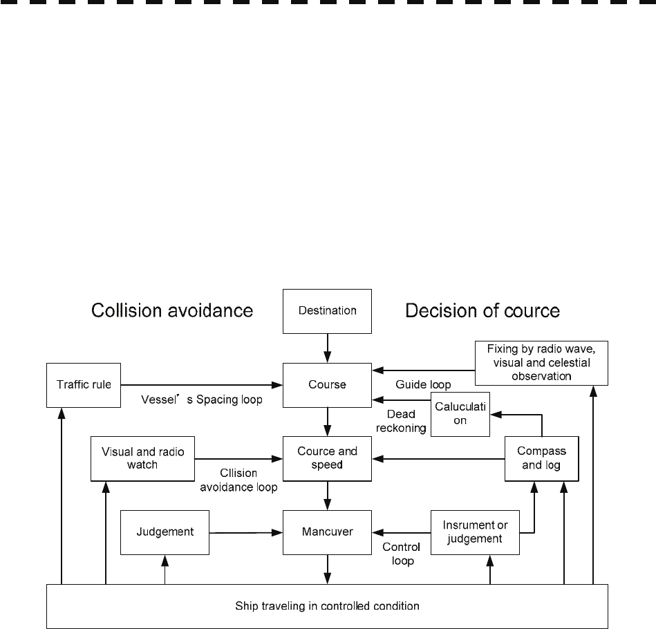
The navigation pattern of all mobile craft constitutes a system with some closed loops regardless of the media
through which the mobile craft travels, whether air, water, the boundary between air and water, or space. This
pattern consists of two closed loops in principle, one of which is a collision with another mobile craft and the
other is a loop of finding a right and safe way to reach a predeterminate destination. Fig. 5-1 shows the
conceptual diagram of navigation pattern by MR. E.W. Anderson. The closed loop of collision avoidance is
shown on the left side and the closed loop of finding a right course on the right side.
Fig. 5-1 Navigation Pattern
Marine Accidents and Collisions
Among marine accidents, collision accidents have been highlighted as the tonnages and speeds of ships become
higher along with the increase in traffic at sea. If a tanker carrying dangerous articles such as crude oil
collides with any other vessel, then not only the vessels involved with the accident but other vessels in the
vicinity, port facilities, inhabitants in the coastal area as well as marine resources may also suffer immeasurable
damages and troubles. Collision accidents have a high percentage of the marine accidents that have occurred
in recent years. To cope with these problems, any effective measures are needed and some equipment to
achieve collision avoidance requirements have been developed at rapid strides.
5-4
5.1 Preparation yy
yyy
5
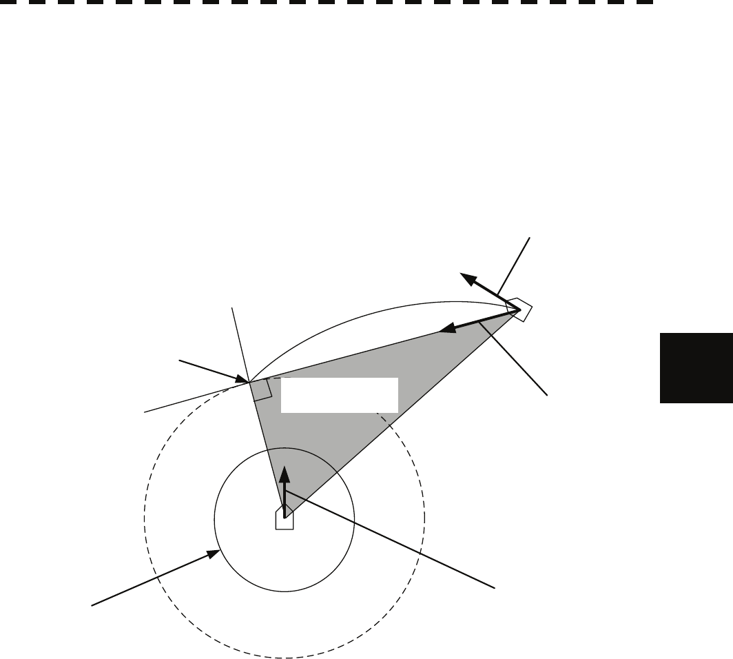
Basic Concept of Collision Avoidance
There are two aspects in collision avoidance: collision prediction and avoidance. Collision prediction is to
predict that two or more vessels will happen to occupy the same point at the same time, while collision
avoidance is to maneuver vessels not to occupy the same point at the same time.
In practical operation of vessels, a spot of collision has to be deemed to be a single point but a closed zone.
This closed zone is conceptually defined as a CPA (Closest Point of Approach). In collision prediction, the
time to be taken until a ship reaches the CPA is defined as a TCPA (Time to CPA).
Fig. 5-2 shows a diagram caked “Collision Triangle”.
CPA
Target Vessel True Vector
Own Ship True Vector
Own Ship
TCPA(Time to CPA)
Target vessel
CPA ring
Relative Vector
Collision Triangle
Fig. 5-2 Collision Triangle
5-5
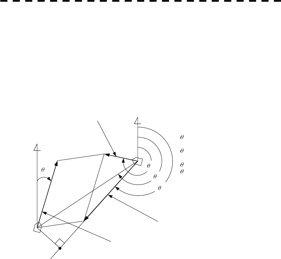
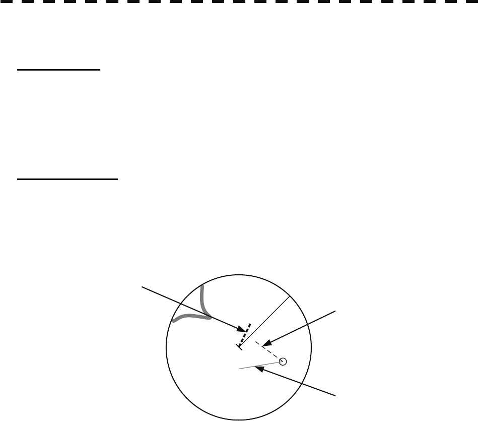
Relative Vector and True Vector
From two points of view, collision prediction and avoidance, it is necessary to obtain the relative vector of other
ship for prediction and the true vector of other ship for collision avoidance in order to grasp other ship’s aspect.
The relationship between the relative vector and true vector is shown in Fig. 5-3.
Both rough CPA and TCPA can be obtained easily from the relative speed vector of other ship. This method
has an advantage that the risks of collision with all other ships within the radar range can be seen at a glance.
On the other hand, the course and speed of other ship can easily be obtained from its true speed vector, enabling
other ship’s aspect to be seen at a glance. Thus, the aspects of other ships (transverse, outsail, parallel run,
reverse run, etc...) as described in the act of prevention of collision at sea can be readily grasped. If there is a
risk of collision with other ship, the operator can determine which rule to be applied and how to operate own
ship.
N
T
R
A
O
Vo
VR
VT
VO: Own ship's speed
O: Own ship's course
VT: Other ship's true speed
T: Target ship's true course
VR: Target ship's relative speed
R: Target ship's relative course
A: Aspect
Relative vector
Target ship true vector
N
CPA
Own ship true vector
Fig. 5-3 Relative Vector and True vector
Radar and Collision Avoidance
Radar is still playing an important roll for collision prevention and positioning. A plotter is used to further
enhance the radar functionality. The plotter is capable of plotting other positions of other ships in 3 to 6
minute intervals to monitor their movement. The plots of other ships represent their tracks relative to own
ship, and it is shown whether there is a risk of collision, namely CPA and TCPA can be obtained. This method
using a plotter is fairly effective, but the number of target ship, which is manually plotted, is limited and it takes
several minutes to measure those.
5-6
5.1 Preparation yy
yyy
5
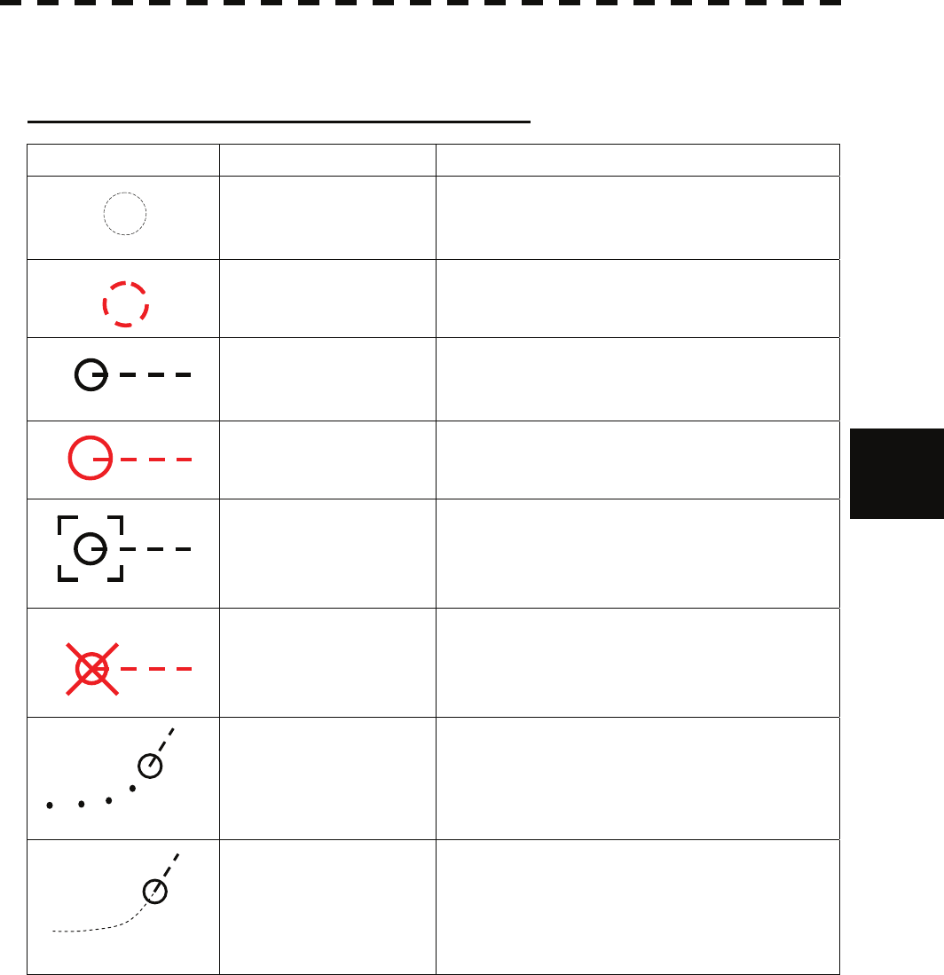
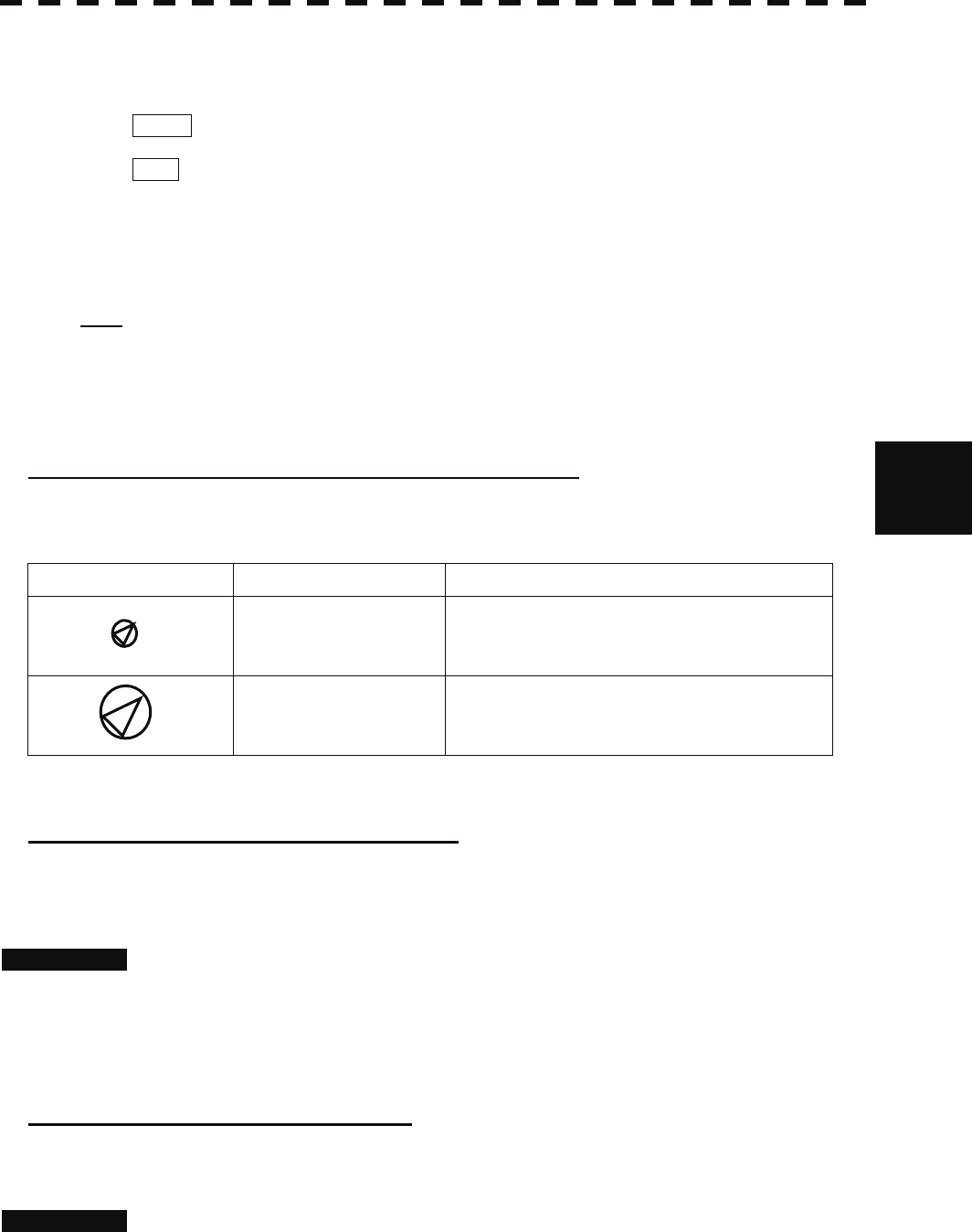
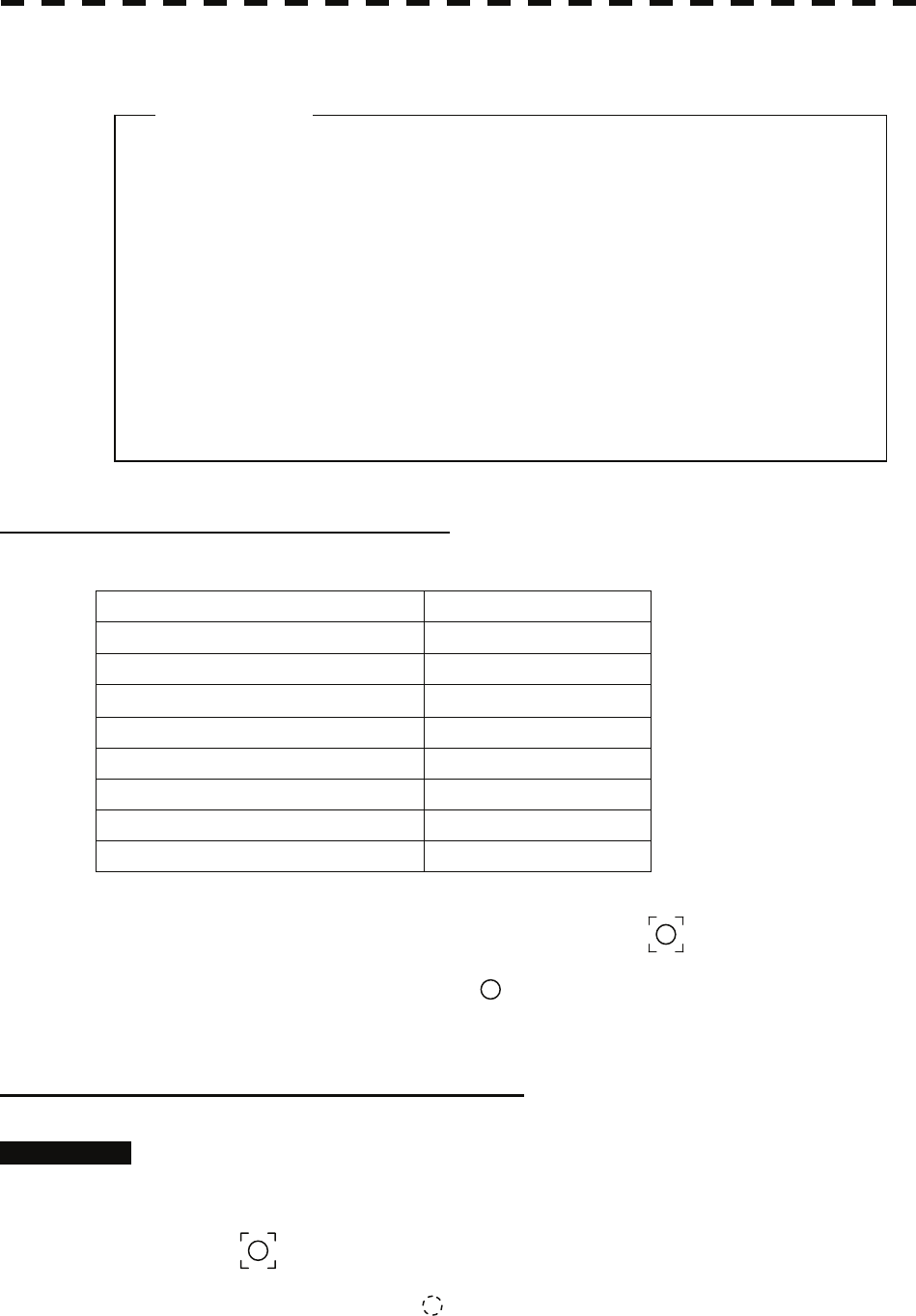
5.1.2 Definitions of Symbols
Types and Definitions of Target Tracking Symbols
Vector/Symbol Definition Remarks
Initial acquisition target This symbol is displayed until the vector is displayed
after target acquisition.
Target acquired in
automatic acquisition zone
The alarm sounds.
The alarm message (New Target) turns red and blinks.
The symbol is red colored.
Tracked target
Dangerous target
The alarm sounds.
The alarm message (CPA/TCPA) turns red and blinks.
The symbol turns red and enlarges.
Numeric displayed target When the numeric data is displayed, the target symbol
is enclosed in a square.
Lost target
The alarm sounds.
The alarm message (Lost) turns red and blinks.
The symbol turns red, and indicates with X mark.
Past position The past positions of an AIS target are displayed as
well as the target tracking symbol.
Target track The track of another ship as an AIS target is displayed
as well as the target tracking symbol.
12
12
12
12
12
12
12
12
5-7
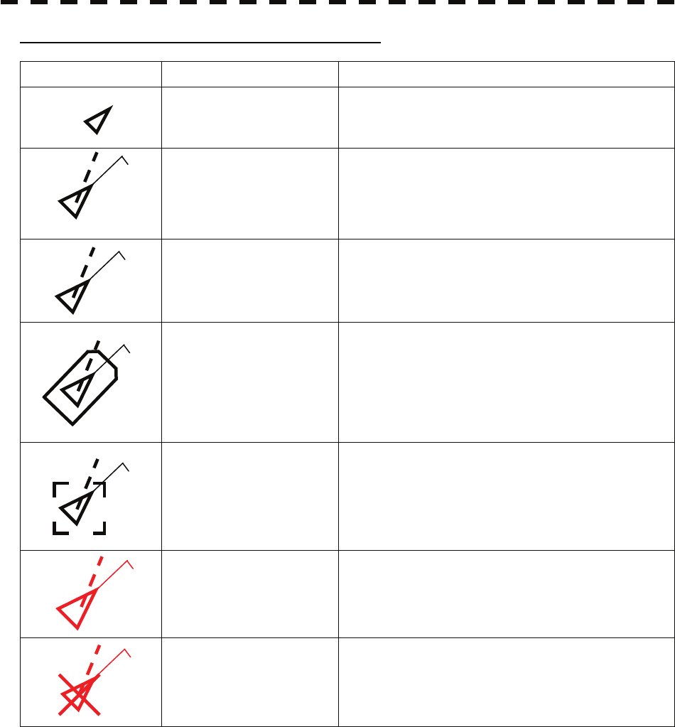
Types and Definitions of AIS Target Symbols
Vector/Symbol Definition Remarks
Sleeping target This symbol is displayed when received data is valid.
The direction of the triangle’s vertex indicates the
target’s bow or course.
Activated target
The heading direction is displayed with a solid line, and
the course vector is displayed with a dotted line. The
line perpendicular to the heading direction indicates the
direction to which the course is to be changed. This
line may not be displayed.
Target acquired in automatic
acquisition zone The alarm sounds.
The alarm message (New Target) turns red and blinks.
Outline display The outlines of ships are displayed scaled down.
Numeric displayed target When the numeric data is displayed, the target symbol
is enclosed in a square.
Dangerous target
The alarm sounds.
The alarm message (CPA/TCPA) turns red and blinks.
The symbol turns red and enlarges.
Lost target
The alarm sounds.
The alarm message (Lost) turns red and blinks.
The symbol turns red, and indicates with X mark.
Up to 300 targets can be displayed in total of activated and sleeping AIS targets. Up to 100 activated AIS
targets can be included in the total.
If there are more AIS targets than the allowable maximum, they are displayed in the following priority order:
1. Numeric displayed target
2. Target of which CPA / TCPA is lower than the set value
(Target as a dangerous ship for which an alarm has occurred)
3. Target in automatic activation zone
4. Activated AIS target
5. Target inside AIS filter
6. Target outside AIS filter
If the number of targets at the same priority level exceeds the allowable maximum, they are displayed in the
following priority order:
1. Association target
2. Activated AIS target
3. Sleeping AIS target
AIS12
AIS12
AIS12
AIS12
AIS12
AIS12
5-8
5.1 Preparation yy
yyy
5
The vector of an AIS target is to be displayed with a vector over ground or over water, depending on the speed
sensor setting and current offset setting. The type of the currently displayed vector can be confirmed by
viewing the setting of the stable mode.
When GND is displayed for the stability mode (upper left of the display on page 2-2):
Vector over ground
When Sea is displayed for the stability mode (upper left of the display on page 2-2):
Vector over water
When the vector of an AIS target is displayed with a vector over water, the system has converted the AIS
target's vector over ground to the vector over water according to the data received from the AIS and the own
ship's information.
Note: When the AIS target's symbol is activated but the vector is not displayed, the following are
probable causes of the trouble:
COG/SOG is not yet input from the GPS.
The selected speed sensor is malfunctioning.
Types and Definitions of Association Target Symbols
When a tracked target and an AIS target are decided as identical, it is displayed with either of the following
symbols:
Vector/Symbol Definition Remarks
Priority for tracked target
Association target
Priority for AIS target
Association target
Setting of Tracked Target Symbol Display
This function switches the tracking target symbol display between on and off.
Even if the tracking target symbol display is turned off, the data is retained.
Procedures 1 Move the cursor onto the tracking target symbol display On / Off (TT / AIS
information ⑨ on page 2-23), and press the [ENT] key.
The tracking target symbol display will be set to on or off.
Setting of AIS Target Symbol Display
This function switches the AIS target symbol display between on and off.
Procedures 1 Move the cursor onto the AIS target symbol display On / Off (TT/AIS
information ⑩ on page 2-23), and press the [ENT] key.
The AIS target symbol display will be set to on or off.
AIS12
12
5-9
5.1.3 Radar Display
Vector Display
A vector to represent a target’s predicted position can be presented in the True vector or Relative vector mode.
In each mode, a vector length can be freely changed for a time interval of 1 to 60 minutes.
To switch between the true vector mode and relative vector mode, press the [VECT R/T] key.
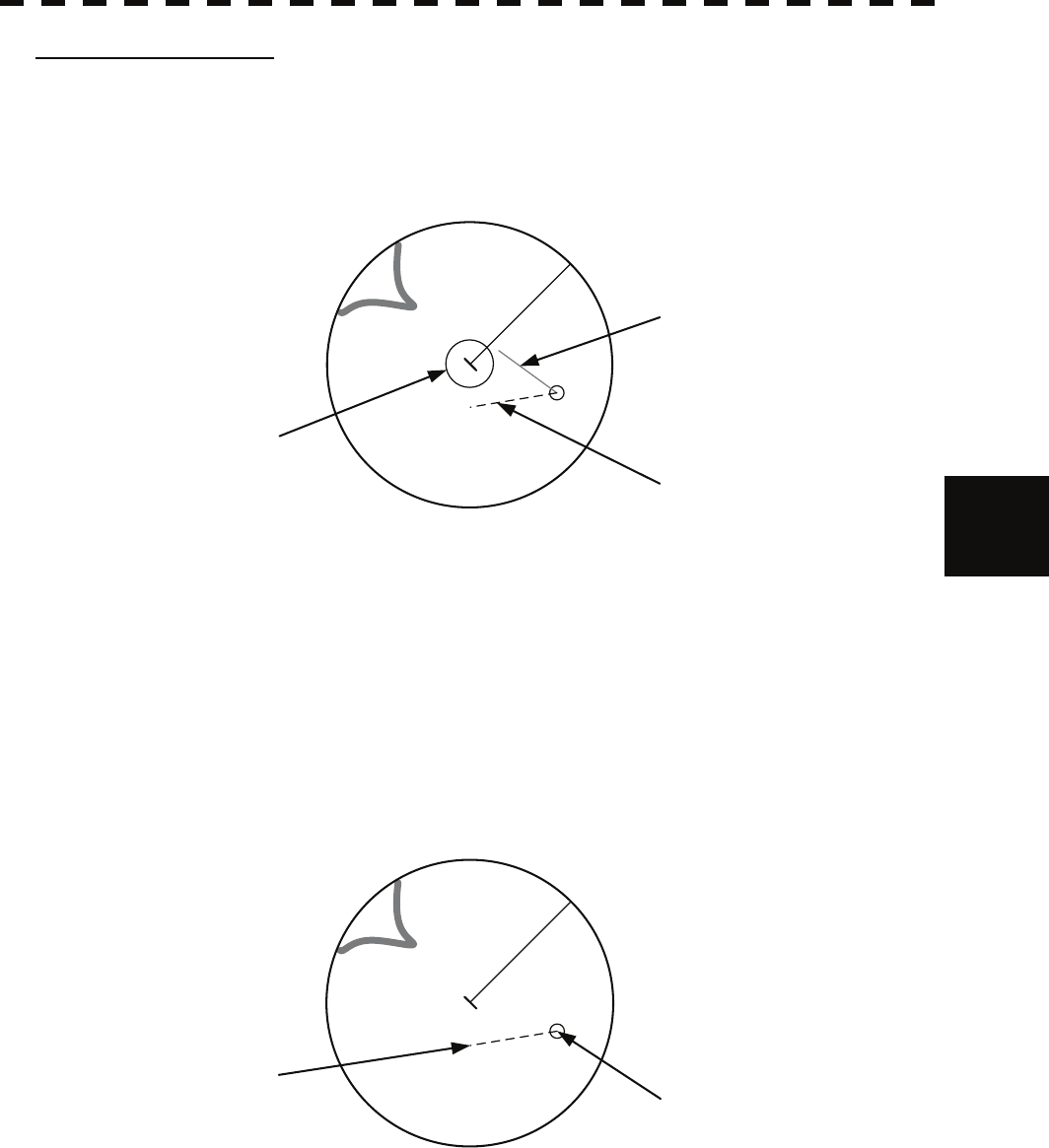
[I] Vector Mode Selection
True Vector Mode
In the true vector mode, the direction of a target vector indicates the true course of the target and its vector
length is proportional to its speed.
In this mode, own ship’s vector is displayed as shown below.
In this mode, the movements of other ships around own ship can be accurately and easily monitored.
However, CPA Ring cannot appear in this mode.
The relative vector is
not displayed
True vector
Own ship’s position HL
5-10
5.1 Preparation yy
yyy
5
Relative Vector Mode
The relative vector does not represent the true motion of the target, but its relative relation with own ship.
This means that a target with its relative vector directed to own ship (passing through the CPA Limit ring) will
be a dangerous target. In the Relative Vector mode, it can be seen at a glance where the CPA Limit of the
dangerous target is.
The true vector is
not displayed
Relative vector
CPA ring
HL
Therefore, the True / Relative mode shall optionally be used for the purpose of observation: the True vector
mode for grasping the true aspect of a target, and the Relative vector mode for grasping a target’s closest point
of approach (CPA).
[II] Vector Length (Vector Time)
The vector length of a target is proportional to its speed, and the vector time can be switched in a range of 1 to
60 minutes.
The diagram below illustrates a vector length of a target for 6 minutes, and the tip of the vector represents the
target’s position expected to reach 6 minutes later.
Current position
Future predicted position
(6 min later in this example)
HL
Refer to Section 5.1.7 Setting Vectors for how to change the vector time.

5-11
5.1.4 Cursor Modes (Cursor)
Types and Functions of Cursor Modes
The types of cursor modes are listed in the table below. To use the function of a cursor mode, move the cursor
onto the PPI object and press the [ENT] key.
Mode Function
ACQ TT Enables the target tracking function to acquire a target in manual mode.
ACT AIS Activates AIS targets, and sets a point filter.
TGT Data Displays the numeric data of a tracked target or AIS target.
CNCL TT Cancels a target tracking.
DEACT AIS Deactivates AIS target.
CNCL Data Hides the displayed numeric data of a tracked target or AIS target.
Mark Puts a temporary mark.
Property Displays the information of tracked targets, AIS targets, and marks.
AUTO Changes operation in accordance with the object at the cursor position.
Change of Cursor Mode
Procedures 1 Move the cursor to the cursor mode Cursor (upper right of the display
① on page 2-19), and press the [ENT] key. On the PPI, press the
[CLR / INFO] key and select a desired cursor mode from the list.
The selected cursor mode will be shown at the cursor mode (upper right of the display on
page 2-3).
Note: If the function of a selected cursor mode is not used for one minute or more, the cursor mode is
automatically changed to AUTO .

5-12
5.1 Preparation yy
yyy
5
Operation of AUTO Mode
As shown below, the AUTO mode performs operation in accordance with the object at the cursor position
when the [ENT] key is pressed.
Object at Cursor Position Operation
None Acquires a target.
EBL Performs EBL operation.
VRM Performs VRM operation.
Intersection point of EBL and VRM Performs EBL operation and VRM operation at the same time.
Parallel index line (PI) Operates the parallel index line.
Tracked target Displays the numeric data of the tracked target.
Tracked target with numeric data displayed Hides the numeric data.
Sleeping AIS target Activates the AIS target.
Activated AIS target Displays the AIS target information.
AIS target with numeric data displayed Hides the AIS target information.
Automatic acquisition / activation zone Operates the automatic acquisition / activation zone.
Sector radar alarm zone Operates the sector radar alarm zone.
AIS filter zone Operates the AIS filter zone.

5-13
z Set the optimum values of collision decision conditions,
depending upon vessel type, water area, weather and
oceanographic conditions.
(For the relations between those conditions and alarms,
refer to section 5.5 Alarm Display. )
5.1.5 Setting Collision Decision Criteria
Input of CPA Limit
Procedures 1 Move the cursor to the CPA limit setting (TT/AIS information ③ on page
2-23), and press the [ENT] key.
The CPA Limit value input screen will appear.
2 Enter the value to be set as a CPA limit.
For inputs to the value input screen, refer to Section 3.3.4.
Input of TCPA Limit
Procedures 1 Move the cursor to the TCPA limit setting (TT/AIS information ④ on page
2-23), and press the [ENT] key.
The TCPA Limit value input screen will appear.
2 Enter the value to be set as a TCPA limit.
For inputs to the value input screen, refer to Section 3.3.4.
5.1.6 Setting CPA Ring
While the distance of the specified CPA Limit value is used as the radius, the CPA ring is displayed with a red
circle.
Procedures 1 Move the cursor to the CPA ring display On / Off (lower right of the
display ⑦ on page 2-21), and press the [ENT] key.
The CPA ring will be displayed.
Note: The CPA ring is not displayed when the true vector mode is selected.
Attention

5-14
5.1 Preparation yy
yyy
5
5.1.7 Setting Vectors (Vector Time)
Vector time can be set in minutes in the range 1 to 60 min.
A true vector mode or relative vector mode can be selected.
Setting vector time on the display
Procedures 1 Move the cursor to the target vector time setting (TT / AIS information ②
on page 2-23), and press the [ENT] key.
The Vector Time value input screen will appear.
2 Enter the value to be set as vector time.
For how to input numeric data on the numeric value input screen, see Section 3.3.4.
Setting vector time using the multi-dial [MULTI]
Procedures 1 Press the [MULTI] dial several times to activate the Vector mode.
Vector will be displayed in the multi-dial mode (lower left of the display on page 2-3).
2 Turn the [MULTI] dial to set the vector time.
Setting vector mode [VECT R / T]
Procedures 1 Press the [VECT R / T] key.
The current vector mode T (true vector) or R (relative vector) will be displayed in
the target vector display true / relative switching (TT / AIS information ① on page 2-23).

5-15
z If offset ranges are not set correctly, AIS symbols and
radar echoes may be displayed shifted.
z When offset ranges are set, latitude and longitude data
received from the GPS is offset, and the offset data is
displayed as the latitude and longitude of own ship’s
position.
5.1.8 Setting the GPS antenna location
Set the GPS antenna location. Set offset ranges in longitudinal direction and latitudinal direction from the
own ship's reference position.
For the setting procedure, refer to Section 7.1.9 Setting of CCRP/Antenna/GPS Antenna Position.
Attention
5-16
5.2 Target Tracking Operation yy
yyy
5
5.2 TARGET TRACKING OPERATION
This section explains how to use the target tracking function.
The target tracking function automatically tracks a target, and displays the target's course and speed as
vectors.
The target tracking function calculates CPA and TCPA, and issues an alarm as needed.
The tracking data is erased from memory when the power is turned off or during transmission standby.
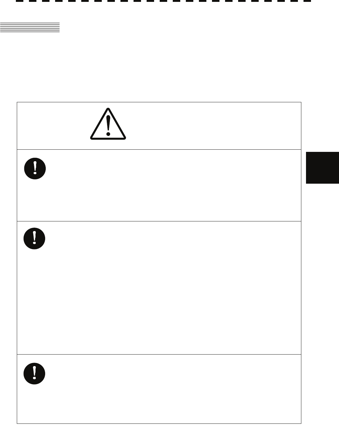
CAUTION
Use the radar only as a navigation aid.
The final navigation decision must always be made by the
operator him/herself.
Making the final navigation decision based only on the
radar display may cause accidents such as collisions or
running aground.
Use target tracking function only as a navigation aid. The
final navigation decision must always be made by the
operator him/herself.
Making the final navigation decision based only on tracking
target information may cause accidents.
Tracking target information such as vector, target numerical
data, and alarms may contain some errors. Also, targets
that are not detected by the radar cannot be acquired or
tracked.
Making the final navigation decision based only on the
radar display may cause accidents such as collisions or
running aground.
In setting an automatic acquisition zone, it is necessary to
adjust the gain, sea clutter suppression and rain clutter
suppression to ensure that target echoes are displayed in
the optimum conditions. No automatic acquisition zone
alarms will be issued for targets undetected by the radar,
and this may cause accidents such as collisions.

5-17
5.2.1 Acquiring Target [ACQ]
Target acquisition can be performed on two modes, Automatic and Manual, and both modes can be used at
the same time.
Automatic acquisition
Note: If the number of targets being tracked has reached the allowable maximum and other targets
(not being tracked) go into the acquisition/activation zone, automatically acquired targets are
canceled in ascending order of danger.
The position of the scanner shall be at the centre of the azimuth or range in the
acquisition/activation zone.
Turning On / Off the automatic acquisition and AIS activation (AZ Menu)
Procedures 1 Press the [AZ] key for two seconds.
The AZ Menu will appear.
2 Press the [1] or [2] key.
The acquisition / activation zone 1 (AZ1) or acquisition / activation zone 2 (AZ2) will
be set to on or off.
On :The acquisition / activation zone is turned on.
The mark " " and target ID number are put to an acquired target and
move
with the target. The vectors are displayed within 1 minute.
AIS targets are activated.
Off :The acquisition/activation zone is turned off.
The acquisition/activation zone will disappear from the radar display, but the
system continues to track the acquired target.
The activated AIS targets remain activate.
5-18
5.2 Target Tracking Operation yy
yyy
5
Creating the automatic acquisition and AIS activation Zone
Procedures 1 Press the [AZ] key for 2 seconds.
The AZ Menu will appear.
2 Open the Make AZ menu by performing the following menu operation.
3. Make AZ
3 Press [1] or [2] key.
The range setting of the acquisition / activation zone 1 (AZ1) or acquisition /
activation zone 2 (AZ2) will be started.
4 Set the starting azimuth and range by turning the [EBL] dial and
[VRM] dial, and press the [ENT] key.
5 Set the ending azimuth and range by turning the [EBL] dial and
[VRM] dial, and press the [ENT] key.
The acquisition / activation zone will be determined.
Setting the [AZ] key allocation (Set AZ Key)
A generally used acquisition / activation zone can be turned on / off by simply pressing the [AZ] key.
Procedures 1 Press the [AZ] key for 2 seconds.
The AZ Menu will appear.
2 Open the AZ menu by performing the following menu operation.
5. Set AZ Key
→ 1. AZ
3 Set the assignment of the key.
On :Pressing the [AZ] key turns on / off the acquisition / activation zone.
Off :Pressing the [AZ] key does not turn on the acquisition / activation zone.
Note: If the RADAR Alarm key assignment is set, pressing the [AZ] key turns on / off the Acquisition
Zone at the same time the RADAR Alarm is turned on / off.
5-19
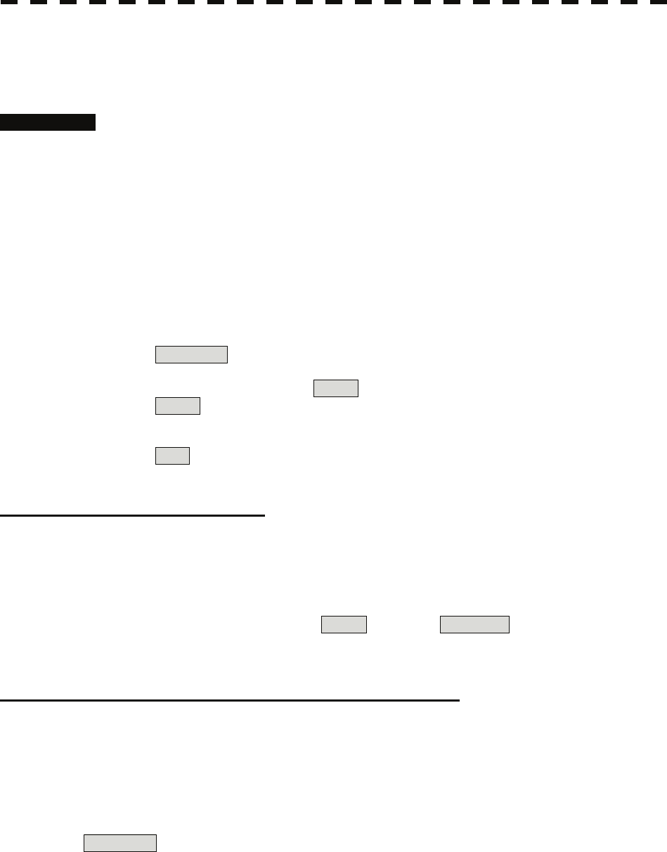
Manual Acquisition [ACQ]
Note: If more targets are acquired manually in the condition that the maximum number of targets are
under tracking, the targets cannot acquired.
Procedures 1 Move the cursor onto the target to be acquired, and press the [ACQ]
key.
The target will be acquired and the initial acquisition symbol will be displayed.
The vector will be displayed within one minute.
Target manually acquired.
The initial acquisition symbol is displayed.
Target that has passed for 1 min.
The acquisition symbol and vector are displayed.
To perform operation only in the manual acquisition mode without automatic
acquisition/activation, turn off the automatic acquisition/activation function.
Use of Automatic and Manual Acquisition Modes
Use the manual acquisition mode while the automatic acquisition mode is on.
Manually acquire the target to which particular attention should be paid, and get the other targets
automatically acquired. If a new target appears exceeding the maximum number of targets, the manually
acquired target is displayed even in the background until it gets out of the display. However, automatically
acquired targets are canceled starting far distance from own ship.

5-20
5.2 Target Tracking Operation yy
yyy
5
5.2.2 Canceling Unwanted Tracked Targets [TGT CNCL]
Unwanted tracked targets can be canceled one by one in the following cases:
• Tracking is no longer necessary for targets with which vectors/symbols are displayed after being acquired
and tracked.
• The number of vectors on the radar display needs to be reduced for easy observation.
When targets are to be re-acquired from the beginning, all the current vectors can also be canceled.
Canceling targets one by one [TGT CNCL]
Procedures 1 Put the cursor on the tracked target to the desired for canceling target,
and press the [TGT CNCL] key.
The vectors and symbols of the tracked targets will disappear, and only the radar video
remain.
Canceling all targets collectively [TGT CNCL]
Procedures 1 Press the [TGT CNCL] key for 5 seconds.
The vectors and symbols of all the targets will disappear, and only the radar videos
remain.
Note: When all the targets have been canceled, the system stops tracking them. Thus, you need to
re-acquire targets in manual or automatic acquisition mode. Do not cancel all the targets unless
otherwise required.
5-21
z When a target or own ship changes its course, or when
a new target is acquired, its vector may not reach a
given level of accuracy until 3 minutes or more has
passed after such course change or target acquisition.
Even if 3 minutes or more has passed, the vector may
include an error depending upon the tracking
conditions.
5.2.3 Tracked Target Data Display [TGT DATA]
Type of Data Display (Target Information)
Target Data
Target identification (TT ID) ID number of the target
True bearing (BRG) 0.1° unit
Range 0.01 NM unit
Course 0.1° unit
Speed 0.1 knot unit
Closest point of approach (CPA) 0.01 NM unit
Time to CPA (TCPA) 0.1 min unit
Bow crossing range (BCR) 0.01 NM unit
Bow crossing time (BCT) 0.1 min unit
The target for which its numeric data is displayed is marked with a symbol " " to distinguish from
other targets.
If a target’s data is displayed, but without the symbol " " , such a target exists outside the currently
displayed radar display.
Method of Displaying Numeric Data [TGT DATA]
Procedures 1 Put the cursor on the tracked target for which numeric data is to be
displayed, and press the [TGT DATA] key.
Then, the data of the designated target will appear, it will be marked with a symbol
" ". The target data will remain on the radar display until the target is lost and
its vector disappears, or until another target is designated.
If a target with the mark " " is designated, only its true bearing and range will
appear until its vector appears.
Attention

5-22
5.2 Target Tracking Operation yy
yyy
5
Cancellation of Numeric Data Display (CNCL Data)
Procedures 1 Put the cursor on the tracked target with which numeric data is
displayed, and press the [CLR / INFO] key.
The cursor mode list will appear.
2 Press the [6] key.
The numeric value will disappear.
5.2.4 Displaying Target ID No. (Target Number Display)
A target ID number is a value displayed beside the acquisition symbol when a target is acquired.
A target ID number 1 to 100 is assigned to each target in acquisition order. Once a target ID number is
assigned, it identifies the target until the target is lost or the target acquisition is canceled.
Procedures 1 Press the [TT MENU] key.
2 Press the [4] key.
Target Number Display will appear.
3 Press the [numeric] key corresponding to the display method to be
set.
On :Displays target ID numbers.
Off :Hides target ID numbers.
Target Track :Displays target ID number with target track.
If there are many tracking targets and their symbol display is confusing, set Target
Number Display to off to view the radar display easily.
Note: An ID number is always displayed for only targets with which numeric data is displayed.
5-23
5.2.5 Adding Tracked Target ID Name (Name)
The system can enter a name for each of tracking targets that have been acquired.
Procedures 1 Put the cursor on the tracked target, and press the [CLR / INFO] key.
The cursor mode list will appear.
2 Press the [8] key.
The TT Target Information will appear.
3 Press the [1] key.
The setting items for ship name (Name) will be displayed.
4 Select the input method.
Data Base : Selection of one of previously input ship names.
When this method is selected, a list of ship names that have been input
by selecting Input will be displayed.
Input : Input of a new ship name.
When this method is selected, the ship name (Name) input window
will open.
Off : Target ship's name is not displayed.
Entering a new ship name (Input)
5 Input a new ship name.
Up to 8 characters can be input as a ship name.
For the input method on the character input screen, see Section 3.3.4.
The input name by selecting Input is saved in Data Base .
Selecting one of previously input ship names (Data Base)
5 Press the [numeric] key corresponding to the ship name to be
selected.
The selected ship name will be entered.
* Data Base can contain 30 ship names.
5-24
5.2 Target Tracking Operation yy
yyy
5
z The reference target function is to be used if the own
ship's speed cannot be displayed normally due to trouble
such as a speed sensor malfunction. Do not use the
reference target function except in emergencies.
z If the speed or course of the own ship is changed or a new
reference target is set, the displayed speed may take 3
minutes or more to reach the specified speed after the
speed / course change or the setting.
Even after 3 minutes or more has passed, the speed may
differ from the specified speed depending on the tracking
condition.
z If a large radar echo such as a land target is set as a
reference target, the vectors of the speed and other
tracking targets will not be displayed correctly and may
cause an accident.
z If a sailing ship is set as a reference target, the vectors of
the speed and other tracking targets will not be displayed
correctly and may cause an accident.
z If the REF. is selected for the speed sensor, the AIS
function cannot be turned on.
z If the reference target is lost or the target tracking
function is stopped, the speed sensor is placed in manual
mode MAN .
z The loss of a reference target may have a major impact on
the accuracy of the results for true speed and true course
of the target and that own speed will be degraded.
z The reference targets are only used for the calculation of
true speed.
5.2.6 Reference Target (Reference)
The system can display the own ship's speed. To do so, it sets a reference target by tracking a target for
which ground fixed.
Attention

5-25
Procedures 1 Tracking a target for which ground fixed.
2 Put the cursor on the tracked target, and press the [CLR / INFO] key.
The cursor mode list will appear.
3 Press the [8] key.
The Property will appear.
4 Press the [3] key.
The reference target function will be set to on or off.
On :A reference target is set.
Off :The reference target is canceled.
5 Put the cursor on the speed sensor switching (Own ship information
② on page 2-22), press the [ENT] key, and select REF. .
The speed of own ship calculated from the reference target will be displayed.
When a reference target is set, the symbol display is changed to " R ".
Only one target can be set as a reference target.
When a new reference target is set, the previously set reference target is canceled.
Note: If AIS function is set to on, the reference target function cannot be used.
5-26
5.2 Target Tracking Operation yy
yyy
5
5.2.7 Operation Test (TT Test Menu)
CAUTION
Target Tracking Function Test is provided to test if the
target tracking function is operating normally. Thus, do
not use the function except when you test the target
tracking function.
In particular, if the operation test mode is used during
navigation, pseudo targets appear on the radar display and
they are confused with actual targets.
Do not use the mode during navigation.
Otherwise, an accident may result.
The following functions are available for testing the target tracking function:
[I] Test Video Makes an operation check on the target detection circuit.
[II] TT Simulator Generates pseudo targets on the radar display in order to test if the target
tracking function is operating normally.
[III] Status Displays the status of the target tracking function.
[IV] Gate Display Displays the gate size for acquiring / tracking a target.

5-27
[I] Test Video
Test Video is used to check whether the video signals under target acquisition and tracking are inputted to
and processed in the target detection circuit normally.
However, it is sufficient to check that VDH in Test Video is displayed.
Note: Test Video may not be displayed for a target which is not yet acquired or tracked. Test Video may
not be displayed either if the [GAIN] dial or [SEA] dial is not properly adjusted.
Procedures 1 Press the [TT MENU] key.
2 Open the TT Test Menu by performing the following menu operation.
9. TT Test Menu
3 Press the [1] key.
The setting items for Test Video will be displayed.
4 Select the test video to be displayed.
In general, VDH is sufficient for target display checks in test video mode.
If any target displayed clearly in the radar display is not displayed in the Test Video mode, the target
detection circuit of the Target Tracking unit may have a trouble
Cancellation 1 Press the [1] key while the TT Test Menu is displayed.
The setting items for Test Video will be displayed.
2 Press the [1] key
The test video display will be turned off.
5-28
5.2 Target Tracking Operation yy
yyy
5
[II] Target Tracking Simulator
Pseudo targets can be generated in certain known positions to check whether the target tracking units are
operating normally. Since the pseudo targets move depending on known parameters, the values for these
pseudo targets can be compared with the known value if the pseudo targets are acquired and tracked, and
displayed. Thus, it can be checked if the system is operating normally.
Procedures 1 Press the [STBY] key.
The equipment will enter the transmission standby state.
2 Press the [TT MENU] key.
3 Open the TT Test Menu by performing the following menu operation.
9. TT Test Menu
4 Press the [2] key.
The setting items for TT Simulator will be displayed.
5 Select the scenario to be set.
The TT Simulator display will be turned on.
6 Press the [TX / PRF] key.
When the TT simulator is active, the character " X " will display at the bottom of the
radar display.
Target tracking simulator / scenario
Target start point Target end point
Scenario Distance Bearing Distance Bearing
Pseudo-target speed
1 3.2 nm 20 ° 1 nm 90 ° 20 kn
2 6 nm 0 ° 0 nm 0 ° 10 kn
3 6 nm every 18 °1 nm every 18 °10 kn
4 6 nm 45 ° 1 nm 45 ° 105 kn
5 6 nm 45 ° 6 nm 150 ° 20 kn
6 6 nm 45 ° 6 nm 150 ° 20 kn
Note: When the simulator is operating, set 0 ° as the heading bearing, and 0 kn as the speed of own ship.
When the range between own ship and the pseudo target is 0, the target will disappear.
Cancellation 1 Press the [STBY] key.
The equipment will enter the transmission standby state.
2 Press the [2] key while the TT Test Menu is displayed.
The setting items for TT Simulator will be displayed.
3 Press the [1] key.
The TT Simulator display will be turned off.

5-29
[III] Status display (Status)
The current Target Tracking status will appear.
Procedures 1 Press the [TT MENU] key.
2 Open the TT Test Menu by performing the following menu operation.
9. TT Test Menu
3 Press the [3] key.
The setting items for Status will be displayed.
*Constant : Vector response
*VID Level TD : Threshold value used for automatic
acquisition
*VID Level High : Threshold value used for tracking
*VID Level Low : Unused
*Gate Size : Size of gate used for tracking
*Tracking : Number of targets currently acquired
5-30
5.2 Target Tracking Operation yy
yyy
5
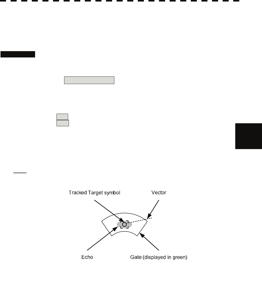
[IV] Gate Display
The gate displays an area monitoring a target using the Target Tracking function. This radar equipment
allows the gate size to change automatically according to target range and size. User can check the gate
size using the following function.
Procedures 1 Press the [TT MENU] key.
2 Open the TT Test Menu by performing the following menu operation.
9. TT Test Menu
3 Press the [4] key.
The gate display mode is switched.
On : Gate is displayed
Off : Gate is not displayed
4 Display the numeric value of a target according to Section 5.2.3.
The numeric value of the target will be displayed, and the tracked target symbol will
be enclosed in a green gate.
Note: The Target Tracking can display the gate of two targets simultaneously.
5-31
z When the AIS function is set to Off, the AIS display
function is turned off and AIS symbols are no longer
displayed.
z Once the AIS display function is set to Off, it is not
automatically switched to On even if a dangerous
target exists.
5.3 AIS OPERATION
5.3.1 Restrictions
The following restrictions are placed on use of the AIS function.
• The AIS function is unavailable in the following cases:
a) MAN or REF. is selected for the speed sensor.
b) The current offset (Set/Drift Setting) is set while LOG or 2AXW is selected for the speed
sensor.
c) The GPS geodetic system is used except WGS-84.
• LOG or 2AXW cannot be selected for the speed sensor in the following case:
The AIS function is turned on and the current offset (Set/Drift Setting) is selected.
• MAN cannot be selected for the speed sensor in the following case:
The AIS function is On.
• Current offset (Set/Drift Setting) cannot be turned On in the following case:
LOG or 2AXW is selected for the speed sensor while the AIS function is on.
5.3.2 Setting AIS Display Function (AIS Function)
Procedures 1 Put the cursor on the AIS On / Off (TT / AIS information ⑧ on page
2-23), and press the [ENT] key.
The received AIS information will be shown on the radar display.
Attention

5-32
5.3 AIS Operation yy
yyy
5
5.3.3 Activate AIS Targets (Activate AIS)
Activate an AIS target, and display the target’s vector and make a collision decision.
Manual activation (ACT AIS)
Activate an AIS target in manual mode to display the vector and heading line.
Procedures 1 Put the cursor on the AIS symbol to be activated, and press the
[CLR/INFO] key.
The setting items for cursor modes will be displayed.
2 Press the [2] key.
The selected AIS target will be activated.
Automatic activation (AUTO Activate)
Activate an AIS target in automatic mode to display the vector and heading line.
When the automatic activation function is used, AIS targets are automatically activated when they go into
the automatic activation zone. The automatic activation zone is identical to the automatic acquisition zone
(AZ) used for target tracking. For the zone setting, refer to " Acquiring Target " in Section 5.2.1
The position of the scanner shall be at the centre of the azimuth or range in the acquisition/activation zone.
If there are more AIS targets than the allowable maximum, they are deactivated in the low-priority (See the
section 5.1.2).
Reference If an AIS target is activated but the vector is not displayed, refer to " Displaying Target ID
Number " in section 5.3.6
5.3.4 Deactivate AIS Targets (Deactivate AIS)
Deactivate an AIS target and clear the display of the vector and heading line.
Procedures 1 Put the cursor on the AIS target to be deactivated, and press the
[CLR/INFO] key.
The setting items for cursor modes will be displayed.
2 Press the [5] key.
The selected AIS target will be deactivated.
Note: This operation is available only for an activated AIS target.

5-33
5.3.5 Displaying AIS Information [TGT DATA]
Types of information displayed
There are two modes (simple and detail) to display AIS target information. The display items are
determined by the selected mode.
Display Item Detail mode Simple mode
NAME (ship name) Up to 20 characters
Call Sign Up to 7 characters
MMSI Up to 9 characters
COG (course over ground) or CTW (course through water) 0.1 ° unit
SOG (speed over ground) or STW (speed through water) 0.1 knot unit
CPA (closest point of approach) 0.01 nm unit
TCPA (time to CPA) 0.1 min unit
BRG (true bearing) 0.1 ° unit
Range 0.01 nm unit
HDG (heading bearing) 0.1 ° unit
ROT (rate of turn) 0.01 °/min
POSN (latitude / longitude) 0.0001’ unit
Destination (waypoint) Up to 20 characters
NAV Status Status (number)
Not displayed
If the numeric information of ROT is blank, the radar is receiving the AIS data which is cannot displayed.
In this case, you can only trust the turning direction which is indicated by the turn indicator. The turn
indicator is displayed on the AIS symbol as the line perpendicular to the heading direction. (See the
Section 5.1.2 "Types and Definitions of AIS Target Symbols")
If the numeric information of SOG or STW is 102.2kn, the target ship's speed is 102.2kn or over. Then the
system cannot calculate CPA and TCPA. Therefore, missing is indicated in the CPA and TCPA
information.
The detail mode displays the numeric data of only a single ship, the simple mode can display the numeric
data of up to two ships.
For NAV Status, one of the following statuses is displayed in accordance with Navigation Status:
No. Status
0 Under Way Using Engine
1 at Anchor
2 Not Under Command
3 Restricted Maneuverability
4 Constrained by Her Draft
5 Moored
6 Aground
7 Engaged in Fishing
8 Under Way Sailing
9 Reserved
10 Reserved
11-14 Reserved
15 Not Defined

5-34
5.3 AIS Operation yy
yyy
5
Displaying AIS Target Information [TGT DATA]
Procedures 1 Put the cursor on the AIS target of which information is to be
displayed , and press the [TGT DATA] key.
The information of the selected AIS target will be displayed.
Reference: When the numeric data of a target is displayed but the mark " " is not on the radar
display, the target is outside the display.
Canceling AIS Target Information Display (CNCL Data)
Procedures 1 Put the cursor on the activated AIS target of which information
display is to be cancelled, and press the [CLR / INFO] key.
The setting items for cursor modes will be displayed.
2 Press the [6] key.
The information display of the selected AIS target will be cleared.
Selecting Detail / Simple Mode for AIS Target Information Display
Procedures 1 Put the cursor on the detail/simple display switching (AIS target
information ① on page 2-25), and press the [ENT] key.
The detail or simple mode display for AIS target information will be selected.
5-35
Message
Received AIS messages can be displayed.
Up to 10 messages of addressed message and up to 10 messages of broadcast message can be displayed.
If the number of messages exceeds 10, the oldest received messages are sequentially deleted.
Displaying Message Selected from List (Message)
Procedures 1 Press the [RADAR MENU] key twice.
2 Open the Message menu by performing the following menu operation.
7. AIS Menu
→ 7. Message
3 Press the [1] or [2] key.
Pressing [1] key lists addressed messages; pressing [2] key lists broadcast messages.
Each list shows ship names and message-received time.
For an unread message, * is displayed to the left of the item number.
4 Press the [numeric] key corresponding to the message to be
displayed.
The message will appear.
Displaying Specified Target's Message
Procedures 1 Display AIS target information.
If there are messages from the target, a message mark will be displayed in the unread
message display field (AIS target information ② on page 2-25).
2 Put the cursor on the unread message display (AIS target information
in ② on page 2-25), and press the [ENT] key.
The message will appear.
Deleting Message (Delete)
Procedures 1 Press the [1] key while the message is displayed.
The Confirmation Window will appear.
2 Press the [1] key.
The message will be deleted, and the ship name and message-received time will
disappear from the list.
5-36
5.3 AIS Operation yy
yyy
5
Displaying Data of Lost AIS Target (Display Lost TGT Data)
The data of the last-lost AIS target can be displayed.
The data of only one target that has been lost most recently can be displayed.
Procedures 1 Press the [RADAR MENU] key twice.
2 Open the Display Lost Target Data menu by performing the following
menu operation.
7. AIS Menu
→ 8. Display Lost TGT Data
The data of the last-lost AIS target will be displayed.
Displaying Own Ship's AIS Data (Own Ship's AIS Data)
The AIS data of own ship can be displayed.
Procedures 1 Press the [RADAR MENU] key twice.
2 Open the Own Ship's AIS Data menu by performing the following
menu operation.
7. AIS Menu
→ 9. Own Ship’s AIS Data
The own ship's AIS data will be displayed.
5-37
5.3.6 Displaying Target ID No. (Target Number Display)
When an AIS target is activated, a target ID number is displayed next to the AIS target symbol.
A target ID number 1 to 100 is assigned to each target in activation order. Once a target ID number is
assigned, it identifies the target until the target is lost or deactivated.
Procedures 1 Press the [RADAR MENU] key twice.
2 Open the Target Number Display menu by performing the following
menu operation.
7. AIS Menu
→ 5. Target Number Display
3 Press the [numeric] key corresponding to the display method to be
set.
On : Displays target ID numbers.
Off : Hides target ID numbers.
Target Track : Displays target ID number with AIS track.
Ship's Name : Displays the ship's name.
If there are many tracking targets and their symbol display is confusing, set Target
Number Display to off to view the radar display easily.
Note: An ID number or ship's name is always displayed for only targets with which numeric value is
displayed.
5.3.7 Setting AIS Filter (AIS Filter Setting)
About an AIS filter
By setting an AIS filter, an AIS target in the area can be displayed by priority or only the targets in the area
can be displayed. An AIS filter is initially set in a circle having a radius of 20 [nm] from the CCRP. If
301 or more AIS targets exist in the filter range, they are displayed in the priority order explained in Section
5.1.2 Symbols - Types and Definitions of AIS Target Symbols.
Types of AIS Filters (Filter Type)
There are the following 3 types of AIS filters:
Range :A filter is set in a circle with a set range as the radius.
Sector :A filter is set in a sector formed by two bearings with the bow as reference.
Zone :A filter is set in a zone formed by two bearings and two ranges with the bow as reference.
Procedures 1 Put the cursor on the AIS filter mode switching (TT / AIS information
⑫ on page 2-23), and press the [ENT] key to select the filter to be
set.
The AIS filter will be selected.
5-38
5.3 AIS Operation yy
yyy
5
Creation of AIS Filter (Make AIS Filter)
Procedures 1 Press the [RADAR MENU] key twice.
2 Open the AIS Filter Setting menu by performing the following menu
operation.
7. AIS Menu
→ 4. AIS Filter Setting
3 Press the [2] key.
The mode to make an AIS filter will be activated.
[I] Setting Range Filter
4 Set a filter range by turning the [VRM] dial, and press the [ENT] key.
[II] Setting Sector Filter
4 Set a starting bearing by turning the [EBL] dial, and press the [ENT]
key.
5 Set an ending bearing by turning the [EBL] dial, and press the [ENT]
key.
[III] Setting Zone Filter
4 Set a starting bearing and range by turning the [EBL] dial and [VRM]
dial, and press the [ENT] key.
5 Set an ending bearing and range by turning the [EBL] dial and [VRM]
dial, and press the [ENT] key.
Note: When the automatic activation function is enabled, the filter range is automatically changed for
covering the automatic activation zone. Thus, the automatic activation zone is always within the
filter range.
AIS Filter Display On/Off (Filter Display)
Procedures 1 Press the [RADAR MENU] key twice.
2 Open the AIS Filter Setting menu by performing the following menu
operation.
7. AIS Menu
→ 4. AIS Filter Setting
3 Press the [3] key.
Filter Display will be set to on or off.
5-39
Display of Targets outside AIS Filter (Filter Mode)
Procedures 1 Press the [RADAR MENU] key twice.
2 Open the Filter Mode menu by performing the following menu
operation.
7. AIS Menu
→ 6. Filter Mode
3 Press the [6] key.
The Filter Mode is switched.
Display : Displays only AIS targets in the AIS filter.
Priority : Displays AIS targets in the AIS filter by priority, and also displays
targets outside the AIS filter.
Note: Activated AIS targets can be displayed even when they are outside the AIS filter.
Point Filter
AIS targets which are not displayed because they are outside the AIS filter or at low priority levels can be
activated by giving a higher priority to them.
Procedures 1 Put the cursor on the position where a point filter is to be set, and
press the [CLR / INFO] key to select the filter to be set.
The setting items for cursor modes will be displayed.
2 Press the [2] key.
A point filter will be set at the cursor position.
If an AIS target is in the point filter, it will be activated.
When an AIS target is activated or an AIS target is not found within one minute, the
point filter will be cleared.
Note: The point filter's range is 1 nm, and cannot be changed.

5-40
5.3 AIS Operation yy
yyy
5
5.3.8 Conditions for Deciding AIS Target to be Lost
About a lost target
When the data of an AIS target cannot be received for a specified time, the target is decided to be lost and
the target data is deleted. As shown in the table below, the time until target data is deleted varies
depending on the class of receive data and the target status.
Deciding AIS Target to be Lost
Time until data deletion
Target status SOLAS ship
(Class A) SOLAS ship
(Class B)
Vessel below 3 knots (Class A) or 2 knots (Class B) and it is
now at anchor or on the berth 18 min 18 min
Vessel of 3 knots or more and it is now at anchor or on the berth 60 sec 18 min
Vessel of 0 to 14 knots (Class B: 0 to 14 knots) 60 sec 180 sec
Vessel of 14 to 23 knots 36 sec 180 sec
Vessel of 23 knots or more 30 sec 180 sec
SAR (Search and Rescue) 60 sec 60 sec
ATON (Aid to Navigation) 18 min 18 min
Base Station 60 sec 60 sec
Reference: When a dangerous target ship is lost, a lost alarm is issued and the symbol changes to a lost
symbol. The lost symbol will display continuously on the last-received position.
If the [ALARM ACK] key is pressed, the symbol is cleared.
5-41
5.3.9 Setting Conditions for AIS Alarm (AIS Alarm Setting)
Conditions for issuing a Lost alarm and CPA/TCPA alarm for AIS targets can be set.
Setting of Condition for Lost Alarm
Procedures 1 Press the [RADAR MENU] key twice.
2 Open the AIS Alarm Setting menu by performing the following menu
operation.
7. AIS Menu
→ 6. AIS Alarm Setting
3 Press the [1] key.
The setting items for Lost Alarm will be displayed.
4 Press the [numeric] key corresponding to the condition to be set.
Off : A lost alarm is not issued.
Danger : A lost alarm is issued only for AIS targets for
which a dangerous target alarm has been issued.
ACT&Danger : A lost alarm is issued only for activated AIS
targets and AIS targets for which a dangerous
target alarm has been issued.
ACT&Danger&Select : A lost alarm is issued only for activated AIS
targets, data indicated AIS targets and AIS targets
for which a dangerous target alarm has been issued.
Note: A lost alarm is not issued for sleeping AIS targets.
Setting of Condition for CPA/TCPA Alarm
Procedures 1 Press the [RADAR MENU] key twice.
2 Open the AIS Alarm Setting menu by performing the following menu
operation.
7. AIS Menu
→ 6. AIS Alarm Setting
3 Press the [2] key.
The setting items for CPA/TCPA Alarm is switched.
Off : A CPA/TCPA alarm is not issued.
ACT : A CPA/TCPA alarm is issued only for activated AIS targets.
ACT&Sleep : A CPA/TCPA alarm is issued for all AIS targets on the radar
display.
Note: When the Lost Alarm menu set to Off, the CPA ring color changes to dark color.
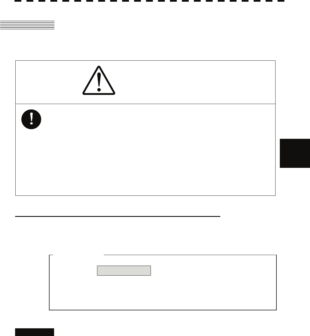
5-42
5.4 Decision of Targets as Identical yy
yyy
5
z Turn off Association in order not to make a decision
on if targets are identical, or in order to display
symbols that have disappeared.
5.4 DECISION OF TARGETS AS IDENTICAL
(ASSOCIATION)
CAUTION
If a great value is set as a condition for deciding targets as
identical, a tracking target near an AIS target is regarded as
identical to the AIS target and it may not be displayed any
more.
For example, when a pilot boat (which is a small target not
being tracked) equipped with an AIS function approaches a
cargo ship as a tracking target not equipped with an AIS
function, the tracking target symbol of the cargo ship may
not be displayed any more.
Setting of Function to Decide Targets as Identical (Association)
When an AIS target and a tracking target are decided to be identical, an association symbol is displayed for
the targets regarded as identical. In this case, the AIS target symbol is automatically activated.
Procedures 1 Put the cursor on the association On/Off (TT/AIS information ⑪on
page 2-23), and press the [ENT] key.
Association will be set to on or off.
Attention
5-43
Setting of Conditions for Deciding AIS and Tracked Targets as Identical
(Association Setting)
Procedures 1 Press the [TT MENU] key.
2 Press the [1] key.
The Association Setting menu will appear.
3 Select and enter the item to be set.
Conditions for deciding targets as identical will be set. When the differences of all
item between AIS and tracked target are under the set conditions..
Once regard as identical, when one of the differences exceed 125 % of the set
condition, they are regarded as dissidence.
* The setting for this function is common to Association Setting in the AIS Menu.
Types of Decision Conditions to be Set
Decision conditions
1. Association On / Off (Function to decide targets as identical)
2. Priority AIS / TT (Symbol to be displayed)
3. Bearing 0.0 to 9.9 °
4. Range 0 to 999 m
5. Course 0 to 99 °
6. Speed 0 to 99 kn
7.Applicable AIS Target ACT or ACT&Sleep (activated AIS target or all AIS
target)
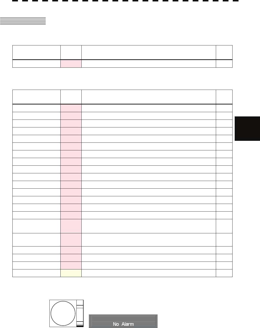
5-44
5.5 Alarm Display yy
yyy
5
5.5 ALARM DISPLAY
Critical alarm messages for Target Tracking (TT) and AIS functions:
Message Class Description ALR
No.
CPA/TCPA Alarm There is a dangerous target. 301
Alarm messages for Target Tracking (TT) and AIS functions:
Message Class Description ALR
No.
AIS Alarm *** Alarm AIS alarm (Up to 10 alarm messages can be displayed.).
AIS Alarm 001 Alarm Tx malfunction
AIS Alarm 002 Alarm Antenna VSWR exceeds limit
AIS Alarm 003 Alarm Rx channel 1 malfunction
AIS Alarm 004 Alarm Rx channel 2 malfunction
AIS Alarm 005 Alarm Rx channel 70 malfunction
AIS Alarm 006 Alarm general failure
AIS Alarm 008 Alarm MKD connection lost
AIS Alarm 025 Alarm external EPFS lost
AIS Alarm 026 Alarm no sensor position in use
AIS Alarm 029 Alarm no valid SOG information
AIS Alarm 030 Alarm no valid COG information
AIS Alarm 032 Alarm Heading lost/invalid
AIS Alarm 035 Alarm no valid ROT information
CPA/TCPA Alarm There is a dangerous target. 301
Lost Alarm Failure in tracking the target that has been under tracking.
Failure in receiving AIS target data for a specified time.
New Target Alarm Acquisition or activation of a target in the automatic acquisition /
activation zone. 302
RADAR Alarm (In) Alarm Targets have entered the radar alarm range.
RADAR Alarm (Out) Alarm Targets have left the radar alarm range.
REF Target Alarm Decrease in the reference target accuracy.
Trial Warning There is a dangerous target, when trial maneuver is active.
An alarm is displayed in the alarm indication (Alarm on page 2-9)
See also section 9.1.1 "List of Alarm Indications".
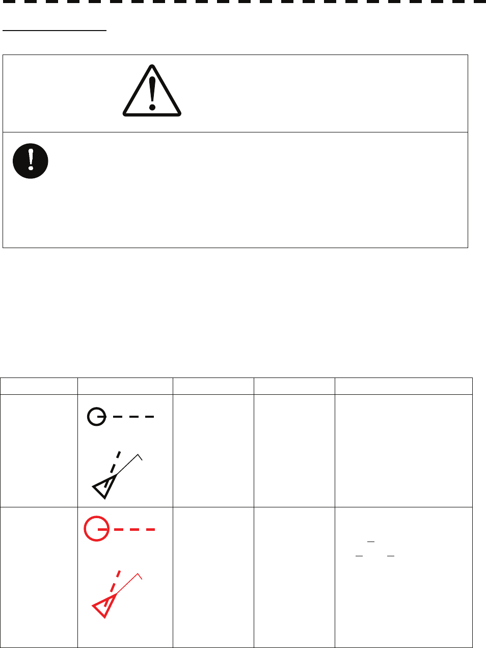
5-45
CPA / TCPA Alarm
CAUTION
Since these alarms may include some errors depending on
the target tracking conditions, the navigation officer himself
should make the final decision for ship operations such as
collision avoidance.
Making the final navigation decision based only on the
alarm may cause accidents such as collisions.
In the system, targets are categorized into two types: tracked / activate AIS targets and dangerous targets.
The grade of danger can easily be recognized on the display at a glance. So the officer can easily decide
which target he should pay attention to.
It is not possible to switch off the tracked target visual alarm, unless tracking is ceased, or the alarm
condition no longer applies.
The types of target and alarm are shown below.
CPA / TCPA Alarm
Status Symbol on display Alarm characters Alarm sound Conditions
Tracked target
Activated AIS
target
(Off) (Off)
• CPA > CPA LIMIT
• 0 > TCPA
• TCPA > TCPA LIMIT
The symbol is displayed when
one of the above conditions is
met.
Dangerous target
Red blinking
CPA / TCPA
Beep sound
(pee-poh)
Alarm
acknowledgeable
• CPA ≤ CPA LIMIT,
• 0 ≤ TCPA ≤ TCPA LIMIT
An alarm is issued when all the
conditions are met.
The AIS targets that issues
alarm refer to 5.3.9.
CPA Limit and TCPA Limit: The Setting Values
12
AIS12
12
AIS12
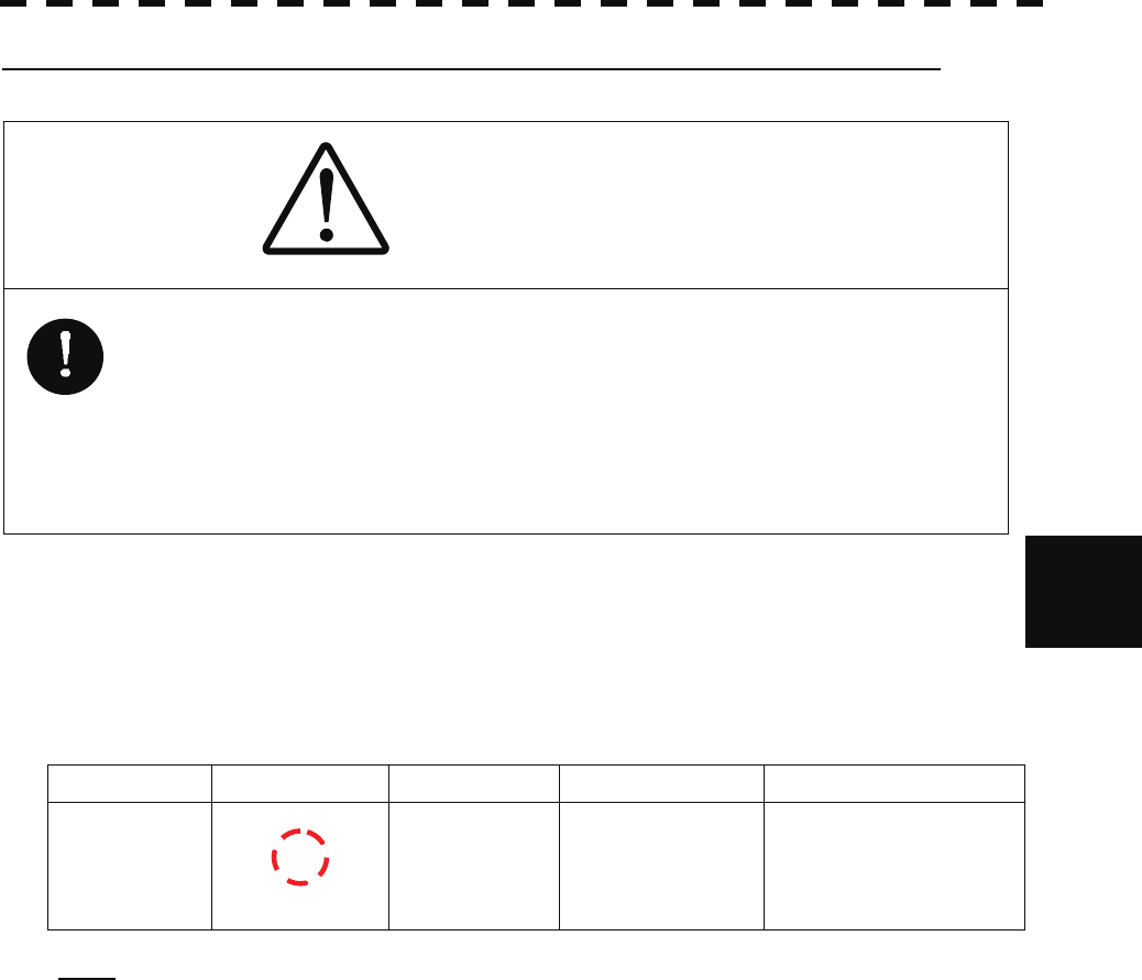
5-46
5.5 Alarm Display yy
yyy
5
Alarm for New Target Acquired in Automatic Acquisition Zone (New Target)
CAUTION
In setting an automatic acquisition zone, it is necessary to
adjust the gain, sea clutter suppression and rain clutter
suppression to ensure that target echoes are displayed in
the optimum conditions. No automatic acquisition zone
alarms will be issued for targets undetected by the radar,
and this may cause accidents such as collisions.
The automatic acquisition function sets a zone in a range and issues an alarm when a new target (which is
not yet acquired) goes into this zone.
For the setting of an automatic acquisition zone, refer to " Acquiring Target " in Section 5.2.1.
Alarm for New Target Acquired in Automatic Acquisition Zone
Status Symbol on display Alarm characters Alarm sound Conditions
New target in
automatic
acquisition
zone
Red Blinking
New Target Beep sound (pipi-pipi)
Alarm
acknowledgeable
The alarm is issued when a
new target is acquired in
the automatic acquisition
zone.
Note: When an already acquired target goes into automatic acquisition zone, the alarm message
is not displayed and the buzzer does not sound either.
12
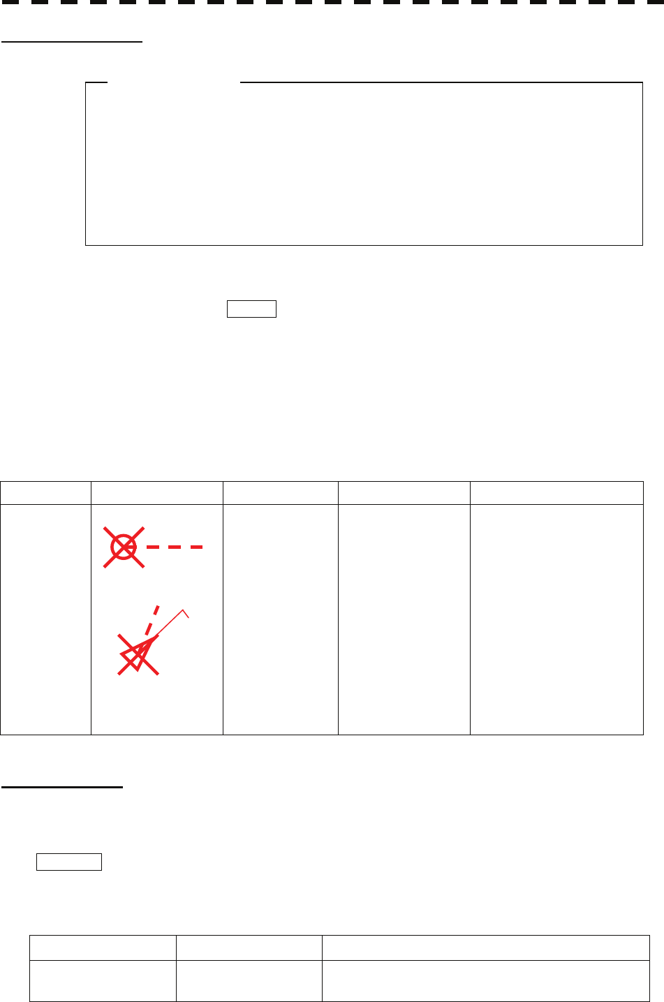
5-47
z If the gain, sea clutter suppression, rain/snow clutter
suppression are not adjusted adequately, the lost
target alarm may be easily generated. So such
adjustments should be mad carefully.
Lost Target Alarm
When it is impossible to continue tracking any acquired and tracked target, or the data of AIS target cannot
received for a specified time, the LOST alarm will be generated. The typical causes for alarm
generation are shown below, but not limited to the following:
• The target echo is very weak.
• The target is shadowed by a shore or a large ship and its echo is not received.
• The target echo is blurred by sea clutter returns.
If a target under tracking goes out of a range of 32 nm and can no longer be tracked, it is canceled without a
lost target alarm.
Lost Target Alarm
Status Symbol on display Alarm characters Alarm sound Conditions
Lost target
Red Blinking
Lost
Beep sound (pee)
Alarm
acknowledgeable
The alarm will sound once
when a lost target symbol is
displayed.
Gyro Set Alarm
The GYRO I/F in this system receives signals from a gyro. Even if the power is turned off, the system will
follow up the gyro. However, the system stops the follow-up operation when the power of the master gyro
is turned off or when any trouble occurs to the line. When the power of the master gyro is recovered, the
Set Gyro alarm will be generated.
If this alarm occurs, set the gyro.
Gyro Set Alarm
Alarm characters Alarm sound Conditions
Set Gyro Beep sound (pipi-pipi) The signals from the gyro are stopped, but the gyro is
recovered.
Attention
12
AIS12

5-48
5.6 Track Function yy
yyy
5
5.6 TRACK FUNCTION
5.6.1 Past Position (Past POSN)
Procedures 1 Put the cursor on the past position display interval unit switching
(TT/AIS information ⑦ on page 2-23), and press the [ENT] key to set
a desired unit.
The past position display interval unit will be set to min or NM .
2 Put the cursor on the past position display interval switching (TT/AIS
information ⑥ on page 2-23), and press the [ENT] key to set a desired
track display interval.
The past position will be set.
Off :Tracks are not displayed.
Numeric :Tracks are displayed at intervals of a specified value.
The past position function can display up to 10 past positions of a target under tracking. The past position
display interval can be set to specified time intervals of 0.5, 1, 2, or 4 minutes, or specified range intervals
of 0.1, 0.2, 0.5, or 1 nm.
The specified interval is displayed in the past position display interval switching (TT / AIS information ⑥
on page 2-23). When Off is displayed, the track display function is turned off.
The track mode operates in conjunction with the vector mode, and a true or relative track is displayed.
In relative vector mode, the relative tracks of the target are displayed.
In true vector mode, true tracks that are calculated from the relative bearing, range, own ship's course, and
speed are displayed.
The target is acquisition, past position of traced target is start plot.
The AIS target is displayed, past position of AIS target is start plot.
If the past position plotted time is short, the indicated past position duration may not have achieved the
specified time or range.

5-49
5.6.2 Target Ship's Tracks (Target Track)
This function makes settings for the tracks of tracked targets and AIS targets.
The system can display the tracks of up to 20 target ships.
[I] Track Color Setting (Target Track Color)
Procedures 1 Put the cursor on the tracked target or activated AIS target, and
press the [CLR / INFO] key.
The setting items for cursor modes will be displayed.
2 Press the [8] key.
The TT Target Information will appear.
3 Press the [2] key.
The setting items for Track Color will be displayed.
4 Press the [numeric] key corresponding to the track color to be set.
Colors set by performing the procedure in [III] Setting of Target Ship's Track Colors
can be selected.
Individual colors can be set for up to 10 ships.
The same color is set for 11 to 20 ships.
[II] Target Ship's Track Function On/Off (Target Track Function)
Procedures 1 Open the T.TRK menu by performing the following menu operation.
T.TRK
2 Press the [1] key.
The Target Track Function will be set to on or off.
On : Target Track Function is turned on.
Off : Target Track Function is turned off.
* Note that when this function is turned off, all the other ship's track functions are turned off. In this case,
the track data of other ships is not saved, so they cannot be traced later.
5-50
5.6 Track Function yy
yyy
5
[III] Setting of Target Ship's Track Colors (Target Track Color)
You can set either one track color for all targets under tracking, or individual colors for the ships of track
numbers 1 to 10. The tracks of ships 11 to 20 are displayed in the same color.
* If the other ship's track function (Target Track Function) is turned off, the track data of other ships is not
saved.
Procedures 1 Open the Target Track Color menu by performing the following menu
operation.
T.TRK
→ 2. Target Track Color
2 Press the [1] key.
The setting items for All will be displayed.
3 Press the [numeric] key corresponding to the track display to be set.
Individual : Track color is set individually for ships.
Color name : One color is set for all ships.
Individual setting
4 Press the [numeric] key corresponding to the track number to be set.
The setting items for the selected track number will be displayed.
5 Press the [numeric] key corresponding to the track color to be set.
The track color of the selected track number will be set.
When Individual is selected, the track numbers Target Track No. 1 to No. 10 and the individual
setting for Other are valid. Select a color for each target.
The color list is displayed by pressing the [numeric] key corresponding to the item number to be set.
Select a desired color. There are 8 color choices: Off , White , Cyan , Blue , Green , Yellow ,
Pink , and Red .
Target Track No. 1 to No. 10 : Setting for 1 to 10 ships
Other : Setting for 11 to 20 ships
* Note that the individual setting is not enabled unless Individual is selected.
5-51
[IV] Setting of Target Ship's Track Display (Target Track Display)
The target track display function can be turned on / off. Choices for track display are displaying / hiding
the tracks of all ships and Individual (displaying the tracks of individual ships).
Procedures 1 Open the Target Track Display menu by performing the following
menu operation.
T.TRK
→ 3. Target Track Display
2 Press the [1] key.
The setting items for All will be displayed.
3 Press the [numeric] key corresponding to the track display to be set.
Individual : Track display is set for individual ships.
Off : The tracks of all ships are hidden.
On : The tracks of all ships are displayed.
* Even when Target Track Display is turned off, the track data of other ships is saved if Track Memory
Interval is set.
Individual setting
4 Press the [numeric] key corresponding to the track number to be set.
The selected track number display will be set to on or off.
On :The track number display is turned on.
Off :The track number display is turned off.
When Individual is selected, the track numbers Target Track No. 1 to No. 10 and the individual
setting for Other are valid. Select on / off for each target.
Target Track No. 1 to No. 10 : Setting for 1 to 10 ships
Other : Setting for 11 to 20 ships
* Note that the individual setting is not enabled unless Individual is selected.

5-52
5.6 Track Function yy
yyy
5
[V] Setting of Target Ship's Track Saving Interval (Track Memory Interval)
An interval for saving target ship's track data can be set.
* This function is not available when the Target Track Function is turned off.
Procedures 1 Open the T.TRK menu by performing the following menu operation.
T.TRK
2 Press the [4] key.
The setting items for Track Memory Interval will be displayed.
3 Press the [numeric] key corresponding to the interval to be set.
Select an interval from the following:
Off /
3 sec / 5 sec / 10 sec / 30 sec /
1 min / 3 min / 5 min / 10 min / 30 min / 60 min /
1 NM / 3 NM / 5 NM / 10 NM
5-53
[VI] Clear of Target Ship's Track
The target ship's track can be cleared by setting a color or a track number.
* If Card T.TRK Display is used, target ship's tracks displayed through the card cannot be cleared.
Clear of Tracks by Setting Color (Clear Track Color)
Procedures 1 Open the T.TRK menu by performing the following menu operation.
T.TRK
2 Press the [5] key.
The setting items for Clear Track Color will be displayed.
3 Press the [numeric] key corresponding to the color of the target
tracks to be cleared.
The Confirmation Window will appear.
4 Press the [1] key.
All the tracks of the selected color will be cleared.
Clear of Tracks by Setting Track Number (Clear Track Number)
Procedures 1 Open the T.TRK menu by performing the following menu operation.
T.TRK
2 Press the [6] key.
The setting items for Clear Track Number will be displayed.
3 Press the [numeric] key corresponding to the number of the tracks to
be cleared.
The Confirmation Window will appear.
4 Press the [1] key.
The tracks of the selected number will be cleared.

5-54
5.6 Track Function yy
yyy
5
[VII] Operation of Target Ship's Track Data Saved on Card (File Operations)
Target ship's track data can be saved on a flash memory card and read from the card.
Note: Data can be saved to a flash memory card until the card becomes full, but the number of files that
can be read and displayed is limited to 64 in alphanumeric order. When the number of files has
reached 64, delete unnecessary files.
Loading File (Load)
Procedures 1 Insert a flash memory card into the card slot
For the insertion and removal of the card, see HOW TO INSERT AND REMOVE A
CARD in the appendix.
2 Open the File Operations menu by performing the following menu
operation.
T.TRK
→ 7. File Operations
3 Press the [1] key and select a card slot.
The setting item for Select Card Slot is switched between Slot1 and Slot2.
4 Press the [2] key and select Add or Overwrite.
The setting item for Load Mode is switched between Add and Overwrite.
When Add is selected, new data is added to the current data on the card. When
Overwrite is selected, new data is saved over the current data on the card.
5 Press the [3] key.
Currently saved target ship's track data on the card will be listed.
6 Press the [numeric] key corresponding to the file to be loaded.
The Confirmation Window will appear.
7 Press the [1] key.
The selected target track data will be loaded and shown on the radar display.

5-55
Saving File (Save)
Procedures 1 Insert a flash memory card into the card slot.
For the insertion and removal of the card, see HOW TO INSERT AND REMOVE A
CARD in the appendix.
2 Open the File Operations menu by performing the following menu
operation.
T.TRK
→ 7. File Operations
3 Press the [1] key and select a card slot.
The setting item for Select Card Slot is switched between Slot1 and Slot2.
4 Press the [4] key.
The Save menu will appear.
5 Input the file name to be saved.
Up to 10 characters can be input as a file name.
For inputs to the characters input screen, refer to Section 3.3.4.
After the input, the Confirmation Window will appear.
6 Press the [1] key.
The currently displayed target track data will be saved.
5-56
5.6 Track Function yy
yyy
5
Erasing File (Erase)
Procedures 1 Insert the flash memory card into the card slot.
For the insertion and removal of the card, see HOW TO INSERT AND REMOVE A
CARD in the appendix.
2 Open the File Operations menu by performing the following menu
operation.
T.TRK
→ 7. File Operations
3 Press the [1] key and select a card slot.
The setting item for Select Card Slot is switched between Slot1 and Slot2.
4 Press the [5] key.
The Erase menu will appear.
Currently saved target ship's track data on the card will be listed.
5 Press the [numeric] key corresponding to the file to be erased.
The Confirmation Window will appear.
6 Press the [1] key.
The selected target track data will be erased and the file name will disappear from the
list.

5-57
Displaying File (Card Target Track Display)
Procedures 1 Insert the flash memory card into the card slot.
For the insertion and removal of the card, see HOW TO INSERT AND REMOVE A
CARD in the appendix.
2 Open the File Operations menu by performing the following menu
operation.
T.TRK
→ 7. File Operations
3 Press the [1] key and select a card slot.
The setting item for Select Card Slot is switched between Slot1 and Slot2.
4 Press the [6] key.
The Card T.TRK Display menu will appear.
Currently saved target ship's track data on the card will be listed.
5 Press the [numeric] key corresponding to the file to be displayed.
The Confirmation Window will appear.
6 Press the [1] key.
The selected file will be highlighted, and the currently saved target track data will be
displayed.
Cancellation 1 Open the Card T.TRK Display window.
The displayed file is highlighted.
2 Press the [numeric] key corresponding to the displayed file.
The Confirmation Window will appear.
3 Press the [1] key.
The file will be deselected and returned to normal display.

5-58
5.7 Trial Maneuvering yy
yyy
5
z Trial maneuvering is to simulate own ship’s course and
speed in the conditions that the course and speed of a
target ship are unchanged as they are. As the
situation is different from any actual ship
maneuvering, set values with large margins to CPA
Limit and TCPA Limit.
5.7 TRIAL MANEUVERING
(TRIAL MANEUVER)
The trial maneuvering is the function of simulating own ship’s course and speed for collision avoidance
when a dangerous target appears. When the own ship's course and speed are entered in manual mode, the
trial maneuvering function checks if pre-acquired or pre-activated targets are dangerous.
The ranges of course and speed to be entered manually:
Course: 360 ° (in 0.1 ° intervals) .........................................................................[EBL] dial
Speed: 0 to 100 kn (in 0.1 kn steps) ...................................................................[VRM] dial
Attention
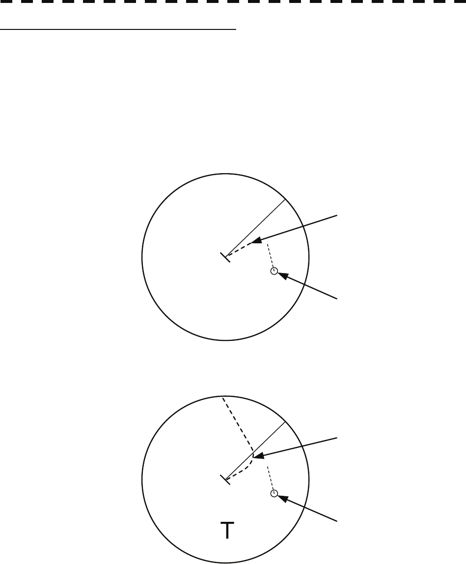
5-59
Trial Maneuvering in the True Vector Mode
In the True Vector mode, calculations are performed according to the values set by Trial Speed, Trial Course
and other features, and the result is displayed as a bold-line that represents the change of own ship’s vector
as shown in the figure below (an example of the course changed to the right).
In this figure, the dangerous target forward left becomes safe as a result of simulation.
The tracked target information indicates the current CPA and TCPA values regardless of the result of
simulation.
Dangerous target
HL
Change of symbol
as a result of
trial maneuver
HL
TRIAL
NORMAL
Route
Own ship’s vector
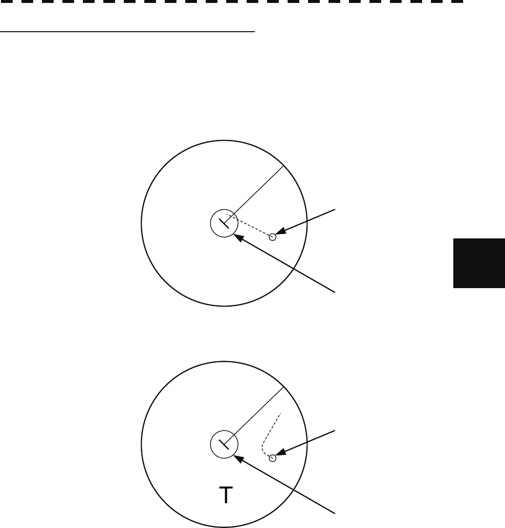
5-60
5.7 Trial Maneuvering yy
yyy
5
Trial Maneuvering in the Relative Vector Mode
The result of Trial maneuvering in the Relative Vector mode is shown by a change in target vector. In the
figure below (in the same conditions as in the True Vector mode in the previous page), it is seen that the
acquired target is a dangerous one because its vector is crossing the CPA RING.
CPA Ring
Change of symbol
as a result of
trial maneuver
TRIAL
NORMAL
Dangerous target
CPA Ring
HL
HL
The above figure shows that the relative vector of the target has changed as shown in the figure as a result
of simulation (course and speed), so that the symbol color is changed into “White”, a safe target.
Irrespective of the simulation results, the current CPA and TCPA values are shown in the tracked target
information just like when the true vector mode is active.
The course change of own ship is displayed as a dotted-line.
Better information is provided by using relative motion and sea stabilization.
5-61
Operation of Trial Maneuvering Function
Procedures 1 Press the [TT MENU] key.
2 Open the Trial Maneuver menu by performing the following menu
operation.
3. Trial Maneuver
3 Press the [1] key.
The Trial Function will be set to on or off.
On : The trial maneuvering function is turned on.
Off : The trial maneuvering function is turned off.
When the Trial Function is active, the character " T " will display at the bottom of the
radar display.
4 Set values for Course by turning the [EBL] dial, and for Speed by
turning the [VRM] dial.
5 Set other characteristics.
Vector Time : Vector time (1 to 60 min)
Time to Maneuver : Time until trial maneuvering is started (0 to 30 min)
Own Ship Dynamic Trait> : Dynamic trait of the own ship
→ Reach : Range from when steered to when the ship
beings to turn (0 to 2000 m)
→ Turn Radius : Turning radius (0.10 to 2.00 NM)
→ Acceleration : Acceleration (0.0 to 100 kn/min)
→ Deceleration : Deceleration (0.0 to 100 kn/min)
For inputs to the value input screen, refer to Section 3.3.4.
Dangerous target symbols are displayed in red and safe target symbols in white.
* Vector Time is valid only when Trial Function is set to on. If it is off, the vector time before trial
maneuvering is displayed.
Time until the start of trial maneuvering is counted down immediately after the input.
The acceleration and deceleration are influenced depending on the relationship between the current
speed and the input speed for trial maneuvering.
If 0.0 kn/min is set for Acceleration when the speed for trial maneuvering is faster than the current
speed, or for Deceleration when the speed for trial maneuvering is slower than the current speed, the
system performs simulation on the assumption that the speed is changed immediately after the time set
for Time to Maneuver .
Cancellation 1 Press the [1] key while the Trial Maneuver menu is displayed.
The Trial Function will be set to on or off.
Off : The trial maneuvering function is turned off.

5-62
5
5
5.8 EPA Operation yy
yyy
5.8 EPA OPERATION
This section explains how to use the EPA function.
The EPA function is available when a target tracking unit (option) is not connected.
The EPA function saves/displays vectors as the courses and speeds of target ships.
The data of up to 10 target ships (plot/ID numbers 0-9) can be specified.
The EPA function calculates CPA/TCPA, and issues an alarm.
The data of plotted target ships is erased from memory when the power is turned off or transmission standby
state.
The EPA function does not display any past plot data.
The past position function is not available.
The EPA function does not calculate BCR or BCT.
The target ID name function is not available.
The automatic acquisition function is not available. (The radar alarm is available.)
The Target Track Function is not available.
The reference target function is not available.
The Trial Maneuver is not available.
* The setting procedure for target tracking applies to the following:
1. Vector Time
2. CPA Limit
3. TCPA Limit
4. CPA Ring
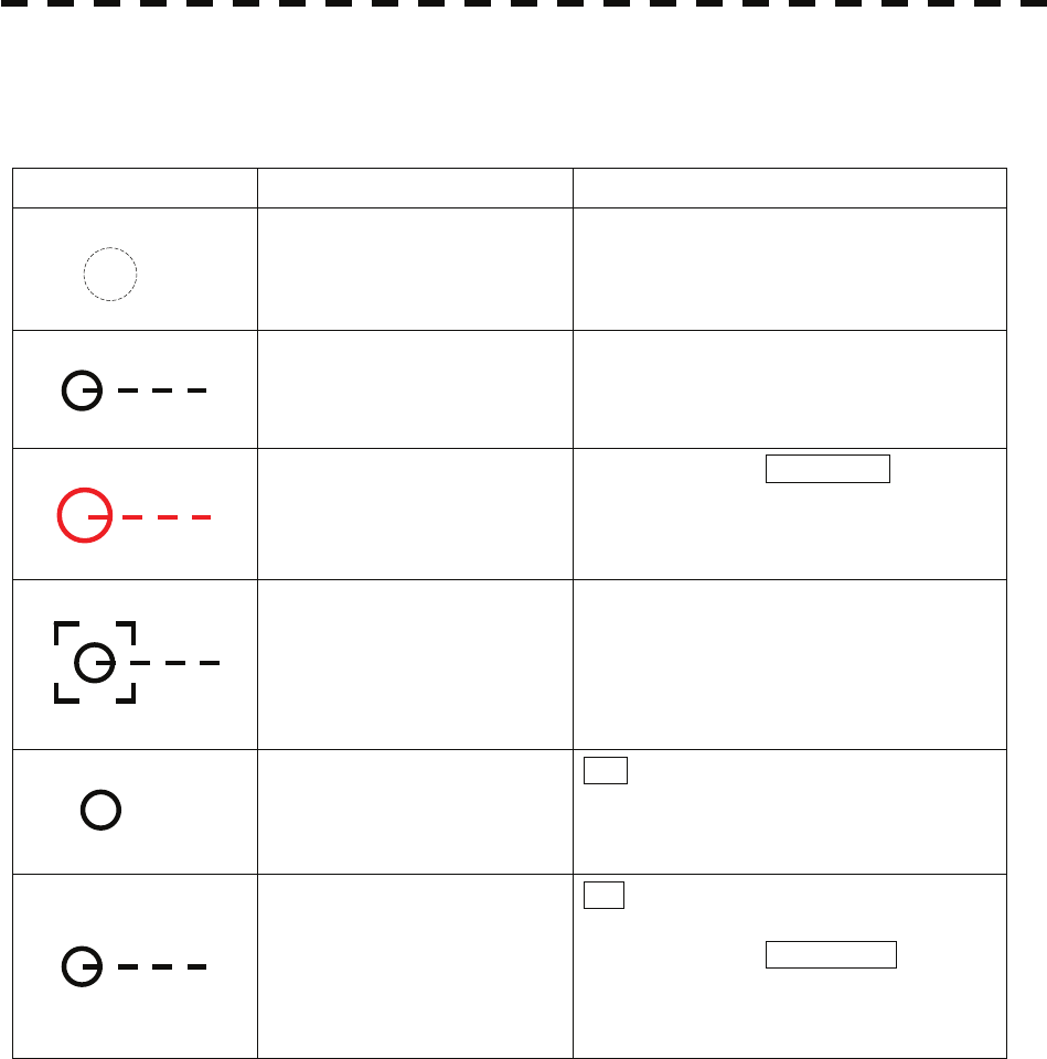
5-63
5.8.1 Definitions of Symbols
Types and Definitions of EPA Symbol
Vector/Symbol Definition Remarks
Initial plot
This symbol is displayed when the first
plotting is performed.
The symbol is displayed until the vector is
displayed after the second plotting.
Plot vector
Dangerous plot vector
The alarm message CPA/TCPA is
displayed
The alarm sounds.
The symbol blinks red.
Numeric displayed plot vector When the numeric data is displayed, the
symbol is enclosed in a square.
Plot data modification
M is displayed beside the plot data
modification symbol.
It is displayed at the previous plotting
position.
Plot data update request
U is displayed when the plot data is not
updated for 10 minutes.
The alarm message Update EPA is
displayed and the alarm sounds once.
If the plot data is not updated within 5
minutes after the alarm, it is erased.
3U
3M
3
3
3
3

5-64
5
5
5.8 EPA Operation yy
yyy
5.8.2 Plotting Targets
Vectors are displayed when a target is plotted twice.
A course and speed are calculated from the two plotting positions, and the plotted target moves in the course
at the speed.
The plot can be modified.
The target ID number is not displayed while Display ID Number is set to off.
Procedures 1 Put the cursor on the target, and press the [ACQ] key to start the first
plotting.
2 Enter the plot number (target ID number), pressing [0] to [9].
3. Press [ENT] to finish the first plotting.
The symbol and plot number will be displayed at the plotting position.
4 When 30 seconds to 15 minutes has passed after the first plot, Put the
cursor on the current target position, and take steps 1 to 3 to perform
the second plotting.
When finishing the second plotting, the system clears the symbol and plot number that
were displayed at the end of the first plotting, and displays the symbol (vector) and
plot number at the second plotting position.
The plotted target (symbol and plot ID number) moves in a specified course at a
specified speed. The course and speed are calculated from the two plotting positions.
At this time, the CPA and TCPA at positions where the plotted target moves are
calculated, and an alarm is issued when the plotted target goes into the dangerous
judgment.
5.8.3 Modifying Plotted Target Data
The system modifies specified plotted target data.
It clears the specified data, and displays the plotted target immediately before it moves to the clear position
until re-acquiring a target.
Procedures 1 Press the [ACQ] key.
2 Enter the plot number (target ID number) for modification, pressing [0]
to [9].
3 Press the [CLR / INFO] key.
The previously updated status will be displayed. M is also displayed beside the
mark, indicating that modification is in progress.
4 Put the cursor on the modification position to re-acquire a target, and
plotting.
At this time, specify the plot number you entered in step 2.
([ACQ], [0]-[9], [ENT])

5-65
5.8.4 Canceling Plotted Target Data
The system cancels the display of specified plotted target data.
Once plotted target data is canceled, it cannot be re-saved any more.
Procedures 1 Press the [ACQ] key.
2 Enter the plot number for cancellation, pressing [0] to [9].
3 Press the [TGT CNCL] key.
The plotted target data of the specified plot number will be canceled.
Canceling all plotted targets
Procedures 1 Press the [TGT CNCL] key for 5 seconds or more.
The plotted targets of all the plot numbers will be canceled.
5.8.5 Displaying Numeric Data of Plotted Targets
The following data is displayed for a specified plotted target:
TGT ID Plot number
BRG Bearing :0.1° unit
Range Range :0.01 nm unit
Course Target’s true course :0.1° unit
Speed Target’s true speed :0.1 kn unit
CPA CPA :0.01 nm unit
TCPA TCPA :0.1 min unit
TIME Elapsed time :0.1 min unit
Procedures 1 Press the [TGT DATA] key.
2 Enter the plot number pressing [0] to [9].
3 Press the [ENT] key.
The data of the specified plot number will be displayed.
The mark of the target for which numeric data is displayed is changed into “ ”.

SECTION 6
TRUE AND FALSE ECHOES ON DISPLAY
6.1 RADAR WAVE WITH THE HORIZON .................................................6-1
6.2 STRENGTH OF REFLECTION FROM THE TARGET.........................6-3
6.3 SEA CLUTTER AND RAIN AND SNOW CLUTTER............................6-5
6.4 FALSE ECHOES..................................................................................6-9
6.5 DISPLAY OF RADAR TRANSPONDER (SART)...............................6-12
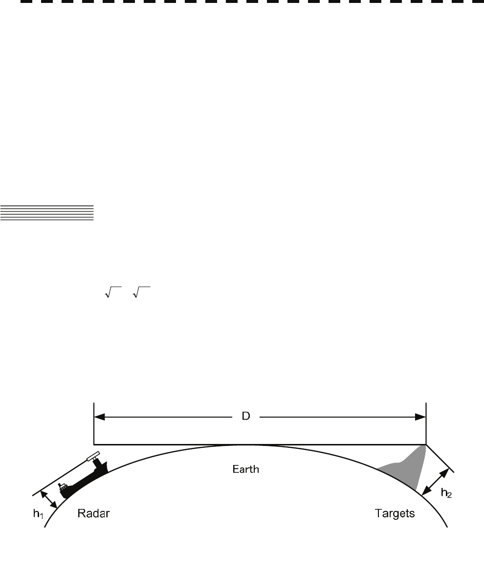
6-1
The radar operator has a role of interpreting the radar displays to provide his best aid in maneuvering the
ship. For this purpose, the operator has to observe the radar displays after fully understanding the
advantages and disadvantages that the radar has. For better interpretation of radar display, it is important
to gain more experiences by operating the radar equipment in fair weathers and comparing the target ships
watched with the naked eyes and their echoes on the radar display.
The radar is mainly used to monitor the courses of own ship and other ships in open seas, to check buoys
and other nautical marks when entering a port, to measure own ship’s position in the coastal waters relative
to the bearings and ranges of the shore or islands using a chart, and to monitor the position and movement
of a heavy rain if it appears on the radar display.
Various types of radar display will be explained below.
6.1 RADAR WAVE WITH THE HORIZON
Radar beam radiation has the nature of propagating nearly along the curved surface of the earth.
The propagation varies with the property of the air layer through which the radar beam propagates.
In the normal propagation, the distance (D) of the radar wave to the horizon is approximately 10% longer
than the distance to the optical horizon. The distance (D) is given by the following formula:
D=2.23( h2h1 +)(nm)
h1: Height (m) of radar scanner above sea level
h2: Height (m) of a target above sea level
Figure 6.1 is a diagram for determining the maximum detection range of a target that is limited by the curve
of the earth surface in the normal propagation.
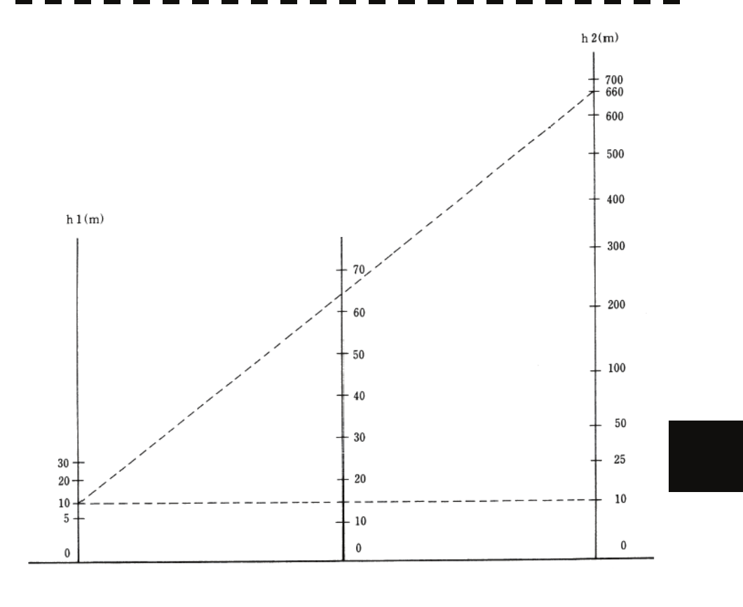
6-2
6.1 Radar Wave with the Horizon
y
yy
yyy
6
Figure 6.1
When the height of own ship’s scanner is 10 m for instance,
(a) A target that can be detected at the radar range of 64 nm on the radar display is required to have a
height of 660 m or more.
(b) If the height of a target is 10 m, the radar range has to be approx. 15 nm. However, the maximum
radar range at which a target can be detected on the radar display depends upon the size of the target
and the weather conditions, that is, the radar range may increase or decrease depending upon those
conditions.
Height of Radar Scanne
r
Detective Range Height of Target
D (nm)
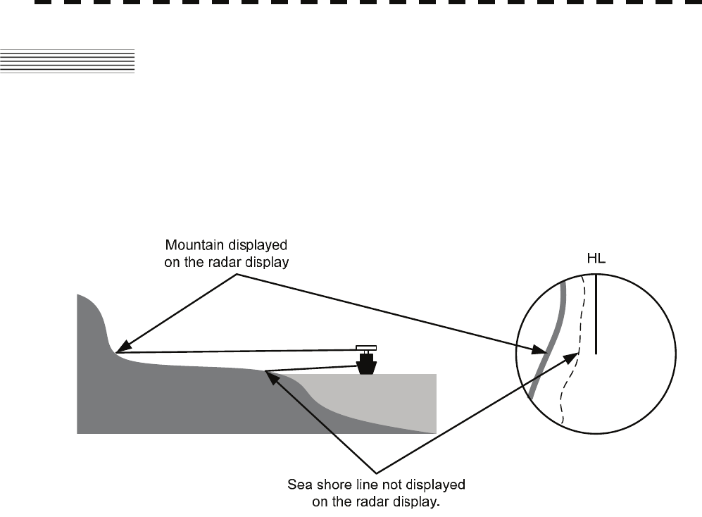
6-3
6.2 STRENGTH OF REFLECTION FROM
THE TARGET
The signal intensity reflected from a target depends not only on the height and size of the target but also on
its material and shape. The echo intensity from a higher and larger target is not always higher in general.
In particular, the echo from a coast line is affected by the geographic conditions of the coast.
If the coast has a very gentle slop, the echo from a mountain of the inland appears on the radar display.
Therefore, the distance to the coast line should be measured carefully.
Figure 6.2
Table 6.1 shows the graph indicating the relation between the target detection distance and the radar
reflection cross-sectional area (RCS) with regard to the type and the height of the target in a situation in
which the weather is good, the sea state is calm and the radio wave propagation is normal. As revealed by
this table, even on the same sea shore line, detection distance greatly differs depending on the height of the
target from the surface of the sea. Furthermore, because the target detection distance is greatly influenced
by the shape and material of the target and environmental conditions, such as the sea state, weather, and
radio wave propagation, caution should be taken when detecting distance of target.

6-4
y
yy
yyy
6
Table 6.1 Relation between type and height of target and detection distance and RCS
Caution: Detection distance shown in the above table may greatly decrease depending on the shape of
the target, sea state, weather and radio wave propagation conditions.
Detection distance (NM) RCS (m²)
Type of target Height from
sea surface
(m) X band S band X band S band
Sea shore line 60 20 20 50,000 50,000
Sea shore line 6 8 8 5000 5000
Sea shore line 3 6 6 2500 2500
SOLAS target ship (>5000GT) 10 11 11 50,000 30,000
SOLAS target ship (>500GT) 5 8 8 1800 1000
Small boat with IMO standard
compatible radar reflector 4 5.0 3.7 7.5 0.5
Marine buoy with corner reflector 3.5 4.9 3.6 10 1
Standard marine buoy 3.5 4.6 3.0 5 0.5
10-meter small boat without radar
reflector 2 3.4 3.0 2.5 1.4
Waterway location beacon 1 2.0 1.0 1 0.1
6.2 Stren
g
th of Reflection from the Tar
g
et
6-5
6.3 SEA CLUTTER AND RAIN AND SNOW
CLUTTER
In addition to the echo required for observing ships and land radar video image also includes unnecessary
echo, such as reflection from waves on the sea surface and reflection from rain and snow. Reflection from
the sea surface is called "sea clutter," and reflection from rain and snow is called "rain and snow clutter,"
and those spurious waves must be eliminated by the clutter rejection function.
[I] Sea clutter
Sea clutter appears as an image radiating outwardly from the center of the radar display and changing
depending on the size and the shape of waves. Generally, as waves become larger, image level of the
sea clutter is intensified and the clutter far away is also displayed. When waves are large and the sea
clutter level is high, it is difficult to distinguish sea clutter from a small boat whose reflection intensity
is weak. Accordingly, it is necessary to properly adjust the sea clutter rejection function. Table 6.2
shows the relation between the sea state (SS) showing the size of waves generated by wind and the
radar's detection probability.
Table 6.2 Sea state and probability of target detection
S band radar (probability to detect a target at a distance of 0.4 NM)
X band radar (probability to detect a target at a distance of 0.7 NM)
V: Detection probability of 80 %
M: Detection probability of 50 %
NV: Detection probability of less than 50 %
RCS SS1 to 2 SS2 to 3 SS3 to 4 SS4 to 5
0.1m2 V V-M M-NV
0.5 m2 V V V-M M-NV
1 m2 V V V V-M
RCS SS1 to 2 SS2 to 3 SS3 to 4 SS4 to 5
1m2 V-M M-NV
5 m2 V V-M M-NV
10 m2 V V V V-M

6-6
y
yy
yyy
6
As shown in Table 6.3, the number of SS increases as the wind speed becomes high and the waves
become large. Table 6.2 reveals that detection probability decreases from V (80 %) to NV (less than
50 %) as the number of SS increases. Therefore, even if the sea state is calm and a target clearly
appears on the radar display, when the sea state becomes rough, target detection probability decreases
resulting in difficulty of target detection by the radar.
Table 6.3 Relation between Douglas sea state and average wind speed and significant wave
height
Significant wave height: an average of top N/3 higher waves when the
number of waves detected within a constant time
duration is N
For example, in the case of a standard marine buoy, RCS of X band radar is 5 m2 as shown in Table 6.1.
When observing such a target in the sea state (SS3) in which significant wave height exceeds 1.2
meters, detection probability is M-NV, as shown in Table 6.2, which indicates 50 % or less.
[II] Rain and snow clutter
Rain and snow clutter is a video image that appears in a location where rain or snow is falling. The
image changes according to the amount of rain (or the amount of snowfall). As precipitation
increases, the image of rain and snow clutter becomes intensified on the radar display, and in the case
of localized heavy rain, an image similar to the image indicating land is displayed in some cases.
Furthermore, because radio waves tend to attenuate due to rain and snow, the ability to detect a target
in the rain and snow clutter or a target beyond the rain and snow clutter may decrease. The amount of
attenuation depends on the transmission frequency, antenna beam width, and the pulse length. Figure
6.3 and Figure 6.4 show examples in which detection distance is reduced due to the influence of
precipitation. Because of this, a target, which clearly appeared up to 10 NM by an X band radar
(pulse width of 0.8 μs) when it was not raining, may become dimly visible up to 5 NM when the
amount of rain becomes 4 millimeters per hour. Furthermore, when comparing the X band radar with
the S band radar, target detection distance decreases less when an S band radar is used, which means it
is influenced less by precipitation.
Sea state Average wind speed (kn) Significant wave height (m)
0 <4 <0.2
1 5-7 0.6
2 7-11 0.9
3 12-16 1.2
4 17-19 2.0
5 20-25 3.0
6 26-33 4.0
6.3 Sea Clutter and Rain and Snow Clutte
r
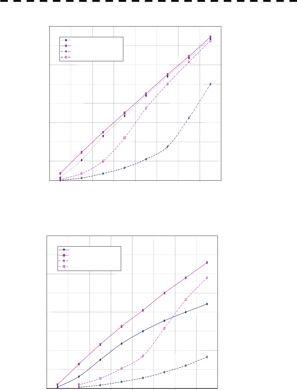
6-7
Figure 6.3 Decreased target detection distance by S band radar due to precipitation
Figure 6.4 Decreased target detection distance by X band radar due to precipitation
0
2
4
6
8
10
12
14
16
0 2 4 6 8 10 12 14 16
Detection distance while it is raining (NM)
Precipitation of 16 mm/hr Pulse width 0.05 μs
Precipitation of 4 mm/hr Pulse width 0.05 μs
Precipitation of 16 mm/hr Pulse width 0.8 μs
Precipitation of 4 mm/hr Pulse width 0.8 μs
Detection distance while it is not raining (NM)
02468 1 12 14 16
Detection distance while it is not raining (NM)
Precipitation of 16 mm/hr Pulse width 0.05 μs
Precipitation of 4 mm/hr Pulse width 0.05 μs
Precipitation of 16 mm/hr Pulse width 0.8 μs
Precipitation of 4 mm/hr Pulse width 0.8 μs
Detection distance while it is raining (NM)
0
2
4
6
8
10
12
14
16
6-8
y
yy
yyy
6
[III] Coping with sea clutter and rain and snow clutter
When the weather is bad and the ocean is rough, the use of an S band radar is effective because the
radar is not influenced by sea clutter so much and attenuation due to rain drops is small. When an X
band radar is used, reducing the pulse width will reduce the influence by spurious waves, and also the
spurious wave rejection function effectively works; therefore, the use of short pulse is effective when
the weather is bad. By using image processing functions PROC 1 to 3, it is expected that spurious
waves are further suppressed. Since optimal settings for those items can be automatically made by
using the function mode, it is recommended that FUNC Storm or FUNC Rain be used by
selecting the function mode when the weather is bad. For details of the function mode, see Chapter
3.9.
However, these functions may make some targets invisible, particularly targets with higher speeds.
6.3 Sea Clutter and Rain and Snow Clutte
r
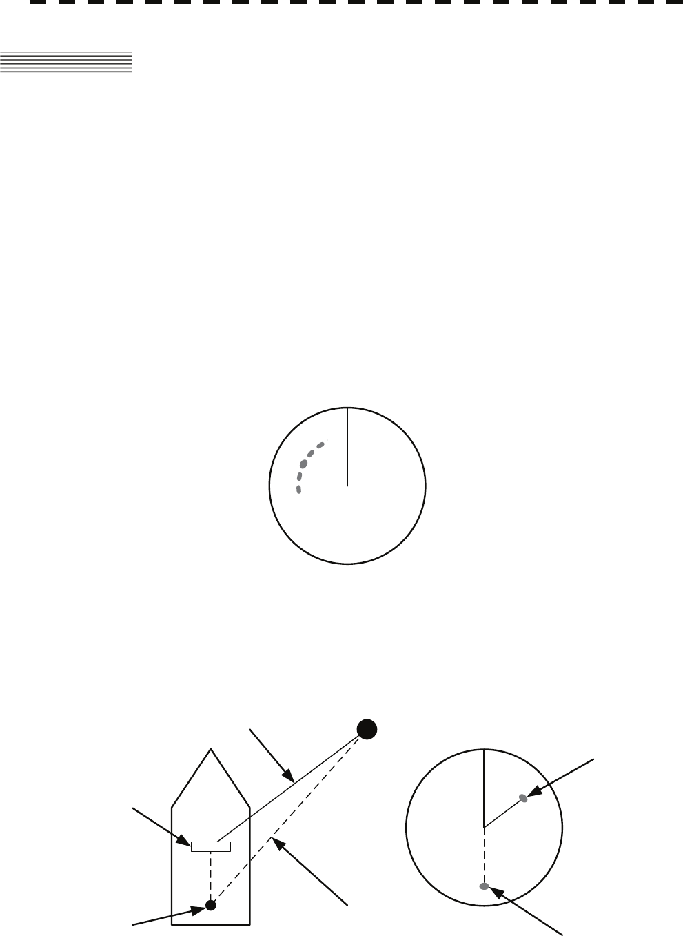
6-9
6.4 FALSE ECHOES
The radar observer may be embarrassed with some echoes that do not exist actually. These false echoes
appear by the following causes that are well known:
[I] Shadow
When the radar scanner is installed near a funnel or mast, the echo of a target that exists in the direction
of the funnel or mast cannot appear on the radar display because the radar beam is reflected on the
funnel or mast. Whether there are some false echoes due to shadows can be checked monitoring the
sea clutter returns, in which there may be a part of weak or no returns.
Such shadows appear always in the same directions, which the operator should have in mind in radar
operation.
[II] Side Lobe Effect
A broken-line circular arc may appear at the same range as the main lobe of the radar beam on the radar
display. This type of false echo can easily be discriminated when a target echo appears isolated.
(See Figure 6.5)
HL
Figure 6.5
[III] False Echo by Secondary Reflection
When a target exists near own ship, two echoes from the single target may appear on the radar display.
One of those echoes is the direct echo return from the target and the other is the secondary reflection
return from a mast or funnel that stands in the same direction as shown in Figure 6.6.
Radar
scanner
Funnel
HL
Direct microwave
Secondary reflection
of microwave
Actual target
False echo from funnel
Figure 6.6
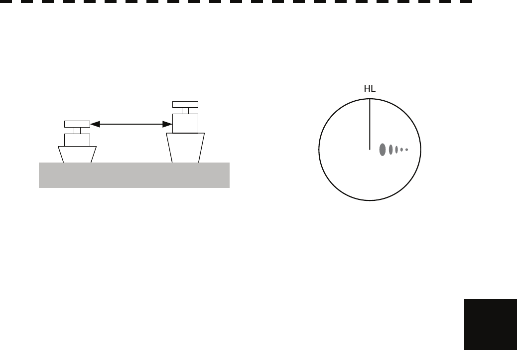
6-10
6.4 False Echoes
y
yy
yyy
6
[IV] False Echo by Multiple Reflection
When there is a large structure or ship with a high vertical surface near own ship as shown in Figure
6.7, multiple refection returns may appear on the radar display. These echoes appear in the same
intervals, of which the nearest echo is the true echo of the target.
Figure 6.7
[V] Second Time Echoes
The maximum radar detection range depends upon the height of the scanner and the height of a target
as described in the section of “The Horizon for Radar Beam Radiation”. If a so-called “duct” occurs
on the sea surface due to a certain weather condition, however, the radar beam may propagate to a
abnormally long distance, at which a target may be detected by the radar.
For instance, assuming that the pulse length is MP3 (on the repetition frequency of 1400 Hz), the first
pulse is reflected from a target at about 58 NM or more and received during the next pulse repetition
time. In this case, a false echo (second time echo) appears at a position that is about 58 NM shorter
than the actual distance. If the false echo appears at 5 NM on the radar display, the true distance of
the target is 5+58=63 NM. On the pulse length is SP1 (on the repetition frequency of 2250 Hz), a
false echo may appear at a position that is about 36 NM shorter than the actual distance.
This type of false echo can be discriminated by changing over the range scale (the repetition frequency),
because the distance of the target changes accordingly.
If second time echo is appeared, the use of Economy mode in PRF menu is effective. Otherwise,
Stagger Trigger menu set to on. (See section 3.8.3)
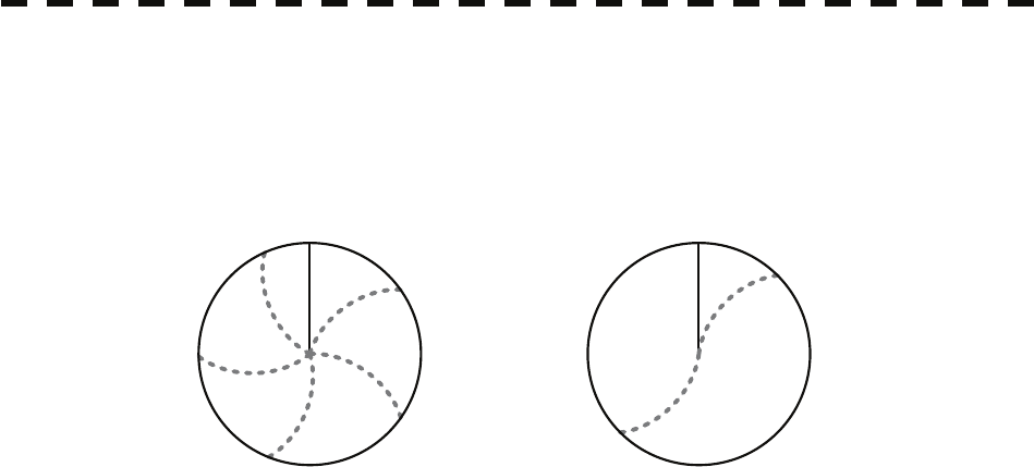
6-11
[VI] Radar Interference
When another radar equipment using the same frequency band as that on own ship is near own ship, a
radar interference pattern may appear on the radar display. This interference pattern consists of a
number of spots which appear in various forms. In many cases, these spots do not always appear at
the same places, so that they can be discriminated from the target echoes. (See Figure 6.8)
HL HL
Figure 6.8
If radar equipment causing an interference pattern and this radar are of the same model, their
transmitting repetition frequency is nearly the same. As a result, interference patterns may be
displayed concentrically.
In this case, the interference patterns cannot be eliminated by using only the interference reflector
function, so press [TX/PRF] key several times to fine-tune the transmitting repetition frequency.
An interference suppressing effect can be heightened by applying a different transmitting repetition
frequency to the interference pattern source radar and this radar.
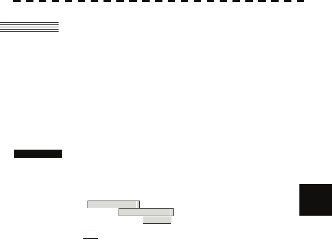
6-12
y
yy
yyy
6
6.5 DISPLAY OF RADAR TRANSPONDER
(SART)
The SART (Search and rescue Radar Transponder) is a survival device authorized by the GMDSS (Global
Maritime Distress and Safety System), which is used for locating survivors in case that a distress accident
occurs at sea. The SART is designed to operate in the 9 GHz frequency band.
When receiving the 9 GHz radar signal (interrogating signal) transmitted from the radar equipment on a
rescue ship or search aircraft, the SART transmit a series of response signals to inform the distress position
to the rescue and search party.
* This radar provides a shortcut item to make settings for SART signal reception. Execution of this item
automatically switches to the setting for SART reception.
It also functions for detect the beacon or target enhancer.
Procedures 1 Press [RANGE +] or [RANGE -] key to set the radar range to 6
NM or 12 NM.
2 Press [RADAR MENU] key twice, and then set the SART
display mode according to the procedures below.
2. RADAR Menu
→ 1. Process Setting
→ 9. SART
On : SART On
Off : SART Off
With the SART display mode set to ON, settings as shown below are made automatically.
(1) Sea clutter control: Minimum (Most counterclockwise)
(2) AUTO SEA function: Off
(3) Rain and Snow Clutter Control (RAIN): minimum
(4) Auto Rain and Snow Clutter function (AUTO RAIN): Off
(5) TUNE control: No tuning (to weaken clutter echoes)
(6) Interference rejecter (IR): Off
(7) PROCESS: Off
6.5 Displa
y
of Radar Transponde
r
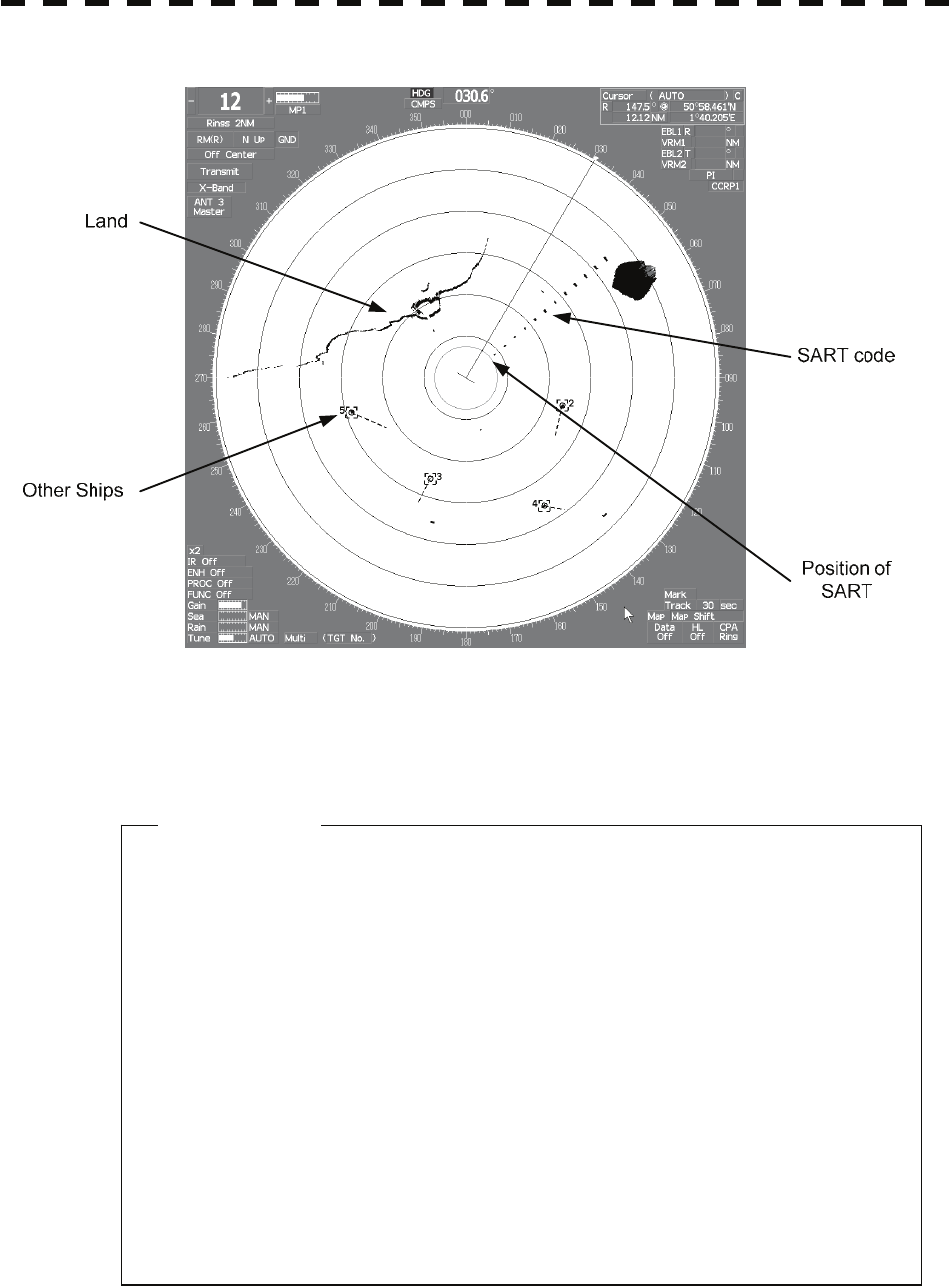
6-13
z When the SART function is set to ON, small targets around own
ship will disappear from the radar display. So it is necessary to
exercise full surveillance over the conditions around own ship
by visual watch in order to avoid any collision or stranding.
z If two or more sets of radar equipment are installed on own ship,
use one set of 9 GHz band radar for detection of the SART signal
and operate others as normal radars for avoiding collision,
monitoring targets around own ship, and checking on own
ship’s position and avoidance of stranding.
z After end of detecting the START signal, turn the START display
off. Then the radar returns normally to the nautical mode.
[Example of Display]
Attention

SECTION 7
SETTINGS FOR SYSTEM OPERATION
7.1 SETTINGS AT INSTALLATION ...........................................................7-1
7.2 SETTINGS..........................................................................................7-10
7.3 ADJUSTMENT...................................................................................7-22
7.4 MAINTENANCE MENU .....................................................................7-28
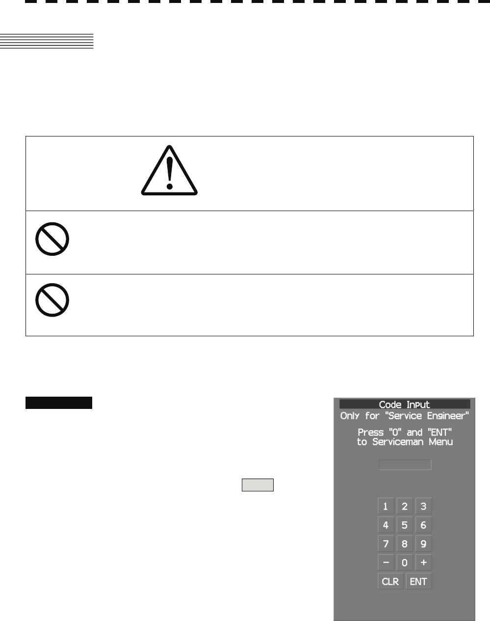
7-1
7.1 SETTINGS AT INSTALLATION
This section describes the electrical adjustment procedures to be performed by service engineers during
system installation.
The bearing adjustment value is saved to non-volatile memory in the scanner. Other settings are saviedto
non-volatile memory in the radar process unit.
CAUTION
Any adjustments must be made by specialized service
personnel.
Incorrect settings may result in unstable operation.
Do not make any adjustments during navigation. Failure
to comply may result in adverse effects on the radar
function which may lead to accidents or equipment failure.
7.1.1 How to Open the Serviceman Menu
Procedures 1. Press the [RADAR Menu] key for 2
seconds.
The Code Input menu will appear.
2. Press [0] key.
3. Put the cursor on the ENT button,
and press the [ENT] key.
The Serviceman Menu will appear.

7-2
7.1 Settings at Installation yyy
yyyy
7
7.1.2 GYRO I/F Setting
The GYRO I/F circuit of the system is designed to be compatible with most types of gyro compasses by
simply setting the switches.
Step motor type: 20 to 170 VDC
Synchro-motor type: Primary excitation voltage 35 to 120 VAC
Before power-on operation can be performed, the switches S1 to S5 on the GYRO I/F circuit (PC4201)
must be set in accordance with the type of your gyro compass by performing the procedure below. The
switches are factory-set for a gyration ratio of 180X and the step motor type. Make sure of the type of the
gyro compass installed on the own ship before starting the procedure below.
Procedures 1. Set S1 to "OFF."
The gyro compass and GYRO I/F are turned off.
2. Set S2 and S3 in accordance with the type of your gyro compass.
There are two types of gyro compasses: one type outputs a step signal, and the other
type outputs a synchro signal. Make sure of the type of the gyro compass installed on
the own ship before setting the switches S2 and S3.
Synchro signal: Set the switches to [SYNC].
Step signal: Set the switches to [STEP].
3. Set the DIP switch S4.
The items to be set are listed below. For the settings, refer to Table 7-1.
S4-1: LOG alarm ON/OFF
S4-2: GYRO simulator ON/OFF
S4-3: LOG simulator ON/OFF
S4-5: Time before occurrence of GYRO alarm
S4-6: Sensor to be used (GYRO/NMEA)
S4-7/8: Baud rate when NMEA is used
4. Set the DIP switch S5.
The items to be set are listed below. For the setting, refer to Table 7-2.
S5-1: Type of gyro signal (step/synchro)
S5-2/3: Gyration ratio of gyro compass
S5-4: Gyration direction of gyro compass
S5-5: Type of log signal (pulse/synchro)
S5-7/8: Ratio of log signal
5. Connect the gyro signal and log signal cables to the terminal block.
6. Set S1 to "ON."
The gyro compass and GYRO I/F are connected.
7. After power-on operation, set the true bearing according to Section
7.1.7.
8. Make sure of the radar video and the operation with the true bearing
value.
9. If the true bearing value of the radar equipment is reversed, change
the setting of the switch S5-4.
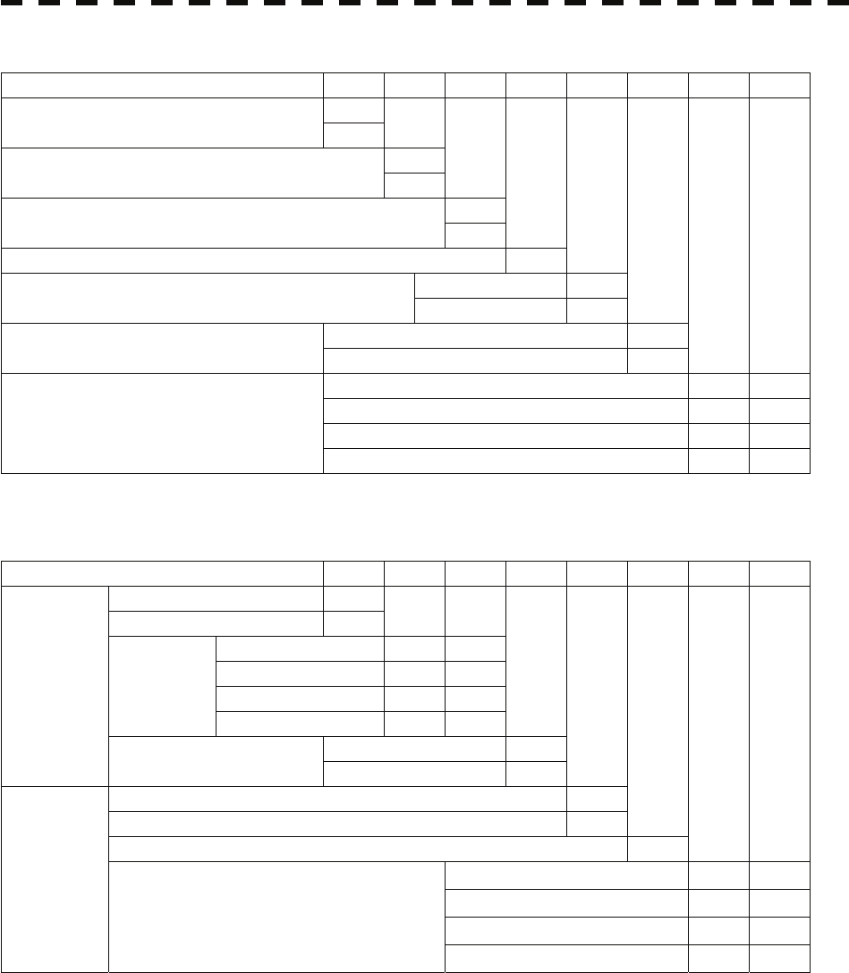
7-3
Table 7-1 Setting Table (S4 DIP Switch)
S4 SETTING 1 2 3 4 5 6 7 8
ON
BSHLOG ALM OFF
ON
GYRO SIMULATOR OFF
ON
LOG SIMULATOR OFF
N.C. (No Connection) OFF
5 SEC ON
GYRO ALM TIME 0.2 SEC OFF
HDT ( NMEA (HDT/THS) ) ON
GYRO SRC
(Heading Sensor Source) GYRO OFF
4800 BPS OFF OFF
9600 BPS ON OFF
19200 BPS OFF ON
NMEA BAUDRATE
38400 BPS ON ON
Table 7-2 Setting Table (S5 DIP Switch)
S5 SETTING 1 2 3 4 5 6 7 8
STEP ON
SYNC OFF
36X ON ON
90X OFF ON
180X ON OFF
RATIO
360X OFF OFF
REV (Reverce) ON
GYRO SETTING
DIRECTION NOR (Normal) OFF
SYNC (Synchro) ON
PULSE OFF
NC (No Connection) OFF
100P/30X ON ON
200P/90X OFF ON
400P/180X ON OFF
LOG SETTING
PULSE/NM
800P/360X OFF OFF
7-4
7.1 Settings at Installation yyy
yyyy
7
7.1.3 Tuning
[I] Tune Adjustment
Adjust the tuning control for the transmitter and receiver.
The turning control should be adjusted when the system is installed or when the magnetron is replaced.
Procedures 1. Set the 48NM range or more..
2. Open the Serviceman Menu.
3. Open the Tune Adjustment menu by performing the following menu
operation.
1. Adjust Menu
→ 1. Tune Adjustment
The tune mode switching (lower left of the display ⑫ on page 2-18) is changed to
MAN .
The tune dial position (lower left of the display on page 2-3) is changed to mediun
value.
4. Adjust the tune adjustment value so that the tune indicator bar at the
upper left of the display is maximized.
For how to input numeric data on the numeric value input screen, see Section 3.3.4.
5. Move the cursor onto the ENT button, and press the [ENT] key.
[II] Tune Indicator Adjustment
Set the scale mark at the time of which tuning reached the maximum point.
Procedures 1. Set the 48NM range or more..
2. Open the Serviceman Menu.
3. Open the Tune Indicator Adjust menu by performing the following
menu operation.
1. Adjust Menu
→ 4. TXRX Adjustment
→ 3. Tune Indicator Adjust
4. Adjust the tune indicator adjustment value so that the tune indicator
bar at the upper left of the display reaches a point of 80 to 90% of the
maximum.
For how to input numeric data on the numeric value input screen, see Section 3.3.4.
5. Move the cursor onto the ENT button, and press the [ENT] key.
7-5
7.1.4 Bearing Adjustment
Make adjustment so that the bearing of the target measured with the ship’s compass matches the bearing of
the target echo on the radar display.
Procedures 1. Select H Up for the bearing presentation. Set video processing
(PROC) to OFF.
2. Measure the bearing of an adequate target (e.g., a ship at anchor, a
breakwater, or a buoy) relative to own ship’s heading.
3. Open the Serviceman Menu.
4. Open the Bearing Adjustment menu by performing the following menu
operation.
1. Adjust Menu
→ 2. Bearing Adjustment
5. Adjust the bearing adjustment value so that the target measured in
step 2 is adjusted to the correct bearing.
For how to input numeric data on the numeric value input screen, see Section 3.3.4.
Make adjustment by the 0.1°.
6. Move the cursor onto the ENT button, and press the [ENT] key.
7.1.5 Range Adjustment
Make adjustment so that the range of a target on the radar display is shown correctly.
Procedures 1. Search the radar display for a target of which range is already known.
2. Open the Serviceman Menu.
3. Open the Range Adjustment menu by performing the following menu
operation.
1. Adjust Menu
→ 3. Range Adjustment
4. Adjust the range adjustment value so that the target measured in step
1 is adjusted to the correct range. (For inputs to the value input
screen, refer to Section 3.3.4.)
5. Move the cursor onto the ENT button, and press the [ENT] key.
7-6
7.1 Settings at Installation yyy
yyyy
7
7.1.6 Navigator Setting (Device)
Determine whether to connect navigators to the radar equipment.
Only the navigators set to ON here can be used.
Procedures 1. Open the Serviceman Menu.
2. Open the Device Installation menu by performing the following menu
operation.
2. Installation Menu
→ 9. Next
→ 3. Device Installation
3. Select On for navigators connected to the radar equipment, and
Off for navigators not connected.
GYRO : Gyro (via GYRO I/F)
Compass : Compass (Compliant with IEC61162)
GPS Compass : GPS compass produced by JRC
Log : Log (via GYRO I/F)
2AXW : 2-axis log (Speed over water: Compliant with IEC61162)
2AXG : 2-axis log (Speed over ground: Compliant with IEC61162)
GPS : GPS (Compliant with IEC61162)
7.1.7 Setting of True Bearing Value
If GYRO I/F is used to input a gyro signal, the true bearing value indicated by the master gyro does not
match the value indicated by the radar equipment only in a rare case. In this case, perform the following
procedure to adjust the true bearing value of the radar equipment to the value of the master gyro.
Procedures 1. Press the [RADAR MENU] key twice.
2. Open the GYRO Setting menu by performing the following menu
operation.
4. NAV Equipment Setting
→ 1. GYRO Setting
3. Input the master gyro value to the value input screen. (For inputs to
the value input screen, refer to Section 3.3.4.)
4. Move the cursor onto the ENT button, and press the [ENT] key.
7-7
7.1.8 Antenna Height Setting (Antenna Height)
Set the height of radar antenna above sea level. Do not change this setting carelessly.
Procedures 1. Measure the height of radar antenna above sea level in advance.
2. Open the Serviceman Menu.
3. Open the Antenna Height menu by performing the following menu
operation.
1. Adjust Menu
→ 4. TXRX Adjustment
→ 1. Antenna Height
4. Select the setting that matches the antenna height measured in step 1.
7-8
7.1 Settings at Installation yyy
yyyy
7
7.1.9 Setting of CCRP/Antenna/GPS Antenna Position (CCRP
Setting)
Set the own ship's CCRP location, radar antenna installation location, and GPS installation location.
CCRP : Up to four locations can be input. (One location selected when used)
Radar antenna : Up to eight radar antennas can be input. (Automatically selected in response to
ISW operation)
GPS : Up to four locations can be input. (One location selected when used)
Procedures 1. Measure the CCRP location, radar antenna location, and GPS antenna
location in advance.
2. Open the Serviceman Menu.
3. Open the CCRP Setting menu by performing the following menu
operation.
2. Installation Menu
→ 4. CCRP Setting
4. Specify the ship length for Length at the upper right of the CCRP
Setting Menu, and the ship width for Beam.
5. Move the cursor onto the CCRP1 X, Y value, and press the ENT key to
input the CCRP1 location.
When X > 0, the CCRP is on the starboard side of the ship. When X < 0, it is on the
port side.
6. To input the second CCRP, press the CCRP2 button to display the
CCRP2 X,Y value, and input the value in the same manner for step 5.
Similarly, input the third and subsequent CCRPs.
7. Repeat the above steps to input the GPS location(s) and radar
antenna location(s).
8. If multiple CCRP locations and GPS locations are input, select the
CCRP location and GPS location to be used by pressing the buttons at
the upper left of the menu.
9. Press [0] key to close the CCRP Setting menu.
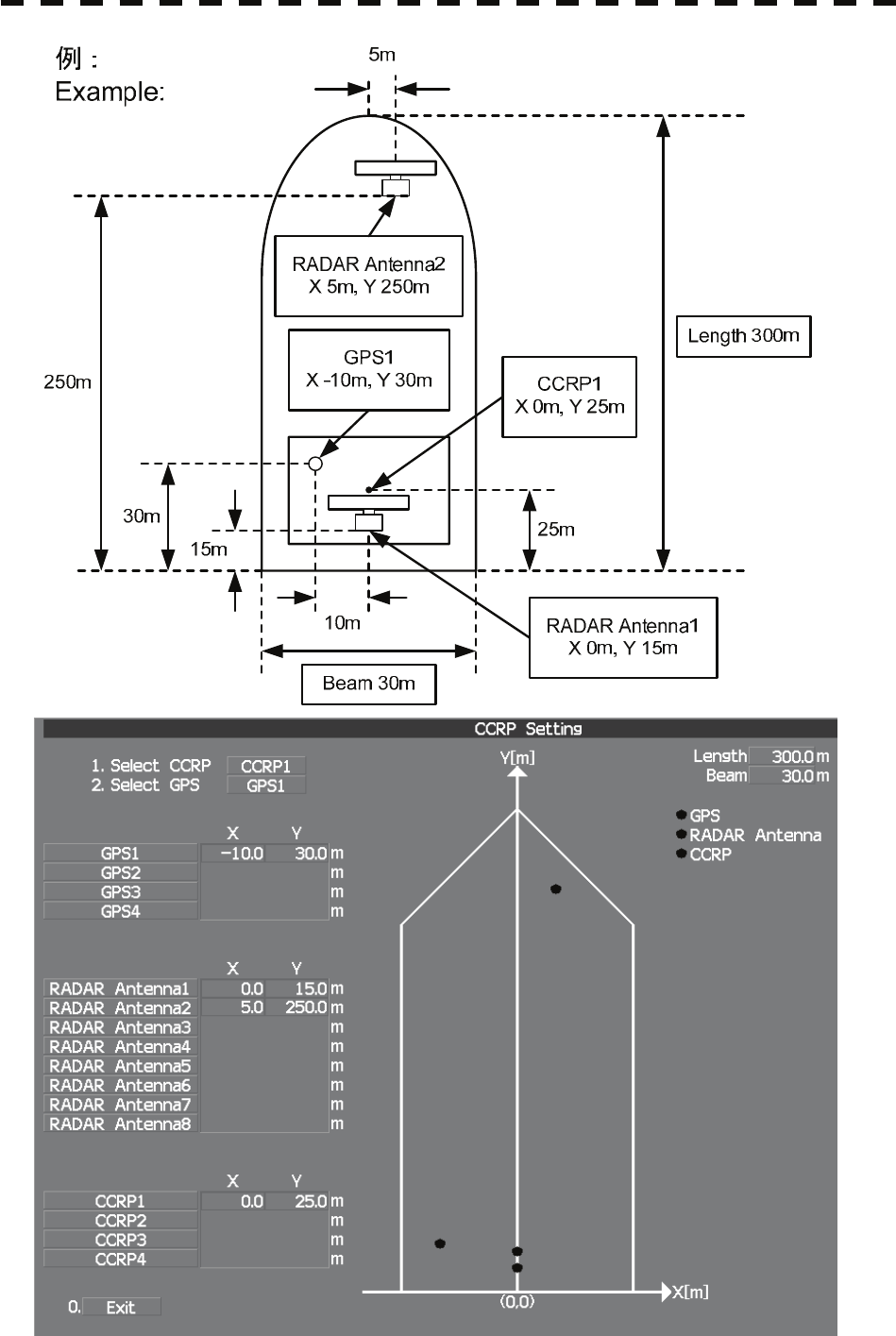
7-9
7-10
7.2 Settings yyy
yyyy
7
7.2 SETTINGS
This section describes the electrical adjustment procedures to be performed by service engineers during
system installation.
CAUTION
Any adjustments must be made by specialized service
personnel.
Incorrect settings may result in unstable operation.
Do not make any adjustments during navigation. Failure
to comply may result in adverse effects on the radar
function which may lead to accidents or equipment failure.
7.2.1 Communication Port Setting (COM Port Setting)
External sensor signals are input to the radar equipment through a communication port. The radar
equipment has five communication ports. For signals to be input from sensors or to be output to the
sensors, communication ports need to be set in accordance with the sensors.
[I] Baud Rate Setting
Set the baud rate of the signal to be input to the COM port.
Procedures 1. Open the Serviceman Menu.
2. Open the Baud Rate menu by performing the following menu
operation.
2. Installation Menu
→ 5. COM Port Setting
→ 1. Baud Rate
7-11
3. Set the baud rate of the port to be set.
Selection value
1. COMPASS : 4800(NMEA)/9600(NSK)/38400(Fast NMEA) bps
2. NAV1 : 1200/4800/9600/38400 bps
3. NAV2 : 1200/4800/9600/38400 bps
4. GPS : 1200/4800/9600/38400 bps
5. NMEA : 1200/4800/9600/38400/115200 bps
The bold values are factory-set.
The COMPASS port is a receive-only port that is dedicated to COMPASS signals.
[II] Reception Port Setting (RX Port)
Set the numbers of ports for receiving signals from sensors.
There are two methods for receiving signals: specifying a port for each sensor, or using the automatic
recognition function without specifying ports.
Procedures 1. Open the Serviceman Menu.
2. Open the RX Port menu by performing the following menu operation.
2. Installation Menu
→ 5. COM Port Setting
→ 2. RX Port
3. Set a port for each sensor.
Settable sensor signals
GPS, DLOG, Alarm, Depth, Temperature, Wind, Current, ROT, RSA
Selectable ports
When the automatic recognition function is used: AUTO
When ports are specified: NAV1, NAV2, GPS, and NMEA
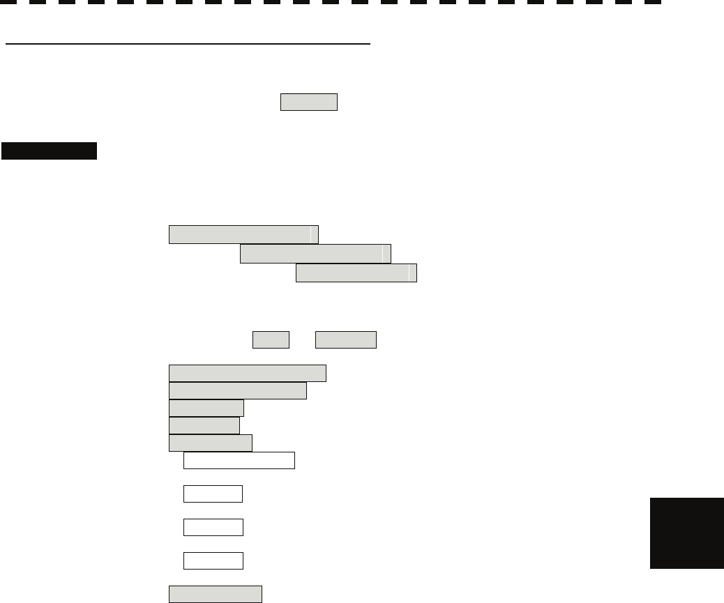
7-12
7.2 Settings yyy
yyyy
7
[III] Reception Sentence Setting (RX Sentence)
Set signal sentences to be received from sensors.
The system is factory-set for using all sentences.
To receive only specified sentences, select No Use for sentences which are not necessary.
Procedures 1. Open the Serviceman Menu.
2. Open the RX Sentence menu by performing the following menu
operation.
2. Installation Menu
→ 5. COM Port Setting
→ 3. RX Sentence
3. Select the sentences to be used by the sensors to be set.
Selection value: Use or Not Use can be selected for each sentence.
1. GPS(LL/COG/SOG) > : GGA/RMC/RMA/GNS/GLL/VTG
2. GPS(WPT/Time) > : GGA/RMC/RMB/BWC/BWR/ZDA
3. Depth > : DPT/DBK/DBT/DBS
4. Wind > : MWV/MWD
5. Current > :
Data Set Number : 0-9. Set the number of the sentence to be used by
Data Set Number. (Initial value All)
Layer A : 0-999. Set the number of the sentence to be used
with layer A by Layer Number. (default value : 3)
Layer B : 0-999. Set the number of the sentence to be used
with layer B by Layer Number. (default value : 4)
Layer C : 0-999. Set the number of the sentence to be used
with layer C by Layer Number. (default value : 5)
6. Autopilot > : APB (default value : Not Use)

7-13
[IV] Transmission Port Setting (TX Port)
For each sentence, set a communication port through which signals are transmitted to sensors.
Procedures 1. Open the Serviceman Menu.
2. Open the TX Port menu by performing the following menu operation.
2. Installation Menu
→ 5. COM Port Setting
→ 4. TX Port
3. Select the communication port through which the sentence to be set
is output.
Settable sentences
TTM(TT), TLL(TT), TTD(TT), TLB(TT), OSD, RSD, ALR, ACK,
TTM(AIS), TLL(AIS), TTD(AIS), TLB(AIS), RemoteMaintenance,
JRC-ARPA, APB, BOD, GGA, GLL, RMC, RMB, VTG, XTE,
BWC, HDT, THS
Selectable ports
NAV1, ARPA, GPS, and NMEA
4. Select the output format, talker, and transmission interval.
Signals for which the above items can be set:
• NMEA0183 Output Format
Signal names: APB, BOD, GGA, GLL, RMC, RMB,VTG, XTE, BWC, HDT, THS
Selection Value: V1.5, V2.0, and V2.3
• NMEA0183 Talker
Signal names: APB, BOD,RMB, XTE, BWC, HDT, THS
Selection Value:
Standard: The talker is RA.
GP: The talker is GP.
For TTM, TLL, TTD, TLB, OSD, RSD and ALR the talker is always RA .
For GGA, GLL, RMC, and VTG, the talker is always GP.
• NMEA0183 TX Interval
Signal names: APB, BOD, GGA, GLL, RMC, RMB,VTG, XTE, BWC, HDT, THS
Selection Value: Set an interval in the range 1 to 9 seconds.
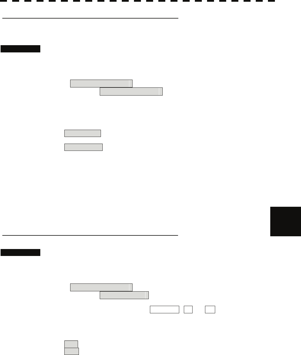
7-14
7.2 Settings yyy
yyyy
7
[V] GPS Receive Port Setting (Select NAV Equipment)
Select the receive port of GPS data.
Procedures 1. Open the Serviceman Menu.
2. Open the COM Port setting menu by performing the following menu
operation.
2. Installation Menu
→ 5. COM Port Setting
3. Press the [5] key.
Units of Select NAV Equipment are switched.
Internal GPS : The receive port is selected GPS connector of processor unit
(JRC’s GPS).
External GPS : The receive port is selected GPS terminal of terminal board
circuit.
7.2.2 Sector Blank Setting (Sector Blank)
In order not to display radar echoes, set a sector and stop transmission in the bearing. Three sector blank
areas can be created.
The sector blank function operates in the relative bearing with the bow.
[I] Sector Blank Function On/Off (Sectors 1, 2, and 3)
Procedures 1. Open the Serviceman Menu.
2. Open the Sector Blank menu by performing the following menu
operation.
2. Installation Menu
→ 3. Sector Blank
3. Set the sector blank number Sector 1 , 2 , or 3 with which the
sector blank function operates.
The system allows the use of up to three sector blank areas.
Set each sector blank area to on or off.
On : The sector blank function is operated.
Off : The sector blank function is stopped.
7-15
[II] Sector Blank Area Creation (Make Sectors 1, 2, and 3)
Procedures 1. Transmit the radar.
2. Open the Serviceman Menu.
3. Open the Sector Blank menu by performing the following menu
operation.
2. Installation Menu
→ 3. Sector Blank
4. Press numeric keys corresponding to the desired sector creation
Make Sector 1 , 2 , or 3 .
The selected sector blank will be made.
5. Set the starting bearing of the sector blank by operating the [EBL] dial,
and press the [ENT] key.
6. Set the ending azimuth of the sector blank by operating the [EBL] dial,
and press the [ENT] key.
7.2.3 TNI Blank Setting (TNI Blank)
Set a sector and stop tuning operation in the bearing.
If a structure such as the mast is close to the radar antenna, automatic tuning operation may become
unstable. In this case, set a TNI blank in the direction of the structure in order to stabilize the tuning
operation.
Only one TNI blank sector can be created. The TNI blank function operates in the relative bearing with
the bow as the benchmark.
[I] TNI Blank Function On/Off (Sector)
Procedures 1. Open the Serviceman Menu.
2. Open the TNI Blank menu by performing the following menu
operation.
2. Installation Menu
→ 9. Next
→ 2. TNI Blank
3. Select the item 1. TNI Blank in the menu, and turn on or off the TNI
blank function.
On : The TNI blank function is operated.
Off : The TNI blank function is stopped.
7-16
7.2 Settings yyy
yyyy
7
[II] TNI Blank Area Creation (Make Sector)
Procedures 1. Transmit the radar.
2. Open the Serviceman Menu.
3. Open the TNI Blank menu by performing the following menu
operation.
2. Installation Menu
→ 9. Next
→ 2. TNI Blank
4. Press the 2. Make Sector button in the menu.
5. Set the starting bearing of the TNI blank by operating the [EBL] dial,
and press the [ENT] key.
6. Set the ending bearing of the TNI blank by operating the [EBL] dial,
and press the [ENT] key.
7.2.4 Setting of Bearing Pulses from Antenna (Output Pulse)
Set the output value of bearing pulses from the antenna. The system can set 2048 pulses or 4096 pulses.
Procedures 1. Open the Serviceman Menu.
2. Open the Output Pulse menu by performing the following menu
operation.
1. Adjust Menu
→ 4. TXRX Adjustment
→ 6. Output Pulse
3. Set the number of pulses to be output by the antenna.
2048 : 2048 pulses per antenna rotation (Recommended value)
4096 : 4096 pulses per antenna rotation
7-17
7.2.5 Slave Mode Setting (Master/Slave)
Place the system in the Slave mode when it is to be operated as the sub-display that displays radar
echoes by using radar signals from other radar equipment.
The input value of externally input bearing pulses can be set. The system can set 2048 pulses or 4096
pulses.
[I] Slave Mode Setting (Master/Slave)
Procedures 1. Open the Serviceman Menu.
2. Open the Installation Menu by performing the following menu
operation.
2. Installation Menu
3. Select Slave for the item 2. Master/Slave in the menu.
Master : The system operates as radar equipment while the own antenna is
connected.
Slave : The system operates as a sub-display while the signal cable of other radar
equipment is connected.
[II] Setting of Input Bearing Pulse (Input BP Count)
Procedures 1. Open the Serviceman Menu.
2. Open the second page of the Installation Menu by performing the
following menu operation.
2. Installation Menu
→ 9. Next
3. Set the number of pulses for the item 1. Input BP Count in the
menu.
2048 : 2048 pulses per antenna rotation
4096 : 4096 pulses per antenna rotation
7-18
7.2 Settings yyy
yyyy
7
7.2.6 Language Setting (Language)
The system is designed to switch between display languages, English and Japanese.
Procedures 1. Open the Serviceman Menu.
2. Open the Language menu by performing the following menu
operation.
2. Installation Menu
→ 8. Language
3. Select the language to be used.
1. English
2. Japanese
3. Other
3. Other is an option to display character strings created by our agents.
Ask the agent or our sales department if your language is supported.
4. To determine the selected language, turn the radar off, and then turn it
on.
7.2.7 Date Time Setting
To display time, the local time, local date, and time-zone difference must be set.
However, if the "ZDA" sentence of NMEA0183 is received, time can be automatically displayed.
Procedures 1. Press the [RADAR MENU] key twice.
2. Open the Date/Time Setting menu by performing the following menu
operation.
5. Sub Menu
→ 6. Date/Time Setting
7-19
2. Set information about date and time.
[1] UTC/LMT (Time display system)
UTC : Universal Time Coordinate
LMT : Local Mean Time
[2] LMT Date
Input the date in local time.
[3] LMT Time
Input the time in local time.
[4] Time Zone
Input the time-zone difference between the universal time and local time.
[5] Display Style
Set one of the following date display formats.
YYYY-MM-DD : Example: 2007-12-31
MMM DD, YYYY : Example: Dec 31, 2007
DD MMM YYYY : Example: 31 Dec 2007
[6] Synchronize with GPS
A ZDA sentence sent by the GPS is used, thereby displaying time synchronized
with the GPS time.
On : Time synchronized with the GPS time
Off : Time not synchronized with the GPS time
* If On is selected for this item but a ZDA sentence is not input, the system
internal clock function is used to display the date and time.
7.2.8 Input Installation Information
The system can input installation information.
Procedures 1. Open the Serviceman Menu.
2. Open the Installation Information menu by performing the following
menu operation.
2. Installation Menu
→ 1. Installation Information
3. Input the installation information.
For the input method on the numeric value and character input screens, see Section
3.3.4.
[1] Date
Input the date of installed system.
[2] Name
Input the name of installation personel.
[3] Company
Input the name of radar installer.
7-20
7.2 Settings yyy
yyyy
7
7.2.9 Setting the Alarm System
Setting the relay output (Relay Output)
This function enables the control of ARPAALM terminal (on the terminal board
circuit).
Procedures 1. Open the Serviceman Menu.
2. Open the Relay Output menu by performing the following menu
operation.
2. Installation Menu
→ 6. Alarm System
→ 2. Relay Output
3. Press the [1] key.
The Relay Output mode is switched.
Continuous : The output is continuously controlled.
Intermittent : The output is intermittenly controlled.
4. Press the [numeric] key corresponding to the item to be changed.
The item can be turned on / off.
On : The relay output is turned on when alarm have issued.
Off : The relay output is not turned on when alarm have issued.
2. TT CPA/TCPA : There is a dangerous target. (tracked target)
3. AIS CPA/TCPA : There is a dangerous target. (AIS target)
4. New Target : A new target is acquired in the automatic acquisition zone.
5. Lost : There is a lost target. (Target Tracking / AIS).
6. RADAR Alarm : Targets have entered the radar alarm range.
Setting the ALR output (ALR Output)
This function enables the control of ALR port (See the section 7.2.1).
Procedures 1. Open the Serviceman Menu.
2. Open theALR output menu by performing the following menu
operation.
2. Installation Menu
→ 6. Alarm System
→ 3. ALR Output
3. Press the [numeric] key corresponding to the item to be changed.
The item is turned on / off.
On : The ALR sentence is output when alarm have issued.
Off : The ALR sentence is not output when alarm have issued.
1. System Alarm : The internal alarm.
2. TT/AIS Alarm : Target Tracking Alarms and AIS Function Alarms.
7-21
Setting the External Acknowledgement (External ACK Setting)
This function enables the control of system when ACK sentence have received.
Procedures 1. Open the Serviceman Menu.
2. Open the External ACK Setting menu by performing the following
menu operation.
2. Installation Menu
→ 6. Alarm System
→ 5. External ACK Setting
3. Press the [numeric] key corresponding to the menu to be changed.
Critical Alarm :CPA/TCPA alarm.
Normal Alarm :Exept Critical Alarm.
4. Press the [numeric] key corresponding to the item to be changed.
The item is switched.
Audio : Setting of alarm sound.
On : The alarm sound is not stopped when acknowridgement have
received.
Off : The alarm sound is stopped when acknowridgement have
received.
Indication : Setting of alarm indication.
Lighting : The alarm indication brinking is stopped when
acknowridgement have received.
Brinking : The alarm indication brinking is not stopped when
acknowridgement have received.
Acknowridge State : Setting of ALR sentence.
A:ACK : Add acknowridgement to ALR sentence.
V:UNACK : Add no acknowridgement (unrecognized) to ALR
sentence.
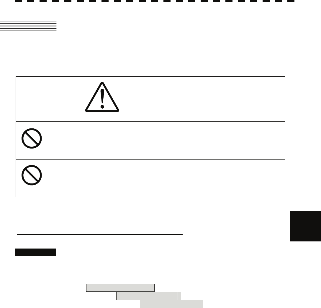
7-22
7.3 Adjustment yyy
yyyy
7
7.3 ADJUSTMENT
This section describes the electrical adjustment procedures to be performed by service engineers during
system installation.
CAUTION
Any adjustments must be made by specialized service
personnel.
Incorrect settings may result in unstable operation.
Do not make any adjustments during navigation. Failure
to comply may result in adverse effects on the radar
function which may lead to accidents or equipment failure.
7.3.1 Noise Level Adjustment (Noise Level)
[I] Noise Level Adjustment for Signal Processing
Procedures 1. Open the Serviceman Menu.
2. Open the Echo Noise Level menu by performing the following menu
operation.
9. SP/TT Initial Setup
→ 1. Signal Processing
→ 1. Echo Noise Level
3. Increase/decrease the noise level adjustment value.
The noise level is factory-set.
After system installation, a great change in the noise level adjustment value should be
avoided; it should be fine adjusted within ±5.

7-23
[II] Noise Level Adjustment Mode (Setting Mode)
A noise level is factory-adjusted while this mode is turned on.
Procedures 1. Open the Serviceman Menu.
2. Open the Signal Processing menu by performing the following menu
operation.
9. SP/TT Initial Setup
→ 1. Signal Processing
3. Press the [2] key.
The noise level setting mode is switched between on and off.
Factory-adjustment method
• The GAIN control is set to the maximum position, the SEA control is set to the
minimum position, the RAIN control is set to the minimum position, and IR,
AUTO-SEA, AUTO-RAIN, PROC, FUNC, and TRAILS are all set to off.
• The noise level adjustment mode is turned on.
• While the noise level adjustment value is decreased gradually, the value with which
radar echoes no longer appear is determined as the set value.
• Ten is added to the set value (with which radar echoes no longer appear), and the
result is set as the final noise level adjustment value.
• The noise level adjustment mode is turned off when the adjustment is finished.
7-24
7.3 Adjustment yyy
yyyy
7
z Do not change the set value carelessly.
The vector constant shall be set to 4 normally. If the
vector constant value is higher, a target’s vector will be
better followed up when the target and own ship
change their course or speed, but the vector accuracy
will be lower on the contrary.
7.3.2 Adjustment of Target Tracking Function (TT)
CAUTION
Optimal values have been set for Video Level and Vector
Constant; therefore, never change their values unless
absolutely necessary. Failure to comply may result in
accidents that would lower target tracking performance.
[I] Vector Constant Adjustment (Vector Constant)
Adjust the vector follow-up performance of the target tracking function.
The vector constant is adjusted to an optimal value, so do not change it carelessly.
Procedures 1. Open the Serviceman Menu.
2. Open the Vector Constant menu by performing the following menu
operation.
9. SP/TT Initial Setup
→ 2. TT
→ 1. Vector Constant
3. Input the value to be set.
To improve vector follow-up performance, increase the set value.
To stabilize vectors, decrease the set value.
Attention
7-25
[II] Quantization Level Adjustment (Video Level)
Use the target tracking function (TT) to adjust the level of the signal to be recognized as a target. If a
small value is set, even weak target signals will be input to the target detection circuit of the target tracking
function. However, many unnecessary signals are also input, which may cause unstable target acquisition
or tracking. It is important to set a value four or five greater than the value with which unnecessary signals
are detected.
The quantization level is adjusted to an optimal value, so do not change it carelessly.
CAUTION
Do not change the quantization level settings unless
absolutely necessary. If set at an inappropriate value, the
target acquisition or target tracking function deteriorates,
and this may lead to accidents.
Procedures 1. Open the Serviceman Menu.
2. Open the TT (Target Tracking) menu by performing the following menu
operation.
9. SP/TT Initial Setup
→ 2. TT
3. To change the quantization level of the automatic acquisition area,
specify the item 2. Video TD Level in the menu. To change the
quantization level of tracking and manual acquisition, specify the item
3. Video High Level .
7-26
7.3 Adjustment yyy
yyyy
7
[III] Gate Size Adjustment (Gate Size)
Use the target tracking function (TT) to set a target search area.
The gate size is adjusted to an optimal value, so do not change it carelessly.
Procedures 1. Open the Serviceman Menu.
2. Open the Gate Size menu by performing the following menu
operation.
9. SP/TT Initial Setup
→ 2. TT
→ 5. Gate Size
3. Select a gate size.
Wide : Large gate size
Normal : Medium gate size
Narrow : Small gate size
[IV] CPA Limit Ring Display On/Off (Limit Ring)
Use the target tracking function (TT) to determine whether to display the CPA limit for determining a
dangerous ship. When the CPA limit ring display function is turned on and a relative vector is used, the
CPA limit ring is displayed as a red circle.
Procedures 1. Open the Serviceman Menu.
2. Open the TT (Target Tracking) menu by performing the following menu
operation.
9. SP/TT Initial Setup
→ 2. TT
3. Press the [6] key.
The Limit Ring item is turned on / off.
Off : Limit ring not displayed
On : Limit ring displayed
7-27
7.3.3 Main Bang Suppression Adjustment (MBS)
Main Bang Suppression is adjusted to suppress main bang, a reflection signal from 3D circuit including
wave guide tube, that generally appears as a circular video focusing on the center of the radar display.
Optimum adjustment allows main bang video to remain slightly on the display.
WARNING
Do not change MBS Level/Area unless absolutely
necessary.
Incorrect adjustment will result in deletion of nearby target
images and thus collisions may occur resulting in death or
serious injuries.
Procedures 1. Open the Serviceman Menu.
2. Open the MBS menu by performing the following menu operation.
9. SP/TT Initial Setup
→ 3. MBS
3. Set the radar as follows:
• Set the radar video enhance function and video processing (PROC) to OFF.
• Turn the [RAIN] control to the minimum position (fully to the left).
• Turn the [GAIN] control to the maximum position (fully to the right).
• Turn the [SEA] control to achieve the strength with which main bang can be judged.
4. Set 20 for 2. MBS Area .
5. Adjust the value set for 1. MBS Level so that the main bang
remains slightly.
6. Adjust the value set for 2. MBS Area so that the suppression area
will match the main bang.
7-28
7.4 Maintenance Menu yyy
yyyy
7
7.4 MAINTENANCE MENU
This item is provided for equipment maintenance, including settings of antenna safety switch, master reset,
etc.
CAUTION
Any adjustments must be made by specialized service
personnel.
Failure to comply may result in accidents or equipment
failure.
Do not make any adjustments during navigation. Failure
to comply may result in adverse effects on the radar
function which may lead to accidents or equipment failure.
7.4.1 Antenna Safety Switch (Safety Switch)
Use this switch to measure the transmission/reception performance while the antenna is in stopped state.
Procedures 1. Open the Serviceman Menu.
2. Open the Safety Switch menu by performing the following menu
operation.
3. Maintenance Menu
→ 1. Safety Switch
3. Select the item to be set.
Set operation when the antenna safety switch is turned off.
1. TX-Off :
The transmitter stops transmission.
The display unist remains in transmission state.
2. Standby : (Normal setting)
The transmitter stops transmission.
The display unit is placed in standby state.
3.TX-On :
The transmitter continues transmission.
The display unit remains in transmission state.
4. Change the setting back to 2. Standby when the work is finished.
7-29
7.4.2 Initialization of Memory Area (Area Initial)
If system operation is unstable, it may be stabilized by initializing the memory area. To initialize the
memory area, follow the procedure in this section. The memory area is reset to the factory setting when
initialized.
[I] Partial Master Reset
Procedures 1. Open the Serviceman Menu.
2. Open the Partial Master Rest menu by performing the following menu
operation.
3. Maintenance Menu
→ 2. Area Initial
→ 1. Partial Master Reset
3. Select the items to be initialized.
Serviceman Menu : The set values in the Serviceman menu are initialized.
Except Serviceman Menu : The set values not in the Serviceman menu are
initialized.
User Setting : The user setting values are initialized.
TT Setting : The set values for the target tracking function are
initialized.
AIS Setting : The set values for the AIS function are initialized.
Day/Night : The color scheme and brilliance setting for the day/night
mode are initialized.
JRC Card Copy Record : The history of JRC charts copied on the memory card is
erased.
4. Select Yes in the Confirmation Window.
The memory areas of specified items are initialized, and the system is restarted.
[II] All Master Reset
Procedures 1. Open the Serviceman Menu.
2. Open the All Master Rest menu by performing the following menu
operation.
3. Maintenance Menu
→ 2. Area Initial
→ 2. All Master Reset
3. Select Yes in the Confirmation Window.
The whole memory area is initialized, and the system is restarted.
7-30
7.4 Maintenance Menu yyy
yyyy
7
7.4.3 Save of Internal Memory Data (Card1/2)
The system can save internal memory data such as item settings in all menus onto a flash memory card. If
the radar processing circuit in the system has been replaced, the set values before the circuit replacement
can be restored by reading the set values you saved before the replacement.
To save the internal memory data onto a flash memory card (option), the card must be inserted in card slot
beforehand.
[I] Copying of Internal Settings onto Card (Internal to Card1/2)
Save the internal memory data, such as item settings in menus, onto a flash memory card.
The internal memory data should be saved at completion of system setting, and the operation condition
should be saved periodically.
Procedures 1. Open the Serviceman Menu.
2. Open the Internal to Card 1/2 menu by performing the following menu
operation.
3. Maintenance Menu
→ 3. Internal to Card1/2
3. Select the slot of the card on which the internal memory data is to be
saved.
The lower slot is slot 1; the upper slot is slot 2.
4. Select Yes in the Confirmation Window.
The internal memory data is saved on the flash memory card.
[II] Reading of Internal Settings from Card (Card1/2 to Internal)
Read the saved memory data from the flash memory card into the system memory.
Perform the read operation in order to return the system to the previous operation condition after
replacement of the radar processing circuit in the system.
Procedures 1. Open the Serviceman Menu.
2. Open the Card 1/2 to Internal menu by performing the following menu
operation.
3. Maintenance Menu
→ 4. Card1/2 to Internal
3 Select the slot of the card from which the previously saved internal
memory data is to be read.
The lower slot is slot 1; the upper slot is slot 2.
4. Select Yes in the Confirmation Window.
The memory data is read from the flash memory card into the system memory.
After the internal memory area is updated, the system is restarted.

7-31
7.4.4 Clear and Save/Restoration of Antenna Operation Time
(TXRX Time)
The system adds up the following operation time and contains it in the antenna unit:
• Transmission time
• Motor run time
Clear the above total time when the magnetron or antenna unit motor is replaced.
[I] Clear of Transmission Time (Clear TX Time)
Clear the transmission time of the antenna unit.
Perform the following procedure to clear the transmission time when the magnetron is replaced.
Procedures 1. Open the Serviceman Menu.
2. Open the Clear TX Time menu by performing the following menu
operation.
3. Maintenance Menu
→ 5. TXRX Time
→ 1. Clear TX Time
3. Select Yes in the Confirmation Window.
The transmission time in the antenna's internal control circuit is cleared to 0.
[II] Clear of Motor Run Time (Clear Motor Time)
The Clear Motor Time Function is unavailable in The JMA-5352-9R and JMA-5362-8R.
[III] Save of Antenna Time (TXRX to Display Unit)
The TXRX to Display Unit Function is unavailable in The JMA-5352-9R and JMA-5362-8R.
[IV] Restoration of Antenna Time (Display Unit to TXRX)
The Display Unit to TXRX Function is unavailable in The JMA-5352-9R and JMA-5362-8R.
7-32
7.4 Maintenance Menu yyy
yyyy
7
7.4.5 Update of Character String Data (String Data Update)
The system is designed to transfer and display external character strings as the second language display.
The second language is factory-set to "Japanese."
Ask our agent or sales department for the supply of character strings to be updated.
To update character strings, the flash memory card (option) containing the character string file must be
inserted in card slot 2.
Procedures 1. Open the Serviceman Menu.
2. Open the String Data Update menu by performing the following menu
operation.
3. Maintenance Menu
→ 6. String Data Update
3. Select Yes in the Confirmation Window.
The character string file on the flash memory card is read into the system, and the
second language area is updated.
To display the read character strings in the second language, select Other in the
menu shown in Section 7.2.6.

SECTION 8
MAINTENANCE
8.1 ROUTINE MAINTENANCE................................................................. 8-1
8.2 MAINTENANCE ON EACH UNIT ....................................................... 8-2
8.3 PERFORMANCE CHECK................................................................... 8-6
8.4 REPLACEMENT OF MAJOR PARTS ...............................................8-11
8-1
8.1 ROUTINE MAINTENANCE
DANGER
Never carry out internal inspection or repair work of the
equipment by users.
Inspection or repair work by uncertified personnel may
result in fire hazard or electrocution.
For inspection and repair work of equipment components,
consult with our branch office, branch shop, sales office, or
our distributor in your district.
When conducting maintenance, make sure to turn the main
power off.
Failure to comply may result in electrocution.
Turn off the main power before cleaning the equipment.
Especially when a rectifier is used, make sure to turn it off
since voltage is still outputted from the rectifier even after
the indicator and the radar are turned off. Failure to
comply may result in equipment failure, or death or serious
injury due to electric shock.
For operating the radar equipment in the good conditions, it is necessary to make the maintenance work as
described below. If maintenance is made properly, troubles will reduce. It is recommended to make
regular maintenance work.
Common points of maintenance for each unit are as follow:
Clean the equipment.
Remove the dust, dirt, and sea water rest on the equipment cabinet with a piece of dry cloth.
Especially, clean the air vents with a brush for good ventilation.
8-2
8.2 Maintenance on each Unit yyyy
yyyy
8
8.2 MAINTENANCE ON EACH UNIT
8.2.1 Scanner Unit NKE-1064/3710-8
DANGER
When conducting maintenance work on the scanner, make
sure to turn its main power off.
Failure to comply may result in electrocution or injuries.
Make sure to turn off the scanner safety switch. Failure to
comply may result in injuries caused by physical contact
with the rotating scanner.
Do not touch the radiator. Even if the power is turned off,
the radiator may be rotated by the wind.
After the work, turn "ON" the scanner unit safety switch.
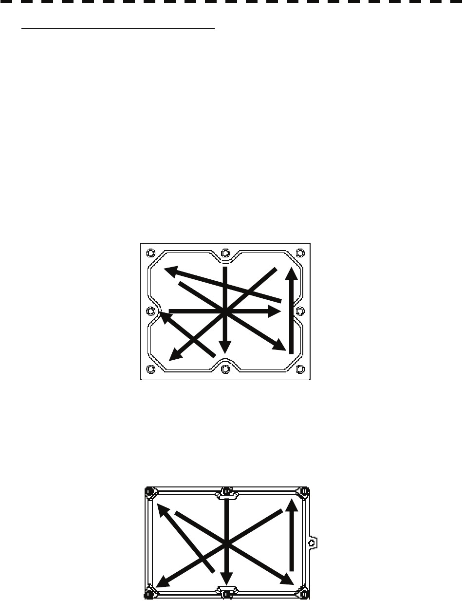
8-3
Precautions in Mounting the Cover
When the cover is removed for regular checkup and replacement of parts and refitted after such work, the
procedures of fastening bolts shall be taken with the following precautions:
(a) The proper fastening torque of the fitting bolts (M8) is 1176 to 1470 N-cm (120 to 150 kgf-cm) (which
makes the inside water-tight and protects the packing against permanent compressive strain).
The packing start producing from the cover at a torque of approximately 1470 N-cm (150 kgf-cm).
Do not fasten the bolts with a torque exceeding the specified value. Otherwise, the screws may be
broken.
(b) Use an offset wrench of 11 mm × 13 mm or a double-ended wrench of 13 mm × 17 mm (not longer
than 200 mm).
(c) Screw all the bolts by hand first to prevent them playing, then fasten them evenly in order not to cause
one-sided fastening. (Fasten the bolts with 25% of the required torque at the first step.)
*: Fasten the bolts in the diagonal order.
Side View of NKE-1064
Bolt Tightening Procedure of NKE-1064 Cover
Side View of NKE-3710-8
Bolt Tightening Procedure of NKE-3710-8 Cover
①
③ ④
②
⑤
⑥
⑦
⑧
① ③
④ ②
⑤
⑥

8-4
8.2 Maintenance on each Unit yyyy
yyyy
8
z If the radiator front face (radiation plane) is soiled with
smoke, salt, dust, paint or birds’ droppings, wipe it
with a piece of soft cloth wetted with alcohol or water
and try to keep it clean at all times. Otherwise, radar
beam radiation may attenuate or reflect on it, resulting
in deterioration of radar performance.
z Never use solvents of gasoline, benzine,
trichloroethylene and ketone for cleaning.
(1) Radiator
Check up and clean the radiator.
(2) Rotating section
(a) Supply Oil Seal
An scanner unit with a grease nipple needs grease supply. Remove the cap of the grease nipple
on the front of the radiator support, and supply grease with a grease gun.
Make the oiling every six months. The oil quantity shall be approximately 100 g, which is as
much as the grease comes out of the oil seal. Use the grease of Mobilux 2 of Mobil Oil.
(b) Oiling gears
Apply grease evenly to the tooth surfaces of the main shaft drive gear and the encoder drive gear
with a spreader or brush. Oiling in short intervals is more effective to prevent the gears from
wear and tear and extend their service life, but oil at least every six months.
Use Mobilux2 of Mobile Oil.
(c) Mounting legs
Check the mounting legs and mounting bolts of the scanner unit case for corrosion at intervals
and maintain them to prevent danger. Apply paint to them once a half year because painting is
the best measure against corrosion.
Attention
8-5
8.2.2 Display Unit NCD-4530
WARNING
When cleaning the display screen, do not wipe it too
strongly with a dry cloth. Also, do not use gasoline or
thinner to clean the screen. Failure to comply will result in
damage to the screen surface.
Dust accumulated on the screen will reduce clarity and darken the video. For cleaning it, wipe it with a
piece of soft cloth (flannel or cotton). Do not wipe it strongly with a piece of dry cloth nor use gasoline or
thinner.
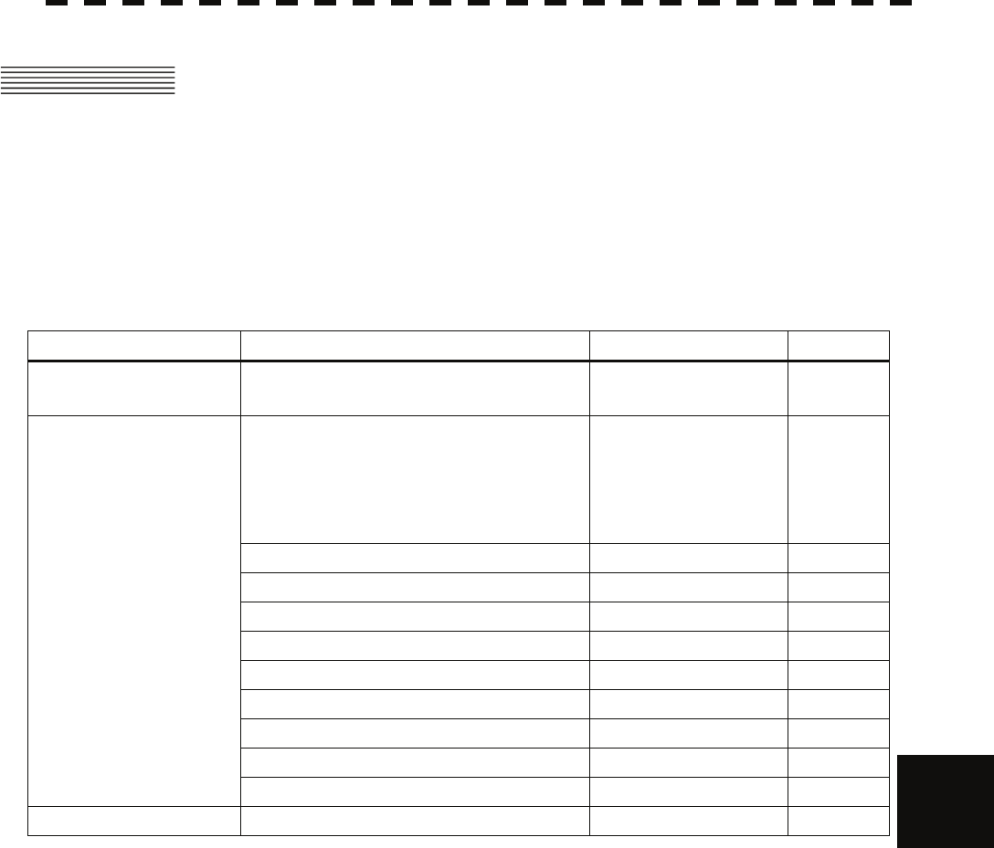
8-6
8.3 Performance Check yyyy
yyyy
8
8.3 PERFORMANCE CHECK
Make operational check on the radar equipment regularly and if any problem is found, investigate it
immediately. Pay special attention to the high voltage sections in checking and take full care that no
trouble is caused by any error or carelessness in measurement. Take note of the results of checking, which
can be used effectively in the next check work.
Operational check shall be made in accordance with Table 8-1 Function Check List in the order as specified
in it.
Table 8-1 Check List
Equipment Item to be checked Criteria Remarks
Transmitter-receiver Unit
(NKE-1064) Tuning LED of Receiver The LED is lighting
during operation 48NM
range
Video and echoes on the screen Sensitivity
LCD brilliance can be controlled correctly
Various markers
Various numerical indications
Lighting
Can be correctly
controlled
Memory See section 8.3.1 [I]-[1].
Communications Lines See section 8.3.1 [I]-[3].
Power Supply, Backup Battery See section 8.3.1 [I]-[4].
Monitor See section 8.3.1 [II].
Operation Unit See section 8.3.1 [III].
System Alarm Log Display See section 8.3.1 [V].
System Information Display See section 8.3.1 [VI].
Magnetron current See section 8.3.1 [VII].
Display Unit
Target Tracking See section 5.2.7.
Scanner Unit Signals from the Scanner Unit See section 8.3.1 [I]-[2].
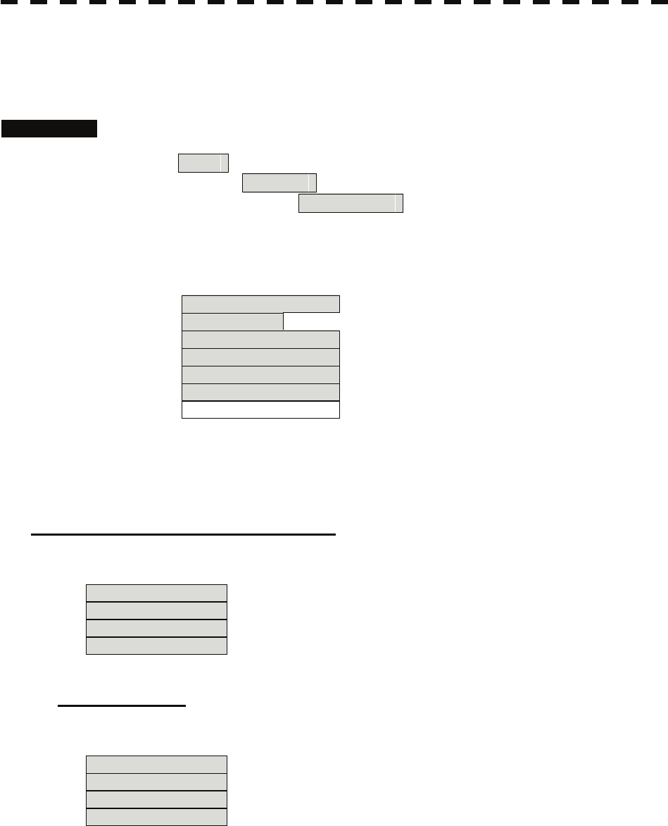
8-7
8.3.1 Check Performance on Test Menu
The radar operating state can be checked by opening the Test Menu.
Procedures 1. Perform the following menu open procedure to open the Test Menu.
Main
→ 9. NEXT
→ 9. Test Menu
2. Select the items to be checked.
The list of check items will appear.
1. Self Test [I] Self-diagnostic function
2. Monitor Test [II] Monitor check
3. Keyboard Test [III] Operation unit check
4. MON Display [IV] Performance monitor
5. System Alarm Log [V] Error log display
6. System Information [VI] System information display
Magnetron Current [VII] Indication of magnetron current
3. Select the items to be checked.
The list of check items will appear.
[I] Self-diagnosis function (Self Test)
Check of memory, scanner unit, and communications Lines
1. Memory Test [1] Memory check
2. TXRX Test [2] Scanner check
3. Line Test [3] Communication line check
4. Supply Voltage [4] Supply voltage check
[1] Memory Test
Checks for the performance of built-in memory.
1. SDRAM [1] SDRAM check
2. SRAM [2] SRAM check
3. FLASH ROM [3] Flash ROM check
4. GRAPHIC [4] Graphic check
When no abnormality is found, OK is displayed.
When an abnormality is found, NG is displayed.

8-8
8.3 Performance Check yyyy
yyyy
8
[2] TXRX Test
Checks for signals from the scanner.
Safety Switch Scanner’s safety switch check
AZI Pulse Scanner rotation signal check
HL Pulse Heading line signal check
MH Current Check on the load current of high voltage in the modulator
Trigger Radar trigger signal check
Video Radar video check
When no abnormality is found, OK is displayed.
When an abnormality is found, NG is displayed.
In standby, ** will appear.
[3] Check of Communication Lines (Line Test)
Check the status of communications with options.
TXRX Check on connection with the transmitter-receiver
SIG.PROC Check on connection with the signal processing circuit
TT Check on connection with the target tracking unit
GYROO I/F Check on connection with the GYRO I/F unit
GPS Compass Check on connection with the GPS compass
ISW Check on connection with the interswitch
Plotter Key Check on connection with the plotter option
When no abnormality is found, OK is displayed.
When an abnormality is found, NG is displayed.
The status display field of equipment not connected is left blank.
[4] Supply Voltage
Check the voltage of internal power supply.
Item Normal value
12V 11.00-12.20 V
5V 4.75-5.25 V
3.3V 3.14-3.46 V
Battery 2.50V or more
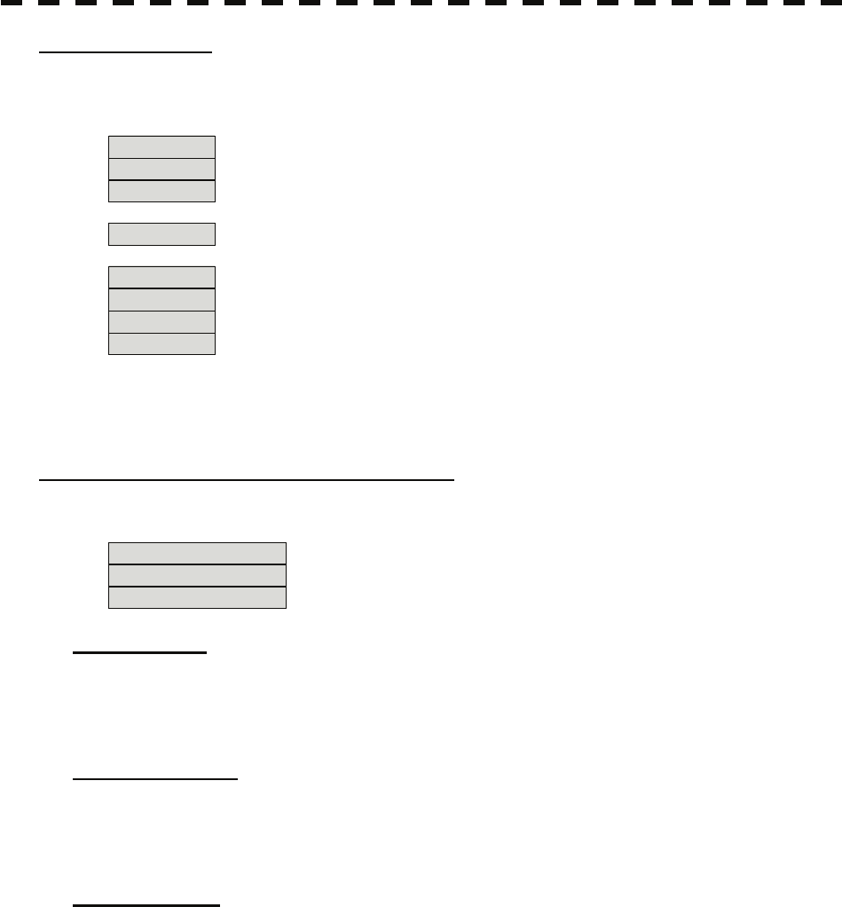
8-9
[II] Monitor Test
Checks for the display.
The test pattern will be shown on the display.
Pattern 1 All colors are filled with white.
Pattern 2 A white box is displayed on the black background of 1280 × 1024 dots.
Pattern 3 Displays rectangle × 2, circle × 2, and cross-shape× 13 (white lines on
the black background).
Pattern 4 Displays “H” of 9 dots × 9 dots on the entire screen (white character on
the black background).
Pattern 5 Gray scale display (16 levels)
Pattern 6 Displays a color bar.
Pattern 7 Displays the VDR test pattern.
Pattern 8 Displays the specified color.
To return to the normal display, press any key.
If errors occur in the monitor, no test pattern will appear.
[III] Keyboard Test (Operation Unit Test)
Checks for the controls and switches of the operation panel.
1. Key Test [1] Key check
2. Buzzer Test [2] Buzzer check
3. Light [3] Control panel light check
[1] Key Test
Checks for the controls and switches of the operation panel.
Each key on the operation panel on the display is shown in reverse video at the same time the key is
pressed, and the name of the pressed key is displayed.
[2] Buzzer Test
Checks for the operation panel buzzer.
The buzzer will sound.
The buzzer automatically stops after it sounds for a specified length of time.
[3] Light Test
Checks for the control panel light.
The brightness of the operation panel is gradually intensified at four levels.
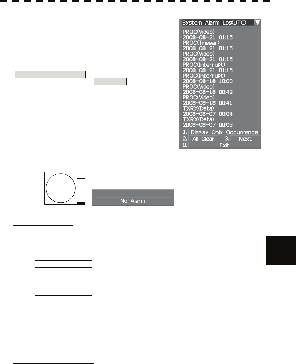
8-10
8.3 Performance Check yyyy
yyyy
8
[V] System Alarm Log display
Displays previously occurred system alarms with the dates and times
when they occurred.
The Alarm log display button (2-29P Alarm) is clicked, in the same
way as that one.
To display the occurrence alarm , press the
1. Display Only Occurrence button.
To erase the alarm logs, press the 2. All Clear button.
The current alarm is displayed at the lower right of the radar display. For details, refer to Chapter 9.
[VI] System INFO
Displays the current system information.
Indicator Processor software version information
TXRX Scanner software version information
System No. System number
TX Time Total magnetron transmitting time (Total time during which
radar was transmitted)
X-Band
S-Band
Motor Time The Motor Time function is unavailable in The JMA-5352-9R
and JMA-5362-8R. “0 hours” is always displayed.
TXRX Total Time Total operating time of the scanner unit (Total power-on time of
the antenna unit)
Total Time Total operating time of the display unit (Total power-on time of
the display unit)
JMA-5352-9R and JMA-5362-8R not display “Motor Time”.
[VII] Magnetron Current
Displays the Magnetron Current bar indicating the magnetron current to check.
When a 48 NM range is set, the magnetron current is normal if the Magnetron Current bar reads the value
below.
JMA-5352-9R 50 kW: 2-4 scale marks
JMA-5362-8R 60 kW: 4-6 scale marks
8-11
8.4 REPLACEMENT OF MAJOR PARTS
The system includes parts that need periodic replacement. The parts should be replaced as scheduled.
Use of parts over their service life can cause a system failure.
WARNING
Direct exposure to electromagnetic waves at close range
will have adverse effects on the human body. When it is
necessary to get close to the scanner for maintenance or
inspection purposes, make sure to turn the indicator power
switch to "OFF" or "STBY."
Direct exposure to electromagnetic waves at close range
will have adverse effects on the human body.
When conducting maintenance work, make sure to turn off
the power and unplug the power connector J1 of the radar
process unit so that the power supply to the equipment is
completely cut off.
Some equipment components can carry electrical current
even after the power switch is turned off, and conducting
maintenance work without unplugging the power connector
may result in electrocution, equipment failure, or accidents.
CAUTION
Make sure to shut off the main power before replacing
parts. Failure to comply may result in electrocution or
equipment failure.
When replacing magnetrons, make sure to shut off the main
power and let the equipment stand for more than 5 minutes
to discharge the high-voltage circuit. Failure to comply
may result in electrocution.
8-12
8.4 Replacement of Major Parts yyyy
yyyy
8
CAUTION
Make sure to take off your watch when your hand must get
close to the magnetron.
Failure to comply may result in damage to the watch since
the magnetron is a strong magnet.
Make sure that two or more staff member work together
when replacing the LCD. If only one person attempts to
replace the LCD, he/she may drop it and become injured.
Do not directly touch the inverter circuit of the LCD display
with a bare hand since high voltage temporarily remains in
the circuit even after the main power is shut off.
Failure to comply may result in electrocution.
8.4.1 Parts Required for Periodic Replacement
Here are parts required for periodic replacement
Part name Interval Radar model Part type Part code
JMA-5352-9R 2J55i 5VMAA00113
1. Magnetron 4000 hours JMA-5362-8R M1461i 5VMAA00108
JMA-5352-9R MPEM30217* MPEM30217*
2. Motor 10000 hours JMA-5362-8R MPEM00259B* MPEM00259B*
B201 109L0924H402 5BFAB00422
B103 JMA-5352-9R 9G1224H102 5BFAB00532
3. Fan (Scanner Unit)
B201
20000 hours
JMA-5362-8R 9G1224H102 5BFAB00532
4. Fan (power Unit) 20000 hours 109P0424H302 5BFAB00194
5. LCD PANEL 50000 hours H-CML-771 H-CML-771
6. Monitor fan 20000 hours H-CBP-173A H-CBP-173A
7. Fan (Radar Process Unit) 20000 hours H-7BFRD0005* H-7BFRD0005*
8. Backup battery 5 years CR2032 5ZBCJ00012
"*" means revision, such as A, B and so on.
i Use a genuine magnetron.

8-13
8.4.2 Replacement of Magnetron
Caution: Replacement of magnetron must be made by specialized service personnel.
For details, refer to Service Manual.
Use genuine parts as mentioned above.
When mounting a new magnetron, do not touch the magnet with a screwdriver or put it on an iron plate.
After replacement, connect the lead wire correctly.
Handling of Magnetron under Long-Time Storage
The magnetron that has been kept in storage for a long time may cause sparks and operate unstably when its
operation is started. Perform the aging in the following procedures:
(1) Warm up the cathode for a longer time than usually. (20 to 30 minutes in the STBY state.)
(2) Start the operation from the short pulse range and shift it gradually to the longer pulse ranges. If the
operation becomes unstable during this process, return it to the standby mode immediately. Keep the
state for 5 to 10 minutes until the operation is restarted.
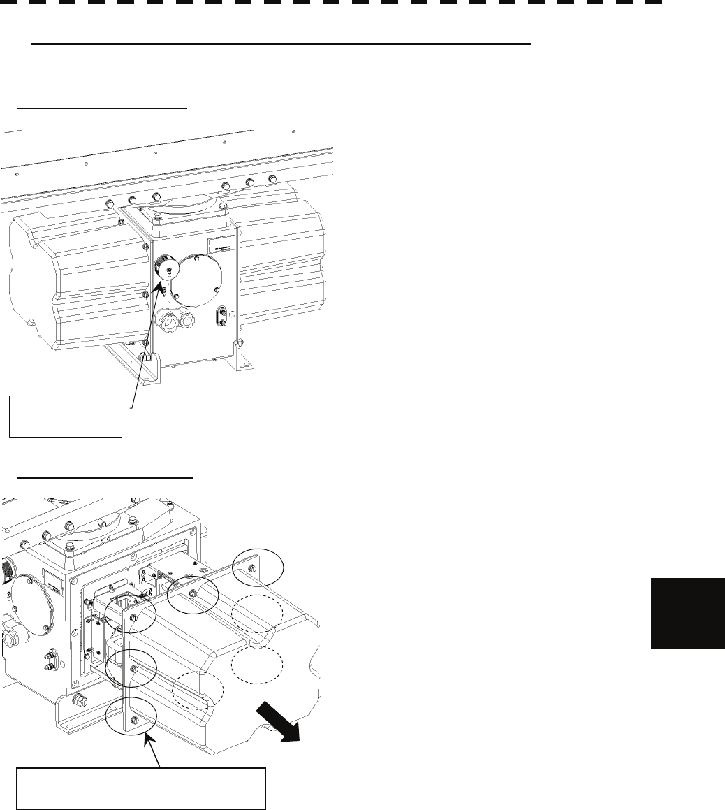
8-14
8.4 Replacement of Major Parts yyyy
yyyy
8
Magnetron Replacement Procedure for Scanner Unit NKE-1064
Before starting part replacement work, turn off the safety switch of the scanner unit.
1) Turn off the safety switch.
The safety switch is located on the rear (stern) side
of the scanner unit. Remove the cover and turn off
(to the lower side) the safety switch.
2) Remove the pedestal cover.
The magnetron is located at the right (starboard) side.
Remove the left side cover.
The cover is fixed with 6 (M8) hexagonal screws.
Put the remove cover to safety place, and be careful
that there is foreign matter or dust adhered to the
gasket.
Safety switch
Remove the eight (M8) hexagonal bolts.
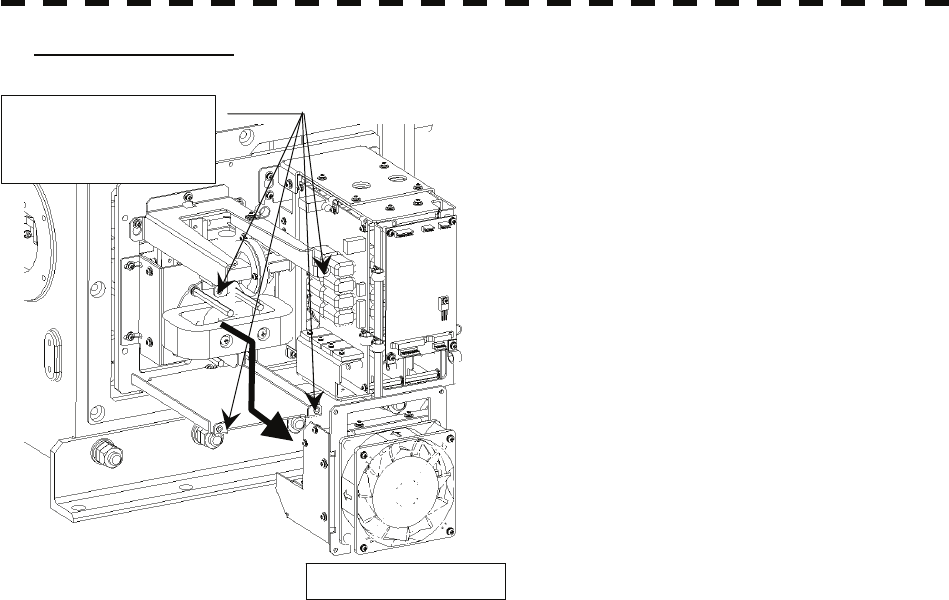
8-15
3) Remove the fan unit.
The magnetron is located behind the fan unit.
After removing the four (M4X10) screws then
remove the fan unit.
Be careful not to lose any of the removed
screws.
Remove the four (M4)
screws.
The fan unit
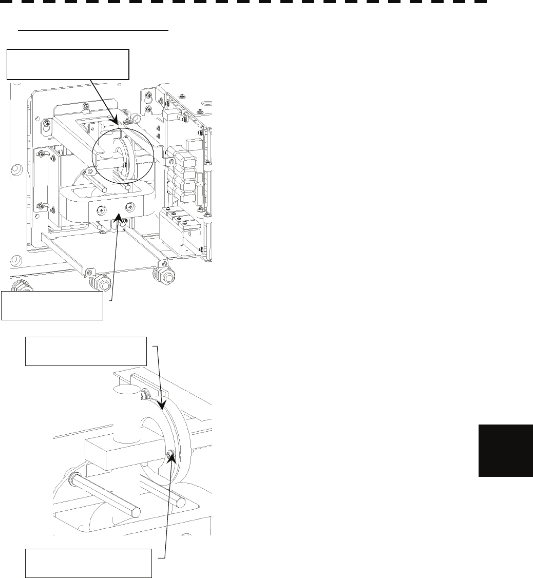
8-16
8.4 Replacement of Major Parts yyyy
yyyy
8
4-1) Remove the attachment plate.
The place of attachment between the magnetron and
microwave circuits is fixed with the attachment plate so that
there is no gap.
To remove the magnetron unit, the attachment plate needs to
be removed at first.
After removing two (M4X10) screws holding the attachment
plate in place then remove the attachment plate.
The attachment plate
Remove the two screws.
Magnetron unit
The place of attachment
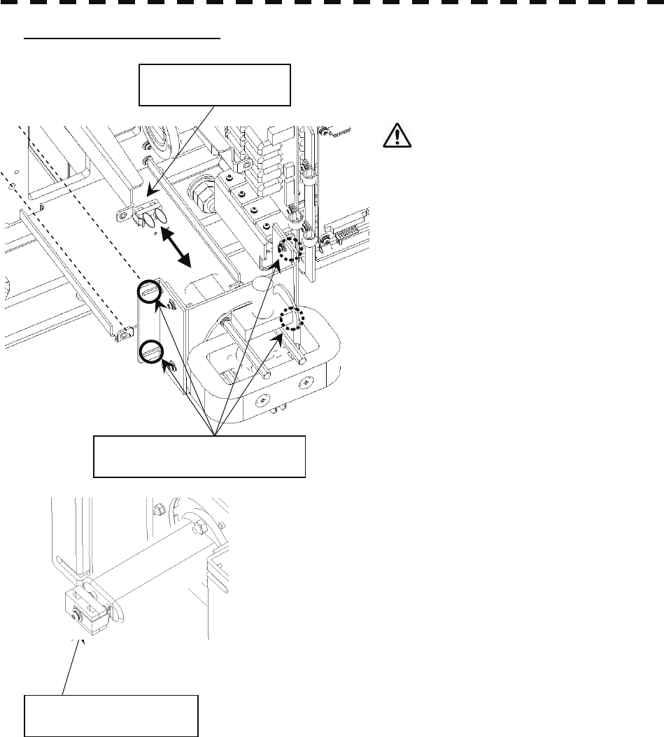
8-17
4-2) Remove the magnetron unit.
Remove four (M4) screws holding the
magnetron unit in place and magnetron socket
and then remove the unit.
Be careful not to cut the cable of
magnetron socket.
Remove the four (M4) screws.
The magnetron socket
The magnetron socket
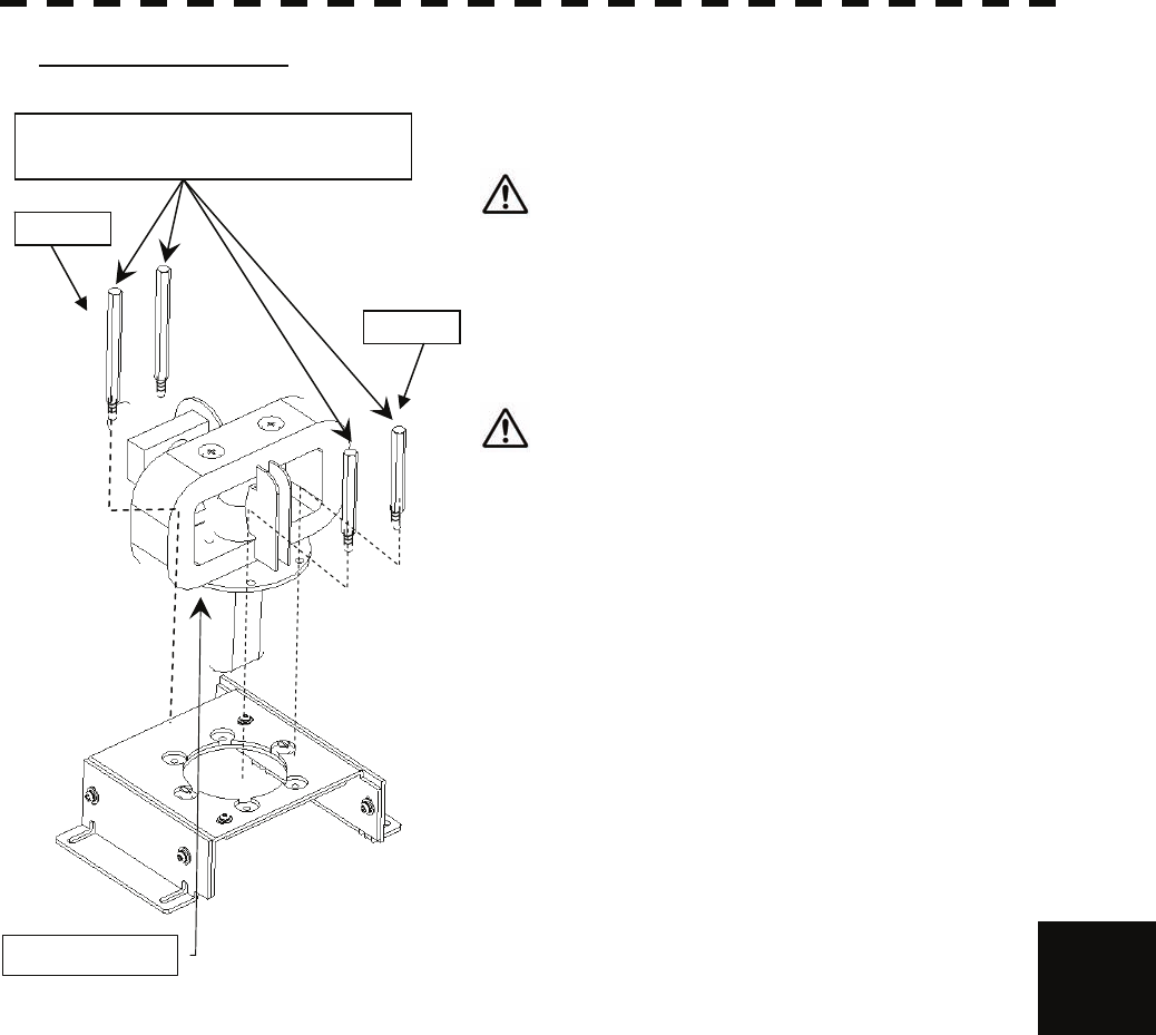
8-18
8.4 Replacement of Major Parts yyyy
yyyy
8
5) Replace the magnetron.
Remove the four hexagonal bolts holding the magnetron in
place and then replace the magnetron.
Use an anti-magnetic screwdriver because the contact
of the metal tool with the magnetron causes deterioration of
its performance.
Reconnect the magnetron socket to new magnetron.
After having replaced the magnetron, reassemble the unit by
following the disassembly procedure in the reverse order.
Pay attention not to make a gap between magnetron
and microwave circuits, not to forget to tighten the screws
and bolts and to connect the cables.
Install the new magnetron together with the fixture and tighten the screws to hold the cables.
Follow the removal procedure in the reverse order.
Do not forget to tighten the screws and connect the cables.
long
short
Magnetron
Remove the four (M4) hexagonal bolts.
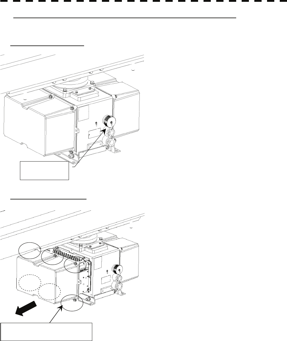
8-19
Magnetron Replacement Procedure for Scanner Unit NKE-3710-8
Before starting part replacement work, turn off the safety switch of the scanner unit.
1) Turn off the safety switch.
The safety switch is located on the rear (stern) side
of the scanner unit. Remove the cover and turn off
(to the lower side) the safety switch.
2) Remove the pedestal cover.
The magnetron is located at the left (port) side.
Remove the left side cover.
The cover is fixed with 6 (M8) hexagonal screws.
Put the removed cover to safety place, and be careful
that there is no foreign matter or dust adhered to the
gasket.
Safety switch
Remove the six hexagonal bolts.
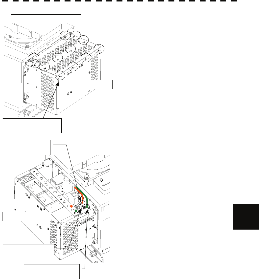
8-20
8.4 Replacement of Major Parts yyyy
yyyy
8
3) Remove the magnetron cables.
The magnetron is located behind the modulator unit.
Loosen the 12 screws holding the cover in place, and
remove the cover.
Remove the magnetron cables (yellow and green)
connected to pulse transformer.
Be careful not to lose any of the removed screws.
Magnetron cable
(
Green
)
The modulator unit
Magnetron cable
(
Yellow
)
Pulse transformer
The modulator unit
Remove the 12 screws
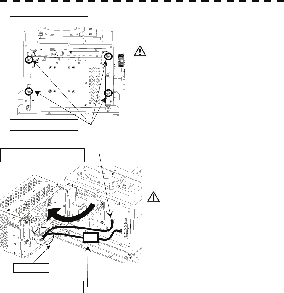
8-21
4) Remove the modulator unit.
Loosen the four (M6) screws holding the modulator unit in
place, and open it.
The left side of the modulator unit is made by hinge
structure.
After open the modulator unit and remove P/J201
and P/J202 connector, push it up and remove it.
Put the removed unit on safety place.
Extreme care should be taken to connect the
P/J201 and P/J202 for prevention of contact with the
magnetron or the pulse transformer.
Remove the 4 screws
Remove P/J202 connector
Remove P/J201 connector
Wire band

8-22
8.4 Replacement of Major Parts yyyy
yyyy
8
5) Replace the magnetron.
Remove the 10 screws (M6X20) holding the
magnetron in place then replace the magnetron.
Use an anti-magnetic screwdriver because
the contact of the metal tool with the
magnetron causes deterioration of its
performance.
After having replaced the magnetron,
reassemble the unit by following the
disassembly procedure in the reverse order.
Do not forget to tighten the screws and connect
the cables.
Remove the 10 screws
Magnetron

8-23
z When replacing the LCD monitor, which is easily
broken by a little impact, handle it carefully and do not
hit any article against it or put it on a hard article.
8.4.3 Replacement of LCD Monitor
Caution: Replacement of LCD Monitor must be made by specialized service personnel.
For details, refer to Field Service Manual.
(1) Disconnect the cables from the connectors “VIDEO” and “VIDEO DC OUT” on the rear of the
processor.
(2) Softly place the LCD monitor on a desk covered with a soft cloth.
(3) Attach a new LCD monitor in the reverse sequence as described above.
Attention

8-24
8.4 Replacement of Major Parts yyyy
yyyy
8
8.4.4 Replacement of Backup Battery
Caution: Replacement of backup battery must be made by specialized service personnel.
For details, refer to Service Manual.
A coin-cell battery maintains radar system configuration, date, and time information while power off
condition. radar system configuration is saving to non-volatile memory at fixed intervals.
About the Battery Alarm
If Battery Low is appeared at the lower-right of the display when start up the radar system, the battery
has not enough time left to live. We recommend to replace the battery.
If Battery Dead is appeared at the lower-right of the display when start up the radar system,
the battery has no time left to live. There is a necessary to replace the battery. In This condition, this
radar system is restored configuration information from flash memory and normal operation is available.
However, you turned of the radar system before saving to flash memory, the configuration information is
maybe lost. In this case, you must setup the configuration again.
Note: About disposal of used battery, refer to Section 10.2.
How to Replacement of Backup Battery
1. Remove the Coin-Cell Battery from the Holder
Be careful, don't break holder.
3. Fix the Coin-Cell Battery in the Holder
Turn up + surface.
Battery type : CR2032

SECTION 9
TROUBLESHOOTING AND
AFTER-SALES SERVICE
9.1 FAULT FINDING.................................................................................. 9-1
9.2 TROUBLE SHOOTING....................................................................... 9-7
9.3 AFTER-SALES SERVICE..................................................................9-11
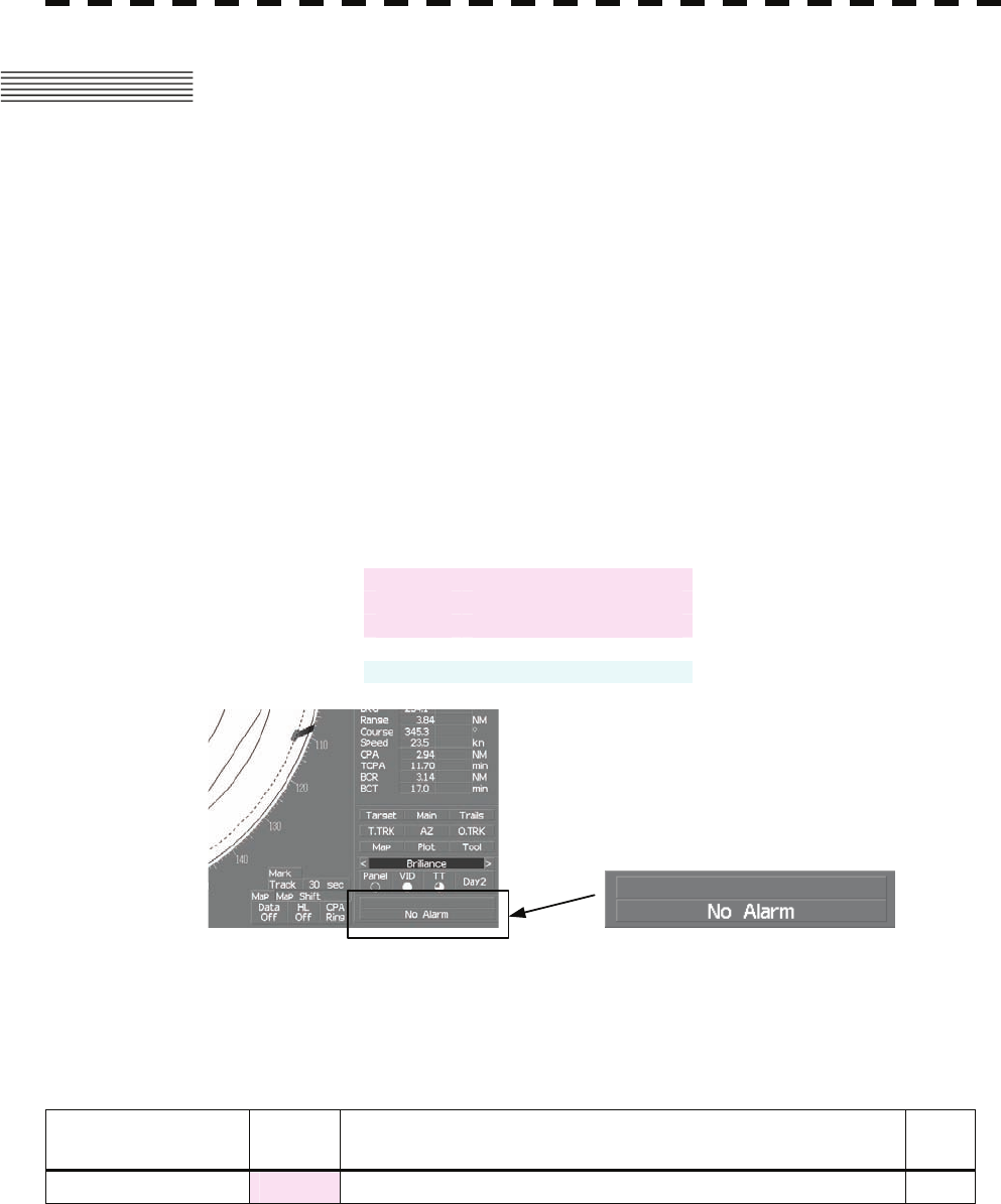
9-1
9.1 FAULT FINDING
In case of semiconductor circuits, it is deemed that there are few cases in which the used
semiconductor devices have inferior quality or performance deterioration except due to
insufficient design or inspection or by other external and artificial causes. In general, the
relatively many causes are disconnection in a high-value resistor due to moisture, a defective
variable resistor and poor contact of a switch or relay.
Some troubles are caused by defective parts, imperfect adjustment (such as tuning adjustment)
or insufficient service (such as poor cable contact). It will also be effective to check and
readjust these points.
9.1.1 List of Alarms and other Indications
If any of the following alarm occurs, the system displays the alarm message in red in order to
attract the attention of operator. Other messages are displayed with the suitable color which is
yellow or blue depending on the level of message importance.
Alarm :Red :Collision-related Alarm
:Navigation Alarm
:System Alarm
Warning :Yellow :System Warning
Information :Blue :Operation Information
Alarm message is displayed in the lower right of the display. For operation details refer to
page2-29 Alarm.
Table 9-1 Critical Alarm
Message Class Description ALR
No.
CPA/TCPA Alarm There is a dangerous target. 301
ALR No : Unique alarm number in ALR sentence and ACK sentence.

9-2
9.1 Fault Finding
y
yyyy
yyyy
9
Table 9-2 List of System Alarm Message
Message Class Description ALR
No.
Autopilot (Data) Alarm Autopilot: No communication or data error. 101
Current (Data) Alarm Tidal current: No communication or data error. 119
Date (Data) Alarm Date data: No communication or data error. 112
Datum (Data) Alarm DTM: No communication or data error. 122
Depth (Data) Alarm Water depth: No communication or data error. 115
Fan (LCD) Alarm LCD monitor: Fan error. 955
GPS (Status) Alarm GPS status error. 103
GYRO I/F (Data) Alarm GYRO I/F: No communication or checksum error. 324
GYRO I/F (GYRO) Alarm GYRO I/F: GYRO error detected. 110
GYRO I/F (Log) Alarm GYRO I/F: Log error detected. 111
Heading (Data) Alarm Heading data: No communication or data error. 113
Keyboard (Data) Alarm Operation unit: Communication error or checksum error. 325
Keyboard2 (Data) Alarm Second operation unit: Communication error or checksum error. 325
Out of Bounds Alarm Own ship's latitude is over 85°N or 85°S. 123
Position (Data) Alarm Latitude / longitude data: No communication or data error. 102
PROC (AZI) Alarm Process unit: AZI error. 305
PROC (HL) Alarm Process unit: HL error. 306
PROC (Interrupt) Alarm Process unit: Interrupt error. 962
PROC (Trigger) Alarm Process unit: Trigger error. 304
PROC (Video) Alarm Process unit: VIDEO error. 303
ROT (Data) Alarm Rate of Turn: No communication or data error. 120
RSA (Data) Alarm Rudder Sensor Angle: No communication or data error. 121
Speed (2AXG) Alarm 2-axis log (speed over ground): No communication or data error. 114
Speed (2AXW) Alarm 2-axis log (speed over water): No communication or data error. 114
Speed (GPS) Alarm GPS speed: No communication or data error. 114
Speed (Log) Alarm 1-axis log: No communication or data error. 114
SRB (Data) Alarm SRB: No communication or data error. 960
TEMP (Data) Alarm Water temperature: No communication or data error. 117
TXRX (AZI) Alarm Scanner: BP error. 311
TXRX (Data) Alarm Scanner: No communication, communication mismatched,
checksum error, or collision. 326
TXRX (Fan 1) Alarm Power Unit: FAN error. 320
TXRX (HL) Alarm Scanner: HL error. 312
TXRX (MHV) Alarm Scanner: Modulator’s high voltage alarm. 315
TXRX (Reverse) Alarm Scanner: Reverse rotation. 313
TXRX (SSW Off) Alarm Scanner: Safety switch OFF. 308
TXRX (Trigger) Alarm Scanner: TRIGGER error.. 310
TXRX (Video) Alarm Scanner: VIDEO error. 309
Wind (Data) Alarm Wind direction/velocity: No communication or data error. 118
ALR No : Unique alarm number in ALR sentence and ACK sentence.
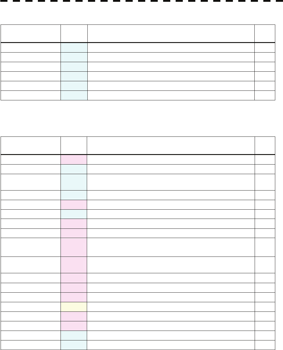
9-3
Table 9-3 List of Notification
Message Class Description ALR
No.
CCRP Changed INFO CCRP is automatically changed.
Copying INFO Displayed-image is capturing to file.
POSN Reset INFO Change the latitude and longitude sentence.
Set GYRO INFO Requires setting of true bearing.
TM Reset INFO Resetting TM in a short time.
Weather INFO INFO Weather information is received.
ALR No : Unique alarm number in ALR sentence and ACK sentence.
Table 9-4 List of RADAR Alarm, Target Tracking Alarms and AIS Function Alarms
Message Class Description ALR
No.
AIS (Data) Alarm AIS: No communication or communication error. 116
AIS 95% Capacity INFO Over 95% of the maximum number of AIS targets.
AIS ACT 95%
Capacity INFO Over 95% of the maximum number of AIS targets to be activated.
AIS ACT MAX INFO Maximum number of AIS targets to be activated.
AIS Alarm *** Alarm AIS alarm (Up to 10 alarm messages can be displayed.).
AIS MAX Target INFO Maximum number of AIS targets.
AIS PROC (Data) Alarm AIS processing circuit: No communication or communication error. 328
CPA/TCPA Alarm There is a dangerous target. 301
Lost Alarm Failure in tracking the target that has been under tracking.
Failure in receiving AIS target data for a specified time.
New Target Alarm Acquisition or activation of a target in the automatic acquisition /
activation zone. 302
RADAR Alarm (In) Alarm Targets have entered the radar alarm range.
RADAR Alarm (Out) Alarm Targets have left the radar alarm range.
REF Target Alarm Decrease in the reference target accuracy.
Trial Warning There is a dangerous target, when trial maneuver is active.
TT (Boot) Alarm Target tracking unit start failure. 344
TT (Data) Alarm The target tracking unit is malfunctioning.. 323
TT 95% Capacity INFO Over 95% of the maximum number of targets to be tracked.
TT MAX Target INFO The maximum number of targets is under acquisition.
ALR No : Unique alarm number in ALR sentence and ACK sentence.
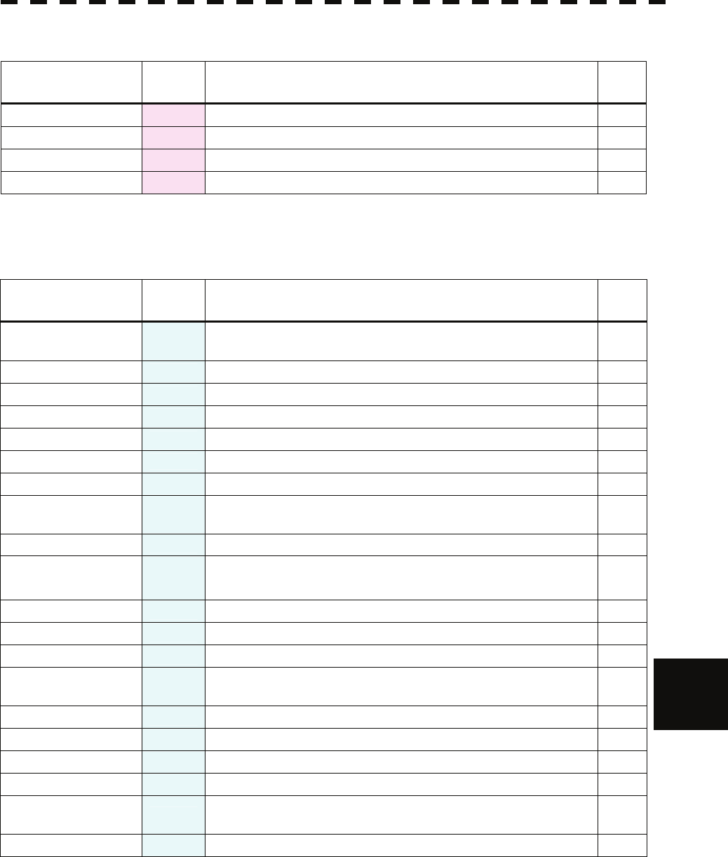
9-4
9.1 Fault Finding
y
yyyy
yyyy
9
Table 9-5 List of Route Error Messages and Warnings
Message Class Description ALR
No.
Approach Alarm Approach the route.
Arrival Alarm Arrive at way point.
Break Off (WPT) Alarm Out of the way point.
Cross Track Error Alarm Go off the route.
ALR No : Unique alarm number in ALR sentence and ACK sentence.
Table 9-6 List of Operational Error Messages and Warnings
Message Class Description ALR
No.
Can’t Transmit INFO Tried to transmit within 5 second after standby or when the
transmitter-receiver has any trouble.
Card Full INFO Card : Run out of free space.
Copy Failed INFO Card : Copy failure.
Delete failed INFO Card : Deletion failure.
Format Card INFO Card : Unformatted card.
Format Failed INFO Card : Format failure.
Invalid Card INFO Card : Invalid card.
Invalid Connection INFO The operator set performance monitor to on without selecting
straight.
Invalid Data INFO Tried to enter any data beyond its range.
Invalid Range INFO TM selection due to TM-disabled range (96 nm).
Zooming in a ZOOM-disabled range (0.125 nm).
MAX Point INFO Tried to enter navigation information beyond the specified.
No Card INFO Card not detected yet.
No Position Data INFO Mark or line input when the latitude and longitude is invalid.
No Heading Data INFO Target tracking operation or TM selection when bearing data is
invalid.
No Object INFO No object at the cursor-specified position.
Not Allowed INFO General operation error.
Out of Range INFO Out of operation range.
Read Failed INFO Card : Read failure.
Slave Mode INFO Operation of a menu for the scanner unit when the slave mode is
active.
Write Failed INFO Card : Write failure.
ALR No : Unique alarm number in ALR sentence and ACK sentence.
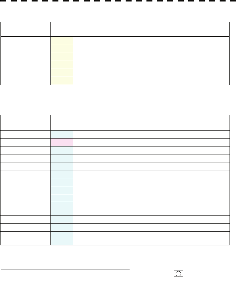
9-5
Table 9-7 List of Conditions Messages
Message Class Description ALR
No.
Battery Dead Warning The battery is dead.
Battery Low Warning The battery is weakening.
GPS (HDOP) Warning The HDOP level is increased (Decrease in the GPS accuracy.).
MON Test Warning Performance monitor is active.
No Battery Warning The battery had removed.
Scanner Rotating Warning The scanner is rotating (When transmitter is standby state.).
ALR No : Unique alarm number in ALR sentence and ACK sentence.
Table 9-8 List of Interswitch Alarms and Messages
Message Class Description ALR
No.
Connection Masked INFO Inhibition of control / connection is set.
ISW (Data) Alarm ISW: No communication, data mismatched, or checksum error. 327
ISW Busy INFO Access to the ISW menu was made during interswitching.
ISW Complete INFO The switchover of the Interswitch ended normally.
ISW Error INFO The interswitch is disabled.
TXRX Standby INFO The scanner unit is in the standby mode.
ISW Straight INFO The interswitch is forced to change the connection into straight.
ISW Standby INFO The Interswitch recovered normally.
ISW Time Out INFO Failed in switching.
Master Range CHG INFO The range of the own display unit has changed due to change in
the range of the master display unit.
Master Standby INFO The master display unit does not transmit any signals.
Pattern CHG Failed INFO Connection change failed.
Update ISW Software INFO Tried to enter new TXRX function, when interswitch software
used old version.
ALR No : Unique alarm number in ALR sentence and ACK sentence.
Message set off in a failure of the monitor fan
!
When a failure has occurred in the monitor fan, the LCD monitor displays LCD FAN FAILURE at the center.
This display will disappear by pressing the BRIGHTNESS knob on the LCD monitor. In order to replace the
monitor fan, contact our service department, or the distributor.
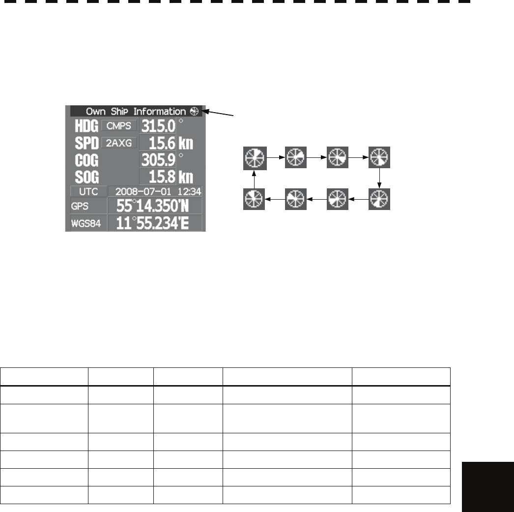
9-6
9.1 Fault Finding
y
yyyy
yyyy
9
9.1.2 Operation Checking
When the system is operating, the operation status (located at the upper right of the screen) is
changing pictures.
If picture freeze occurred, turn off the system and restart the system.
Operation status
9.1.3 Fuse Checking
Melted fuses are caused by any clear cause. When a fuse is replaced, it is necessary to check the
related circuits even if there is no trouble. In checking, note that there is some dispersion in the
fusing characteristics. Table 9-9 shows a list of fuses used in the equipment.
Table 9-9 Fuse List
Location Parts No. Current Rating Protection Circuit Type
Power unit F601 to F602 3.15A Power unit NBL-315 MF60NR 250V 3.15
Power unit F603 to F605 7A Scanner unit (drive part)
NKE-1064/3710-8 MF61-TS7
Power unit F1 5A AVR circuit PC620 MF60NR 250V 5
Scanner F1 1A Power supply circuit PC230 MF51NR 250V 1
Display Unit F2 to F3 10A I/O circuit PC410 MF60NR 250V 10
GYRO I/F unit F1 to F4 0.5A GYRO I/F circuit PC4201 MF51NR 250V 0.5

9-7
9.2 TROUBLE SHOOTING
As this radar equipment includes complicated circuits, it is necessary to request a specialist engineer for repair or
instructions for remedy if any circuit is defective.
There are also troubles by the following causes, which should be referred to in checking or repair work.
1 Poor Contact in Terminal Board of Inter-Unit Cables
a) Poor contact in terminal board
b) The cable end is not fully connected, that it, contacted with earthed another terminal.
c) Disconnected cable wire
2 Poor Contact of Connector within Unit
Reference: This radar equipment is provided with 9-10 standard spares.
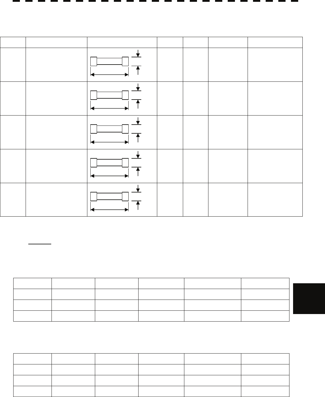
9-8
9.2 Trouble Shooting
y
yyyy
yyyy
9
Table 9-10 Spares (7ZXRD0021, JMA-5352-9R, JMA-5362-8R)
7ZXRD0021
Name Type/Code Shape (mm) In use Spare Parts No. Location
Fuse MF60NR 250V 3.15
(5ZFGD00207)
2 6 F601 to F602 Inside
power unit
Fuse MF61-TS7
(5ZFAA00084)
3 9 F603 to F605 Inside
power unit
Fuse MF60NR 250V 5
(5ZFGD00208)
1 3 F1
Power unit
AVR circuit
Fuse MF51NR 250V 1
(5ZFGD00199)
1 3 F1
Scanner
power supply circuit
Fuse MF60NR 250V 10
(5ZFGD00017)
2 6 F2~F3
Inside
radar process unit
Caution: Use the specified magnetron in table 9-11.
Table 9-11 Special Parts
[I] JMA-5352-9R
Parts No. Name Type Manufacturer Location Code
V101 Magnetron 2J55 NJRC Scanner 5VMAA00113
A101 Circulator NJC3901RJ NJRC Scanner 5AJBV00003
A102 TRHPL TL393 NJRC Scanner 5VLAA00029
[II] JMA-5362-8R
Parts No. Name Type Manufacturer Location Code
V101 Magnetron M1461 NJRC Scanner 5VMAA00108
A101 Circulator NJC-3314 NJRC Scanner NJC-3314
A102 TRHPL TL378A NJRC Scanner 5VLAA00037
30
Φ6.4
20
Φ5.2
30
Φ6
32
Φ6.4
30
Φ6.4

9-9
Table 9-12 Circuit Block to be Repaired (JMA-5352-9R)
Location Circuit Block Type Remarks
Scanner Modulator unit NMA-486-V
Magnetron, Pulse transformer
not included
CPA-209A, CCB-542 included
Scanner Modulator circuit CPA-209A
Scanner PW control circuit CCB-542
Scanner Receiver unit NRG-210A
Scanner I/F circuit CMH-1658
Scanner Power supply circuit CBA-170
Scanner Magnetron 2J55
Scanner Motor MPEM30217*
Scanner Encoder NOY-2048-2MC
Scanner Fan (B201) 109L0924H402
Scanner Fan (B103) 9G1224H102
Power unit AVR circuit CBA-204B
Power unit Interface circuit CMH-2081
Power unit T/R control circuit CMC-1205V
Power unit Fan 109P0424H302
Process unit Radar process circuit CDC-1332
Process unit ARPA process unit NCA-877WA Option
Process unit ATA process unit NCA-877A Option
Process unit AIS process unit NQA-2103 Option
Process unit GYRO interface circuit CMJ-304E
Process unit Terminal board CQD-1937A
Process unit I/F unit NQA-2123
Process unit Power supply unit NBD-818A
Process unit Fan 7BFRD0005*
Operation unit Operation circuit CCK-979
Operation unit I/F circuit CQC-1204
Operation unit Trackball CCK-1000
LCD Monitor Bezel kit MPBC43590* for radar
LCD Monitor Brower circuit H-CBP-173A
LCD Monitor I/F circuit H-CMH-2227
LCD Monitor Inverter circuit H-CBF-38
LCD Monitor Brilliance control circuit H-CCK-989
LCD Monitor 19Inch LCD H-CML-771
"*" means revision, such as A, B and so on.

9-10
9.2 Trouble Shooting
y
yyyy
yyyy
9
Table 9-13 Circuit Block to be Repaired (JMA-5362-8R)
Location Circuit Block Type Remarks
Scanner Modulator unit NMA-195A
Magnetron not included
CPA-209A, CCB-542 included
Scanner Modulator circuit CPA-209A
Scanner PW control circuit CCB-542
Scanner Receiver unit NRG-213A W103, W104 included
Scanner I/F circuit CMH-1658
Scanner Power supply circuit CBA-170
Scanner Magnetron M1461
Scanner Motor MPEM00259B*
Scanner Encoder NOY-2048-2MC
Scanner Fan (B201) 9G1224H102
Power unit AVR circuit CBA-204B
Power unit Interface circuit CMH-2081
Power unit T/R control circuit CMC-1205V
Power unit Fan 109P0424H302
Process unit Radar process circuit CDC-1332
Process unit ARPA process unit NCA-877WA Option
Process unit ATA process unit NCA-877A Option
Process unit AIS process unit NQA-2103 Option
Process unit GYRO interface circuit CMJ-304E
Process unit Terminal board CQD-1937A
Process unit I/F unit NQA-2123
Process unit Power supply unit NBD-818A
Process unit Fan 7BFRD0005*
Operation unit Operation circuit CCK-979
Operation unit I/F circuit CQC-1204
Operation unit Trackball CCK-1000
LCD Monitor Bezel kit MPBC43590* for radar
LCD Monitor Brower circuit H-CBP-173A
LCD Monitor I/F circuit H-CMH-2227
LCD Monitor Inverter circuit H-CBF-38
LCD Monitor Brilliance control circuit H-CCK-989
LCD Monitor 19Inch LCD H-CML-771
"*" means revision, such as A, B and so on.

9-11
9.3 AFTER-SALES SERVICE
9.3.1 Keeping period of maintenance parts
Keeping period of maintenance parts is ten years from the production is discontinued.
9.3.2 When you Request for Repair
If you suppose the product may be out of order, read the description in Section 9 carefully and
check the suspected point again.
If it is still out of order, you are recommended to stop operation of the equipment and consult
with the dealer from whom you purchased the product, or our branch office in your country or
district, the sales department in our main office in Tokyo.
z Repair within the Warranty Period
If any failure occurs in the product during its normal operation in accordance with the
instruction manual, the dealer or JRC will repair free of charge. In case that any failure is
caused due to misuse, faulty operation, negligence or force major such as natural disaster
and fire, the product will be repaired with charges.
z Repair after the Warranty Period
If any defective function of the product is recoverable by repair, the repair of it will be
made at your own charge upon your request.
z Necessary Information for Repair
☆ Product name, model, manufacturing date and serial number
☆ Trouble conditions (as detailed as possible. Refer to “Radar Failure Check List” in
page 9-13.)
☆ Name of company/organization, address and telephone number
9.3.3 Recommended Maintenance
The performance of the product may deteriorate due to the secular change of the parts used in
it, though such deterioration depends upon the conditions of operation.
So checkup and maintenance is recommendable for the product in addition to your daily care.
For maintenance, consult with the near-by dealer or our sales department.
Such maintenance will be made with charges.
For further details of after-sale service, contact the JRC Offices.

9-12
9.3 After-sales Service
y
yyyy
yyyy
9
Radar Failure Check List
When placing an order for repair of the product, it is requested that you could confirm the check items and fill the
results and sent the sheet to our contact.
If there is any unclear items, contact the ship on which the product is installed, and give the correct information on
the product.
Ship name: Phone: Fax:
Radar general model name: JMA- Serial No. :
(Write the full model name correctly)
(1)Check the following items in the order of the number, and circle the applicable answer between YES or NO.
If the item cannot be determined as YES or NO, explain in detail in the item (18), others.
(2)If any of the items (1) to (5) is marked as NO, check the fuse of the product (refer to Section 9.1.2 and 9.2).
(3)Check the items (4) to (17) while the transmission (TX) is ON.
*Functions mentioned in the items (14), (15) and (17) may be optional, answer is not necessary.
No. Check Item Result
(1) Power can be turned on. (The lamp on the Operation unit is lit) YES NO
(2) A few minutes after powering-on, it will become standby status . YES NO
(3) When powering-on (or TX ON), LCD monitor something is lit. YES NO
(4) The antenna rotates at the transmission (TX) ON.
(Check the following items while transmission is ON) YES NO
(5) Current is supplied to the magnetron. (Refer to the instruction manual) YES NO
(6) Turning is enabled. (Check with the range of 6 NM or more) YES NO
(7) Fixed marker is displayed. YES NO
(8) VRM is displayed. YES NO
(9) While noise is displayed while set at SEA and RAIN minimum, GAIN maximum,
IR-OFF and range 48 NM. YES NO
(10) Target reflection echo is displayed. YES NO
(11) Sensitivity of reflection echo is normal. YES NO
(12) EBL is displayed. YES NO
(13) Cursor mark moves. YES NO
*(14) GYRO course can be set and normally displayed. YES NO
*(15) LOG speed can be normally displayed. YES NO
(16) Target tracking function works normally. YES NO
*(17) If equipped with an interswitch, when switching from the straight mode (II) to (X),
the failures (items marked NO) in the above (1) to (16), are switched over to the
other unit. YES NO
(18)Others (Error message, etc. )

SECTION 10
DISPOSAL
10.1 DISPOSAL OF THE UNIT............................................................... 10-1
10.2 DISPOSAL OF USED BATTERIES ................................................ 10-1
10.3 DISPOSAL OF USED MAGNETRON............................................. 10-2
10.4 DISPOSAL OF TR-TUBE................................................................ 10-2
10.5 ABOUT THE CHINA ROHS............................................................ 10-3
10─1
10.1 DISPOSAL OF THE UNIT
When disposing of this unit, be sure to follow the local laws and regulations for the place of
disposal.
10.2 DISPOSAL OF USED BATTERIES
WARNING
When disposing of used lithium batteries, be sure to
insulate the batteries by attaching a piece of adhesive tape
on the + and - terminals. Failure to comply may cause
heat generation, explosion, or fire when the batteries get
shorted out.
In this unit, Lithium batteries are used for the following parts:
Radar Processing circuit (CDC-1332): BT300 (Maxell: CR2032)
z Do not store used lithium batteries. Dispose of them in accordance with regulations of
local government.
z When disposing of used lithium batteries be sure to insulate the batteries by taping the +
and - terminals. For disposal of batteries, be sure to follow the local laws and regulations.
For detail, consult with the dealer you purchased the product our business office, or local
government.
10-2
10.3 Disposal of Used Magnetron
yy
yyyy
yyyy
10
10.3 DISPOSAL OF USED MAGNETRON
Magnetron is used in the Scanner (NKE-1064/3710-8)
z When the magnetron is replaced with a new one, return the used magnetron to our dealer
or business office.
For detail, consult with our dealer or business office.
10.4 DISPOSAL OF TR-TUBE
In the case that either mark shown in Fig.10.1 is on the expired TR-tube, Radioisotopes are in
the TR-tube
z Disposal of TR-tube with these marks must be done in accordance with the laws and
regulations of the pertaining country.
For detail, consult with our dealer or business office.
z Radiation from TR-tube has no effect on the human body.
z Don’t take apart TR-tube.
Fig.10.1
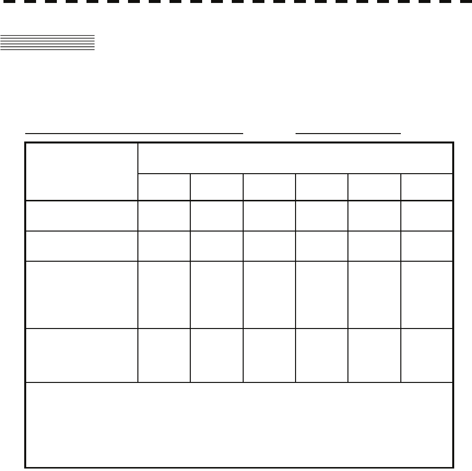
10─3
10.5 ABOUT THE CHINA ROHS
形式名(Type): JMA-5352-9R, JMA-5362-8R 名称(Name): RADAR
铅 汞 镉 六价铬 多溴联苯 多溴二苯醚
(Pb) (Hg) (Cd) (Cr6+) (PBB) (PBDE)
雷达天线单元
(Scanner Unit)
××××××
收发信单元
(Transmitter-receiver Unit)
××××××
主船内装置 (Inboard Unit)
・显示装置 (Display Unit)
・键盘装置 (OperationUnit)
・信号处理装置
(RADAR Process Unit)
××××××
外部设备 (Peripherals)
・选择 (Options)
・电线类 (Cables)
・手册 (Documennts)
××××××
有毒有害物质或元素的名称及含量
(Names & Content of toxic and hazardous substances or elements)
(Toxic and Hazardous Substances and Elements)
×:表示该有毒有害物质至少在该部件的某一均质材料中的含量超出SJ/T11363-2006 标准规定的限量要求。
(Indicates that this toxic or hazardous substance contained in at least one of the homogeneous materials
used for this part is above the limit requirement in SJ/T 11363-2006.)
○:表示该有毒有害物质在该部件所有均质材料中的含量均在SJ/T11306-2006 标准规定的限量要求以下。
(Indicates that this toxic, or hazardous substance contained in all of the homogeneous materials for this
part is below the requirement in SJ/T11363-2006.)
部件名称
(Part name)
有毒有害物质或元素

SECTION 11
SPECIFICATIONS
11.1 JMA-5352-9R, JMA-5362-8R TYPE RADAR................................ 11-1
11.2 SCANNER (NKE-1064) ................................................................. 11-2
11.3 SCANNER (NKE-3710-8).............................................................. 11-3
11.4 DISPLAY UNIT (NCD-4530) .......................................................... 11-4
11.5 PROCESSOR UNIT (NDC-1417) .................................................. 11-5
11.6 TARGET TRACKING FUNCTION (OPTION)................................ 11-7
11.7 AIS UNIT (NQA-2103) (OPTION).................................................. 11-8
11.8 PLOTTER ...................................................................................... 11-9
11.9 OPERATION UNIT (NCE-5171) .................................................. 11-10
11.10 AVAILABLE INPUT SIGNAL .......................................................11-11
11.11 AVAILABLE OUTPUT SIGNAL................................................... 11-12
11.12 STANDARD CONFIGURATION.................................................. 11-12
11.13 EQUIPMENT DISTANCE BETWEEN OTHER INSTRUMENTS. 11-13
11.14 OTHERS (OPTION)..................................................................... 11-13

11-1
11.1 JMA-5352-9R, JMA-5362-8R TYPE
RADAR
(1) Class of emission P0N
(2) Display Color Raster Scan
(3) Screen 19-inch Color LCD
Effective diameter of radar display, more than 250 mm
(4) Range Scale 0.125, 0.25, 0.5, 0.75, 1.5, 3, 6, 12, 24, 48, 96 NM
(5) Range Resolution Less than 25 m
(6) Minimum Detective Range Less than 28 m
(7) Range Accuracy Less than 1 % of the maximum distance of the range scale in
use or less than 15m whichever is larger
(8) Bearing Accuracy Less than 1 °
(9) Bearing Indication Relative Motion mode: Head-up/Course-up/North-up
True Motion mode: Course-up/North-up
(10) Ambient Condition Temperature
Scanner: -20 to +50 ℃
(Storage Temperature: -25 to +70 ℃)
Other Unit except Scanner: -10 to +50 ℃
Relative Humidity 95 % at +35 ℃
0-500 cpm amplitude 3 mm
500-1500 cpm amplitude 0.75 mm
1500-3000 cpm amplitude 0.2 mm
Velocity of the wind 36.0 m/s (70 knot)
(11) Power Supply Input +24VDC (Display Unit)
+220VAC, 3φ, 50/60Hz (Scanner)
* Display Unit correspond to 100/110/115/220/230/240VAC,
1φ, 50/60Hz
when use NBA-5111.
(12) Power Consumption Approx. 100 W+600VA (typical)
(13) Power Supply Voltage Fluctuation +24 VDC –10/+50 % (Display Unit)
220 VAC ±10 % (Scanner Unit)
(14) Pre-heating Time Approx. Within 3 min

11-2
11.2 Scanner (NKE-1064)
yyy
yyyy
yyyy
11
11.2 SCANNER UNIT (NKE-1064)
(1) Dimensions Height 714 mm × Swing Circle 2806 mm
(2) Mass Approx. 100 kg
(3) Polarization Horizontal Polarization
(4) Directional Characteristic Horizontal Beam Width: 0.8 ° (-3 dB width)
Vertical Beam Width: 20 ° (-3 dB width)
Sidelobe Level: Below -26dB (within ±10 °)
Below -30dB (outside ±10 °)
(5) Revolution Approx. 17/14 rpm (60/50 Hz)
(6) Peak Power 50 kW ±5 0%
(7) Transmitting Frequency 9375 ±30 MHz
(8) Transmitting Tube Magnetron [2J55]
(9) Pulse width/Repetition Frequency SP1: 0.08 μs/1700 Hz
MP1: 0.25 μs/1700 Hz
LP1: 0.75 μs/860 Hz, LP2: 1.0 μs/650 Hz
0.125 NM SP1
0.25 NM SP1
0.5 NM SP1
0.75 NM SP1 / MP1
(1 NM) SP1 / MP1
1.5 NM SP1 / MP1 / LP1
(2 NM) SP1 / MP1 / LP1
3 NM SP1 / MP1 / LP1
(4 NM) SP1 / MP1 / LP1
6 NM MP1 / LP1 / LP2
(8 NM) MP1 / LP1 / LP2
12 NM MP1 / LP1 / LP2
(16 NM) MP1 / LP1 / LP2
24 NM LP2
(32 NM) LP2
48 NM LP2
96 NM LP2
(10) Duplexer Circulator + TRHPL
(11) Mixer MIC Front End
(12) Intermediate Frequency Amplifier Intermediate Frequency: 60 MHz
Band Width: 20 MHz (0.08 μs)
6 MHz (0.25 μs)
3 MHz (0.75 μs, 1 μs)
Gain: More than 90 dB
Amplifying Characteristics: Logarithmic Amplifier
(13) Overall Noise Figure 7.5 dB (Average)

11-3
11.3 SCANNER UNIT (NKE-3710-8)
(1) Dimensions Height 690 mm × Swing Circle 2730 mm
(2) Mass Approx. 98 kg
(3) Polarization Horizontal Polarization
(4) Directional Characteristics Horizontal Beam Width: 2.7 ° (-3 dB width)
Vertical Beam Width 22 ° (-3 dB width)
Sidelobe Level: Below -26dB (within ±10 °)
Below -30dB (outside ±10 °)
(5) Revolution Approx. 17/14 rpm (60/50 Hz)
(6) Peak Power 60 kW ±50 %
(7) Transmitting Frequency 3050 ±25 MHz
(8) Transmitting Tube Magnetron [M1461]
(9) Pulse width/Repetition Frequency SP1: 0.08 μs/1700 Hz
MP1: 0.25 μs/1700 Hz
LP1: 0.75 μs/860 Hz, LP2: 1.0 μs/650 Hz
0.125 NM SP1
0.25 NM SP1
0.5 NM SP1
0.75 NM SP1 / MP1
(1 NM) SP1 / MP1
1.5 NM SP1 / MP1 / MP2
(2 NM) SP1 / MP1 / MP2
3 NM SP1 / MP1 / MP2
(4 NM) SP1 / MP1 / MP2
6 NM MP1 / LP1 / LP2
(8 NM) MP1 / LP1 / LP2
12 NM MP1 / LP1 / LP2
(16 NM) MP1 / LP1 / LP2
24 NM LP2
(32 NM) LP2
48 NM LP2
96 NM LP2
(10) Duplexer Circulator + TRHPL
(11) Mixer MIC Front End
(12) Intermediate Frequency Amplifier Intermediate Frequency: 60 MHz
Band Width (NRG-213): 25 MHz (0.08 μs)
6 MHz (0.25 μs)
3 MHz (0.75 μs, 1 μs)
Band Width (NRG-213A): 25 MHz (0.08 μs)
8 MHz (0.25 μs)
3 MHz (0.75 μs, 1 μs)
Gain: More than 90 dB
Amplifying Characteristics: Logarithmic Amplifier
(13) Overall Noise Figure 7.5 dB (Average)

11-4
11.4 Display Unit (NCD-4530)
yyy
yyyy
yyyy
11
11.4 DISPLAY UNIT (NCD-4530)
(1) Structure Desktop Type
(LCD Monitor/Operation Unit/Processor Unit Separation Structure)
(2) Screen 19-inch Color LCD 1280x1024 dot (SXGA)
Viewing Distance: 1m from the center of Display
(3) Display mode Radar mode
Synthesis mode (Synthesis Radar echo and Coastline)
Plotter mode (Require Plotter Unit (option))
(4) Range Scale 0.125, 0.25, 0.5, 0.75, 1.5, 3, 6, 12, 24, 48, 96 NM
(5) Range Marker 0.025, 0.05, 0.1, 0.25, 0.25, 0.5, 1, 2, 4, 8, 16 NM
(6) Bearing Indication Rader mode/Synthesis mode
Relative motion: North-up, Course-up, Head-up
True motion: North-up, Course-up
True motion (Plotter mode (Option)): N-up, C-up
(7) Variable Range Maker 2VRM (Digital Display)
VRM unit of Display: NM
VRM Range: 0.000 to 97.2NM
(8) Electric Bearing lines 2EBL(Digital Display)
Each EBL can be floating displayed.
EBL unit of Display: 0.1 °
EBL Range: 0.000 °to 359.9 °
Bearing Indication: Relative bearing and True bearing can be switched.
(9) Cursor Target Range, Bearing and Latitude presentation can be possible to
move with trackball.

11-5
11.5 PROCESSOR UNIT (NDC-1417)
(1) Structure Desktop Type (Horizontal putting and length putting using
combined)
(2) Dimensions Height 170 mm × Width 300 mm × Depth 320 mm
(3) Mass Approx. Below 10 kg
(4) Tune Method AUTO/MANUAL (Bar-graph indicate)
(5) STC (SEA) AUTO/MANUAL
(6) FTC (RAIN) AUTO/MANUAL
(7) Radar Interference Rejection Built-in (The effect can be adjusted by three stages.)
(8) Scan Correlation Function1/2/3, Peak Hold Processing1/2
Automatic change of processing method. (Target range
synchronize/Clutter synchronize)
(9) Bearing Marker 360 ° in 1 ° digit.
Relative motion: Fixation
True motion: Rewrite at a position correct in every
scan.
(10) Heading Line Electronic (Stern Line can be displayed.)
(11) Radar Alarm Invasion, Secession, OFF can be selected.
With buzzer sound. (Possible to output to external buzzer. )
Sector zone, Processing to range, theta domain,
Relative position.
Automatically acquisition by target tracking described in
Section “TARGET TRACKING”.
(12) Off Center Within 66 % of the radius of any range. (Except 96NM)
Can be operated in all mode in relative motion.
Trail is succeed at Off Center mode.
(13) True motion Unit Built-in (Except 96NM)
(14) True motion reset position 66 % of radius of any range.
Possible to manual reset.
(15) Twice zoom The zoom center is 66% radius of any range. (Except 0.125
NM)

11-6
11.5 Processor Unit (NDC-1417)
yyy
yyyy
yyyy
11
(16) Radar trails indication True motion mode:(Only true motion trails
Relative motion mode:
True motion trails and relative motion trails can be selected.
Trail time length:
15 sec/30 sec/1 min/3 min/6 min/10 min/15 min/30 min/60
min/Continuous/OFF
Arbitrary trail time length can be displayed at any time.
Possible to display time series trail and continuous trail by
color classification.
Built-in Trail thinning process.
Trail function can be use at true motion reset.
When range is changed, Trail function can be use.
Trail function can be use at Off Center. (Relative motion)
When motion indication and bearing indication changed, Trail
function can be use. (Only true motion trails indication.)
(17) Variety of Pulse width SP1/MP1/MP2/LP1 (NKE-1064/NKE-3710-8)
(18) Target enhance 3 stages can be changed.
(19) Correct position When synthesis Radar and Coastline is displayed, position can
be corrected by manually.
(20) Display color Radar echo: 16 stages (Yellow, Green, Amber, Purple, Red)
Radar trails: 16 stages (White, Cyan, Green)
Fixed Maker: 4 colors (White, Cyan, Green, Amber)
VRM1/2,EBL1/2,PI: 4 colors (White, Cyan, Green, Amber)
Character/Bearing Marker: 5 colors (White, Green, Amber,
Black, Red)
Cursor: 4 colors (White, Cyan, Green, Amber)
Heading Line/Vector: 4 colors (Cyan, Green, Amber, Black)
Own Ship’s track/Another Ship’s track: 7 colors
Coastline/Isobaths: 16 colors
Mark/Line: 7 colors

11-7
11.6 TARGET TRACKING FUNCTION
(OPTION)
Radar mode, synthesis mode
(1) Available range scale All range
(2) Acquisition MANUAL/AUTO(by two automatic
acquisition/activation zone)
Acquisition range: 0.1 to 32 NM (Available all range scale)
(3) Tracking Normal edition type NCA-877A: 30 target
High performance type NCA-877WA: 100 target
Tracking range: 0 to 32 NM (Available all range scale)
(4) Display Tracking data: 4 at the same time. (Can be scroll.)
Naming function: Possible to name by the alphabet up to 8
characters to each target.
The range, bearing, CPA, TCPA, true course, true speed, BCR,
BCT of target can be displayed. (When naming is displayed,
BCR/BCT can’t be displayed.) Vector display: True/Relative Past
position
(5) Alarm Automatic acquisition/activation zone
Danger ship: Depends on CPA/TCPA setting.
(6) Trial Maneuver (NCA-877WA) Input parameter: Course, Speed, Vector time, Time to
Maneuver, Reach, Turn Radius, Acceleration, Deceleration
Synthesis mode
(7) Another ship track 20 targets. 1500 point per one target can be displayed. (Own ship
track and marks are another.)
Display color: 7 colors (The display color of each target can be
set.) (The display color of all targets can be set by the batch. In
this case, the display color is one color.)
Interval of save: 3/5/10/30 sec, 1/3/5/10/30/60 min, 1/3/5/10 NM
Possible to storage in memory card (Option).

11-8
11.7 AIS Unit (NQA-2103)
yyy
yyyy
yyyy
11
11.7 AIS PROCESS UNIT (NQA-2103)
(OPTION)
Radar mode, synthesis mode
(1) Activation 100 target
MANUAL/AUTO(by two automatic activation/activation zone)
(2) Display 300 target (sleeping target and activated target)
AIS data: 2 at the same time. (simple display)
The ship's name, call sign, MMSI, course, speed, CPA, TCPA of target
can be displayed. (simple display item)
The ship's name, call sign, MMSI, course, speed, CPA, TCPA, bearing,
range, ship's heading bearing, rate of turn, latitude, longitude,
destination, navigation status of target can be displayed. (detail display
item)
Vector display: True/Relative
Past position
The message can be displayed. (broadcast message, addressed message)
(3) Alarm Automatic activation/activation zone
Danger ship: Depends on CPA/TCPA setting.
Synthesis mode
(4) Another ship track 20 targets. 1500 point per one target can be displayed.
(Own ship track and marks are another.)
Display color: 7 colors
(The display color of each target can be set.)
(The display color of all targets can be set by the batch. In this case, the
display color is one color.)
Interval of save: 3/5/10/30 sec, 1/3/5/10/30/60 min, 1/3/5/10 NM
Possible to storage in memory card (Option).

11-9
11.8 PLOTTER
(1) Plotter (Normal) (Synthesis mode)
Projection: Mercator projection (Latitude 85 degree or less.)
Scale: Radar synchronize range scale
Own ship track: 1 color (Cyan)
Interval of save 3/5/10/30 sec, 1/3/5/10/30/60 min or
every 0.1/0.2/0.3/0.5/1/3/5/10 NM and Off
Capacity 7,000 point
Cursor mark: 7 colors
Capacity of cursor mark: 2,000 point
Variety of cursor Mark: 29
Line: 7 colors
Capacity of line: Include in cursor mark
Variety of line: Solid line, broken line, alternate long and
short dash line
Coastline data: Coastline ROM Card (Option) (ERC, JRC, C-Map NT+)
One selected depth contour can be displayed.
External memory: Memory card (Option)
Position correction: Latitude / Longitude correction
Radar video synchronize range scale coast line by
manual. (Synthesis mode)
(2) Plotter (Option NDB-34A) (Synthesis mode, Plotter mode)
Projection: Mercator projection (Latitude 70 degree or less.)
Scale: Synchronize range scale (Synthesis mode)
1/1,000 to 1/10,000,000 are continuously selected. 10
stage can be changed (preset can be used). (Plotter
mode)
Own ship track: 7 colors.
Interval of save: 3/5/10/30 sec, 1/3/5/10/30/60 min or
every 0.1/0.2/0.3/0.5/1/3/5/10 NM and Off
Capacity of own ship track: 7,000 point
Cursor mark: 7 colors
Capacity of cursor mark: 20,000 point
Variety of cursor Mark: 29
Line: 7 colors
Capacity of line: Include in cursor mark
Variety of line: Solid line, broken line, alternate long and
short dash line
Coast line data: Coast line ROM card (Option)(ERC, JRC, C-Map NT+)
Selected one depth contour can be displayed.
External memory: Memory card (Option)
Waypoint and route: Waypoint can be set up to 999 point.
Information of waypoint: Azimuth, distance and the
time to required destination.
Setting of sea route: 10 sea routes. (20 destination for
one route can be set.)
Alarm of route: Waypoint arrival / break off, Route
arrival / break off
Position correction: Latitude / Longitude correction
Radar video synchronize range scale coast line by
manual. (Synthesis mode)

11-10
11.9 Operation Unit (NCE-5171)
yyy
yyyy
yyyy
11
11.9 OPERATION UNIT (NCE-5171)
(1) Structure Structure of operation unit is separate from processor unit.
Desk-Top type
Correspond Flush mount
(2) Switch
GAIN/PL: Adjust the reception gain. (Transmit pulse width
can be changed by PUSH-SW.)
AUTO-SEA: Sea clutter suppression.
(AUTO/MANU can be changed by PUSH-SW.)
AUTO-RAIN: Rain clutter suppression.
(AUTO/MANU can be changed by PUSH-SW.)
MULTI: Change the setting. (Adjustment item can be
changed by PUSH-SW)
EBL (Electric Bearing Line): Rotate the bearing of the EBL (Floating EBL
ON/OFF can be changed by PUSH-SW.)
VRM (Variable Range Marker): Change the VRM range.
(3) Operation switch
Trackball: Move the cursor mark.
STBY/OFF (Standby/Power off): Stop transmit, Power off.
TX/OFF (Transmit Start/Power Off): Start transmit, Power off
PANEL (Brightness of Keyboard Adjustment): Brightness of keyboard switch adjust.
ALARM ACK (Alarm Acknowledge): Acknowledge and stop alarm.
EBL1: Selection display and non-display of EBL1.
EBL2: Selection display and non-display of EBL2.
VRM1: Selection display and non-display of VRM1.
VRM2: Selection display and non-display of VRM2.
RANGE+ (Increase Display Range): Increase display range.
RANGE- (Decrease Display Range): Decrease display range.
ACQ (Acquisition): Target acquisition
TGT DATA (Numeric Display): Numeric display of tracking target.
TGT CNCL (Cancel of Selection): Release of selection of tracking target.
MOB (Marker): Turning on and release marker.
ENT (Enter): Left side button of trackball.
CLR/INFO (Clear/Information): Right side of trackball.
MAP (Display Mode): Selection display and non-display of MAP(NAV
LINE, etc…).
Selection of Rader, Synthesis and Plotter mode.
AZI MODE (Display Azimuth Mode): Selection of North-up, Course-Up, Head-Up.
TM/RM (True/Relative Motion): Selection true motion, relative motion.
RR/HL (Range Ring/Heading line): Selection display and non-display of fixed ring
and heading line.
OFF CENT(Off Center): Off center operation
AZ (Automatic Acquisition/Activate zone): Setting and release of acquisition/activation zone.
VECT T/R (True/Relative Motion Vector): Selection of true motion and relative motion of
vector.
TRAILS: Switching trails display time.
DAY/NIGHT: Selection of screen arrangement of color.
FUNC (Function): Selection of signal processing.
USER KEY1: User assignment key1.
USER KEY2: User assignment key2.
RADAR MENU: Rader menu.
MARK: Selection display and non-display of mark.
TT MENU: Target tracking menu.

11-11
11.10 AVAILABLE INPUT SIGNAL
Receive capability Port: .NAV1, NAV2, GPS port at terminal board TB4303. NMEA Connecter at rear of
the process unit (D-Sub 9 PIN)
(1) Navigation equipment: IEC61162-1/2
Longitude/Latitude: GGA > RMC > RMA >
GNS > GLL
Waypoint: RMB>BWC>BWR
COG/SOG: RMC>RMA>VTG
SPEED: VBW
Day/Time information: ZDA
Alarm
acknowledge: ACK
Rate of Turn : ROT
Rudder : RSA
(2) Bearing signal: GYRO-SYNC: 360X, 180X, 90X, 30X. (GYRO I/F Unit)
GYRO-STEP: 360X, 180X, 90X, 30X. (GYRO I/F Unit)
JRC-NSK format (JLR-10,20,30) (COMPASS Connector at rear
of the process unit)
IEC61162-2 38400bps: THS>HDT (over 40Hz) (COMPAS port at
terminal board TB4303).
IEC61162-1 4800bps: HDT>HDG>HDM>VHW (COMPAS port
at terminal board TB4303). ※Can’t be use for target tracking.
(3) Speed signal: LOG-SYNC: 360X, 180X,90X, 30X. (GYRO I/F Unit)
LOG-PULSE: 800, 400, 200, 100. (GYRO I/F Unit)
(4) External event mark: Contact input (EVENT port at terminal board TB4303).
(5) Radar buoy: Negative input (RBVD port at terminal board TB4302).
(6) Depth: DPT>DBS>DBT>DBK, JRC format
(7) Water temperature: MTW, JRC format
(8) Tendency: CUR, JRC format
(9) Direction of wind, velocity of wind: MWV, MWD
(10) AIS: VDM, VDO

11-12
11.11 Available Output Signal
yyy
yyyy
yyyy
11
11.11 AVAILABLE OUTPUT SIGNAL
(1) Slave video Radar video: TIY, VD, BP(2048 p), BZ (Terminal board TB4302)
(2) Navigation information Send capability Port: .NAV1, NAV2, GPS port at terminal board TB4303.
NMEA Connecter at rear of the process unit (D-Sub 9 PIN). IEC61162-1/2
Radar system data: RSD
Own ship data: OSD
Tracking target data: TTM, TLL, TTD, TLB, JRC-ARPA
AIS target data: TTM, TLL, TTD, TLB
Alarm: ALR
Auto pilot: APB
Bearing of destination: BOD
Latitude/Longitude data: GGA, GLL, RMC
Waypoint data: RMB, BWC
COG/SOG data: VTG
Cross track error: XTE
Heading data: HDT, THS
(3) External alarm Default setting: normally closed contact
Maximum current: 200 mA
(SYSALM, ARPAALM port at terminal board TB4303).
(4) External monitor Multi scan monitor, Analog RGB, HD15 pin Connector
11.12 STANDARD CONFIGURATION
(1) Scanner 1
(2) Display unit 1 (Process unit, LCD Monitor, Operation unit)
(3) Equipment cable Display unit to power unit Standard:10 m
Power unit to scanner Standard:20 m
(4) Equipment reserve parts 1
(5) Instruction manual 1 (Japanese or English)

11-13
11.13 EQUIPMENT DISTANCE BETWEEN
OTHER INSTRUMENTS
Maximum Standard
(1) LCD monitor to processor unit 5 m 5 m
(2) Keyboard unit to processor unit 5 m 5 m
(3) Power unit to display unit 20 m*1 10m
(4) Scanner to power unit 65 m*1 20 m
*1 Total distance between scanner and display unit must be 65 m or less.
11.14 OTHERS (OPTION)
• Coast line ROM card
• Memory card
• Interswitch unit (NQE-3141)
• Rectifier unit (NBA-5111)
• GYRO I/F (NCT-59A)

APPENDIX

INTERSWITCH (OPTION)
NQE-3141
INSTRUCTION MANUAL
I OVERVIEW..................................................................................................A-1
I-I OVERVIEW ...........................................................................................A-1
I-II INTERSWITCH SETUP .......................................................................A-1
II INTERSWITCH OPERATION......................................................................A-2
II-I OPERATION FLOW .........................................................................A-2
II-II INTER SWITCH MENU .....................................................................A-3
II-III CHANGE OF CONNECTION PATTERN
(WITH 2 DISPLAY UNITS).................................................................A-6
II-IV CHANGE OF CONNECTION PATTERN
(WITH 3 OR MORE DISPLAY UNITS) ..............................................A-6
II-V OPERATING CONNECTION PATTERN FILES
(FILE OPERATIONS) .........................................................................A-7
II-VI NAMES OF DISPLAY UNITS AND SCANNER UNITS.....................A-8
III REFERENCE...............................................................................................A-9
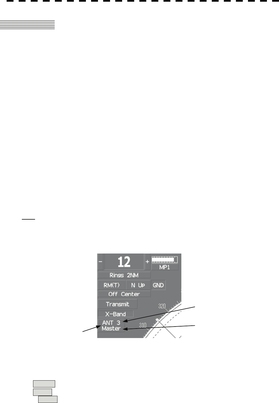
A-1
I OVERVIEW
I-i Overview
Interswitch NQE-3141 is equipment that enables free changeover between radar display units installed on
the bridge and antenna units having different characteristics.
If display unit is turned off or malfunctioned, the scanner unit can be controlled by other display unit.
If interswitch unit had malfunctioned, the radar system is switched to standalone mode.
Up to 8 units can be changed over.
When the connected scanner is changed, following setting values are automatically loaded.
Tune Adjustment (See the section 7.1.3)
Bearing Adjustment (See the section 7.1.4)
Range Adjustment (See the section 7.1.5)
Antenna Height (See the section 7.1.8)
Antenna installation location (See the section 7.1.9)
Sector Blank (See the section 7.2.2)
TNI Blank (See the section 7.2.3)
Performance monitor adjustment (See the section 7.2.4)
PRF Fine Tuning (See the section 3.8.3)
I-ii Interswitch Setup
Connection modes can be changed simply by changing the interswitch connection (upper left of the display
⑥ on page 2-16).
Note: A master display unit is always necessary for establishing a slave connection.
Before a slave display unit can be placed in transmission state, the master display unit must be
placed in transmission state.
upper left of the display
⑥ Inter switch connection
change
Connected scanner unit name
Connection mode
The upper stand indicates the connected scanner unit.
If scanner unit name is not entered. :The scanner number is indicated.
If scanner unit name is entered. :The scanner name is indicated (Max 6 characters).
For How to names of scanner unit, see the "II-vi Names of display units and scanner units".
The lower stand indicates the connection mode.
Master :Mode in which the scanner unit can be controlled by the display unit.
Slave :Mode in which the scanner unit cannot be controlled.
When Slave is selected, transmission / standby and pulse length cannot be changed. The available
range is also limited.
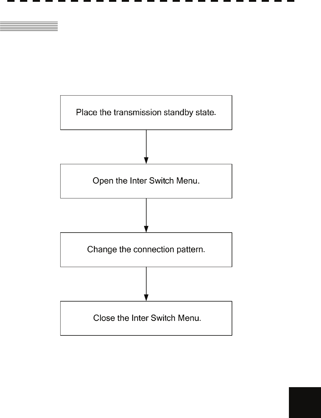
A-2
II INTERSWITCH Operation
APPENDIX
II INTERSWITCH OPERATION
Follow the flowchart below to change the current interswitch connection pattern.
II-i Operation Flow

A-3
II-ii Inter Switch Menu
The Inter Switch Menu can be opened only when the transmission standby state.
Procedures 1 Press the [STBY] key.
The transmission standby state will be placed.
2 Move the cursor onto the Interswitch connection change
(upper left of the display ⑥ on page 2-16), and press the
[ENT] key.
The Inter Switch Menu will appear.
Exit 1 Press the [0] key.
The Inter Switch Menu will close.
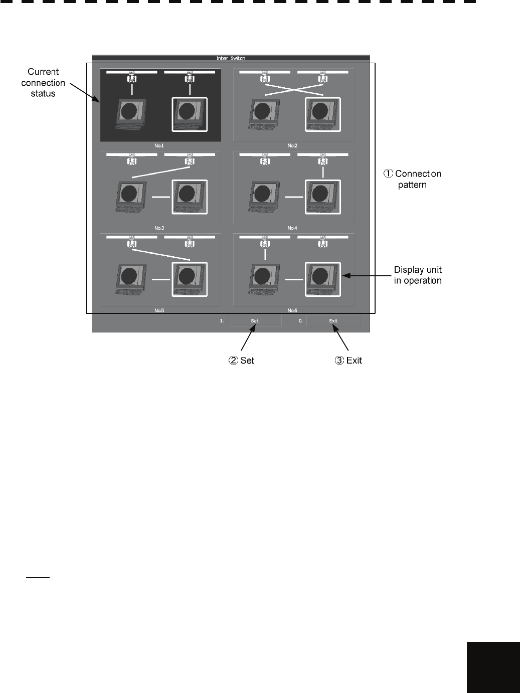
A-4
II INTERSWITCH Operation
APPENDIX
Inter Switch Menu (with 2 Display Units)
①:Connection pattern
If this button is clicked, the connection pattern is selected.
The display unit in operation is enclosed in a square □.
The background of the current connection pattern display is highlighted.
②:Set
If this button is clicked, the change of connection is determined.
③:Exit
If this button is clicked, the Inter Switch Menu is closed .
Note: If only 2 display units are installed but the interswitch is set for 3 or more display units, the Inter
Switch Menu for 3 or more display units will appear.
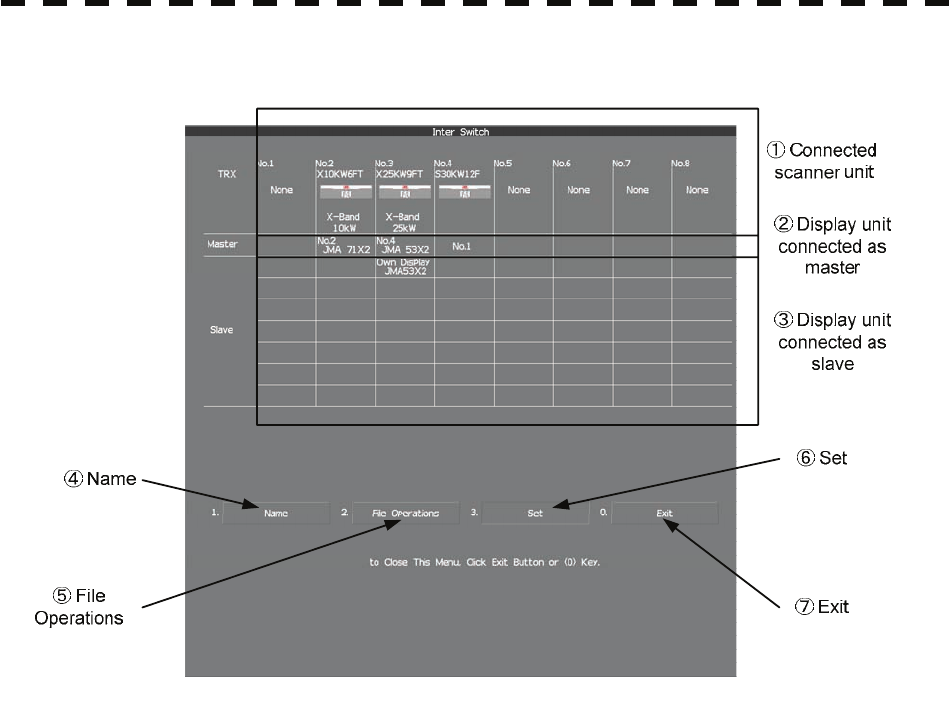
A-5
Inter Switch Menu (with 3 or More Display Units)
①:Connected scanner unit
In mode for naming a display unit or antenna unit, clicking on a unit opens the name input window.
②, ③:Display unit connected as master, and Display unit connected as
slave
If this button is clicked, select / cancel the display unit.
If this button is clicked in the naming a display unit or scanner unit mode , the name input window is
opened.
④:Name
If this button is clicked, set to the display or scanner unit rename mode.
⑤:File Operations
If this button is clicked, the File Operations menu is opened.
⑥:Set
If this button is clicked, the change of connection is determined.
⑦:Exit
If this button is clicked, the Inter Switch Menu is closed.

A-6
II INTERSWITCH Operation
APPENDIX
II-iii Change of Connection Pattern (with 2 Display Units)
If two display units are installed, a connection pattern needs to be selected.
Procedures 1 Open the Inter Switch menu (with 2 Display Units).
2 Move the cursor onto the Connection pattern (Inter Switch
Menu ① on page A-4) to be changed , and press the [ENT]
key.
The connection pattern will be selected, and Set (in Inter Switch Menu ② on
page A-4) will blink.
3 Press the [3] key.
The connection pattern will be changed.
II-iv Change of Connection Pattern (with 3 or More Display Units)
If three or more display units are installed, the layout of connection patterns needs to be set.
Procedures 1 Open the Inter Switch Menu (with 3 or More Display Units).
2 Move the cursor onto the display unit (Inter Switch Menu ②/
③ on page A-5) to be changed , and press the [ENT] key.
The selected display unit will be highlighted.
To deselect the display unit, press the [ENT] key again.
3 Move the cursor to the change-destination display unit, and
press the [ENT] key.
The selected display unit in step 2 will be switched to the change-destination display
unit, and Set (Inter Switch Menu ⑥ on page A-5) will blink.
If the change destination is empty, control will move and Set will blink.
4 Press the [3] key.
The connection pattern will be changed.
Note: A master display unit is always necessary for establishing a slave connection.

A-7
II-v Operating Connection Pattern Files (File Operations)
Frequently used connection patterns can be read easily by saving interswitch connection patterns.
[I] Loading connection patterns (Load)
Procedures 1 Open the Inter Switch Menu (with 3 or More Display Units).
2 Press the [2] key.
The File Operations menu will appear.
3 Press the [1] key.
Currently saved connection patterns in memory will be listed.
4 Press the [numeric] key corresponding to the file to be
loaded.
Confirmation Window will appear.
5 Press the [1] key.
The connection pattern will be changed.
[II] Saving connection patterns (Save)
Procedures 1 Open the Inter Switch Menu (with 3 or More Display Units).
2 Press [2] key.
The File Operations window will appear.
3 Press [2] key.
The Save menu will appear.
Currently saved connection patterns in memory will be listed.
4 Press the [numeric] key corresponding to the file to be
saved.
The Input File Name window will appear.
5 Enter the file name to be saved.
Up to 8 characters can be entered.
For the input method on the character input screen, see Section 3.3.4.
The connection pattern will be saved when the name is input.

A-8
II INTERSWITCH Operation
APPENDIX
[III] Erasing a connection pattern (Erase)
Procedures 1 Open the Inter Switch Menu (with 3 or More Display Units).
2 Press the [2] key.
The File Operations window will appear.
3 Press the [3] key.
The Erase menu will appear.
The list of connection patterns stored in the memory will be displayed.
4 Press the [numeric] key corresponding to the file to be
erased.
Confirmation Window will appear.
5 Press the [1] key.
The selected connection pattern is erased and the file name is deleted from the list.
II-vi Names of Display Units and Scanner Units
The display units and antenna units can be named.
Procedures 1 Open the Inter Switch Menu (with 3 or More Display Units).
2 Press the [1] key.
"Name" will be highlighted, indicating that the rename mode is activated.
3 Move the cursor to the display unit or scanner unit to be
renamed (Inter Switch Menu ① / ② / ③ on page A-5), and
press the [ENT] key.
The Input IND Name or the Input TXRX Name window will appear.
4 Input a new unit name.
Up to 8 characters can be input as a unit name.
For the input method on the character input menu, see Section 3.3.4.
The selected display unit or antenna unit will be renamed when the new name is input.
The scanner name is indicated in the interswitch connection change (upper left of the
display ⑥ on page 2-16) (Max 6 characters).

A-9
III REFERENCE
Preheat Time after Change of Connection Pattern
After the current interswitch connection pattern has been changed, operation needs to wait until the
system is ready. This is because the preheat time varies depending on the previous connection of
the scanner unit and display unit.
The wait time is necessary for protecting the electronic tubes that emit radio waves.
a) When not changed to a new connection pattern : Preheating not required
b) When changed to a new connection pattern and
an scanner unit had been used before the change : Preheating not required
c) When changed to a new connection pattern and
an scanner unit had not been used before the change : Preheating required
Notes on Changing Connection Pattern
An attempt to change to another connection pattern immediately after the completion of connection
pattern change may fail.
This is because internal processing still needs some preparation time upon completion of
connection pattern change. Let several seconds pass between connection pattern change
operations.
Notes on Connecting Slave Display Unit
Before a slave display unit can be placed in transmission state, the master display unit must be
placed in transmission state. If the master display unit is moved from the transmission state to the
transmission standby state, the slave display unit is forcibly placed in transmission standby state.
When they are in transmission standby state,
Master Standby is shown in the alarm indication (Brilliance / alarm on page 2-9), and the alarm
sounds.
A slave display unit cannot control tune. Tune is controlled by the master display unit. Slave
is shown in the transmitter pulse length (upper left of the display on page 2-2).
Range change for a slave display unit is limited by the range and pulse length / repetition
frequency of the master display unit. As a rule, a greater range than the range of the master
display unit cannot be set for a slave display unit. However, if the transmitter pulse length of a
slave display unit is identical to the master display unit's and the repetition frequency is within the
master display unit's, a greater range than the master display unit's can be selected for the slave
display unit. When the master display unit narrows the range or changes the transmitter pulse
length, the range of the slave display unit may be forcibly changed. In this case, Master Range
CHG is shown in the alarm indication (Brilliance / alarm on page 2-9), and the alarm sounds.
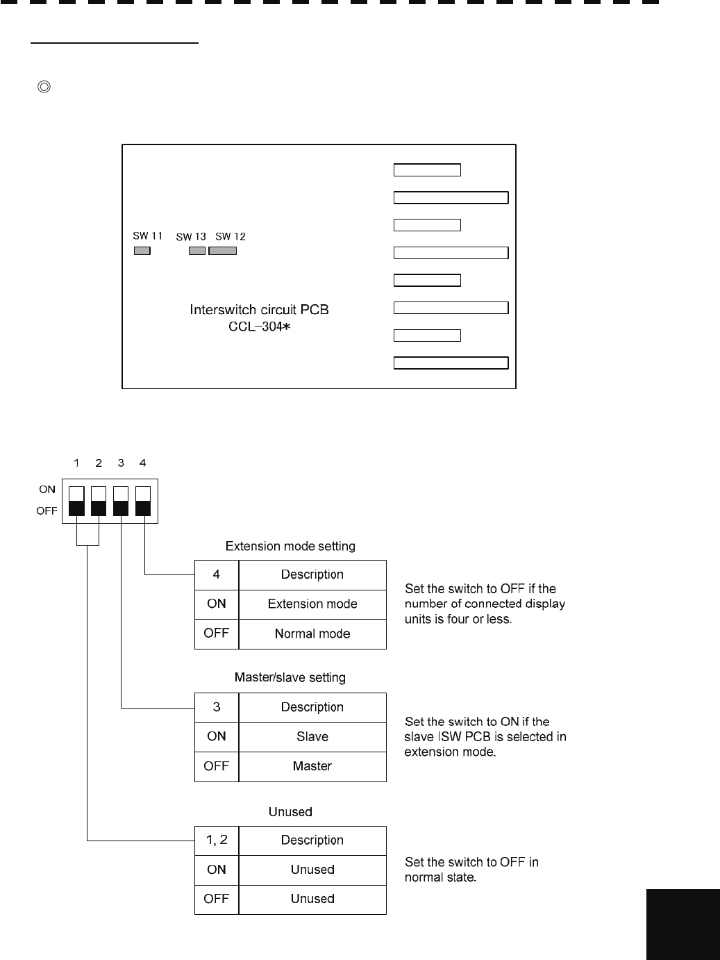
A-10
III Reference
APPENDIX
Setting at Installation
Setting of the interswitch circuit (CCL-304*)
The settings of the DIP switches SW11 to SW13 are shown below.
1) SW11 setting (extension mode and master/slave settings)
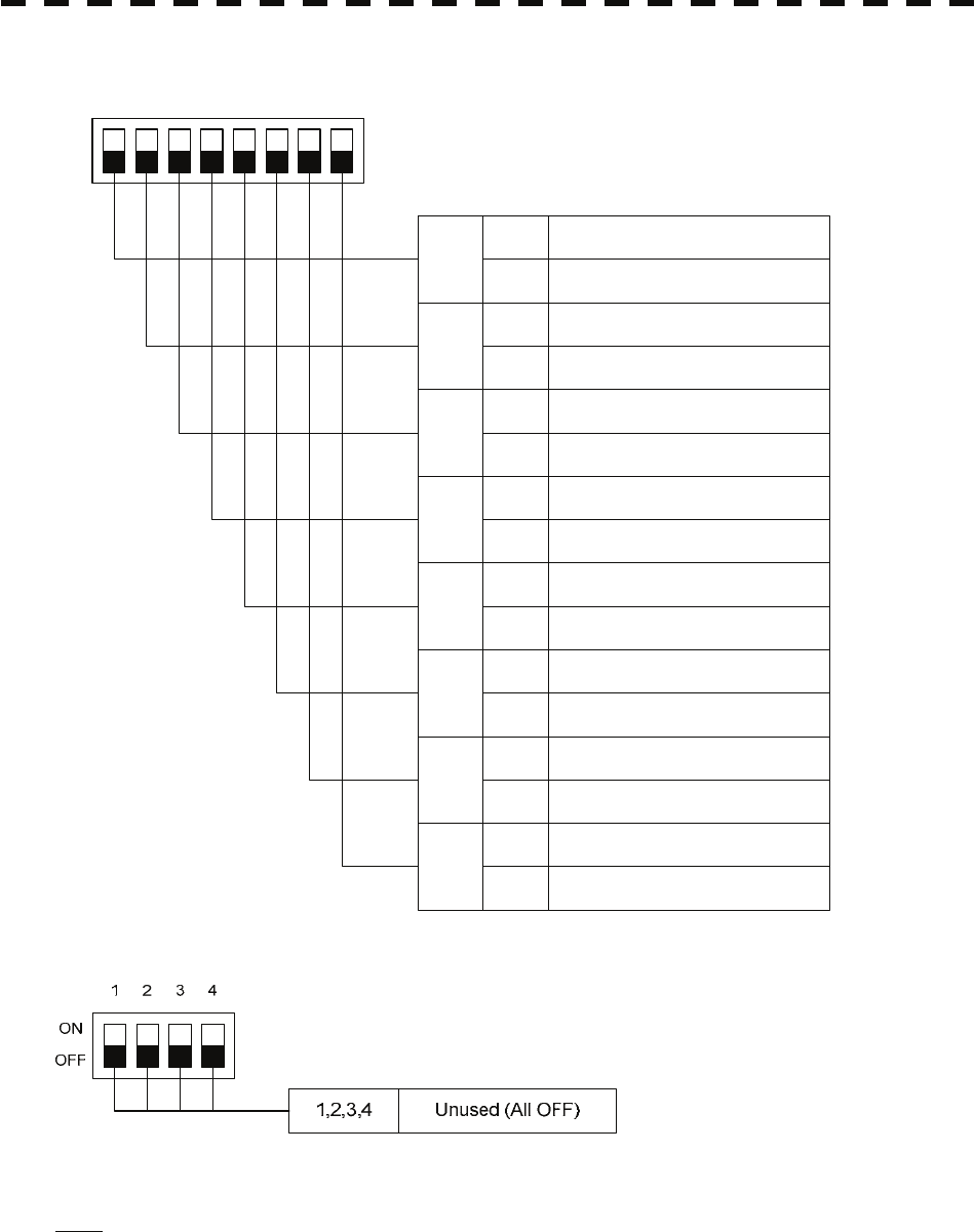
A-11
2) SW12 setting (radar connection settings)
1234
ON
OFF
8
Radar connection settings
ON No.4 scanner unit connected
OFF No.4 scanner unit not connected
5678
7ON No.4 display unit connected
OFF No.4 display unit not connected
6ON No.3 scanner unit connected
OFF No.3 scanner unit not connected
5ON No.3 display unit connected
OFF No.3 display unit not connected
4ON No.2 scannerunit connected
OFF No.2 scannerunit not connected
3ON No.2 display unit connected
OFF No.2 display unit not connected
2ON No.1 scannerunit connected
OFF No.1 scanner unit not connected
1ON No.1 display unit connected
OFF No.1 display unit not connected
3) SW13 (unused)
Note: Before the DIP switches of the interswitch circuit can be set, the interswitch breaker must be turned
off in order to ensure safety operation.
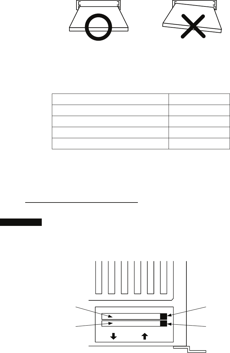
HOW TO INSERT AND REMOVE A CARD
Insert or remove the JRC coastline ROM card, ERC card, C-MAP card and memory card according to
the procedures below.
Note: Keep a card horizontal when inserting it into a card slot. An inclined card causes a failure.
Do not simultaneously insert a JRC coastline ROM card, an ERC card and C-MAP card into
the card slot. A malfunction will occur on the display.
Insert the card into the specified slot according to the following table:
Card type Insertion slot No.
JRC card Either one
ERC card Either one
C-Map NT+ detail card Either one
Memory card Either one
Note: The Background of C-Map has been built in, don’t insert C-Map NT+ background card.
If the background card is inserted, the system will malfunction.
Insert a card into processor unit
Procedures 1 Remove the rubber packing located at the backside of the processing
unit cabinet, and expose the card slot.
Backside of the processor unit
Upper stage : card slot 2
Lower stage : card slot 1
12
Card slot 2 eject button
Card slot 1 eject button
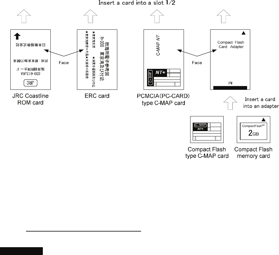
2 Insert the card in the direction indicated by the arrow.
3 Insert the card until the card slot's eject button protrudes and
complete the installation of a card.
Eject a card from processor unit
Procedures 1 Push the eject button corresponding to the desired card slot.
2 remove a card from processor unit
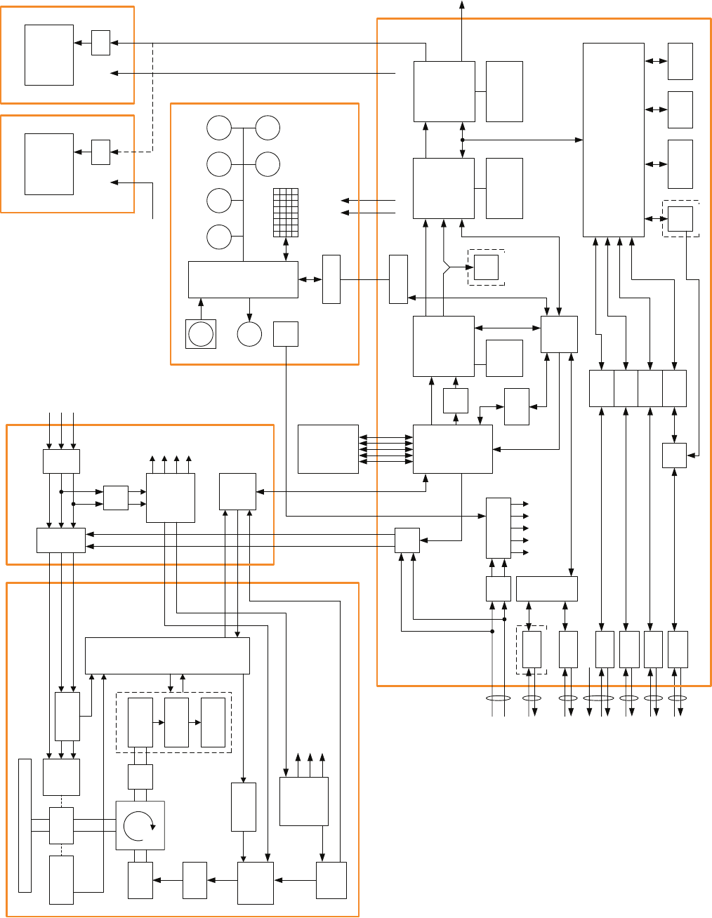
32bit bus
MULTI RAIN SEA
NMEA I/F
NMEA I/F
NMEA I/F
NMEA I/F
NMEA I/F
Relay
Filter Power Supply
GAIN
EBL VRM
CPU
PWR
SW
Signal Proc ASIC
STC/FTC/CFAR
IR/AVE/GZ alarm
Radar Draw ASIC
Scan convert
Scan correlation
Trail process
Graphics ASIC
Map draw
Graphics draw
Main CPU
Communication
User I/F
Main control
TrackBall
Buzzer
Key Matrix
Encoder
RS422 I/F
ISW
SEL ADC
RS485
I/F
RS422 I/F
Sub
CPU
ARPA
DSP
Sweep
memory
Frame memory
Radar Echo
Radar Trails
Frame memory
Map
Graphics
DDR SDRAM
work FROM
program SRAM
Back-up
CPU
AIS
SIO
SIO
SIO
SIOSEL
SEL PWRCNT
MTR+/-
+12V
OPTION
Operation Unit NCE-5172
Operation Unit NCE-5171 (Option)
LCD Monitor NWZ-173
19inch LCD
I/F
P12V
+12V
+12V
RGB
Radar Process Unit NDC-1417
GYRO
LOG
GPS
COMPASS
GPS
PC
NAV2
NAV1
Analog RGB External
Display
PWRCNT
SLOT ANTENNA
ROTARY
JOINT
ENCODER MOTOR
MAG
PULSE
TRANS
Modulator
MIC
IF AMP
VIDEO AMP
AC220V +10%, -10%
50/60Hz,3φ
Scanner Unit NKE-1064
Scanner Unit NKE-3710-8
TRL
Pulse Width
control
Power Supply +5V
±12V
+24V
Heater
Control
OPTION
OPTION
T/R
Control
Relay
Safety Switch
Power Supply
Relay
Line
Filter
MH/MN
DC65V
Power Unit NBL-315
+24V
-15V
+15V
+12V
P12V
-12V
+5V
+3.3V
+12V
Interface
C2
U
V
W
+9V/9E
X1/X2
DC24V
-10%
+50%
Monitor Unit NWZ-170
(Option)
23.1inch
LCD
I/F
RGB
AC100/100/115V
AC220/230/240V
50/60Hz,1φ
Receiver
GYRO I/F
ISW unit
(OPTION)
PWRCNT
BP/BZ
VD
TI
MTR+/-
Fig.1 Block Diagram of RADAR Type JMA-5352-9R, JMA-5362-8R
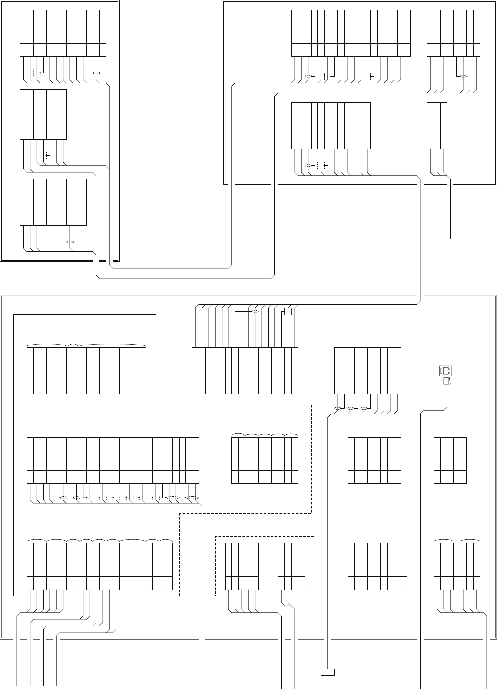
1TRX+(1A)
2TRX-(2A)
3VD
4VDE
5TRG
6TRGE
7BP
8BPE(GND)
9BZ
10 BZE
TB611
11 COM+(MTR+)
12 COM-(MTR-)
YEL.T
BLK.T
BLK
ORN
YEL
GRN
WHT
1U
2V
3W
TB601
AC MAIN IN
1+15V
2-15V
3
REV
4
5MO
6TI
7TIE
8PW
9TNI
10 TNC
TB612
11 C2
12 BP
13 BPE
14 BZ
15
VD
16 E
17 E
18 E
19-CORES CABLE
CFQ-6912
(JRC SUPPLY)
BLU.T
RED
GRN
WHT
YEL
1U2
2V2
3W2
4MU2
5MV2
6MW2
7
8MH
9
10 MN
TB101
165
265E
3C2
4BP
5BPE
6BZ
7REV
TB201
1MO
2PW
3TI
4TIE
TB202
NBL-315 POWER UNIT
NKE-1064/3710-8 SCANNER UNIT
SHIP’S MAIN
AC220V
+10%, -10%
50/60Hz 3φ
0.6/1kV-DPYC-6
14-CORES CABLE
H-2695110056
(JRC SUPPLY)
VDE
WHT.T
RED
BRN
SKY
BLU
SKY
BLK.T
BLK
PUR
1U2
2V2
3
4
5MN
6MH
765
865E
TB602
W2
GRN.TT
YEL.TT
BRN.TT
RED.T
BLU.T
5TNI
6TNC
7
E
8
+15V
9
-15V
10 E
11 E
12 VD
13 VDE
GRN
WHT
YEL
BRN
SKY
BLU
SKY
BLK
PUR
RED
RED
BLU.T
WHT.T
BLK.T
GRN.TT
YEL.TT
BRN.TT
BLU.T
RED.T
28-CORES CABLE
H-2695111160
(JRC SUPPLY)
1
1
NOTE:TB611
下記各ケーブルはTB611側では未使用の為、それぞれ端末
絶縁処理を施すこと
Insulate of the following each wire’s terminal, because it
is not connected to TB611.
BLU.T/GRY.T, PUR.T/BRN.T, WHT.T/ORN.T,
RED.T/GRN.T, SKY.T, PNK.T
1NAV1TXDE
2NAV1TXD-
3NAV1TXD+
4NAV1RXDE
5NAV1RXD-
6NAV1RXD+
7GPSTXD-
8GPSTXD+
9GPSRXD-
10 GPSRXD+
TB4303
11 NAV2RXD-
12 NAV2RXD+
13 ARPATXD-
14 ARPATXD+
15 ARPAALM-
16 ARPAALM+
17 SYSALM-
18 SYSALM+
19 EVENT-
20 EVENT+
21 COMPAS-
22 COMPAS+
NMEA0183
OUTPUT
NMEA0183
INPUT
GPS
OUTPUT
GPS
INPUT
NMEA0183
INPUT
NMEA0183
OUTPUT
CONTACT
OUT
CONTACT
IN
NMEA0183
INPUT
1PWRIN-
2PWRIN+
3PWROUT-
4PWROUT+
5VDINE
6VDIN
7VDOUTE
8VDOUT
9TRGINE
10 TRGIN
TB4301
11 TRGOUTE
12 TRGOUT
13 BPINE
14 BPIN
15 BPOUTE
16 BPOUT
17 BZINE
18 BZIN
19 BZOUTE
20 BZOUT
21 MTRINE
22 MTRIN-
23 MTRIN+
24 MTROUTE
25 MTROUT-
26 MTROUT+
INTER SWITCH
BRN
PNK
BLK
ORG
RED
BLU
PUR
YEL
WHT
GRN
WHT
YEL
WHT
BLU
2
1
CQD-1937A TERMINAL BOARD
NCD-4530 DISPLAY UNIT
11/R1
22/S1
33/S2
4S3
55/R2
TB10
NCT-59A GYRO I/F UNIT (OPTION)
GYRO SYNC/STEP
1LOGP+
2LOGP-
3LOGS+
4LOGS-
TB20
LOG SYNC/PULSE
1NC
2PCRXD
3PCTXD
4NC
5GND
6NC
7PCRTS
8PCCTS
J8
9NC
RS232C PORT
1 1A
2 1A
3 1A
4NC
5 2A
6 2A
7 2A
J1
BLK
RED
RED
RED
BLK
BLK
POWER INPUT
1RBVDE
2RBVD
3TRGOE
4TRGO
5BPOE
6BPO
7BZOE
8BZO
TB4302
9VDOE
SLAVE OUTPUT
10 VDO
RADR
BUOY IN
TRG
OUT
B PULSE
OUT
Z PLUSE
OUT
VIDEO
OUTPUT
1GPSCTXD-
2GPSCTXD+
3GPSCRXD+
4GPSCRXD-
5GND
6ALM+
7ALM-
8 +5V
J5
To JLR-10/20/30
1 +12V
2GND
3GPSRXD-
4GPSRXD+
5GPSTXD+
J3
To GPS
1MOTOR-
2MOTOR-
3TRX-
4MOTOR+
5MOTOR+
6TRX+
7GND
8+12V
9COM-
10 COM+
TB4310
11 BZE
12 BZ
13 BPE
14 BP
15 TRGE
16 TRG
17 VDE
18 VD
1M-
2M-
3M+
4M+
52A
6GND
7VDE
8+12V
91A
10 VD
J2
11 MTR+
12 BZ
13 MTR-
14 TRGE
15 TRG
16 BP
1RED
2RED_E
3GRN
4GRN_E
5BLU
6BLU_E
7HS
8HS_E
9VS
10 VS_E
J4406 in CDC-1332
SLAVE RGB OUTPUT
+
-
BLU.T/GRY.T
POWER
OUTPUT
+12V
OUTPUT
SLAVE
INPUT
PUR.T/BRN.T
WHT.T/ORN.T
RED.T/GRN.T
BLK.T/SKY.T
BLK
YEL.T/PNK.T
ORN
YEL
GRN
WHT
3-
2-
2+
3+
1-
1+
1-
1+
1+
1-
250V-TTYCS-4
250V-TTYCS-1
250V-TTYCS-1
18-CORES
COMPOSITE
CABLE
H-2695111153
(JRC SUPPLY,
OPTION)
250V-MPYCYS-7
250V-DPYCYS-1.5
CFQ-5436-5
(5m JRC SUPPLY)
Dsub 15pin
INTER SWITCH
CFQ-8914
VDR or
Remote monitor
RECTIFIER
UNIT
GYRO
LOG(200P)
AIS
DGPS
LOG(NMEA)
1+
1-
JRC VDR
(for remote maintenance)
250V-TTYCS-1
NOTE: TB4310 7-8
12V出力を外部機器の電源として使用することはできません
12V output is not available for external device’s power supply.
(JRC SUPPLY, OPTION)
DC24V
J10
RJ-45 LAN
LAN PLUG CONNECTOR
(JRC SUPPLY)
LAN CABLE
H-7ZCNA0483
(JRC SUPPLY,
OPTION)
JRC LAN
Fig.2 Terminal Board Connection Diagram of RADAR, Type JMA-5352-9R, JMA-5362-8R
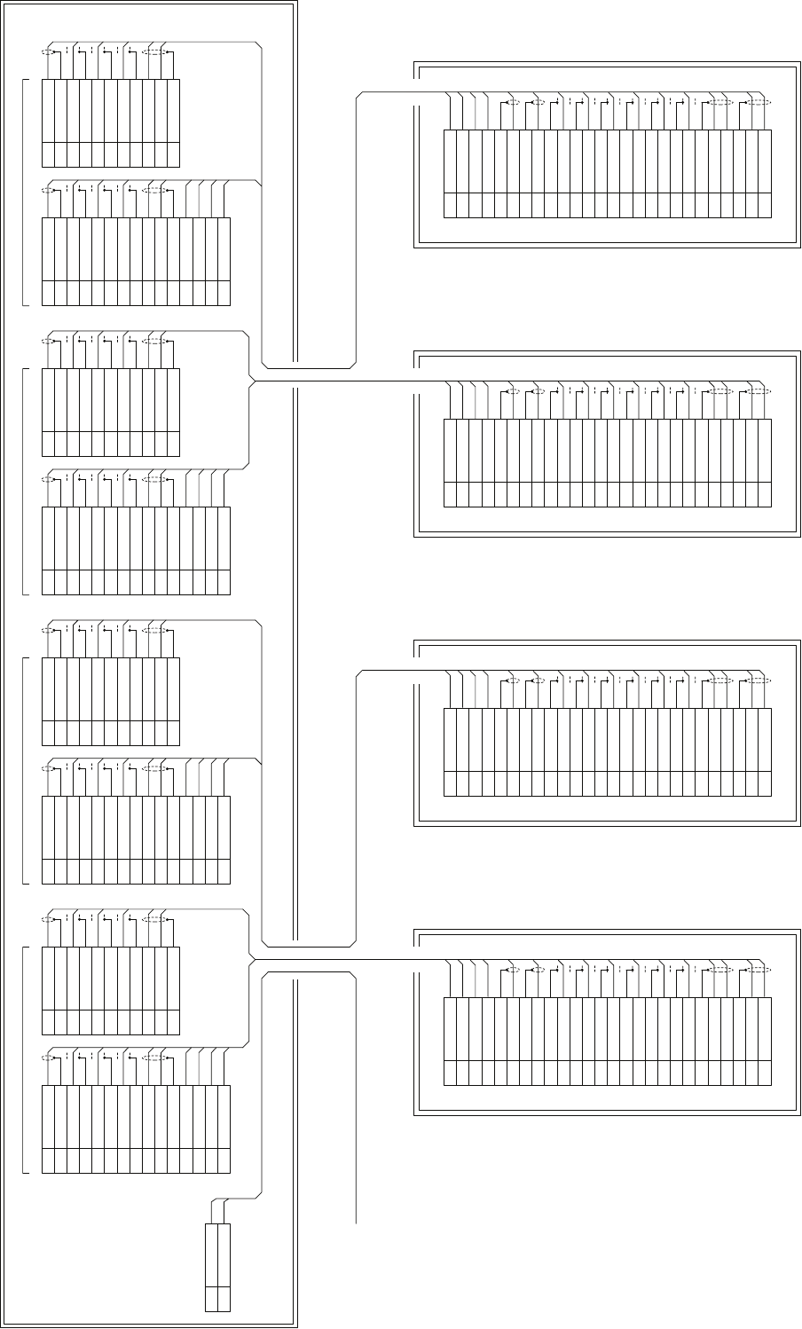
1PWRIN-
2PWRIN+
3PWROUT-
4PWROUT+
5VDINE
6VDIN
7VDOUTE
8VDOUT
9TRGINE
10 TRGIN
TB4301
11 TRGOUTE
12 TRGOUT
13 BPINE
14 BPIN
15 BPOUTE
16 BPOUT
17 BZINE
18 BZIN
19 BZOUTE
20 BZOUT
21 MTRINE
22 MTRIN-
23 MTRIN+
24 MTROUTE
25 MTROUT-
26 MTROUT+
in NDC-1417
BRN
PNK
BLK
ORG
RED
BLU
PUR
YEL
WHT
GRN
WHT
YEL
WHT
BLU
2
1
13 PWRINE
12 PWRIN
15 PWROUTE
14 PWROUT
2VDINE
1VDIN
2VDOUTE
1VDOUT
4TRGINE
3TRGIN
TB911
4TRGOUTE
3TRGOUT
6BPINE
5BPIN
6BPOUTE
5BPOUT
8BZINE
7BZIN
8BZOUTE
7BZOUT
11 MTRINE
10 MTRIN-
9MTRIN+
11 MTROUTE
10 MTROUT-
9MTROUT+
BRN
PNK
BLK
ORG
WHT
YEL
TB912
WHT
BLU
GRN
YEL
BLU
1 2
WHT
PUR
RED
CH-1
JMA-5300MK2 Series RADAR
1PWRIN-
2PWRIN+
3PWROUT-
4PWROUT+
5VDINE
6VDIN
7VDOUTE
8VDOUT
9TRGINE
10 TRGIN
TB4301
11 TRGOUTE
12 TRGOUT
13 BPINE
14 BPIN
15 BPOUTE
16 BPOUT
17 BZINE
18 BZIN
19 BZOUTE
20 BZOUT
21 MTRINE
22 MTRIN-
23 MTRIN+
24 MTROUTE
25 MTROUT-
26 MTROUT+
in NDC-1417
BRN
PNK
BLK
ORG
RED
BLU
PUR
YEL
WHT
GRN
WHT
YEL
WHT
BLU
2
1
13 PWRINE
12 PWRIN
15 PWROUTE
14 PWROUT
2VDINE
1VDIN
2VDOUTE
1VDOUT
4TRGINE
3TRGIN
TB913
4TRGOUTE
3TRGOUT
6BPINE
5BPIN
6BPOUTE
5BPOUT
8BZINE
7BZIN
8BZOUTE
7BZOUT
11 MTRINE
10 MTRIN-
9MTRIN+
11 MTROUTE
10 MTROUT-
9MTROUT+
BRN
PNK
BLK
ORG
WHT
YEL
TB914
WHT
BLU
GRN
YEL
BLU
1 2
WHT
PUR
RED
CH-2
JMA-5300MK2 Series RADAR
1PWRIN-
2PWRIN+
3PWROUT-
4PWROUT+
5VDINE
6VDIN
7VDOUTE
8VDOUT
9TRGINE
10 TRGIN
TB4301
11 TRGOUTE
12 TRGOUT
13 BPINE
14 BPIN
15 BPOUTE
16 BPOUT
17 BZINE
18 BZIN
19 BZOUTE
20 BZOUT
21 MTRINE
22 MTRIN-
23 MTRIN+
24 MTROUTE
25 MTROUT-
26 MTROUT+
in NDC-1417
BRN
PNK
BLK
ORG
RED
BLU
PUR
YEL
WHT
GRN
WHT
YEL
WHT
BLU
2
1
13 PWRINE
12 PWRIN
15 PWROUTE
14 PWROUT
2VDINE
1VDIN
2VDOUTE
1VDOUT
4TRGINE
3TRGIN
TB915
4TRGOUTE
3TRGOUT
6BPINE
5BPIN
6BPOUTE
5BPOUT
8BZINE
7BZIN
8BZOUTE
7BZOUT
11 MTRINE
10 MTRIN-
9MTRIN+
11 MTROUTE
10 MTROUT-
9MTROUT+
BRN
PNK
BLK
ORG
WHT
YEL
TB916
WHT
BLU
GRN
YEL
BLU
1 2
WHT
PUR
RED
CH-3
JMA-5300MK2 Series RADAR
1PWRIN-
2PWRIN+
3PWROUT-
4PWROUT+
5VDINE
6VDIN
7VDOUTE
8VDOUT
9TRGINE
10 TRGIN
TB4301
11 TRGOUTE
12 TRGOUT
13 BPINE
14 BPIN
15 BPOUTE
16 BPOUT
17 BZINE
18 BZIN
19 BZOUTE
20 BZOUT
21 MTRINE
22 MTRIN-
23 MTRIN+
24 MTROUTE
25 MTROUT-
26 MTROUT+
in NDC-1417
BRN
PNK
BLK
ORG
RED
BLU
PUR
YEL
WHT
GRN
WHT
YEL
WHT
BLU
2
1
13 PWRINE
12 PWRIN
15 PWROUTE
14 PWROUT
2VDINE
1VDIN
2VDOUTE
1VDOUT
4TRGINE
3TRGIN
TB917
4TRGOUTE
3TRGOUT
6BPINE
5BPIN
6BPOUTE
5BPOUT
8BZINE
7BZIN
8BZOUTE
7BZOUT
11 MTRINE
10 MTRIN-
9MTRIN+
11 MTROUTE
10 MTROUT-
9MTROUT+
BRN
PNK
BLK
ORG
WHT
YEL
TB918
WHT
BLU
GRN
YEL
BLU
1 2
WHT
PUR
RED
CH-4
JMA-5300MK2 Series RADAR
2695111153 (JRC SUPPLY)
18-CORES COMPOSITE CABLE
0.6/1kV-DPYC-1.5
SHIP’S MAIN
AC100-240V
50/60Hz 1Φ
30VAmax
NQE-3141-4A INTER-SWITCH UNIT
2V
1 U
TB901
2695111153 (JRC SUPPLY)
18-CORES COMPOSITE CABLE
2695111153 (JRC SUPPLY)
18-CORES COMPOSITE CABLE
2695111153 (JRC SUPPLY)
18-CORES COMPOSITE CABLE
Fig.3 Terminal Board Connection
Diagram of RADAR and
INTERSWITCH Unit, Type
NQE-3141
(
O
p
tion
)
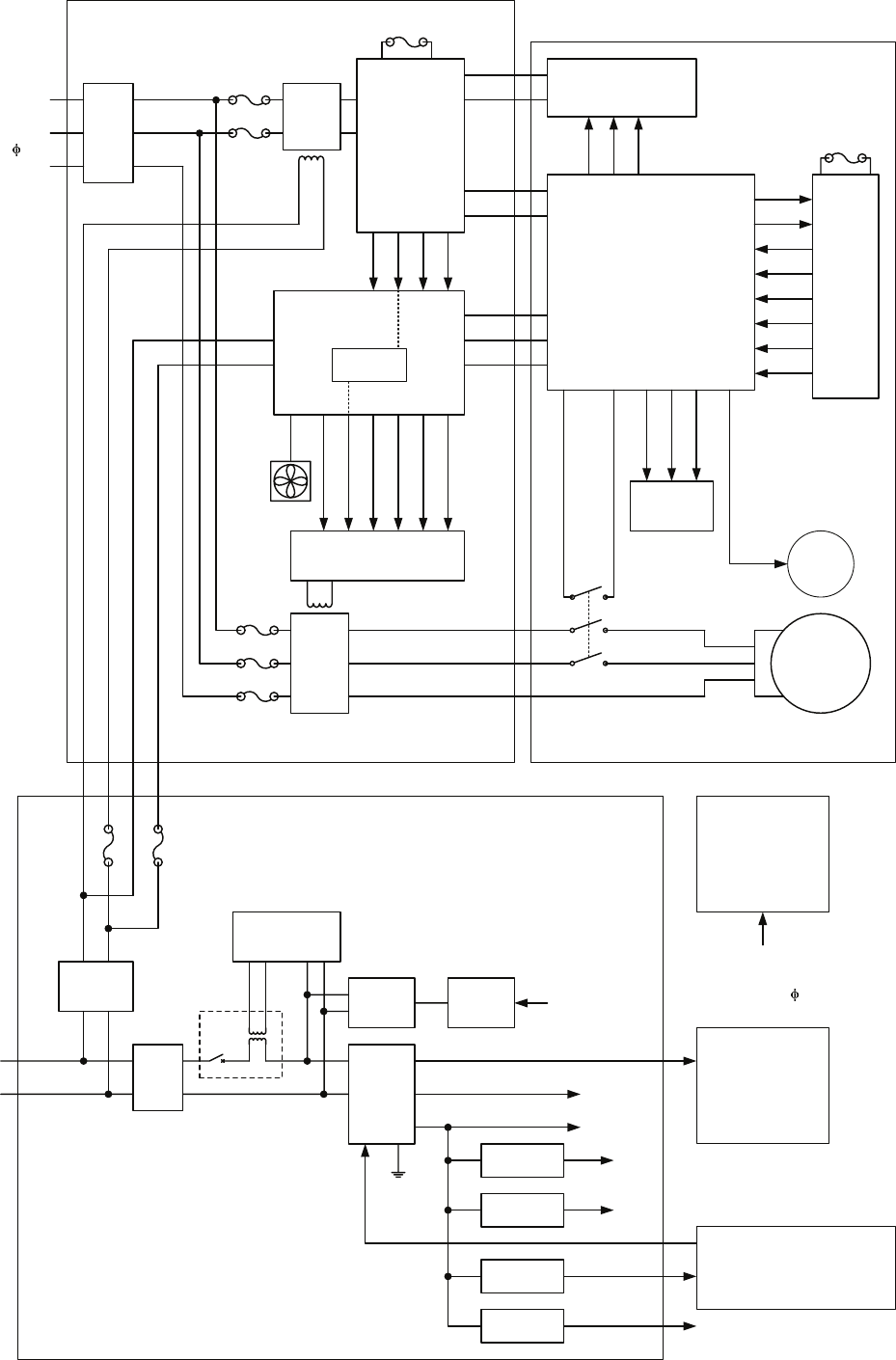
DC24V
+50%
-10%
AVR
F3
F2
Filter
PWR
SENSE
P12V
±12V
AVR
PWR
CONT
Relay
+5V AVR
+3.3V AVR
Poly-SW
Poly-SW
-12V 0.2A
+12V 1.0A
Analog
Analog
Logic
Logic
4A
7A
PWR-ON
0.5A
0.5A
RADAR PROCESS UNIT NDC-1417
LCD MONITOR
NWZ-173
POWER-SW
OPERATION UNIT NCE-5172
OPERATION UNIT NCE-5171
(OPTION)
To GPS (SW)
4A
Filter
AC220V
+10%, -10%
50/60Hz 3
Relay
F601
F602
F603
F604
F605
Relay
F1
I/F Circuit
+5V AVR
MH
MN
65
65E
+24V
+15V
+12V
-15V
MTR+
MTR-
+15V
+12V
-15V
+5V
T/R Control Circuit
POWER UNIT NBL-315
MTR+
MTR-
I/F Circuit
+15V
-15V
M
+15V
-15V
+15V
C2
AVR
65
65E
+24V
+12V
9V
9E
+5V
-12V
+24V
Modulator
+24V
X1
X2
C2
REC
FAN
F1
SCANNER UNIT NKE-1064/3710-8
+12V
MPS(+5V)
Encoder
MONITOR UNIT
NWZ-170
AC100/110/115V
AC220/230/240V
50/60Hz 1
Fig.4 Power System Diagram of RADAR, Type JMA-5352-9R, JMA-5362-8R
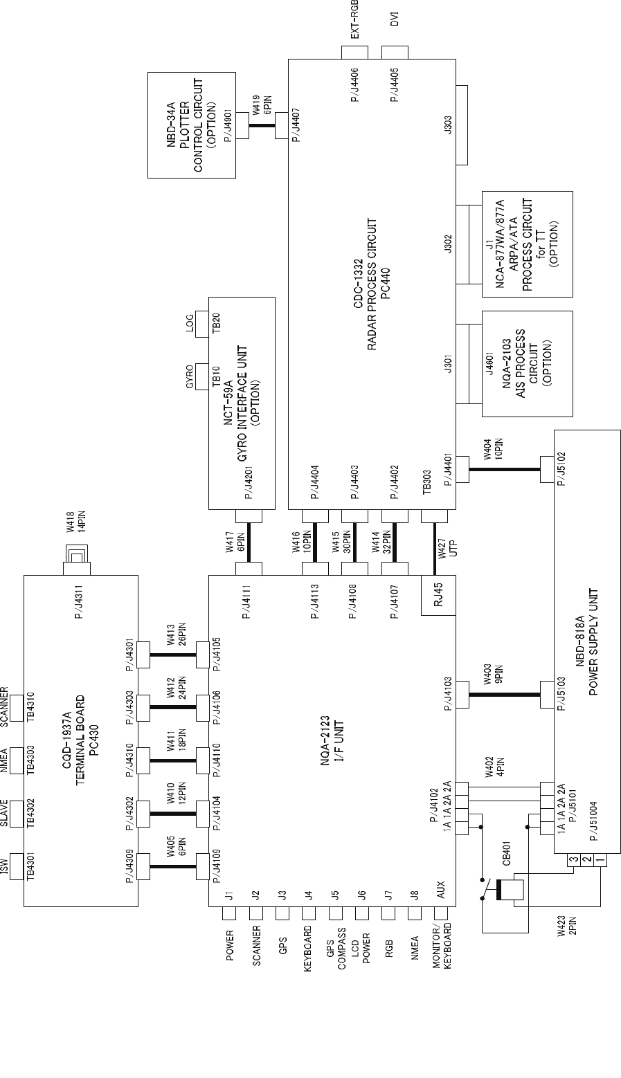
Fig.5 Internal Connection Diagram of RADAR PROCESS UNIT, Type NDC-1417
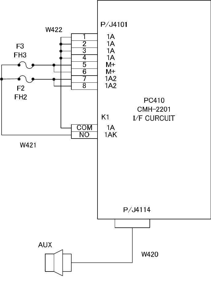
Fig.6 Internal Connection Diagram of INTERFACE UNIT, Type NQA-2123
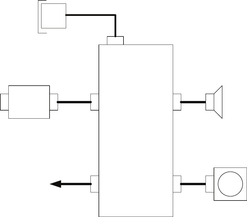
PC601
CCK-980
OPERATION CURCUIT
P/J6003
W603
P/J6002
P/J6004
P/J6001
W604
W602
W601
PC611
CQC-1205
PS/2
P/J6103P/J6101 SP601
B601
PS/2
I/F
Radar Process Unit
NDC-1417
P/J6005
S601
SA601
W605
Fig.7 Internal Connection Diagram of OPERATION UNIT, Type NCE-5172
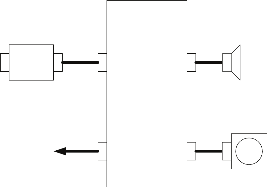
PC600
CCK-979
OPERATION CURCUIT
P/J6003
W603
P/J6002
P/J6004
P/J6001
W604
W602
W601
PC610
CQC-1204
PS/2
P/J6103P/J6101 SP601
B601
PS/2
I/F
Radar Process Unit
NDC-1417
Fig.8 Internal Connection Diagram of OPERATION UNIT, Type NCE-5171 (Option)
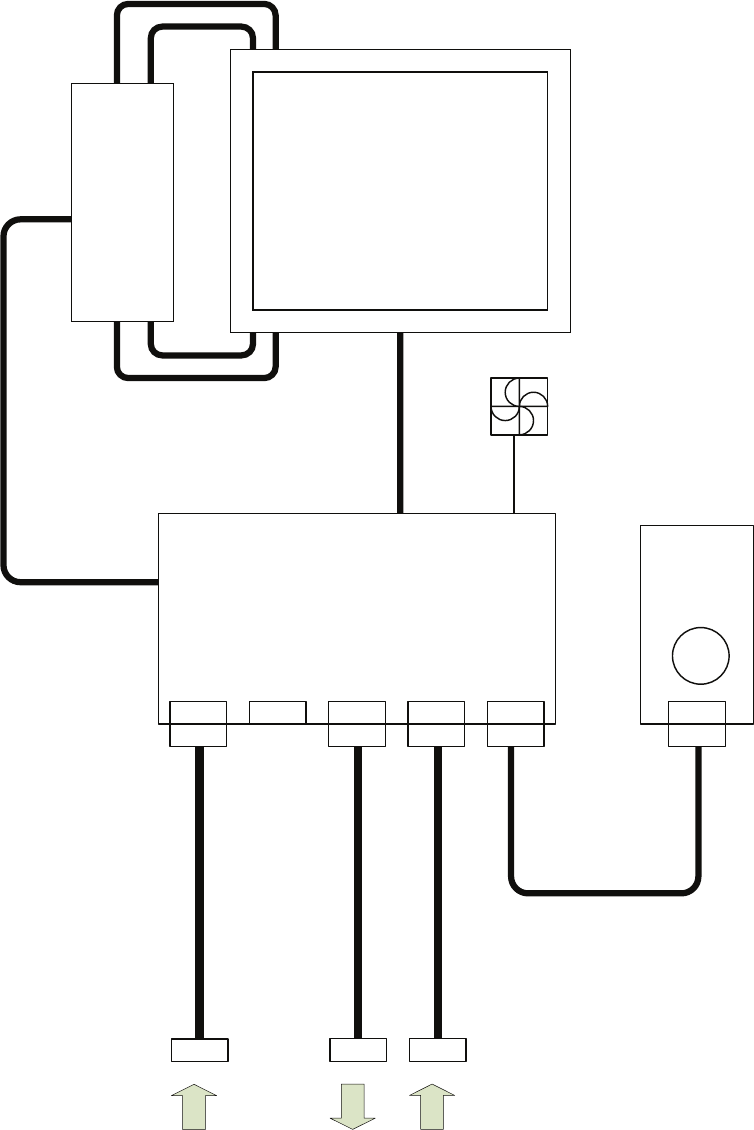
I/F Circuit
H-CMH-2227
7P
BRILL
7P
DC12V
3P
FAN
ALM
9P
DVIRGB
H-CCK-989
Brilliance
Control
Circuit
5m
RGB 5m
NDC-1417 J6
VIDEO DC OUT
3P14P
15P
H-CBP-173A
Blower
Circuit
H-CML-771
19inch LCD Panel
H-CBF-38
Inverter Circuit
15P
DC12V 5m
NDC-1417
AUX
NDC-1417 J7
VIDEO
Fig.9 Internal Connection Diagram of LCD MONITOR, Type NWZ-173
H-CML-799
23.1inch LCD
8P
BRILL
8P
AC100/2
20V
3P
FAN
ALM
9P
DVIRGB
H-CCK-972
LCD
Operation
Circuit
5m
RGB 5m
3P14P15P
15P
AC 5m
NDC-1417
AUX
NDC-1417 J7
VIDEO
AC100/110/115/220/
230/240V 50/60Hz 1
Fig.10 Internal Connection Diagram of MONITOR UNIT, Type NWZ-170 (Option)
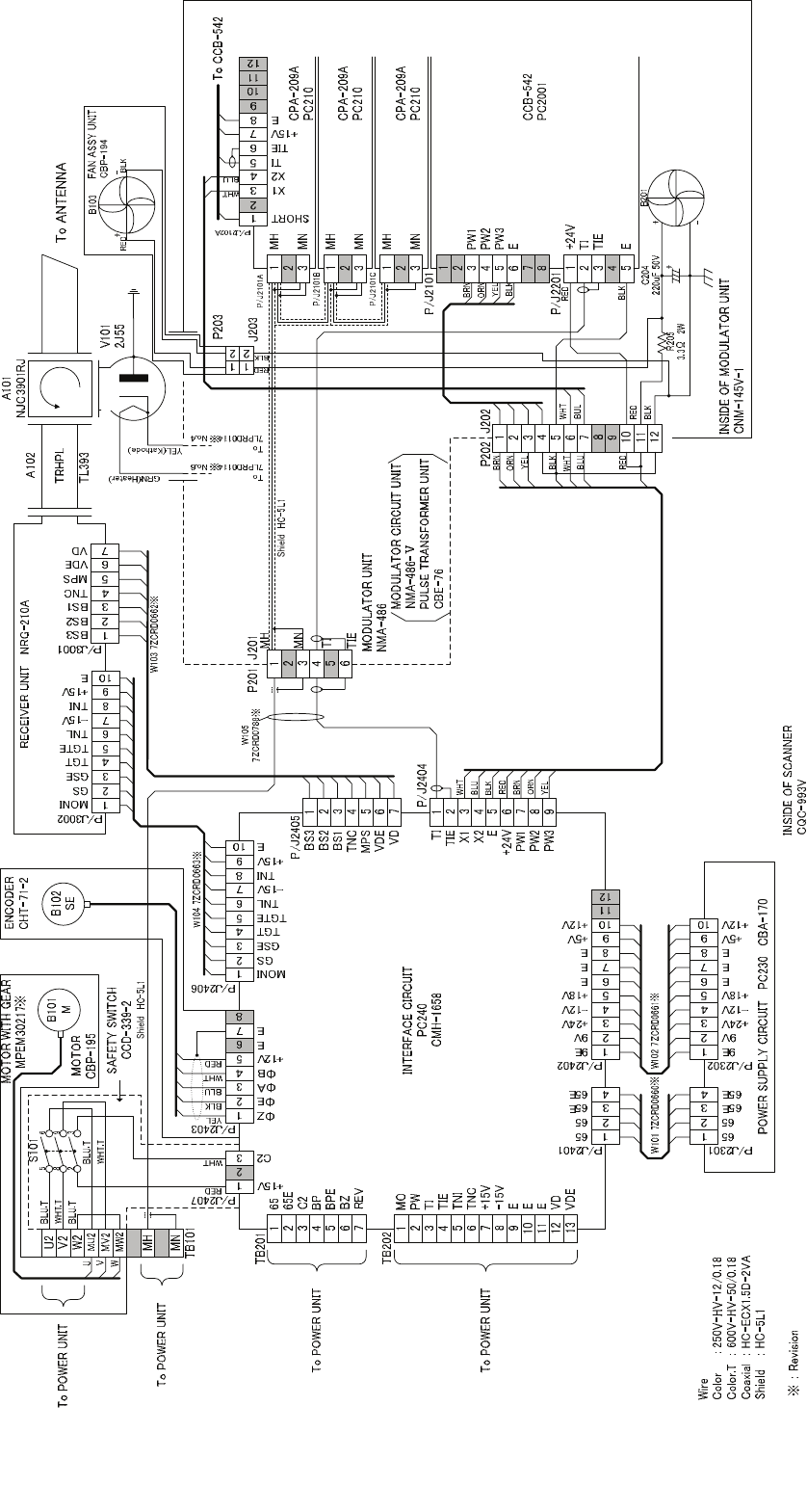
Fig.11 Internal Connection Diagram of SCANNER UNIT, Type NKE-1064
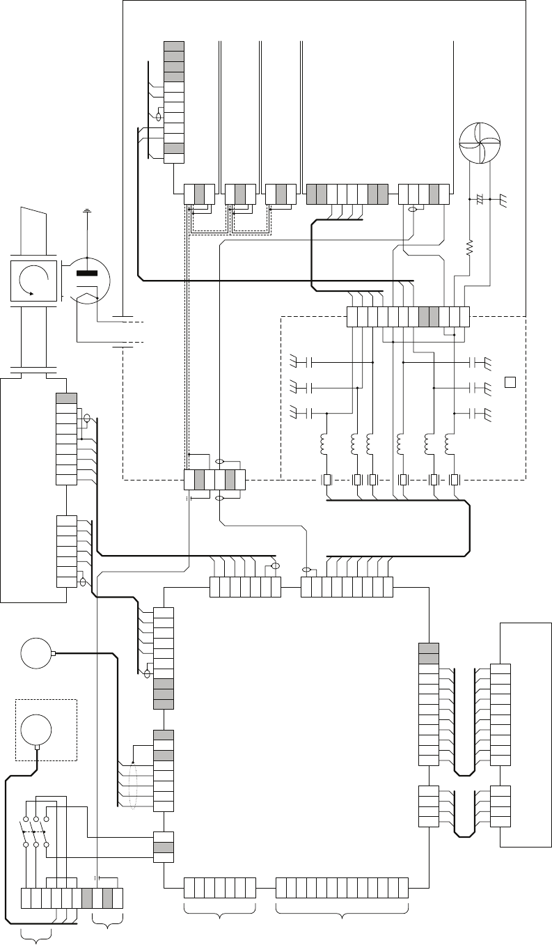
RECEIVER UNIT NRG-213/213A
Including W103 and W104 (NRG-213A)
POWER SUPPLY CIRCUIT PC230 CBA-170
1
2
3
4
P/J2301
65
65
65E
65E
1
2
3
4
5
6
7
8
9
10
P/J2302
9E
9V
+24V
-12V
+18V
E
E
E
+5V
W101 7ZCRD0660*
MN
MH
MV2
MW2
MU2
W2
V2
U2
S101
5
8
2
6
9
3
B101
M
MOTOR
CBP-106
BLU.T
WHT.T
BLU.T
RED.T
WHT.T
U
V
W
YEL
BLK
BUL
WHT
RED
W104 7ZCRD0663* (NRG-213)
7ZCRD1638* (NRG-213A)
W103 7ZCRD0662* (NRG-213)
7ZCRD1637* (NRG-213A)
INTERFACE CIRCUIT
PC240
CMH-1658
1
2
3
4
5
6
7
8
9
10
P/J2406
E
+15V
TNI
-15V
TNL
TGTE
TGT
GSE
GS
MONI
1
2
3
4
5
6
7
8
P/J2403
E
E
+12V
ΦB
ΦA
ΦE
ΦZ
1
2
3
P/J2407
C2
+15V
1
2
3
4
5
6
7
TB201
65
65E
C2
BP
BPE
BZ
REV
1
2
3
4
5
6
7
8
9
10
11
12
13
TB202
MO
PW
TI
TIE
TNI
TNC
+15V
-15V
E
E
E
VD
VDE
1
2
3
4
P/J2401
65
65
65E
65E
1
2
3
4
5
6
7
8
9
10
11
12
P/J2402
9E
9V
+24V
-12V
+18V
E
E
E
+5V
1
2
3
4
5
6
7
8
9
P/J2404
PW3
PW2
PW1
+24V
E
X2
X1
TIE
TI
1
2
3
4
5
6
7
P/J2405
VD
VDE
MPS
TNC
BS1
BS2
BS3
B102
SE
C109
1
2
3
4
5
6
7
8
9
10
11
12
C110
C111
C112
C113
C114
L101
L102
L103
L104
L105
L106
1
2
3
4
5
6
P/J201
TIE
TI
MN
MH
C103 C104 C105
C106 C107 C108
C103~C108: 0.1uF 50V
C109~C114: 10000pF 250V
L101~L106: SN-8S-500
1
2
3
4
5
6
7
8
1
2
3
4
1
2
3
1
2
3
1
2
3
P202 J202
5
1
2
3
4
5
6
7
8
9
10
11
12
TRHPL
R205
3.3Ω 2W
C204
220uF 50V
+
+
-
B201
To CCB-542
MH
MN
MH
MN
MH
MN
+24V
PW1
PW2
PW3
E
TI
TIE
E
SHORT
X1
X2
TI
TIE
+15V
E
CPA-209A
PC210
CPA-209A
PC210
CPA-209A
PC210
CCB-542
PC2001
P/J2101
P/J2101
P/J2101
P/J2102
MODULATOR UNIT
NMA-195A
To ANTENNA
To POWER UNIT
To POWER UNIT
To POWER UNIT
To POWER UNIT
WHT
BLU
BLK
RED
BRN
ORN
YEL
BRN
ORN
YEL
BLK
WHT
BLU
RED RED
BLK
BRN
ORN
YEL
BLK
P/J2101
P/J2201
RED
BLK
WHT
BLU
WHT
BLU
RED
WHT
A102 A101
V101
M1461
7ZCRD0688*
Shield HC-5L1
7ZCRD0688*
W102 7ZCRD0661*
+12V+12V
Wire
Color : 250V-HV-12/0.18
Color.T : 600V-HV-50/0.18
Coaxial : HC-ECX1.5D-2VA
Shield : HC-3L1 or HC-3L2
* : Revision
1
2
3
4
5
6
7
P/J3002
E
+15V
TNI
-15V
TNL
TGTE
TGT
P/J3001
VD
VDE
MPS
TNC
BS1
BS2
BS3
1
2
3
4
5
6
7
8
9
+5V
NC
TB101
SCANNER INTERCONECTION
CQC-943
ENCODER
2
Fig.12 Internal Connection Diagram of SCANKER UNIT, Type NKE-3710-8
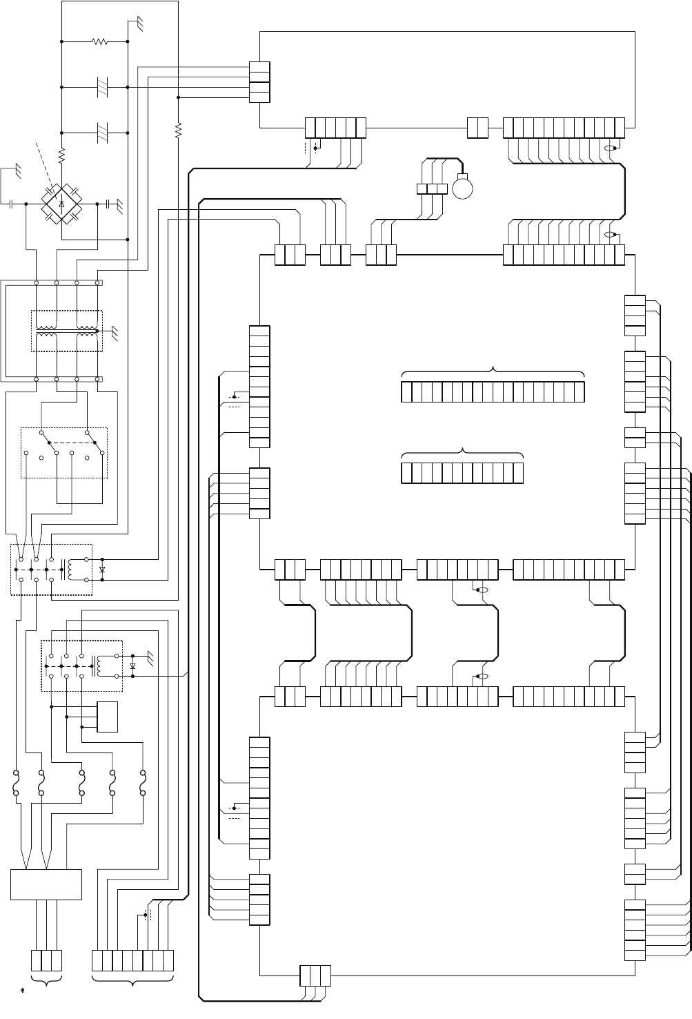
1
2
3
4
5
6
7
8
9
10
11
1
2
3
4
5
6
7
8
1
2
3
4
5
6
7
8
1
2
3
1
2
3
4
5
6
1
2
1
2
3
4
5
6
1
2
3
4
1
2
3
4
5
6
7
8
9
10
11
12
1
2
3
4
5
1
2
3
J1118
HMCNT
+15V
E
+12V
+15V
E
E
10V
-15V
10VE
+5V
BS2
BS3
BS1
TNC
VDINE
MICPS
VDIN
+5V
GS
MONI
GSE
TGT
TNL
TGTE
-15V
TNI
J1103
J1109
J1110
PC1101
CMC-1205V
T/R CONTROL CIRCUIT
+15V
E
TRG2
TIYE
TIY
BP
BPE
BZE
BZ
J1
FAI_Z
E
+12V
J1105
J13
J2
FAI_ZE
FAI_A
FAI_B
C2
+12V
VDE
VD
MTR-
MTR+
+12V
E
ALM
J1113
1
2
3
4
5
6
7
8
9
10
11
1
2
3
4
5
6
7
8
1
2
3
4
5
6
7
8
1
2
3
1
2
3
4
5
6
1
2
1
2
3
4
5
6
1
2
3
4
1
2
3
4
5
6
7
8
9
10
11
12
1
2
3
4
5
J6118
HMCNT
+15V
E
+12V
+15V
E
E
10V
-15V
10VE
+5V
BS2
BS3
BS1
TNC
VDINE
MICPS
VDIN
+5V
GS
MONI
GSE
TGT
TNL
TGTE
-15V
TNI
J6103
J6109
J6110
PC610
CMH-2081
INTERFACE CIRCUIT
+15V
E
TRG2
TIYE
TIY
BP
BPE
BZE
BZ
J6001
J6105
J6013
J6002
C2
NC
MTR-
MTR+
1
2
3
+12V
E
ALM
J6113
1
2
3
PWR+
PWR-
J615
1
2
3
+24V
E
ALM
J619
H-7ZCRD1154
W619
FAN
H-7ZCRD1165
W6118
H-7ZCRD1158
W6103
H-7ZCRD1161
W6109
H-7ZCRD1162
W6110
H-7ZCRD1156W6002
H-7ZCRD1157W6013
H-7ZCRD1159W6105
H-7ZCRD1155W6001
H-7ZCRD1163W6111
H-7ZCRD1160W6106
H-7ZCRD1164W6113
MAGI
SHORT
X1
X2
TIE
TI
+15V
E
J1111
NC
NC
NC
NC
PW2
PW1
PW3
+24V
E
J1106
MAGI
SHORT
X1
X2
TIE
TI
+15V
E
J6111
PW2
PW1
PW3
+24V
E
J6106
1
2
3
+24V
E
+15V
J614
4
5
6
7
8
9
10
11
E
E
+12V
-15V
OP
TISTOP
E
TI
12TIE
1
2
3
+24V
E
+15V
J621
4
5
6
7
8
9
10
11
E
E
+12V
-15V
OP
TISTOP
E
TI
12 TIE
1
2
3
MH
MN
J624
4
5
6
OP
65E
65
RED
PUR
RED.T
BLU.T
YEL
1
2
3
4
100E
100V
AC12V
AC12V
J622
1
2TIE
TI
J623
BLK.T
RED.T
ORN.T
ORN.T
470 8W
R604
22k 2W
R603
4700uF
160V
C602+
4700uF
160V
C601+
F.G.
25 4W
RX601
C604C603
C605 C606
F.G.
F.G.
F.G.
12
34
56
78
BRN.T
BRN.T
OFF
200V
WHT.T
S601
GRN.T
WHT
WHT
12
34
910
WHT.T
OFF
200V
GRN
CD601
BLK.T
RED.T
WHT
GRN
K601
GZ601
78
F.G.
21
10 9
43
CD602
K602
78
FL601
WHT.T
GRN
GRN.T
ORN.T
WHT
2
4
6
1
3
5
U
V
W
TB601 WHT.T
GRN.T
ORN.T
U2
V2
W2
TB602
MN
MH
65
65E
WHT.T
GRN.T
ORN.T
RED.T
BLU.T
YEL
W14
C608
C607
CD603
S25VB40
T601
7LVR0069
7A DELAY
7A DELAY
3.15A
RED
109P0424H302
B601
BLK
YEL
1
2
3
+15V
-15V
VD
TB612
4
5
6
7
8
9
10
11
VDE
TI
MO
TIE
PW
TNI
TNC
C2
12BP
13
14
15
16
17
BPE
BZ
REV
E
E
18E
1
2
3
TRX+
TRX-
VD
TB612
4
5
6
7
8
9
10
11
VDE
TRGE
TRG
BP
BPE
BZ
BZE
COM+
12COM-
RED
BLK
YEL
RED
BLK
YEL
pressure bonding
P601/J601
WHT.T
WHT.T
WHT.T
WHT.T
WHT.T
WHT.T
WHT.T
WHT.T
F601
F602
F603
F604
F605
To SCANNER UNIT
To DISPLAY UNIT
To SCANNER UNIT To AC 220-240V 3
RED
BLK
BLK
BLK
BLK
ORN
GRN
PUR
YEL
WHT
RED
BLK
BLK
BLK
BLK
ORN
GRN
PUR
YEL
WHT
3.15A
7A DELAY
GRN.T
PC620
CBA-204B
AVR CIRCUIT
FAI_Z
E
FAI_ZE
FAI_A
FAI_B
P1113
P1111
P1106
P1118
P1103
P1109
P1110
P1
P1105
P13
P2
P6118
P6103
P6109
P6110
P6001
P6105
P6013
P6002
P6113
P615
P619
P614
P6111
P6106
P621
P624
P622
W16 W16
Fig.13 Internal Connection Diagram of POWER UNIT, Type NBL-315
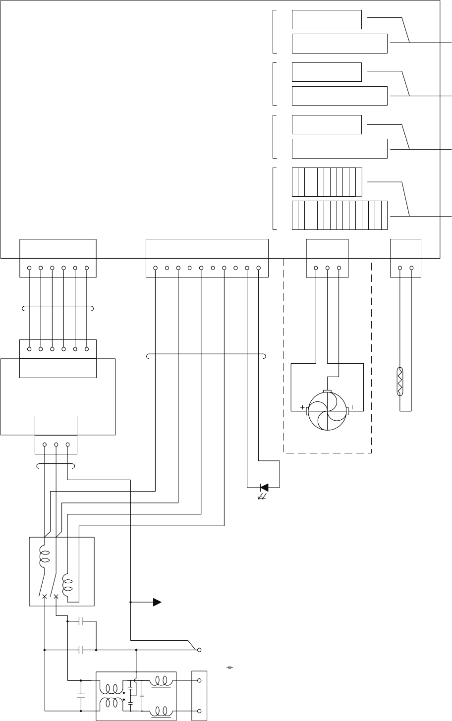
11.MTROUTE
10.MTROUT-
9.MTROUT+
8.BZOUTE
7.BZOUT
5.BPOUT
6.BPOUTE
2.VDOUTE
3.TRGOUT
4.TRGOUTE
1.VDOUT
15.PWROUTE
14.PWROUT
13.RWRINE
12.PWRIN
11.MTRINE
9.MTRIN+
10.MTRIN-
6.BPINE
7.BZIN
8.BZINE
5.BPIN
4.TRGINE
3.TRGIN
2.VDINE
1.VDIN
CH-1
TB 911 TB 912 TB 913 TB 914 TB 915 TB 916 TB 917 TB 918
1
2
CCL-304
TO
DISPLAY1
TO
DISPLAY2
TO
DISPLAY3
CH-2 CH-3 CH-4
3
J903
1
2
3
4
5
6
1
2
3
4
5
6
7
8
9
10
J904
J905
1
2
J909
-15V
GND
GND
GND
5 V
+15V
AC(L)
AC(N
)
TRTP+
E
POWLED
TRTP-
FANV
FANE
FANPLS
1
2
3
4
5
6
-15V
GND
GND
GND
5 V
+15V
P903P902
1
3
5
AC(L)
AC(N
)
FG
S
P904
P905
P909
CN2
CN1P901
LOAD
B
C
D
A
LINE
12
34
UV
E
TB901
AC100/110/115/220/
230/240V 50/60Hz 1
TE901
FG
CD901
R901
H-7ZCRD0920
H-7ZCRD0921
H-7ZCRD0919
CBA-357
B901
CB901
C901 C902 C903
LF901
TO
DISPLAY4
Fig.14 Internal Connection Diagram of
INTERSWITCH UNIT, Type NQE-3141
(Option)
Fig.15 Over View of RADAR Menu
With PLOTTER Unit (option)
MAIN MENU(RADAR MENU key)
1RADAR Trails Setting -1 Trails Mode → Section 3.8.2
2 Trails Reference Level → Section 3.8.2
3 Trails Reduction → Section 3.8.2
5 Trails Process → Section 3.8.2
6 Max Interval → Section 3.8.2
7 Trails Erase -1 Trails Erase Mode → Section 3.4.9
2 Trails Erase Start → Section 3.4.9
3 Eraser Size → Section 3.4.9
8 File Operations -1 Select Card Slot → Section 3.4.10
2 Load → Section 3.4.10
3 Save → Section 3.4.10
4 Erase → Section 3.4.10
2Map Setting -1 Fill Land Area → Section 3.12.4
2 C-MAP Setting -1 LAT/LON Line Display → Section 3.12.6
2 Depth Display → Section 3.12.6
3 Depth Unit → Section 3.12.6
4 Light Sectors Display → Section 3.12.6
5 Light Sectors Level → Section 3.12.6
6 Chart Boundary → Section 3.12.6
7 Buoy&Beacon → Section 3.12.6
8 Names → Section 3.12.6
9 Next
↓
1 Land Marks → Section 3.12.6
2 River&Lake → Section 3.12.6
3 Cultual → Section 3.12.6
4 Bottom Type → Section 3.12.6
5 Under Water → Section 3.12.6
6 Depth Contour → Section 3.12.6
3 JRC/ERC Setting -1 Day/Night → Section 3.12.5
2 Color of Land → Section 3.12.5
3 Bright of Land → Section 3.12.5
4 Color of Sea → Section 3.12.5
5 Bright of Sea → Section 3.12.5
6 Color of Name → Section 3.12.5
7 Bright of Name → Section 3.12.5
8 Bright of Track/Mark/Line → Section 3.12.5
9 Next
↓
1 LAT/LON Line → Section 3.12.5
2 Color of L/L Line → Section 3.12.5
3 Bright of L/L Line → Section 3.12.5
4 ERC Display Request → Section 3.12.5
5 ERC Mark → Section 3.12.5
6 JRC ROM Card Display -1 Lighthouse → Section 3.12.5
2 Buoy → Section 3.12.5
3 Rough Line → Section 3.12.5
4 Other Line → Section 3.12.5
7Copy JRC ROM Card to CF → Section 3.12.3
8 Fishing Area Display
4 Contour Setting -1 10m → Section 3.12.5
2 20m → Section 3.12.5
3 30m → Section 3.12.5
4 40m → Section 3.12.5
5 50m → Section 3.12.5
6 60m → Section 3.12.5
7 70m → Section 3.12.5
8 80m → Section 3.12.5
9 Other → Section 3.12.5
5 Map Display Setting -1 Shift Coast Line 1 → Section 3.12.7
2 Shift Coast Line 2 → Section 3.12.7
3 LAT/LON Correction → Section 3.12.7
4 Map Center Position → Section 3.12.7
5 LORAN C Correction -1 Chain
2 TD1
3 TD2
4 TD1 Correction
5 TD2 Correction
6 LORAN A Correction -1 LOP1
2 LOP2
3 TD1 Correction
4 TD2 Correction
7 DECCA Correction -1 Chain
2 LOP1
3 LOP2
4 LOP1 Correction
5 LOP2 Correction
6 SEL JRC ROM Card File → Section 3.12.3
7 Map Draw AZI Mode → Section 3.12.8
8 JRC Card Draw Mode → Section 3.12.5

MAIN MENU(RADAR MENU key)
3TOOL Menu -1PI Menu -1 Display for All Lines → Section 4.1.5
2 Operation Mode → Section 4.1.5
3 Control → Section 4.1.5
The setting items are
determined by the setting
of Operation Mode
All:
Individual:
Track:
Equiangular:
4 Floating → Section 4.1.5
5 Heading Link → Section 4.1.5
6 Next
PI Bearing
Interval
8Press EBL Dial
to Control PI#
Displayed only when
"Control" is Individual.
9Press VRM Dial
to Move End Point#
↓
1 Range Scale Link → Section 4.1.5
2 Reference Bearing → Section 4.1.5
The setting items are
determined by the setting
of Operation Mode
All:
Individual:
Track:
Equiangular:
3 Operation Area → Section 4.1.5
4 Display for Individual Line -1 Index Line 1 → Section 4.1.5
2 Index Line 2 → Section 4.1.5
PI Bearing 3 Index Line 3 → Section 4.1.5
Interval 4 Index Line 4 → Section 4.1.5
5 Index Line 5 → Section 4.1.5
6 Index Line 6 → Section 4.1.5
7 Index Line 7 → Section 4.1.5
8 Index Line 8 → Section 4.1.5
8Press EBL Dial
to Control PI#
9Press VRM Dial
to Move End Point#
Displayed only when
"Control" is Individual.
2 Rectangle Cursor -1 Rectangle Cursor Display
2 Make Rectangle Cursor
3 Ent
4 Unit of Distance
3 EBL Maneuver Setting -1 EBL Maneuver → Section 4.1.6
2 Reach → Section 4.1.6
3 Turn Mode → Section 4.1.6
4 Turn Set → Section 4.1.6
4 Trial Maneuver -1 Trial Function → Section 5.7
2 Course(EBL) → Section 5.7
3 Speed(VRM) → Section 5.7
4 Vector Time → Section 5.7
5 Time to Maneuver → Section 5.7
6 Own Ship's Dynamic Trait -1 Reach → Section 5.7
2 Turn Radius → Section 5.7
3 Acceleration → Section 5.7
4 Deceleration → Section 5.7
4 TARGET TRACK Setting -1 Target Track Function → Section 5.6.2
(T.TRK) 2 Target Track Color -1 All → Section 5.6.2
2 Target Track No.1 → Section 5.6.2
3 Target Track No.2 → Section 5.6.2
4 Target Track No.3 → Section 5.6.2
5 Target Track No.4 → Section 5.6.2
6 Target Track No.5 → Section 5.6.2
7 Target Track No.6 → Section 5.6.2
8 Target Track No.7 → Section 5.6.2
9 Next
↓
1 Target Track No.8 → Section 5.6.2
2 Target Track No.9 → Section 5.6.2
3 Target Track No.10 → Section 5.6.2
4 Other → Section 5.6.2
3 Target Track Display -1 All → Section 5.6.2
2 Target Track No.1 → Section 5.6.2
3 Target Track No.2 → Section 5.6.2
4 Target Track No.3 → Section 5.6.2
5 Target Track No.4 → Section 5.6.2
6 Target Track No.5 → Section 5.6.2
7 Target Track No.6 → Section 5.6.2
8 Target Track No.7 → Section 5.6.2
9 Next
↓
1 Target Track No.8 → Section 5.6.2
2 Target Track No.9 → Section 5.6.2
3 Target Track No.10 → Section 5.6.2
4 Other
4 Track Memory Interval → Section 5.6.2
5 Clear Track Color → Section 5.6.2
6 Clear Track Number → Section 5.6.2
7 File Operations -1 Select Card Slot → Section 5.6.2
2 Load Mode → Section 5.6.2
3 Load → Section 5.6.2
4 Save → Section 5.6.2
5 Erase → Section 5.6.2
6 Card T.TRK Display → Section 5.6.2
MAIN MENU(RADAR MENU key)
5AZ Menu -1 AZ 1 → Section 5.2.1
2 AZ 2 → Section 5.2.1
3 Make AZ -1 Make AZ 1 → Section 5.2.1
2 Make AZ 2 → Section 5.2.1
3 ENT
4 RADAR Alarm -1 Sector RADAR Alarm -1 Sector Alarm 1 → Section 3.4.24
2 Sector Alarm 2 → Section 3.4.24
3 Make Sector Alarm -1 Sector Alarm 1 → Section 3.4.24
2 Sector Alarm 2 → Section 3.4.24
3 ENT
5 RADAR Alarm Mode → Section 3.4.24
6 Sensitivity Level → Section 3.4.24
5 Set AZ Key -1AZ -1 AZ 1 → Section 5.2.1
2 AZ 2 → Section 5.2.1
2 Sector RADAR Alarm -1 Sector Alarm 1 → Section 3.4.24
2 Sector Alarm 2 → Section 3.4.24
6 Own Track Menu -1 DISP Own Track → Section 3.5.1
(O.TRK) 1 DISP Own Track Color -1 All
2 White
3 Cyan
4 Blue
5 Green
6 Yellow
7 Pink
8 Red
2 Clear Own Track → Section 3.5.4
2 Clear Own Track Color
3 Track Type
4 Num/Vector Display
5 File Operations -1 Select Card Slot → Section 3.5.5
2 Load Mode → Section 3.5.5
3 Load → Section 3.5.5
4 Save → Section 3.5.5
5 Erase → Section 3.5.5
6 Card Own Track Display → Section 3.5.5
6 Water Depth Setting -1 Depth setting (MIN)
2 Depth setting
3 Depth setting
4 Depth setting
5 Depth setting
6 Depth setting (MAX)
7 Water TEMP. Setting -1 Temperature setting (MIN)
2 Temperature setting
3 Temperature setting
4 Temperature setting
5 Temperature setting
6 Temperature setting (MAX)
8 Current Setting -1 Current Size
2 Layer A
3 Layer B
4 Layer C

MAIN MENU(RADAR MENU key)
7PLOT Menu -1 Mark Setting -1 Display Mark Type -1 All → Section 3.6.2
2○ → Section 3.6.2
3△ → Section 3.6.2
4▽ → Section 3.6.2
5□ → Section 3.6.2
6◇ → Section 3.6.2
7wreck (mark) → Section 3.6.2
8△△ → Section 3.6.2
9 Next
↓
1▽▽ → Section 3.6.2
2△▽ → Section 3.6.2
3▽△ → Section 3.6.2
4+ → Section 3.6.2
5× → Section 3.6.2
6Y → Section 3.6.2
7hand drum (mark) → Section 3.6.2
8light house (mark) → Section 3.6.2
9 Next
↓
1trapezoid(mark) → Section 3.6.2
2filled trapezoid(mark) → Section 3.6.2
3hat(mark) → Section 3.6.2
4●● → Section 3.6.2
5● → Section 3.6.2
6filled triangle(mark) → Section 3.6.2
7! → Section 3.6.2
8anchor(mark) → Section 3.6.2
9 Next
↓
1slash-anchor(mark) → Section 3.6.2
2circle-dotted line(mark) → Section 3.6.2
3non-dangerous wreck(mark) → Section 3.6.2
4◎ → Section 3.6.2
5mariner's event mark(mark) → Section 3.6.2
6・ → Section 3.6.2
7wavy line (mark) → Section 3.6.2
8solid line (mark) → Section 3.6.2
9 Next
↓
1dashed-dotted line (mark) → Section 3.6.2
2 Display Mark Color -1 All → Section 3.6.2
2 White → Section 3.6.2
3 Cyan → Section 3.6.2
4 Blue → Section 3.6.2
5 Green → Section 3.6.2
6 Yellow → Section 3.6.2
7 Pink → Section 3.6.2
8 Red → Section 3.6.2
3 File Operations -1 Select Card Slot → Section 3.6.6
2 Load Mode → Section 3.6.6
3 Load → Section 3.6.6
4 Unload → Section 3.6.6
5 Save → Section 3.6.6
6 Erase → Section 3.6.6
7 Card Mark Display → Section 3.6.6
4 Select Mark Size → Section 3.6.2
5 Comment Font Size → Section 3.6.2
2 Mark Operations -1 Own Ship Position → Section 3.6.3
2 Edit User Map -1 Make with Cursor -1 Type → Section 3.6.1
2 Color → Section 3.6.1
2 Make with L/L -1 Type → Section 3.6.1
2 Color → Section 3.6.1
3 L/L → Section 3.6.1
4 Comment → Section 3.6.1
5 Enter → Section 3.6.1
9 New Line Input → Section 3.6.1
⇔
New Mark Input → Section 3.6.1
3 Move → Section 3.6.3
4 Delete → Section 3.6.3
5 Insert/Move Vertex → Section 3.6.3
6 Delete Vertex → Section 3.6.3
7 Delete by Type by Color → Section 3.6.3
3 Shift → Section 3.6.5
4 Shift Clear → Section 3.6.5
5 Mark/Line Entry → Section 3.6.4
6 Mark/Line List → Section 3.6.4
7 Geodetic → Section 3.6.7
MAIN MENU(RADAR MENU key)
7PLOT Menu -3 WPT/Route Settig -1 Waypoint Alarm
(Route Type:Plotter)2 Route Alarm
3 Set Route Sequence
4 Select Route
5 Waypoint Entry
6 Waypoint Input
7 Save Temporary Route
8 Cross Track Limit Line
9 Next
↓
1 Select WPT Mark Size
2 Waypoint Vector
3 Status of Origin/DEST
4 WPT Number Display
5 RTE Number Display
4 WPT/Route Operation -1 Route Sequence
2 Waypoint Switch Mode
3 Waypoint Skip
4 Waypoint Back Skip
5 Set/Cancel Waypoint
5 Clear Memory -1 Clear Mark/Line Data → Section 3.6.2
2 Clear WPT/Route Data
6 Plot Setting -1 Scale/Course Up Setup -1 Scale
2 Preset Scale
3 Course Up Data -1 Tolerance
2 Averaging
3 Round Speed
2 Current Position Display
3 Cursor Vector DISP
4 Cursor HL Length
5 Scalebar Display
6 AUTO Backup
7 NMEA Waypoint Display → Section 3.7.1
9 Next
Press RADAR MENU again
1 File Manager → Section 3.11.1
2 RADAR Menu -1 Process Setting -1 Video Latitude → Section 3.8.1
2 Video Noise Rejection → Section 3.8.1
3 AUTO Dynamic Range → Section 3.8.1
4 Process Switch → Section 3.8.1
5 2nd Process Mode → Section 3.8.1
6 Process Switch Range → Section 3.8.1
7 Fast Target Detection → Section 3.8.1
8 User Function Setting -1 Function1 Setting -1 Mode → Section 3.9.3
2IR → Section 3.9.3
3 Process → Section 3.9.3
4 Target Enhance → Section 3.9.3
5 AUTO Sea/Rain → Section 3.9.3
6 Save Present State → Section 3.9.3
9 Next
↓
1 Pulse Length 0.75nm → Section 3.9.3
2 Pulse Length 1.5nm → Section 3.9.3
3 Pulse Length 3/4nm → Section 3.9.3
4 Pulse Length 6/8nm → Section 3.9.3
5 Pulse Length 12nm → Section 3.9.3
6 Pulse Length 16nm → Section 3.9.3
9 Next
↓
1 Video Latitude → Section 3.9.3
2 Video Noise Rejection → Section 3.9.3
3 AUTO Dynamic Range → Section 3.9.3
4 Process Switch → Section 3.9.3
5 2nd Process Mode → Section 3.9.3
6 Process Switch Range → Section 3.9.3
7 Fast Target Detection → Section 3.9.3
9 Next
↓
1 Trails Interval → Section 3.9.3
2 Trails Mode → Section 3.9.3
3 Trails Reference Level → Section 3.9.3
4 Trails Reduction → Section 3.9.3
5 Time/All Combine → Section 3.9.3
6 Trails Process → Section 3.9.3
7 Max Interval → Section 3.9.3
9 Next → Section 3.9.3
↓
1 Gain Offset → Section 3.9.3
2 PRF → Section 3.9.3
3 Small Buoy Detection → Section 3.9.3
4 Fishnet Detection → Section 3.9.3
5 Antenna Height → Section 3.9.3
8 Set Mode Default → Section 3.9.3
9 Initialize → Section 3.9.3
2 Function2 Setting → Section 3.9.3
3 Function3 Setting → Section 3.9.3
4 Function4 Setting → Section 3.9.3
9 SART → Section 6.5

MAIN MENU(RADAR MENU key)
-> Press RADAR MENU again
2 RADAR Menu -3 TXRX Setting -1 PRF Fine Tuning → Section 3.8.3
2 Stagger Trigger → Section 3.8.3
4 PRF
5 Ice Class Standby Mode → Section 3.8.3
3 Multi Window Setting -1 DIR/DIST EXP Display → Section 3.8.8
2 Numeric NAV INFO → Section 3.8.8
3 Depth Graph Setting -1 Depth Graph Display → Section 3.8.8
2 Depth Range → Section 3.8.8
3 Time Range → Section 3.8.8
4 Depth Unit → Section 3.8.8
4 Wind Graph -1 Wind Graph Display → Section 3.8.8
2 Wind Speed Unit → Section 3.8.8
5 TEMP Graph Setting -1 TEMP Graph Display → Section 3.8.8
2 TEMP Graph Color → Section 3.8.8
3 TEMP Range -1 Temperature setting (MIN) → Section 3.8.8
2 Temperature setting → Section 3.8.8
3 Temperature setting → Section 3.8.8
4 Temperature setting → Section 3.8.8
5 Temperature setting → Section 3.8.8
6Temperature setting (MAX) → Section 3.8.8
4 Time Range → Section 3.8.8
6 Course Bar Setting -1 Course Bar Display → Section 3.8.8
2 Autopilot Course → Section 3.8.8
3 ROT Scale → Section 3.8.8
4 NAV Equipment Setting -1 GYRO Setting → Section 3.4.16 → Section 7.1.7
2 MAG Compass Setting -1 Heading Correction → Section 3.4.18
2 Correct Value → Section 3.4.18
3 Set/Drift Setting -1 Correction → Section 3.4.19
2 Set → Section 3.4.19
3 Drift → Section 3.4.19
4 GPS Setting -1 GPS Process Setting -1 Position → Section 3.4.20
2 Exclusion → Section 3.4.20
3 Geodetic → Section 3.4.20
4 Antenna Height → Section 3.4.20
5 Fix Mode → Section 3.4.20
6 DOP Level → Section 3.4.20
7 Position Average → Section 3.4.20
8 Master Reset → Section 3.4.20
9 Send Data → Section 3.4.20
2 DGPS Setting -1 Mode → Section 3.4.21
2 Frequency → Section 3.4.21
3 Baud Rate(BPS) → Section 3.4.21
4 DGPS Mode → Section 3.4.21
5 Send Data → Section 3.4.21
3 SBAS Setting -1 Mode → Section 3.4.22
2 Ranging → Section 3.4.22
3 NG SBAS → Section 3.4.22
4 SBAS Select Mode → Section 3.4.22
5 SBAS No. → Section 3.4.22
6 Send Data → Section 3.4.22
4 GPS Status → Section 3.4.23
5 Weather INFO Setting -1 Display Weather INFO
2 SEL Observation Place
3 RX Message Display
4 RX Buzzer

MAIN MENU(RADAR MENU key)
-> Press RADAR MENU again
5 Sub Menu -1 Display Color Setting -1 Day/Night → Section 3.8.5
2 Outer PPI → Section 3.8.5
3 Inner PPI → Section 3.8.5
4 Character → Section 3.8.5
5 RADAR Video → Section 3.8.5
6 RADAR Trails(Time) → Section 3.8.5
7 RADAR Trails(All) → Section 3.8.5
8 Target Symbol → Section 3.8.5
9 Next → Section 3.8.5
↓
1 Cursor → Section 3.8.5
2 Range Rings → Section 3.8.5
3 EBL/VRM/PI → Section 3.8.5
4 Own Symbol/HL/Vector → Section 3.8.5
2 Brilliance Setting -1 RADAR Video → Section 3.8.5
2 RADAR Trails → Section 3.8.5
3 Target Symbol → Section 3.8.5
4 Range Rings → Section 3.8.5
5 EBL/VRM/PI → Section 3.8.5
6 Character → Section 3.8.5
7 Own Symbol/HL/Vector → Section 3.8.5
8 Keyboard → Section 3.8.5
3 User Setting -1 Load User Setting → Section 3.10.2
2 Save User Setting → Section 3.10.1
3 Delete User Setting → Section 3.10.3
4 User Key Setting -1 User Key 1 → Section 3.8.7
2 User Key 2 → Section 3.8.7
5 Buzzer Volume -1 Key ACK → Section 3.8.6
2 OPE Miss → Section 3.8.6
3 CPA/TCPA Alarm → Section 3.8.6
4 New Target Alarm → Section 3.8.6
5Lost Alarm → Section 3.8.6
6 Navigation Alarm → Section 3.8.6
7 System Alarm → Section 3.8.6
8 Inter Switch → Section 3.8.6
6 Date/Time Setting -1 UTC/LMT → Section 7.2.7
2 LMT Date → Section 7.2.7
3 LMT Time → Section 7.2.7
4 Time Zone → Section 7.2.7
5 Display Style → Section 7.2.7
6 Synchronize with GPS → Section 7.2.7
7 Screen Capture Setting -1 Select Item -1 Graphic → Section 3.13.4
2 RADAR Video → Section 3.13.4
3 RADAR Trails → Section 3.13.4
4 Chart → Section 3.13.4
2 Select Card Slot → Section 3.13
3 File Erase → Section 3.13.3
4 AUTO Capture Interval → Section 3.13.2
5 AUTO File Erase → Section 3.13.2
9 EBL/Cursor Setting -1 EBL1 Bearing Fix → Section 4.1.3
2 EBL2 Bearing Fix → Section 4.1.3
3 Cursor Setting -1 EBL/VRM Control CURS → Section 3.8.4
2 Cursor Length → Section 3.8.4
4 Cursor Pattern → Section 3.8.4
6 TT Menu -1 Association Setting -1 Association → Section 5.4
2 Priority → Section 5.4
3 Bearing → Section 5.4
4 Range → Section 5.4
5 Course → Section 5.4
6 Speed → Section 5.4
7Applicable AIS Target → Section 5.4
3 Trial Maneuver -1 Trial Function → Section 5.7
2 Course(EBL) → Section 5.7
3 Speed(VRM) → Section 5.7
4 Vector Time → Section 5.7
5 Time to Maneuver → Section 5.7
6 Own Ship's Dynamic Trait -1 Reach → Section 5.7
2 Turn Radius → Section 5.7
3 Acceleration → Section 5.7
4 Deceleration → Section 5.7
4 Target Number Display → Section 5.2.4
9 TT Test Menu -1 Test Video → Section 5.2.7
2 TT Simulator → Section 5.2.7
3 Status → Section 5.2.7
4 Gate Display → Section 5.2.7
MAIN MENU(RADAR MENU key)
-> Press RADAR MENU again
7 AIS Menu -1 Association Setting -1 Association → Section 5.4
2 Priority → Section 5.4
3 Bearing → Section 5.4
4 Range → Section 5.4
5 Course → Section 5.4
6 Speed → Section 5.4
7 Applicable AIS Target → Section 5.4
3 Trial Maneuver -1 Trial Function → Section 5.7
2 Course(EBL) → Section 5.7
3 Speed(VRM) → Section 5.7
4 Vector Time → Section 5.7
5 Time to Maneuver → Section 5.7
6 Own Ship's Dynamic Trait -1 Reach → Section 5.7
2 Turn Radius → Section 5.7
3 Acceleration → Section 5.7
4 Deceleration → Section 5.7
4 AIS Filter Setting -1 Filter Type → Section 5.3.7
2 Make AIS Filter → Section 5.3.7
3 Filter Display → Section 5.3.7
4 ENT
6 Filter Mode → Section 5.3.7
5 Target Number Display → Section 5.3.6
6 AIS Alarm Setting -1 Lost Alarm → Section 5.3.9
2 CPA/TCPA Alarm → Section 5.3.9
7 Message -1 Addressed Message → Section 5.3.5
2 Broadcast Message → Section 5.3.5
8 Display Lost TGT Data → Section 5.3.5
9 Own Ship's AIS Data → Section 5.3.5
8 Multi Dial Setting -1 Vector Time → Section 3.3.6
2 Trails Length → Section 3.3.6
3 TT Display No. → Section 3.3.6
4 C-UP Angle → Section 3.3.6
5 Own Track Color
6 Mark/Line Color → Section 3.3.6
7 Manual Tune → Section 3.3.6
9 Test Menu -1 Self Test -1 Memory Test -1 SDRAM → Section 8.3.1
2 SRAM → Section 8.3.1
3 FLASH ROM → Section 8.3.1
4 GRAPHIC → Section 8.3.1
2 TXRX Test → Section 8.3.1
3 Line Test → Section 8.3.1
4 Supply Voltage → Section 8.3.1
2 Monitor Test -1 Pattern 1 → Section 8.3.1
2 Pattern 2 → Section 8.3.1
3 Pattern 3 → Section 8.3.1
4 Pattern 4 → Section 8.3.1
5 Pattern 5 → Section 8.3.1
6 Pattern 6 → Section 8.3.1
7 Pattern 7 → Section 8.3.1
8 Pattern 8 → Section 8.3.1
3 Keyboard Test -1 Key Test → Section 8.3.1
2 Buzzer Test → Section 8.3.1
3 Light Test → Section 8.3.1
4 MON Display
5 System Alarm Log → Section 8.3.1
6 System Information → Section 8.3.1
0 EXIT

Serviceman Menu → Section 7.1.1
1 Adjust Menu -1 Tune Adjustment → Section 7.1.3
2 Bearing Adjustment → Section 7.1.4
3 Range Adjustment → Section 7.1.5
4 TXRX Adjustment -1 Antenna Height → Section 7.1.8
2 Tune Peak Adjustment → Section 7.1.3
3 Tune Indicator Adjust → Section 7.1.3
4 MON Adjustment
5 MON Indicator Adjustment
6 Output Pulse → Section 7.2.4
2 Installation Menu -1 Installation Information -1 Date → Section 7.2.8
2 Name → Section 7.2.8
3 Company → Section 7.2.8
2 Master/Slave → Section 7.2.5
3 Sector Blank -1 Sector1 → Section 7.2.2
2 Sector2 → Section 7.2.2
3 Sector3 → Section 7.2.2
4 Make Sector1 → Section 7.2.2
5 Make Sector2 → Section 7.2.2
6 Make Sector3 → Section 7.2.2
4 CCRP Setting → Section 7.1.9
5 COM Port Setting -1 Baud Rate -1 COMPASS → Section 7.2.1
2 NAV1 → Section 7.2.1
3 NAV2 → Section 7.2.1
4 GPS → Section 7.2.1
5 NMEA → Section 7.2.1
2 RX Port -1 GPS → Section 7.2.1
2 DLOG → Section 7.2.1
3 Alarm → Section 7.2.1
4 Depth → Section 7.2.1
5 Temperature → Section 7.2.1
6 Wind → Section 7.2.1
7 Current → Section 7.2.1
8 ROT → Section 7.2.1
9 Next
↓
1 RSA → Section 7.2.1
3 RX Sentence -1 GPS(LL/COG/SOG) → Section 7.2.1
2 GPS(WPT/TIME) → Section 7.2.1
3 Depth → Section 7.2.1
4 Wind → Section 7.2.1
5 Current -1 Data Set Number → Section 7.2.1
2 Layer A → Section 7.2.1
3 Layer B → Section 7.2.1
4 Layer C → Section 7.2.1
4 TX Port -1 TTM(TT) → Section 7.2.1
2 TLL(TT) → Section 7.2.1
3 TTD(TT) → Section 7.2.1
4 TLB(TT) → Section 7.2.1
5 OSD → Section 7.2.1
6 RSD → Section 7.2.1
7 ALR → Section 7.2.1
8 ACK → Section 7.2.1
9 Next
↓
1 TTM(AIS) → Section 7.2.1
2 TLL(AIS) → Section 7.2.1
3 TTD(AIS) → Section 7.2.1
4 TLB → Section 7.2.1
5 Remote Maintenance → Section 7.2.1
6 JRC-ARPA → Section 7.2.1
7 NMEA0183 Output Format → Section 7.2.1
8 NMEA0183 Talker → Section 7.2.1
9 Next
↓
1 NMEA0183 TX Interval → Section 7.2.1
2 APB → Section 7.2.1
3 BOD → Section 7.2.1
4 GGA → Section 7.2.1
5 GLL → Section 7.2.1
6 RMC → Section 7.2.1
7 RMB → Section 7.2.1
8 VTG → Section 7.2.1
9 Next
↓
1 XTE → Section 7.2.1
2 BWC → Section 7.2.1
3 HDT → Section 7.2.1
4 THS → Section 7.2.1
5 Select NAV Equipment → Section 7.2.1
7 Line Monitor -1 COMPASS
2 NAV1
3 NAV2/ARPA
4 GPS
5 NMEA
6 TXRX/ISW
7 KEYBOARD1
8 KEYBOARD2

Serviceman Menu → Section 7.1.1
2 Installation Menu 6 Alarm System -2 Relay Output -1 Relay Output Mode → Section 7.2.9
2 TT CPA/TCPA → Section 7.2.9
3 AIS CPA/TCPA → Section 7.2.9
4 New Target → Section 7.2.9
5 Lost → Section 7.2.9
6 RADAR Alarm → Section 7.2.9
3 ALR Output -1 System Alarm → Section 7.2.9
2 TT/AIS Alarm → Section 7.2.9
5 External ACK Setting -1 Critical Alarm -1 Audio → Section 7.2.9
2 Indication → Section 7.2.9
3 Acknowledge State → Section 7.2.9
2 Normal Alarm -1 Audio → Section 7.2.9
2 Indication → Section 7.2.9
3 Acknowledge State → Section 7.2.9
7 Inter Switch -1 ISW Install
2 Mask Setting -1 No.1 Connection
No.1 Master
2 No.2 Connection
No.2 Master
3 No.3 Connection
No.3 Master
4 No.4 Connection
No.4 Master
5 No.5 Connection
No.5 Master
6 No.6 Connection
No.6 Master Only for ISW Extended Mode
7 No.7 Connection
No.7 Master
8 No.8 Connection
No.8 Master
3 S-ISW TXRX Power Supply
8 Language → Section 7.2.6
9 Next
↓
1 Input BP Count → Section 7.2.5
2 TNI Blank -1 TNI Blank → Section 7.2.3
2 Make Sector → Section 7.2.3
3 Device Installation -1 Gyro → Section 7.1.6
2 Compass → Section 7.1.6
3 GPS Compass → Section 7.1.6
4 LOG → Section 7.1.6
5 2AXW → Section 7.1.6
6 2AXG → Section 7.1.6
7 GPS → Section 7.1.6
2 Installation Menu -9 Next
↓
4 Network - 1 Network Function → Section 7.2.10
2IP Address
4Synchronization - 1 Day/Night → Section 7.2.10
2 Keyboard → Section 7.2.10
3 Maintenance Menu -1 Safety Switch → Section 7.4.1
2 Area Initial -1 Partial Master Reset -1 Serviceman Menu → Section 7.4.2
2 Except Serviceman Menu → Section 7.4.2
3 User Setting → Section 7.4.2
4 TT Setting → Section 7.4.2
5 AIS Setting → Section 7.4.2
6 Day/Night → Section 7.4.2
7 JRC Card Copy Record → Section 7.4.2
2 All Master Reset → Section 7.4.2
3 Internal To Card 1/2 → Section 7.4.3
4 Card 1/2 To Internal → Section 7.4.3
5 TXRX Time -1 Clear TX Time → Section 7.4.4
2 Clear Motor Time → Section 7.4.4
3 TXRX to Display Unit → Section 7.4.4
4 Display Unit to TXRX → Section 7.4.4
6 String Data Update → Section 7.4.5
9 RADAR/TT Initial Setup -1 Signal Processing -1 Echo Noise Level → Section 7.3.1
2 Setting Mode → Section 7.3.1
2TT -1 Vector Constant → Section 7.3.2
2 Video TD Level → Section 7.3.2
3 Video High Level → Section 7.3.2
4 Video Low Level
5 Gate Size → Section 7.3.2
6 Limit Ring → Section 7.3.2
3 MBS -1 MBS Level → Section 7.3.3
2 MBS Area → Section 7.3.3
MARINE RADARMARINE RADAR
EQUIPMENTEQUIPMENT
INSTRUCTIONINSTRUCTION
MANUALMANUAL
JMA-5352-9RJMA-5352-9R
JMA-5362-8RJMA-5362-8R
01ETM ISO 9001, ISO 14001 Certified
Printed in Japan
Marine Service Department
+81-3-3492-1305
+81-3-3779-1420
tmsc@jrc.co.jp
Telephone :
Facsimile :
e-mail :
AMSTERDAM Branch
Telephone :
Facsimile :
e-mail :
+31-20-658-0750
+31-20-658-0755
service@jrcams.nl
SEATTLE Branch
Telephone :
Facsimile :
e-mail :
+1-206-654-5644
+1-206-654-7030
service@jrcamerica.com
CODE No.7ZPRD0811
CODE No.7ZPRD0811
APR. 2010 Edition 2 JRCAPR. 2010 Edition 2 JRC
Not use the asbestos
For further information,contact:
URL http://www.jrc.co.jp