Japan Radio NTG335-EL0 Access Point User Manual Installation Manual
Japan Radio Co Ltd. Access Point Installation Manual
UserManual.wiki
>
Japan Radio
>
NTG335 EL0 User Manual
Installation Manual
Navigation menu
Upload a User Manual
Namespaces
Wiki Guide
HTML
PDF
Info
Views
User Manual
Discussion / Help
Navigation

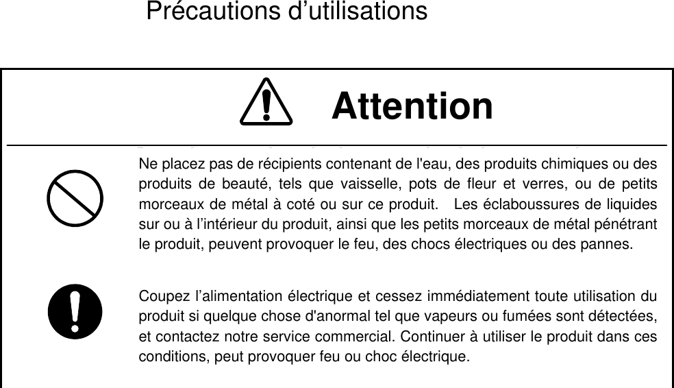
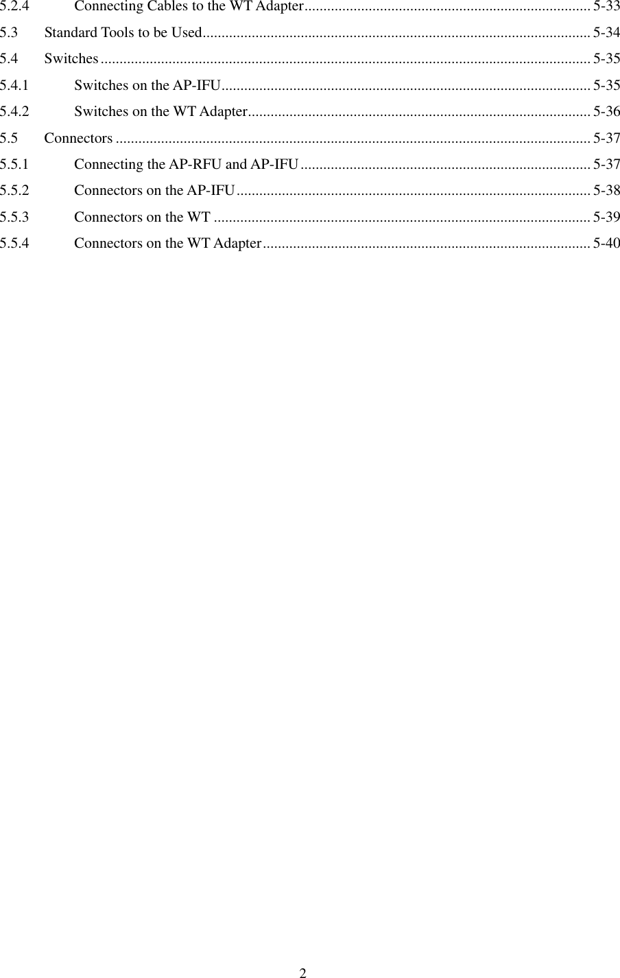
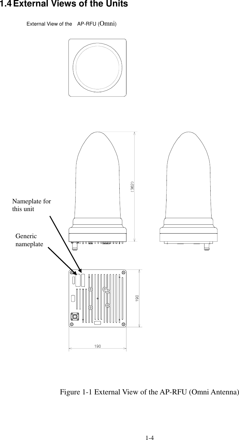
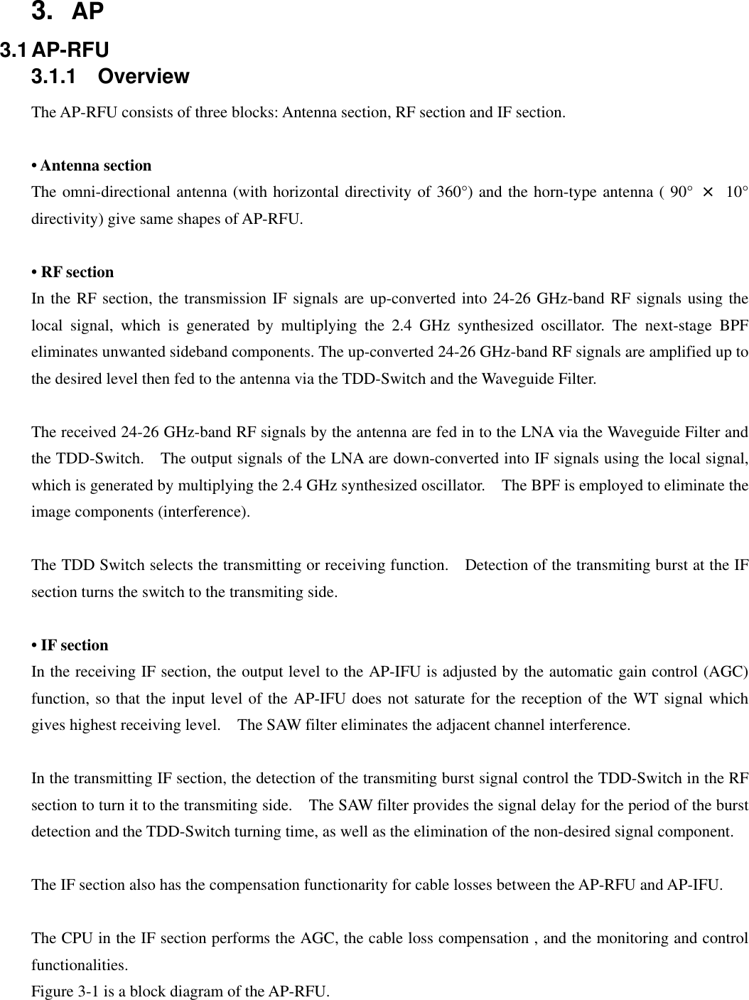
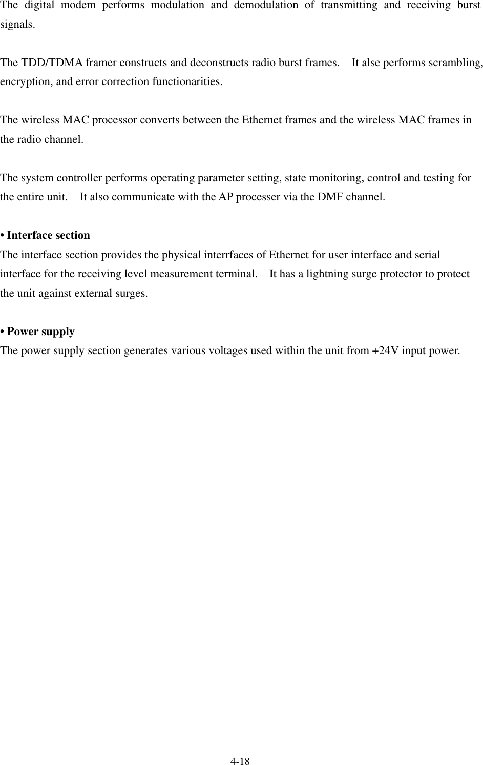
![3-13 Figure 3-1 AP-RFU Block Diagram 3.1.2 Operations and Indications The AP-RFU does not have any operation or indication panels. 3.2 AP-IFU 3.2.1 Overview AP-IFU consists of three blocks: IF section, digital section and interface section. • IF section The transmission IF section performs quadrature modulation of 427.5MHz IF frequency according to the transmission output from the digital modem installed in the WT-ASIC. In the receiving IF section, the received burst signal level is adjusted by the automatic gain control (AGC) function of the digital modem. The quadrature demodulator downconverts the received IF signal into the baseband signal. The digital section consists of a digital modem, TDD/TDMA framer, wireless MAC processor, and system controller. These functionarities are equipped in the WT-ASIC. The digital modem performs modulation and demodulation of transmitting and receiving burst signals. The interface section has an interface between the AP and the upper unit (100BASE-TX). It provides a 100BASE-FX interface by installing the AP optical INTF unit. to IFUAP-RFUWGBPFRFSWLNASW2.4GHzSynth26G:×10×n×2DOWN_CONVTRSEL(RF)PA×2UP_CONVFREQ_CNTIF部HYBASKMODEMTempCNT D/AD/AAGC×2HYB1282.5MHzATPCAGC213.75MHzMAX_HOLD/AVERAGING A/DTRCNTVariable[20dB]TempCNTRFU│IFUContTemp SensVAR_ATT[30dB]CABLELOSSDC+16VLOGAMPTMGGenCOMP THCNTObstacleinformationTRSEL(RF)FREQ_CNT[DATLCLK/LE]427.5MHzSAW BPFIF_Freq1710MHzSAW BPFHornAntenna(V/H)orOmniAntenna(V/H)×3BPFSAWBPFIRFDielectric_BPFLOGAMPSAW_BPFAGC2RX_LVLCNTAUTO ON/OFFAGC2RFU-IFAP-RFU_PSSerge protectionCoaxCABLE](https://usermanual.wiki/Japan-Radio/NTG335-EL0/User-Guide-580133-Page-25.png)
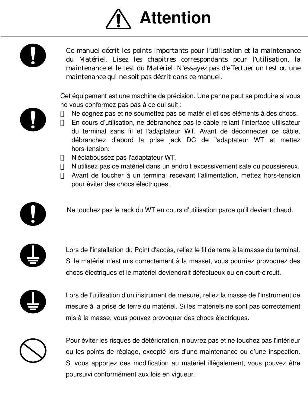
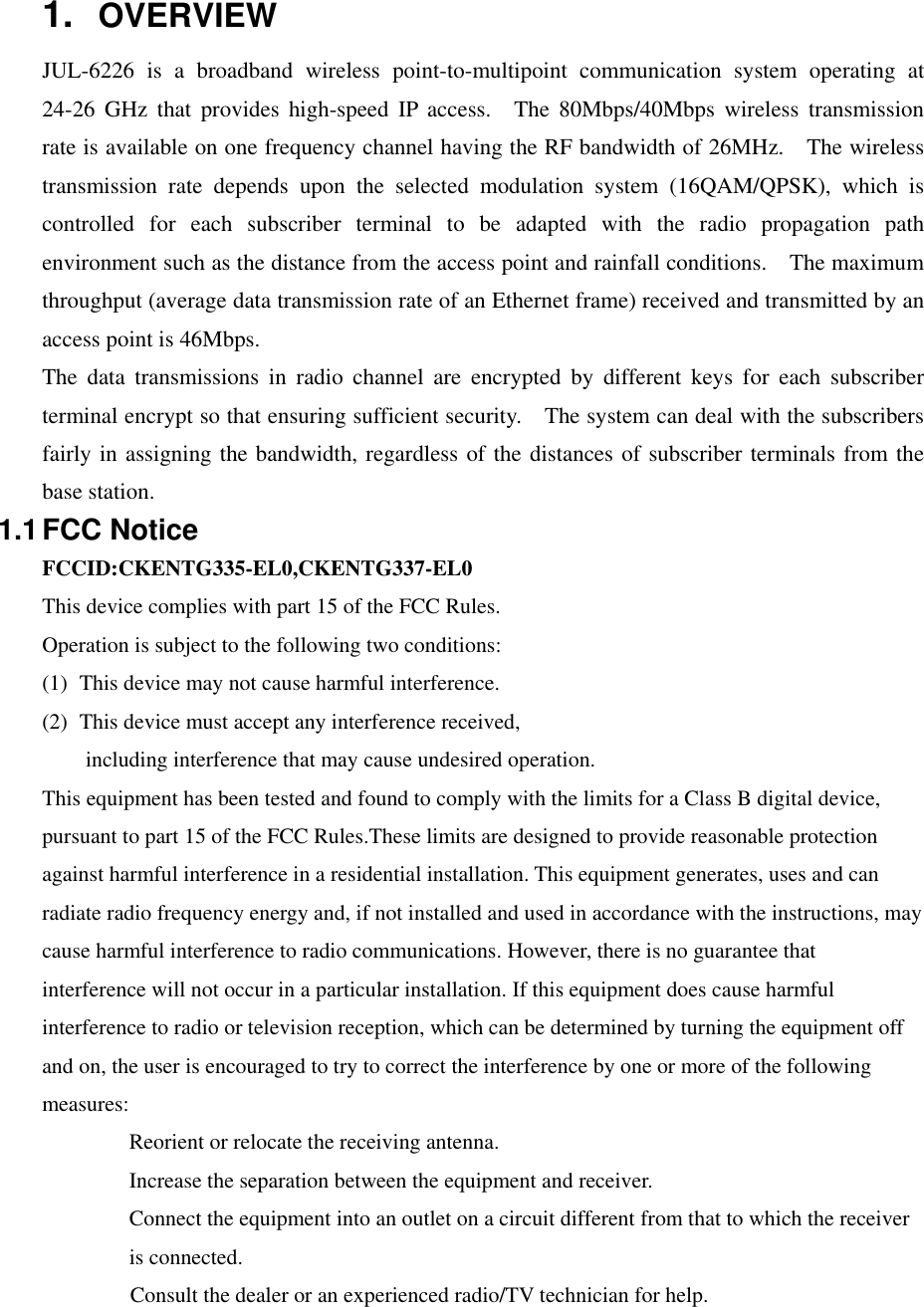
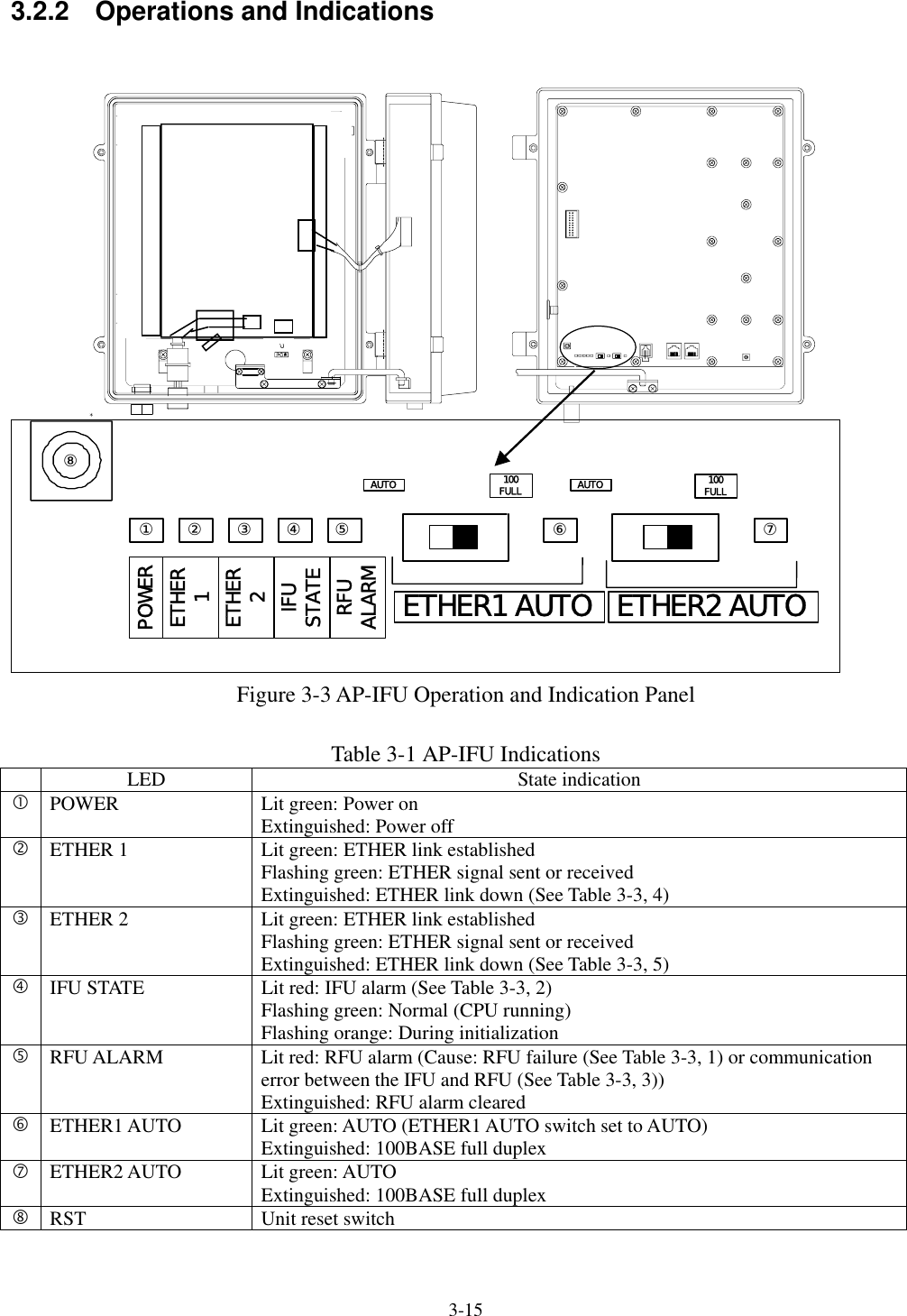
![3-14 The digital section consists of the wireless MAC processor, TDD/TDMA controller, modem and system controller. The wireless MAC processor converts between the Ethernet frames that the interface section handles and wireless MAC frames. It also schedules the dynamic slot assignment. The TDD/TDMA controller performs scrambling, encryption, error correction and other processing. The system controller performs operating parameter setting, state monitoring, control and testing for the modem, TDD/TDMA processor, wireless MAC processor and network interface. It also sends and receives maintenance signals via SNMP. It performs delay control, authentication and other procedures, operating parameter setting, state monitoring, control and testing for the subordinate WTs over a DMF channel. The transmission IF section in the IF section performs quadrature modulation for the transmission baseband signals at 427.5MHz LOC frequency for upconversion to IF signals. It also controls the output level to the desired level based on the control from the ASIC. The receive IF section equalizes the level of the reception waves arriving in a wide level range using the automatic gain control (AGC) from the ASIC, and then downconverts them into baseband signals. Figure 3-2 is a block diagram of the AP-IFU. Figure 3-2 AP-IFU Block Diagram AP-IFU+5VRegulat0/90HYB ×20/0BALUNBLC BPF213.75MHzLC_L +5LC BP+5LC_LdigitalATTUNB-3.3V+3.3_ +3.3_D+5V+16V+16Vto RFURegulatRegulat0/00/90ASKMODEMInterface partPHY_RST(FROM APL2SW_RST(FROM APTRANSLAYER2SWRJ-45RJ-45TRANSPHYTRANS TRANS25MHzRS-232Cdriver/reci4pinMOJURAMACTDDAP-DigitalU-CPU15.625ResetIC TMPSENS20MHzLVLCNT_T/R+16V(RFU)+3.3V(for AP/MODEM-ASIC,IF)+2.5V(for AP-ASIC)+1.8V(for U-CPU,D-CPU,L2SW)TT)+2.5V+3.3V+1.8V+3.3VMODDEMMODEMASICS-CPURTFROM64MserialEEPROSDRAM8M×D-CPUFROM16MSDRAM8M×FROM16MSDRAM8M×27.83MHzTXRXD-FIFOD-FIFOEDC2.5MS_RST[FROM_AP-ASIC]D_RST[FROM_AP-ASIC]U_RST[FROM_AP-ASIC]MODEM-ASIC RST+1.8V+5VRegulat+3.3_ASIC+1.5VTDD_SELECTIFU-MAC(to PC)DC-48VPowsupplyconn.Powersupply100BASETXPowsupplyconn.IF partSWMOD_I/Q(BAL)DEM_I/Q(UNBAL)toRFUSergeprotectionSergeprotectionSergeprotectionIFU-PSCoaxCABLE](https://usermanual.wiki/Japan-Radio/NTG335-EL0/User-Guide-580133-Page-26.png)
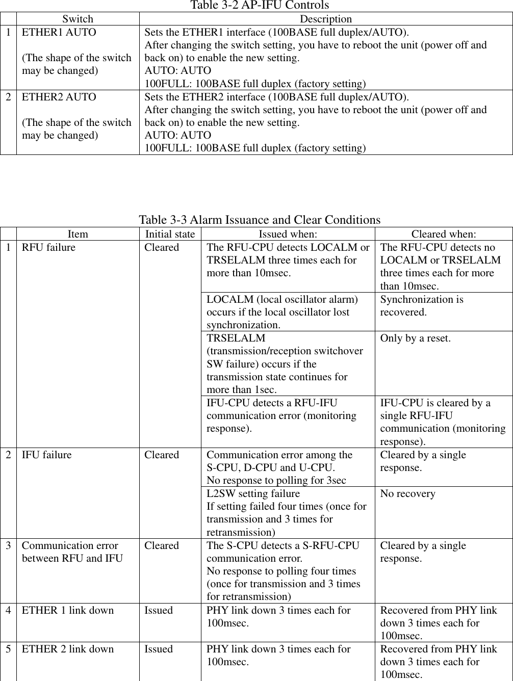
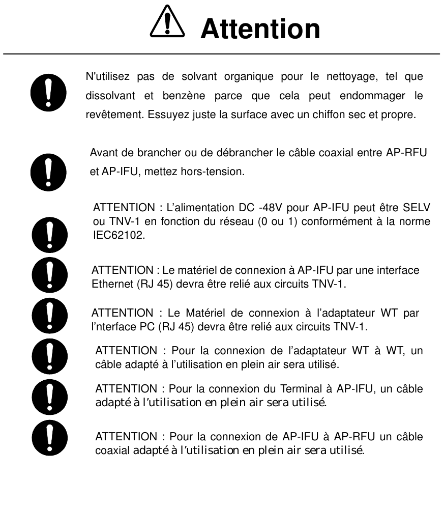
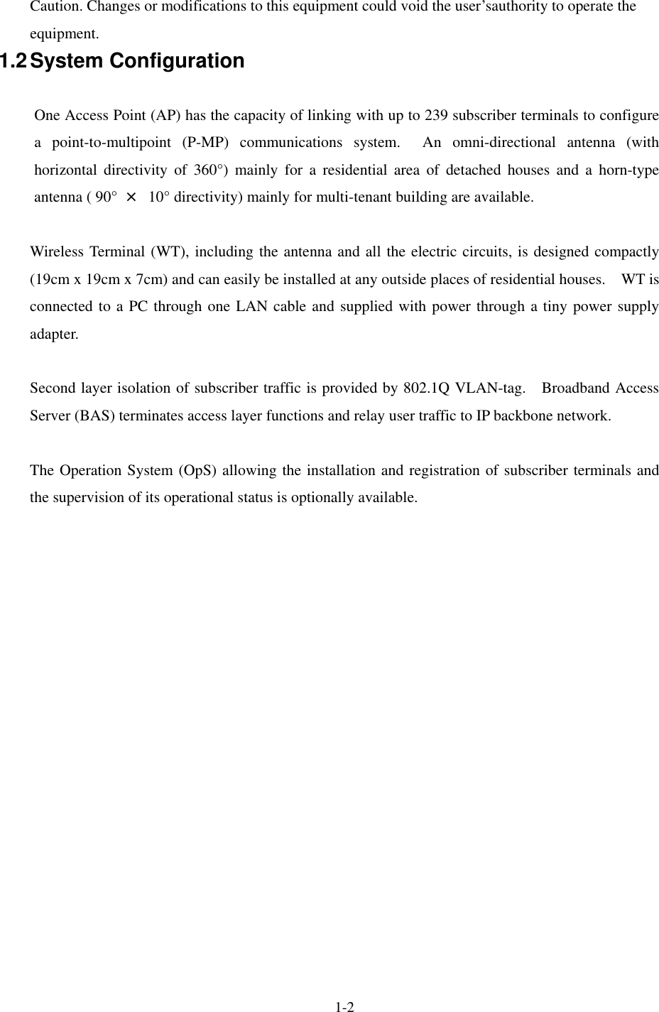
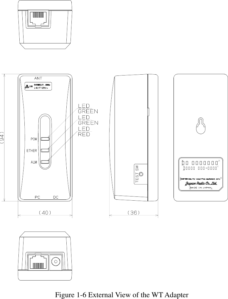
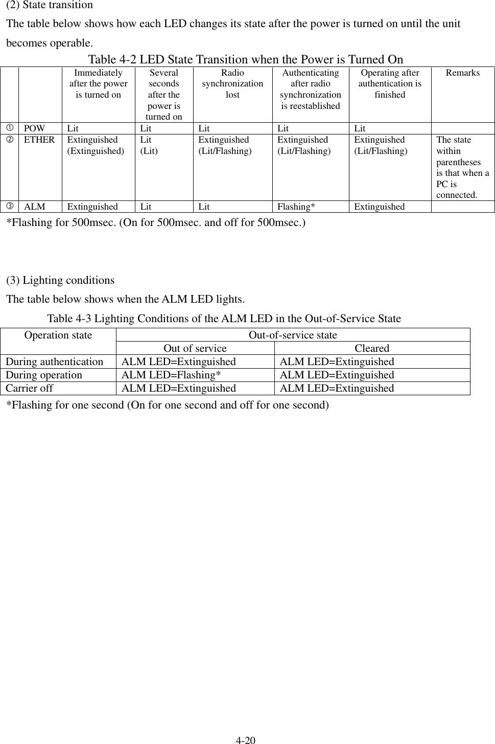
![4-19 Figure 4-1 is a block diagram of the WT. Figure 4-1 WT Block Diagram 4.1.2 Indications (1) Indications The indications on the WT adapter allows you to check the state of the WT. Table 4-1 Indications on the WT Adapter LED Indication cPOW Lit green: Power on Extinguished: Power off dETHER Lit green: ETHER link established Flashing green: Transmission or reception on the ETHER port Extinguished: ETHER link down eALM Lit red: Wireless synchronization lost Flashing red: Flashing red for 500msec: Wireless synchronization established (during authentication) Flashing red for 1 sec: VID use halted Extinguished: Wireless synchronization established (after authentication) Figure 4-2 Indications on the WT Adapter Interface partTransSerge protectionPHYRJ45RS-232DRV/REC4P_MJLED DRVMJMJMOD_I/Q(BAL)DEM_I/Q(UNB)Power supply part(digital)DC/DCCONV+3.3V_D(DIGITAL)+3.3V_A(ANALOG)+1.5V(for ASIC)AGC(Analog)TRSEL(RF)X'TALMAC TDDMODDEMCPUASICATPC(Analog)DC+24VAGC(Digital)ATPC(Digital)TRSEL(IF)to IF partD/AConvD/AConvPLL20MHz/80MHzSignal processing partFRASHROMTEMPSENSPONRST EEPROM SDRAMOFFSET_CNTFREQ_CNT(RF) AntennaWGBPFRFSWLNASW2.4GHzSynth26G:×10×n×2DOWN_CONVTRSEL(RF)PA×2UP_CONVFREQ_CNTto Signal processing part0/900/90HYB×20/0213.75MHzSW TRSEL(IF)DEM_I/QAGC(Analog)UNBBALSAW BPFDEM_ICAGC(Digital)0/0WT-IFMOD_ICATPC(Analog)MOD_I/Q×3 HYB427.5MHz 1282.5MHzIF_Freq1710MHzTRSEL(RF)FREQ_CNT[CLK/DAT/LE]BALUNBSAW BPFATPC(Digital)HYBDielectricBPFIRFIF_Freq1710MHzSAW BPFLC BPFWT-MACWT_PSWT](https://usermanual.wiki/Japan-Radio/NTG335-EL0/User-Guide-580133-Page-31.png)
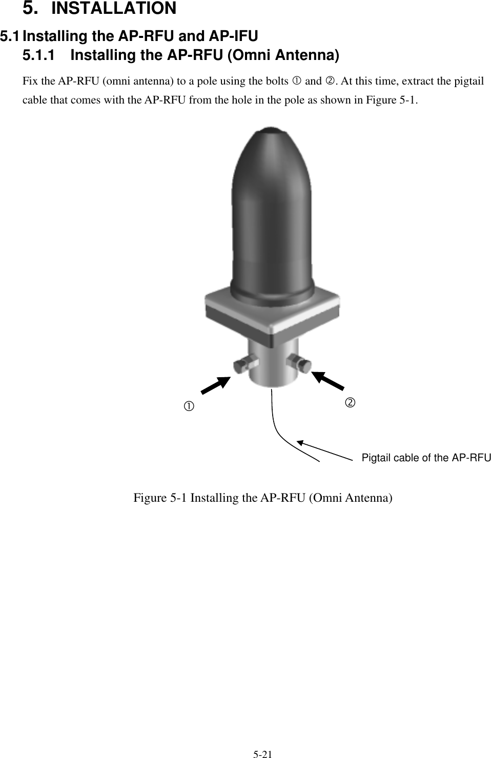
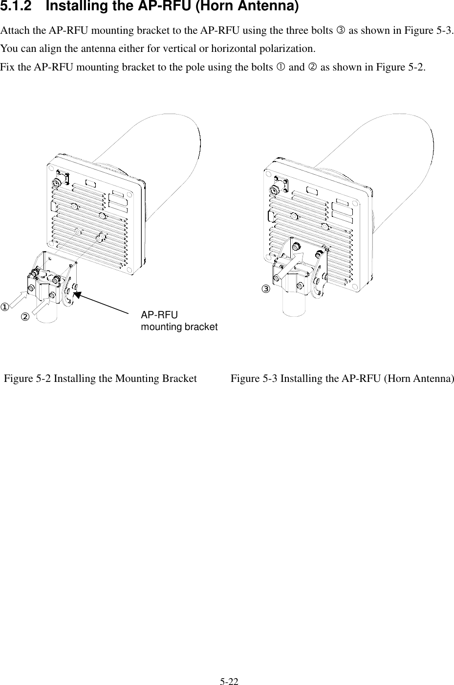
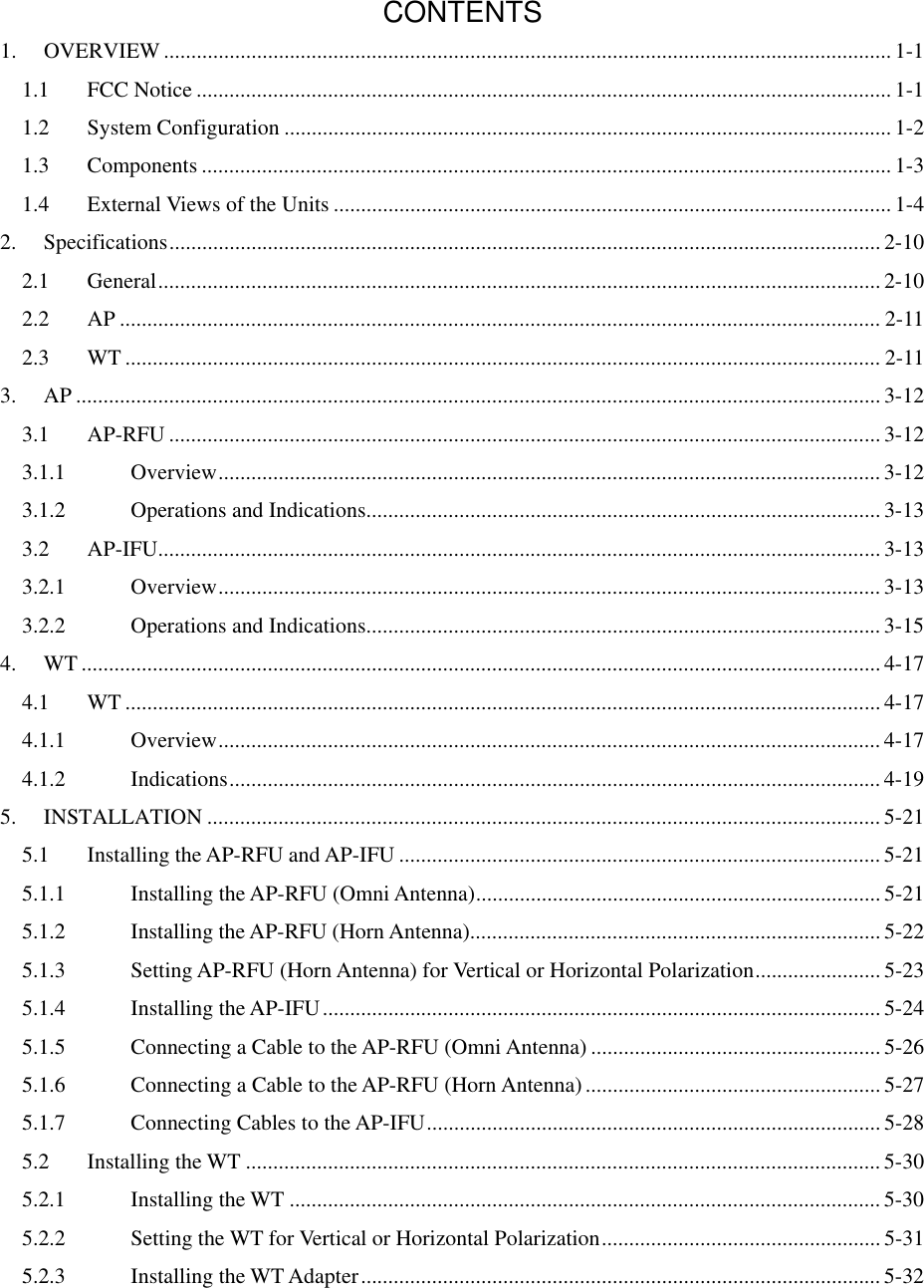
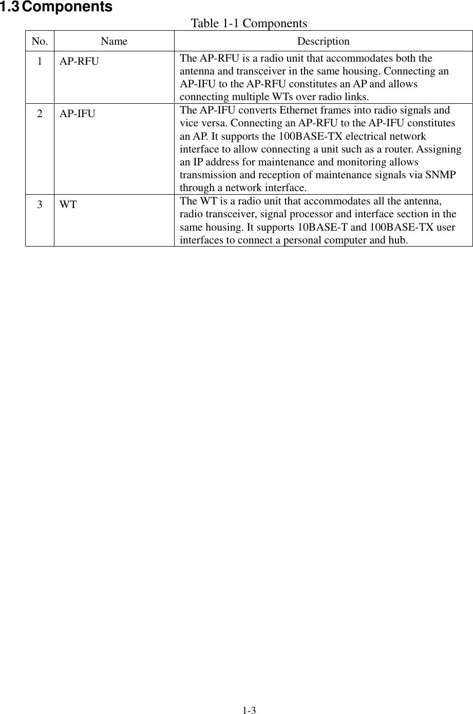
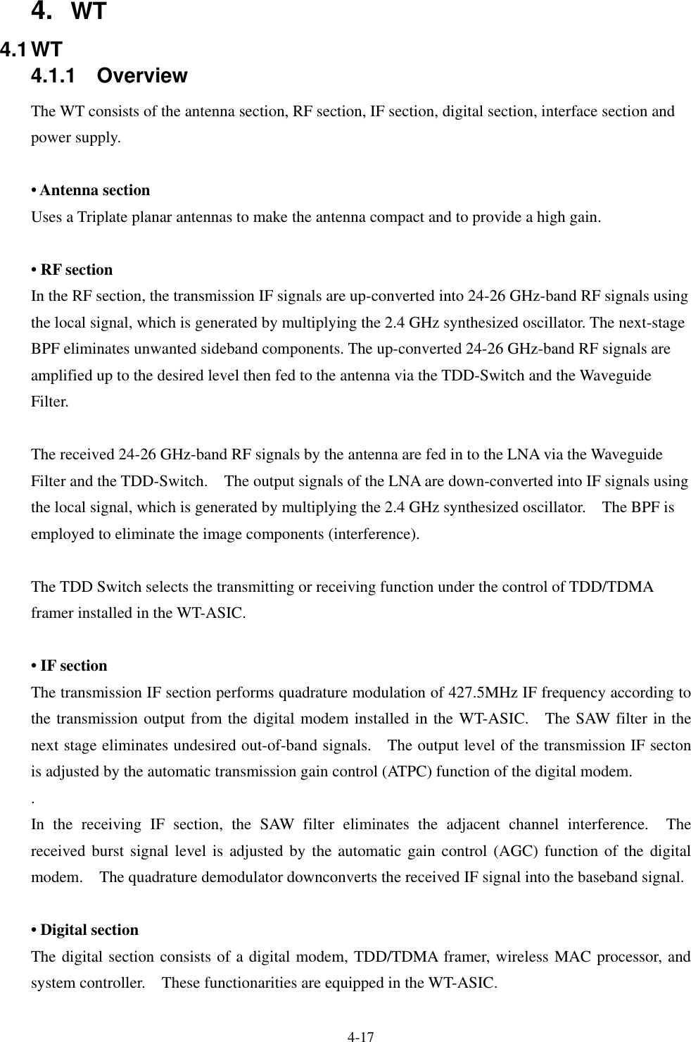
![5-34 5.3 Standard Tools to be Used The table below lists the tools used during installation or maintenance of the units. Table 5-1 Tools Used No. Unit name Used for: Tightening torque [N•cm] Tool 1 Door M5 265 Torx driver (VESSEL T25H-120) 2 Power board M4 127 Phillips screwdriver 3 Cable clamp M4 127 Phillips screwdriver 4 Power board M4 127 Phillips screwdriver 5 Cable clamp M4 127 Phillips screwdriver 6 Ground M4 nut 127 Socket driver (Width across flats: 7) 7 SC lock M16 nut 80 to 120 Spanner wrench (Width across flats: 22)8 MC mounting plate M3 57 Tightened manually 9 Mounting plate M8 1080 Socket wrench (Width across flats: 13) 10 MC mounting feet M3 57 Socket driver (Width across flats: 5.5) 11 AP- IFU MC mounting feet (for cascade connection) M4 130 Phillips screwdriver 12 Small window M4 127 Torx driver (VESSEL T20H-120) 13 Mounting bracket M5 265 Allen wrench (Width across flats: 5) 14 WT Ethernet cable Crimping tool for RJ-45 (Release-after-crimp type) 15 AP-RFU (Omni) Mounting bracket (axis tightening) M16 9410 Socket wrench (Width across flats: 24) 16 AP-RFU (Horn) Mounting bracket M5 265 Allen wrench (Width across flats: 5) The appropriate tightening torque is ±10% of the value indicated in the table.](https://usermanual.wiki/Japan-Radio/NTG335-EL0/User-Guide-580133-Page-46.png)