Japan Radio NTG335-EL0 Access Point User Manual Installation Manual
Japan Radio Co Ltd. Access Point Installation Manual
Installation Manual

JUL-6226 MANUAL
APRIL.13, 2005
Version 1.4
1
Introduction
• Read this instruction manual carefully before use. Be sure you fully understand the instructions
in this manual before using the equipment.
• After reading, save this instruction manual and refer to it as necessary. If you have any
questions about or there is something wrong with the equipment, refer to this manual.
1
Before use:
Warning Indications
This manual and the product use some icons to help you use the product properly and
prevent any damage to you and other people or property. The following icons classify
the potential damage if the indications are ignored or the product is used improperly.
When reading the manual, keep these in mind.
Wrong handling of this product may cause
serious personal injury or death.
Wrong handling of this product may cause
personal injury or damage to properties.
Warning
Caution
Examples of icons
icons indicate prohibition. A detailed prohibition description
is given in the vicinity of the icon. (The figure on the left
prohibits disassembly.)
Warning labels
Do not remove, damage or alter the warning labels.
Dangerous
voltages
General
prohibitions
Do not
disassemble.
General
advice
Unplug
A triangle is an alert to call your attention including a warning or
danger indication. The graphics within the triangle differs
depending on the caution. (The figure on the left shows a caution
for electrical shocks.)
● icons require you to perform the item. A detailed instruction
description is given in the vicinity of the icon. (The figure on the
left instruct to unplug the equipment.)

Precautions in Use
Don’t place containers having water, chemicals or cosmetics,
such as vessels, flower pots and glasses, or small pieces of
metals near or on top of this product. Liquids spilled over or into
or small metal pieces getting into the product may cause fire,
electrical shocks or failures.
Turn off the power and stop using the unit immediately if
something abnormal such as fumes or smoke is detected, and
contact our sales department, branch or sales office. Continuing
to use the product as is may cause fire or electrical shock.
Warning
This manual describes important points to operate and maintain the
equipment. Read the related sections when operating, maintaining
and testing the unit. Do not try to carry out a test or maintenance not
covered in this manual.
This equipment is a precision machine. A failure may occur if you do
not observe the following:
• Do not jar or subject this equipment and the units to shocks.
• During operation, do not unplug the cable connected between the
wireless terminal’s user interface (26G-WIPAS2-WT-E) and the WT
adapter. Before unplugging this cable, first unplug the DC jack from
the WT adapter and turn the power off.
• Do not splash water on the WT adapter.
• Do not use this equipment in a place with excessive dirt or dust.
Before touching a power-receiving terminal, turn the input power off to
avoid electrical shocks.
When installing the Access Point (AP), connect the ground wire to the
ground terminal. If the equipment is not grounded properly, you may
get electrical shocks when the equipment becomes faulty or shorted.
When using a measuring instrument, connect the ground terminal of
the measuring instrument to the ground terminal of this equipment. If
the equipment is not grounded properly, you may get electrical
shocks.
To avoid shock hazards, do not open and touch the inside or
adjustment points except for maintenance or inspection. If you modify
the equipment illegally, you may be punished according to the Radio
Law.
Cautions
Do not touch the rack of the wireless terminal’s user interface (26G-
WIPAS2-WT-E) duirng operation because it becomes hot.
Do not touch the rack of the WT duiring operation because it becames hot.
・During operation, do not unplug the cable connected between the WT and
WT adapter.Before unplugging this cable, first unplug the DC jack from the
WT adapter and trun the power off.
Don't use organic solvent for cleaning such as thinner and benzene because
this may damage the coating. Just wipe the surface with a clean dry cloth.
If you have any questions about this equipment or if you want to make
inquires about failures, please contact our sales department.
Cautions
Before plugging in or unplugging the coaxial cable between the 26G-
WIPAS2-AP-RFU and 26G-WIPAS2-AP-IFU, turn the power off.
For the address of our sales department, see the end of this manual.
Do not look directly at the SC connector of the media converter
installed in this equipment or the end of the optical fiber connecting to
the SC connector. This may harm your eyes because they use a
powerful light source.
Befour plugging in or unplugging the coaxial cable between the AP-RFU and
AP-IFU, turn the power off.
Befour plugging in or unplugging the coaxial cable between the AP-RFU and
AP-IFU, turn the power off.
CAUTION: The DC -48V power supply voltage for AP-IFU shall be SELV or TNV-1
depending on the network environment (0 or 1) acc. to IEC62102.
CAUTION: The Equipment for connection to AP-IFU Ethernet-interface(RJ-45)
shall be appropriate to connect to TNV-1 circuits.
CAUTION: The Equipment for connection to WT adapter PC-interface(RJ-45) shall
be appropriate to connect to TNV-1 circuits.
CAUTION: For the connection AP-IFU to AP-RFU and a coaxial cable suitable for
outdoor use shall be installed.
CAUTION: For the connection Terminal Equipment to AP-IFU and a cables suitable
for outdoor use shall be installed.
CAUTION: For the connection WT adapter to WT and a cable suitable for outdoor
use shall be installed.
Avant usage:
Indications Préventives
This manual and the product use some icons to help you use the product properly and
prevent any damage to you and other people or property. The following icons classify
the potential damage if the indications are ignored or the product is used improperly.
When reading the manual, keep these in mind.
Wrong handling of this product may cause
serious personal injury or death.
Wrong handling of this product may cause
personal injury or damage to properties.
Warning
Caution
Exemples d'icônes
Attention
N'enlevez jamais, n’endommagez jamais et ne changez jamais les signalisation de
danger.
Dangerous
voltages
General
prohibitions
Do not
disassemble.
General
advice
Unplug
Un triangle est une alerte pour attirer votre attention en cas de
danger ou de conseil de prudence. Le signe à l’interieur du triangle
diffère selon le risque. (L’exemple de gauche signale un risque
électrique.)
Ce type d’icône exige que vous exécutiez l'action Une description
plus détaillée est donnée près de l'icône (la plus à gauche exige de
debrancher le matériel avant toute opération.)
Le manuel d’utilisation et le produit utilisent des icônes pour vous aider à utiliser correctement le
produit et prévenir tout dommages sur vous, sur des tiers ou sur des biens. Les icônes qui suivent,
indiquent le niveau des dommages éventuels si les précautions indiquées sont ignorées ou si le
produit est mal utilisé. Quand vous lirez le manuel d’utilisation, faites attention à ces indications.
Une mauvaise utilisation de ce produit peut causer de
sérieux dommages corporels ou la mort.
Une mauvaise utilisation de ce produit peut causer des
dommages corporels ou endommager des biens.
Danger
Prudence
Danger
électrique
Interdiction
g
énérale
Ne pas
démonte
r
Conseil
g
énéral
Débranchez
Les deux icônes de gauche indiquent une interdiction. Une
description plus détaillée est donnée près de l'icone (la plus à
gauche interdit le démontage.)
Précautions d’utilisations
Don’t place containers having water, chemicals or cosmetics,
such as vessels, flower pots and glasses, or small pieces of
metals near or on top of this product. Liquids spilled over or into
or small metal pieces getting into the product may cause fire,
electrical shocks or failures.
Turn off the power and stop using the unit immediately if
something abnormal such as fumes or smoke is detected, and
contact our sales department, branch or sales office. Continuing
to use the product as is may cause fire or electrical shock.
Warning
Attention
Ne placez pas de récipients contenant de l'eau, des produits chimiques ou des
produits de beauté, tels que vaisselle, pots de fleur et verres, ou de petits
morceaux de métal à coté ou sur ce produit. Les éclaboussures de liquides
sur ou à l’intérieur du produit, ainsi que les petits morceaux de métal pénétrant
le produit, peuvent provoquer le feu, des chocs électriques ou des pannes.
Coupez l’alimentation électrique et cessez immédiatement toute utilisation du
produit si quelque chose d'anormal tel que vapeurs ou fumées sont détectées,
et contactez notre service commercial. Continuer à utiliser le produit dans ces
conditions, peut provoquer feu ou choc électrique.
This manual describes important points to operate and maintain the
equipment. Read the related sections when operating, maintaining
and testing the unit. Do not try to carry out a test or maintenance not
covered in this manual.
This equipment is a precision machine. A failure may occur if you do
not observe the following:
• Do not jar or subject this equipment and the units to shocks.
• During operation, do not unplug the cable connected between the
wireless terminal’s user interface (26G-WIPAS2-WT-E) and the WT
adapter. Before unplugging this cable, first unplug the DC jack from
the WT adapter and turn the power off.
• Do not splash water on the WT adapter.
• Do not use this equipment in a place with excessive dirt or dust.
Before touching a power-receiving terminal, turn the input power off to
avoid electrical shocks.
When installing the Access Point (AP), connect the ground wire to the
ground terminal. If the equipment is not grounded properly, you may
get electrical shocks when the equipment becomes faulty or shorted.
When using a measuring instrument, connect the ground terminal of
the measuring instrument to the ground terminal of this equipment. If
the equipment is not grounded properly, you may get electrical
shocks.
To avoid shock hazards, do not open and touch the inside or
adjustment points except for maintenance or inspection. If you modify
the equipment illegally, you may be punished according to the Radio
Law.
Cautions
Do not touch the rack of the wireless terminal’s user interface (26G-
WIPAS2-WT-E) duirng operation because it becomes hot.
Ne touchez pas le casier de la WT duiring opération parce qu'il becames
chaud.
・During operation, do not unplug the cable connected between the WT and
WT adapter.Before unplugging this cable, first unplug the DC jack from the
WT adapter and trun the power off.
Attention
Ce manuel décrit les points importants pour l’utilisation et la maintenance
du Matériel. Lisez les chapitres correspondants pour l’utilisation, la
maintenance et le test du Matériel. N'essayez pas d'effectuer un test ou une
maintenance qui ne soit pas décrit dans ce manuel.
Cet équipement est une machine de précision. Une panne peut se produire si vous
ne vous conformez pas pas à ce qui suit :
・ Ne cognez pas et ne soumettez pas ce matériel et ses éléments à des chocs.
・ En cours d’utilisation, ne débranchez pas le câble reliant l’interface utilisateur
du terminal sans fil et l'adaptateur WT. Avant de déconnecter ce câble,
débranchez d’abord la prise jack DC de l'adaptateur WT et mettez
hors-tension.
・ N'éclaboussez pas l'adaptateur WT.
・ N'utilisez pas ce matériel dans un endroit excessivement sale ou poussiéreux.
・ Avant de toucher à un terminal recevant l’alimentation, mettez hors-tension
pour éviter des chocs électriques.
Lors de l’installation du Point d'accès, reliez le fil de terre à la masse du terminal.
Si le matériel n'est mis correctement à la masset, vous pourriez provoquez des
chocs électriques et le matériel deviendrait défectueux ou en court-circuit.
Lors de l’utilisation d’un instrument de mesure, reliez la masse de l'instrument de
mesure à la prise de terre du matériel. Si les matériels ne sont pas correctement
mis à la masse, vous pouvez provoquer des chocs électriques.
Pour éviter les risques de détérioration, n'ouvrez pas et ne touchez pas l'intérieur
ou les points de réglage, excepté lors d'une maintenance ou d’une inspection.
Si vous apportez des modification au matériel illégalement, vous pouvez être
poursuivi conformément aux lois en vigueur.
Ne touchez pas le rack du WT en cours d’utilisation parce qu'il devient chaud.
Don't use organic solvent for cleaning such as thinner and benzene because
this may damage the coating. Just wipe the surface with a clean dry cloth.
If you have any questions about this equipment or if you want to make
inquires about failures, please contact our sales department.
Cautions
Before plugging in or unplugging the coaxial cable between the 26G-
WIPAS2-AP-RFU and 26G-WIPAS2-AP-IFU, turn the power off.
For the address of our sales department, see the end of this manual.
Do not look directly at the SC connector of the media converter
installed in this equipment or the end of the optical fiber connecting to
the SC connector. This may harm your eyes because they use a
powerful light source.
Befour plugging in or unplugging the coaxial cable between the
AP-RFU and AP-IFU, turn the power off.
Befour qui branche ou unplugging le câble coaxial entre l'AP-RFU et
AP-IFU, tournez l'hors-tension.
CAUTION: The DC -48V power supply voltage for AP-IFU shall be SELV or TNV-1
depending on the network environment (0 or 1) acc. to IEC62102.
CAUTION: The Equipment for connection to AP-IFU Ethernet-interface(RJ-45)
shall be appropriate to connect to TNV-1 circuits.
CAUTION: The Equipment for connection to WT adapter PC-interface(RJ-45) shall
be appropriate to connect to TNV-1 circuits.
CAUTION: For the connection AP-IFU to AP-RFU and a coaxial cable suitable for
outdoor use shall be installed.
CAUTION: For the connection Terminal Equipment to AP-IFU and a cables suitable
for outdoor use shall be installed.
CAUTION: For the connection WT adapter to WT and a cable suitable for outdoor
use shall be installed.
Attention
N'utilisez pas de solvant organique pour le nettoyage, tel que
dissolvant et benzène parce que cela peut endommager le
revêtement. Essuyez juste la surface avec un chiffon sec et propre.
ATTENTION : L’alimentation DC -48V pour AP-IFU peut être SELV
ou TNV-1 en fonction du réseau (0 ou 1) conformément à la norme
IEC62102.
ATTENTION : Le matériel de connexion à AP-IFU par une interface
Ethernet (RJ 45) devra être relié aux circuits TNV-1.
ATTENTION : Le Matériel de connexion à l’adaptateur WT par
l’nterface PC (RJ 45) devra être relié aux circuits TNV-1.
ATTENTION : Pour la connexion de l’adaptateur WT à WT, un
câble adapté à l’utilisation en plein air sera utilisé.
ATTENTION : Pour la connexion du Terminal à AP-IFU, un câble
adapté à l’utilisation en plein air sera utilisé.
ATTENTION : Pour la connexion de AP-IFU à AP-RFU un câble
coaxial adapté à l’utilisation en plein air sera utilisé.
Avant de brancher ou de débrancher le câble coaxial entre AP-RFU
et AP-IFU, mettez hors-tension.
CONTENTS
1. OVERVIEW ..................................................................................................................................... 1-1
1.1 FCC Notice ............................................................................................................................... 1-1
1.2 System Configuration ............................................................................................................... 1-2
1.3 Components .............................................................................................................................. 1-3
1.4 External Views of the Units ...................................................................................................... 1-4
2. Specifications.................................................................................................................................. 2-10
2.1 General.................................................................................................................................... 2-10
2.2 AP ........................................................................................................................................... 2-11
2.3 WT .......................................................................................................................................... 2-11
3. AP ................................................................................................................................................... 3-12
3.1 AP-RFU .................................................................................................................................. 3-12
3.1.1 Overview......................................................................................................................... 3-12
3.1.2 Operations and Indications.............................................................................................. 3-13
3.2 AP-IFU.................................................................................................................................... 3-13
3.2.1 Overview......................................................................................................................... 3-13
3.2.2 Operations and Indications.............................................................................................. 3-15
4. WT .................................................................................................................................................. 4-17
4.1 WT .......................................................................................................................................... 4-17
4.1.1 Overview......................................................................................................................... 4-17
4.1.2 Indications....................................................................................................................... 4-19
5. INSTALLATION ........................................................................................................................... 5-21
5.1 Installing the AP-RFU and AP-IFU ........................................................................................ 5-21
5.1.1 Installing the AP-RFU (Omni Antenna).......................................................................... 5-21
5.1.2 Installing the AP-RFU (Horn Antenna)........................................................................... 5-22
5.1.3 Setting AP-RFU (Horn Antenna) for Vertical or Horizontal Polarization....................... 5-23
5.1.4 Installing the AP-IFU...................................................................................................... 5-24
5.1.5 Connecting a Cable to the AP-RFU (Omni Antenna) ..................................................... 5-26
5.1.6 Connecting a Cable to the AP-RFU (Horn Antenna) ...................................................... 5-27
5.1.7 Connecting Cables to the AP-IFU................................................................................... 5-28
5.2 Installing the WT .................................................................................................................... 5-30
5.2.1 Installing the WT ............................................................................................................5-30
5.2.2 Setting the WT for Vertical or Horizontal Polarization................................................... 5-31
5.2.3 Installing the WT Adapter............................................................................................... 5-32
2
5.2.4 Connecting Cables to the WT Adapter............................................................................ 5-33
5.3 Standard Tools to be Used.......................................................................................................5-34
5.4 Switches.................................................................................................................................. 5-35
5.4.1 Switches on the AP-IFU.................................................................................................. 5-35
5.4.2 Switches on the WT Adapter........................................................................................... 5-36
5.5 Connectors .............................................................................................................................. 5-37
5.5.1 Connecting the AP-RFU and AP-IFU.............................................................................5-37
5.5.2 Connectors on the AP-IFU.............................................................................................. 5-38
5.5.3 Connectors on the WT .................................................................................................... 5-39
5.5.4 Connectors on the WT Adapter....................................................................................... 5-40
1. OVERVIEW
JUL-6226 is a broadband wireless point-to-multipoint communication system operating at
24-26 GHz that provides high-speed IP access. The 80Mbps/40Mbps wireless transmission
rate is available on one frequency channel having the RF bandwidth of 26MHz. The wireless
transmission rate depends upon the selected modulation system (16QAM/QPSK), which is
controlled for each subscriber terminal to be adapted with the radio propagation path
environment such as the distance from the access point and rainfall conditions. The maximum
throughput (average data transmission rate of an Ethernet frame) received and transmitted by an
access point is 46Mbps.
The data transmissions in radio channel are encrypted by different keys for each subscriber
terminal encrypt so that ensuring sufficient security. The system can deal with the subscribers
fairly in assigning the bandwidth, regardless of the distances of subscriber terminals from the
base station.
1.1 FCC Notice
FCCID:CKENTG335-EL0,CKENTG337-EL0
This device complies with part 15 of the FCC Rules.
Operation is subject to the following two conditions:
(1) This device may not cause harmful interference.
(2) This device must accept any interference received,
including interference that may cause undesired operation.
This equipment has been tested and found to comply with the limits for a Class B digital device,
pursuant to part 15 of the FCC Rules.These limits are designed to provide reasonable protection
against harmful interference in a residential installation. This equipment generates, uses and can
radiate radio frequency energy and, if not installed and used in accordance with the instructions, may
cause harmful interference to radio communications. However, there is no guarantee that
interference will not occur in a particular installation. If this equipment does cause harmful
interference to radio or television reception, which can be determined by turning the equipment off
and on, the user is encouraged to try to correct the interference by one or more of the following
measures:
Reorient or relocate the receiving antenna.
Increase the separation between the equipment and receiver.
Connect the equipment into an outlet on a circuit different from that to which the receiver
is connected.
Consult the dealer or an experienced radio/TV technician for help.
1-2
Caution. Changes or modifications to this equipment could void the user’sauthority to operate the
equipment.
1.2 System Configuration
One Access Point (AP) has the capacity of linking with up to 239 subscriber terminals to configure
a point-to-multipoint (P-MP) communications system. An omni-directional antenna (with
horizontal directivity of 360°) mainly for a residential area of detached houses and a horn-type
antenna ( 90° × 10° directivity) mainly for multi-tenant building are available.
Wireless Terminal (WT), including the antenna and all the electric circuits, is designed compactly
(19cm x 19cm x 7cm) and can easily be installed at any outside places of residential houses. WT is
connected to a PC through one LAN cable and supplied with power through a tiny power supply
adapter.
Second layer isolation of subscriber traffic is provided by 802.1Q VLAN-tag. Broadband Access
Server (BAS) terminates access layer functions and relay user traffic to IP backbone network.
The Operation System (OpS) allowing the installation and registration of subscriber terminals and
the supervision of its operational status is optionally available.

1-3
1.3 Components Table 1-1 Components
No. Name Description
1 AP-RFU The AP-RFU is a radio unit that accommodates both the
antenna and transceiver in the same housing. Connecting an
AP-IFU to the AP-RFU constitutes an AP and allows
connecting multiple WTs over radio links.
2 AP-IFU The AP-IFU converts Ethernet frames into radio signals and
vice versa. Connecting an AP-RFU to the AP-IFU constitutes
an AP. It supports the 100BASE-TX electrical network
interface to allow connecting a unit such as a router. Assigning
an IP address for maintenance and monitoring allows
transmission and reception of maintenance signals via SNMP
through a network interface.
3 WT The WT is a radio unit that accommodates all the antenna,
radio transceiver, signal processor and interface section in the
same housing. It supports 10BASE-T and 100BASE-TX user
interfaces to connect a personal computer and hub.
1-4
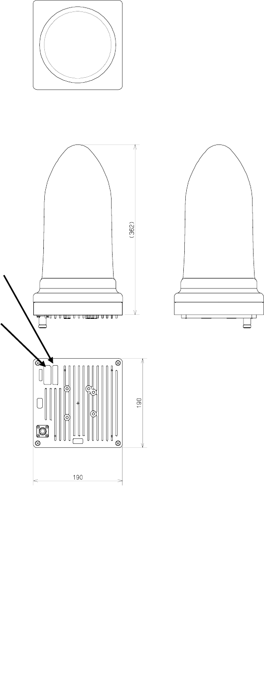
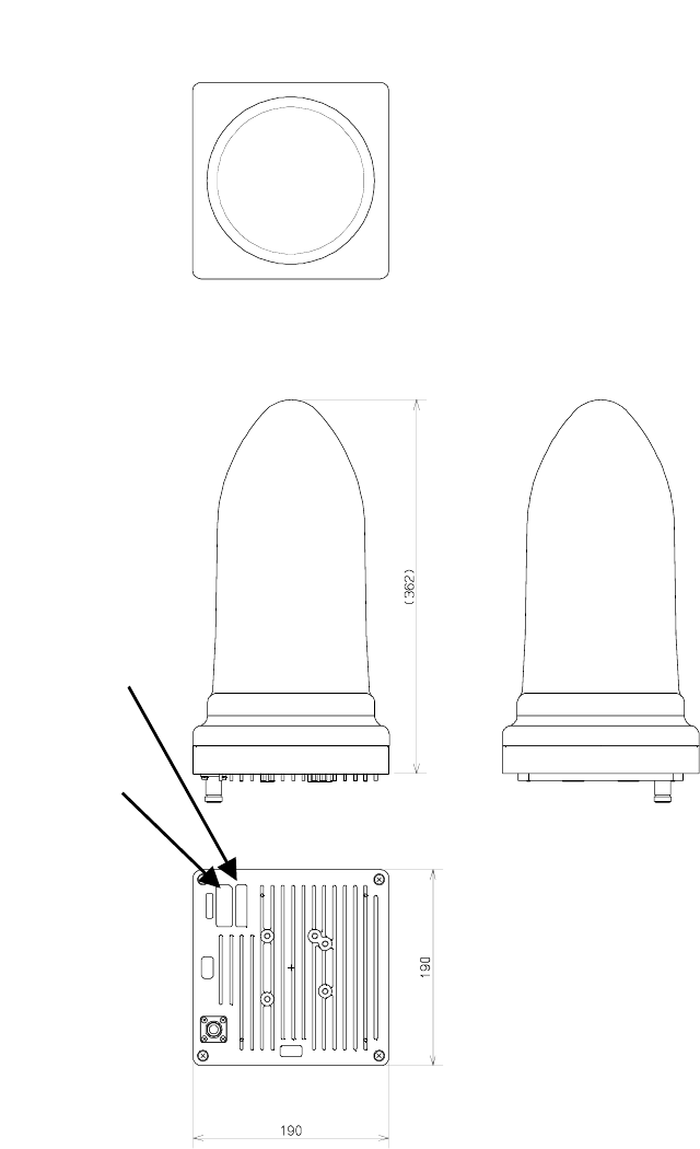
1.4 External Views of the Units
Figure 1-1 External View of the AP-RFU (Omni Antenna)
External View of the AP-RFU (Omni)
Nameplate for
this unit
Generic
nameplate
1-5
Figure 1-2 External View of the AP-RFU (Horn Antenna)
External View of the AP-RFU (Omni)
N
ameplate
for this unit
Generic
name
p
lat
External View of the AP-RFU (Horn)
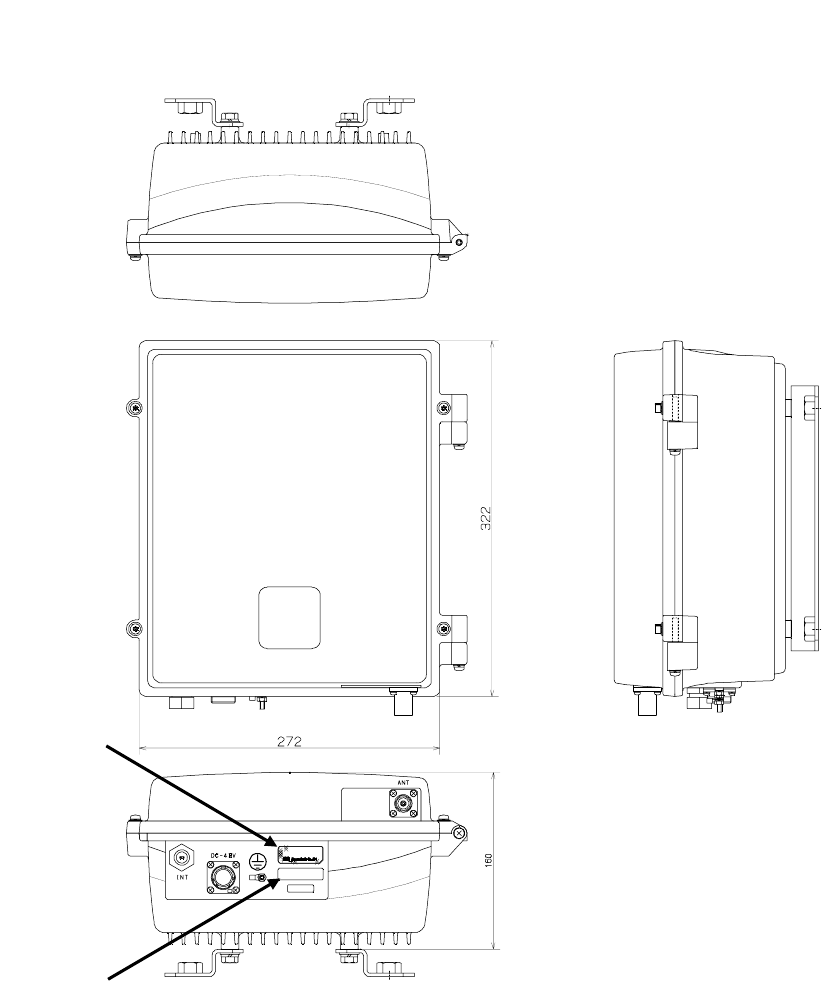
Figure 1-3 External View of the AP-IFU
External View of the AP-IFU
SER. NO .
INPU T :
DATE :
MAD E IN JAP AN
TYPE W−A P< EL0 >
DC−4 8V 0.8A
Generic
nameplate
Nameplate for
this unit
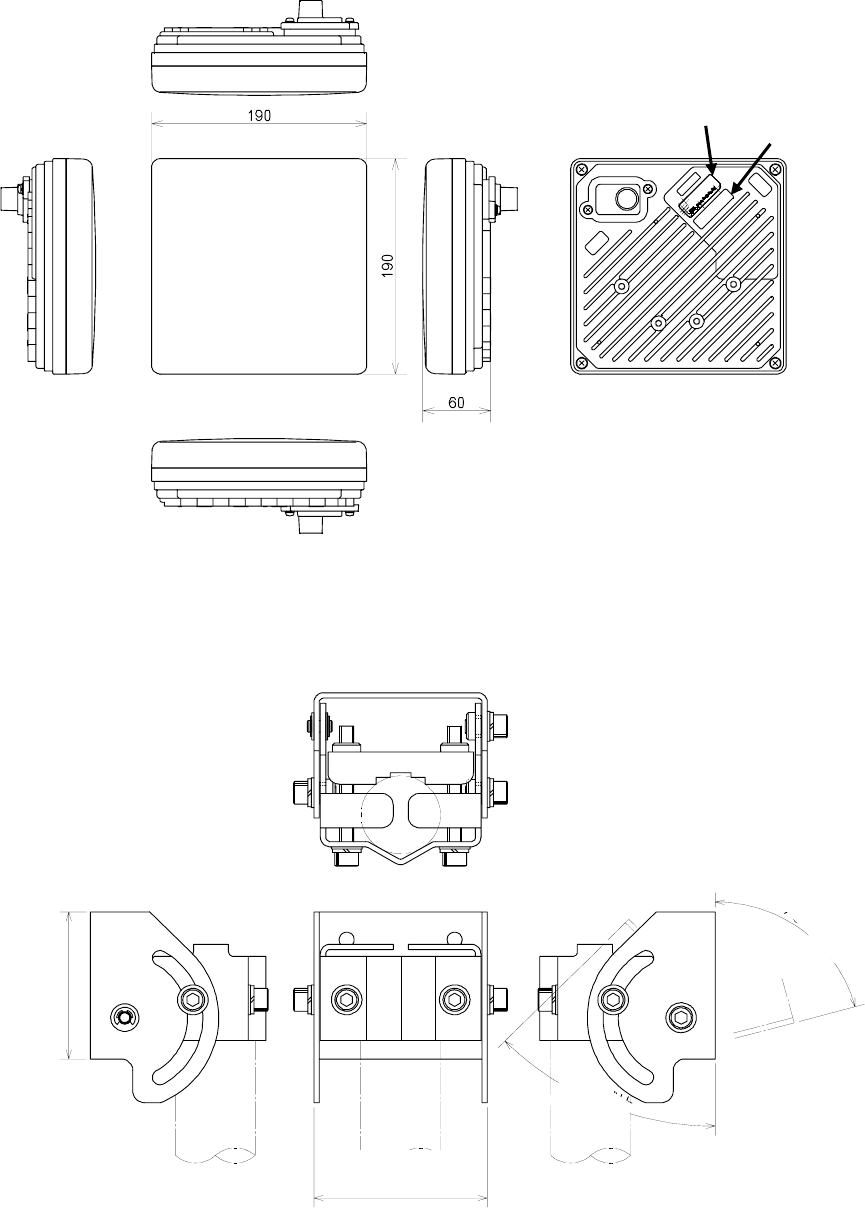
Figure 1-4 External View of the WT
DC 24V 0.7A
SER.
NO.
INPUT:
DATE :
TYPEW−WT<EL >
MADE INJA
PA
N
Generic
nameplate Nameplate for
this unit
External View of the WT
Figure 1-5 External View of the Outdoor Mounting Brackets for the WT
80 or less
45°or more
70 or less
75°or more
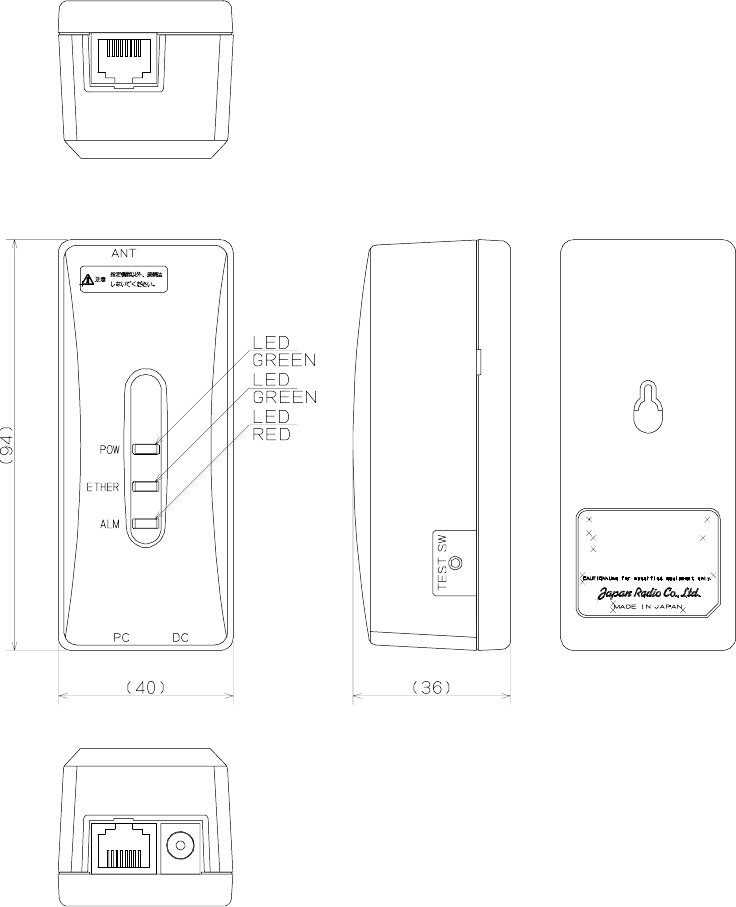
Figure 1-6 External View of the WT Adapter
MODEL NQD−2049
WT ADAPTER
1-9
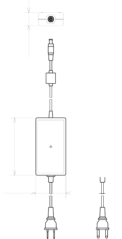
Figure 1-7 External View of the WT AC Adapter
120 or less
70 or less
30 or less

2-10
2. Specifications
2.1 General
Table 2-1 General
Transmit/Receve Band EL0 24.101-24.549 GHz
EL1 24.549-24.997 GHz
EL2 24.997-25.445 GHz
EH1 25.557-26.005 GHz
EH2 26.005-26.453 GHz
Channel spacing 28MHz (refer: Channel_arrangement)
Number of Remote Terminals 239 per Carrier
Duplex / Access Method TDD-TDM/TDMA
Modulation QPSK & 16-QAM, dynamic adaptive
Throughput/ RF Carrier QPSK: 23 Mbps Aggregate
16-QAM: 46 Mbps Aggregate
Protocols Supported 802.3, 802.1Q
Transmit output power QPSK AP:+14dBm,WT:-6dBm to +14dBm (ATPC)
16QAM AP+11.5dBm,WT:-8.5dBm to +11.5dBm (ATPC)
Frequency tolerance ±15ppm
Minimum receving level QPSK -79dBm or less
(BER=10-6)16QAM -69dBm or less
RF spectrum mask QPSK ETSI TypeA
16QAM ETSI TypeB
Occupied bandwidth QPSK 26MHz or less
16QAM 26MHz or less
Transmitter spurious emissions -30dBm/MHz or less
General

2-11
2.2 AP
Table 2-2 AP
2.3 WT
Table 2-3 WT
Antenna Beamwidth and Gain Omni(V/H) 360° : 6.5dBi
Sectoral(V/H) 90°x10°: 15.5dBi
Network Interface 100BASE-TX and 100BASE-FX(option)
Input Power -48vdc -/+5% , <0.8Amps
Physical RFU Dimensions:W190 x H190 x D362mm
Weight:3kg
IFU Dimensions:W275 x H325 x D165mm
Weight:14kg
Temperature -20℃ - +50℃,cold start at minimum -10℃ ambient
Humidity 20% - 80% , non-condensing
Access Point(AP)
-48VDC-/+20%、<0.8Amps
Wireless Terminai(WT)
Antenna Beamwidth and Gain Flat 4° : 31.5dBi or more
Network Interface 100BASE-TX
Input Power 100 -240vac , <0.5Amps
Physical RF Unit Dimensions:W190 x H190 x D70mm
Weight:2kg
Adapter Box Dimensions:W45 x H95 x D40mm
Weight:100g
AC Adapter Dimensions:W60 x H38 x D120mm
Weight:330g
Temperature -20℃ - +50℃,cold start at minimum -10℃ ambient
Humidity 20% - 80% , non-condensing
Weight:2.5kg
3. AP
3.1 AP-RFU
3.1.1 Overview
The AP-RFU consists of three blocks: Antenna section, RF section and IF section.
• Antenna section
The omni-directional antenna (with horizontal directivity of 360°) and the horn-type antenna ( 90° × 10°
directivity) give same shapes of AP-RFU.
• RF section
In the RF section, the transmission IF signals are up-converted into 24-26 GHz-band RF signals using the
local signal, which is generated by multiplying the 2.4 GHz synthesized oscillator. The next-stage BPF
eliminates unwanted sideband components. The up-converted 24-26 GHz-band RF signals are amplified up to
the desired level then fed to the antenna via the TDD-Switch and the Waveguide Filter.
The received 24-26 GHz-band RF signals by the antenna are fed in to the LNA via the Waveguide Filter and
the TDD-Switch. The output signals of the LNA are down-converted into IF signals using the local signal,
which is generated by multiplying the 2.4 GHz synthesized oscillator. The BPF is employed to eliminate the
image components (interference).
The TDD Switch selects the transmitting or receiving function. Detection of the transmiting burst at the IF
section turns the switch to the transmiting side.
• IF section
In the receiving IF section, the output level to the AP-IFU is adjusted by the automatic gain control (AGC)
function, so that the input level of the AP-IFU does not saturate for the reception of the WT signal which
gives highest receiving level. The SAW filter eliminates the adjacent channel interference.
In the transmitting IF section, the detection of the transmiting burst signal control the TDD-Switch in the RF
section to turn it to the transmiting side. The SAW filter provides the signal delay for the period of the burst
detection and the TDD-Switch turning time, as well as the elimination of the non-desired signal component.
The IF section also has the compensation functionarity for cable losses between the AP-RFU and AP-IFU.
The CPU in the IF section performs the AGC, the cable loss compensation , and the monitoring and control
functionalities.
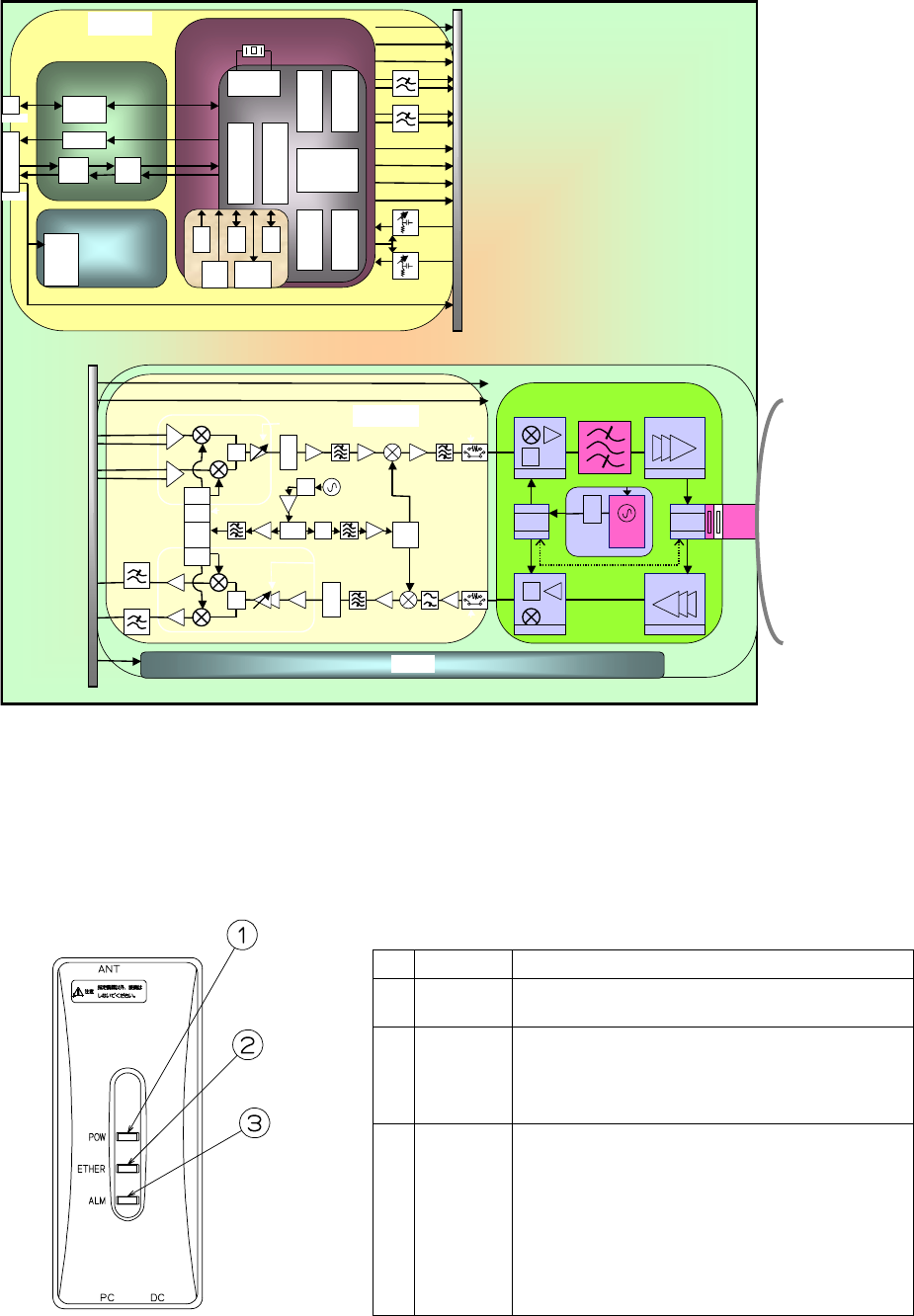
Figure 3-1 is a block diagram of the AP-RFU.
3-13
Figure 3-1 AP-RFU Block Diagram
3.1.2 Operations and Indications
The AP-RFU does not have any operation or indication panels.
3.2 AP-IFU
3.2.1 Overview
AP-IFU consists of three blocks: IF section, digital section and interface section.
• IF section
The transmission IF section performs quadrature modulation of 427.5MHz IF frequency according to the
transmission output from the digital modem installed in the WT-ASIC.
In the receiving IF section, the received burst signal level is adjusted by the automatic gain control (AGC)
function of the digital modem. The quadrature demodulator downconverts the received IF signal into the
baseband signal.
The digital section consists of a digital modem, TDD/TDMA framer, wireless MAC processor, and system
controller. These functionarities are equipped in the WT-ASIC.
The digital modem performs modulation and demodulation of transmitting and receiving burst signals.
The interface section has an interface between the AP and the upper unit (100BASE-TX). It provides a
100BASE-FX interface by installing the AP optical INTF unit.
to IFU
AP-RFU
WG
BPF
RF
SW
LNA
SW
2.4GHz
Synth
26G:×10
×n
×2
DOWN_CONV
TRSEL(RF)
PA
×2
UP_CONV
FREQ_CNT
IF部
HYB
ASK
MODEM
Temp
CNT D/A
D/A
AGC
×2
HYB
1282.5
MHz
ATPC
AGC
213.75MHz
MAX_HOLD/
AVERAGING A/D
TRCNT
Variable[20dB]
Temp
CNT
RFU
│
IFU
Cont
Temp Sens
VAR_ATT
[30dB]
CABLE
LOSS
DC+16V
LOGAMP
TMG
Gen
COMP TH
CNT
Obstacle
information
TRSEL(RF)
FREQ_CNT[DATLCLK/LE]
427.5MHz
SAW BPF
IF_Freq
1710MHz
SAW BPF
Horn
Antenna(V/H)
or
Omni
Antenna(V/H)
×3
BPF
SAW
BPF
IRF
Dielectric_BPF
LOGAMP
SAW_BPF
AGC2
RX_LVL
CNT
AUTO ON/OFF
AGC2
RFU-IF
AP-RFU_PS
Serge protection
Coax
CABLE
3-14
The digital section consists of the wireless MAC processor, TDD/TDMA controller, modem and system
controller. The wireless MAC processor converts between the Ethernet frames that the interface section
handles and wireless MAC frames. It also schedules the dynamic slot assignment. The TDD/TDMA
controller performs scrambling, encryption, error correction and other processing. The system controller
performs operating parameter setting, state monitoring, control and testing for the modem, TDD/TDMA
processor, wireless MAC processor and network interface. It also sends and receives maintenance signals via
SNMP. It performs delay control, authentication and other procedures, operating parameter setting, state
monitoring, control and testing for the subordinate WTs over a DMF channel.
The transmission IF section in the IF section performs quadrature modulation for the transmission baseband
signals at 427.5MHz LOC frequency for upconversion to IF signals. It also controls the output level to the
desired level based on the control from the ASIC. The receive IF section equalizes the level of the reception
waves arriving in a wide level range using the automatic gain control (AGC) from the ASIC, and then
downconverts them into baseband signals.
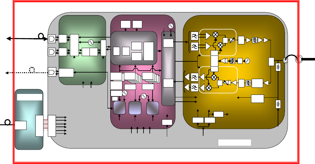
Figure 3-2 is a block diagram of the AP-IFU.
Figure 3-2 AP-IFU Block Diagram
AP-IFU
+5V
Regulat
0/9
0
HYB ×
2
0/
0
BAL
UNB
LC BPF
213.75MHz
LC_L +
5
LC BP
+
5
LC_L
digita
l
ATT
UN
B
-3.3V
+3.3_ +3.3_D
+5V
+16V
+16V
to RFU
Regulat
Regula
t
0/
0
0/9
0
ASK
MODEM
Interface part
PHY_RST
(FROM AP
L2SW_RST
(FROM AP
TRA
NS
LAYE
R2
SW
RJ-
45
RJ-
45
TRA
NS
PH
Y
TRA
NS TRA
NS
25MHz
RS-232C
driver/rec
i
4pin
MOJU
RA
MA
C
TDD
AP
-
Digital
U-CPU
15.62
5
Reset
IC TMP
SENS
20MHz
LVL
CNT_T/R
+16V(RFU)
+3.3V(for AP/MODEM-
ASIC,IF)
+2.5V(for AP-ASIC)
+1.8V(for U-CPU,D-
CPU,L2SW)
TT)
+2.5V
+3.3V
+1.8V
+3.3V
MOD
DEM
MODEM
ASIC
S-CPU
RT
FROM
64M
seria
l
EEPRO
SDRAM
8M×
D-CPU
FROM
16M
SDRAM
8M×
FROM
16M
SDRAM
8M×
27.83MHz
TX
RX
D-
FIF
O
D-
FIF
O
ED
C
2.5M
S_RST
[FROM_AP-ASIC]
D_RST
[FROM_AP-ASIC]
U_RST
[FROM_AP-
ASIC]
MODEM-
ASIC RST
+1.8V
+5V
Regula
t
+3.3_A
SIC
+1.5V
TDD_SELE
CT
IFU-MAC
(to PC)
DC-48V
Pow
suppl
y
conn
.
Power
supply
100BASE
TX
Pow
suppl
y
conn
.
IF part
SW
MOD_I
/Q
(BAL)
DEM_I/Q
(UNBAL)
to
RFU
Serge
protection
Serge
protection
Serge
protection
IFU-PS
Coax
CABL
E
3-15
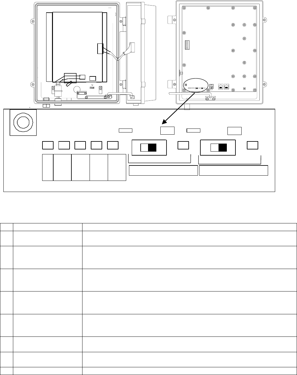
3.2.2 Operations and Indications
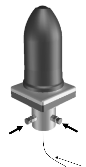
Figure 3-3 AP-IFU Operation and Indication Panel
Table 3-1 AP-IFU Indications
LED State indication
c POWER Lit green: Power on
Extinguished: Power off
d ETHER 1 Lit green: ETHER link established
Flashing green: ETHER signal sent or received
Extinguished: ETHER link down (See Table 3-3, 4)
e ETHER 2 Lit green: ETHER link established
Flashing green: ETHER signal sent or received
Extinguished: ETHER link down (See Table 3-3, 5)
f IFU STATE Lit red: IFU alarm (See Table 3-3, 2)
Flashing green: Normal (CPU running)
Flashing orange: During initialization
g RFU ALARM Lit red: RFU alarm (Cause: RFU failure (See Table 3-3, 1) or communication
error between the IFU and RFU (See Table 3-3, 3))
Extinguished: RFU alarm cleared
h ETHER1 AUTO Lit green: AUTO (ETHER1 AUTO switch set to AUTO)
Extinguished: 100BASE full duplex
i ETHER2 AUTO Lit green: AUTO
Extinguished: 100BASE full duplex
j RST Unit reset switch
制御盤LED部拡大図
26G-2-AP-PWR 26G-2-AP-CNT
POWER
ETHER
1
ETHER
2
IFU
STATE
RFU
ALARM
AUTO 100
FULL AUTO 100
FULL
ETHER1 AUTO ETHER2 AUTO
①②③④⑤ ⑥ ⑦
⑧

Table 3-2 AP-IFU Controls
Switch Description
1 ETHER1 AUTO
(The shape of the switch
may be changed)
Sets the ETHER1 interface (100BASE full duplex/AUTO).
After changing the switch setting, you have to reboot the unit (power off and
back on) to enable the new setting.
AUTO: AUTO
100FULL: 100BASE full duplex (factory setting)
2 ETHER2 AUTO
(The shape of the switch
may be changed)
Sets the ETHER2 interface (100BASE full duplex/AUTO).
After changing the switch setting, you have to reboot the unit (power off and
back on) to enable the new setting.
AUTO: AUTO
100FULL: 100BASE full duplex (factory setting)
Table 3-3 Alarm Issuance and Clear Conditions
Item Initial state Issued when: Cleared when:
The RFU-CPU detects LOCALM or
TRSELALM three times each for
more than 10msec.
The RFU-CPU detects no
LOCALM or TRSELALM
three times each for more
than 10msec.
LOCALM (local oscillator alarm)
occurs if the local oscillator lost
synchronization.
Synchronization is
recovered.
TRSELALM
(transmission/reception switchover
SW failure) occurs if the
transmission state continues for
more than 1sec.
Only by a reset.
1 RFU failure Cleared
IFU-CPU detects a RFU-IFU
communication error (monitoring
response).
IFU-CPU is cleared by a
single RFU-IFU
communication (monitoring
response).
Communication error among the
S-CPU, D-CPU and U-CPU.
No response to polling for 3sec
Cleared by a single
response.
2 IFU failure
Cleared
L2SW setting failure
If setting failed four times (once for
transmission and 3 times for
retransmission)
No recovery
3 Communication error
between RFU and IFU
Cleared The S-CPU detects a S-RFU-CPU
communication error.
No response to polling four times
(once for transmission and 3 times
for retransmission)
Cleared by a single
response.
4 ETHER 1 link down Issued PHY link down 3 times each for
100msec. Recovered from PHY link
down 3 times each for
100msec.
5 ETHER 2 link down Issued PHY link down 3 times each for
100msec. Recovered from PHY link
down 3 times each for
100msec.
4-17
4. WT
4.1 WT
4.1.1 Overview
The WT consists of the antenna section, RF section, IF section, digital section, interface section and
power supply.
• Antenna section
Uses a Triplate planar antennas to make the antenna compact and to provide a high gain.
• RF section
In the RF section, the transmission IF signals are up-converted into 24-26 GHz-band RF signals using
the local signal, which is generated by multiplying the 2.4 GHz synthesized oscillator. The next-stage
BPF eliminates unwanted sideband components. The up-converted 24-26 GHz-band RF signals are
amplified up to the desired level then fed to the antenna via the TDD-Switch and the Waveguide
Filter.
The received 24-26 GHz-band RF signals by the antenna are fed in to the LNA via the Waveguide
Filter and the TDD-Switch. The output signals of the LNA are down-converted into IF signals using
the local signal, which is generated by multiplying the 2.4 GHz synthesized oscillator. The BPF is
employed to eliminate the image components (interference).
The TDD Switch selects the transmitting or receiving function under the control of TDD/TDMA
framer installed in the WT-ASIC.
• IF section
The transmission IF section performs quadrature modulation of 427.5MHz IF frequency according to
the transmission output from the digital modem installed in the WT-ASIC. The SAW filter in the
next stage eliminates undesired out-of-band signals. The output level of the transmission IF secton
is adjusted by the automatic transmission gain control (ATPC) function of the digital modem.
.
In the receiving IF section, the SAW filter eliminates the adjacent channel interference. The
received burst signal level is adjusted by the automatic gain control (AGC) function of the digital
modem. The quadrature demodulator downconverts the received IF signal into the baseband signal.
• Digital section
The digital section consists of a digital modem, TDD/TDMA framer, wireless MAC processor, and
system controller. These functionarities are equipped in the WT-ASIC.
4-18
The digital modem performs modulation and demodulation of transmitting and receiving burst
signals.
The TDD/TDMA framer constructs and deconstructs radio burst frames. It alse performs scrambling,
encryption, and error correction functionarities.
The wireless MAC processor converts between the Ethernet frames and the wireless MAC frames in
the radio channel.
The system controller performs operating parameter setting, state monitoring, control and testing for
the entire unit. It also communicate with the AP processer via the DMF channel.
• Interface section
The interface section provides the physical interrfaces of Ethernet for user interface and serial
interface for the receiving level measurement terminal. It has a lightning surge protector to protect
the unit against external surges.
• Power supply
The power supply section generates various voltages used within the unit from +24V input power.
4-19
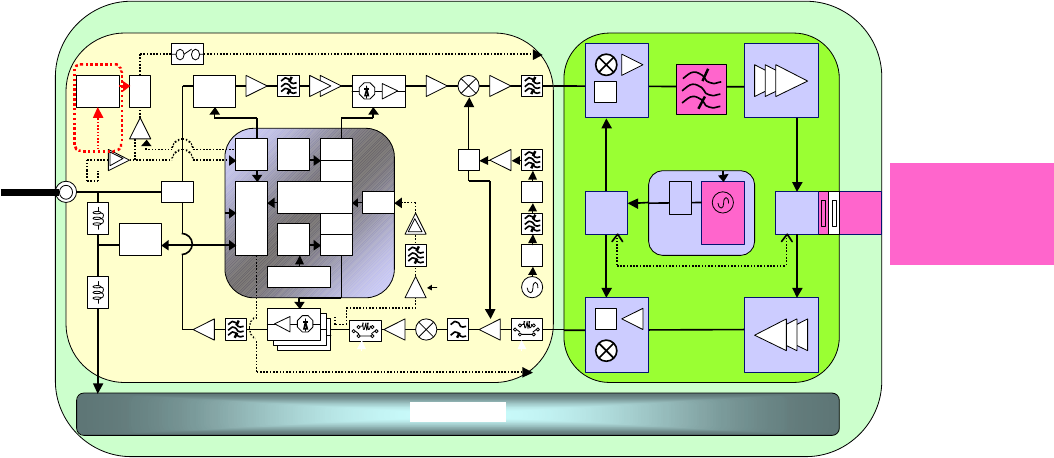
Figure 4-1 is a block diagram of the WT.
Figure 4-1 WT Block Diagram
4.1.2 Indications
(1) Indications
The indications on the WT adapter allows you to check the state of the WT.
Table 4-1 Indications on the WT Adapter
LED Indication
cPOW Lit green: Power on
Extinguished: Power off
dETHER Lit green: ETHER link established
Flashing green: Transmission or reception on
the ETHER port
Extinguished: ETHER link down
eALM Lit red: Wireless synchronization lost
Flashing red:
Flashing red for 500msec: Wireless
synchronization established (during
authentication)
Flashing red for 1 sec: VID use halted
Extinguished: Wireless synchronization
established (after authentication)
Figure 4-2 Indications on the WT Adapter
Interface part
Trans
Serge protection
PHY
RJ45
RS-232
DRV/REC
4P_MJ
LED DRV
MJ
MJ
MOD_I/Q(BAL)
DEM_I/Q(UNB)
Power supply part
(digital)
DC/DC
CONV
+3.3V_D(DIGITAL)
+3.3V_A(ANALOG)
+1.5V(for ASIC)
AGC(Analog)
TRSEL(RF)
X'TAL
MAC TDD
MOD
DEM
CPU
ASIC
ATPC(Analog)
DC+24V
AGC(Digital)
ATPC(Digital)
TRSEL(IF)
t
o
I
F
p
a
r
t
D/A
Conv
D/A
Conv
PLL
20MHz/80MHz
Signal processing part
FRASH
ROM
TEMP
SENS
PON
RST EEP
ROM SD
RAM
OFFSET_CNT
FREQ_CNT(RF)
Antenna
WG
BPF
RF
SW
LNA
SW
2.4GHz
Synth
26G:×10
×n
×2
DOWN
_
CONV
TRSEL(RF)
PA
×2
UP
_
CONV
FREQ_CNT
t
o
S
i
g
n
a
l
p
r
o
c
e
s
s
i
n
g
p
a
r
t
0/90
0/90
HYB
×2
0/0
213.75MHz
SW TRSEL(IF)
DEM_I/Q
AGC(Analog)
UNB
BAL
SAW BPF
DEM_IC
AGC(Digital)
0/0
WT-IF
MOD_IC
ATPC(Analog)
MOD_I/Q
×3 HYB
427.5MHz 1282.5MHz
IF_Freq
1710MHz
TRSEL(RF)
FREQ_CNT[CLK/DAT/LE]
BAL
UNB
SAW BPF
ATPC(Digital)
HYB
Dielectric
BPF
IRF
IF_Freq
1710MHz
SAW BPF
LC BPF
WT-MAC
WT_PS
WT

4-20
(2) State transition
The table below shows how each LED changes its state after the power is turned on until the unit
becomes operable.
Table 4-2 LED State Transition when the Power is Turned On
Immediately
after the power
is turned on
Several
seconds
after the
power is
turned on
Radio
synchronization
lost
Authenticating
after radio
synchronization
is reestablished
Operating after
authentication is
finished
Remarks
c POW Lit Lit Lit Lit Lit
d ETHER Extinguished
(Extinguished) Lit
(Lit) Extinguished
(Lit/Flashing) Extinguished
(Lit/Flashing) Extinguished
(Lit/Flashing) The state
within
parentheses
is that when a
PC is
connected.
e ALM Extinguished Lit Lit Flashing* Extinguished
*Flashing for 500msec. (On for 500msec. and off for 500msec.)
(3) Lighting conditions
The table below shows when the ALM LED lights.
Table 4-3 Lighting Conditions of the ALM LED in the Out-of-Service State
Out-of-service state Operation state Out of service Cleared
During authentication ALM LED=Extinguished ALM LED=Extinguished
During operation ALM LED=Flashing* ALM LED=Extinguished
Carrier off ALM LED=Extinguished ALM LED=Extinguished
*Flashing for one second (On for one second and off for one second)
5-21
5. INSTALLATION
5.1 Installing the AP-RFU and AP-IFU
5.1.1 Installing the AP-RFU (Omni Antenna)
Fix the AP-RFU (omni antenna) to a pole using the bolts c and d. At this time, extract the pigtail
cable that comes with the AP-RFU from the hole in the pole as shown in Figure 5-1.
Figure 5-1 Installing the AP-RFU (Omni Antenna)
Pigtail cable of the AP-RFU
cd
5-22
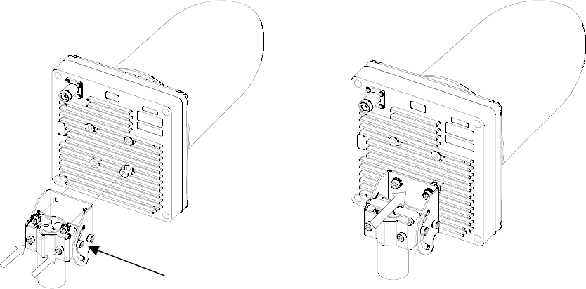
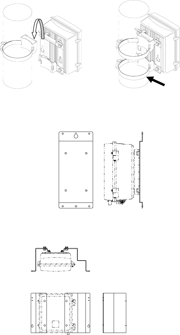
5.1.2 Installing the AP-RFU (Horn Antenna)
Attach the AP-RFU mounting bracket to the AP-RFU using the three bolts e as shown in Figure 5-3.
You can align the antenna either for vertical or horizontal polarization.
Fix the AP-RFU mounting bracket to the pole using the bolts c and d as shown in Figure 5-2.
Figure 5-2 Installing the Mounting Bracket Figure 5-3 Installing the AP-RFU (Horn Antenna)
① ②
③
A
P-RFU
mounting bracket
5-23
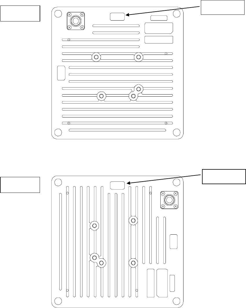
5.1.3 Setting AP-RFU (Horn Antenna) for Vertical or Horizontal
Polarization
Figure 5-4 Vertical Polarization
Figure 5-5 Horizontal Polarization
Vertical TOP V
TOP H
TOP V
Horizontal TOP H
TOP H
TOP V
5-24
5.1.4 Installing the AP-IFU
5.1.4.1 Installing the AP-IFU on a Utility Pole
Figure 5-6 Installing the AP-IFU on a Utility Pole
5.1.4.2 Indoor Installation
Figure 5-7 Indoor Installation
5.1.4.3 Installing the AP-IFU on a 19-inch Rack
Figure 5-8 Installing the AP-IFU on a 19-inch Rack
g
5-25
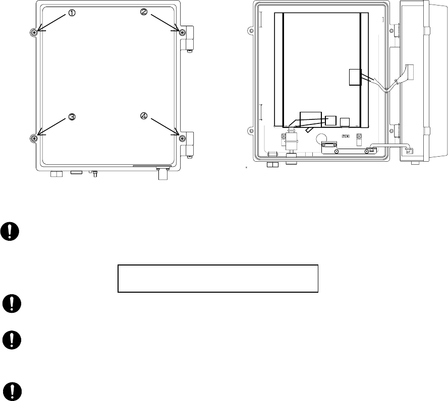
5.1.4.4 Opening and Closing the AP-IFU Cover
To open the cover:
(1) Loosen the special screws c to f to open the cover as shown in Figure 5-9.
(2) Fix the cover using the stopper g as shown in Figure 5-9.
To close the cover:
(1) Fix the stopper g on the main unit as shown in Figure 5-9.
(2) Close the cover and tighten the special screws c to f as shown in Figure 5-9.
Figure 5-9Opening and Closing the AP-IFU Cover
CAUTION: When opening the AP-IFU cover, make sure that the four special screws are loosened
completely. Forcing open the cover may damage it.
CAUTION: After you opened the AP-IFU cover, make sure to secure it using the stopper. Otherwise,
you may get hurt. To close the cover, be sure to return the stopper to the original position.
CAUTION: If it is difficult to tighten the four special screws of the AP-IFU cover, adjust the locations
of the screw holes (support the cover and align the top of the cover to that of the chassis) and tighten
the screws. Forced tightening of the screws may damage the cover and screws.
CAUTION: When closing the cover, be careful not to nick cables.
Use a T25 torx driver to open the AP-IFU
cover.
5-26
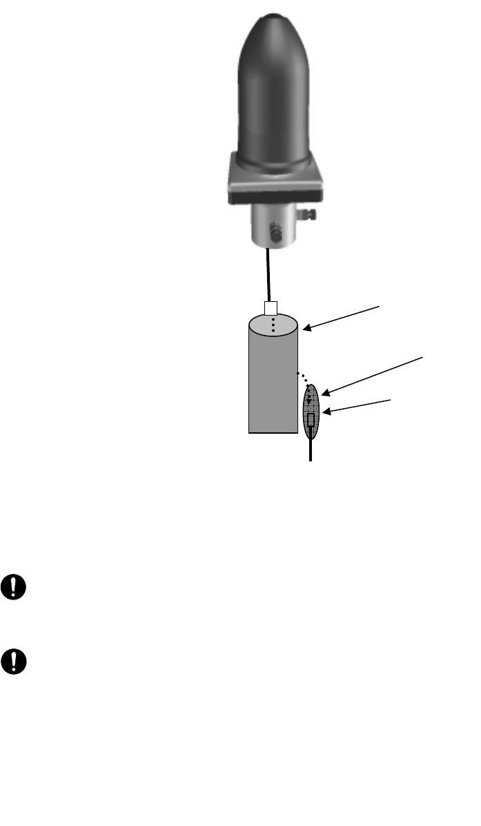
5.1.5 Connecting a Cable to the AP-RFU (Omni Antenna)
Figure 5-10 Connecting the Cable to the AP-RFU (Omni Antenna)
CAUTION: +16VDC to be supplied to the AP-RFU is superimposed on the signals in the IF cable.
Turn off the power to the AP-IFU when installing or removing the IF cable. Otherwise, the unit may
be damaged.
CAUTION: Cover the cable connection with a cold-shrinkable sleeve to make it waterproof.
Otherwise, water may get in the connection.
To the AP-IFU
Coaxial cable with an N
connector (IF cable)
Pole
Cold-shrinkable sleeve
5-27
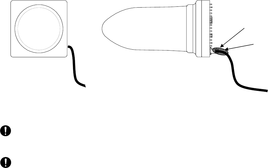
5.1.6 Connecting a Cable to the AP-RFU (Horn Antenna)
Figure 5-11 Connecting a Cable to the AP-RFU (Horn Antenna)
CAUTION: +16VDC to be supplied to the AP-RFU is superimposed on the signals in the IF cable.
Turn off the power to the AP-IFU when installing or removing the IF cable. Otherwise, the unit may
be damaged.
CAUTION: Cover the cable connection with a cold-shrinkable sleeve to make it waterproof.
Otherwise, water may get in the connection.
To the AP-IFU
Coaxial cable with
an N connector
Cold-shrinkable sleeve
(IF cable)
To the AP-IFU
5-28
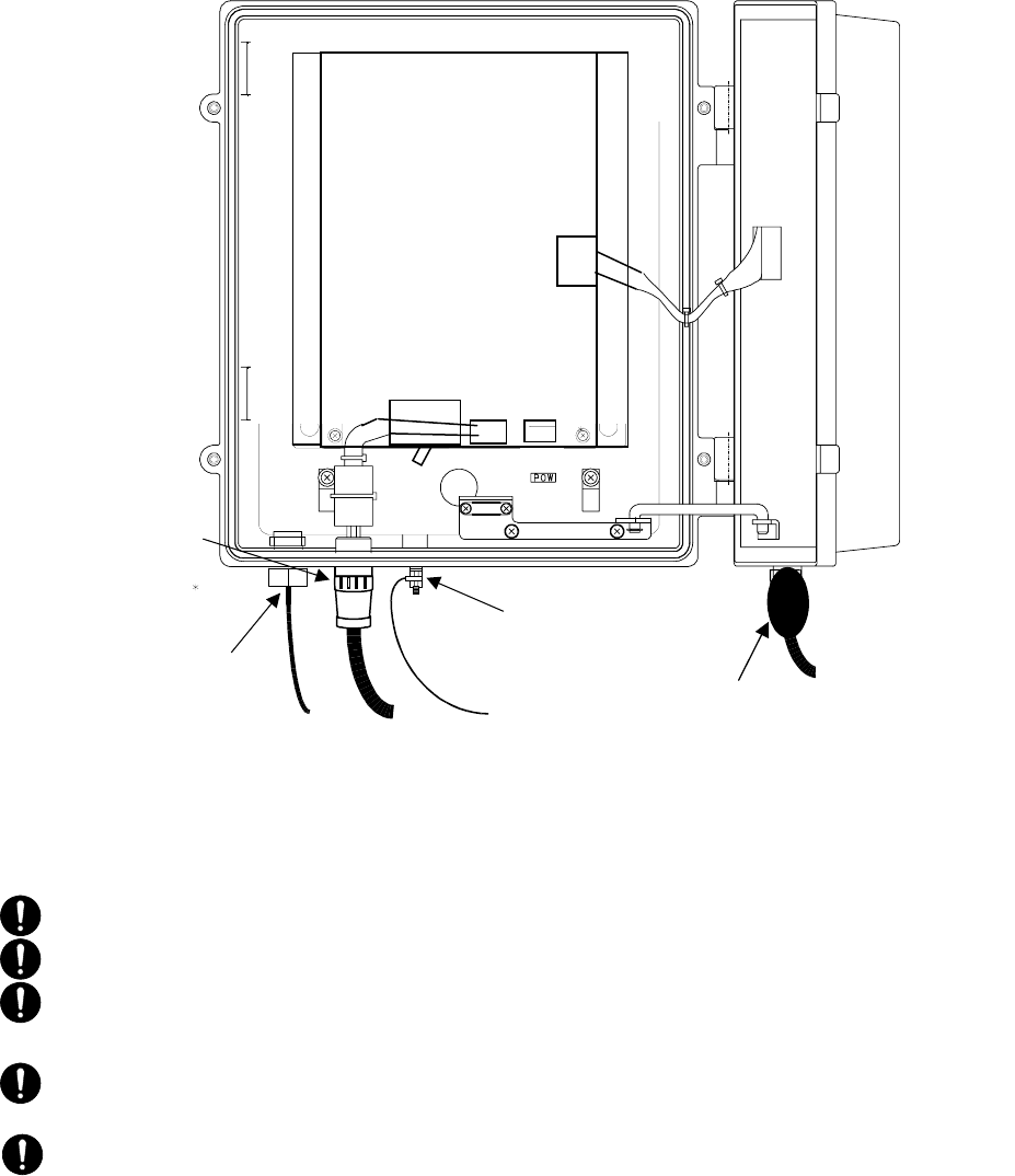
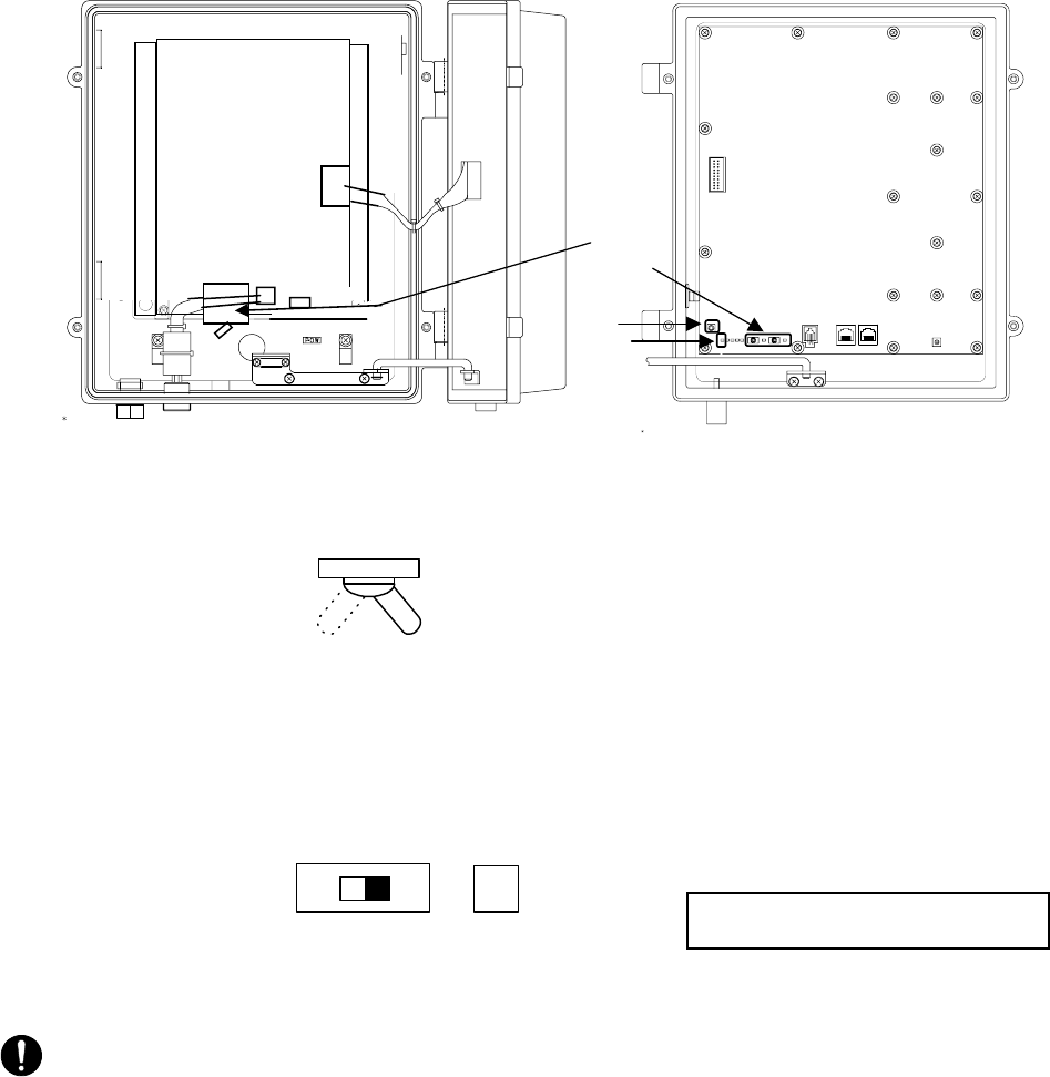
5.1.7 Connecting Cables to the AP-IFU
Connect four cables to the AP-IFU: a coaxial cable (with an N connector), optical cable, outdoor
power supply cable, and ground wire.
Figure 5-12-1 Connecting Cables to the AP-IFU (on the AP-PWR Side)
CAUTION: Ground wire more than 1.5□
CAUTION: FG terminal wire more than M4nut.
CAUTION: The DC -48V power supply voltage for AP-IFU shall be SELV or TNV-1 depending on
the network environment (0 or 1) acc. to IEC62102.
CAUTION: The Equipment for connection to AP-IFU Ethernet-interface(RJ-45) shall be appropriate
to connect to TNV-1 circuits.
CAUTION: For the connection Terminal Equipment to AP-IFU and a cables suitable for outdoor use shall
be installed.
Ethernet cable
Round connector for
the power cable
terminal
Ethernetl cable
inlet Ground wire
(More than 1.5□)
FG terminal
(More than M4nut)
Coaxial cable with an
N connector (IF cable)
Cold-shrinkable sleeve
Outdoor power supply cable for the AP
5-29
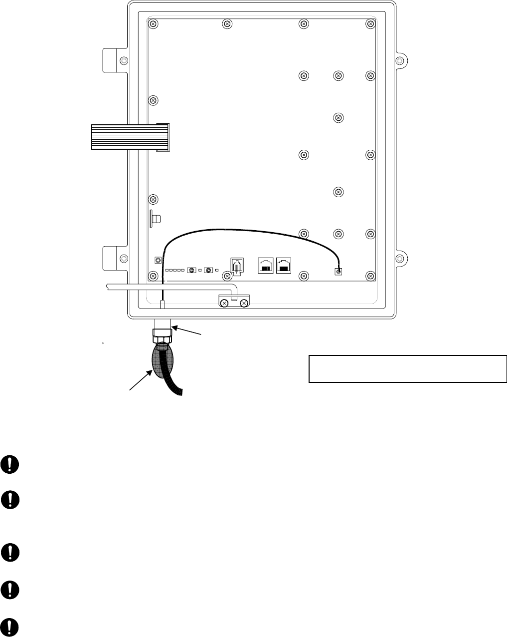
Figure 5-12-2 Connecting Cables to the AP-IFU (on the AP-CNT Side)
CAUTION: When opening the AP-IFU cover, make sure that the four special screws are loosened
completely. Forcing open the cover may damage it.
CAUTION: +16VDC to be supplied to the AP-RFU is superimposed on the signals in the IF cable.
Turn off the power to the AP-IFU when installing or removing the IF cable. Otherwise, the unit may
be damaged.
CAUTION: Cover the cable connection with a cold-shrinkable sleeve to make it waterproof.
Otherwise, water may get in the connection.
CAUTION: After you opened the AP-IFU cover, make sure to secure it using the stopper. Otherwise,
you may get hurt. To close the cover, be sure to return the stopper to the original position.
CAUTION: For the connection AP-IFU to AP-RFU and a coaxial cable suitable for outdoor use shall
be installed.
Use a T25 torx driver to open the AP-IFU
cover.
To the AP-RFU
Coaxial cable with an N
connector (IF cable)
IF terminal
Cold-shrinkable
sleeve
5-30
5.2 Installing the WT
5.2.1 Installing the WT
Attach the WT mounting bracket to the WT using the bolts c and d.
You can orient the WT either for vertical or horizontal polarization.
Secure the WT mounting bracket to the pole using the bolts.
Figure 5-13 Installing the WT
5-31
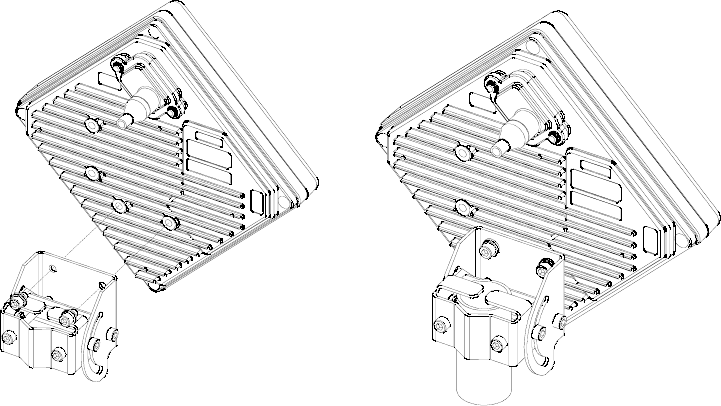
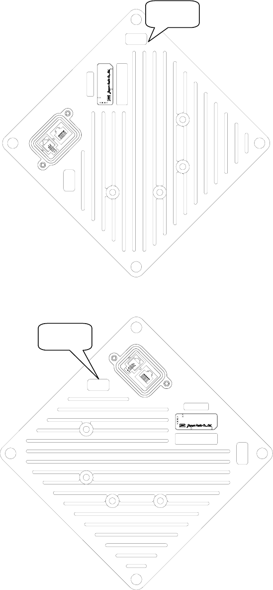
5.2.2 Setting the WT for Vertical or Horizontal Polarization
Rotate the antenna ninety degrees to choose between vertical or horizontal polarization
Figure 5-14 Vertical Polarization
Figure 5-15 Horizontal Polarization
DC24V 0.7A
SER.NO.
INPUT :
DATE :
MADE I N JAPA N
TYPEW−WT<EL >
TOP H
TOP V
TOP H
DC24V 0.7A
SER.NO.
INPUT :
DATE :
MADE IN JAPAN
TYPEW−WT< EL >
TOP H
TOP V
TOP V
5-32
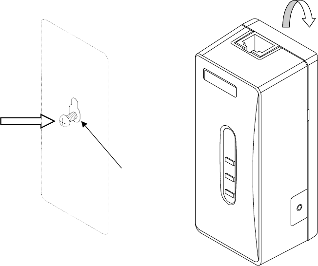
5.2.3 Installing the WT Adapter
Screw into the mounting position the wood screw that comes with the WT adapter, leaving 2 mm.
Hook the WT adapter on the wood screw.
Figure 5-16 Installing the WT Adapter on the Wall
Wood Screw
5-33
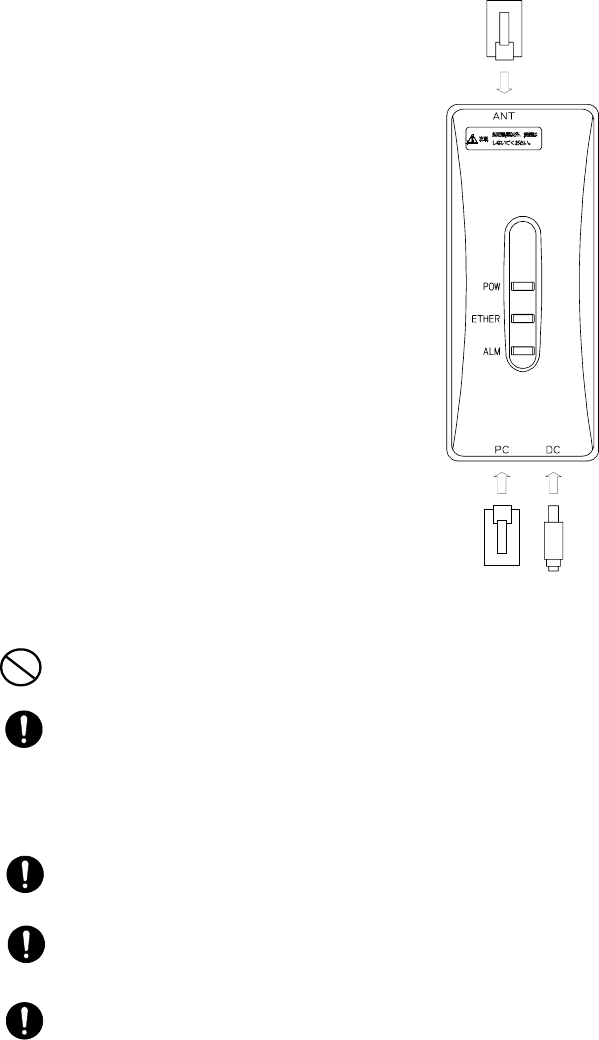
5.2.4 Connecting Cables to the WT Adapter
Connect three cables to the WT adapter: Ethernet cable to connect the WT, Ethernet cable to connect
the PC, and AC adapter cable.
(1) Specification for the Ethernet cable to connect the WT and WT adapter:
Straight
(2) Specification for the Ethernet cable to connect the PC (PC port):
To PC: Straight
To the hub: Cross
To the router: Straight
Figure 5-17 Connecting Cables to the WT Adapter
PROHIBITION: Never connect your personal computer to the ANT port of the WT adapter. Doing so
may damage your personal computer.
CAUTION: The cable connecting between the WT and WT adapter carries 24 VDC for the WT in
addition to Ethernet signals. Before unplugging the cable connecting between the WT and WT adapter,
make sure to unplug the DC jack of the WT adapter to turn the power off. Otherwise, the unit may be
damaged.
CAUTION: The cable connecting the WT and WT adapter is a straight cable. Wrong connection may
damage the unit.
CAUTION: The Equipment for connection to WT adapter PC-interface(RJ-45) shall be appropriate to
connect to TNV-1 circuits.
CAUTION: For the connection WT adapter to WT and a cable suitable for outdoor use shall be
installed.
To your PC To the AC
d
To the WT

5-34
5.3 Standard Tools to be Used
The table below lists the tools used during installation or maintenance of the units.
Table 5-1 Tools Used
No. Unit name Used for: Tightening
torque [N•cm] Tool
1 Door M5 265 Torx driver (VESSEL T25H-120)
2 Power board M4 127 Phillips screwdriver
3 Cable clamp M4 127 Phillips screwdriver
4 Power board M4 127 Phillips screwdriver
5 Cable clamp M4 127 Phillips screwdriver
6 Ground M4 nut 127 Socket driver (Width across flats: 7)
7 SC lock M16
nut 80 to 120 Spanner wrench (Width across flats: 22)
8 MC mounting
plate M3 57 Tightened manually
9 Mounting plate M8 1080 Socket wrench (Width across flats: 13)
10 MC mounting
feet M3 57 Socket driver (Width across flats: 5.5)
11
AP-
IFU
MC mounting
feet (for cascade
connection)
M4 130 Phillips screwdriver
12 Small window M4 127 Torx driver (VESSEL T20H-120)
13 Mounting
bracket M5 265 Allen wrench (Width across flats: 5)
14 WT
Ethernet cable Crimping tool for RJ-45
(Release-after-crimp type)
15 AP-RFU
(Omni) Mounting
bracket (axis
tightening)
M16 9410 Socket wrench (Width across flats: 24)
16 AP-RFU
(Horn) Mounting
bracket M5 265 Allen wrench (Width across flats: 5)
The appropriate tightening torque is ±10% of the value indicated in the table.
5-35
①
②
③
④
5.4 Switches
5.4.1 Switches on the AP-IFU
Figure 5-18 Switches on the AP-IFU
c Power switch
This is the switch to supply power to the AP-IFU and AP-RFU.
d ETHER1/ETHER2 switch
This is the switch to set AUTO or 100FULL.
(The shape of the switch may be changed.)
e RST switch
This is the switch to reset the unit.
CAUTION: After changing the switch setting, you have to reboot the unit (power off and back on) to
enable the new setting.
f POWER LED
When on : Lit green
When off: Extinguished
Factory setting: 100FULL
ETHER AUTO LED
AUTO: Lit green
100FULL: Extinguished
100
FULL
AUTO
ETHER1 AUTO
ONOFF
5-36
5.4.2 Switches on the WT Adapter
Figure 5-19 Switches on the WT Adapter
c TEST SW switch
This is the switch to check for any disconnection on the Ethernet cable connecting the WT
and WT adapter.
CAUTION: If you turn on this switch, the Ethernet signal is looped back to the WT and not output to
the PC port.
How to check for a disconnection:
• Unplug the cable from the PC port of the WT adapter.
• Make sure that the ETHER LED lights.
• Hold down the TEST SW switch.
• (The Ethernet signal from the WT is looped backed to the WT via the WT adapter.)
• The connection is normal if the ETHER LED lights green.
• The four Ethernet signal lines have a disconnection or wrong wiring if the ETHER LED
remains extinguished.
CAUTION: The TEST SW cannot identify a wrong connection for the straight/cross cable. When
connecting a connector, make the correct connection for the straight or cross cable.
CAUTION: If you turn on this switch by mistake, the Ethernet signal is looped back to the WT and
not output to the PC port.
c
ETHER LED
PC port
5-37
5.5 Connectors
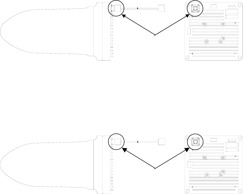
5.5.1 Connecting the AP-RFU and AP-IFU
Figure 5-20 Connecting Section of the AP-RFU (Omni Antenna)
c IF terminal: Pigtail connector (connector type: N-J)
Connect the coaxial cable with an N-type connector from the AP-IFU.
Figure 5-21 Connecting Section of the AP-RFU (Horn Antenna)
c IF terminal: (Connector type: N-J)
Connect the coaxial cable with an N-type connector from the AP-IFU.
TOP H
TOP V
cFrom/to the IFU
TOP H
TOP V
cFrom/to the IFU
5-38
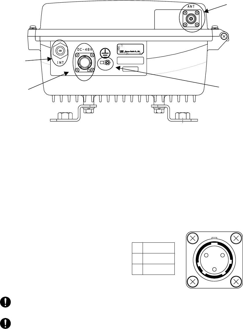
5.5.2 Connectors on the AP-IFU
Figure 5-22 Connecting Section of the AP-IFU (Bottom View)
c ANT terminal: (Connector type: N-J)
Connect the coaxial cable with an N-type connector from the AP-RFU.
d Ethernet cable inlet:
Insert the Ethernet cable into the rubber bushing.
e FG terminal:
Connect the ground wire.
f Power cable terminal: (Connector type: Round)
Connect the power cable.
1 GND
2 DC-48V
3 NU
CAUTION: Power cable terminal(④): The DC -48V power supply voltage for AP-IFU shall be SELV
or TNV-1 depending on the network environment (0 or 1) acc. to IEC62102.
CAUTION: Ethernet cable inlet(②):The Equipment for connection to AP-IFU Ethernet-interface
(RJ-45) shall be appropriate to connect to TNV-1 circuits.
SER.NO.
INPUT :
DATE :
MADE IN JAPAN
TYPEW−AP<EL0>
DC−48V 0.8A
f e
d
c
12
3
5-39
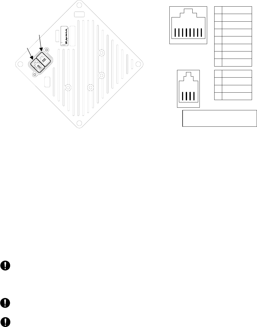
5.5.3 Connectors on the WT
Figure 5-23 Connecting Section of the WT
c ETHER port
This is the port to connect the WT to the WT adapter. Use a straight cable between the WT
and WT adapter.
Shape: RJ45 connector
Specification: Ethernet signal (MDI specification)
The four remaining idle conductors are used for power and LED control.
When connecting the receiving level measurement terminal, connect battery to this port.
d Receive level measurement terminal port
This is the port to connect the receiving level measurement terminal.
Shape: RJ-22
Connect the receiving level measurement terminal to this port using the WT connection
cable (that comes with the receive level measurement terminal).
CAUTION: The cable connecting between the WT and WT adapter carries 24 VDC for the WT in
addition to Ethernet signals. Before unplugging the cable connecting between the WT and WT adapter,
make sure to unplug the DC jack of the WT adapter to turn the power off. Otherwise, the unit may be
damaged.
CAUTION: The cable connecting the WT and WT adapter is a straight cable. Wrong connection may
damage the unit.
CAUTION: When closing the small window, make sure that the rubber packing of the small window
is free from any foreign matter.
Use a T20 torx driver to open
interface cover
4 3 2 1
1
2
3
4
TXD
RXD
NU
GND
②
8 7 6 5 4 3 2 1
1
2
3
4
5
6
7
8
TXD+
TXD-
RXD+
LED1
LED2
RXD-
+24V _IN
GND
①
DC24V 0.7A
SER.NO.
INPUT :
DATE :
MADE IN JAPAN
TYPEW−WT<EL >
TOP H
TOP V
①
②
5-40
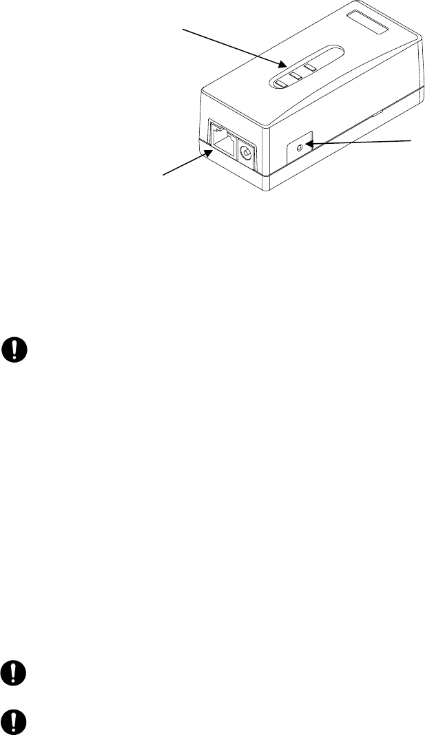
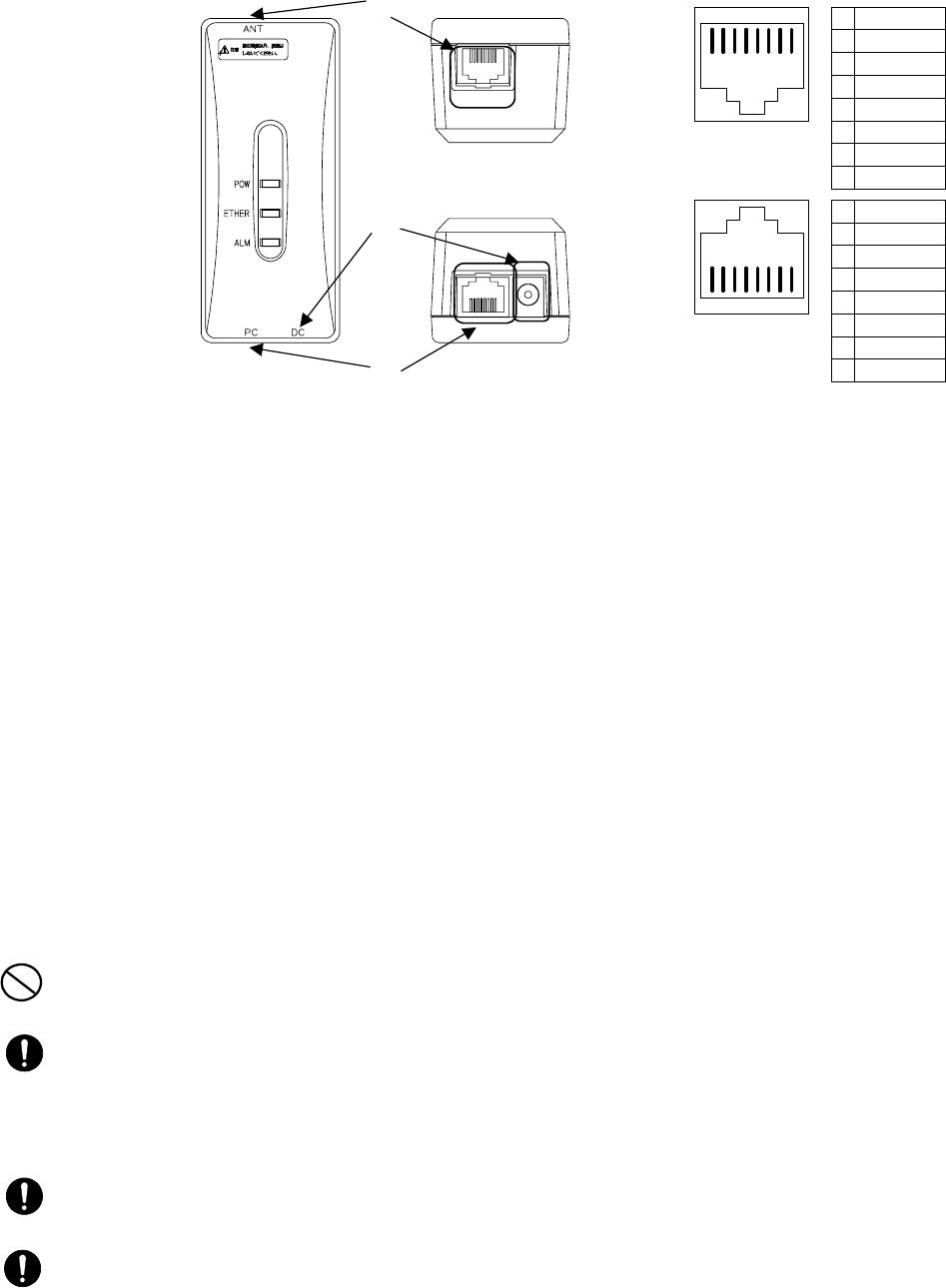
5.5.4 Connectors on the WT Adapter
Figure 5-24 Connecting Section of the WT Adapter
c ANT port: (Connector type: RJ-45)
This is the port to connect the WT to the WT adapter. Use a straight cable between the WT
and WT adapter.
Shape: RJ45 connector
Specification: Ethernet signal (MDI-X specification)
The four remaining idle conductors are used for power and LED control.
d PC port: (Connector type: RJ-45)
This is the port to connect the communication terminal.
Shape: RJ45 connector
Specification: Ether signal (MDI-X specification)
Connect the local management tool terminal using a straight cable.
Use a cross cable to connect the hub.
Use a straight cable to connect a PC or router.
e DC jack: (+24VDC power supply)
Connect the AC adapter that comes with the WT.
PROHIBITION: Never connect a communication terminal to the ANT port of the WT adapter. Doing
so may damage your personal computer.
CAUTION: The cable connecting between the WT and WT adapter carries 24 VDC for the WT in
addition to Ethernet signals. Before unplugging the cable connecting between the WT and WT adapter,
make sure to unplug the DC jack of the WT adapter to turn the power off. Otherwise, the unit may be
damaged.
CAUTION: The cable connecting the WT and WT adapter is a straight cable. Wrong connection may
damage the unit.
CAUTION: PC port: (Connector type: RJ-45 ②)The Equipment for connection to WT adapter
PC-interface(RJ-45) shall be appropriate to connect to TNV-1 circuits.
②
8 7 6 5 4 3 2 1
1
2
3
4
5
6
7
8
RXD+
RXD-
TXD+
NU
NU
TXD-
NU
NU
1
2
3
4
5
6
7
8
RXD+
RXD-
TXD+
LED1
LED2
TXD-
+24V _OUT
GND
①8 7 6 5 4 3 2 1
Top view
Bottom view
e
c
d