Japan Radio NTG420 Solid State Transmitter-Receiver User Manual Usera manual Installation
Japan Radio Co Ltd. Solid State Transmitter-Receiver Usera manual Installation
Contents
- 1. Usera manual(Installation)
- 2. Users manual(Operation)
Usera manual(Installation)

7ZPRR0001
INSTALLATION MANUAL
FOR
THE NTG-420 SOLID STATE
TRANSMITTER-RECEIVER
Document No. 7ZPRR0001
APR. 2016
7ZPRR0001
1
Table of Contents
1. SELECTING THE INSTALLATION POSITION .................................................................. 2
2. INSTALLATION PROCEDURE.......................................................................................... 7
3. CONNECTING THE INSTALLATION CABLE ................................................................. 10
4. INSTALLATION OF SOLID STATE TRANSMITTER-RECEIVER (NTG-420) .................. 12
5. SOLID STATE TRANSMITTER-RECEIVER(NTG-420) WIRING ..................................... 13
6. INSTALLATION CABLE AND WAVEGUIDE ................................................................... 17
APPENDIX .......................................................................................................................... 20
MAXIMUM PERMISSIBLE EXPOSURE(MPE) CALCULAT ION.......................................... 29
FCC CAUTION .................................................................................................................... 31
IC (INDUTRY CANADA) ...................................................................................................... 31
7ZPRR0001
2
- Preface -
This instruction manual describes installation method of the NTG-420
Transmitter-Receiver. This manual describes radar system configuration with
X-band Radar Antenna and NCD-2247-1B PC type radar monitor display as an
example.
1. Selecting the installation position
1) Physical selection criteria
• Install the antenna at the center of the mast on the keel line.
• If the antenna cannot be installed at the above position for some reason, the
amount of deviation must be minimized. And, reinforce the mount base
and the platform and take precautions to protect the antenna from vibration
and impact at the installation position.
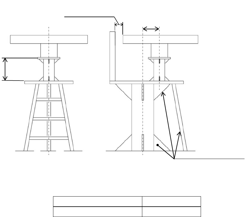
• To avoid the radiating section coming in contact with other installed objects
while it is rotating, ensure that there is at least 200 millimeters from the
swing circle (turning radius) to other installed objects (Fig.1-1). The swing
circle of the X-band Radar Antenna is as shown in Table 1-1.
Fig.1-1 Installation of antenna
Table 1-1 Swing circle
Antenna Swing circle
X-band Radar Antenna 2825mm
min-height
必要最小高さ
min-offset
オフセット最小
Over 200mm
200mm
以上
reinforcing member
補強材
7ZPRR0001
3
• Avoid having a rope or signal flag from winding around the radiating section
thereby preventing it from rotating.
• Avoid the effects of dust and heat caused by smoke from a chimney.
• When determining the appropriate antenna height and installation location,
take into consideration the reduction of vibration, the strength of the hull and
the antenna mount base, and maintenance properties.
• Provide for maintenance space: platform, safety link, hand rail, steps, etc.
The lower edge of a radar antenna should be a minimum of 500 mm above
any safety rail.
• When installing the antenna, select a location where there are the fewest
structural objects in the surrounding area so that the capability to drive the
motor will not be depressed by the non-equability wind which is likely to
rotate the antenna.
2) Electrical selection criteria
• The installation height of the antenna relates to the maximum detection
distance. The higher is the better. (However, if it is too high, radio wave
energy greatly attenuates above the antenna's vertical beam width (the
point -3dB from the peak of the main lobe). As a result, it is difficult to
detect a close-in target. Sea clutter also increases. Determine the
installation height by taking into consideration the weight, maximum length
of the cable, and maintenance after installation.
• If the installation height of the antenna is low, it is difficult to detect a long
distance target. The ship's mast, derrick, and construction objects interfere
with radiating beam causing the range that cannot be viewed on the radar
display to increase.
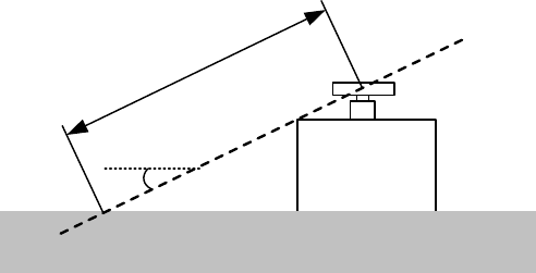
Generally, the lowest antenna installation position is supposed to be on the
A-B line shown in Fig.1-2. In the case of the radar antenna, 2θ equals 20°.
Specifically, the antenna position is normally elevated so that the building
etc do not interfere with radiating beam. The inside of A point might be blind
area due to antenna beam does not propagation. So, if near distance should
be covered, antenna installation position must be considered carefully.
θ = 10°
L
A
B
θ
Sea surface Blind are a
Building etc.
Fig.1-2 Antenna installation height vs Vertical beam width
7ZPRR0001
4
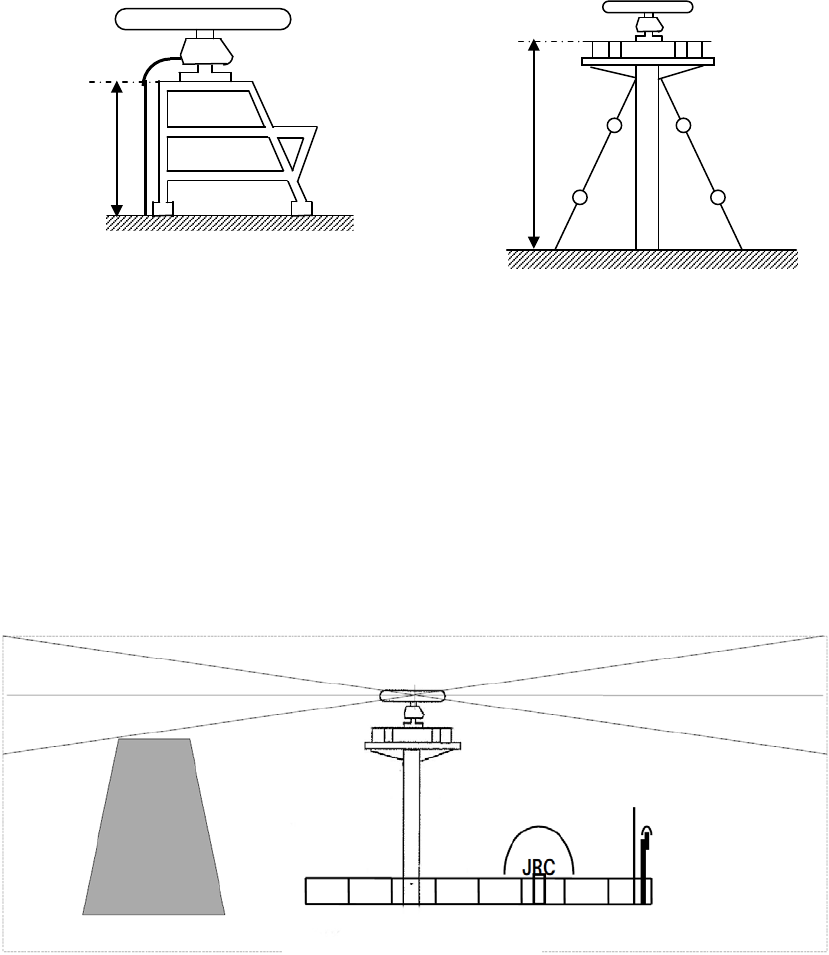
• If it is considered that sufficient installation height cannot be provided when
the antenna is installed directly on the roof of the building, use a mounting
rack or radar mast (Fig.1-3). Normally, when the antenna installation
height is less than 2 meters from the roof of the building, provide a
mounting rack assembled at an angle frame to install the antenna. When
the antenna installation height is 2 meters or higher from the roof of the
building, provide a cylindrical radar mast to install the antenna. Consider
the convenience of the service staff who take care of installation,
maintenance, adjustment, and repair of the antenna by providing adequate
footholds to the mounting rack and the radar mast.
Fig.1-3 Mounting rack and mast for the antenna
• When installing the antenna, select a location where there are the fewest
structural objects in the surrounding area so that false images which
interfere with target detection will not be generated by signal reflection from
other antennas, equipments, and cargos. Only as a guide, note that
structural objects should not exist within the range of the vertical beam
width (Fig.1-4).
Vertical beam width of X-band Radar Antenna: Approx. 20° (±10.0° when
the height of the radiating section is 0°).
Fig.1-4 Antenna and the surrounding structural objects
ビーム幅
Beam
width
Installation
Installation
7ZPRR0001
5
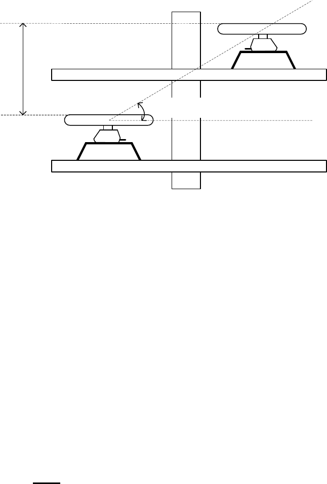
• When installing two or more antennas, antennas in close proximity should
have a minimum vertical elevation separation angle of 20 and a minimum
vertical separation of 1m where possible, so that those antennas do not
enter each other's vertical beam width range.
1m (min)
20°(min)
Fig.1-5 Installing two or more antennas
• To avoid interference with other equipment and to prevent radio noise from
generating, do not place the VHF antenna, AIS/GPS antenna, and
VSAT/INMARSAT's dome within the range of the vertical beam width.
* If there is a concern that structural objects existing within the vertical beam
width may generate false images, equip the structural objects with a radio
wave absorber. (There are two types of absorbers: broadband type
having no specific resonant frequency and narrowband type which can
absorb a band with a specific frequency. Use those where applicable.)
Furthermore, it is effective to install a metal reflector, which reflects radio
waves upwardly, between the antenna and a structural object so that the
radar's radio wave will not directly come in contact with the structural
object.
When the structural objects exist in the surrounding area of Antenna unit,
the false echo may appear. The sector blank function is effective to
reduce the signal reflection from the structural objects. Because of it can
stop transmission. Therefore, it may reduce the false echo appearance.
Note: Because most radio wave absorbers have poor durability, some
must be replaced every year. When installing a reflector, the
area to the rear of the reflector becomes a blind sector.
Therefore, minimize the size of the reflector.
When the sector blank function set to on, ensure a sufficient
view field in the surveillance area.
* The above procedures for selecting an antenna installation position are
described based on the radar's antenna. Comprehensively select the
antenna position by considering other antennas' installation procedure
manual, building tower mast structure, strength of the selected position,
and vibration.
3) Confirmation during test run
7ZPRR0001
6
If the antenna vibrates a lot during test run, try to reduce or prevent
vibration by reinforcing the antenna mount base or using wire stays
attached to the radar mast.
4) Others
• The design of the mounting platform for the antenna should take into
account the vibration requirements defined by IEC 60945.
Vibration
Frequency
2 to 13.2Hz
13.2 to 100Hz
Amplitude +/-1mm +/-10%
Acceleration 7m/s
2
constant
• All installations should facilitate protection of equipment, including cabling,
from damage.
The cables should be kept as short as possible to minimize attenuation of
the signal.
• Crossing of cables should be done at right angles(90°) to minimize
magnetic field coupling.
• Eliminating the interference on frequencies used for marine
communications due to operation of the radar. All cables of the radar are to
be run away from the cables of radio equipment. (ex. Radiotelephone.
Communications receiver and direction finder, etc.) Especially inter-wiring
cables between antenna unit and display unit of the radar should not be run
parallel with the cables of radio equipment.
• Cable should not be exposed sharp bends.
• The grounding of equipment units should be carried out according to this
manual.
5) After installation
After you have completed the installation work, check and test the
installation work with customer(s) and confirm with each other.
7ZPRR0001
7
2. Installation procedure
1) Precautions for transporting and storing the antenna
• An antenna is a heavy load. Be very careful about handling it.
• Do not allow the antenna fall on its side while it is stored or being installed.
• Do not apply rope to the antenna in the way that squeezes or deforms the
radiating section.
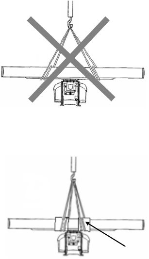
• When hoisting the antenna by a crane, do not hoist it by attaching a belt or
a rope only to the antenna's radiating section as shown in Fig.2-1.
• When lifting the antenna(Fig.2-2):
Wrap a cloth around the antenna's support section located at the bottom of
the radiator, and then attach a belt to it to lift the antenna.
Fig.2-1 Improper way to hoist
Fig.2-2 Lifting the Antenna
2) Installation procedures
a) Maintain a flat level surface on which to install the antenna.
• Use sufficiently thick steel material and reinforcement material for the
antenna's installation surface (mount base) to reduce vibration and
impact. Keep the mount base flat and smooth.
• If there is a partial gap between the mount base and the antenna
chassis's legs, work on the installation surface so that it becomes flat
and smooth. If a gap exists and the antenna is tightly clamped, the
chassis will distort and become damaged by vibration.
Wrap a cloth

7ZPRR0001
8
b) Avoid using vibration-proof rubber and resin
• Do not insert an elastic body, such as vibration-proof rubber or resin,
between the mount base and the antenna chassis' legs. If rubber or resin
is inserted, the amplitude of vibration increases, resulting in the possibility
of damage to the antenna. Furthermore, if installation bolts become loose
due to deterioration of rubber or resin, the antenna may be damaged or fall
from its mount.
3) Installation and clamping method
a) Installation direction
• Installation should be done so that the cable gland side is oriented
accessibility by maintenance staffs.
b) Bolts, nuts and tightening torque to be used
• Use stainless steel bolts for the antenna and uniformly tighten all of the
bolts using double nuts for each bolt so that the antenna will not
become loose (Table 2-1).
• Although the length of the bolt will differ according to the thickness of
the mount base, use a bolt long enough so that more than 4 millimeters
of thread protrudes beyond the double nuts after the double nuts have
been tightened.
Table 2-1 Length of antenna mounting bolts and tightening torque
Antenna
Unit
Thickness of
Mount Base
(mm) Bolt Torque (N-m)
12 M10×55(mm) SUS304 40
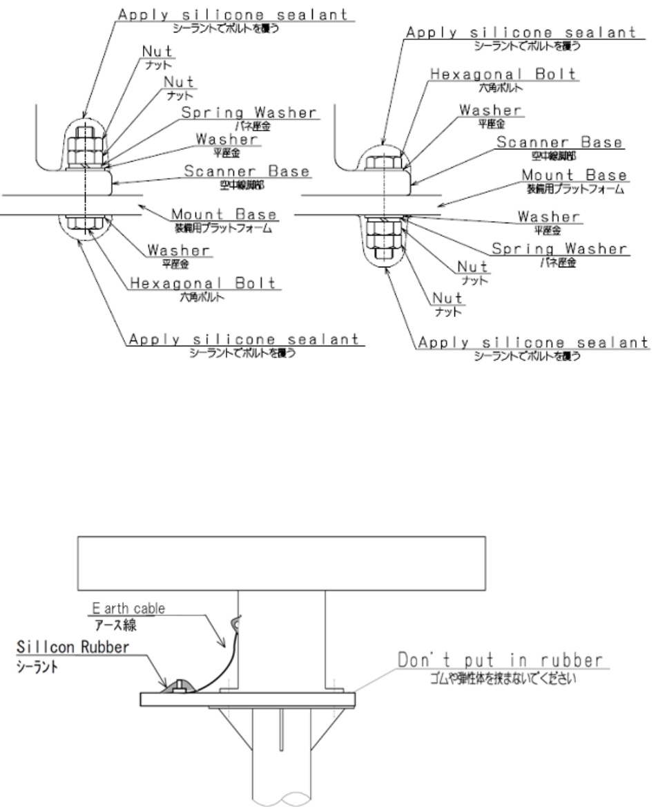
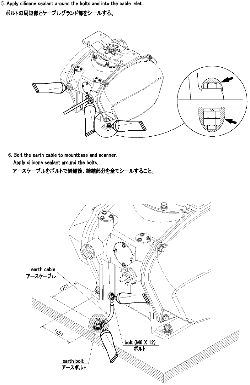
c) Use of washer and corrosion-resistant measures
• At the location where a bolt's head or nut comes in contact with the
antenna chassis' legs and the mount base, insert a plain washer which
fits the bolt; and, at the location where the nut comes in contact with the
plain washer, insert a spring washer, and then securely tighten the nuts
(Fig.2-3).
• To prevent corrosion due to the contacts between different metals, such
as the antenna chassis' legs, installation surface, bolts, nuts, etc., cover
the bolt's head and nuts with sealant (Fig.2-3).
7ZPRR0001
9
Fig.2-3 Use of washer and corrosion-resistant measures
d) Grounding and corrosion-resistant measures
• Ground the antenna chassis and the installation surface (hull) by using
an earth line. Apply sealant to the connection portion of the earth line
to prevent corrosion and damage by vibration (Fig.2-4).
Fig.2-4 Grounding and corrosion-resistant measures
7ZPRR0001
10
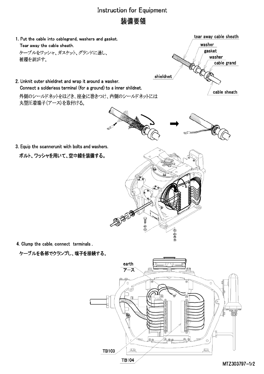
3. Connecting the installation cable
7ZPRR0001
11
7ZPRR0001
12
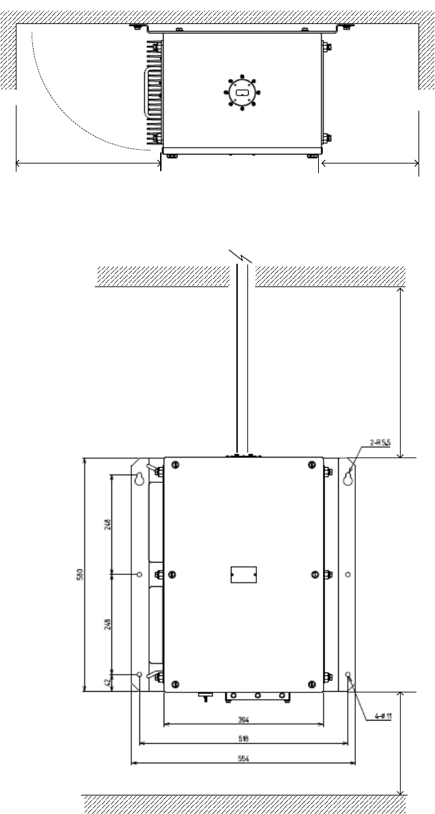
4. Installation of Solid State Transmitter-Receiver (NTG-420)
The mounting place of NTG-420 Solid State Transmitter-Receiver is shown below. It is
required to secure a space for equipment and maintenance.
Fig.4-1 NTG-420 Installation (Space for Mounting Place)
Min. 250
Waveguide
Min. 400
Min. 250Min. 370
7ZPRR0001
13
5. Solid State Transmitter-Receiver(NTG-420) Wiring
Table 5-1 Connect Terminal of NTG-420
Terminal No. Connect Cable
Waveguide
flange(UG-51/U)
X-band 9ft Antenna
WRJ-9
Waveguide)
P1
DC Power Supply
(DC 48V)
Power Cable
P2
Not Used for this System
External Equipment
(ex. Radar Data Processor)
RE-422 cable or equivalent
P3
Not Used for this System
External Equipment
(ex. Radar Data Processor)
14-core shield composite
cable(2695110056).
P4
X-band Radar Antenna
14-core shield composite
cable(2695110056) or equivalent
RJ-45JJ
NCD-2247—1B Radar
Control/Monitoring PC
LAN cable Cat.6a
Optical Communication
Board (AGM-741
daughter board )
NCE-5584-1B IQ Data Recording
PC
Optical Cable 2C
Earth Point
Earth line
IV-5.5 or equivalent
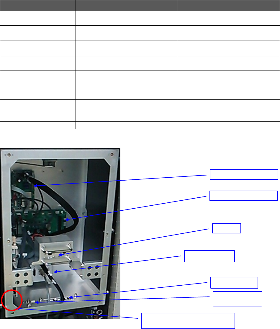
Fig.5-1 Inside View of NTG-420
NFB
Cable Clamp
Connector Board
Earth Point
(Chassis)
ANT I/F Circuit
PS I/F Circuit
Optical Fiber Cable inlet (See
below)

7ZPRR0001
14
Table 5-1 Signal Layout of each Terminal
Table 5-1 (1) P1
Pin No.
Pin Name
In/Out
Description
1
+48V
In
+48V
2
+48V RTN
In
+48V Return
3
GND
Ground
Table 5-1 (2) P2
Pin No.
Pin Name
In/Out
Description
1
MNT-TX-P
Out
Maintenance Port RS-422 output-P
2
MNT-TX-N
Out
Maintenance Port RS-422 output-N
3
MNT-RX-P
In
Maintenance Port RS-422 input-P
4
MNT-RX-N
In
Maintenance Port RS-422 input-N
5
MNT E
In/Out
Shield (Ground)
6
NC
-
Reserved
7
NC
-
Reserved
8
NC
-
Reserved
9
NC
-
Table 5-1 (3) P3
Pin No.
Pin Name
In/Out
Description
1
VD
Out
Radar Video Signal
2
VD_E
Out
Radar Video Signal Return
3
TRIG
Out
Radar Trigger Signal
4
TRIG_E
Out
Radar Trigger Signal Return
5
BP
Out
Antenna Bearing Pulse Signal
6
BPE
Out
Antenna Bearing Pulse Signal
7
BZ
Out
Bearing Reference Signal
8
BZE
Out
Bearing Reference Signal Return
9
NMEA_P
In/Out
Control/Monitoring Signal(RS-485)-P
10
NMEA_N
In/Out
Control/Monitoring Signal(RS-485)-N
11
NMEA_E
In/Out
Return
12
NC
-
Reserved
13
NC
-
Reserved
14
NC
-
Reserved
15
SHIELD
-
Table 5-1 (4) P4
Pin No.
Pin Name
In/Out
Description
1
SAF SW-
In
Antenna Safety Switch Return
2
SAF SW+
In
Antenna Safety Switch Signal
3
ΦZ
In
Antenna Bearing Pulse (ΦZ-Phase)
4
ΦZE
In
Return
5
ΦA
In
Antenna Bearing Pulse (ΦA-Phase)
6
ΦAE
In
Return
7
ΦB
In
Antenna Bearing Pulse (ΦB-Phase)
8
ΦAE
In
Return
9
NC
-
Reserved
10
NC
-
Reserved
11
NC
-
Reserved
7ZPRR0001
15
12
+12V ISO
Out
+12V Antenna Encoder Power
13
+12V RET
Out
Return
14
NC
-
Reserved
15
SHIELD
7ZPRR0001
16
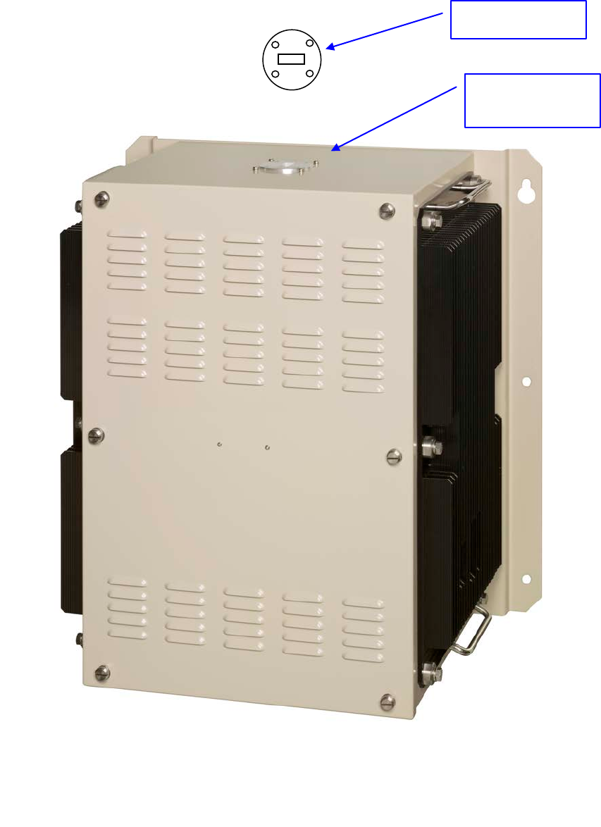
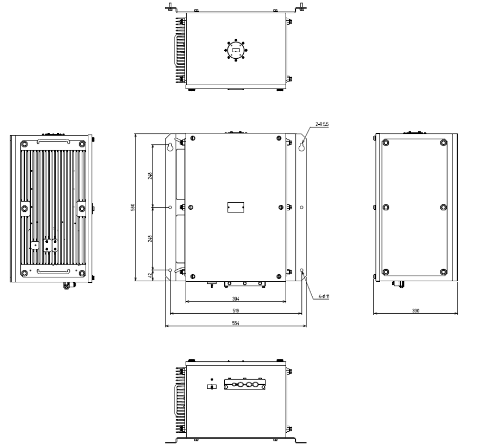
Fig. 5-2 Waveguide Flange (UG-51U) of NTG-420
Waveguide inlet
for NTG-420
(UG-51/U)
Flange
(M4 x 4)
7ZPRR0001
17
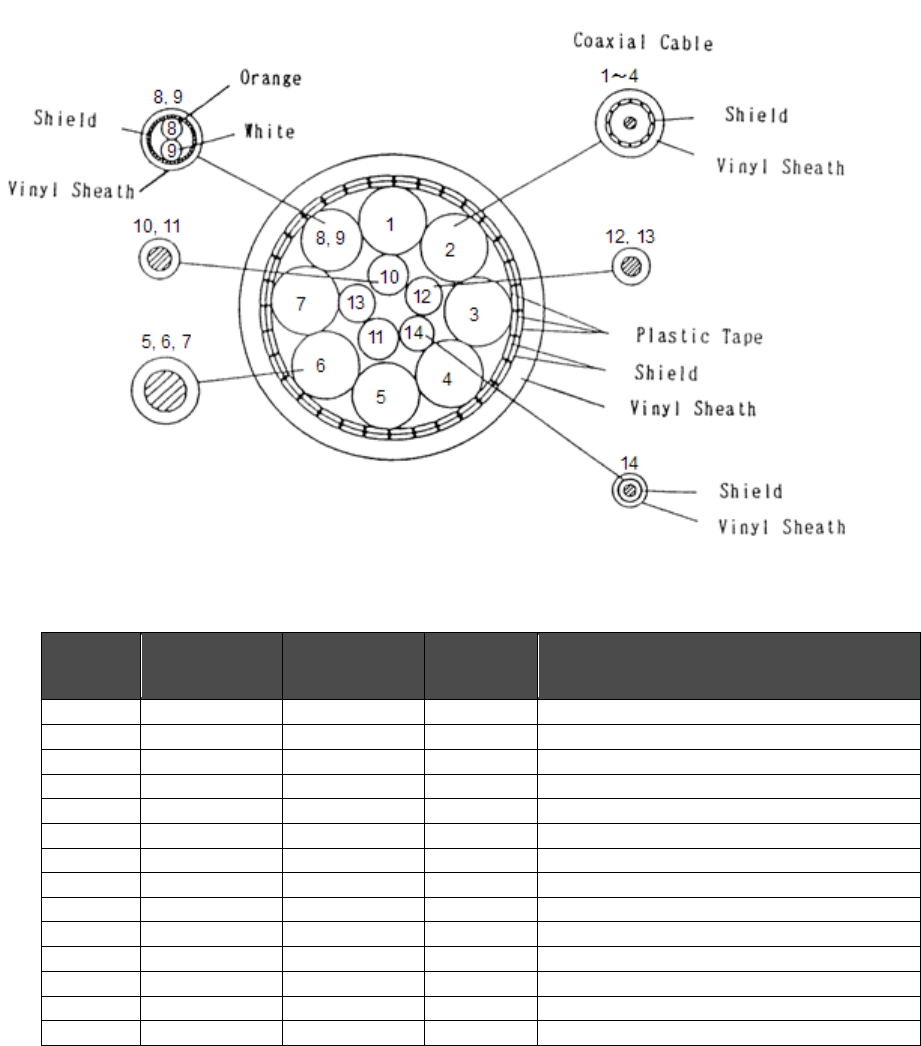
6. Installation Cable and Waveguide
6.1 CM14CXVBTBTV(2695110056)
This is composite cable of 14 wires with shielded coaxial cable. This cable is using
between Antenna and TRX. Also, equivalent cable can be used which is provided by
customer.
Fig.6-1 CM14CXVBTBTV(2695110056) Component
Table 6-1 CM14CXVBTBTV(2695110056) material
Core
(No.)
Cross Section
(m2) No. of wire / φ
Color Remarks
1
0.5
19 / 0.18
Black 1
Coaxial Cable
2
0.5
19 / 0.18
Black 2
Coaxial Cable
3
0.5
19 / 0.18
Black 3
Coaxial Cable
4
0.5
19 / 0.18
Black 4
Coaxial Cable
5
5.5
35 / 0.45
Yellow
6
5.5
35 / 0.45
Green
7
5.5
35 / 0.45
Brown
8
0.3
12 / 0.18
White
Twisted pair cable with Shield sheath white
9
0.3
12 / 0.18
Orange
10
2
37 / 0.26
Red
11
2
37 / 0.26
Blue
12
1.25
50 / 0.18
Black
13
1.25
50 / 0.18
Purple
14
0.5
1 / 0.18
Gray
Shield wire
Max. diameter: 23.0mm
7ZPRR0001
18
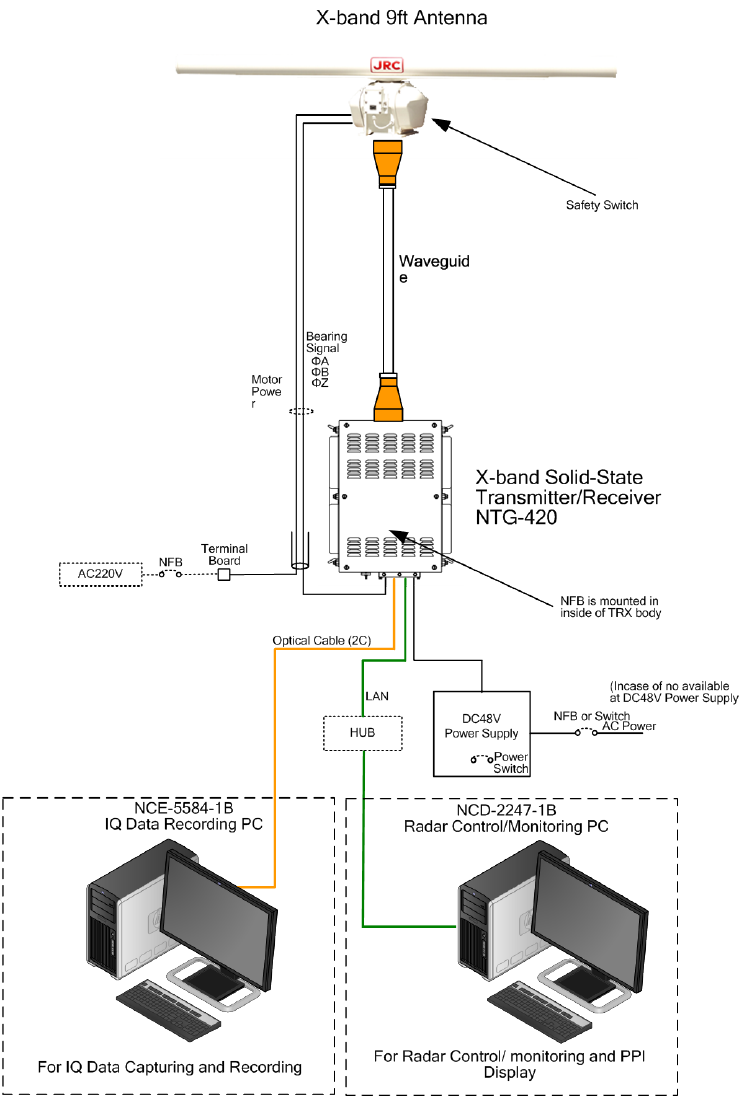
6.2 Waveguide and Cable Installation
Fig.6-2 Waveguide and Cable Installation Diagram for NTG-420 with peripheral equipment

7ZPRR0001
19
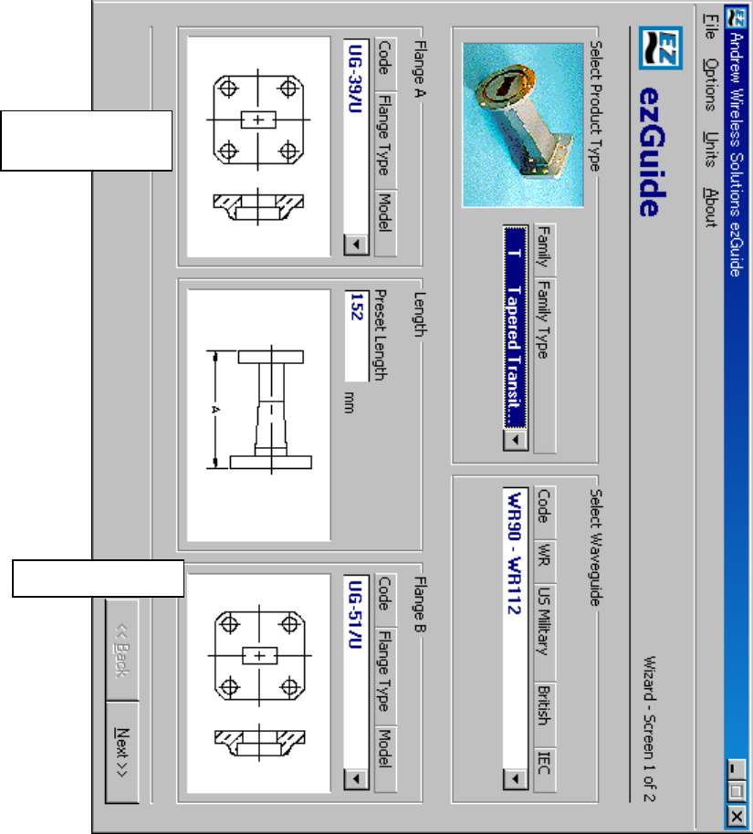
Table 6-2 Waveguide Materials List (for Example)
(No.)
WAVEGUIDE
Flange A
Flange B
Remarks
①
Tapered Transit Waveguide
(Flat): UG-51/U
(Flat) : UG-39/U
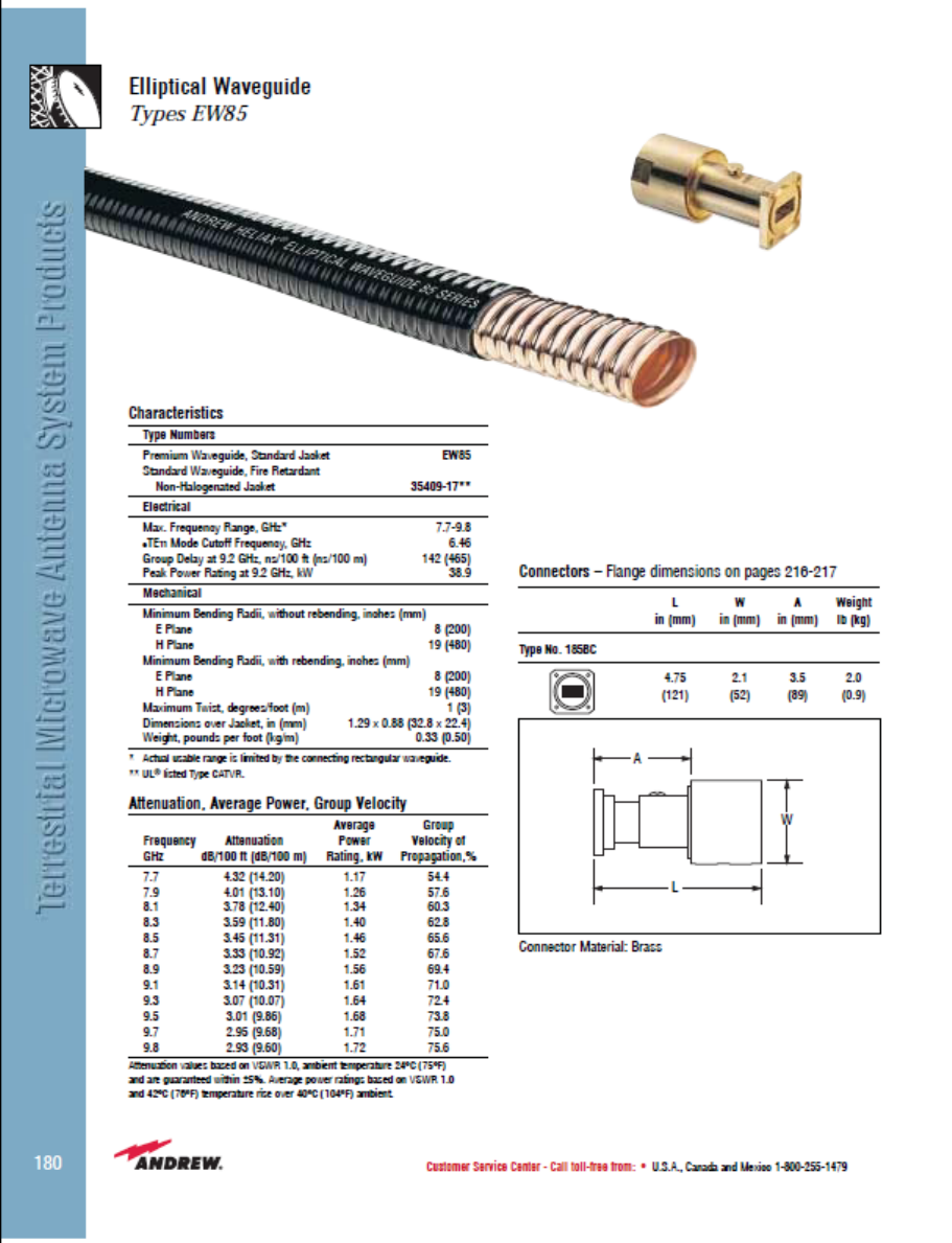
②
Flexible Waveguide
ANDREW
Model :Elliptical Waveguide
Type:EW85
Frequency Range :
7.7-9.8GHz
(Choke) : No.185BC
(Choke) : No.185BC
③
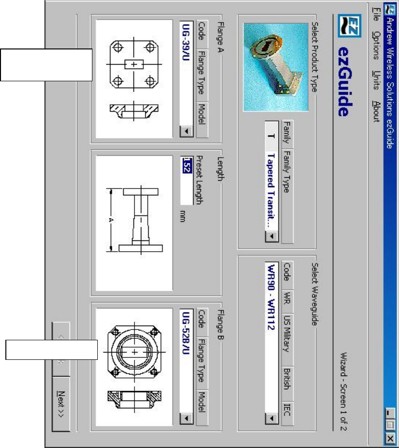
Tapered Transit Waveguide
(Flat): UG-39/U
(Choke) : UG-52B/U
Notes:
For detailed assembling method, please contact waveguide manufacturer(s) including
required special tools and materials

7ZPRR0001
20
APPENDIX
Drawing
OUTLINE DRAWING
X-BAND RADAR ANTENNA
NTG-420 X-BAND SOLID STATE TRANSMITTER-RECEIVER
BLOCK DIAGRAM
X-BAND RADAR ANTENNA
NTG-420 X-BAND SOLID STATE TRANSMITTER-RECEIVER
WIRING DIAGRAM
INTERCONNECTION FOR NTG-420 X-BAND SOLID STATE TRANSMITTER-RECEIVER
(REFERENCE)
WAVEGUIDE CATALOGUE
7ZPRR0001
21
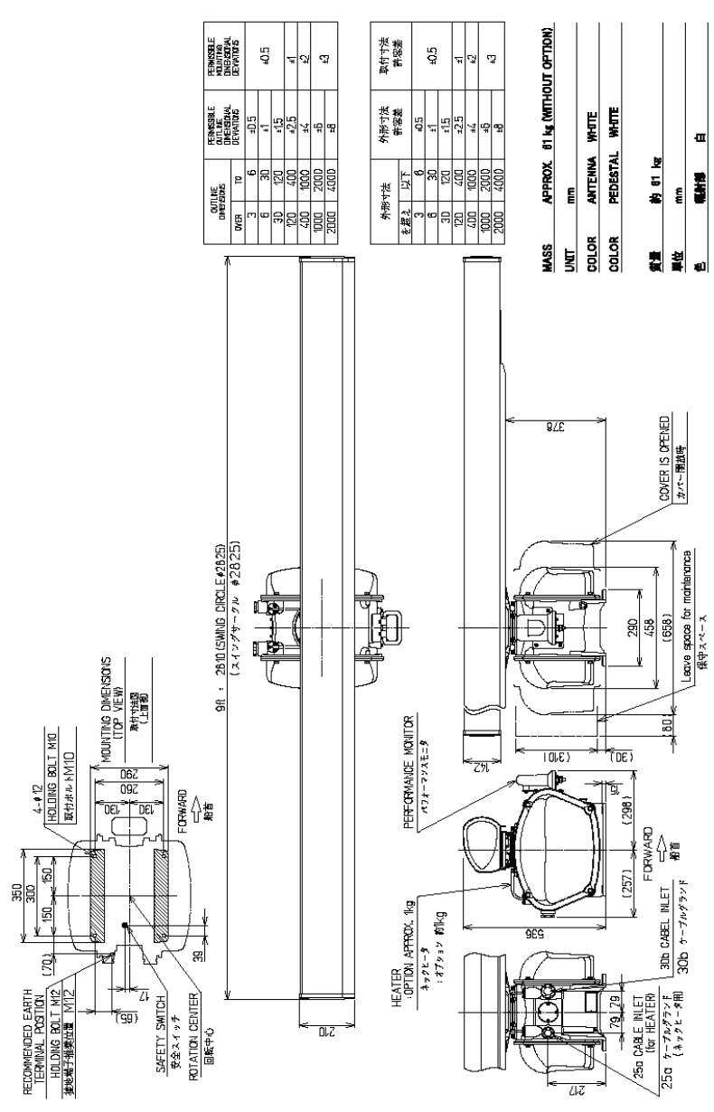
Outline Drawing of X-band Radar Antenna
Note: Performance Monitor does not included in this system.
7ZPRR0001
22
Outline Drawing of NTG-420 X-Band Solid State Transmitter-Receiver
7ZPRR0001
23
Block Diagram of X-band Radar Antenna
RF Inlet
Rotary
Joint
Bearing
Output(ΦA,ΦB,ΦZ)
Motor Enc order
Safety Switch
Status
Slotted Array Antenna
Turning Unit
Motor
Driver
Error
AC100/110 or 220/230V
50/60, 1Φ
7ZPRR0001
24
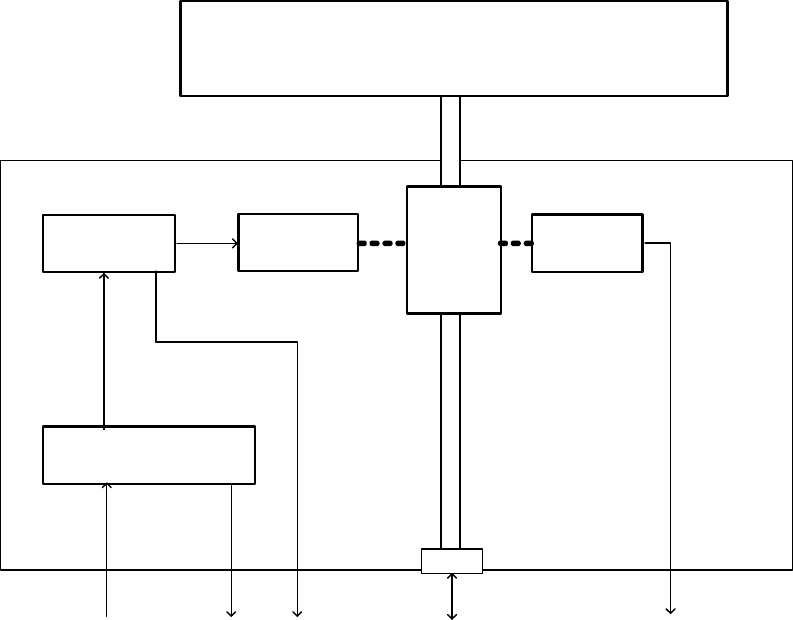
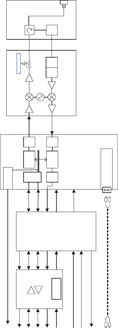
Block Diagram of NTG-420 X-Band Solid State Transmitter-Receiver
PS I/F Circuit
Bearing Signal out
RS-422 Cont
Trig. Video out
RS-485 Cont
DC48V in
ANT I/F Circuit
Bearing Signal in
Safety Switch
PS circuit
Buffer
Signal
Distribution
Circuit
Radar Data LAN
+12V ISO
Optical Fiber Cable
S/P Circuit
TRX Module
MPU
Waveform
Gen. D/A
A/D
Signal
Processor
D/A
MIX
LOC
OSC
LIM STC
ATT
TX MON
CIR
RF
BPF
SSPA
LNAAMP
AMP
RX IF
TX IF
RJ-45
Microwave
Component Circuit
RF Inlet
Transducer
Optical Communication
Board (AGM-741
daughter board )
LC Type connector
7ZPRR0001
25
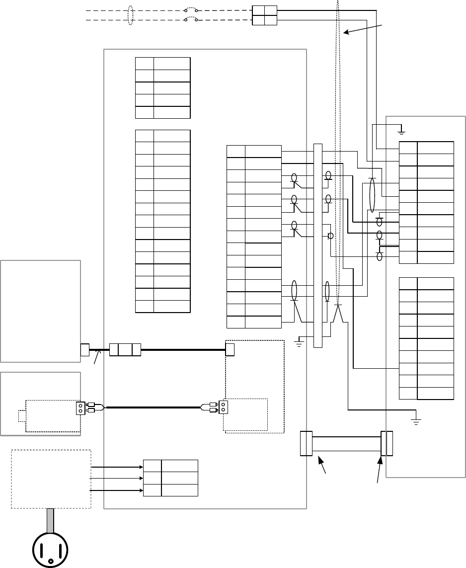
Interconnection for NTG-420 X-Band Solid State Transmitter-Receiver (Reference)
(Confirm the antenna motor power before installation)
1
NC
2
3
4
5
6
7
8
9
10
P4
1VD
2VD_E
3TRIG
4TRIG_E
5BP
6
7BZ
8
9
10
P3
11
12
13
14
JRC Standard
X-Band Radar
Antenna
Transmitter Receiver NTG-420
Radar
Control/Monitoring
PC display
NCD-2247-1B
For
Antenna Motor
1
2
+48V
3GND
+48V_RTN
DC+48V
1MNT_TX_N
2
3
4
5
P2
Waveguide
WRJ-9 or equivalent
Flange
UG-52B/U Flange
UG-51/U
MNT_TX_P
MNT_RX_P
MNT_RX_N
MNT_E
Cable
CM14CXVBTBTV
(2695110056)
1
2
1
2
Terminal Board
YEL
GRN
Provided by User
(5.5sq or more)
+48V_RTN
SEF SW-
SAF SW+
ΦZ
ΦZE
ΦA
ΦAE
ΦB
ΦBE
+12V ISO
+12V
RET
NC
NC
SHIELD
15
NC
NMEA_P
NMEA_N
BPE
BZE
P1
1
1
1
2
1
3
1
4
15 SHIELD
NMEA_E
NFB
RJ-45
RJ-45JJ
LAN
Radar Data
J2
NC
FG
48V DC PS
AC
(D-SUB 15P)
(JR13PK-3P(71))
(D-SUB 15S)
(D-SUB 9P)
Optical
Comm.
Board
(AGM-741)
Signal
Processor
Board
(CDC-
1469)
Optical Comm.
Board
(APX-741A-1)
Optical Fiber Cable
PCI-ex
IQ Data Recording PC
(NCE-5584-1B)
NC
LAN cable Cat.6a
1U
1
2V
1
3W
1
4
5
6
7
8
9E
10
TB103
+12V
ΦZE
ΦZ
ΦA
ΦB
SAF SW-
1
2
3
ORG
1PTI
2
3LVR
4
5
6
7
8
9VERR1
10
TB104
PMS
TXI
TXE
SAF SW+
E
E
PTE
FG
WHT
FG
NC
NC
NC
NC
NC
NC
NC
NC
NC
NC
9
8
12
13
BLK
PUR
FG
Relay
Terminal
1
2
4
5
6
7
8
9
10
11
12
16
AC100/110V or
220/230V
7ZPRR0001
26
Waveguide Catalogue
(1) Taper Waveguide
Antenna Side
Elliptical
Waveguide Side
7ZPRR0001
27
(2) Elliptical Waveguide
7ZPRR0001
28
(3)Taper Waveguide
Elliptical
Waveguide Side
Transmitter Side

7ZPRR0001
29
Maximum Permissible Exposure(MPE) Calculation
The MPE was calculated with the antenna used as the highest antenna gain which may be used.
Radiofrequency radiation exposure limits.(Frequency: 10MHz to 300GHz)
Limits for Occupational/Controlled Exposure(mW/cm2)=5.00
Limits for General Population/Uncontrolled Exposure(mW/cm2)=1.00
NTG-420 Performance characteristics
Antenna gain(dB)= 38 Assumed 22feet Slotted Array Antenna
Output Average
Power(W)= 4.6 (dBm)= 36.628
Frequency(MHz) = 9410
Cable Loss(dB) = 1 Assumed 10m Waveguide Lengh
Calculated EIRP mW) = 23054613 73.628
(dBm)
Power Density(SmW/cm2)=EIRP/4・π・r2
(r=cm)
EIRP Distance Distance Power Density (S)
mW cm Feet mW/cm2
23054612.7
1500 49.21
0.81539
23054612.7
1450 47.57
0.87259
23054612.7
1355 44.46
0.99924
General population
23054612.7
1350 44.29
1.00665
23054612.7
1300 42.65
1.08558
23054612.7
1250 41.01
1.17416
23054612.7
1200 39.37
1.27405
23054612.7
1150 37.73
1.38724
23054612.7
1100 36.09
1.51622
23054612.7
1050 34.45
1.66406
23054612.7
1000 32.81
1.83463
23054612.7
950 31.17
2.03283
23054612.7
900 29.53
2.26497
23054612.7
850 27.89
2.53928
23054612.7
800 26.25
2.86661
23054612.7
750 24.61
3.26156
23054612.7
700 22.97
3.74414
23054612.7
650 21.33
4.34232
23054612.7
610 20.01
4.93047
Occupational
23054612.7
550 18.04
6.06489
23054612.7
500 16.40
7.33851
23054612.7
450 14.76
9.05989
23054612.7
400 13.12
11.46643
7ZPRR0001
30
23054612.7
350 11.48
14.97656
23054612.7
300 9.84
20.38476
23054612.7
250 8.20
29.35405
23054612.7
200 6.56
45.86570
23054612.7
150 4.92
81.53903
23054612.7
100 3.28
183.46282
23054612.7
50 1.64
733.85127
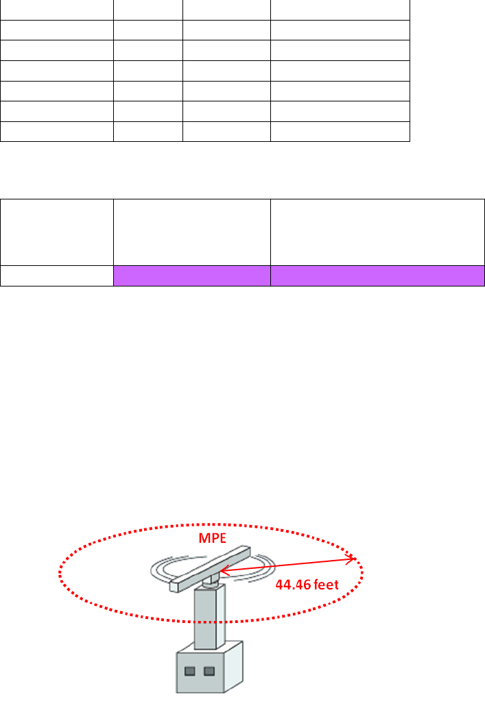
Conclusion:
Frequency
General population
Limit Minimum
Distance(feet)
Occupational Limit Minimum
Distance(feet)
10MHz-300GHz 44.46 20.01
The NTG-420 is radar system for operating at the land based services.
The radiating structure for the radar is typically mounted as following diagram.
The radar system will satisfy the requirements of RF exposure per rule.
Typical Installation of radar system

7ZPRR0001
31
FCC Caution
Changes or modifications not expressly approved by the party responsible for compliance could void
the user’s authority to operate the equipment.
This equipment generates, uses and can radiate radio frequency energy and, if not installed and
used in accordance with the instructions, may cause harmful interference to radio communications.
However, there is no guarantee that interference will not occur in a particular installation. If this
equipment does cause harmful interference to radio or television reception, which can be determined
by turning the equipment off and on, the user is encouraged to try to correct the interference by one or
more of the following measures:
1) Reorient or relocate the receiving antenna.
2) Increase the separation between the equipment and receiver.
3) Connect the equipment into an outlet on a circuit different from that to which the receiver is
connected.
4) Consult the dealer or an experienced radio/TV technician for help.
This device complies with Part 80 and Part 90 of the FCC rules.
Operation is subject to the following two conditions: (1) this device may not cause interference, and
(2) this device must accept any interference, including interference that may cause undesired
operation of the device.
IC (Indutry Canada)
This device complies with Industry Canada’s licence-exempt RSSs. Operation is subject to the
following two conditions:
(1) This device may not cause interference; and
(2) This device must accept any interference, including interference that may cause undesired
operation of the device.
Le présent appareil est conforme aux CNR d’Industrie Canada applicables aux appareils radio
exempts de licence.
L’exploitation est autorisée aux deux conditions suivantes :
1) l’appareil ne doit pas produire de brouillage;
2) l’utilisateur de l’appareil doit accepter tout brouillage radioélectrique subi, même si le brouillage est
susceptible d’en compromettre le fonctionnement.