Japan Radio NTG420 Solid State Transmitter-Receiver User Manual SSradarMaintenanceManual
Japan Radio Co Ltd. Solid State Transmitter-Receiver SSradarMaintenanceManual
Contents
- 1. Usera manual(Installation)
- 2. Users manual(Operation)
Users manual(Operation)

7ZPRR002
1
Operation Manual
for
THE NTG-420 SOLID STATE
TRANSMITTER-RECEIVER
Document No.7ZPRR0002
APR 2016

7ZPRR002
2
Revision Hsitory
Revision
Description
Issued
7ZPRR002
3
TABLE OF CONTENTS
SAFETY INFORMATION ................................................................................................4
1. Overview ...................................................................................................................10
2. Operation ..................................................................................................................11
2.1 How to start the system .....................................................................................11
2.2 How stop the System. ........................................................................................13
2.3 Radar Control Module (N_Cont. exe) Main Window ........................................13
2.4 Solid State Radar Signal Input Module(N_Solid.exe) ......................................22
2.4.1 Icon ...............................................................................................................22
2.4.2 Start-up the Screen .....................................................................................23
2.4.3 Main Menu ....................................................................................................23
2.4.3.1 File ..........................................................................................................23
2.4.3.2 View ........................................................................................................24
2.4.3.3 Help ........................................................................................................24
2.4.4 Tree Menu and Functional Description ..................................................25
2.4.4.1 Radar Image ..........................................................................................26
2.4.4.2 Input Image ............................................................................................37
2.4.4.3 Failure history .......................................................................................43
2.4.4.4 Simulation ..............................................................................................43
2.4.4.5 Sweep Tag .............................................................................................44
2.5.5 Admin Menu .................................................................................................47
2.5.5.1 Radar Image ..........................................................................................47
2.5.5.2 On Error Reboot ....................................................................................48
2.5.5.3 Admin Password ...................................................................................48
2.5.5.4 Process ..................................................................................................48
2.5.5.5 Common Memory ..................................................................................49
2.5.5.6. Debug ....................................................................................................49
2.6 Startup parameter ..............................................................................................49
3. Specification ............................................................................................................50
FCC Caution .................................................................................................................52
IC (Indutry Canada)......................................................................................................52
7ZPRR002
4
SAFETY INFORMATION
To prevent harm to those who use this product or other people and damages to
property, safety precautions to be followed are described as follows.
★ The degrees of harm and damages caused by misuse with neglecting indications
are classified and described as follows.
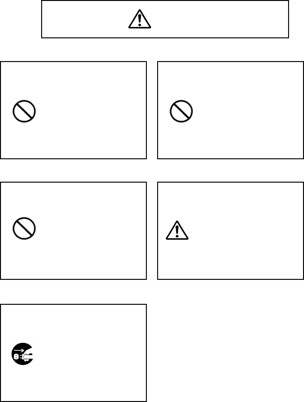
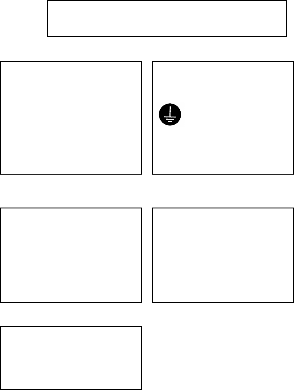
★ Kinds of precautions to be followed are classified and described with the following icons.
(A few examples of icons are as follows.)
This icon is to call attentions.
This icon is to prohibit some actions
This icon is to force some actions.
This indication means "Hazard can cause injury or only physical
damages."
WARNING
DANGER
This indication means "Hazard can cause severe injury or
7ZPRR002
5
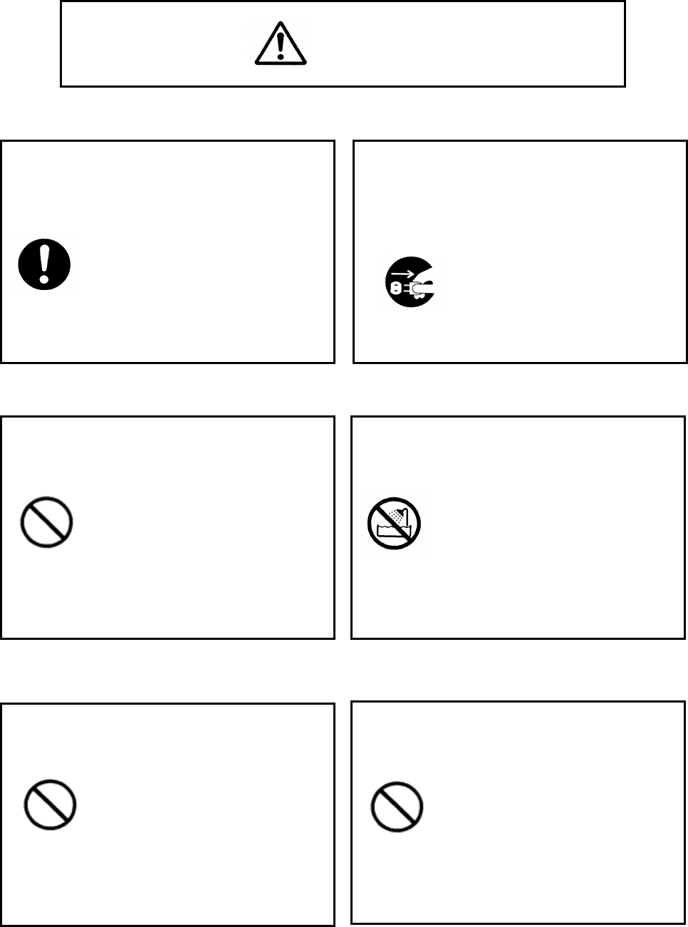
DANGER
Plug in completely
Incomplete plugging may
generate heat to cause a shock
or a fire.
In case of malfunctions or abnormal
conditions (smoke, foul odor, sound,
etc.), turn the power off and turn off
the breaker of the power distributor.
Turn the power off and
consult with our
company.
Do not repair the device by
yourself because it is
dangerous.
Unplug
Do not put the device on unstable
places(a shaky stand, tilted place,
etc.).
Dropping or falling down of the
device may cause injury.
Prohibition
Do not wet or water the device.
Wetting the device may cause a
shock or a fire.
Do not wet
Do not put things (containers with
liquid, flower pots, etc.) or creatures
on the device.
Do not put li
quid such as water,
metals or inflammable objects inside
the device.
Prohibition Prohibition
Entering of liquid or
ex
crement may cause a
shock or a fire.
★
In case of entering,
unplug from the outlet and
consult with our company.
Entering may cause a shock
or a fire.
In case of entering, unplug
from the outlet and consult
with our company.
7ZPRR002
6
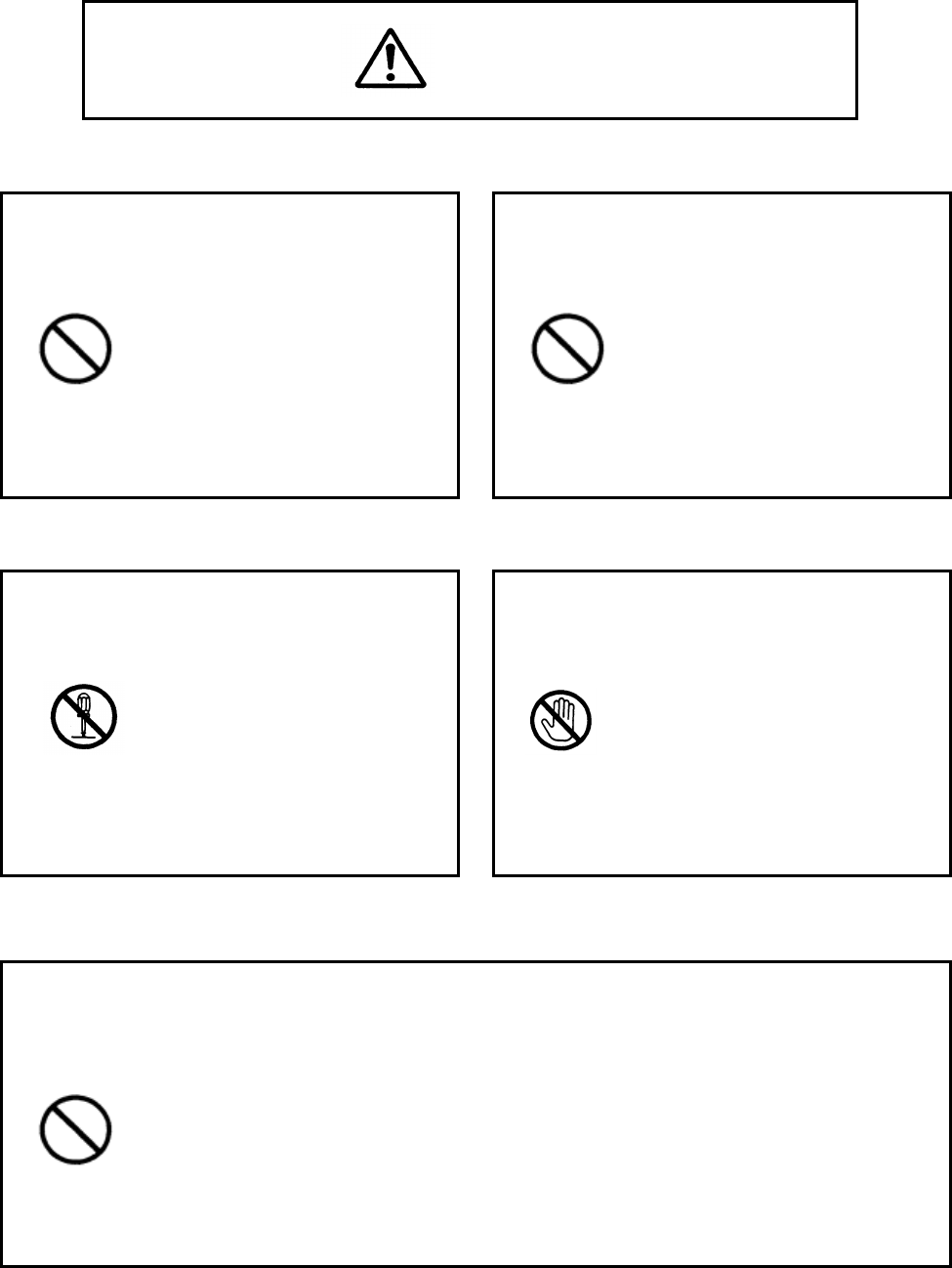
Do not drop or bump the device.
Physical shock may cause a s
hock or a fire.
Do not use the device under a voltage
other than the indicated power-supply
voltage.
Malfunction may occur to
cause a shock or a fire.
Prohibition
Do not remove the back lid, the cabinet or
the cover, or do not modify the device.
Consult with our company for
internal inspection and repair.
Do not decompose
When thunder has started, do not touch
the power cables, the signal cables and
the device.
Touching will cause a
shock
Do not touch
DANGER
Prohibition
Do not damage the power cord or the plug.
Damaging, processing, loading, heating, bending and twisting
forcedly or pulling may deteriorate insulation of coating, expose
cores or break the cord to cause a shock or a fire.
★ In the case of damages, unplug from the outlet and ask our company
Prohibition
7ZPRR002
7
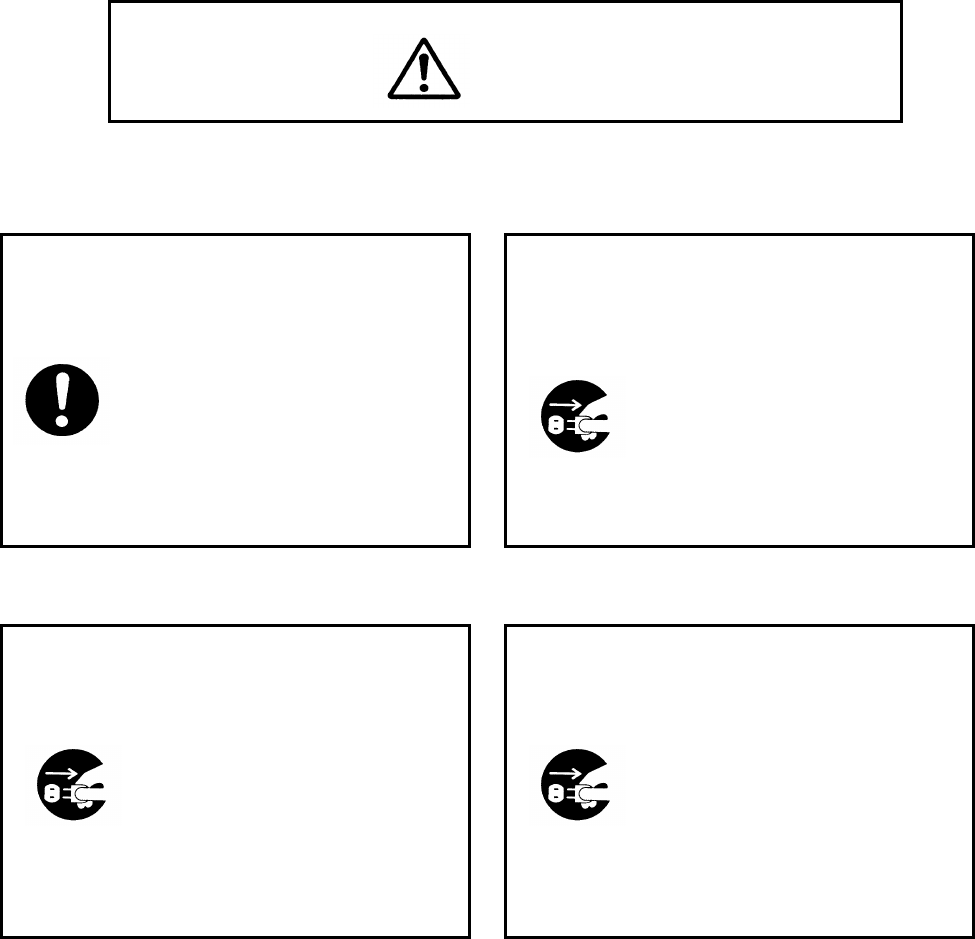
WARNINGS
Carry the CRT monitor by more than
one people since the monitor is
heavy.
Stumbling, etc. may cause injury.
Disconnect the plug and the connection
lines when moving the device.
Damage of cords may cause a
shock or a fire.
Unplug
Unplug with holding the plug.
Damage of cords may cause a
shock or a fire.
Unplug from the outlet for safety when
maintaining
A shock may be caused.
Unplug
Unplug
7ZPRR002
8
WARNINGS
Do not unplug with wet hands
A shock may be caused.
Do not block the ventilation holes of
the cabinet.
Heating up internally may
cause malfunction or a fire.
Pay attention to the following:
★Do not turn over, lay down or
set upside down the device
Prohibition
Prohibition
Do not put the device where much moisture
or dust exists, and greasy fumes or steam is
generated.
Putting the devic
e on a
cooking table or near a
heater may cause a shock or a
fire.
Ask our company for internal
inspection and cleaning periodically.
Without cleaning for a long time,
dust gathered inside the device
may cause malfunction or a fire.
Prohibition
Unplug from the outlet when not
using for a long time.
Dust gathered on the plug may
cause a fire or a shock.
Unplug
7ZPRR002
9
Do not put othe
r devices (a TV, a
display device, etc.) or magnetized
objects near the CRT monitor.
Installing the CRT monitor near those
may have an
effect on the screen
(disturbing colors or swaying the
screen).
★
Move the device seemed to effect
away as possible. In case the
phenomenon does not stop even so,
Ground the earth wire of the
plug.
A shock may be caused
without grounding the earth
wire.
Furthermore, poor reception
f
or TV's, radios, etc. may
CAUTIONS
Do not use the device in a dark place at
close range for a long time. Using the device
in a dark place at close range for long time
may weary eyes or weaken eyesight.
★Use the device at a distance of 40
or 50 cm in a bright
place where
newspaper can read easily. Take a
rest for eyes every 30 minutes.
Do not contact the cabinet with rubber
or plastic products for a long time.
The quality of the cabinet may alter or
the coating may come off.
Do not put the device in direct
sunshine or in the heat of heating
apparatus.
Heat may cause deformation of the cabinet
or malfunction of parts.
7ZPRR002
10
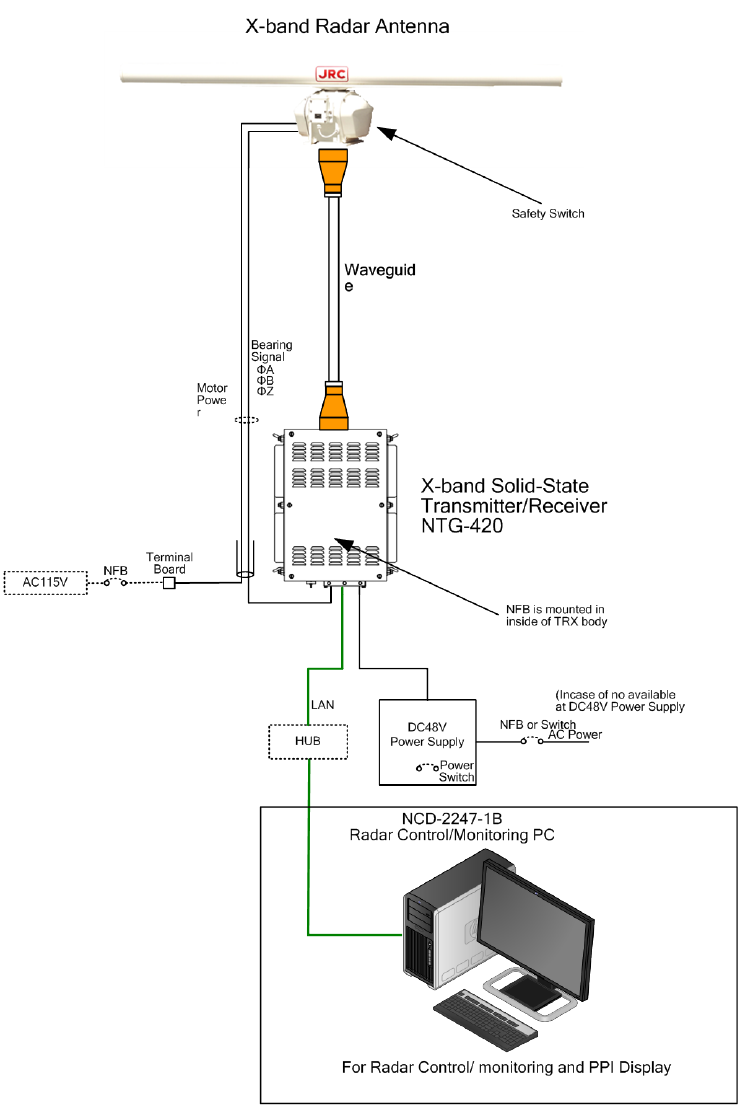
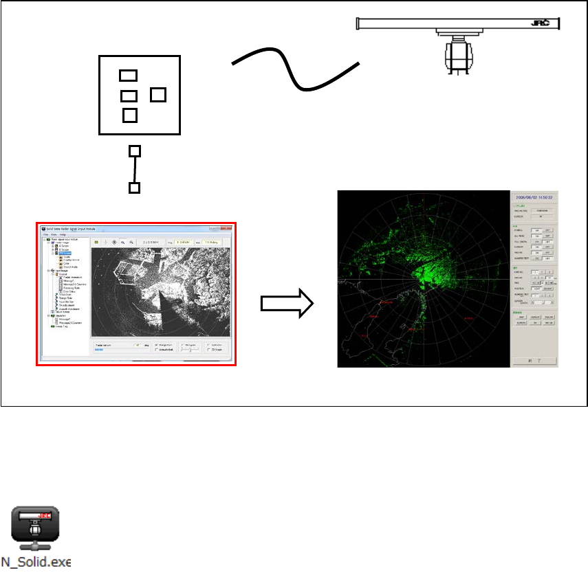
1. Overview
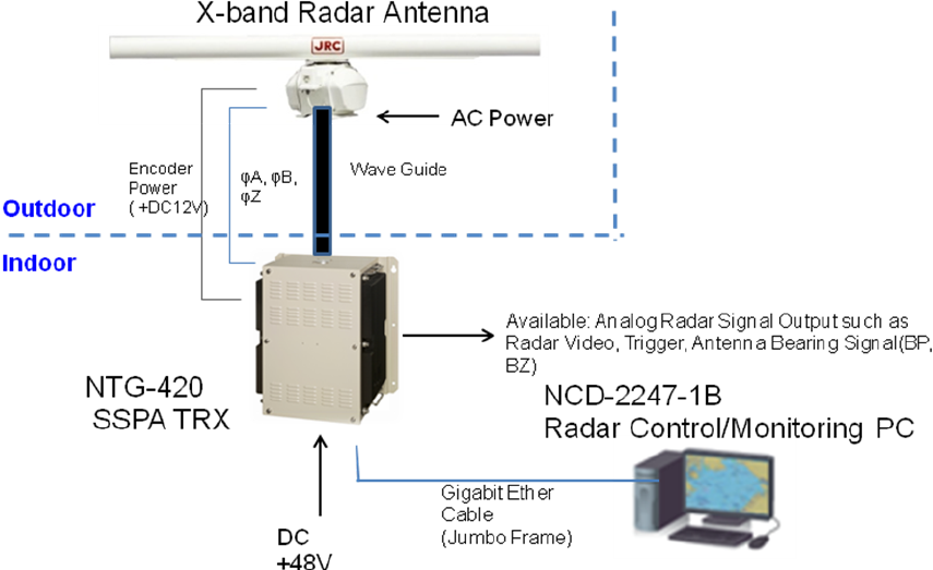
This manual describes operation function of the NTG-420 Solid State Transmitter-Receiver that is
used for the land based radar surveillance system.
Figure-1.1 shows total system illustration diagram of the NTG-420 and peripheral equipments.
And Figure-1.2 shows functional data flow of the NTG-420.
Figure-1.1 Total System Illustration Diagram of the Radar System.
7ZPRR002
11
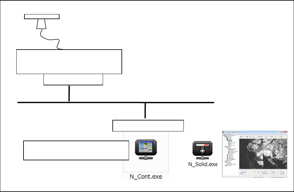
Fig. 1.2 Functional Data flow of the Radar System
2. Operation
2.1 How to start the system
1) Turn on the DC48V Power Supply by it’s switch or attached NFB.
SSPA TRX
NTG-420
(Signal Processor CDC-1469)
TCP Server
TCP Client
X-band Radar Antenna
Radar Control/Monitoring PC
NCD-2247-1B
UDP (TCP/IP)
Image Capture
7ZPRR002
12
2) Turn on the power switch on the NCD-2247-1B
3) Open the main menu Window (CDC-1469 control module by LAN (NMEA).
See paragraph 2.3
4) Confirm the no error indication on main menu.
5) Turn on Antenna motor NFB. (Before turn on, It checks that there are no people near the
antenna.
6) Click the Transmit ON button on the main menu
7) Echo will appear on the “Solid State radar Signal Input Module window”. See paragraph 2.4
7ZPRR002
13
2.2 How stop the System.
1) Stop the system by reverse procedure of the how to start.
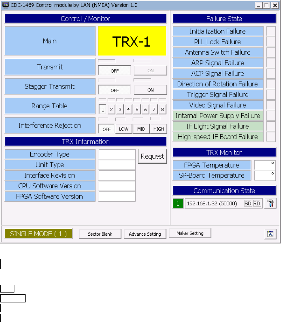
2.3 Radar Control Module (N_Cont. exe) Main Window
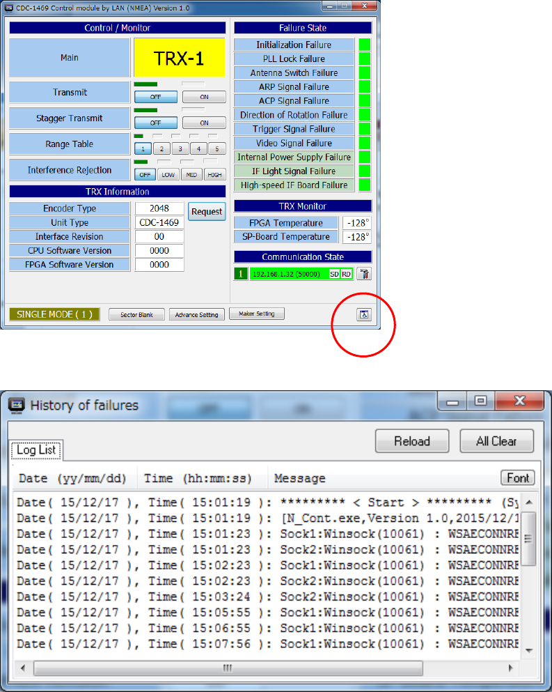
The following indication will be displayed when NTG-420 and NCD-2247-1B are connected normally.
SIGNAL MODE(1) window menu
Control/Monitor
Main :TRX-1 displayed
Transmit : OFF: Transition turned off, ON: Transmission turned on
Stagger Transmit : OFF: Stagger Transition turned off, ON: Stagger Transmission turned on
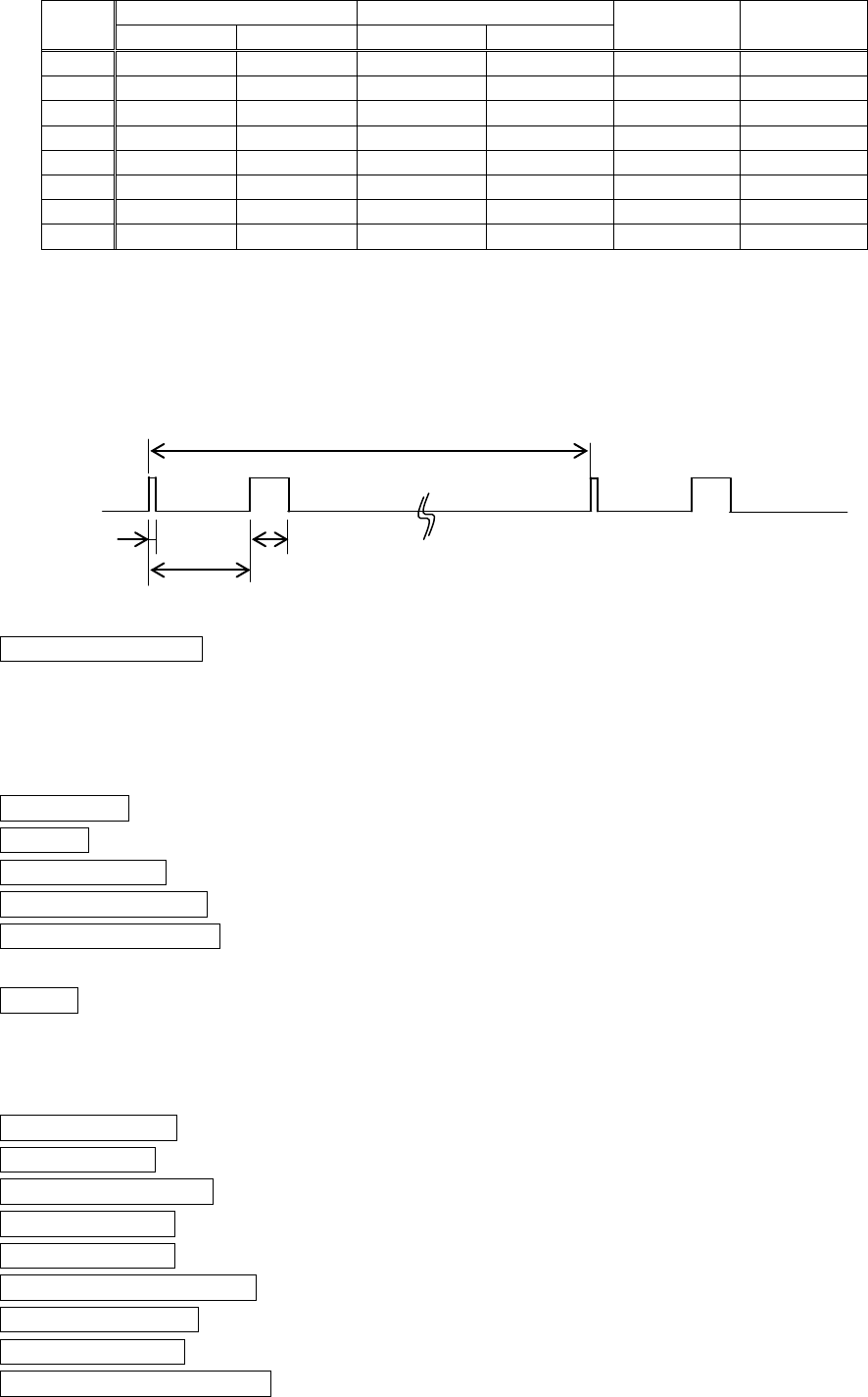
Range Table : Selects Range Table shown as table below.
7ZPRR002
14
Table
No.
No1. Transmit
No.2 Transmit
PRF
(Hz)
Tm1
(us)
PW(us)
FM(MHz)
PW(us)
FM(MHz)
1
0.07
0
2.8
30
2280
97.52
2
0.15
0
4.6
30
2280
97.52
3
0.3
0
9.1
20
2280
97.52
4
0.15
0
18.3
30
1280
97.52
5
0.15
0
28.0
30
640
97.52
6
0.3
0
9.1
30
1864
97.52
7
0.6
0
9.1
30
1280
97.52
8
0.07
0
2.8
30
4100
97.52
Remarks;
PW: Pulse Width, FM: Frequency Modulation range,
PRF: Pulse Repetition Frequency,
TM1: Time interval between No.1 and No.2 transmission
Interference Rejection: Adjusts the interference rejection strength level
Off / Low / Middle / High
TRX Information
Encoder Type : 2048 (Encoder pulse numbers)
Unit Type : CDC-1469 (Signal Processor Model)
Interface Revision : 00
CPU Software Version : 0000
FPGA Software Version : 0000
Request : Updated when click this button
Failure State
Initialization Failure : FPGA initialization failure.
PLL Lock Failure : PLL lock faiture on the master clock of signal processor.
Antenna Switch Failure : Antenna Safety Switch turned ON.
ARP Signal Failure : Lacked the Antenna encoder reference pulse.
ACP Signal Failure : Lacked the Antenna encoder pulse.
Direction of Rotation Failure : Antenna is reverse rotation.
Trigger Signal Failure : Lacked the Radar trigger signal.
Video Signal Failure : Lacked the radar video signal during specified period.
Internal Power Supply Failure : TRX internal power supply became abnormal condition. TRX.
No.1 Transmit No.2 Transmit
PW PW
PRF
Tm1
FM: Frequency Modulation Shift
FM
7ZPRR002
15
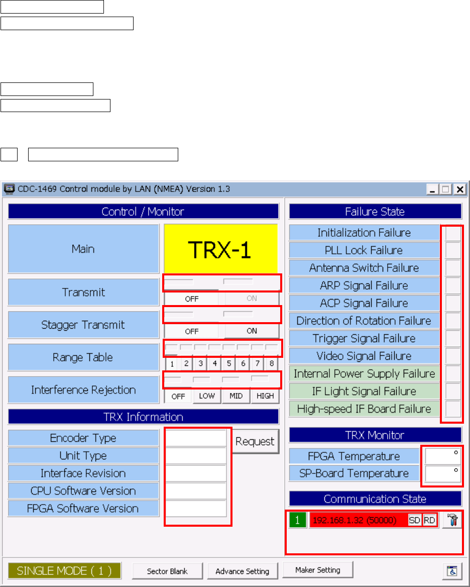
IF Light Signal Failure : IF Optical Fiber signal Lost.
High-speed IF Board Failure : AVAL Optical Board is Failure.
TRX Monitor
FPGA Temperature : xxx°shows temperature
SP-Board Temperature : xxx°shows temperature
Communication State
1 192.168.1.32(50000) SD RD : Green :Normal condition, Red :Abnormal(See below)
7ZPRR002
16
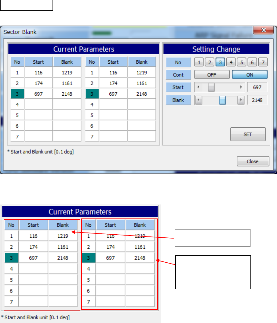
Sector Blank window menu
Transmission Sector blanking angle can be presentable.
This radar system has 7(seven) sector blanking area which are presentable individually.
Input preset angle data
Actual preset angle
data(response from
TRX)
7ZPRR002
17
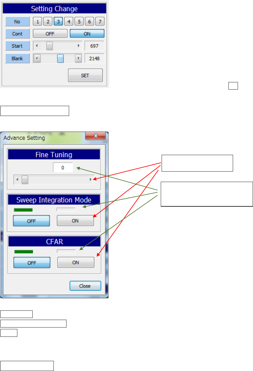
The blanking data of an input is reflected by pushing a SET button.
Advanced Setting window menu
Fine Tuning : Reserved Function.
Sweep Integration Mode : ON or OFF (Reduce the Noise and Clutter echo)
CFAR : ON or OFF (Constant False Alarm Rate)
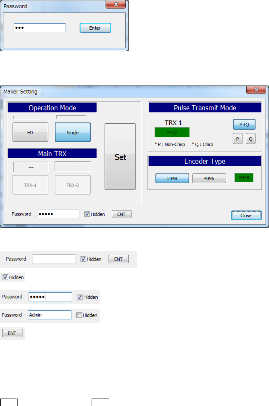
Maker Setting window menu
This menu is presented by manufacture’s factory, so that please do not change recklessly..
Input data
Actual preset angle
data(response from TRX)
7ZPRR002
18
A password input is required when open the maker setting window.
Initial password is “admin”.
Setting of Password
The mask of the inputted password is canceled temporarily.
Click the ENT button and password will be memorized.
* When a blank is set up, attestation with a password is not carried out.
* It is enciphered and the inputted password is saved at an initialization file.
Operation Mode
FD : Not used
Single This system can be used Single only
7ZPRR002
19
Main TRX
Not used in this system.
Pulse Transmit Mode (Default is P+Q)
TRX-1 : P+Q (Indicate current transmission mode)
P+Q : Select Both P(non-chirp) and Q(chirp) transmission pulse
P : Select P pulse only
Q : Select Q pulse only
Encoder Type
2048 : Select antenna encoder 2048 pulse type
4096 : Select antenna encoder 4096 pulse type
2048 Green indication (Indicate current selected encoder type)
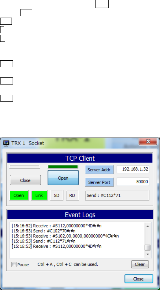
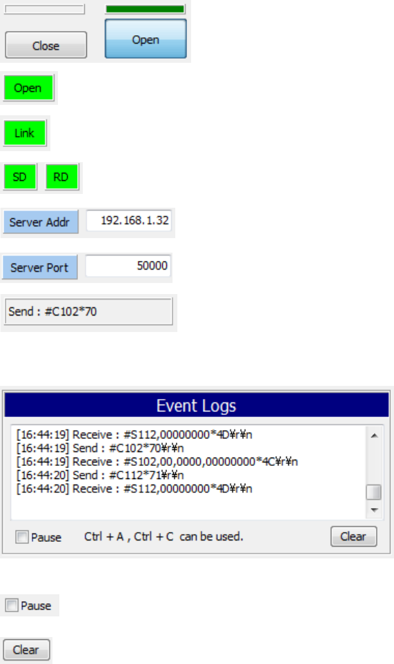
Communication Preset Window
7ZPRR002
20
TCP Client
Open/Close a socket
Socket open state
Socket connection state
Flashing at sending and receiveing
Server IP address
Server port number
Indicate the communication event
Communication Event Log indication
Update of the log of a communication event is stopped.
The log of a communication event is cleared.
※ If you want to save the contents that are displayed in the file, copy it to the clipboard using such
as Ctrl + A and Ctrl + C, please save the file using Memo-pad etc.
7ZPRR002
21
History of Failures Log Window indication
Click the here
The history of failure window displayed.
7ZPRR002
22
2.4 Solid State Radar Signal Input Module(N_Solid.exe)
This module captures in a radar picture using an UDP socket (TCP/IP) from a solid-state TRX signal
processing circuit (CDC-1469). The captured radar picture is provided through a shared memory to
other applications. Also, Radar PPI image can be monitored using this module.
2.4.1 Icon
Capture module
N_Solid.exe
Display Application
VTS,ATC etc
Radar Signal
SSTRX S/P Circuit
CDC-1469
UDP
(TCP/IP)
Shared Momory
7ZPRR002
23
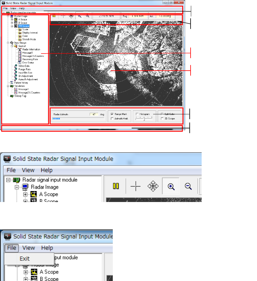
2.4.2 Start-up the Screen
2.4.3 Main Menu
2.4.3.1 File
(1) Exit
Exit the Application
Note: When this application is started according to the launcher process (Stater2.exe) of
exclusive use, a window is closed and it operates in the background.
Main Menu
Tool Bar
Tree Menu
Radar Image
Input Panel
Status Bar
7ZPRR002
24
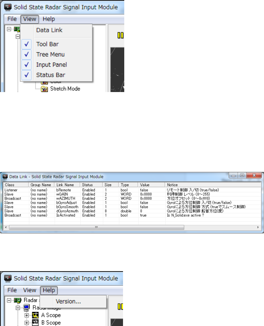
2.4.3.2 View
Data Link:Display the Data Link Screen
Tool Bar:Display on/off of the tool bar
Tree Menu:Display on/off of the tree menu
Input Panel:Display on/off the input panel
Status Bar:Display on/off of the status bar
(1) Data Link screen
Other applications and the state of InterProcess communication are displayed.
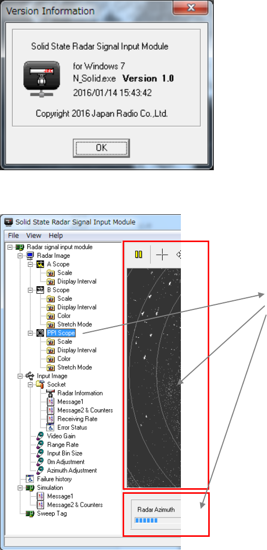
2.4.3.3 Help
(1) Version
7ZPRR002
25
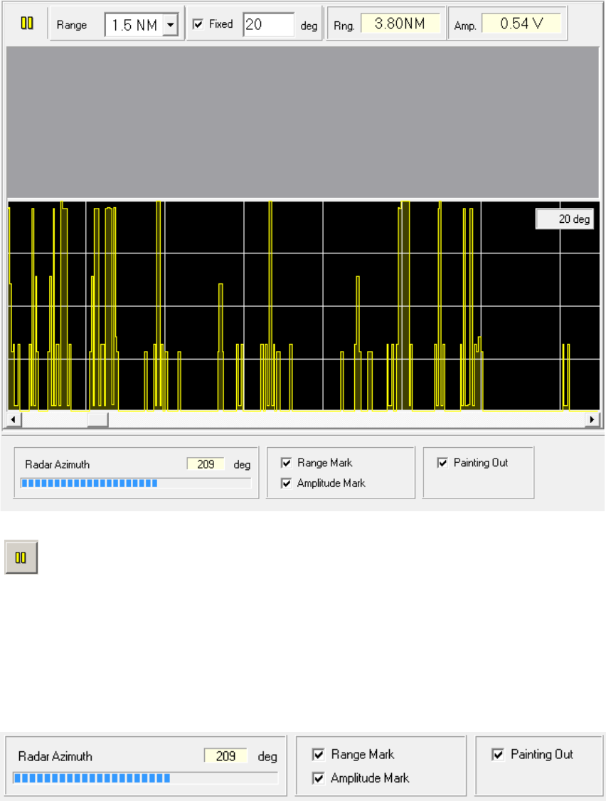
2.4.4 Tree Menu and Functional Description
A function name is displayed in tree form. When a function name is selected, a related
picture and a related input panel are displayed.
The picture and input panel
relevant to the selected
function name are
di l d
7ZPRR002
26
2.4.4.1 Radar Image
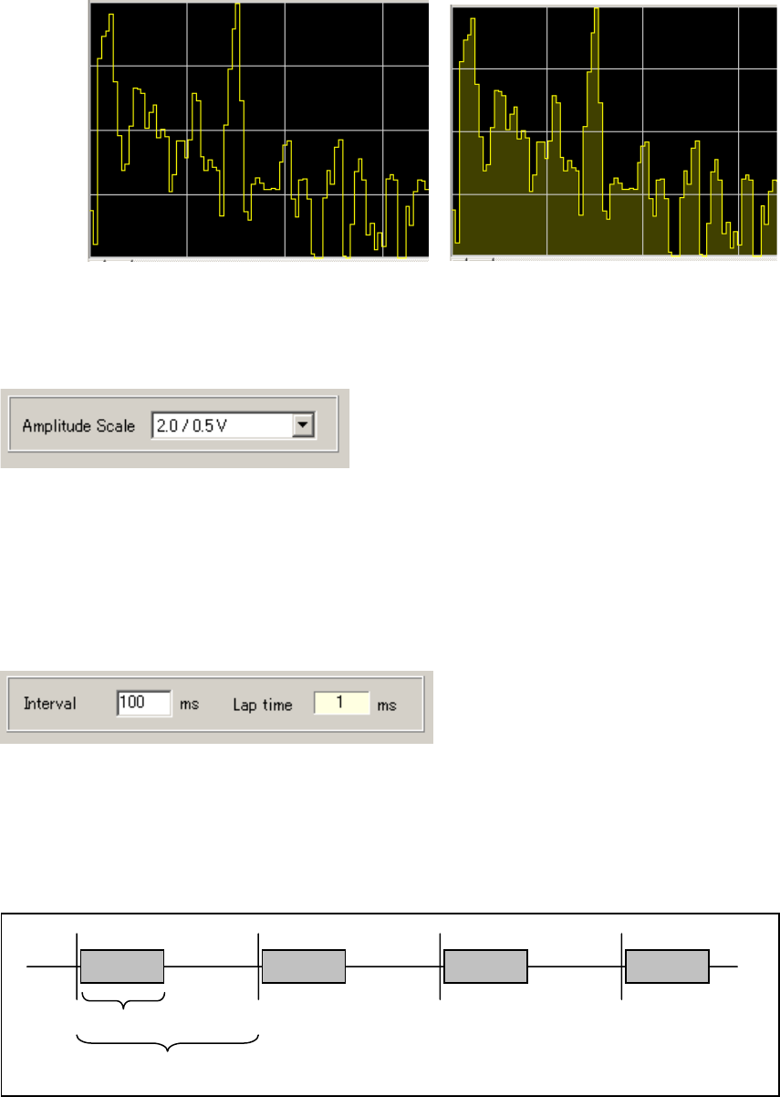
(1) A Scope
: Image update is stopped when this switch turned ON.
Range: Selects radar display range.
0.5 NM, 0.75 NM, 1.5 NM, 3 NM, 6 NM, 12 NM, 24 NM, 48 NM, 96 NM, 192 NM,
Fixed: Fixed the display azimuth.
Rng.: Displays distance of cursor position.
Amp.: Displays echo level(amplitude) of the cursor position (reference value).
Input Panel
Radar Azimuth: Displays the radar antenna azimuth angle.
Range Mark: Selects display on/off of the Range Marker.
Amplitude Mark: Selects display on/off of the amplitude marker.
Paint Out: : Selects painting out on/off.
7ZPRR002
27
Painting out off Painting out on
(Please select according to CPU load)
1) Scale
Amplitude Scale: Selects amplitude scale.(Scale/Marker Interval)
・ 0.5 / 0.1 V
・ 1.0 / 0.2 V
・ 2.0 / 0.5 V
・ 5.0 / 1.0 V
(Amplitude(level) is reference value).
2) Display Interval
Interval: Presets the update interval of radar picture. (Preset range:10~1000mS)
Lap time: Displays the radar picture depiction lap time.
If an updating cycle is shortened, the load of CPU will increase.
(Please preset according to CPU load)
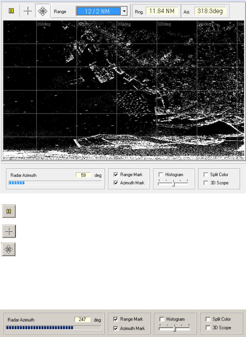
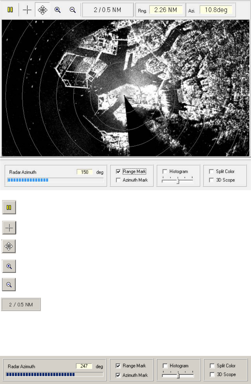
(2) B-Scope
Depiction time
Interval
7ZPRR002
28
: Image update is stopped when this switch turned ON.
: Shows cursor position in the picture.
: Moves picture position.
Range: Selects radar display range.
Rng.: Displays distance of cursor position.
Azi.: Displays azimuth angle of cursor position.
Input Panel
Radar Azimuth : Displays the radar antenna azimuth angle.
Range Mark : Selects display on/off of the Range Marker.
Azimuth Mark : Selects display on/off of the azimuth marker.
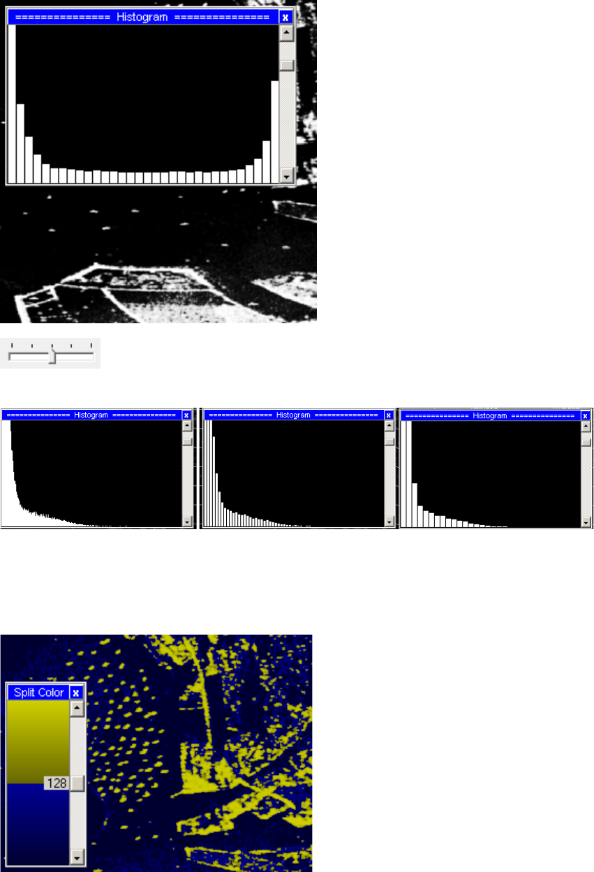
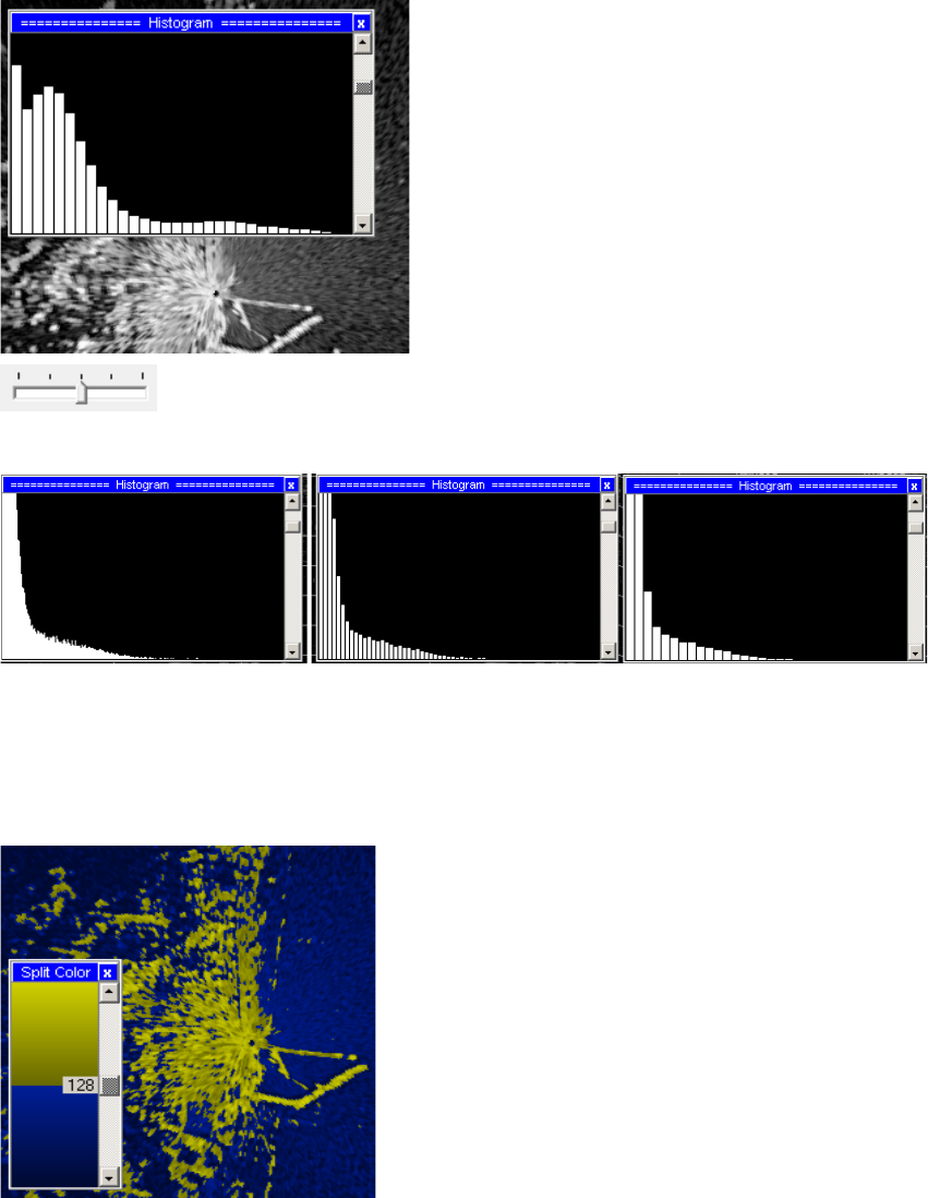
Histogram : Selects display on/off of the histogram.
7ZPRR002
29
: Selects the histogram section width.
1 x 256, 4 x 64, 8 x 32, 16 x 16, 32 x 8
1 x 256 4 x 64 8 x 32
Split Color: Display on/off of the function to classify a radar picture by color to two gradation is
changed.
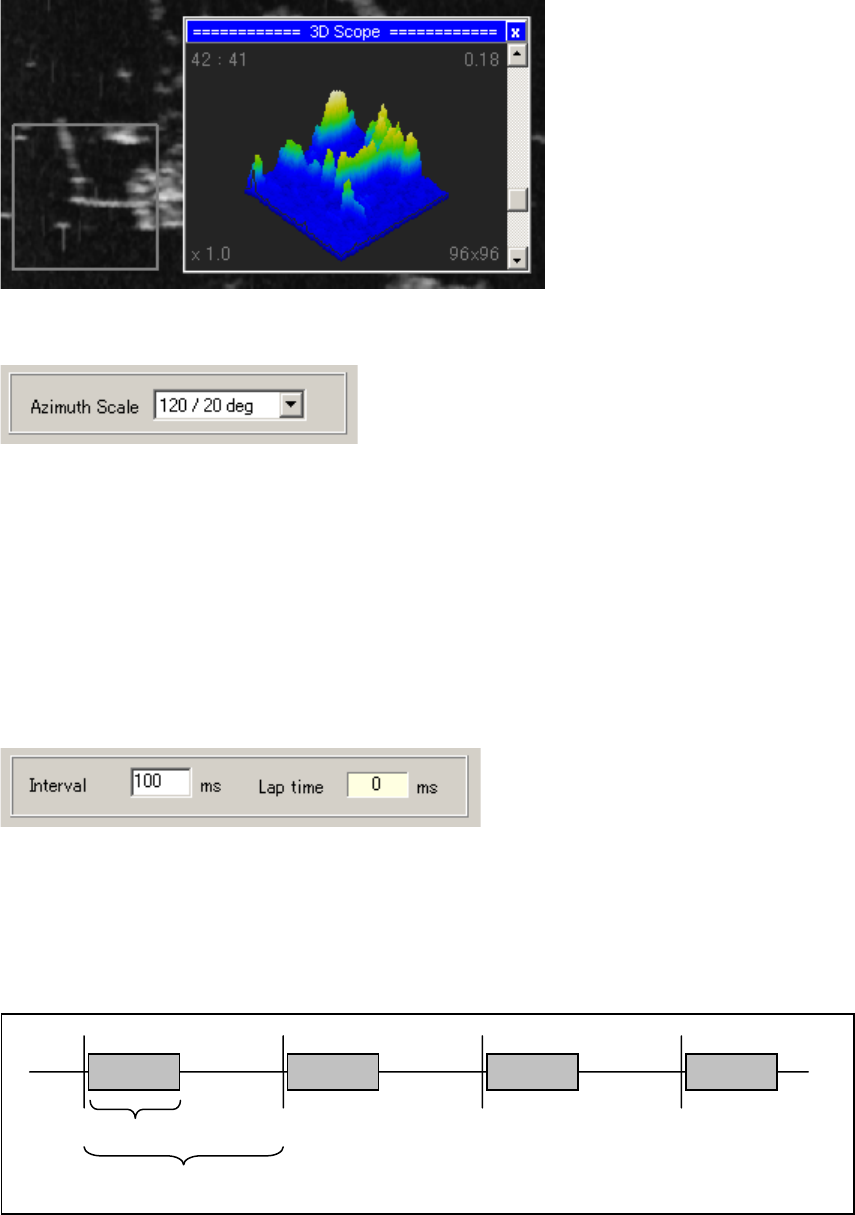
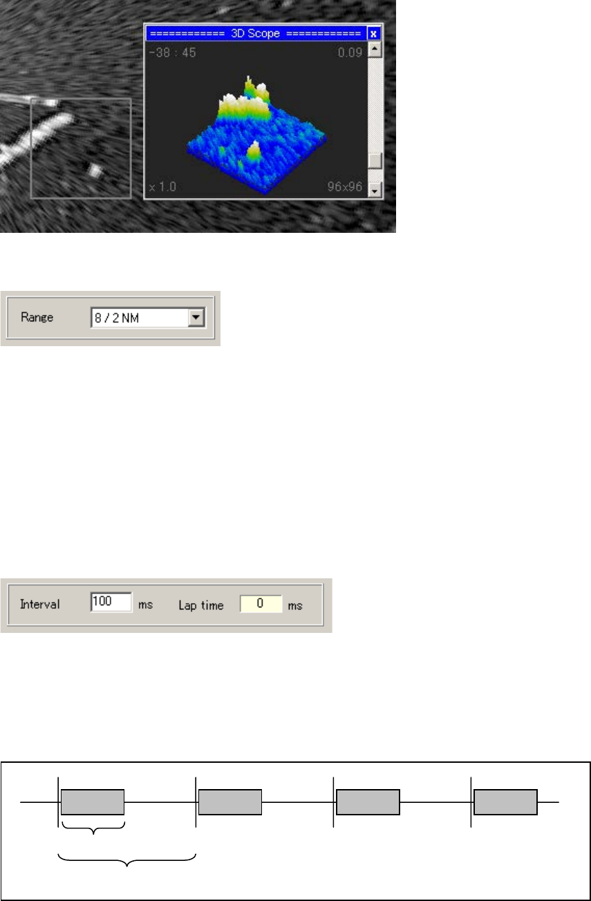
3D Scope:Selects the 3D display on/off.
7ZPRR002
30
1) Scale
Azimuth Scale: Selects azimuth scale. (Scale/Marker interval)
・ 30 / 5 deg
・ 60 / 10 deg
・ 90 / 15 deg
・120 / 20 deg
・180 / 30 deg
・270 / 45 deg
・360 / 60 deg
2) Display Interval
Interval: Presets the update interval of radar picture. (Preset range:10~1000mS)
Lap time: Displays the radar picture depiction lap time.
If an updating cycle is shortened, the load of CPU will increase.
(Please preset according to CPU load)
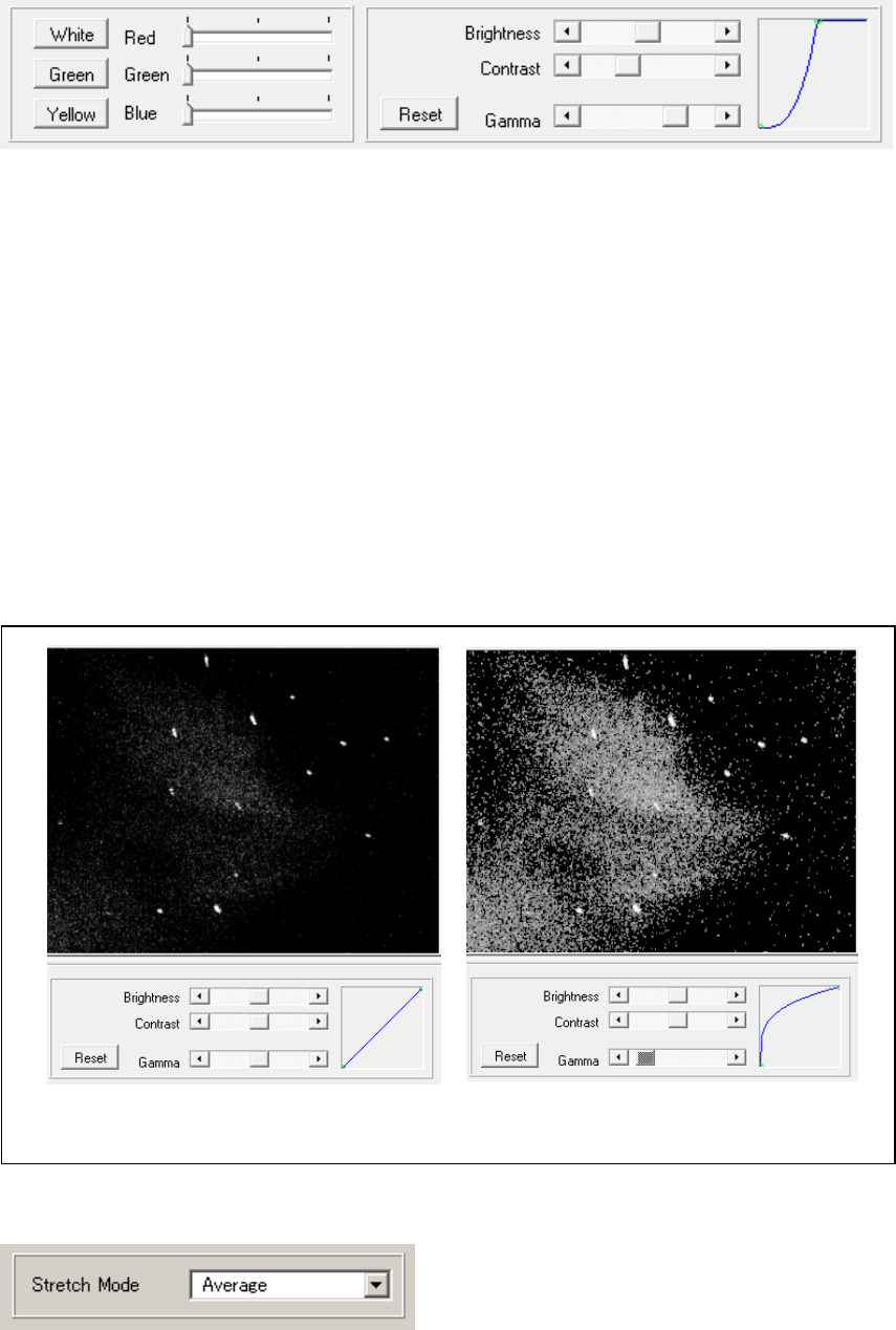
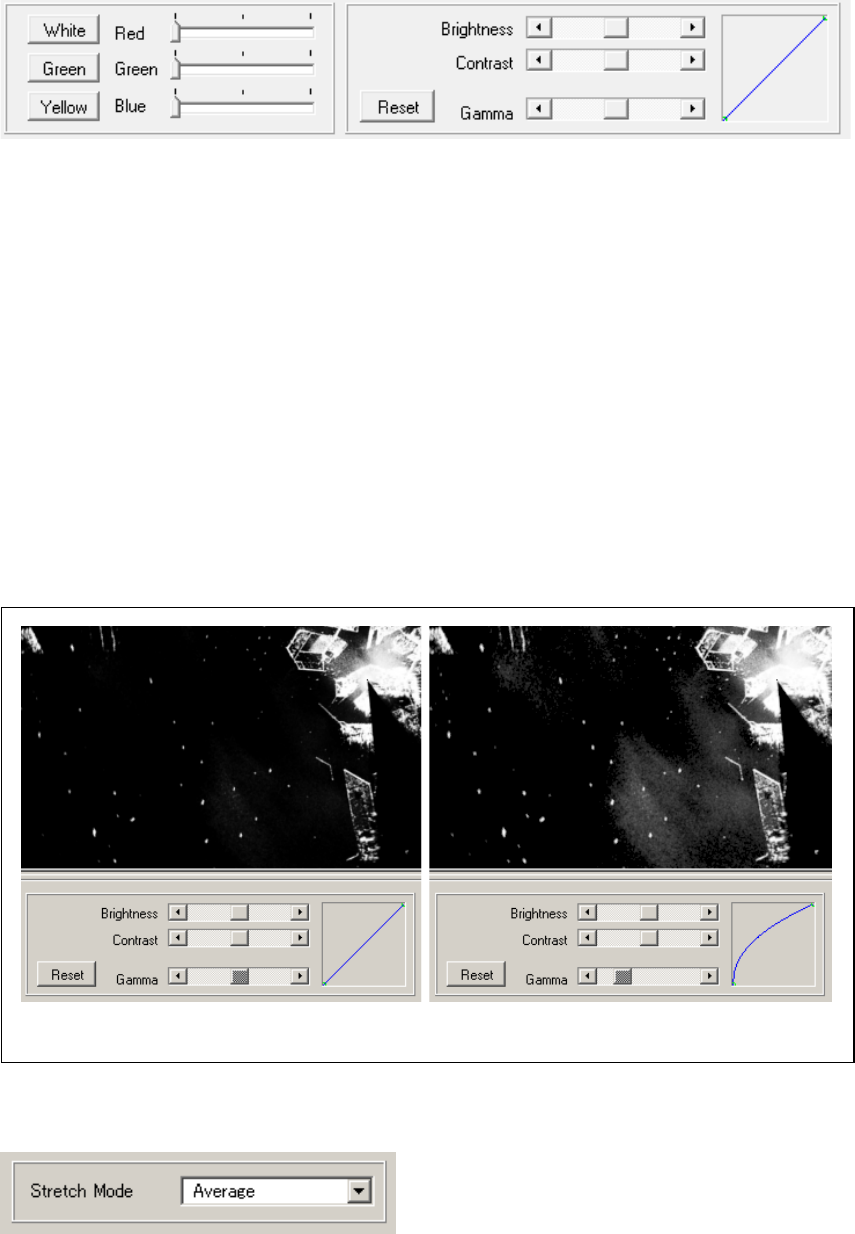
3) Color
Depiction time
Interval
7ZPRR002
31
White Button: Sets the radar picture display color to white monochrome.
Green Button: Sets the radar picture display color to green monochrome.
Yellow Button: Sets the radar picture display color to yellow monochrome.
Red Slide Bar: Adjusts the red level of radar picture color.
Green Slide Bar: Adjusts the green level of radar picture color.
Blue Slide Bar: Adjusts the blue level of radar picture color.
Reset Button: Resets the gradation curvature.
Brightness Scroll Bar: Adjusts the brightness of gradation curvature.
Contrast Scroll Bar: Adjusts the contrast of gradation curvature.
Gamma Scroll Bar: Adjusts the gamma level of gradation curvature.
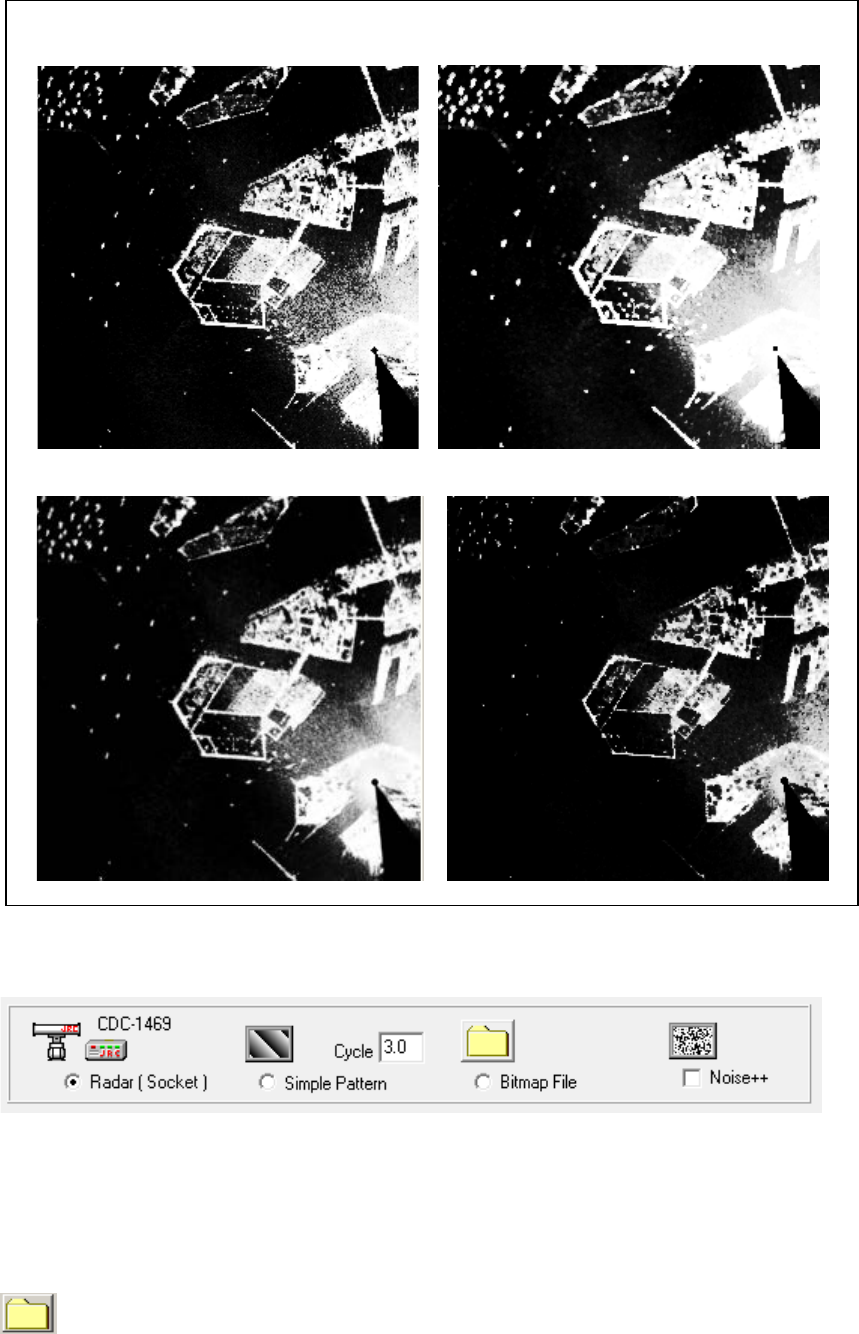
4) Stretch Mode
Stretch Mode: Selects the pixel composite method for B-scope conversion.
・None : Pixel composition is not carried out.
・Peak Hold :Maximum value is used.
・Average : Average value is used.
Example of Adjusting of gamma level
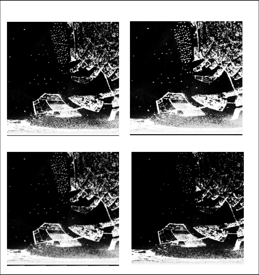
7ZPRR002
32
None
Average
Peak Hold
Minimum
・Minimum : Minimum value is used.
(3) PPI Scope
7ZPRR002
33
: Image update is stopped when this switch turned ON.
: Shows cursor position in the picture.
: Moves picture position. (Off-Center)
:Expand the position of cursor. (Zoom-in)
: Reduce the position of cursor. (Zoom-out)
: Shows display range and range marker interval.
Rng. : Displays distance of cursor position.
Azi. : Displays azimuth angle of cursor position.
Input Panel
Radar Azimuth : Displays the radar antenna azimuth angle.
Range Mark : Selects display on/off of the Range Marker.
Azimuth Mark : Selects display on/off of the azimuth marker.
7ZPRR002
34
Histogram : Selects display on/off of the histogram.
: Selects the histogram section width.
1 x 256, 4 x 64, 8 x 32, 16 x 16, 32 x 8
1 x 256 4 x 64 8 x 32
Split Color: Display on/off of the function to classify a radar picture by color to two gradation is
changed.
3D Scope:Selects the 3D display on/off.
7ZPRR002
35
1) Scale
Range: Selects the display range scale. (Range/Range Marker Interval)
• 0.25 / 0.05 NM
• 0.5 / 0.1 NM
• 1 / 0.2 NM
• 2 / 0.5 NM
• 4 / 1 NM
• 8 / 2 NM
• 16 / 5 NM
• 32 / 10 NM
• 64 / 20 NM
• 128 / 50 NM
2) Display Interval
Interval: Presets the update interval of radar picture. (Preset range:10~1000mS)
Lap time: Displays the radar picture depiction lap time.
If an updating cycle is shortened, the load of CPU will increase.
(Please preset according to CPU load)
3) Color
Depiction time
Interval
7ZPRR002
36
White Button: Sets the radar picture display color to white monochrome.
Green Button: Sets the radar picture display color to green monochrome.
Yellow Button: Sets the radar picture display color to yellow monochrome.
Red Slide Bar: Adjusts the red level of radar picture color.
Green Slide Bar: Adjusts the green level of radar picture color.
Blue Slide Bar: Adjusts the blue level of radar picture color.
Reset Button: Resets the gradation curvature.
Brightness Scroll Bar: Adjusts the brightness of gradation curvature.
Contrast Scroll Bar: Adjusts the contrast of gradation curvature.
Gamma Scroll Bar: Adjusts the gamma level of gradation curvature.
4) Stretch Mode
Stretch Mode: Selects the pixel composite method for B-scope conversion.
・None : Pixel composition is not carried out.
・Peak Hold :Maximum value is used.
・Average : Average value is used.
・Minimum : Minimum value is used.
Example of Adjusting of gamma level
7ZPRR002
37
None
Average
Peak Hold
Minimum
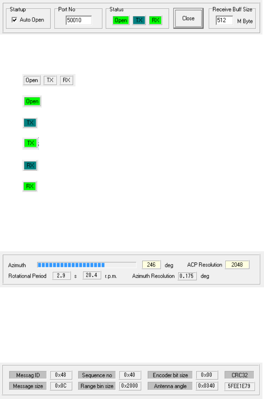
2.4.4.2 Input Image
Selectes the input source
Radar (Socket) : Selects radar signal.
Simple Pattern : Selects the Test Pattern.
Cycle: Presets the test pattern rotation speed.
Bitmap File: Makes the bitmap file.
: Selects the bitmap file.
Noise++ : Superimpose the noise signal. (This setup is not saved.)
7ZPRR002
38
(1) Socket
The TCP/IP UDP client socket for connecting with radar signal processing equipment (CDC-
1469) on NTG-420 SSTRX is set up.
Startup – Auto Open: Automatically sets the socket to the application startup in the case to be open.
Port No: Presets the receiving port number of UDP socket.
Status : Status of UDP socket.
: Close
: Open
: Ready for Transmission
: Under transmission
: Waiting the receiving
: Under receiving
Open(or Close) Button : Open (or close) the socket
Receive Buff Size : Presets the receiving buffer size. (1 - 512MB)
1) Radar Information
Azimuth : Displays radar antenna azimuth angle. (Latest sweep message angle)
ACP Resolution : Displays ACP resolution.
Rotational Period : Displays Antenna revolution period and rotation speed(rpm).
Azimuth Resolution]: Displays azimuth resolution. (The value which divided 360 degrees by the number
of sweeps)
2) Message1
7ZPRR002
39
Display the header information of the receiving message.
Format of Receiving Message
Type
Size
Description
Header
12 bytes
Message ID (0x48)
Message size(12)
Sequence Number(0 – 255)
Range bin size
Antenna encoder bit number(0x00:11,0x01:12)
Antenna Angle information
CRC32c
Sweep data
Range bin size
+3bytes
Message ID (0 x 44)
Message size(Range bin size + 3)
Data (Echo strength data)
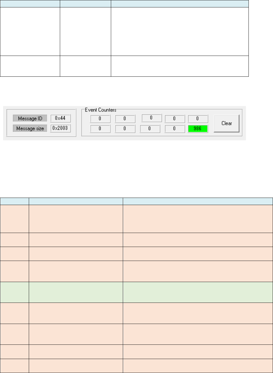
3) Message2 & Counters
Message ID :Displays the message ID of sweep data (0 x 44).
Message Size :Displays the message size of sweep data.
*Message size = Range bin size+3.
Event Counters :Displays event counters of sweep message receiving process.
Contents of event counters
Location
Outline
Detailed
Upper1
It is interrupted 2 seconds or
more during message reception.
If received during the reception of the message is
interrupted for two seconds, and discard the message
received up to the middle of its sweep. The number of
times.
Upper2
Sequence number error
Number of times that the header sequence number is
not correctly incremented.
Upper3
Azimuth error(skipping)
Number of times that the angle is open more than
once of the orientation information in the header.
Upper4
Invalid data before Header
In a state of waiting for reception of the header, bytes
on read-and-
discard mode of data that is not
recognized as a header.
Upper5
Split receiving of header
In a state of waiting for reception of the header, the
h
eader is received over a plurality of reception
processing. The number of times.
Lower1
Sweep data ID error
In a state of waiting for the reception of the sweep
data, the number of bytes on read-and-discard mode
when the message ID is not detected.
Lower2
Mismatching of sweep data
range bin number 1
Indicates the number of times the number of data of
the range bins number and sweep data of the header
do not match.
Lower3
Mismatching of sweep data
range bin number 2
Always 0. The counter to be detected above is always
0.
Lower4
Occurrence of exception during
sweep data receiving
Always 0. (Referred to debugging)
7ZPRR002
40
Lower5
Sweep number
Shows maximum sweep number in receved data at 1
time receving by appilication. Indication of whether it
is processed smoothly.
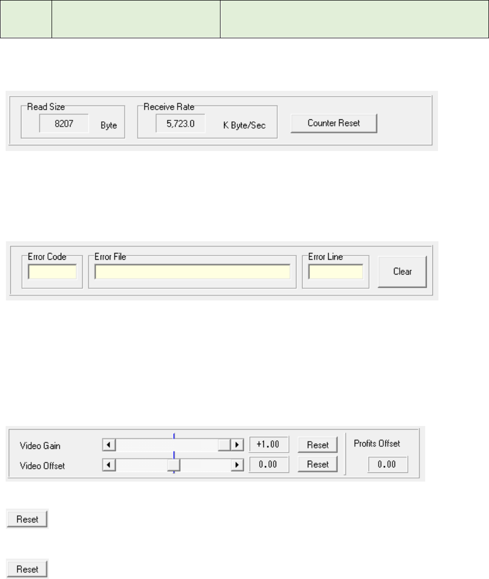
4) Receiving Rate
Read Size: : Display the maximum of the data size processed by one reception processing.
Receive Rate: Display the maximum of the receiving data size per second.
Counter Reset Button: Clear the maximum value of both Read Size and Receive Rate.
5) Error Status
It will display an error of application definition that occurred during the receiving process.
Error Code: Display the error number.
Error File: Display the error of occurred location (source file name).
Error Line: : Display the places that have occurred error (line number on the source file).
Clear Button: Clear the error display.
(2) Video Gain
Video Gain Scroll Bar: Adjust the radar video gain. (-1.00~+1.00)
: Reset the Video Gain to default value. (+1.00)
Video Offset Scroll Bar: Adjust the offset voltage of radar video. (-1.00~+1.00)
: Reset the Video Offset to default value. (0.00)
Profit Offset: Gain offset. This value is controlled by other module.
7ZPRR002
41
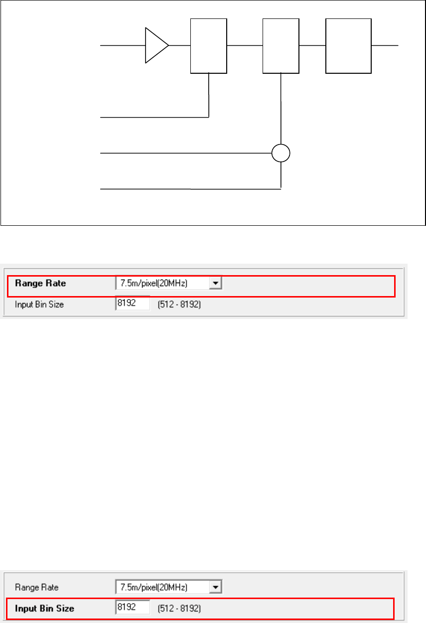
(3) RangeRate
Range Rate: Select the Range Rate (Resolution)
0 - 7.5m/pixel (20MHz)
1 - 15m/pixel (10MHz)
2 - 22.5m/pixel
3 - 30m/pixel (5MHz)
4 - 37.5m/pixel
5 - 45m/pixel
6 - 52.5m/pixel
7 - 60m/pixel (2.5MHz)
8 - 67.5m/pixel
9 - 75m/pixel (2MHz)
10 - 82.5m/pixel
11 - 90m/pixel
12 - 97.5m/pixel
13 - 105m/pixel
14 - 112.5m/pixel
15 - 120m/pixel (1.25MHz)
(4) Input Bin Size
Input Bin Size: Specify the input range bin size. (512 – 8192)
*By shortening the capture range bin size(length), you can reduce the CPU load.
*
+
A/D
+
Video Input
Gain
Offset
Profit
offset
7ZPRR002
42
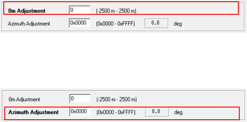
(5) 0m Adjustment
0m Adjustment: Adjust the radar echo start range bin. (-2500m - +2500m))
This adjustment is for adjusting the center of the radar image and shift the radar image on the home
side in pixels.
(6) Azimuth Adjustment
Azimuth Adjustment: Adjust the radar azimuth angle. (0x0000 - 0xFFFF)
This is for radar echo azimuth angle. Resolution is 360/65536(deg.)
7ZPRR002
43
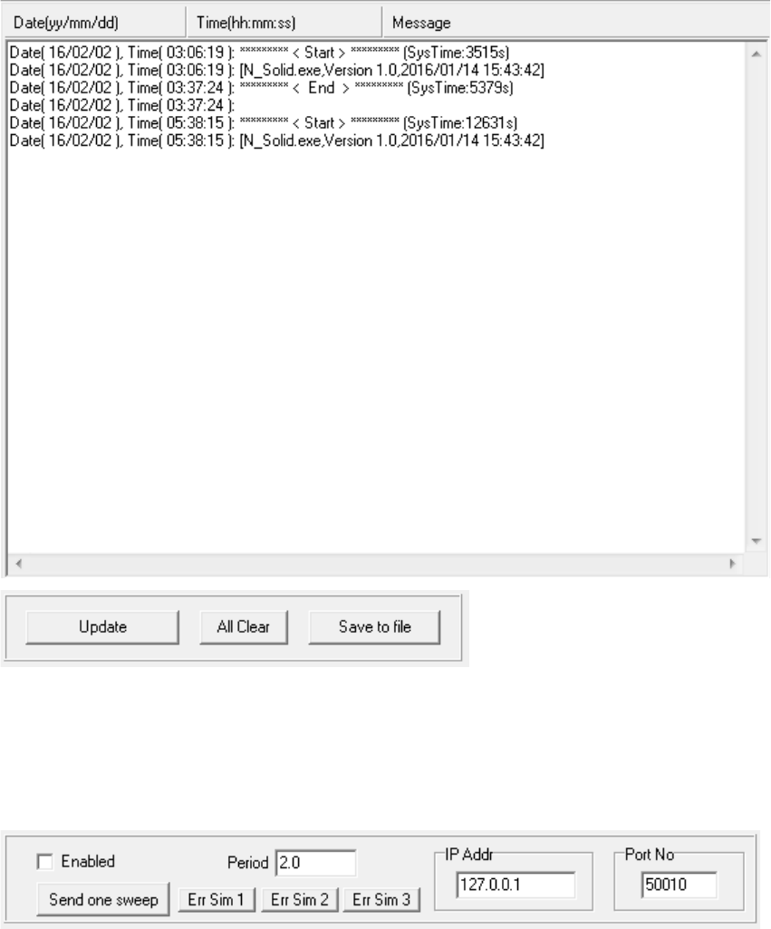
2.4.4.3 Failure history
Failure history will be displayed for the troubleshooting.
Update Button: Update the current logging information.
All Clear Button: Clear the all logging information.
Save to file Button: Save the current logging data with file name.
2.4.4.4 Simulation
This function is to simulate the output of the message of the CDC-1469. It can not use that it has not
Open the receiving socket so to send will use the socket for reception.
Enabled: This is switch for simulation on/off.
Period: Specify the radar antenna rotation speed for the simulation.
IP Addr: Specify the output IP address. (127.0.0.1 is special IP which mean own IP address)
Port No: Specify the output port number.
Send one sweep Button: Outputs the message of one sweep data as single.
Outputs the whether Enabled check box is off.
7ZPRR002
44
Err Sim 1 Button: Outputs the CRC32C of header with taking small interval.
Err Sim 2 Button: Outputs any of the data before header.
Err Sim 3 Button: Lack the message of 1 sweep length.
*These functions are for communication confirmation and debugging.
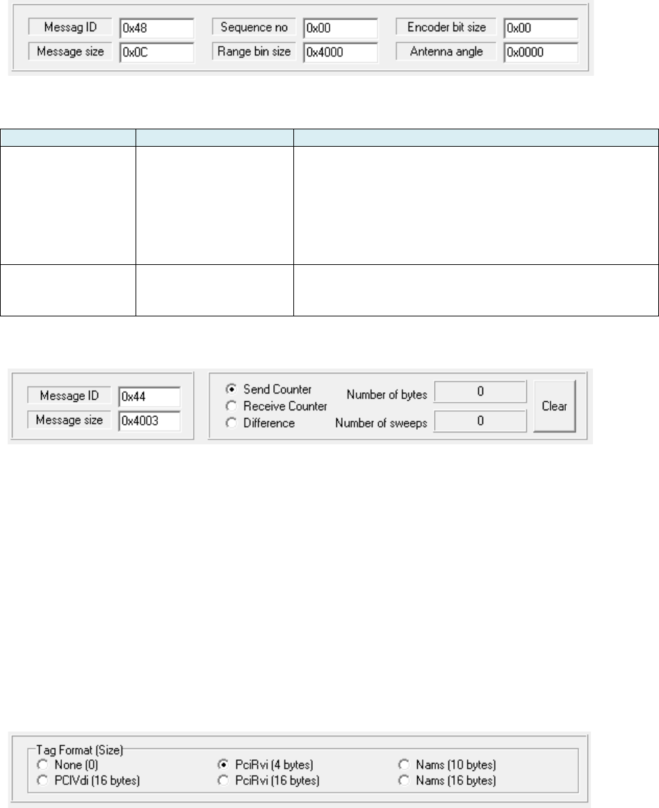
(1) Message1
Specify the header information of simulated sweep message.
Type
Size
Description
Header
12 bytes
Message ID (0x48)
Message size(12)
Sequence Number(0 – 255)
Range bin size
Antenna encoder bit number(0x00:11,0x01:12)
Antenna Angle information
CRC32c
Sweep Data
Range bin size
+ 3 bytes
Message ID (0 x 44)
Message size(Range bin size + 3)
Data (Echo strength data)
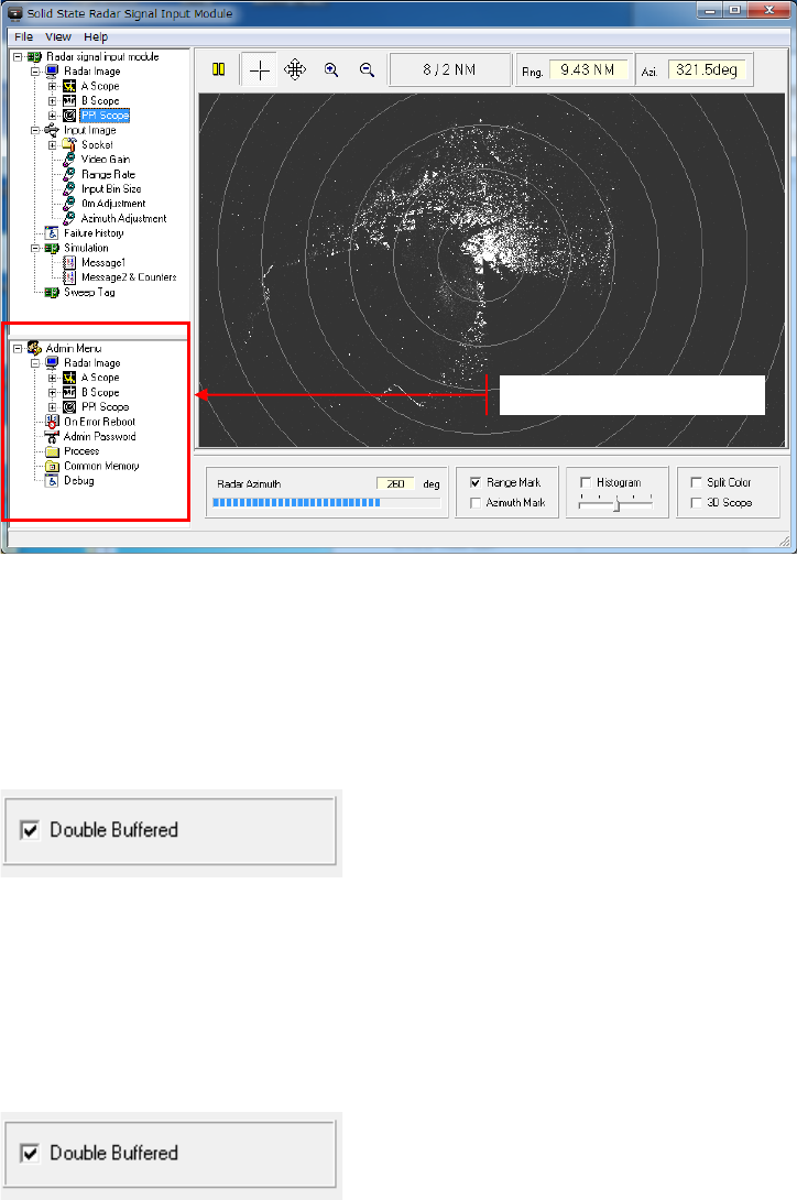
(2) Message2 & Counters
Message ID : Specify the message ID of simulated sweep data (0 x 44).
Message Size : Specify the message size od simulated sweep data.
*Message size = Range bin size+3.
Send Counter : Select the both sending data counter and sweep counter.
Receive Counter: Select the both receiving data counter and sweep counter.
Difference :Select the different. (Send Counter) – (Receive Counter)
Number of bytes: Display the data counter.
Number of sweeps: Display the sweep counter.
Clear Button: Clear the above counter.
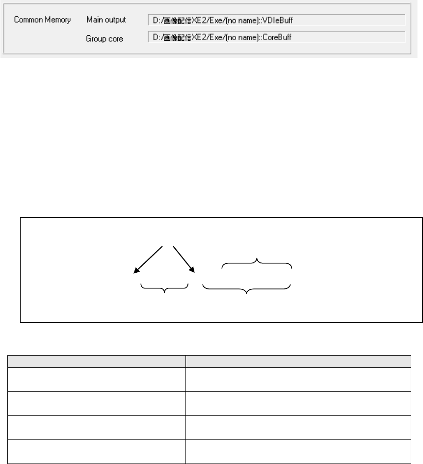
2.4.4.5 Sweep Tag
Tag Format (Size):

7ZPRR002
45
None(0): No hardware Tag.
Range bin
Description
Remarks
4080
~
4095
Padding data 16bytes
0 Fixed
3
~
4079
Radar picture data 3 - 4079
Valid
2
Radar picture data 2
Valid
1
Radar picture data 1
Valid
0
Radar picture data 0
Valid
PciVdo(16): Pci – Vdi format
Range bin
Description
Remarks
16
~
4095
Radar picture data 0 - 4079
Valid
15
Command register H
0 Fixed
14
Command register L
0 Fixed
13
End distance H
Valid
12
End distance L
Valid
11
Start distance H
0 Fixed
10
Start distance L
0 Fixed
9
Times of day H
0 Fixed
8
Times of day L
0 Fixed
7
Dummy
uncertainty
6
PPS counter value H
0 Fixed
5
PPS counter value M
0 Fixed
4
PPS canter value L
0 Fixed
3
External Tag H
0 Fixed
2
External Tag L
0 Fixed
1
Radar antenna azimuth H [65536 / 360]
Valid
0
Radar antenna azimuth L [65536 / 360]
Valid
PciRvi(4) : Pci – Rvi format
Range bin
Description
Remarks
4084
~
4095
Padding data 12 bytes
0 Fixed
4
~
4083
Radar picture data 0 - 4079
Valid
3
External Tag H
0 Fixed
2
External Tag L
0 Fixed
1
Radar antenna azimuth H [65536 / 360]
Valid
0
Radar antenna azimuth L [65536 / 360]
Valid

7ZPRR002
46
PciRvi(16): Pci – Rvi format + 12 bytes padding
Range bin
Description
Remarks
16
~
4095
Radar picture data 0 - 4079
Valid
4
~
15
Padding data 12bytes
0 Fixed
3
External Tag H
0 Fixed
2
External Tag L
0 Fixed
1
Radar antenna azimuth H [65536 / 360]
Valid
0
Radar antenna azimuth L [65536 / 360]
Valid
Nams(10): Nams format
Range bin
Description
Remarks
4090
~
4095
Padding data 6bytes (=0)
0 Fixed
10
~
4089
Radar picture data 0 - 4079
Valid
9
End distance H
Valid
8
End distance L
Valid
7
Start distance H
0 Fixed
6
Start distance L
0 Fixed
5
Radar antenna azimuth H [65536 / 360]
Valid
4
Radar antenna azimuth L [65536 / 360]
Valid
3
PPS times of day H
0 Fixed
2
PPS times of day MH
0 Fixed
1
PPS times of day ML
0 Fixed
0
PPS times of day L
0 Fixed
Nams(16): Nams format + 6bytes padding
Range bin
Description
Remarks
16
~
4095
Radar picture data 0 - 4079
Valid
10
~
15
Padding data 6bytes
0 Fixed
9
End distance H
Valid
8
End distance L
Valid
7
Start distance H
0 Fixed
6
Start distance L
0 Fixed
5
Radar antenna azimuth H [65536 / 360]
Valid
4
Radar antenna azimuth L [65536 / 360]
Valid
3
PPS times of day H
0 Fixed
2
PPS times of day MH
0 Fixed
1
PPS times of day ML
0 Fixed
0
PPS times of day L
0 Fixed
7ZPRR002
47
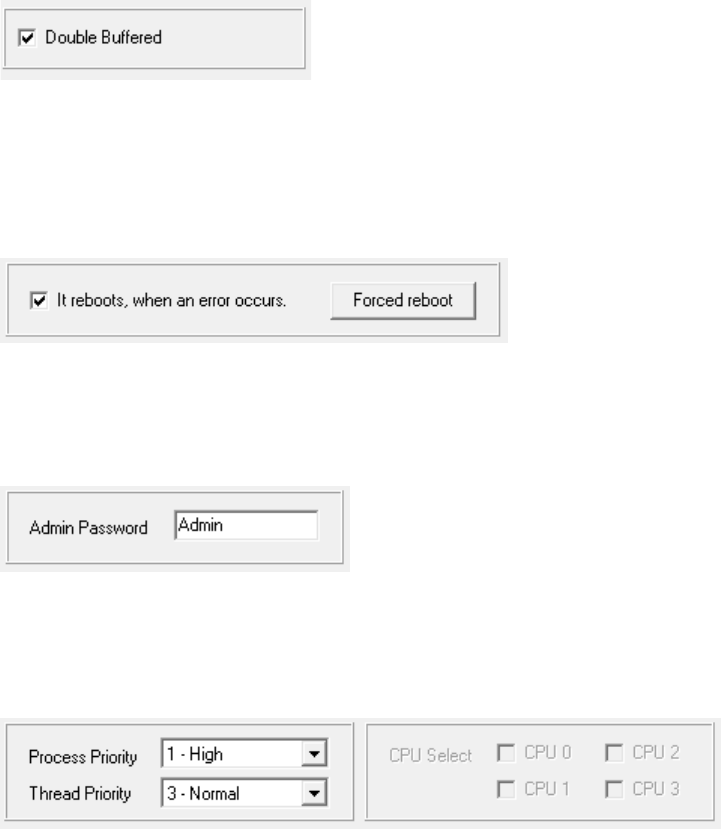
2.5.5 Admin Menu
This menu is a summary of the settings to be performed when the system is introduced. This is
not used in normal. To display this menu, complete the following steps.
i. Click the File of main menu with pushing the Ctrl key.
ii. Select the Admin Menu of Menu.
iii. Push the OK button after input the password.
(Initial password: “Admin”)
2.5.5.1 Radar Image
(1) A Scope
It is an item holder for the A Scope display.
1) Double Buffered
Double Buffered: In case a radar picture is updated, it carries out through a buffer.
Flicker when moving the image will be reduced by this function.
(2) B Scope
It is an item holder for the B Scope display.
1) Double Buffered
Administrator menu
7ZPRR002
48
Double Buffered: In case a radar picture is updated, it carries out through a buffer.
Flicker when moving the image will be reduced by this function.
(3) Ppi Scope
It is an item holder for the Ppi Scope display.
1) Double Buffered
Double Buffered: In case a radar picture is updated, it carries out through a buffer.
Flicker when moving the image will be reduced by this function.
2.5.5.2 On Error Reboot
If reboots, when an error occurs: Reboots the PC at error occurrence.
Forced reboot: Reboots immediately. (Test use)
2.5.5.3 Admin Password
Admin Password: Set the password to enter to display the Administrator menu.
2.5.5.4 Process
Process Priority: Select the application process priority.
0 – Real time High priority
1 - High ↑
2 - Above Normal
3 - Normal
4 - Below Normal ↓
5 - Idle Low priority
Thread Priority: Select the priority of the application's main thread.
0 - Time Critical High priority
1 - Highest ↑
2 - Above Normal
7ZPRR002
49
3 - Normal
4 - Below Normal
5 - Lowest ↓
6 - Idle Low priority
CPU Select: (Not using)
2.5.5.5 Common Memory
It is an interface for providing other applications with a radar picture.
Main output: Output for shared memory name to the image processing module.
Group core: Shared memory name for the final output.
2.5.5.6. Debug
For debugging (No discloser)
2.6 Startup parameter
The format of the command line parameters
The following control is possible by the command line parameter.
Command Line Parameter
Description
/ini=(Initialization file name)
Specify the initialization file.
The default is to N_Solid.ini of module directory.
/log=(Failure log file name)
Specify the failure log file name.
The default is to N_Solid.log of module directory.
/name=(Instance distinguished name)
Specify the unique identification name to create
multiple instances in the PC.
/mem=( Shared memory name)
Specify the name of the destination shared
memory of the captured radar image.
Space
N_Solid.exe /ini=aaa.ini /log=”aadf dsa.log”
No space
Enclosed in a long file name is ""
No space

7ZPRR002
50
3. Specification
Transmitting frequency : Non-chirp pulse 9,410MHz(P0N)
Chirp pulse 9,440 ± 15MHz(Q0N)
Non-Chirp/Chirp pulse (P0N/Q0N) *1
Transmitting power : 200W +1dB, -3dB (100W~251W)*2
Transmitter Type : Solid State Power Amplifier(SSPA)
Transmission pulse width : Refer to Transmission Table(1)
Pulse repetition frequency(PRF) : Refer to Transmission Table(1)
Transmission Table(1)
No.
Pulse width
PRF
Non-chirp
pulse
Chirp
pulse
Non-chirp pulse /Chirp
pulse
0
0.07us
2.8us
0.07us/2.8us
2280Hz
1
0.15us
4.6us
0.15us/4.6us
2280Hz
2
0.3us
9.1us
0.3us/9.1us
2280Hz
3
0.15us
18.3us
0.15/18.3us
1280Hz
4
0.15us
28.0us
0.15us/28.0us
640Hz
5
0.3us
9.1us
0.3us/9.1us
1864Hz
6
0.6us
9.1us
0.6us/9.1us
1280Hz
7
0.07us
2.8us
0.07us/2.8us
4100Hz
Minimum Detection Signal(MDS) : -93dBm or less
A/D Sampling rate : 16bit/84MHz
Pulse compression : Provided
Video Processing function : Interference rejection, CFAR and
Coherent integration
Output signal : Radar video and Trigger
Radar control/monitoring : TCP/IP communication
Power supply : DC48V ± 10%
Power consumption : Less than 130W
Dimensions : 554mm(W) x 330mm(D) x 580mm(H)
(Including Mounting Plate)
Operation temperature range : -15 ~ +50ºC, Non-condensing
Relative humidity : 93% @+40ºC
Storage temperature range : -25 ~ +60ºC
*1: Transmits both P0N and Q0N at simultaneously
*2: Transmitting power is fixed.
2) Radar Control/Monitoring PC display
Hardware
PC Model : HP Z230 or equivalent/ 32 or 64bit Model
CPU : Xeon 2.8GHz or more
Memory : 4Gbyets or more
Hard Disk : 500GB or more

7ZPRR002
51
NIC#1 : Gigabit (1000Mbps)
Jumbo Frame more than 9014bytes
NIC#2 : Ethernet (1000Mbps/100Mbps/10Mbps)
OS : Windows 7 Professional (32 or 64bit)
Software
Feature : Radar Control
Radar Condition Monitoring
Radar Echo Display
NTP Time adjustment
VNC Server

7ZPRR002
52
FCC Caution
Changes or modifications not expressly approved by the party responsible for
compliance could void the user’s authority to operate the equipment.
This equipment generates, uses and can radiate radio frequency energy and, if not
installed and used in accordance with the instructions, may cause harmful interference
to radio communications.
However, there is no guarantee that interference will not occur in a particular
installation. If this equipment does cause harmful interference to radio or television
reception, which can be determined by turning the equipment off and on, the user is
encouraged to try to correct the interference by one or more of the following measures:
1) Reorient or relocate the receiving antenna.
2) Increase the separation between the equipment and receiver.
3) Connect the equipment into an outlet on a circuit different from that to which
the receiver is connected.
4) Consult the dealer or an experienced radio/TV technician for help.
This device complies with Part 80 and Part 90 of the FCC rules.
Operation is subject to the following two conditions: (1) this device may not cause
interference, and (2) this device must accept any interference, including interference
that may cause undesired operation of the device.
IC (Indutry Canada)
This device complies with Industry Canada’s licence-exempt RSSs. Operation is
subject to the following two conditions:
(1) This device may not cause interference; and
(2) This device must accept any interference, including interference that may cause
undesired operation of the device.
Le présent appareil est conforme aux CNR d’Industrie Canada applicables aux
appareils radio exempts de licence.
L’exploitation est autorisée aux deux conditions suivantes :
1) l’appareil ne doit pas produire de brouillage;
2) l’utilisateur de l’appareil doit accepter tout brouillage radioélectrique subi, même si le
brouillage est susceptible d’en compromettre le fonctionnement.