Jastec JTBT2100 Vehicle driving logs tracker User Manual
Jastec Co., Ltd. Vehicle driving logs tracker Users Manual
UserManual.wiki
>
Jastec
>
JTBT2100 User Manual
User manual
Navigation menu
Upload a User Manual
Namespaces
Wiki Guide
HTML
PDF
Info
Views
User Manual
Discussion / Help
Navigation

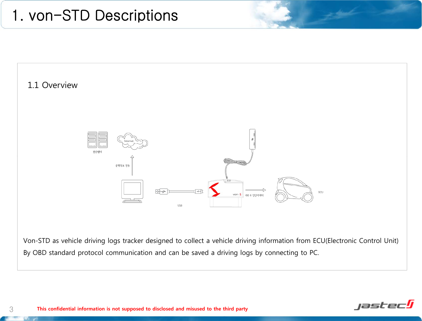
![1. von-STD Descriptions 1 3 Functions1.3 FunctionsSaving vehicle information.Collecting and saving driving logs information.Driving logs record Vehicle identification information / module certification / module serial number information / drivingdata starting time and ending time / ignition On and Off time /Accumulated driving distance / module connection and disconnection time / driving informationtransmitting time / acceleration pedal or throttle valve open angleModule operating check and alarm Display [indicator] : power display lamp[POWER –blue] / status display lamp[STATUS -red]Driving information security Encoded saving data to not modify a driving recorded information.Di iif ti l dUSBtittfdDrivinginformation uploadUSBtransmitter preferred.Power saving function Automatically power will be off when ignition off.Self diagnosticSupportingself diagnostic function throughOBDIImoduleoperatingcheck(Indicator).Self diagnosticpp gggpg()Firmware upgrade support Supporting firmware upgradeThis confidential information is not supposed to disclosed and misused to the third party5](https://usermanual.wiki/Jastec/JTBT2100/User-Guide-1562589-Page-5.png)
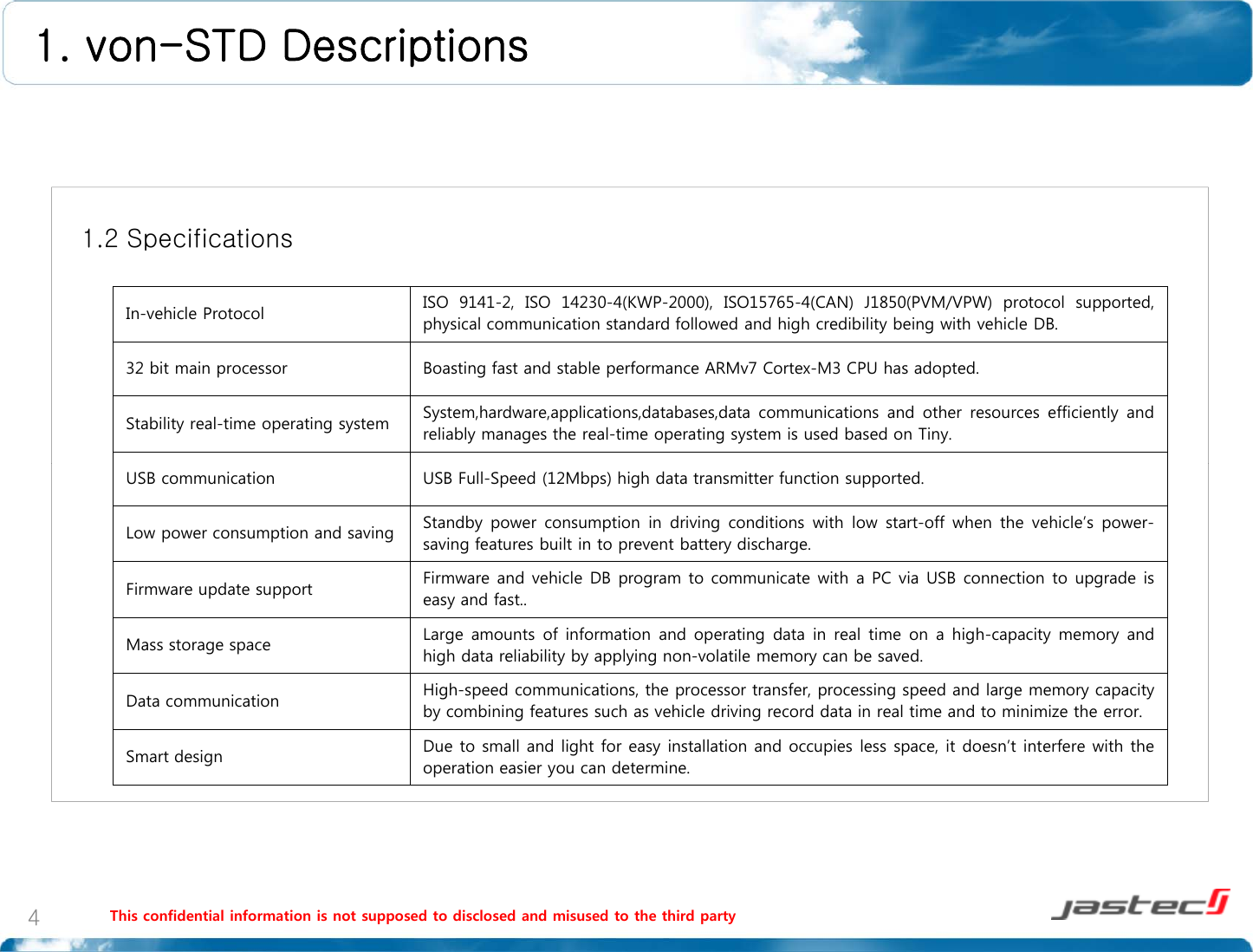
![1. von-STD Descriptions 1.4 SpecificationSpecificationCPU32biARM7CM3External interface specificationUSB11(20Cibl)CPU32bitARMv7Cortex-M3Memory 4 MB Internal Flash MemoryLED Display LEDUSBUSB1.1(2.0Compatible)VCP(Virtual COM Port) SupportedBluetooth(JTBT1100)Bluetooth v2.0 Class 12.4GHz ISM bandF240024835MHVehicle protocolCAN[Control Area Network]: ISO 11898 /ISO 9141-2 / ISO 14230 [KWP 2000] /SAE J1850 (PWM / VPW)Connector type SAE J1962 OBD-II 16Pin Standard Connector(JTBT1100)Frequency range:2,400~2,483.5MHzData Rates: 1 MbpsBluetooth(JTBT2100)Bluetooth v3.0 Class 22.4GHz ISM bandF240024835MHPower DC 12V / 24V vehicle, USB 5.0 V supportPowerconsumptionMax power consumption: ≤500mW low[stand-by] : ≤400mW[saving mode] : ≤30mW(JTBT2100)Frequency range:2,400~2,483.5MHzData Rates: 1 MbpsWiFiIEEE 802.11b/g2.4GHz ISM bandF24002500MHCase Color: Black, Material: ABSSize [W]48mm X [D]28mm X [H]25mmWeight 39 gWiFi(JTWF1100)Frequency range:2,400~2,500MHzData Rates: 1 ~ 54 MbpsTypical TX power: 17dBm±2 @ 802.11b16dBm±2 @ 802.11gThis confidential information is not supposed to disclosed and misused to the third party6Operatingtemperature -30 ~ 80℃](https://usermanual.wiki/Jastec/JTBT2100/User-Guide-1562589-Page-6.png)
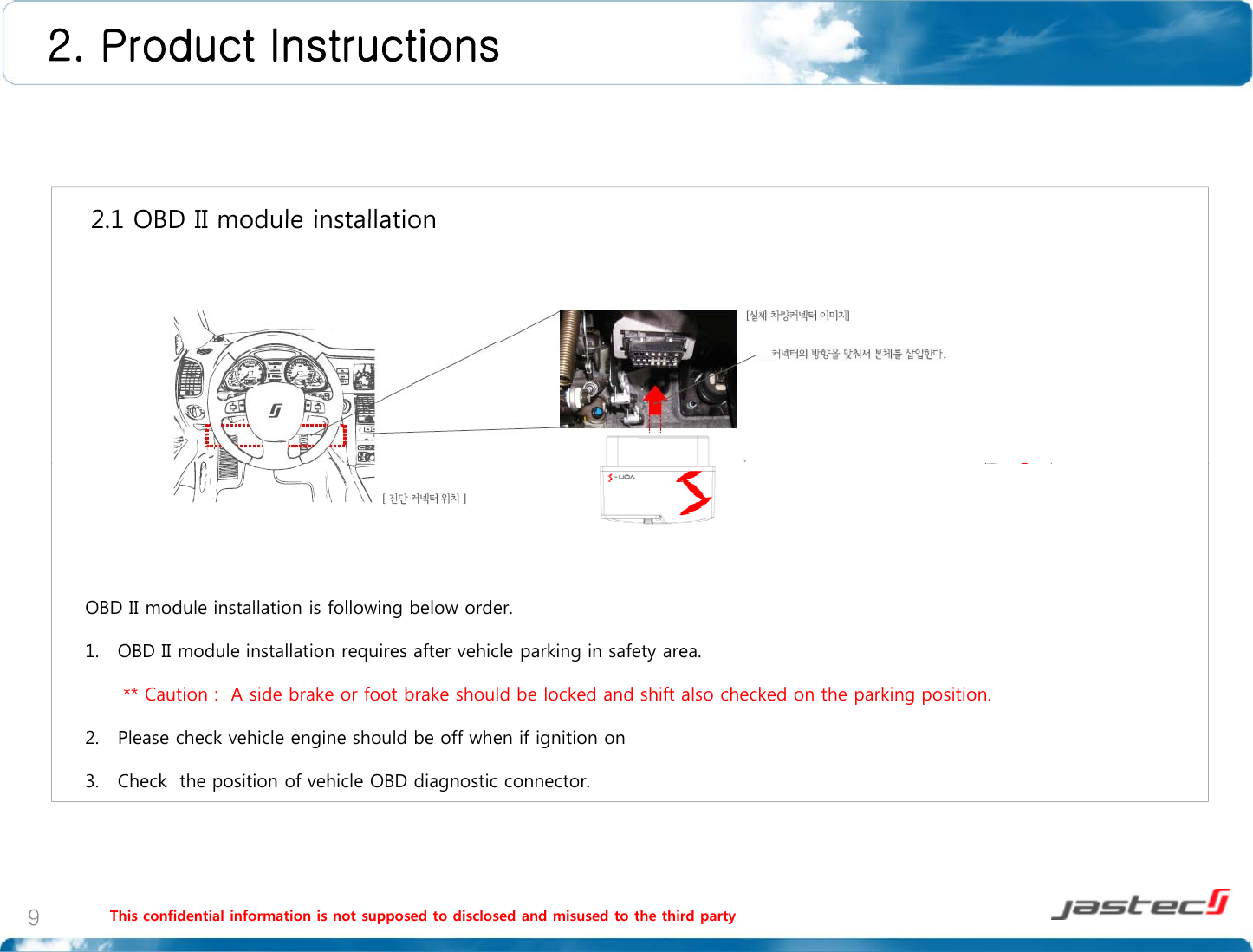
![2. Product Instructions 2 1 OBD II module installation2.1 OBD II module installationOBD II module installation is following below order.4. Connect vehicle OBD diagnostic connector and OBD II module connector.5. Green LED of OBD II module will be blinked every 1 second. 6. Red or Green LED lamp will be continually blinked within 1 minute after ignition on.7. After checking normal installation, green LED lamp blinks every 1 second after ignition off and All LED lamps will be turn off later [saving mode]STATUS Blue LED Red LEDECO driving!(GOOD)ON OFF2.2 LED display statusg()Normal driving! (NORMAL) ON ONBad driving! (BAD) OFF ONWait for connection Blink (1 second interval)OFFError OFF Blink (1 second interval)** Caution : Please contact to customer service center when you have a problem.(1 second interval)Sleep OFF OFThis confidential information is not supposed to disclosed and misused to the third party10](https://usermanual.wiki/Jastec/JTBT2100/User-Guide-1562589-Page-10.png)
![2. Product Instructions 2 4 Driving log data saving and transmitting2.4 Driving log data saving and transmitting 1. Preparation1) PC manager program needs to install to save the driving logs data recorded from OBD II module.* Tip : A program installation manual is available [3. PC Manager installation manual(31~34 page)]2) Please separate OBD II module from vehicle. [2.6 module separation (21 page)] ** Caution : Vehicle data on the status of connecting to vehicle can not be transmitted by USB cable. Please separate OBD II module from vehicle.2. Connection1) OBD II module should be connected to PC USB port by USB cable we provided.2) USB mode display LED lamp will be blinked if connection is normal.This confidential information is not supposed to disclosed and misused to the third party12** Caution : Don’t separate USB cable while PC communicating OBD II module.](https://usermanual.wiki/Jastec/JTBT2100/User-Guide-1562589-Page-12.png)