Jastec JTBT2200 Vehicle driving logs tracker User Manual 1
Jastec Co., Ltd. Vehicle driving logs tracker 1
UserManual.wiki
>
Jastec
>
JTBT2200 User Manual
>
User Manual (installation)
Contents
1.
User Manual (installation)
2.
Quick Start Manual
User Manual (installation)
Navigation menu
Upload a User Manual
Namespaces
Wiki Guide
HTML
PDF
Info
Views
User Manual
Discussion / Help
Navigation

![5 1.3 Functions Driving logs record Saving vehicle information. Collecting and saving driving logs information. Vehicle identification information / module certification / module serial number information / driving data starting time and ending time / ignition On and Off time / Accumulated driving distance / module connection and disconnection time / driving information transmitting time / acceleration pedal or throttle valve open angle Module operating check and alarm Display [indicator] : power display lamp[POWER –blue] / status display lamp[STATUS -red] Driving information security Encoded saving data to not modify a driving recorded information. Driving information upload USB transmitter preferred. Power saving function Automatically power will be off when ignition off. Self diagnostic Supporting self diagnostic function through OBD II module operating check (Indicator). Firmware upgrade support Supporting firmware upgrade 1. von-STD(JTBT2200) Descriptions](https://usermanual.wiki/Jastec/JTBT2200.User-Manual-installation/User-Guide-1890788-Page-6.png)
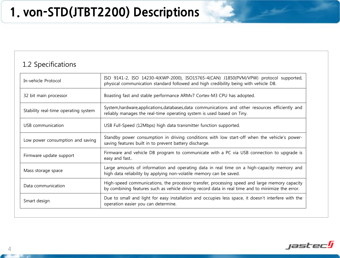
![6 1.4 Specification Specification CPU 32 bit ARMv7 Cortex-M3 Memory 4 MB Internal Flash Memory LED Display LED Vehicle protocol CAN[Control Area Network]: ISO 11898 / ISO 9141-2 / ISO 14230 [KWP 2000] / SAE J1850 (PWM / VPW) Connector type SAE J1962 OBD-II 16Pin Standard Connector Power DC 12V vehicle, USB 5.0 V support Power consumption Max power consumption: ≤500mW low [stand-by] : ≤400mW [saving mode] : ≤30mW Case Color: Black, Material: ABS Size [W]48mm X [D]28mm X [H]25mm Weight 39 g Operating temperature -30 ~ 80℃ External interface specification USB USB 1.1(2.0 Compatible) VCP(Virtual COM Port) Supported Bluetooth (JTBT2200) Bluetooth v3.0 Class 2 2.4GHz ISM band Frequency range: 2,402 ~ 2,480MHz Data Rates: 1 Mbps 1. von-STD(JTBT2200) Descriptions](https://usermanual.wiki/Jastec/JTBT2200.User-Manual-installation/User-Guide-1890788-Page-7.png)
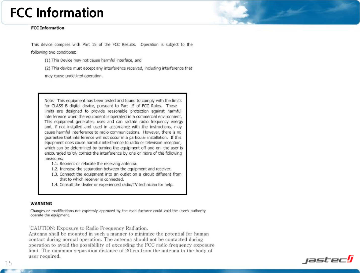
![9 2.1 von-STD(JTBT2200) installation von-STD(JTBT2200) installation is following below order. 1. von-STD(JTBT2200) installation requires after vehicle parking in safety area. ** Caution : A side brake or foot brake should be locked and shift also checked on the parking position. 2. Please check vehicle engine should be off when if ignition on 3. von-STD(JTBT2200) shall be installed in front of driver seat and must be located to ensure a separation distance of 5mm or more between the antenna and the driver/passenger to comply with FCC RF exposure requirements. 4. Check the position of vehicle OBD diagnostic connector. 2. Product Instructions Min. 20cm [Vehicle OBD diagnostic Connector]](https://usermanual.wiki/Jastec/JTBT2200.User-Manual-installation/User-Guide-1890788-Page-10.png)
![10 5. Connect vehicle OBD diagnostic connector and von-STD(JTBT2200) connector. 6. Green LED of von-STD(JTBT2200) will be blinked every 1 second. 7. Red or Green LED lamp will be continually blinked within 1 minute after ignition on. 8. After checking normal installation, green LED lamp blinks every 1 second after ignition off and All LED lamps will be turn off later [saving mode] 2. Product Instructions ** Caution : Please contact to customer service center when you have a problem. STATUS Blue LED Red LED ECO driving! (GOOD) ON OFF Normal driving! (NORMAL) ON ON Bad driving! (BAD) OFF ON Wait for connection Blink (1 second interval) OFF Error OFF Blink (1 second interval) Sleep OFF OF 2.2 LED display status](https://usermanual.wiki/Jastec/JTBT2200.User-Manual-installation/User-Guide-1890788-Page-11.png)
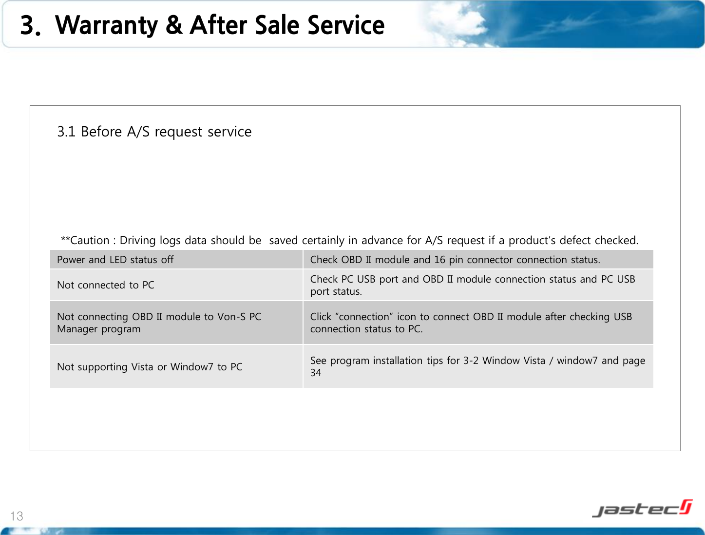
![12 2.4 Driving log data saving and transmitting 1. Preparation 1) PC manager program needs to install to save the driving logs data recorded from OBD II module. * Tip : A program installation manual is available [3. PC Manager installation manual(31~34 page)] 2) Please separate OBD II module from vehicle. [2.6 module separation (21 page)] ** Caution : Vehicle data on the status of connecting to vehicle can not be transmitted by USB cable. Please separate OBD II module from vehicle. 2. Connection 1) OBD II module should be connected to PC USB port by USB cable we provided. 2) USB mode display LED lamp will be blinked if connection is normal. ** Caution : Don’t separate USB cable while PC communicating OBD II module. 2. Product Instructions](https://usermanual.wiki/Jastec/JTBT2200.User-Manual-installation/User-Guide-1890788-Page-13.png)