Jastec JTBT2200 Vehicle driving logs tracker User Manual 1
Jastec Co., Ltd. Vehicle driving logs tracker 1
Jastec >
Contents
- 1. User Manual (installation)
- 2. Quick Start Manual
User Manual (installation)

von-STD(JTBT2200) Manual Instruction

von-STD(JTBT2200) Information
1
•Certified Business Name: Jastec Co.,Ltd.
•Device (model): Wireless data communication system wireless transmitter(JTBT2200)
•Manufactured date: April, 2012
•Manufacturer/country : Jastec Co,Ltd./Korea
•Certified code : JS0
•A radio interference of this wireless module is not providing a service related the safety
of life.

2
We kindly recommend you to be fully aware of using a product accurately and for safety of user. All liabilities by
uncomplying cautions are not supposed to be responsible to manufacturer.
1. This product into water or prolonged exposure to moisture can cause failure resulting in no charge for broken A/S.
2. Do not disassemble or repair this product if the label seal is broken or damaged, free A/S will not be received.
3. Do not separate or equip OBD II module while driving vehicle or ignition off. – This causes to car accident and defective of it.
4. Please note that on the surface of the product carefully to avoid strong detergent or chemicals.
5. This product works under the proper temperature -30~+80℃.
6. Do not impact the product. It’s the cause of product defective.
7. Using other products rated voltage is the cause of the crush. Rated voltage state must be sure to use the product.
8. After parking vehicle in a safe place, install OBD II module then drive.
9. When installing or removing product on the vehicle as the vehicle peripheral device could be due to injury, Please be careful.
10. Incorrect installation of the product by the vehicle’s shock and vibration and can cause data loss, after the installation, please check
it properly.
11. Products by shock or vibration of the vehicle is released from the car because it can cause data loss if the installation status checks
on a regular basis. This product is equipped with a breakdown of the car by the impact of accidents, damage, of driving record, we
are not responsible for missing.
12. Jastec Co.,Ltd provides cable, please use the original cable.
Cautions For Safety
1. von-STD(JTBT2200) Descriptions
3
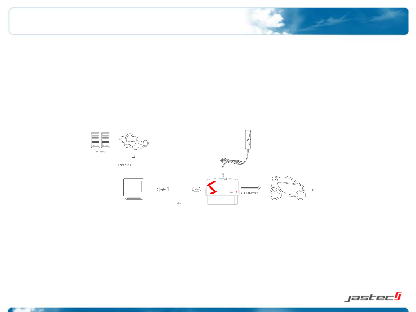
1.1 Overview
von-STD(JTBT2200) as vehicle driving logs tracker designed to collect a vehicle driving information from ECU(Electronic Control Unit)
By OBD standard protocol communication and can be saved a driving logs by connecting to PC.
4
1.2 Specifications
In-vehicle Protocol
ISO 9141-2, ISO 14230-4(KWP-2000), ISO15765-4(CAN) J1850(PVM/VPW) protocol supported,
physical communication standard followed and high credibility being with vehicle DB.
32 bit main processor
Boasting fast and stable performance ARMv7 Cortex-M3 CPU has adopted.
Stability real-time operating system
System,hardware,applications,databases,data communications and other resources efficiently and
reliably manages the real-time operating system is used based on Tiny.
USB communication
USB Full-Speed (12Mbps) high data transmitter function supported.
Low power consumption and saving
Standby power consumption in driving conditions with low start-off when the vehicle’s power-
saving features built in to prevent battery discharge.
Firmware update support
Firmware and vehicle DB program to communicate with a PC via USB connection to upgrade is
easy and fast..
Mass storage space
Large amounts of information and operating data in real time on a high-capacity memory and
high data reliability by applying non-volatile memory can be saved.
Data communication
High-speed communications, the processor transfer, processing speed and large memory capacity
by combining features such as vehicle driving record data in real time and to minimize the error.
Smart design
Due to small and light for easy installation and occupies less space, it doesn’t interfere with the
operation easier you can determine.
1. von-STD(JTBT2200) Descriptions
5
1.3 Functions
Driving logs record
Saving vehicle information.
Collecting and saving driving logs information.
Vehicle identification information / module certification / module serial number information / driving
data starting time and ending time / ignition On and Off time /
Accumulated driving distance / module connection and disconnection time / driving information
transmitting time / acceleration pedal or throttle valve open angle
Module operating check and alarm
Display [indicator] : power display lamp[POWER –blue] / status display lamp[STATUS -red]
Driving information security
Encoded saving data to not modify a driving recorded information.
Driving information upload
USB transmitter preferred.
Power saving function
Automatically power will be off when ignition off.
Self diagnostic
Supporting self diagnostic function through OBD II module operating check (Indicator).
Firmware upgrade support
Supporting firmware upgrade
1. von-STD(JTBT2200) Descriptions
6
1.4 Specification
Specification
CPU
32 bit ARMv7 Cortex-M3
Memory
4 MB Internal Flash Memory
LED
Display LED
Vehicle protocol
CAN[Control Area Network]: ISO 11898 /
ISO 9141-2 / ISO 14230 [KWP 2000] /
SAE J1850 (PWM / VPW)
Connector type
SAE J1962 OBD-II 16Pin Standard Connector
Power
DC 12V vehicle, USB 5.0 V support
Power
consumption
Max power consumption: ≤500mW low
[stand-by] : ≤400mW
[saving mode] : ≤30mW
Case
Color: Black, Material: ABS
Size
[W]48mm X [D]28mm X [H]25mm
Weight
39 g
Operating
temperature
-30 ~ 80℃
External interface specification
USB
USB 1.1(2.0 Compatible)
VCP(Virtual COM Port) Supported
Bluetooth
(JTBT2200)
Bluetooth v3.0 Class 2
2.4GHz ISM band
Frequency range: 2,402 ~ 2,480MHz
Data Rates: 1 Mbps
1. von-STD(JTBT2200) Descriptions
7
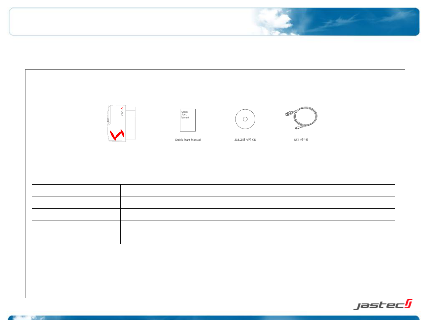
1.5 Composition
Name
Function
OBD II module (body)
Connection to vehicle OBD II connector.
USB cable
Use for uploading the driving logs data by PC connection.
Quick Start Manual
Quick guide manual
Program installation CD
von-S PC Manager installation program, included in user’s manual.
1. von-STD(JTBT2200) Descriptions
8
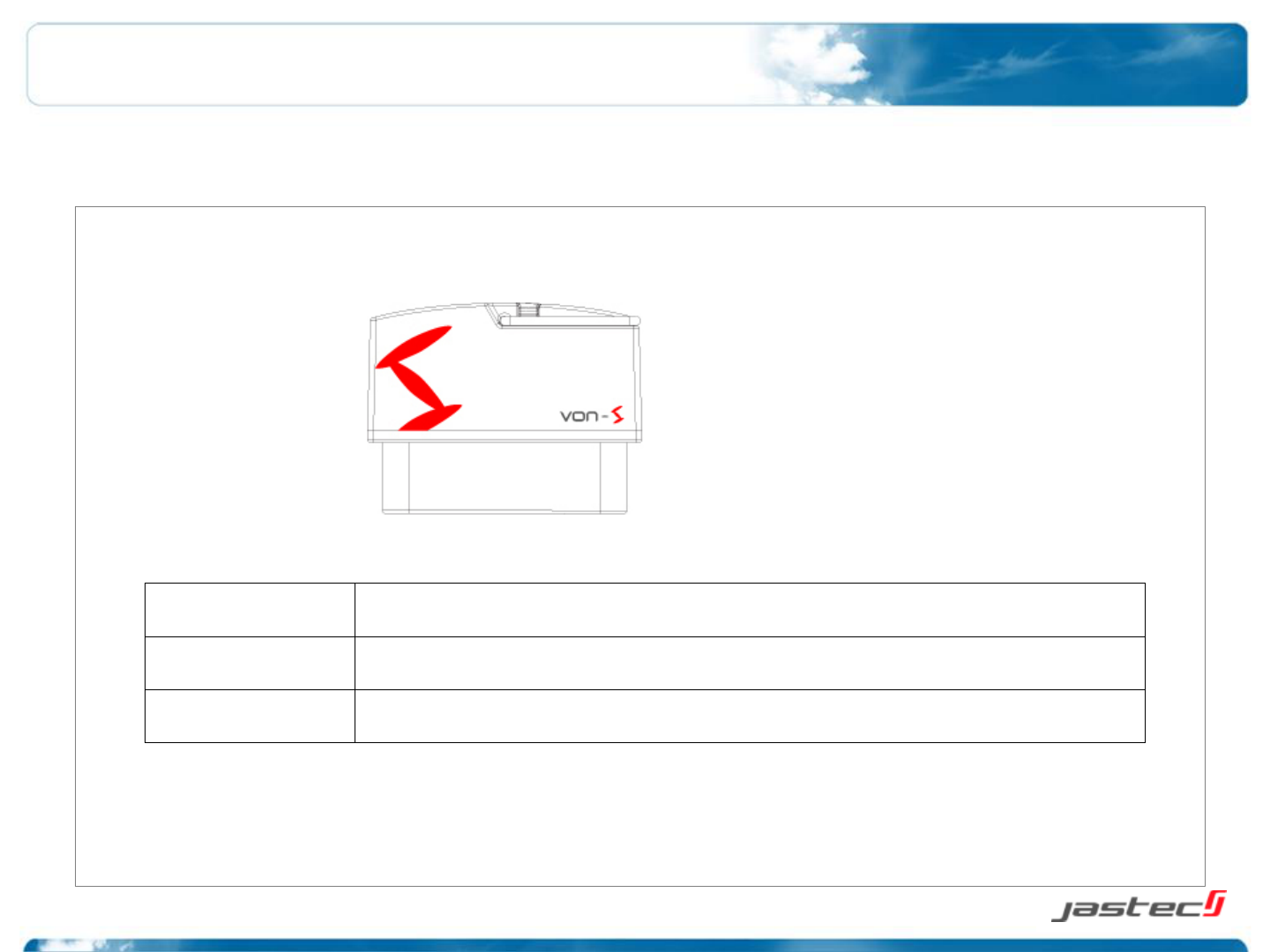
1.6 Body description
Front display LED
Red/Blue/White display LED
OBD connector
Connect to vehicle OBD diagnostic port with SAE J1962 OBD-II 16Pin standard connector.
Rear display LED
Operating LED
1. von-STD(JTBT2200) Descriptions
9
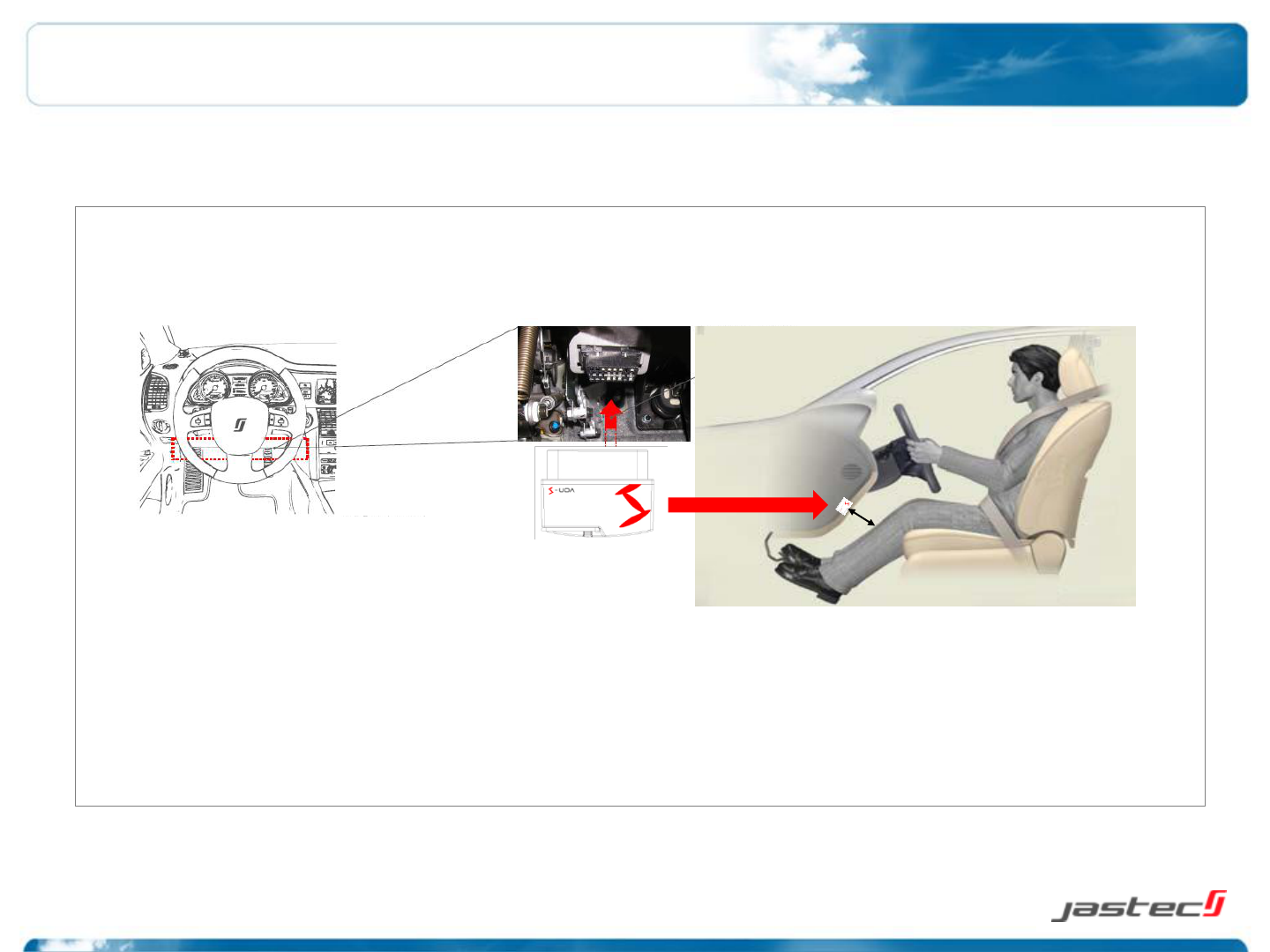
2.1 von-STD(JTBT2200) installation
von-STD(JTBT2200) installation is following below order.
1. von-STD(JTBT2200) installation requires after vehicle parking in safety area.
** Caution : A side brake or foot brake should be locked and shift also checked on the parking position.
2. Please check vehicle engine should be off when if ignition on
3. von-STD(JTBT2200) shall be installed in front of driver seat and must be located to ensure a separation distance of 5mm or
more between the antenna and the driver/passenger to comply with FCC RF exposure requirements.
4. Check the position of vehicle OBD diagnostic connector.
2. Product Instructions
Min.
20cm
[Vehicle OBD
diagnostic Connector]
10
5. Connect vehicle OBD diagnostic connector and von-STD(JTBT2200) connector.
6. Green LED of von-STD(JTBT2200) will be blinked every 1 second.
7. Red or Green LED lamp will be continually blinked within 1 minute after ignition on.
8. After checking normal installation, green LED lamp blinks every 1 second after ignition off and All LED lamps will be turn off later [saving mode]
2. Product Instructions
** Caution : Please contact to customer service center when you have a problem.
STATUS Blue LED Red LED
ECO driving! (GOOD) ON OFF
Normal driving! (NORMAL) ON ON
Bad driving! (BAD) OFF ON
Wait for connection Blink
(1 second interval)
OFF
Error OFF
Blink
(1 second interval)
Sleep OFF OF
2.2 LED display status

11
2.3 OBD II module separation
** Caution : OBD II module separation should be performed at safety area after parking.
** Caution : The separation from vehicle is prohibited if not the purpose of driving data saving or transmitting.
** Caution : Performing OBD II module separation on ignition on may be caused to data loss or module damaged.
1. Turn vehicle ignition off.
2. Pull OBD II module from vehicle OBD diagnostic connector then separating it.
2. Product Instructions
12
2.4 Driving log data saving and transmitting
1. Preparation
1) PC manager program needs to install to save the driving logs data recorded from OBD II module.
* Tip : A program installation manual is available [3. PC Manager installation manual(31~34 page)]
2) Please separate OBD II module from vehicle. [2.6 module separation (21 page)]
** Caution : Vehicle data on the status of connecting to vehicle can not be transmitted by USB cable. Please separate
OBD II module from vehicle.
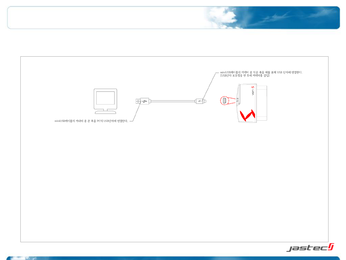
2. Connection
1) OBD II module should be connected to PC USB port by USB cable we provided.
2) USB mode display LED lamp will be blinked if connection is normal.
** Caution : Don’t separate USB cable while PC communicating OBD II module.
2. Product Instructions
3. Warranty & After Sale Service
13
3.1 Before A/S request service
**Caution : Driving logs data should be saved certainly in advance for A/S request if a product’s defect checked.
Power and LED status off
Check OBD II module and 16 pin connector connection status.
Not connected to PC
Check PC USB port and OBD II module connection status and PC USB
port status.
Not connecting OBD II module to Von-S PC
Manager program
Click “connection” icon to connect OBD II module after checking USB
connection status to PC.
Not supporting Vista or Window7 to PC
See program installation tips for 3-2 Window Vista / window7 and page
34

14
3.2 Warranty Service
1. Warranty Period : 1 year
2. Warranty Details
1) Any defective or damage within warranty period can be repaired free A/S service or exchanged as free of charge.
2) Any damage or defective by customer’s misuse is not allowed free exchange or free charged A/S service.
3. Exchange and Return
1) An exchange or return is possible within 1 week after purchase if not opening box.
2) A shipping charge against retuning product because of just customer’s changed mind may be paid by customer.
4. Others
1) Warranty period is valid only for 12 months from manufacturing date if not checking a purchasing date.
2) Repair charge will be billed even though it’s warranty period as below.
- Defective by user’s misuse (impact/flooded/fault)
- Dismantle or alteration by user’s intention.
- Defective by natural disaster.
- Repaired not in official After Sales service centre.
3) Please contact to A/S call service centre for repair charges.
A/S call service : (031-719-5170 Extension : 206)
3. Warranty & After Sale Service
FCC Information
15