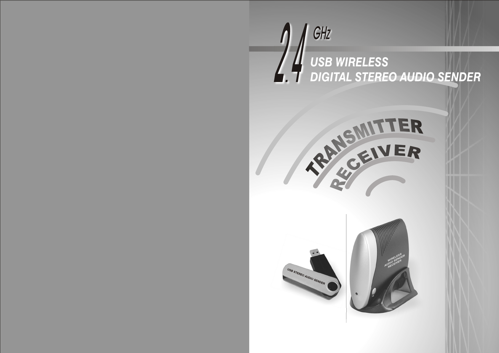
Jebsee Electronics TR-6000 2.4G Wireless Audio Sender User Manual U0805019
Jebsee Electronics Company Ltd 2.4G Wireless Audio Sender U0805019
Manual


4
LIST OF PACKAGED CONTENTS
PRODUCT FEATURES
FEATURES
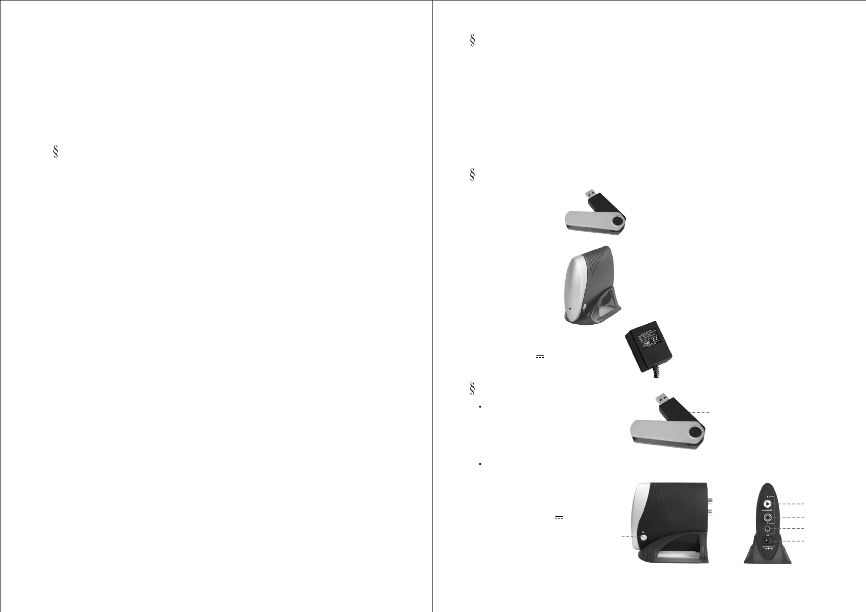
2. One receiver
1. One transmitter
3. One power adapter
(output : 9V 200mA)
Transmitter
1. Channel selection button
1. Right audio input (white)
2. Left audio input (red)
3. Earphone output
4 Channel selection button
. Power input (9V 200mA)
.
5
Receiver
1
WIRELESS
AUDIO SENDER
RECEIVER
USB STEREO AUDIO SENDER
1. Super high frequency for wireless stereo digital audio sender.
2. Transmitter is USB connector, it can be plugged into an USB port of MP3
player using Windows 2000 or above system.
3. High frequency can prevent interference and provides best audio quality.
4. Receiver converts the received digital signal into analog and outputs the
signal to speakers or broadcast speakers.
5. Can be installed easily.
music
analog
USB STEREO AUDIO SENDER
2. Transmitter is USB connector, it can be plugged into an USB port
of MP3 music player using Windows 2000 and above systems.
3. There is no sound from horn or earphone of receiver, try to check
if the LED on USB connector is flashing, if not, please re-plug
USB connector to play songs.
4. The AC adapter, which comes with this system, should not be
plugged into the same outlet with other appliances to reduce
interference probability.
Federal Communication Commission
Interference Statement
1
WIRELESS
AUDIO SENDER
RECEIVER
4
This equipment has been tested and found to comply with the limits for
a Class B digital device, pursuant to Part 15 of the FCC Rules.
These limits are designed to provide reasonable protection against
harmful interference in a residential installation. This equipment generates,
uses and can radiate radio frequency energy and, if not installed and used
in accordance with the instructions, may cause harmful interference to radio
communications. However, there is no guarantee that interference will not
occur in a particular installation. If this equipment does cause harmful
interference to radio or television reception, which can be determined by
turning the equipment off and on, the user is encouraged to try to correct the
interference by one of the following measures:
1. Reorient or relocate the receiving antenna.
2. Increase the separation between the equipment and receiver.
3. Connect the equipment into an outlet on a circuit different from that
to which the receiver is connected.
4. Consult the dealer or an experienced radio/TV technician for help.
FCC Caution: Any changes or modifications not expressly approved by the
party responsible for compliance could void the user's authority to operate
this equipment.
This device complies with Part 15 of the FCC Rules. Operation is subject to
the following two conditions: (1) This device may not cause harmful
interference, and (2) this device must accept any interference received,
including interference that may cause undesired operation.
FCC Radiation Exposure Statement:
This equipment complies with FCC radiation exposure limits set forth fo
r an uncontrolled environment. This equipment should be installed and
operated with minimum distance 20cm between the radiator & your body.
This transmitter must not be co-located or operating in conjunction with
any other antenna or transmitter
IMPORTANT NOTE:
1
2
3
5

CONNECTING THE TRANSMITTER
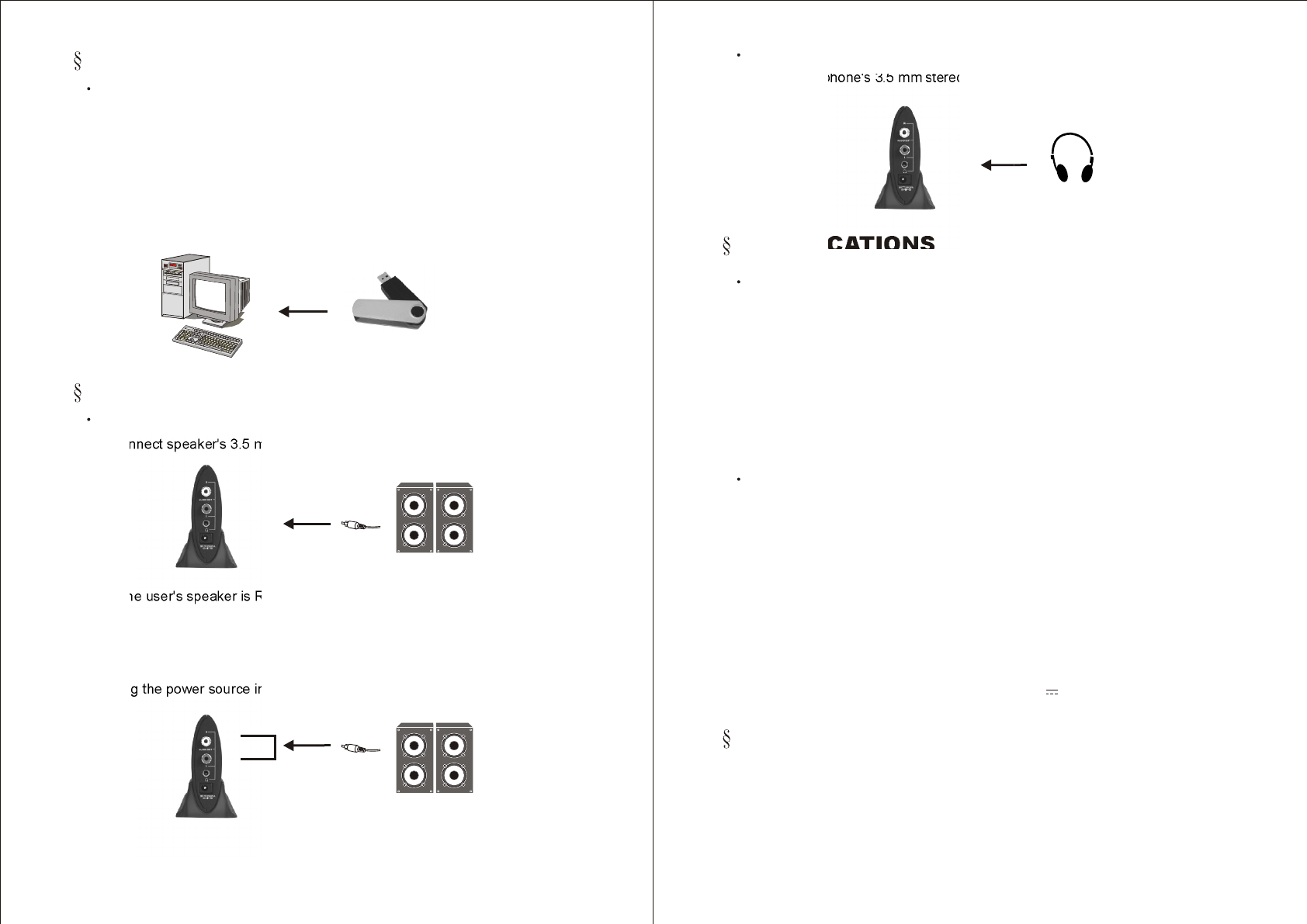
1. Connect transmitter to PC's USB port. When MP3 Broadcast Software
broadcasts music, the transmitter's LED will be flashing. This indicates
that MP3 audio has sent out normally.
2. If during MP3 broadcasting, USB connector is pulled out, then re-plug
in again. The LED at the USB connector will not be flashing the music
must be re-chosen again in the MP3 Broadcast Software. The LED at
the USB connector will start flashing again.
Connect transmitter to PC
2
CONNECTING THE RECEIVER
Connect receiver to speaker
1. Connect speaker's 3.5 mm stereo connector to the receiver's earphone.
2. If the user's speaker is RCA cable based, then connect to the receiver's
R/L output jacks.
3. If the speaker cable connecting to the receiver's R/L output jacks is not
RCA cable, one can consider using a 3.5 mm stereo to RCA cable
converter. Then it can connect to the receiver's R/L output jacks.
4. Plug the power source into receiver's power input jack.
PC
Earphone
R
L
Speaker
Audio
Speaker
USB STEREO AUDIO SENDER
Connect earphone's 3.5 mm stereo connector to the receiver's output
earphone.
Connect receiver to earphone
SPECIFICATIONS
TRANSMITTER :
Frequency range ........................................... 2400MHz~2483.5MHz
Modulation .................................................... FSK
Channel number ........................................... 8
Channel spacing .......................................... 9MHz
Channel frequency ....................................... 2 410MHz, 2 419MHz~2473MHz
Frequency stability ....................................... ± 100KHz
RF output ..................................................... 9.14 dBm
Audio Input .................................................... USB MAIL - Jack (V1.1)
Frequency range .......................................... 2400MHz~2483.5MHz
Channel number ........................................... 8
Channel spacing ........................................... 9MHz
Channel frequency ....................................... 2410MHz, 2419MHz~2473MHz
Frequency stability ....................................... ±100KHz
Audio Output level ....................................... 3.4 Vp-p (Max at 4Vp-p IN)
Audio Output impedance ............................. RCA Jack (L&R), <1KW
Response (I/L) .............................................. 20Hz~20KHz, -3dB
SNR (Signal Noise Ratio) ............................. 87dB (Typical)
Power Requirement ..................................... 9V 200mA ACadapter
RECEIVER :
3
Earphone
1. This system is a wireless communication product. The installation
location should have no blockage to avoid interfering with
transmission and reception. The distance between sender and
receiver should be greater than 30 metres to have every sender
transmit its best signal strength.
NOTES FOR INSTALLING THIS SYSTEM
Ant. Type & Gain ........................................... Inverted-F / 0dBi
Ant. Type ...................................................... Inverted-F