Jehe Technology Development MIH55 Mother Board User Manual Giada MI H55 part1 REV1
Shenzhen jiehe Technology Development Co.,Ltd. Mother Board Giada MI H55 part1 REV1
Contents
- 1. Giada MI-H55_User Manual_part1_REV1
- 2. Giada MI-H55_User Manual_part2_REV1
Giada MI-H55_User Manual_part1_REV1

All rights reserved
www.giada.cc
User's Manual
Version 001

21
Gratitude ……………………………………………………………………………
I. About the product ………………………………………………………………
1. Accessories …………………………………………………………………
2. Picture of the motherboard ………………………………………………
3. Features ……………………………………………………………………
3.1 Processor ………………………………………………………………
3.2 Memory …………………………………………………………………
3.3 BIOS ……………………………………………………………………
3.4 Interfaces of peripherals ………………………………………………
3.5 Power management……………………………………………………
3.6 Expansion slot …………………………………………………………
II. Hardware installation……………………………………………………………
1. Layout of motherboard ……………………………………………………
2. Installing memory …………………………………………………………
3. Install expansion slot card…………………………………………………
3.1 Install graphic card ……………………………………………………
3.2 Install mini-PCIE extend devices ……………………………………
4. Motherboard jumper setting ………………………………………………
4.1 SATA1/SATA2/SATA3/SATA4 …………………………………………
4.2 CPU_FAN1SYS_FAN1…………………………………………………
4.3 CLR_CMOS ……………………………………………………………
4.4 F_USB1/F_USB2 ………………………………………………………
4.5 F_AUDIO ………………………………………………………………
4.6 ATX20P …………………………………………………………………
4.7 F_PANEL ………………………………………………………………
5. Rear panel interface ………………………………………………………
Contents
III. BIOS setting ……………………………………………………………………
1. Main manu …………………………………………………………………
2. Main (Standard BIOS Setup) ……………………………………………
3. Advanced (Advance BIOS Setup) ………………………………………
3.1 CPU configuration ……………………………………………………
3.2 IDE configuration ………………………………………………………
3.3 IO Chipset configuration ………………………………………………
3.4 PC Health configuration ………………………………………………
4. Power…………………………………………………………………………
5. Booting ………………………………………………………………………
6. Security setup ………………………………………………………………
7. Setup for chipset ……………………………………………………………
8. Exit ……………………………………………………………………………
IV. Software installation ……………………………………………………………
1. Install driver for motherboard ……………………………………………
1.1 Install driver for chipset ………………………………………………
1.2 Install sound card driver ………………………………………………
1.3 Install driver for on-board LAN chip …………………………………
1.4 Install driver for graphic card …………………………………………
2. HD_AUDIO and sound card setup ………………………………………
3
4
4
5
5
5
5
6
6
7
8
9
10
11
10
11
12
12
13
14
15
16
17
18
4
5
19
21
23
23
23
24
25
26
27
29
31
33
35
37
37
39
40
41
42
43
4
3
Gratitude I. About the product
Dear Users,
Thank you for choosing Giada “MI” series motherboard .
Giada MI-H55 is based on INTEL LGA1156 processor, support Intel
core i7, i5, i3 and Pentium. The motherboard also supports INTEL Hyper-
Threading technology, 6.4GT/s and 4.8GT/s for QPI, and DDR3
1333/1066MHz memory standards. With on-board six-channel HD-AUDIO
sound card and gigabit LAN. Support HDMI HD display output.
As a highly compatible motherboard, MI-H55 stands out in terms of
performance and price, satisfying needs of application in homes,
offices or DIY.
1 Accessories
Your MI-H55 Motherboard consists of the following accessories. If any of them is
damaged or missing, please contact your local distributor as soon as possible.
.
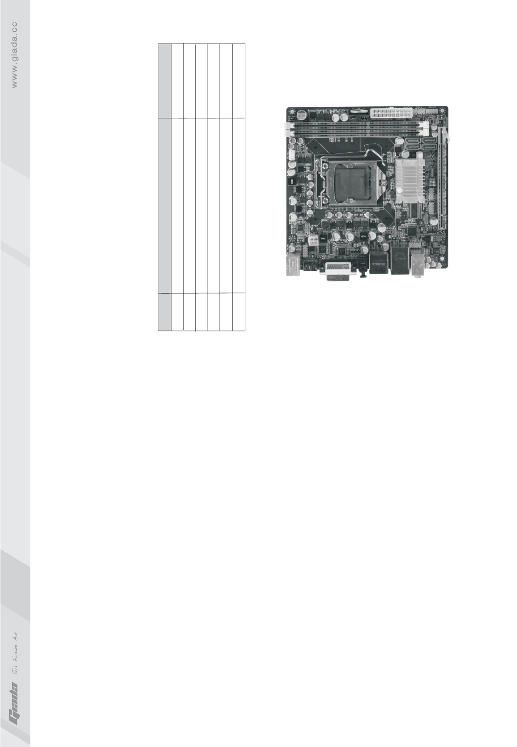
2. Picture of the motherboard
NOTE: This is Giada MI-H55 real product photo show for your reference only,
Product appearance depends on goods.
Item No.
1
2
3
4
5
6
Accessory's name
MI-H55 Motherboard/ I/O baffle
User's Manual
Warranty Card/Certificate of Compliance
Driver's cable
SATA hard-disk cable
Driver's disk
Quantity
1 piece/1 piece
1 copy
1 copy/1 copy
1 piece
2 pieces
1 piece

6
5
· Eight high-speed transmission ports (max. 480Mb/s) which support
USB2.0 and are compatible with USB1.1;
· Supports four SATA II hard-disk interfaces;
· One RJ45 network interface;
· On-board six-channel HD-AUDIO audio adapter;
· Interfaces on panels can be compatible with HDD LED, Speaker, etc.
3.5 Power management
· Support APM and ACPI.
· Compatible with energy star “Green PC”.
3.6 Expansion slot
· One PCI Express x16 AGP
· One MINI-PCIE
3. Features
3.1 Processor
· Supports INTEL LGA1156 processor
3.2 Memory
· Supports 240-Pin DDR3 1333/1066MHz memories * 2;
· 8GB at maximum;
· Supports dual-channel mode.
3.3 BIOS
· Supports PNP, APM and ATAPI;
· Supports ACPI and DMI;
· Automatic detection and supporting hard disk whose LBA mode is over 160G;
· End-users can easily upgrade the motherboard with BIOS.
3.4 Interfaces for peripherals
· One PS/2 keyboard connector;
· One PS/2 mouse connector;
· One HDMI digital interface;
· One DVI interface;
· One VGA interface;
· One SPDIF co-axial audio source interface;
· One E-SATA interface;
8
7
II. Hardware installation
Warning
The motherboard consists of a great number of ICs and other components.
These ICs might be damaged by the static charge. Therefore, the user
must make the following preparations before installation:
· Turn off the power of the computer. It is preferable the power cord be
unplugged.
· Take care not to contact the metal wires and theirs joints on the
motherboard when handling it.
· It is preferable that the operator wear the anti-static wrist strap when
handling the IC components.
· Before the ICs are installed, the components of the motherboard should
be placed on the anti-static mat or bag.
· When you remove the plug on the ATX power supply of the motherboard,
make sure the switch of the power supply is in OFF state.
Installing the motherboard onto the computer case:
For most of the computer cases, the multiple fixing holes left on their
bottoms can be used for securing the motherboard and preventing short
circuit. During your operation, take care not to allow the screws to contact
any circuit or part on PCB. When circuits on the surface of the motherboard
get close to the fixing holes, you can use the plastic sheet to separate the
screws from the board surface so as to avoid damage or failure of the
motherboard.
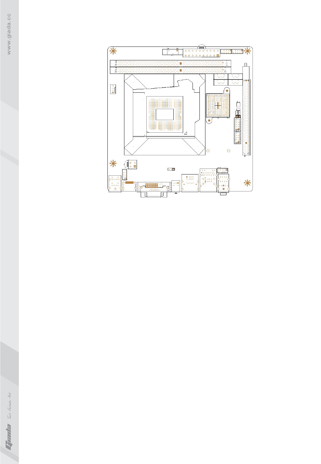
1. Layout of motherboard
10
9
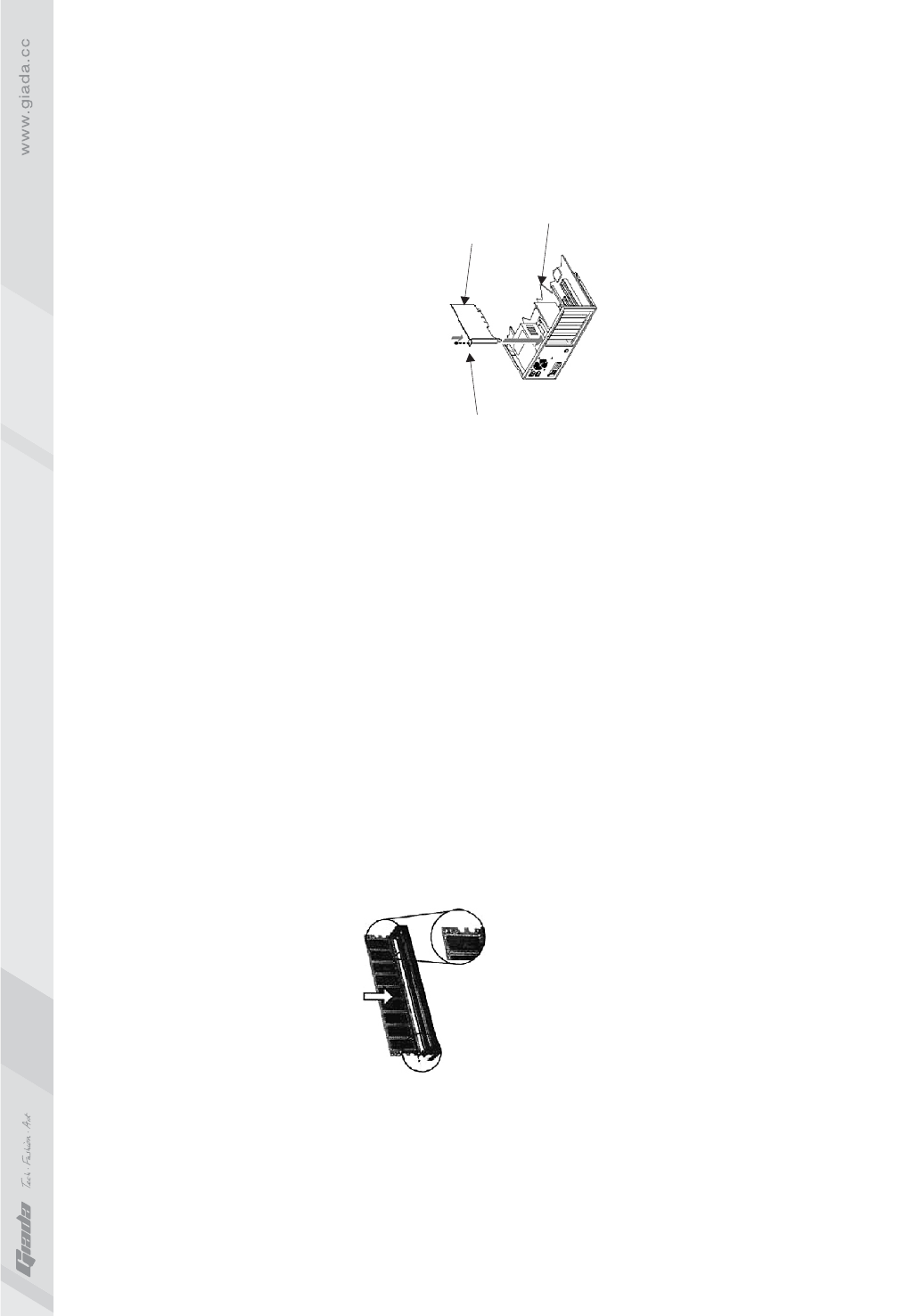
2. Installing memory
Please install the memory in accordance with the following procedures:
· Remove the white buckle at the two ends of the interface slot for the memory;
· Align the golden finger of the memory to the groove of the interface slot and
pay attention the concave hole of golden finger should be aligned to the
convex point of the slot.
· Finally, insert the memory into the interface slot gently. If no error occurs at
the moment, insert the card forward in the slot till the white buckle is
automatically engaged in the concave hole at the two sides of the memory.
Note
In order to avoid damages to the motherboard or the components, the user must
make sure the power supply to the computer is turned off before the memory or
other component is installed or removed. As the groove is set at the golden finger
of the DDR DIMM, the memory can only be inserted into the slot with one direction.
During installation, the user only needs to align the golden finger and the
dual-channel groove of the interface slot and insert it gently. To avoid damage,
never apply excessive force in that process.
3. Install expansion slot card
3.1 Install graphic card
This motherboard provides one interface slot for PCIE 16x AGP. When you
install the PCIE graphic card, you should note that groove of the golden finger
must be exactly engaged into the interface slot. In that process, it is preferable
that you are in grounded state, and you should carefully take out the graphic
card from the anti-static bag. Then align the graphic card to the PCIE slot and
insert it. After that, tighten the screw on the metal baffle.
switch out the white buckle on
both ends of the DIMM Bracket Screw Graphic card
Motherboard
12
11
3.2 Installing Mini-PCIE extended devices
At the rear panel of MI-H55 is a Mini-PCIE extended slot, to which the user
can connected WIFI module and Bluetooth module etc.
4. Install expansion slot card
Note:
The user should notice that all sockets are marked with PIN1. The mark “#”
indicates the ex-factory default values.
4.1. SATA1/SATA2/SATA3/SATA4 (Serial ATA flat-cable sockets)
Serial ATA sockets can reach a transmission speed of 300MB/s, and you can
connect your Serial ATA device to this socket.
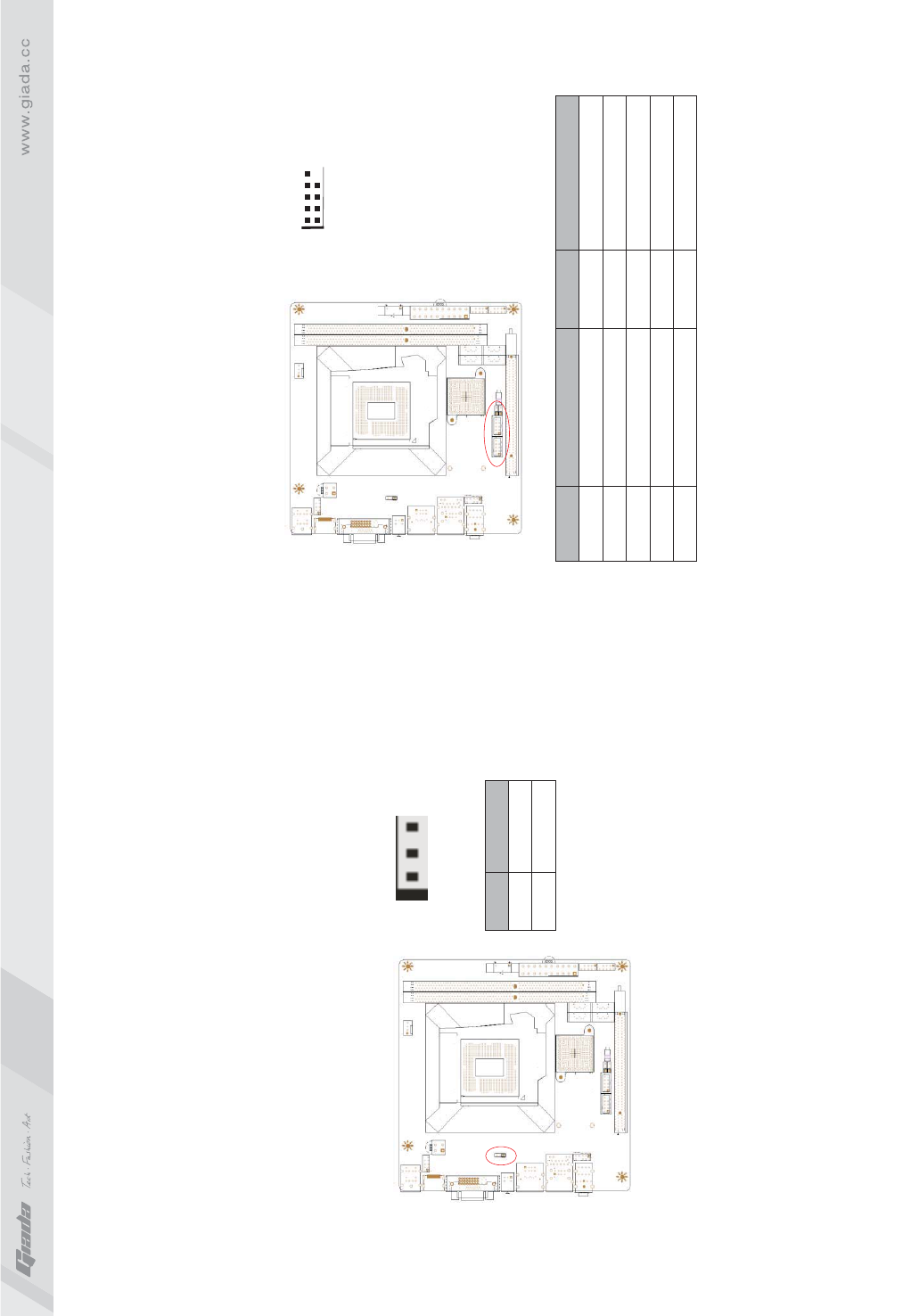
4.2. CPU_FAN1 (CPU FAN socket)
This receptacle can be used for connecting CPU/system fan. Its pins are
defined below. The user shall make sure the fan is conforming.
71
PIN
PIN
Definition
Definition
1
2
3
4
5
6
7
1
2
3
GND
TXP
TXN
GND
RXN
RXP
GND
GND
12V
SIGNAL
123
14
13
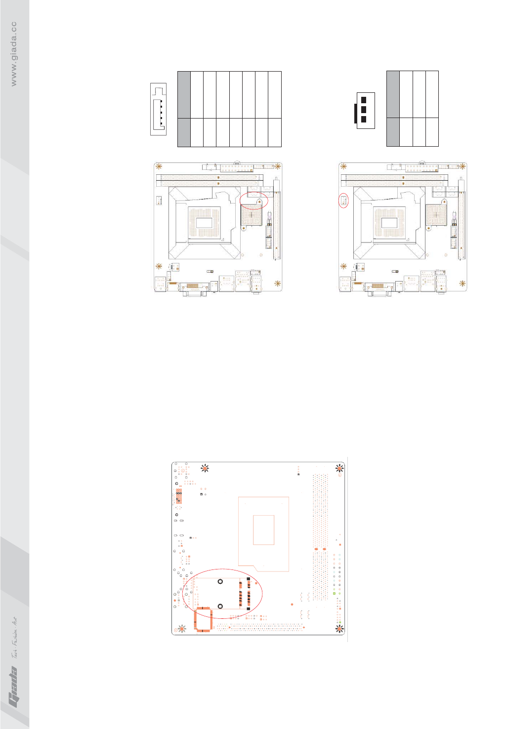
4.3. CLR_CMOS(CMOS pin)
The correct time, system hardware and other information are saved in the
CMOS memory of the motherboard. The interruption the computer's power
won't cause the loss of this information, for the CMOS is powered by the
battery on the motherboard. The port is defined as follows:
PIN
PIN PIN
Definition
Definition Definition
1-2#
2-3
1
3
5
7
9
2
4
6
8
10
Normal
CLR_CMOS
5V
USB D0-
USB D0+
GND
NULL
5V
USB D0-
USB D0+
GND
NULL
4.4. F_USB1/ F_USB2 (frond-end USB pin)
In case the USB ports on the rear panel of the machine case are not enough, the user
can use the two sets of extension USB pins provided by this motherboard. These ports
support USB 2.0 devices. The definitions of the ports are described below:
1
2
10
9
16
15
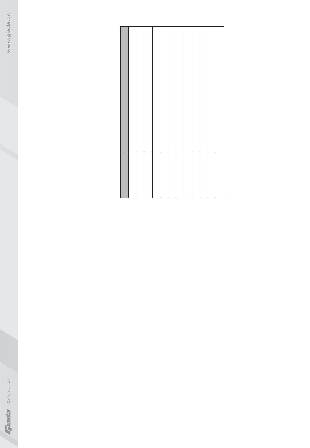
4.5. F_ AUDIO(Pins for front-end audio adapter)
These audio adapter ports allow you to connect to the wire harness of the
audio adapter. After connection, you can easily control the audio
output/microphone through the front panel of the host (Note: Don't connect
the wire to Pin 4).
The definitions of the ports are described below:
PIN PIN
Definition Definition
1
3
5
7
9
2
4
6
8
10
MIC-L
MIC-R
OUT-R
NC
OUT-L
GND
NC
NC
GND
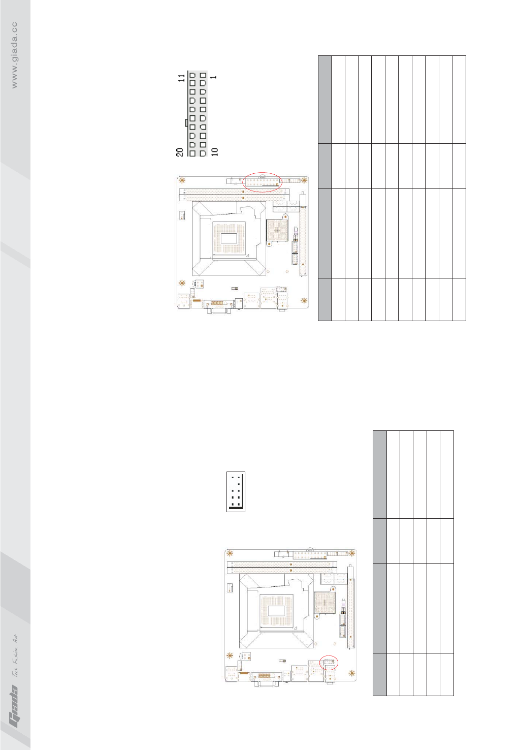
4.6. ATX 20P (Power receptacle)
This socket is used for connecting the 24-pin outlet of the power supply.
The definitions of the pins are described below (when power supply with
20-pin outlet is used, please make sure the numbers are matched correctly):
PIN PIN
Definition Definition
1
2
3
4
5
6
7
8
9
10
11
12
13
14
15
16
17
18
19
20
3.3V
3.3V-
GND
5V
GND
5V
GND
PG
5VSB
12V
3.3V
-12V
GND
PS-ON
GND
GND
GND
-5V
5V
5V
18
17
4.7. F_ PANEL (Front-end control panel)
This socket is used to connect the flat cables on the front-end panel.
PIN PIN
Definition Definition
1
3
5
7
9
2
4
6
8
10
HDLED+
HDLED-
RST-
RST+
NC
PLED+
PLED-
On/Off-
On/Off+
NULL
2
1
4
3
6
5
8
7
10
9
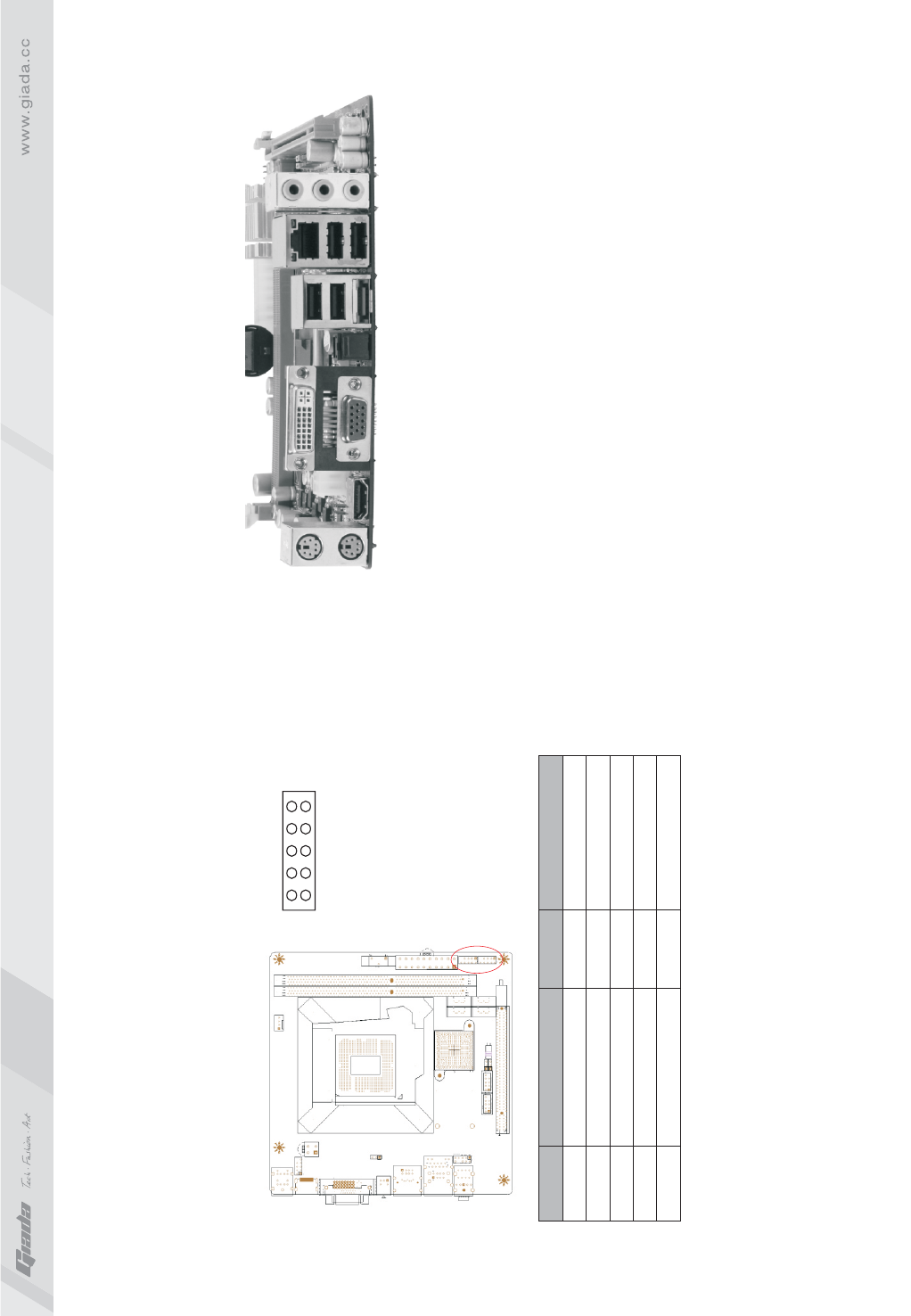
5. Rear panel interface
1. PS/2 keyboard and PS/2 mouse port
This motherboard provides one interface for PS/2 keyboard and one interface for
PS/2 mouse for standard use.
2. HDMI port
3. DVI & VGA port
4. SPDIF port
5. E-SATA and USB port
6. USB port & RJ45 NIC
7. Audio interface
1234 6
75
2019
III. BIOS Setting
Note
The descriptions relating to BIOS in this Manual can only be used for reference
as the BIOS version of the motherboard is upgraded continuously. Giada
provides no guarantee that the contents in this Manual be consistent with the
information you acquire.
BIOS is a basic I/O control program saved in the Flash Memory. Bridging the
motherboard and the operating system, BIOS is used for managing the setup of
the related parameters between them. When the computer is activated, the
system is first controlled by the BIOS program. First, a self-detection called POST
is performed to check all hard devices and confirm the parameters of the
synchronous hardware. Once all detections are completed, BIOS will hand over
the controlling to the operating system (OS). As BIOS serves as the only channel
that connects the hardware and software, whether your computer can run stably
and work in optimized state will hinge on how to properly set the parameters in
BIOS. Therefore, the correct setup of BIOS plays a key role in stably running the
system and optimizing its performance.
The CMOS Setup will save the set parameters in the built-in CMOS SRAM on the
motherboard. When the power is shut off, the lithium battery on the motherboard
will provide continuously power for CMOS SRAM. The BIOS setup program will
allow you to configure the following items:
1.HD drive, floppy drive and peripheral devices;
2.Video display type and display items;
3.Password protection;
4.Power management characteristics.
A.State of BIOS Setup
When the computer is started up, BIOS will run the self-detection (Post) program.
This program includes series of diagnosis fixed in BIOS. When this program is
executed, the following information will appear if any error is found:
Press F1 to Run Setup
Press F 2 to Load default values and continue
Key
↑ (Up key)
↓ (Down key)
← (Left key)
→ (Right key)
ESC
Page Up
Page Down
F1
F7
F8
F9
F10
Function
Move to the previous item
Move to the next item
Move to the left item
Move to the right item
Exit the current interface
Change the setup state, or add the values
Change the setup state, or deduct the values
Display the information of the current setup
Load the set values of previous time
Load the safest values
Load the optimized values
Save the settings and exit the CMOS SETUP
C.Auxiliary information
Main interface
When the system enters the main interface of Setup, the major selected contents
will be displayed at the lower part of the interface with the change of the options.
Set interface
When you set the value for each column, you can view the preset value of the
column and the values that can be set if you press F1, for example, the BIOS
default values or CMOS Setup values. To exit the interface for auxiliary
information, press [ESC].
To enter BIOS, you can press F1; to load the default values and enter the system,
you can press F2. After the self-detection process is completed, you can press
DEL to enter the BIOS interface if no error is found. If the indicative information
disappears before you can act, you can shut off the computer and turn on it again,
or you can press the key RESET on the machine case. To restart your computer,
you can also simultaneously press <Ctrl>+<Alt>+<Delete>.
B. Function Keys definitions
2221
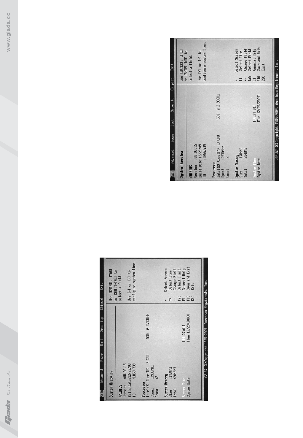
1. Main menu
When the system enters the CMOS Setup menu, you can see the main menu on
the upper part of the screen, as shown in Figure 3.1. In this main menu, you can
use the left and right direction keys to select the setup items. Once the item is
selected, the lower part of the computer screen will show the details of setting.
(The options above and their contents may be different from your actual options,
so they are used for reference only).
· Main (standard CMOS setup)
This item is used for setting the date, time, specifications of hard disk and
floppy disk and type of monitor.
· Advanced (advanced BIOS setup)
This item is used for setting the advanced functions provided by BIOS, such
as the virus alarm and priority order of disks for startup process.
Fig 3.1
· Power (ACPI ) (power management)
This item is used for setting ACPI advanced configuration and power
management.
· Boot (startup configuration characteristics)
· Security (setting the administrator/user password)
· Chipset (setting the performance of the chips)
This item is used for setting the voltage, frequency and other items of
Northbridge, Southbridge, RX780, USB and other devices.
· Exit (option of exit)
This item includes load optimal defaults/load failsafe defaults value/discard
changes/ discard changes and exit.
Fig 3.2
2423
2. Main (standard CMOS setup)
· System time (hh:mm:ss)
Use this item to set the time for the computer, with the format as
“hour/minute/second”.
· System date (mm:dd:yy)
Use this item to set the date for the computer, with the format as “week,
month/day/year”.
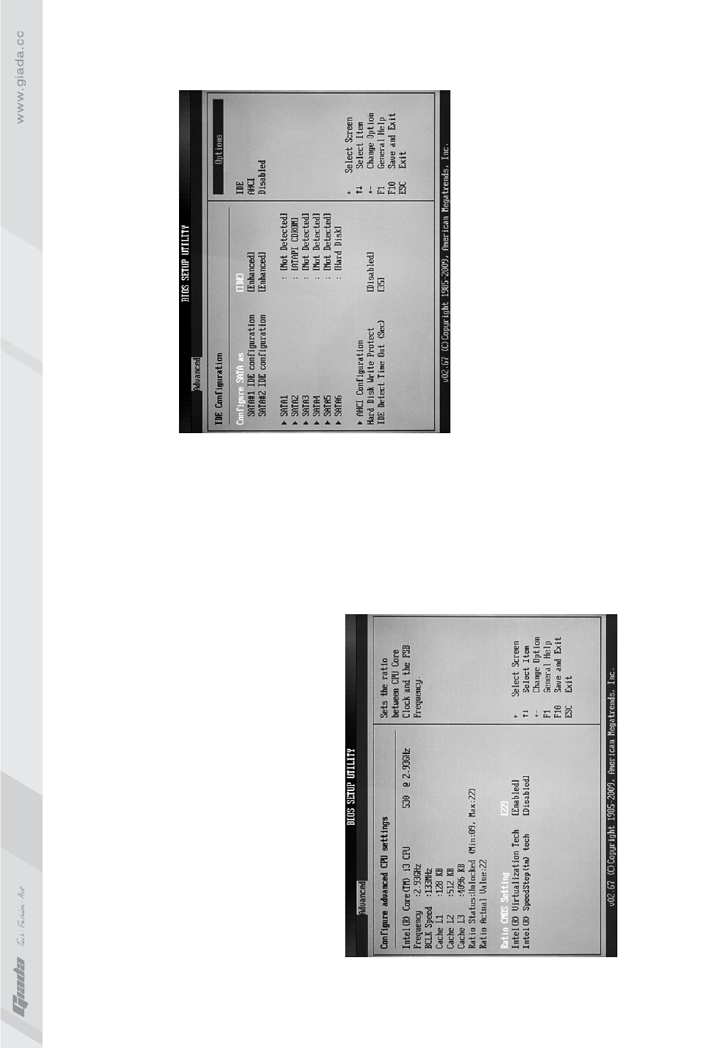
3. Advanced (Advanced BIOS setup)
3.1.CPU Configuration
Fig 3.3
3.2 IDE Configuration
· Hard Disk Write Protect
This item is used for enabling or disabling the function of “write-protect”, and
can only be effective when the device is accessed via BIOS.
· IDE Detect time out (Sec)
This item is used for setting the time in which the system should wait for
automatic detection of ATA/ATAPI device. The options are: [0], [5], [10], [15],
[20], [25], [30] and [35].
Fig 3.4