Jehe Technology Development MIH55 Mother Board User Manual Giada MI H55 part2 REV1
Shenzhen jiehe Technology Development Co.,Ltd. Mother Board Giada MI H55 part2 REV1
Contents
- 1. Giada MI-H55_User Manual_part1_REV1
- 2. Giada MI-H55_User Manual_part2_REV1
Giada MI-H55_User Manual_part2_REV1
26
25
3.3 IO Chipset Configuration
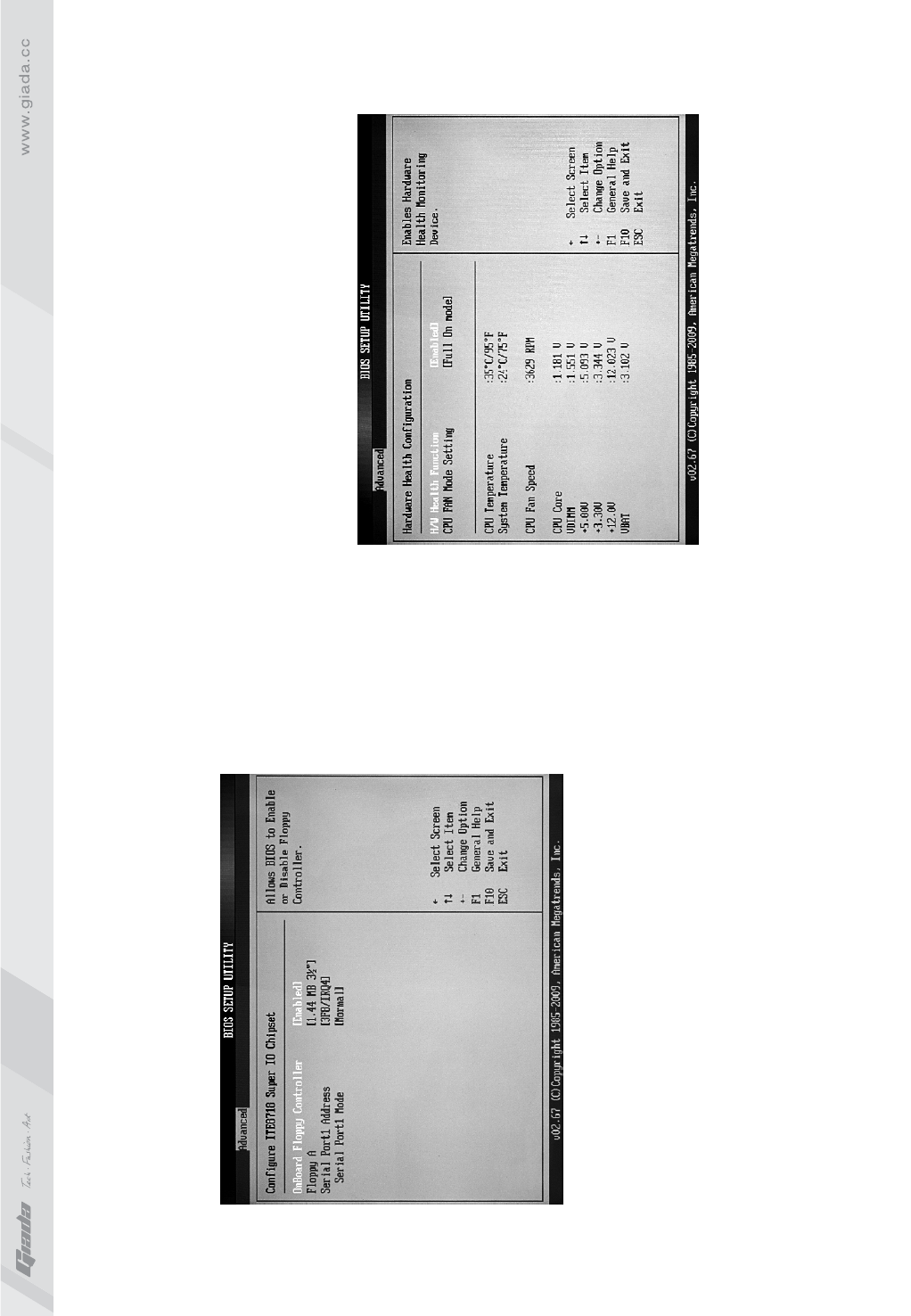
· Serial Port 1 Address (SI 1)
To set the built-in serial port 1 (COM1 port). The options are: D i s a b l e d 、
3F8 / IRQ4, 2F8 / IRQ3, 3E8 / IRQ4, 2E8/ IRQ3 and Auto. The default value
is “3F8 / IRQ4”.
· Serial Port 1 Mode
If set as Normal, it is for the use of regular mouse and Modem.
If IR device (IrDA) is available, it is recommended it be set as IrDA ASKIR.
· Parallel Port Address
To select the address of PI (parallel interface).
Fig 3.5
· Parallel Port Mode
To select the transmission mode (ECP/EPP/Normal) for PI. The default value
is “Normal”.
· Parallel Port IRQ
Set IRQ for PI. It is recommended it be set as “7”.
3.4.PC Health Configuration
· H/W Health Function
Through this item, you can view the state of the system hardware. You can
view the speed of the CPU fan, temperature of CPU and other values.
· CPU Fan Speed Control
To set the CPU fan's mode. Options include Manual Mode and Thermal
Cruise Mode.
Fig 3.6

28
27
4. Power (power management)
·
To set the power type the system can support.
· ACPI APIC support
This item allows you decide whether acpi apic form to rsdt indication list.
Options are [disabled] and [enabled].
· Power Management/APM
This item is used for enabling or disabling the APM (advanced power
management) function. The default value is “Enabled”. When [enabled]
is selected, BIOS can set the system as power-saving mode in
accordance with the later setup even if no operating system provides
any support.
ACPI Version Features
Fig 3.7
· Power Button Mode
The defaulted value ON/OFF indicates that the system will turn ATX
switch into a common shutoff button if the ATX switch is in the pressed-
down state for less than four seconds. If Suspend is selected, it means
the system will enter the sleeping mode if the ATX switch is in the
pressed-down state for less than four seconds. Whatever option is
selected, the system will be shut off if the ATX switch is in the pressed-
down state for over four seconds.
· Restore on AC Power Loss
This item is used for setting what state the system should be in when
the AC power is restored after power interruption. The options and their
definitions are as follows:
· Power On by PCI Card
To start from PCI device.
· Wake-Up by PCIE
To wake up by PCIE.
· RTC Resume
If [Enabled] is selected, you can start the system through real-time clock.
Option
Power Off
Power On
Last State
Definition
To allow the system to be in shutoff state
To allow the system to be started automatically
To allow the system to keep the pre-power off state
3029
5. Booting
·
If this item is set as Enabled, the system can be started within five
seconds and some detection items will be ignored. The options are
[Disabled] and [Enabled].
· Quiet Boot
To start the system quietly.
· Add On ROM Display Mode [Force BIOS]
This item allows you to set the display mode of the device's firmware
program. The options are [Force BIOS] and [Keep Current].
· Bootup Num-Lock
(To set the state of Num Lock after start-up). Options are OFF and ON.
Quick Boot Fig 3.8
In other words, this item can be used for setting the state of Num Lock
for the time the system has been started. It can be set on the basis of
the needs of the user and doesn't affect the performance of the computer.
· PS2 Mouse Support
Set to support PS2 mouse. The available options are [Auto] and
[Disable]. The default value is Auto.
· Wait For“F1” If any Error
(The system waits the user to press F1 if any error occurs from the
computer). The options are Disable and Enable. Normally, it is set as
Enable. Then if the computer has any error, a line of English words will
appear on the screen, reminding the user of pressing F1 to enter CMOS
for setup. If it is set as Disable, that line of English words won't appear.
However, if the words “wait…” appear during the start up process and
you press Del, the system can also enter CMOS for setup.
· Hit “Del” Message Display
(Information is displayed when the computer is started, suggesting the
user can press “Del” to enter the state for CMOS setup). The options
are [Disable] and [Enable]. Normally, [Enable] is selected. After
[Enable] is selected, the information on how to enter the state for
CMOS setup will be displayed at the time the computer is started. If
[Disable] is selected, such information won't be displayed. However,
if you press “Del” when the character “Wait……” appears at the time the
computer is started, the system can also enter the state for CMOS setup.
· Interrupt 19 Capture [Disabled]
If you use some PCI extension cards with built-in firmware program
(like SCSI extension card) and you want to start the system through
Interrupt 19, you can set this item as [Enabled]. The options are
[Disabled] and [Enabled].
32
31
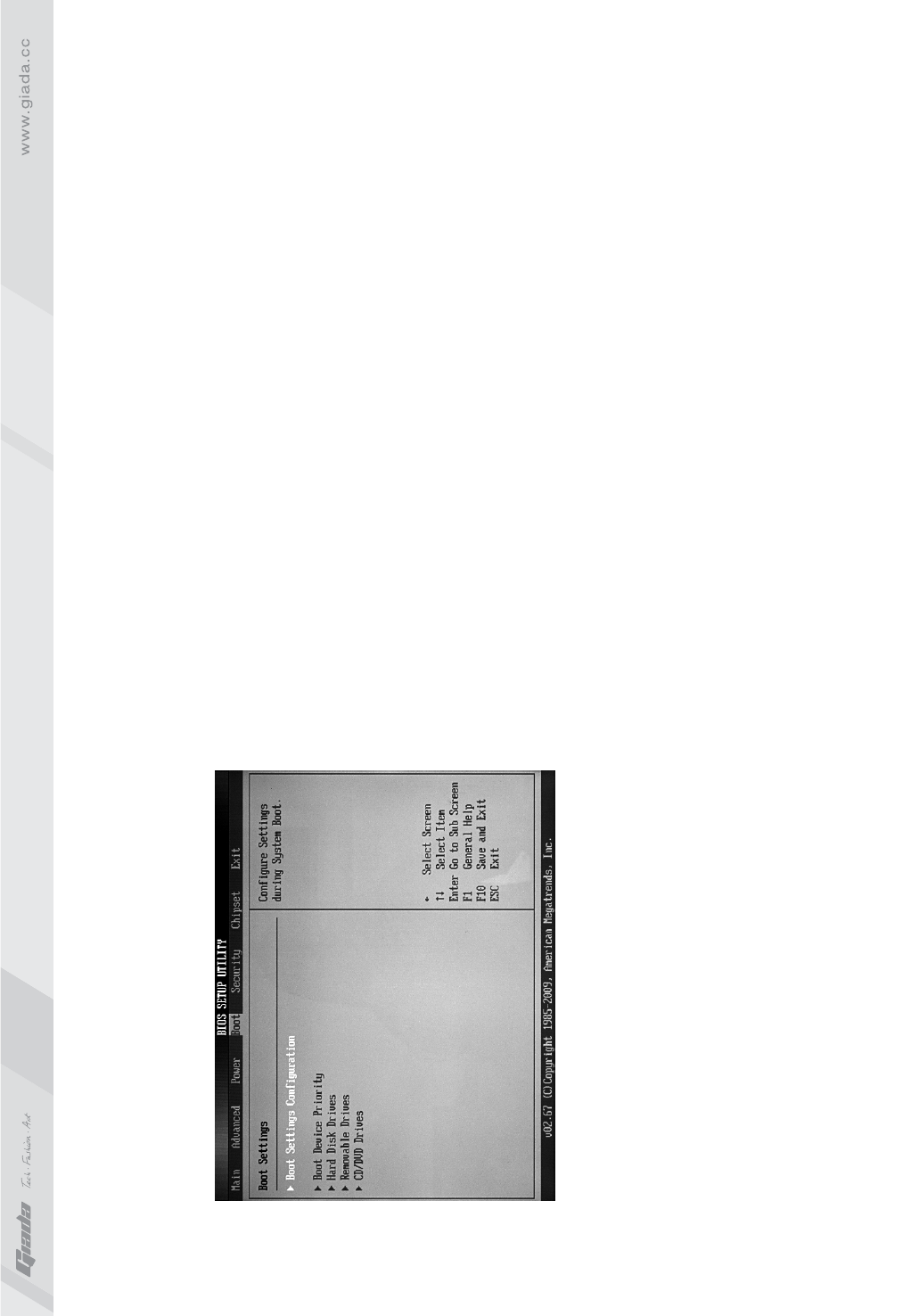
· Boot Device Priority
To set the booting priority.
· Hard Disk Drives
To set the booting priority of hard disk devices.
· Removable Drives
To set the booting priority of removable devices.
· CD/DVD Drives
To set the booting priority of CD/DVD-ROM devices.
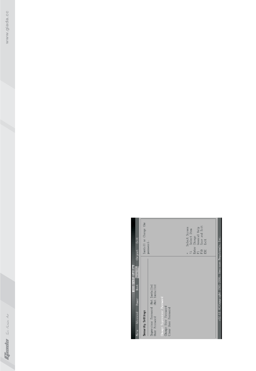
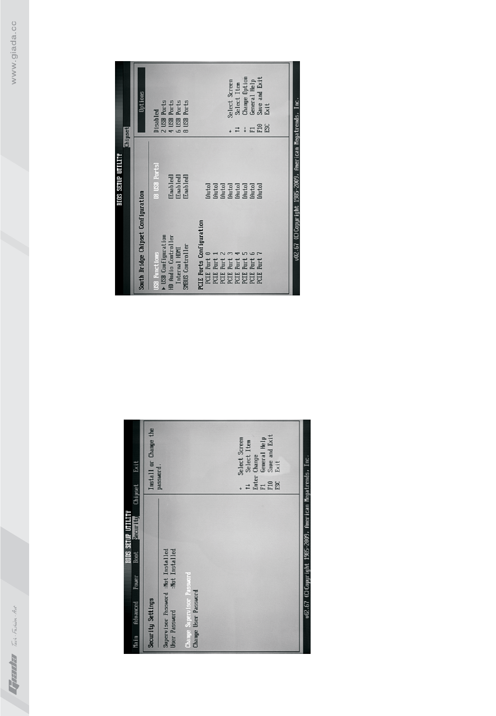
6. Security Setup
If this function is selected, the following information will appear:
Enter New Password hhhhhh
Fig 3.9
Then, enter the password with not more than eight characters and press
<Enter>. BIOS will requires to enter the password again. Once you enter
it again, BIOS will save the set password.
Once the password item is enabled, you will be required to enter the
password each time before the system goes to the set program of BIOS.
The user can set this item through the Security Option in advanced BIOS
properties. If the item Security Option is set as System, the password will
be required to be entered before the system guides and goes to the set
program of BIOS. If set as Setup, the password will be required to be
entered only before the system goes to the set program of BIOS.
To delete the password, press <Enter> in the popped-up window that
requires to enter the password. Then, information for confirmation will
appear on the screen to allow you decide whether the password is disabled.
Once the password is disabled, you won't have to enter the password and
can enter the setup program directly when the system is restarted.
Boot Sector Virus Protection
This item is used for setting the alarm function in the case of virus attack in
IDE disk sector. If this item is set as Enable and some program wants to
write information in the sector, BIOS will display alarm information on the
screen and buzz.
34
33
7. Setup for Chipset
· NorthBridge Configuration
To set the north bridge chip.
· SouthBridge Configuration
To set the south bridge chip.
· RX780 Configuration
· USB Configuration
To set the USB device.
Fig 3.10
· USB Configuration
· Legacy USB Support
This item is used for enabling or disabling the supports for USB devices.
If the default value [Auto] is selected, the system will automatically
check whether USB device is available in its startup process. If USB
device is available, USB controller will be activated. If not, not activated.
If you set this item as [Disabled], the USB controller inside the system
will be in OFF state, regardless of whether USB device is available.
The options are [Disabled], [Enabled] and [Auto].
· USB2.0 Controller Mode
This item is used for setting the transfer rate mode of USB 2.0 device.
The two options were HiSpeed (480 Mbps) and Full Speed (12 Mbps)
mode.
Fig 3.11
36
35
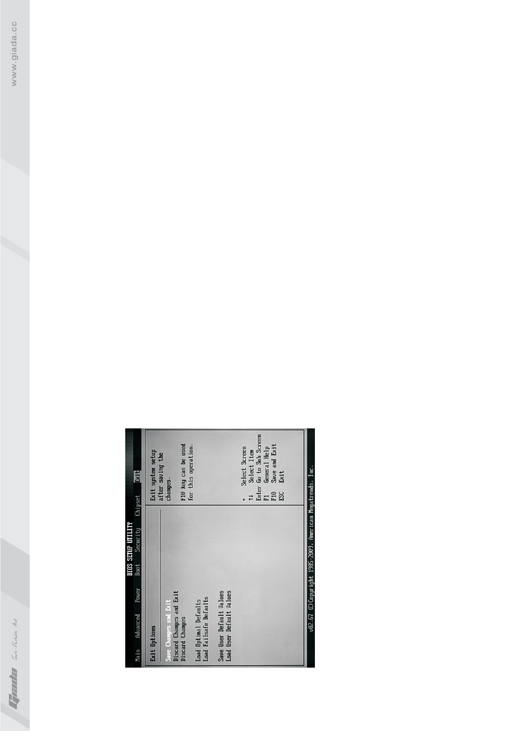
8. Exit
·
The exit options include load optimal defaults/load failsafe defaults
value/discard changes/discard changes and exit.
Exit Options
Fig 3.12
· Load failsafe defaults /optimal defaults
These two items can allow the user to restore all BIOS options to the
failsafe defaults and optimal defaults. The optimal defaults are set to
optimize the performance of the motherboard. The failsafe defaults are
conservative values for the system.
If you enter OK and press Enter, all set values will be saved to CMOS
SRAM and the system will exit from the BIOS setup program. If you don't
want to save, you can press Cancel or Esc to return to the main menu.
· Discard Changes and Exit
If you enter OK and press Enter, the system will exit from the BIOS
setup program. If press Cancel or ESC, return to the main menu.
· Discard Changes
If you enter OK and press Enter, the system will discard the changes.
If press Cancel or Esc, return to the main menu.
38
37
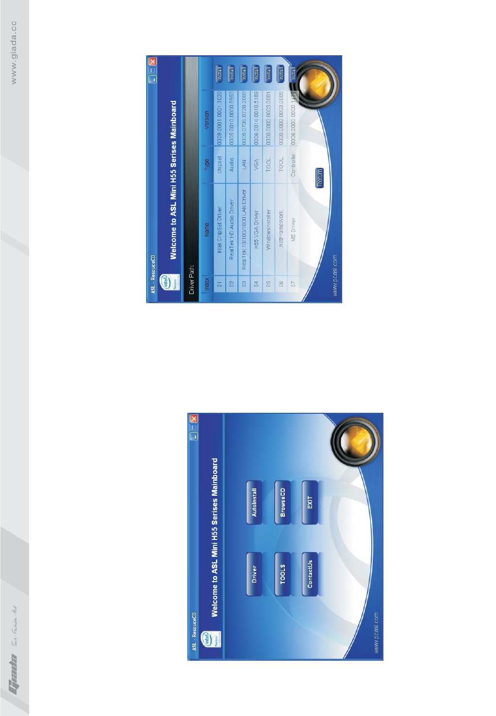
IV. Software installation
1. Install driver for motherboard
After you complete the installation of the operating system, you should
then install the driver for the motherboard. To this end, put the disk into
the CD-ROM. The interface as shown in Fig. 4.1 will appear.
Fig. 4.1
Fig. 4.2
In Fig 4.1, click "Driver ", another UI appears as shown in Fig 4.2.
40
39
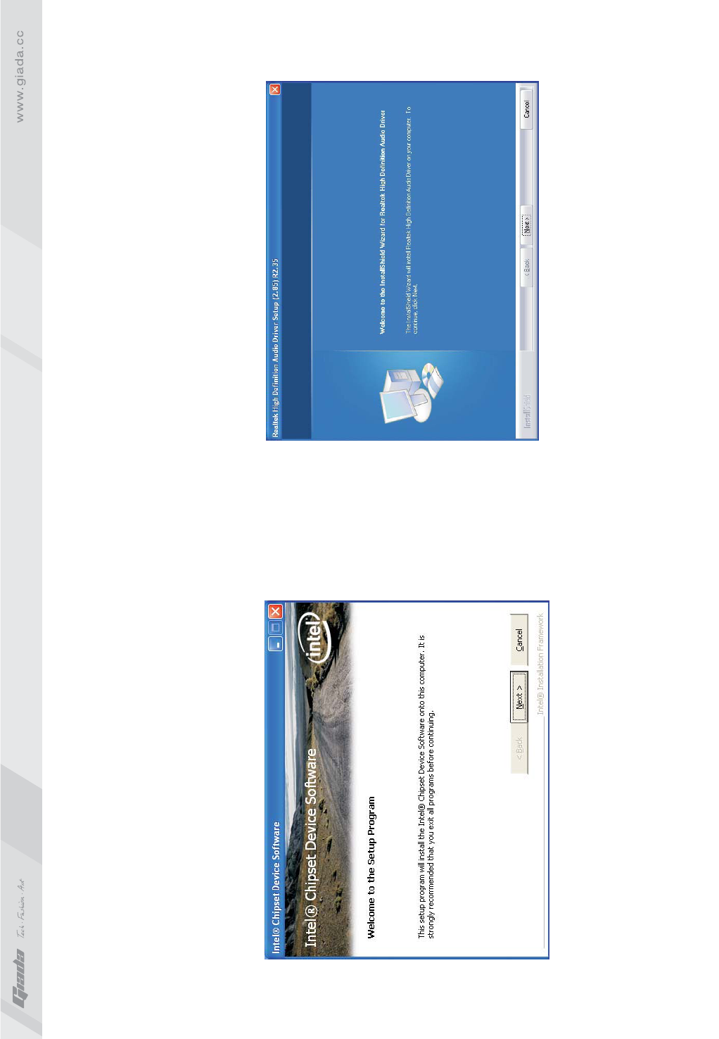
1.1. Installing driver for Chipset
After you click “Install” behind the “Intel Chipset driver” in the interface
of Fig. 4.2, a dialog box as shown in Fig. 4.3 will pop up. Then you can
click Next and wait till the driver is installed completely.
Fig. 4.3
1.2 Install Sound card driver
After you click “Install” behind the “Realtek HD audio driver” in the interface
of Fig. 4.2, a dialog box as shown in Fig. 4.4 will pop up. Then you can click
“Next” and wait till the driver is installed completely.
Fig. 4.4
4241
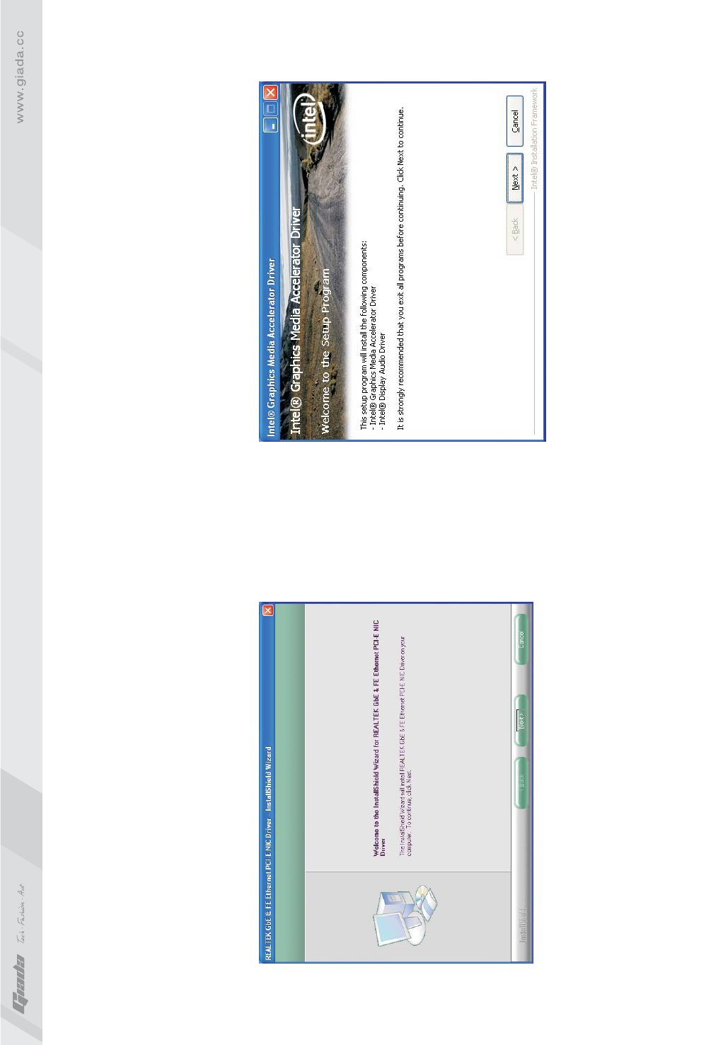
After you click “Install” behind the “Realtek 10/100/1000 LAN Driver” in the
interface of Fig. 4.2, a dialog box as shown in Fig. 4.5 will pop up. Then you
can click “Next” and wait till the driver is installed completely.
1.3 Installing driver for on-board LAN chip
Fig. 4.5
To install the driver for graphic card, you can click “Install” behind “H55 VGA
Driver” in the interface of Fig. 4.2, complete the installation by following the
indications in the popped-up dialog boxes, and then restart the computer.
1.4 Installing driver for graphic card
Fig. 4.6
44
43
2. HD-AUDIO sound card setup
For Windows XP SP2:
installed, as shown in Fig. 4.7.
After the initial installation of the driver, the default state of microphone
is mute. You need to turn it on manually, as shown in Fig. 4.8 and 4.9.
·
The control panel of the audio adapter will appear after the driver is
Fig. 4.7
Fig. 4.8
Fig. 4.9
46
45
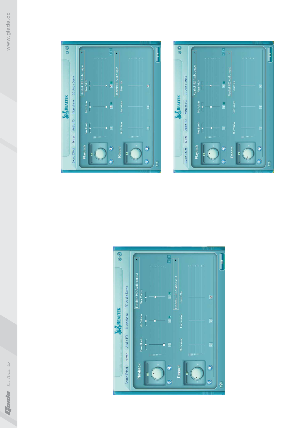
· For Windows Vista:
After the driver for the audio adapter is stalled, you can click the Audio
Manager at the lower right corner. The initial interface will pop up, as
shown in Fig. 4.10 and 4.11.
Fig. 4.10
Fig. 4.11
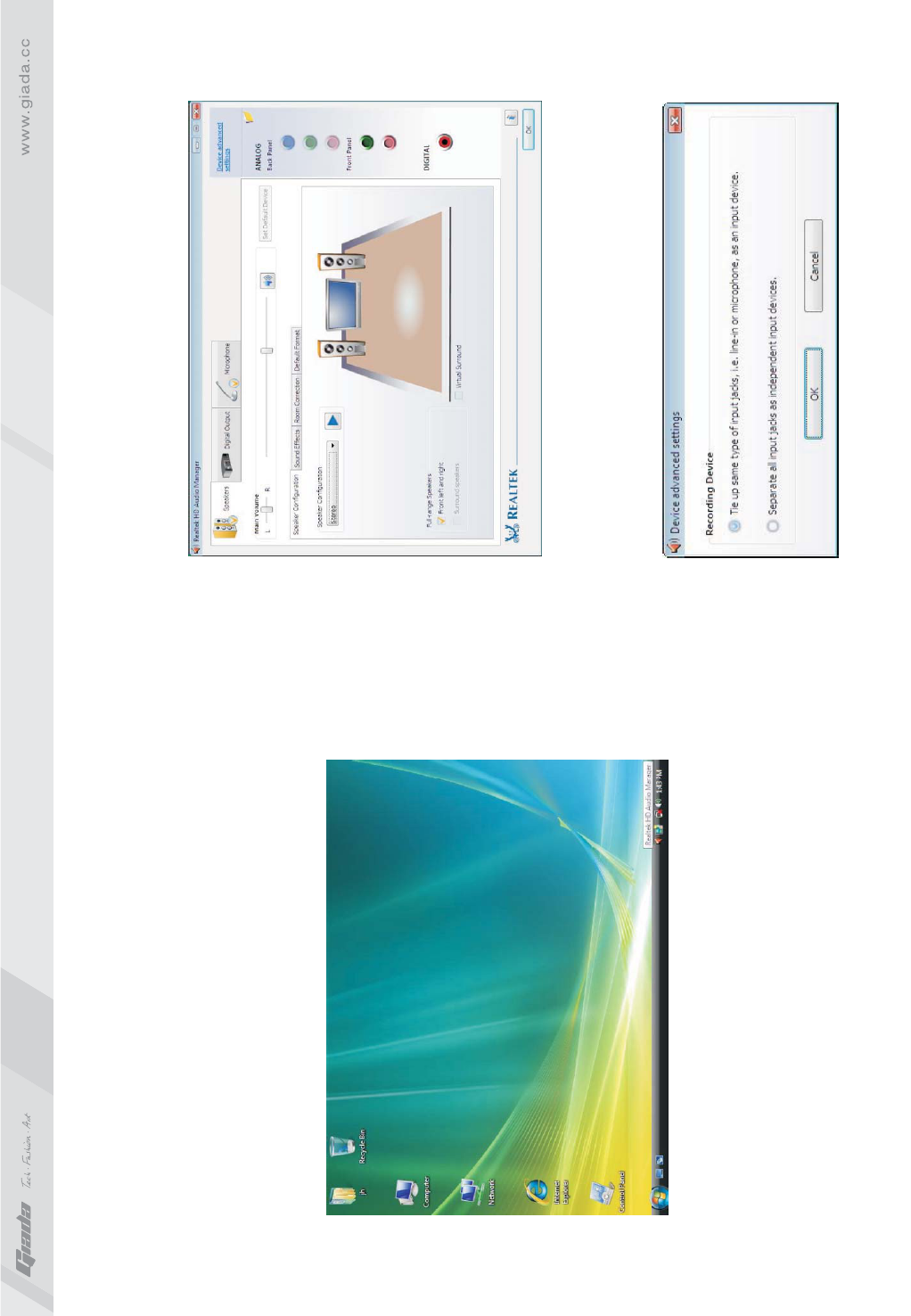
Click the right upper part of the control interfaceAdvanced Setup for
Device, the interface shown in Fig. 4.12 will pop up. Then select
“separate all input jacks as independent input devices”.
Fig. 4.12
4847
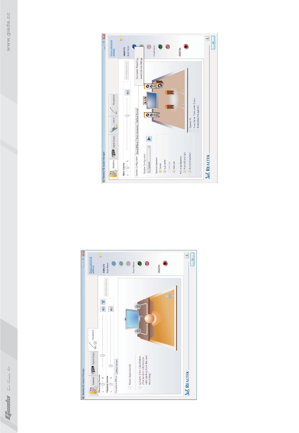
Click OK, and the controlling interface will turn to one shown in Fig. 4.13.
If a MIC is used, please select the corresponding front or rear mode and
set the device as default. In the above interface, you can adjust the
volume for recording and the playing volume for the MIC.
Fig. 4.13
Fig. 4.14
If you need to set the output of multi-channel, you should right click the
mouse at the corresponding output interface. A dialog box will pop up,
as shown in Fig. 4.14.
49
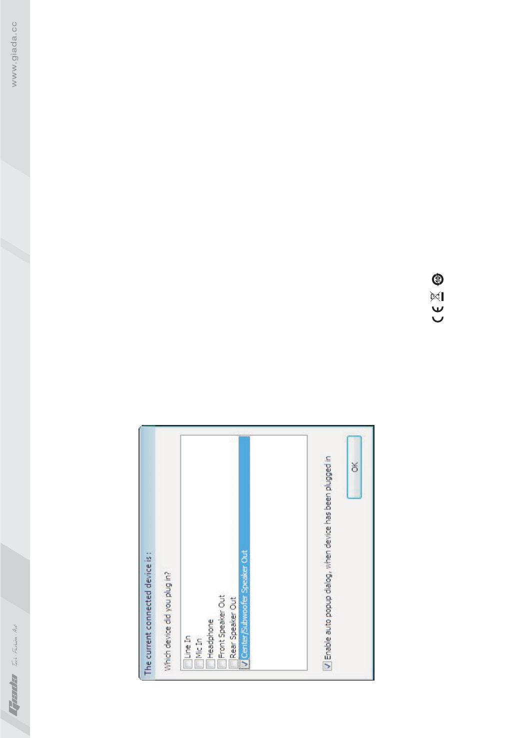
Select Redistribution of Connectors. Then an interface will pop up, as
shown in Fig. 4.15. After that, set the corresponding output.
Fig. 4.15
Changes or modifications not expressly approved by the party
responsible for compliance could void the user's authority to
operate the equipment
NOTE: This equipment has been tested and found to comply with
the limits for a Class B digital device, pursuant to Part 15 of the
FCC Rules. These limits are designed to provide reasonable
protection against harmful interference in a residential installation.
This equipment generates, uses and can radiate radio frequency
energy and, if not installed and used in accordance with the
instructions, may cause harmful interference to radio
communications. However, there is no guarantee that interference
will not occur in a particular installation. If this equipment does
cause harmful interference to radio or television reception, which
can be determined by turning the equipment off and on, the user is
encouraged to try to correct the interference by one or more of the
following measures:
-- Reorient or relocate the receiving antenna.
-- Increase the separation between the equipment and receiver.
-- Connect the equipment into an outlet on a circuit different from that to
which the receiver is connected.
-- Consult the dealer or an experienced radio/TV technician for help.
FCC ID:YIKMIH55
This device complies with Part 15 of the FCC Rules. Operation is subject to the following two conditions:
(1) this device may not cause harmful interference, and
(2) this device must accept any interference received, including interference that may cause undesired operation.
50