Jiangmen Dascom Computer Peripherals TD2100 Thermal Receipt Printer User Manual Tally Dascom DT 210 230
Jiangmen Dascom Computer Peripherals Co.,Ltd. Thermal Receipt Printer Tally Dascom DT 210 230
Users Manual

User Guide DT-210/230 Thermal Receipt Printer

Tally Dascom DT-210/230 User Guide V1.3
I
Important Safety Instructions (English)
Read the following instructions thoroughly before starting up your printer.
• The device and mains-socket must all times be easily accessible.
• Never carry out maintenance or repair work yourself. Always contact a qualified service
technician.
• Keep this user guide in a place which is easily accessible at all times.
• Place the printer on a solid and even base so that it cannot fall.
• Never place the printer in the vicinity of inflammable gas or explosive substances.
• Ensure the printer is connected to a socket with the correct voltage.
• Always disconnect the printer from the power before opening the device to perform
maintenance work or remedy errors.
• Do not expose the printer to high temperatures, direct sunlight or dust.
• Keep all liquids away from the printer.
• Protect the printer from shock, impact and vibration.
• Make sure that both the printer and the computer are switched off before connecting the data
cable.
• The print head will become very hot during printing; avoid contact with the print head after
printing has finished.
• Do not perform any operation or action in any way other than those provided in this manual.
When in doubt, contact your dealer or your customer support.

Tally Dascom DT-210/230 User Guide V1.3
II
About This Manual
This manual provides information to operators of the DT-210/230 to describe basic operations to enable safe
and correct use of the printer.
Symbols Description
The symbols in this manual are identified by their level of importance, as defined below. Read the following
carefully before handling the product.
CAUTION: Provides information that must be observed to prevent damage to the
equipment or loss of date.
NOTE: Advises you of information that is essential to complete a task.

Tally Dascom DT-210/230 User Guide V1.3
TABLE OF CONTENTS
ABOUT THIS MANUAL .................................................................................................................................. II
1 PRODUCT OVERVIEW ................................................................................................................................ 1
1.1 Features ............................................................................................................................................................... 1
1.2 Unpacking ............................................................................................................................................................ 3
1.3 Product Configurations ........................................................................................................................................ 4
1.4 Part Names and Functions ................................................................................................................................... 5
1.4.1 Power Switch ................................................................................................................................................. 6
1.4.2 Control Panel ................................................................................................................................................. 6
1.4.3 LED Indicators ............................................................................................................................................... 7
2 SETUP ....................................................................................................................................................... 8
2.1 Flow of Setup ....................................................................................................................................................... 8
2.2 Installing the Printer ............................................................................................................................................. 9
2.3 Changing the Paper Width ................................................................................................................................. 10
2.4 Attaching Power ................................................................................................................................................. 11
2.5 Adjusting the Paper Near-end Sensor ................................................................................................................ 12
2.6 Loading Roll Paper .............................................................................................................................................. 13
2.7 Installing Optional Kits ....................................................................................................................................... 15
3 INSTALLING DRIVER .................................................................................................................................. 16
3.1 Installation Driver for Ethernet and Wi-Fi Interface .......................................................................................... 18
3 CONNECTING TO COMPUTER .................................................................................................................... 23
3.1 For USB Interface ............................................................................................................................................... 24
3.2 For Cash Draw Interface ..................................................................................................................................... 24
3.3 For Serial Interface ............................................................................................................................................. 25
3.4 For Parallel Interface .......................................................................................................................................... 26
3.5 For Ethernet Interface ........................................................................................................................................ 26
3.6 For Wireless LAN Interface ................................................................................................................................ 30
3.6.1 Get IP Address ............................................................................................................................................. 32
3.6.2 Wlan Setup - AP mode ................................................................................................................................ 35
3.6.3 Wlan Setup - STA mode ................................................................................................................................37
3.6.4 Return to Factory Setting ............................................................................................................................ 38
3.7 Connecting to Bluetooth .................................................................................................................................... 39
3.7.1 Installing Bluetooth Adapter Driver ............................................................................................................ 39
3.7.2 Changing Printer Port .................................................................................................................................. 41
3.7.3 Changing Baud Rate of the Printer .............................................................................................................. 44
4 SETTING/CHECKING MODES ...................................................................................................................... 45
4.1 Self-test Mode .................................................................................................................................................... 45
4.2 Hexadecimal Dumping Mode ..............................................................................................................................47
5 SETTING DIP SWITCHES ............................................................................................................................. 48
5.1 Setting Procedure ............................................................................................................................................... 48
5.2 For Serial Interface (RS-232C) ............................................................................................................................ 49
5.3 For Parallel and USB2.0 Interface ....................................................................................................................... 50
5.4 Selecting the Print Density ................................................................................................................................. 51

Tally Dascom DT-210/230 User Guide V1.3
5.5 Auto Cutter Enable/Disable Selection ................................................................................................................ 51
6 TROUBLESHOOTING .................................................................................................................................. 52
6.1 Error Status ........................................................................................................................................................ 52
6.2 Removing Jammed Paper ................................................................................................................................... 53
6.3 Cleaning Thermal Head ...................................................................................................................................... 54
7 SPECIFICATIONS ........................................................................................................................................ 55
7.1 Printer Specification ........................................................................................................................................... 55
7.2 External Dimension and Mass .............................................................................................................................57
7.3 Interfaces ........................................................................................................................................................... 58
7.3.1 USB interface ............................................................................................................................................... 58
7.3.2 Cash Drawer interface ................................................................................................................................. 58
7.3.3 Serial interface ............................................................................................................................................ 59
7.3.4 Parallel interface ......................................................................................................................................... 59
7.3.5 Ethernet interface ....................................................................................................................................... 61
7.3.6 Wi-Fi interface ............................................................................................................................................ 61
7.4 Power Adapter ................................................................................................................................................... 61
7.5 Paper Specification ............................................................................................................................................ 62
7.5.1 Printable Area ............................................................................................................................................. 62
7.5.2 Printing and Cutting Positions ..................................................................................................................... 64
8 CHARACTER CODE PAGES .......................................................................................................................... 65
8.1 Common to All Pages (International Character Set: USA) .................................................................................. 65
8.2 International Character Sets .............................................................................................................................. 66
8.3 [User-defined page] ........................................................................................................................................... 67
8.4 [PC437: USA, Standard Europe] ......................................................................................................................... 68
8.5 [PC850: Multilingual] ......................................................................................................................................... 69
8.6 [PC852: Latin2] ....................................................................................................................................................70
8.7 [PC858: Euro] ..................................................................................................................................................... 71
8.8 [PC860: Portuguese] ...........................................................................................................................................72
8.9 [PC863: Canadian-French] ................................................................................................................................. 73
8.10 [PC865: Nordic] .................................................................................................................................................74
8.11 [PC866: Cyrillic #2] ........................................................................................................................................... 75
8.12 [KU42: Thai] ......................................................................................................................................................76
8.13 [TIS11: Thai] ..................................................................................................................................................... 77
8.14 [TIS18: Thai] ..................................................................................................................................................... 78
8.15 [PC720: Arabic] ................................................................................................................................................. 79
8.16 [PC864: Arabic] ................................................................................................................................................ 80
8.17 [WPC1256: Arabic] ........................................................................................................................................... 81
9 PRINTING CONTROL COMMAND SETS ........................................................................................................ 82
FCC STATEMENT ........................................................................................................................................... 86
DASCOM REPRESENTATIVES ......................................................................................................................... 87

Tally Dascom DT-210/230 User Guide V1.3
1
1 PRODUCT OVERVIEW
Tally Dascom’s DT-210/230 offers high-speed label printing for a wide range of terminal equipment
including data, POS, and kitchen terminals. With extensive features, they can be used in a wide range
of applications such as food service, retail and grocery.
With an internal memory large enough to store logos, footers, custom fonts, keywords and
downloading custom applications, this unit has it all. The DT-210/230 can be desktop or
wall-mounted and comes standard with USB interface, RS-232 serial, Centronics parallel, Ethernet,
Wi-Fi or Bluetooth interfaces. Printer drivers included are: Windows XP (32 and 64 bit), Windows
Vista (32 and 64 bit), Java POS, OPOS, and Linux.
1.1 Features
Printing
• High speed printing (260 mm/s maximum).
• Versatile roll capacity with ability to use 80mm, and 58mm wide paper rolls.
• Can use paper roll with a maximum of 83mm diameter.
• 2-color printing is supported (When specified paper is used).
• Equipped with a fast and quiet cutter.
Handling
• Compact design, can be installed anywhere.
• Drop-in paper roll mechanism facilitating easy paper handling and head cleaning.
• Drip-proof design.
Software
• Command protocol is based on the ESC/POS Proprietary Command System.
• OPOS ADK, OPOS ADK for .NET, JavaPOS ADK, Linux, and Windows printer drivers are available.
• Barcode and 2D barcode printing supported.
• Various layouts are possible by using page mode.
• Buzzer reminder after each printout.
• Paper-saving function is supported.

Tally Dascom DT-210/230 User Guide V1.3
2
• The DT-210/230 is ENERGY STAR qualified. (Some configurations may be exempted, depending on their
components.)
Others
• Wide range of connectivity. The USB interface is standard interface. Serial/parallel/Ethernet/ Wi-Fi/
Bluetooth are optional interfaces. Various interface choices suit all needs.
• Built-in USB interface is also available for all interface models.
• The DT-210/230 Software & Documents Disc (drivers, utility, and manuals).
• Printer status and errors indicated by 3 LEDs and a buzzer.
Tally Dascom DT-210/230 User Guide V1.3
3
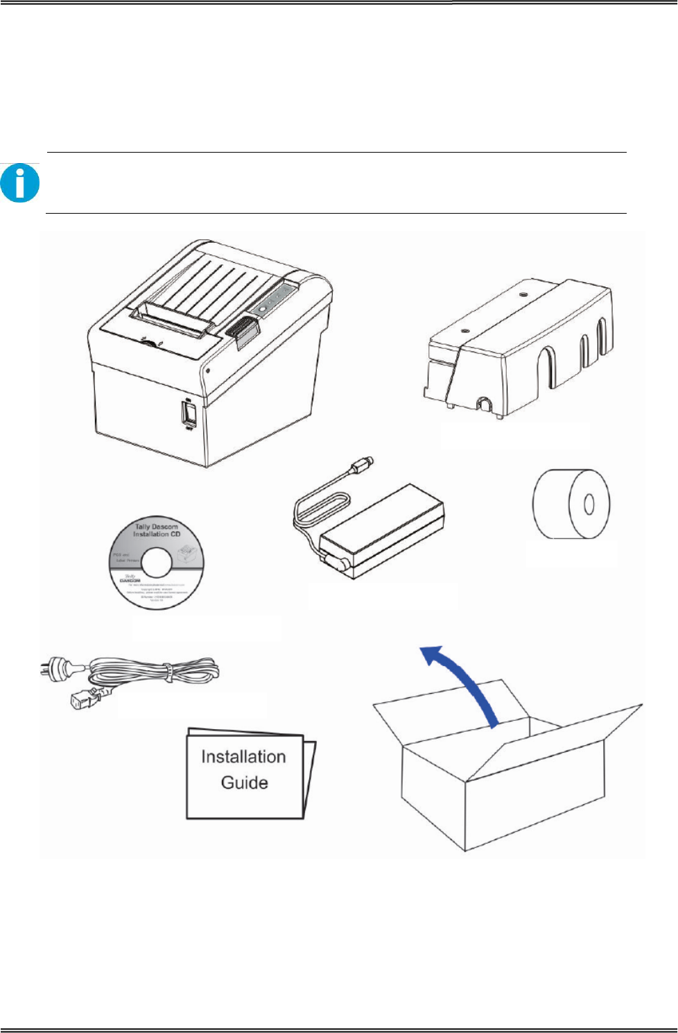
1.2 Unpacking
Open the packaging, lift the printer out of the cardboard box and remove the remaining packaging
material. Check the printer for any visible transport damage and missing items. If you find any
transport damage or any accessories are missing, please contact your dealer for assistance.
Please keep the packaging material for future transportation.
The shipping list varies with different customized order requirements.
Interface Cable Cover
Power Cord
CD
Roll Paper
Power Adaptor
Tally Dascom DT-210/230 User Guide V1.3
4
Shipping List
Items QTY. Remarks
Printer 1 unit
Interface Cable Cover 1 piece
Power Adapter 1 piece
Power Cord 1 piece
Roll Paper -Test 1 piece
Graphic Installation Guide 1 piece
CD 1 piece including user guide, graphic installation
guide, Driver and demo tool
1.3 Product Configurations
There are two models in this series.
• DM-310: without auto cutter
• DM-330: with auto cutter
Interface Types
• USB model
• Serial UB + built-in USB interface model
• Parallel UB + built-in USB interface model
• Ethernet UB
• Wireless LAN UB
• Bluetooth UB
Tally Dascom DT-210/230 User Guide V1.3
5
Model
Power
Adapter Interfaces Power
Cord Paper Cut Sensor
100-240 USB Cashbox PAR SER ETH Wi-Fi Fiscal EN/UK/EU Cutter Tear
Bar
Black
Mark
DT-210 √ √ √ O O O O O √ N √ O
DT-230 √ √ √ O O O O O √ √ √ O
Remarks: “√” indicates standard configuration, “O” indicates optional configuration.
PAR=Parallel interface; SER= Serial interface; ETH=Ethernet interface.
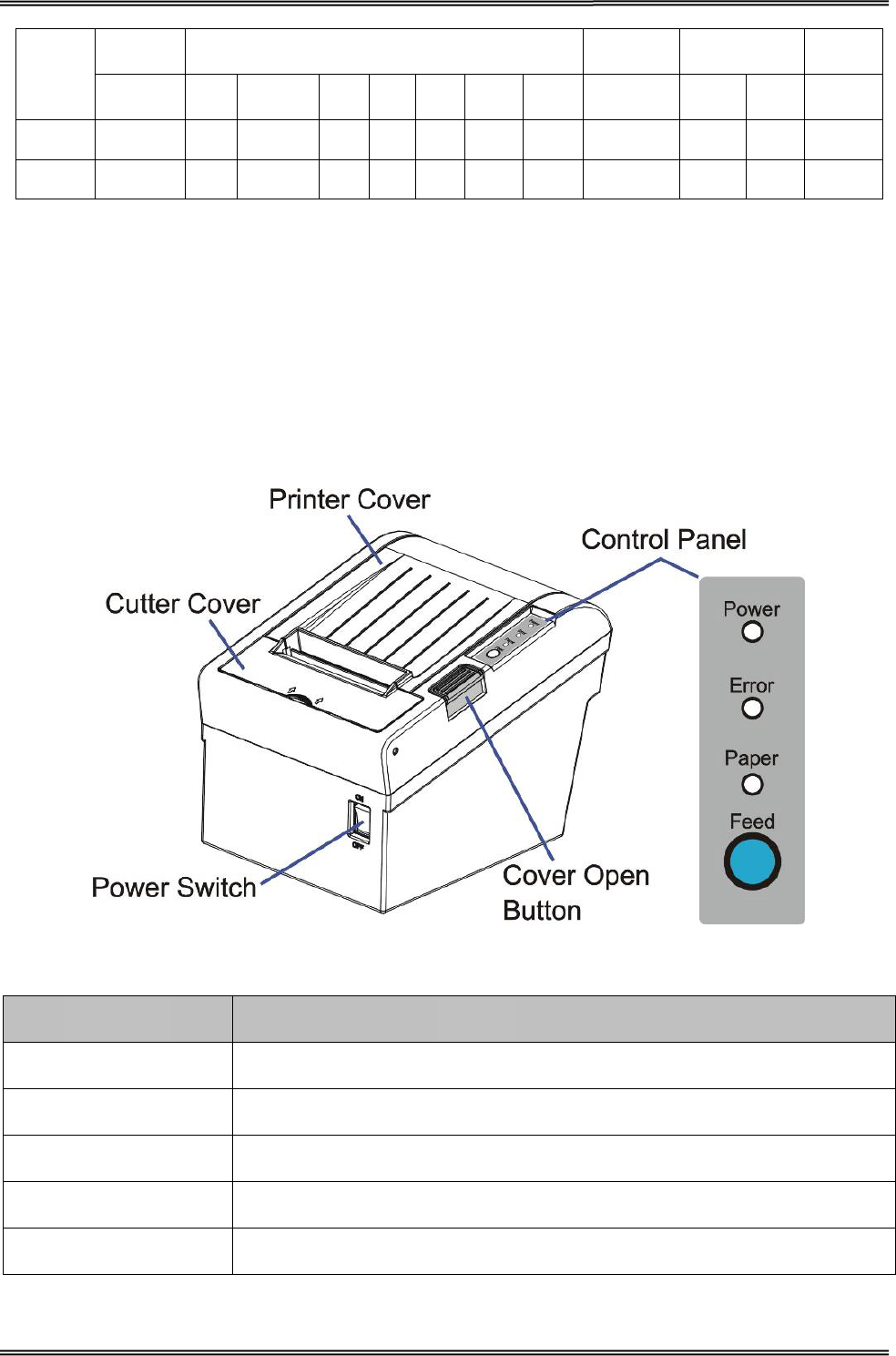
1.4 Part Names and Functions
Printer components and functions are shown as below:
Component Function
Printer Cover Open the cover when loading roll paper.
Control Panel Shows printer status.
Power Switch To power printer ON or OFF.
Cutter Cover To protect the auto-cutter and to clear paper jam at cutter.
Cover Open Button Press down to open the Printer Cover
Tally Dascom DT-210/230 User Guide V1.3
6
1.4.1 Power Switch
Turn the printer on or off. The marks on the switch: (O: OFF / | : ON)
Before turning on the printer, be sure to check that the AC adapter is connected to
the power supply.
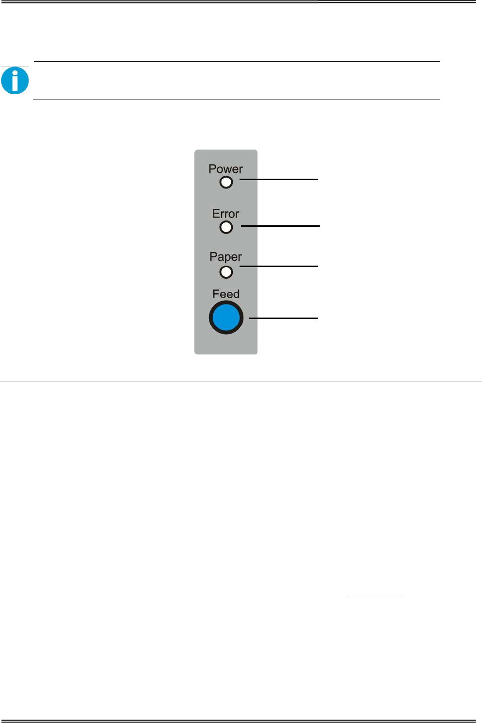
1.4.2 Control Panel
Power LED
Error LED
Paper LED
Feed key
LEDs
Power LED (green)
• Lights when the power supply is on.
• Goes out when the power supply is turned off.
Error LED
Lights or flashes when the printer is offline.
• Lights after the power is turned on or after a reset (offline). Automatically goes out after a while
to indicate that the printer is ready.
• Lights when the end of the roll paper is detected, and when printing has stopped (offline). If this
happens, replace the roll paper.
• Flashes when an error occurs. (For details about the flash code, see “Error Status” on page 52.)
• Goes out during regular operation (online).
Paper LED
• Lights when there is no more roll paper or there is little remaining.
• Off when there is a sufficient amount of roll paper remaining.
• Flashed when a self-test is in progress.

Tally Dascom DT-210/230 User Guide V1.3
7
Feed Key
Pressing this key once feeds the roll paper by one line. Holding this button down feeds the roll paper
continuously.
1.4.3 LED Indicators
Description POWER ERROR PAPER BEEPER
Printer Cover is open On On On
Short beep for twice and long beep for
once
Roll paper is sufficient On Off Off No beep
Roll paper end On On On Short beep for three times
Roll paper near end On Off On No beep
Tally Dascom DT-210/230 User Guide V1.3
8
2 SETUP
This chapter describes the setup and installation of the product and peripherals.
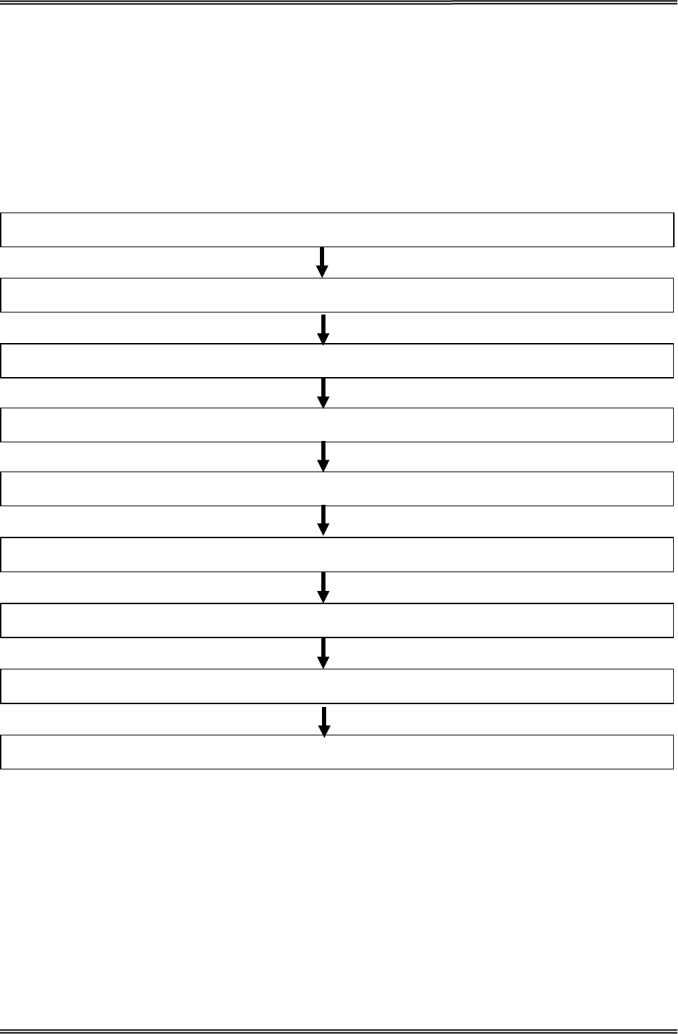
2.1 Flow of Setup
This chapter consists of the following sections along with the setup flow of the product and
peripherals.
9. Connecting the Cash Drawer (page 24)
8. Connecting the Printer to the Host Computer (page 23)
7. Installing Driver (page 16)
6. Printing Self-test (page45)
5. Adjusting the Paper Near-End Sensor (page 12)
4. Attaching Power (page 11)
3. Setting the Dip Switches (page 48)
2. Changing the Paper Width (page 10)
1. Installing the Printer (page 9 )
Tally Dascom DT-210/230 User Guide V1.3
9
2.2 Installing the Printer
You can install this printer horizontally. With an optional mounting plate (P/N: 99501), you can also
attach the printer to a wall.
Important Notes on Horizontal Installation:
• The printer must be installed horizontally on a flat surface (not tilted).
• Do not place the printer in dusty locations.
• Do not knock or strike the printer. This may cause defective print.
• Do not catch cables or place foreign matter under the printer.
Important Notes on Horizontal Installation:
You need to perform the follow tasks to install the printer on a wall. For more details, turn to
Mounting Plate installation part on page 16.
• Installing the roll-paper stoppers.
• Changing the location of the roll paper near-end sensor.
• Attaching the connector cover.
• Attaching the wall mounting plate (P/N: 99501).
Be sure to attach the connector cover when you install the printer on a wall using
the wall mounting plate.
Tally Dascom DT-210/230 User Guide V1.3
10
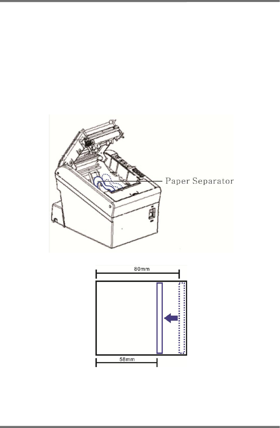
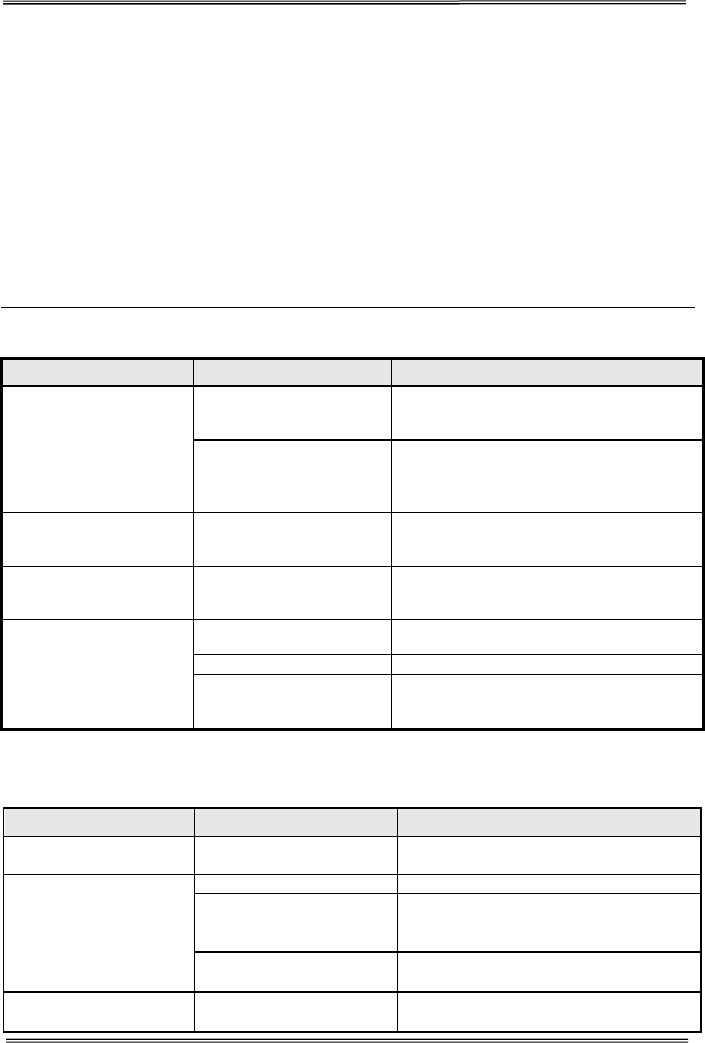
2.3 Changing the Paper Width
The printer is initially set to print on 80 mm width paper and you can change the printer to print on
58 mm width paper by installing the roll paper guide and changing the paper width setting with
customized value.
Follow the steps below to install the roll paper guide.
1. Open the roll paper cover.
2. Hold the paper separator and carefully pull it out in the direction of arrow.
3. Move paper separator from right side to the specified position near the middle of paper holder,
and carefully insert it into the specified position.
Tally Dascom DT-210/230 User Guide V1.3
11
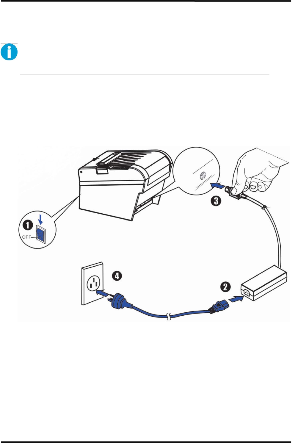
2.4 Attaching Power
Checking the voltage of the power adapter
Before you connect the power adapter to the power socket check if the voltage is
correct. If you connect the power adapter to power with incorrect voltage this may
result in electrical damage to adapter and printer.
1. Make sure the printer and the computer are powered off.
2. Connect the power cord to the power adapter.
3. Connect the power adapter to the power supply interface at the rear of the printer.
4. Ensure the power cord is securely connected. Connect the power cord plug to a
mains socket on the wall.
Power on and power off
• Press the power switch to the “I” position to turn on the printer.
Upon power-on, the Power LED indicator light up.
• Press the power switch to the “O” position to turn off the printer.
Tally Dascom DT-210/230 User Guide V1.3
12
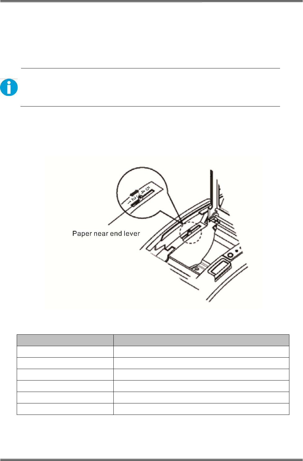
2.5 Adjusting the Paper Near-end Sensor
Below are two situations where a paper near-end sensor adjustment is required.
• To adjust the detection position to suit the diameter of the roll paper core used.
• To adjust the detection position of remaining amount of paper.
CAUTION!
Since roll paper cores vary slightly in shape, depending on paper roll design and
manufacturing tolerances, it is impossible to detect the remaining paper exactly.
Follow the steps below to adjust the roll paper near-end detector.
1. Open the roll paper cover, and remove the roll paper.
2. You will see a black lever inside as shown below.
3. Adjust the lever according to your need.
Adjustments position Remaining amount of paper (outer diameter: mm)
1 (Minimum) Approx. 26 {1.02”}
2 Approx. 27 {1.06”}
3 Approx. 28 {1.10”}
4 Approx. 30 {1.18”}
5 Approx. 32 {1.26”}
6 (Maximum) Approx. 33 {1.30”}
Tally Dascom DT-210/230 User Guide V1.3
13
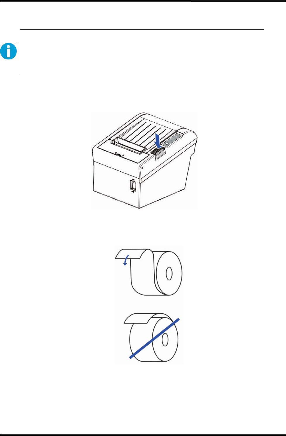
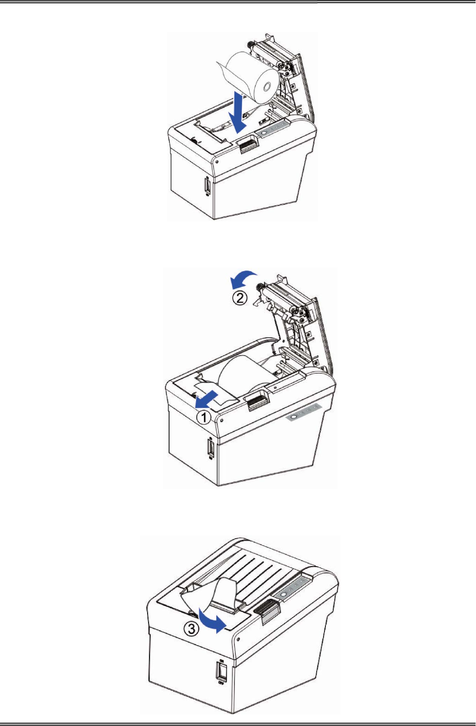
2.6 Loading Roll Paper
WARNING!
When opening the cover, take care not to touch the print head or cutter blade.
Otherwise, burning or injury of hand may result.
1. Press the cover open button to open the cover.
2. Remove the used roll paper core, if any.
3. Insert the paper roll with its print area facing down as shown in the figure.
Tally Dascom DT-210/230 User Guide V1.3
14
4. Install the media in the correct direction.
5. Pull out some roll paper, and close the cover.
6. Tear off the paper with the manual cutter till you hear a click sound.
Tally Dascom DT-210/230 User Guide V1.3
15
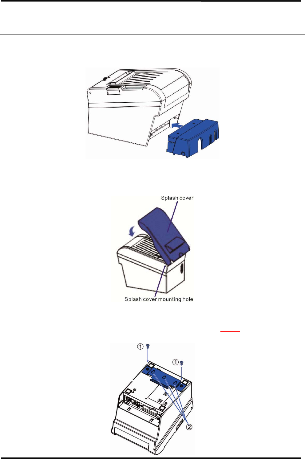
2.7 Installing Optional Kits
Interface Cover
Adjust the relative positions between interface cover and printer as shown below, and push the
interface cover as arrow shows below.
Splash Cover (optional kit)
Slip the fixed hooks on both sides of splash cover into the mounting hole on the printer, and close the
splash cover.
Mounting Plate (optional kit)
1. Mount the plate on the lower housing of the printer with screws.
2. Align the positioning holes of the hanging plate and plug into the fixed screws on the wall.
Tally Dascom DT-210/230 User Guide V1.3
16
3 INSTALLING DRIVER
Installing the Windows Driver (Compatible with Windows)
Switch off the printer before running the printer driver setup.
Your printer CD-ROM comes with Windows drivers. Go to the related folder and run the driver setup
installer.
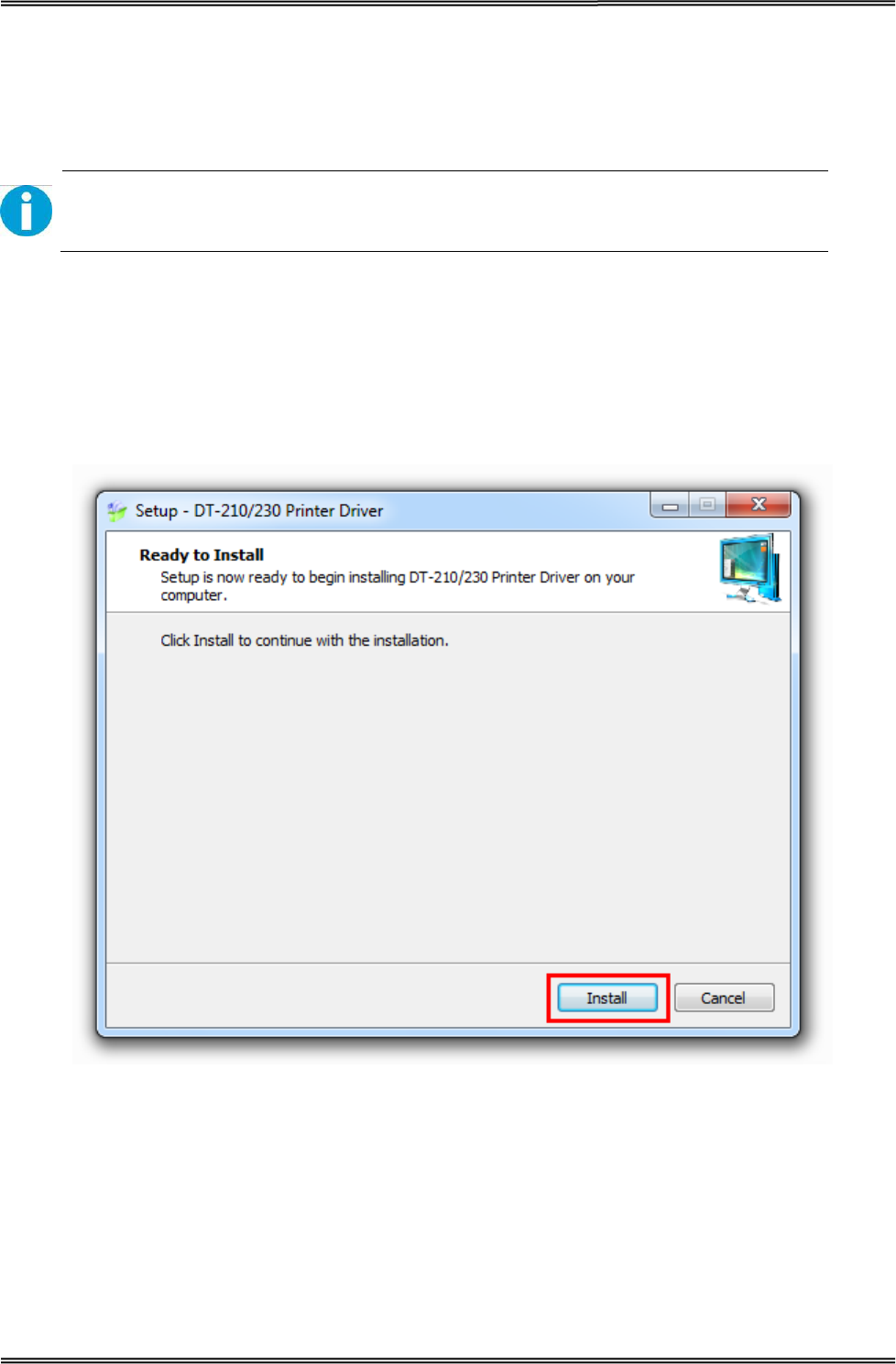
1. Double click the driver. You will see the screen as below. Click “Install” to continue.
Tally Dascom DT-210/230 User Guide V1.3
17
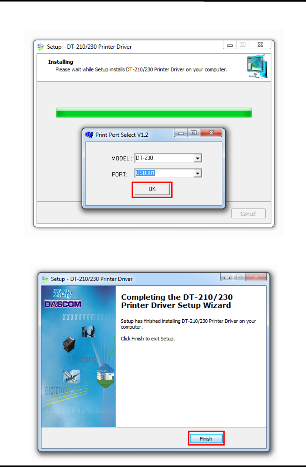
2. Choose the desired port to use, after selecting the “Port” option (USB001 for USB port, com1 for
serial port and LPT1 for parallel port), click “Next” to continue.
3. Click “Finish” to finish the installation process successfully.
Tally Dascom DT-210/230 User Guide V1.3
18
3.1 Installation Driver for Ethernet and Wi-Fi Interface
1. Install the printer driver as USB installation.
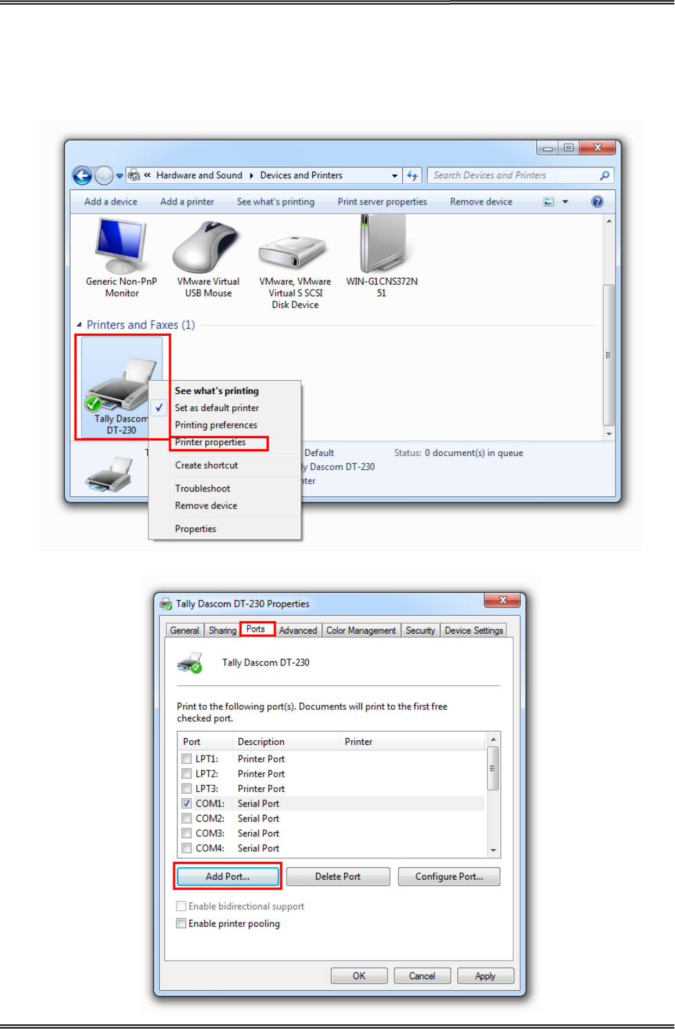
2. Click “Start”→ “Devices and Printers”, right click on the DT -230 Printer Driver, and then click
“Printer Properties”.
3. Then you will see the screen as below. Click “Ports” → “Add Port”.
Tally Dascom DT-210/230 User Guide V1.3
19
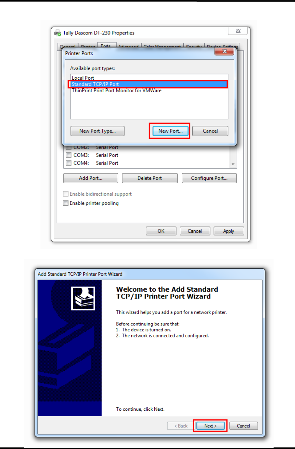
4. Select “Standard TCP/IP Port”, and click “New Port”.
5. You will see the screen as below, click “Next” to continue.

Tally Dascom DT-210/230 User Guide V1.3
20
6. Complete the “Printer Name or IP Address” and “Port Name”.
7. Click “Next” to access the screen as below.
Tally Dascom DT-210/230 User Guide V1.3
21
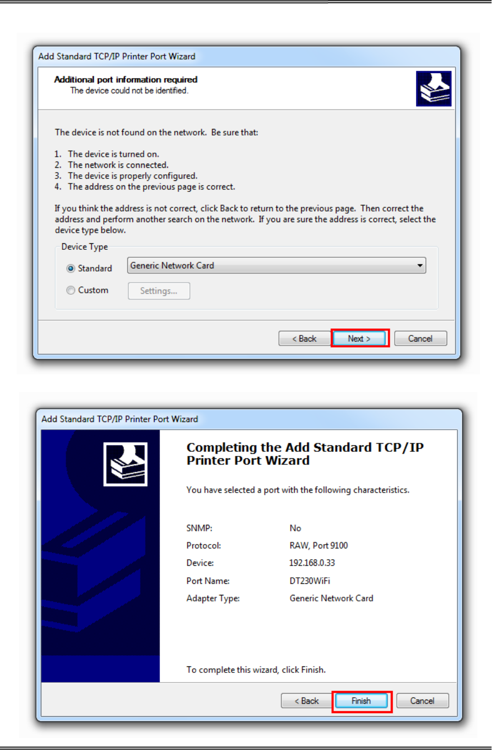
8. And then you will see the screen as below, click “Next” to continue.
9. Click “Finish” to complete the printer driver installation.
Tally Dascom DT-210/230 User Guide V1.3
22
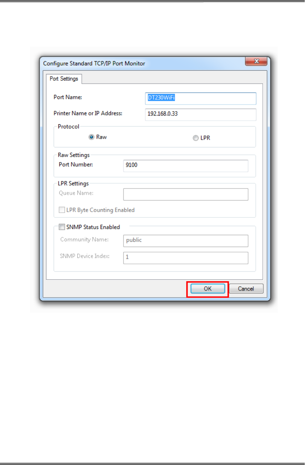
10. Click “Start”→ “Devices and Printers”, right click on the DT-230 Printer Driver, and then click
“Printer Properties”. Then click “Ports” → “Configure Port”, finish the setup parameter in the
screen as below. Click “OK” to finish the setup.

Tally Dascom DT-210/230 User Guide V1.3
23
3 CONNECTING TO COMPUTER
NOTE!
Be sure to install the driver before connecting the printer to the host computer.
Before installing, disconnect the Power Unit from the printer (as well as turning the power switch
off). Even when the power switch is off, voltage is still present at some points on the circuit board.
Changing components while the power unit is connected can cause damage to the interface board
and the printer.
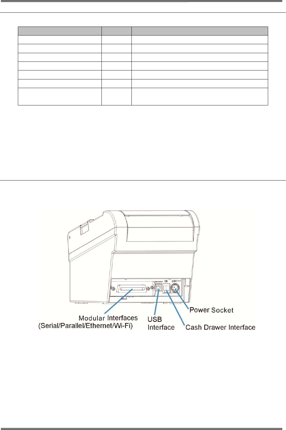
Component Function
Power Socket Connects power cord to the printer.
Cash Drawer Interface Connects Cash Drawer interface cable from the cash drawer.
USB Interface Connects USB interface cable from the host.
Modular Interface
Connects optional interface (Serial I/F, Parallel I/F, Ethernet I/F or Wi-Fi
I/F) from the host.
Tally Dascom DT-210/230 User Guide V1.3
24
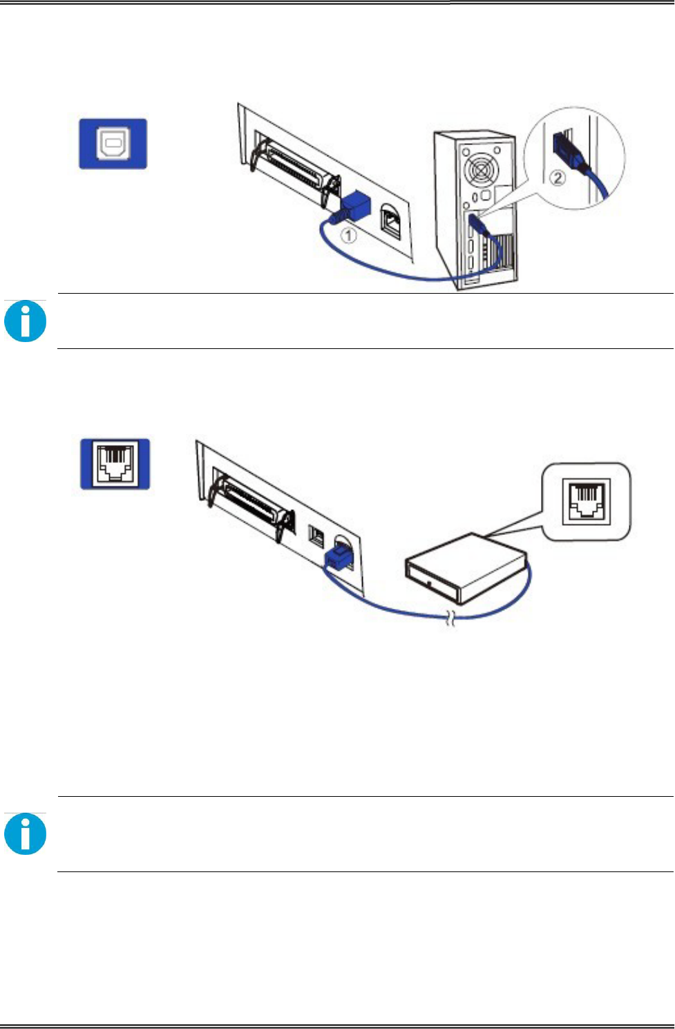
3.1 For USB Interface
CAUTION!
Be careful not to insert the USB interface cable into the cash drawer kick-out connector.
3.2 For Cash Draw Interface
1. Confirm that the power switch is OFF.
2. Confirm the top and button of the cash drawer cable connector and insert it into
the cash drawer kick-out connector at the back of the printer.
3. Screw the cash drawer’s ground wire to the body of the printer.
CAUTION!
DO NOT connect any other device than the specified cash drawer to the cash drawer
kick-out connector. (Do NOT connect a telephone line either)
Tally Dascom DT-210/230 User Guide V1.3
25
3.3 For Serial Interface
WARNING!
Be sure to turn off the power supply for both the printer and host computer before
connecting the cables.
1. Insert the interface cable connector firmly into the interface connector on the
connector panel.
2. When using the connectors equipped with screws, tighten them to secure the
connectors firmly.
3. When using interface cables equipped with a grounding line, attach the ground
line to the screw hole marked “FG” on the printer.
4. Connect the other end of the interface cable to the host computer.
Tally Dascom DT-210/230 User Guide V1.3
26
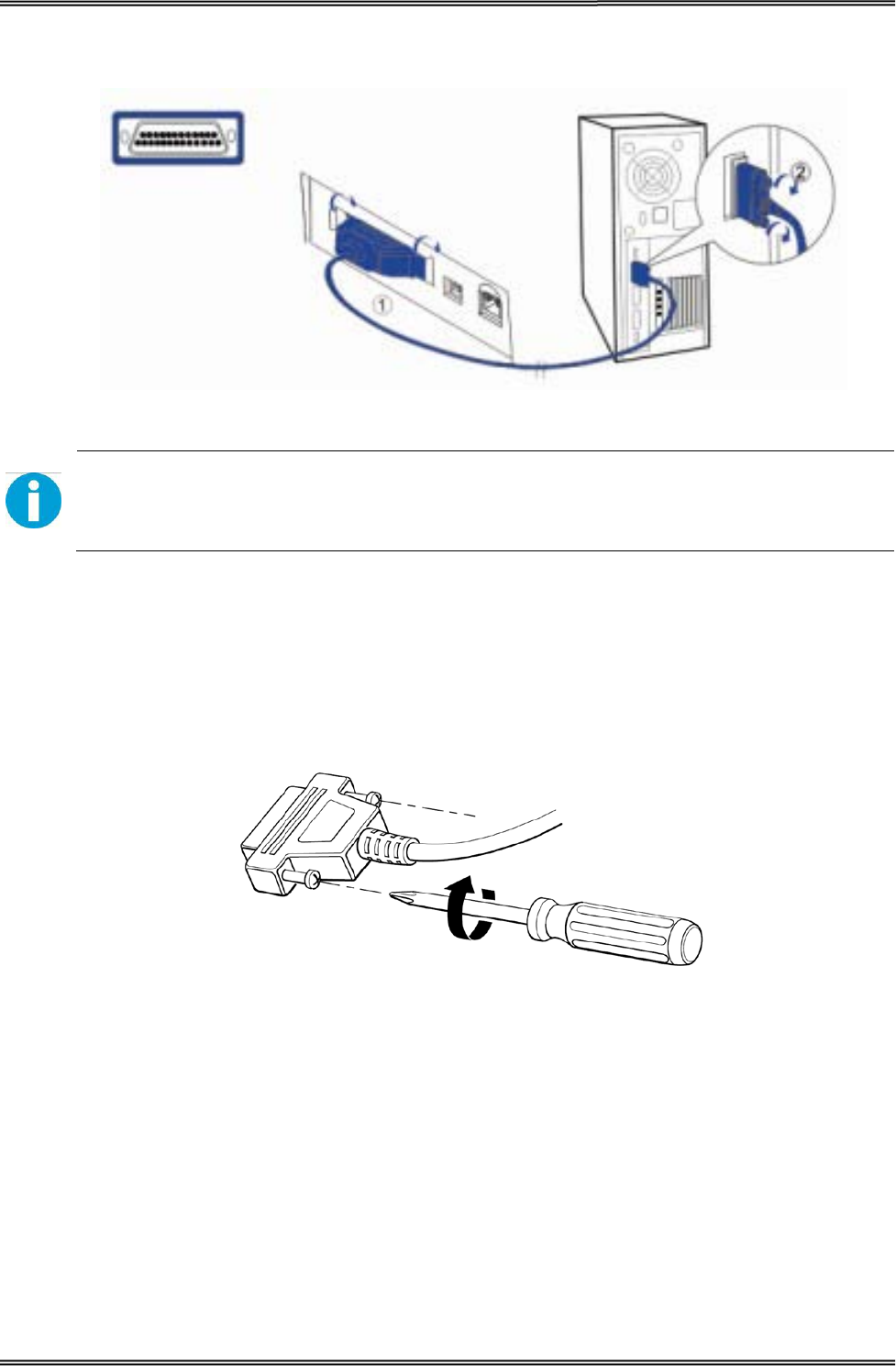
3.4 For Parallel Interface
1. Insert the interface cable connector firmly into the interface connector on the
connector panel.
2. Press down the clips on either side of the connector to lock it in place.
3. When using interface cables equipped with a grounding line, attach the ground
line to the screw hole marked “FG” on the printer.
4. Connect the other end of the interface cable to the host computer.
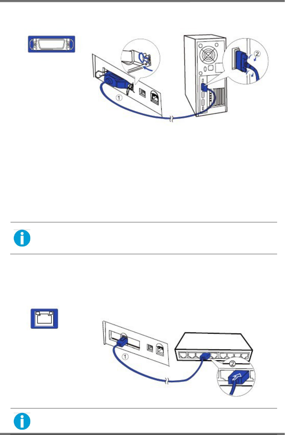
3.5 For Ethernet Interface
NOTE!
Before installation, make you have installed the driver and the driver for Ethernet
interface (see Installing Driver on page 17)
Connect the printer to a network by a LAN cable via a hub.
Connect a 10/100BASE-T cable to the 10/100BASE-T LAN connector by pressing firmly until the
connector clicks into place.
When using the Ethernet interface, the network configuration is required. Make the settings on the
setup page.
• When LAN cables are installed outdoors, make sure devices without proper
surge protection are cushioned by being connected through devices that do
Tally Dascom DT-210/230 User Guide V1.3
27
have surge protection.
Otherwise, the devices can be damaged by lightning.
• Never attempt to connect the customer display cable, drawer kick-out cable,
or the standard telephone line cable to the 10/100BASE-T LAN connector.
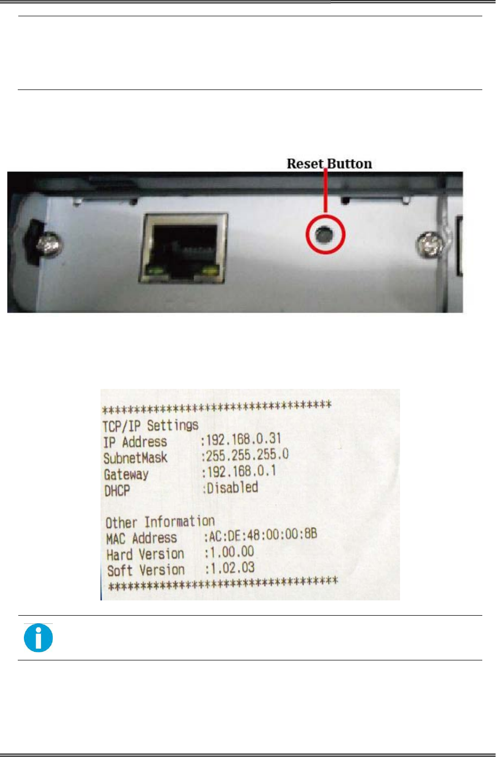
1. Switch on printer, press and hold the Reset key for more than 3 seconds with the tip of pen or
small tool. Then the printer will print out a status sheet as shown below.
The following are printed on the status sheet.
•TCP/IP settings.
• Other Information.
Make sure your PC IP address and printer IP address are in the same section.
Tally Dascom DT-210/230 User Guide V1.3
28
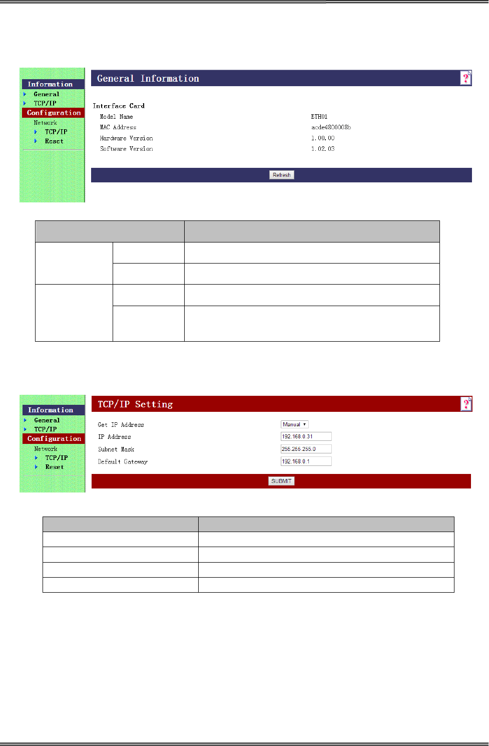
2. The interface is pre-set with the IP address 192.168.0.31. DHCP is disabled. Enter this IP address
in your browser to get access to the built in web page.
Item Explanation
Information General Show the ETH01 information
TCP/IP Show the TCP/IP information
Configuration
Network
TCP/IP Set the TCP/IP information
Reset Reset the ETH01 or return to the factory default
setting
3. Click Configuration→Network→TCP/IP, the default setup for getting IP address is manual, you
can start setting the IP address, subnet mask and default gate way.
Item Explanation
Get IP Address Show the method of setting the IP address
IP Address Show the IP address
Subnet Mask Show the subnet mask of the IP address
Default Gateway Show the default gateway
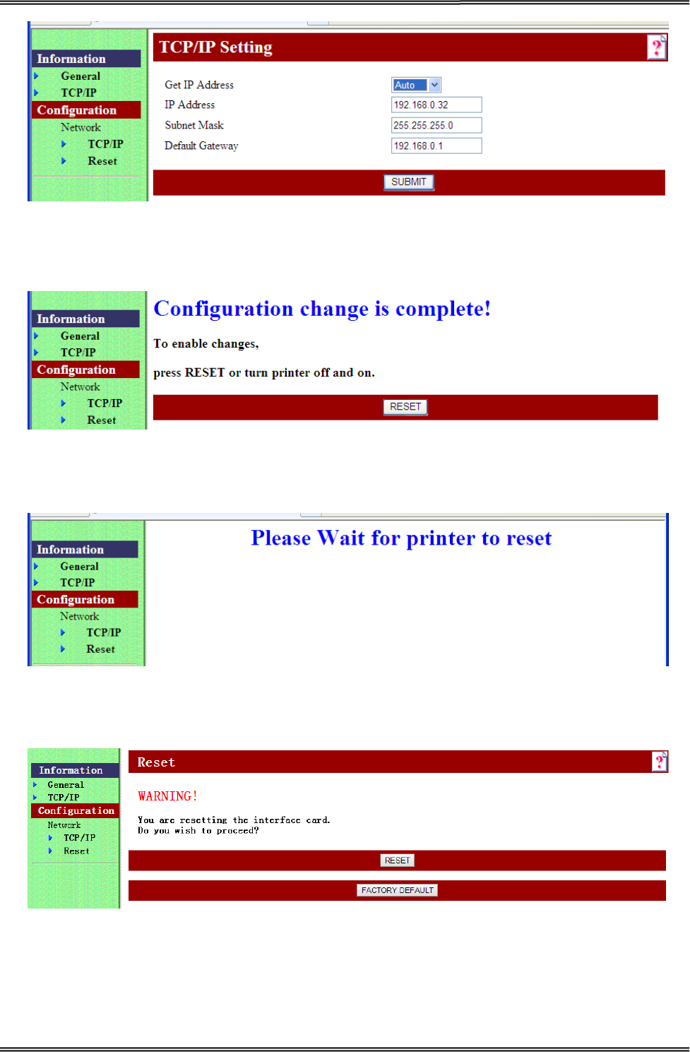
4. If you want to enable DHCP mode, select “Auto” in Get IP address option.
Or you can do this by pressing the reset button next to the RJ45 socket while you switch on your
printer.
Verify the new setting by pressing the button after some seconds again. The new IP address is
being printed.
Tally Dascom DT-210/230 User Guide V1.3
29
5. After TCP/IP setup, click “Submit”, you will see the following interface. Then click “Reset” button,
the parameter will be valid.
6. Configuration page supports initializing TCP/IP parameter. Click Configuration→Network→Reset,
you will see “FACTORY DEFAULT” button. Click the button, Ethernet board TCP/IP parameter will
return to factory default setup. IP Address is 192.168.0.31.
Tally Dascom DT-210/230 User Guide V1.3
30
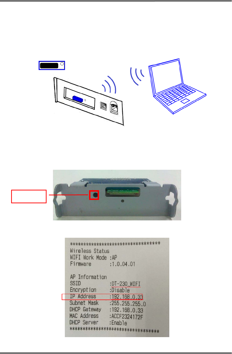
3.6 For Wireless LAN Interface
If your printer connected to the computer with Wireless Ethernet, there are two ways of connection
modes: AP mode and STA mode.
When using the wireless LAN interface, the network configuration is required. Make the settings on
setup page.
If your printer connected to the computer with Wireless Ethernet, there are two ways of connection
modes: AP mode and STA mode.
1. Switch on printer, press Reset key with the tip of pen or a small tool. Printer will print out a Wi-Fi
parameter as shown below.
Reset Button
Tally Dascom DT-210/230 User Guide V1.3
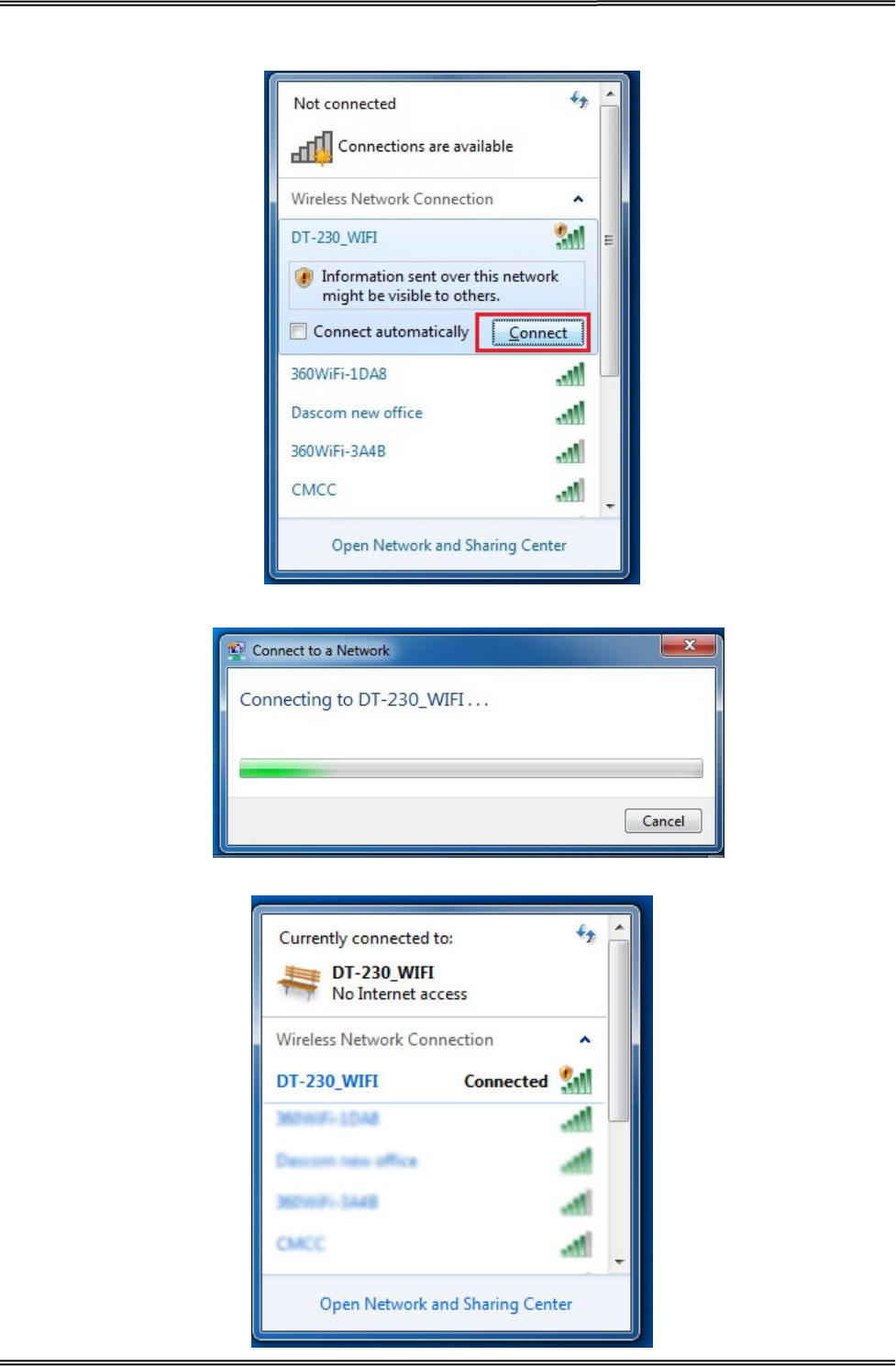
31
2. You will see “DT-230_WIFI” in the wireless network connection list. Click “Connect”.
3. Double click “DT-230_WIFI” for connection. It will display “Connected” if connection is successful.
Tally Dascom DT-210/230 User Guide V1.3
32
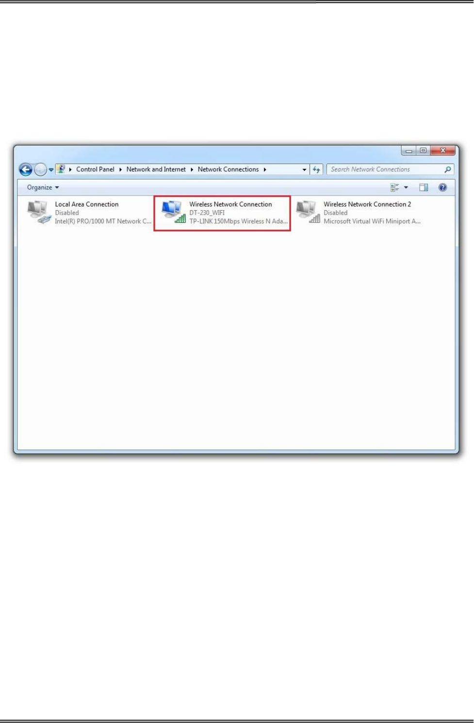
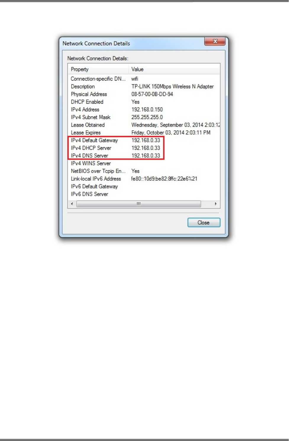
3.6.1 Get IP Address
There are two methods to get the IP address of the printer. One way is to look at the Wi-Fi
parameter sheet. The other way is to look into the Wi-Fi connection details after your printer is
connect to the computer via Wi-Fi module. Here is the procedure:
1. Open the control panel Network and Internet Network Connections.
Then you can see this page: double click “Wireless Network Connection”.
Tally Dascom DT-210/230 User Guide V1.3
33
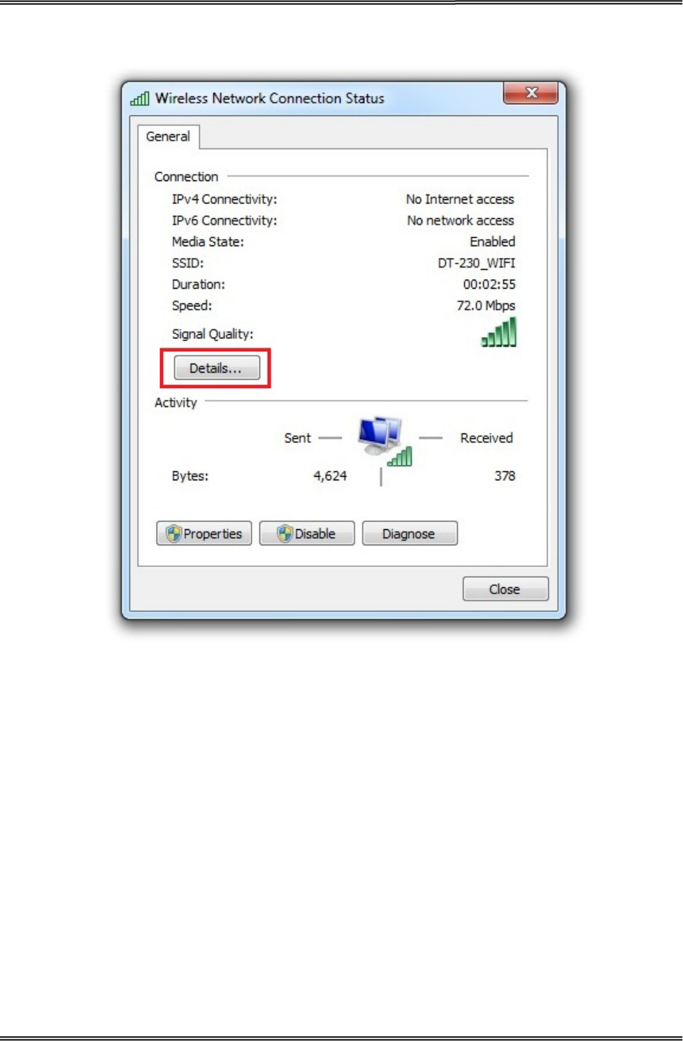
2. Click “Details” button on this page.
Tally Dascom DT-210/230 User Guide V1.3
34
3. Then you can see the IP Address on the Property “IPv4 Default Gateway”: 192.168.0.33
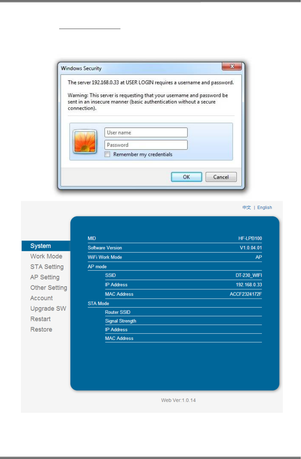
There are two kinds of working mode for Wlan board connection to the PC. One is AP mode, the
other one is STA mode. AP means Access Point (AdHoc Mode); STA means Station mode (Infra
Structure Mode). We would suggest you use AP mode for your initial usage.
Tally Dascom DT-210/230 User Guide V1.3
35
3.6.2 Wlan Setup - AP mode
1. Visit IP Address http://192.168.0.33. Default username is “admin” with password “admin” for
the first time to log in. You will see the following Wi-Fi setup page. Click “Submit” button after
modifying the parameter. Restart printer, new parameter will be valid.
admin
admin
Tally Dascom DT-210/230 User Guide V1.3
36
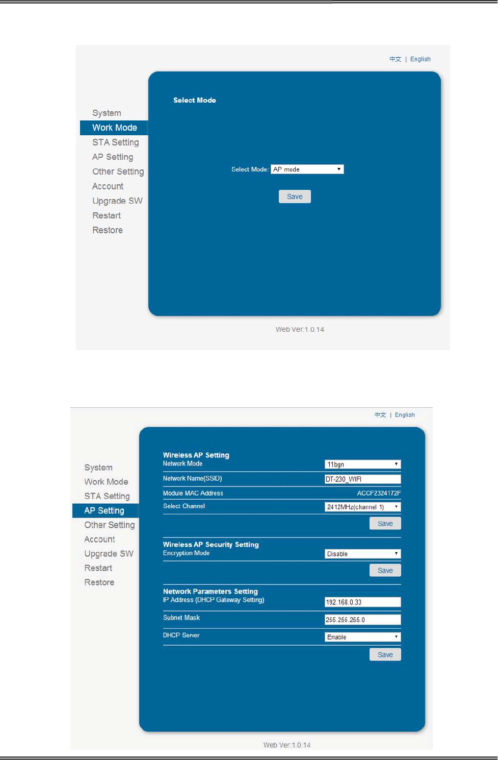
2. Log into work mode option, then choose AP mode. Click “Save” button after modifying the
parameter. Restart printer, new parameter will be valid.
3. Log onto AP setting, Click “Save” button after modifying the parameter such as channel,
encryption mode, and IP address. Restart printer, new parameter will be valid.
Tally Dascom DT-210/230 User Guide V1.3
37
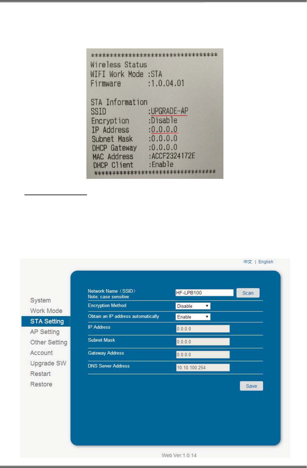
3.6.3 Wlan Setup - STA mode
In the Wi-Fi parameter, if there is IP Address, it suggests they are connected successfully by STA
mode. Otherwise, they are not connected. Like showed in the picture below, they are connected
successfully.
1. Visit http://192.168.0.33
2. Log into work mode option, then choose STA mode. Click “Save” button after modifying the
parameter. Restart printer, new parameter will be valid.
. Default username is admin with password admin for the first time to
log in. You will see the following Wi-Fi setup page. Click “Submit” button after modifying the
parameter. Restart printer, new parameter will be valid.
3. Log onto STA setting, Click “Save” button after modifying the parameter such as SSID, and
encryption mode. Restart printer, new parameter will be valid.
Tally Dascom DT-210/230 User Guide V1.3
38
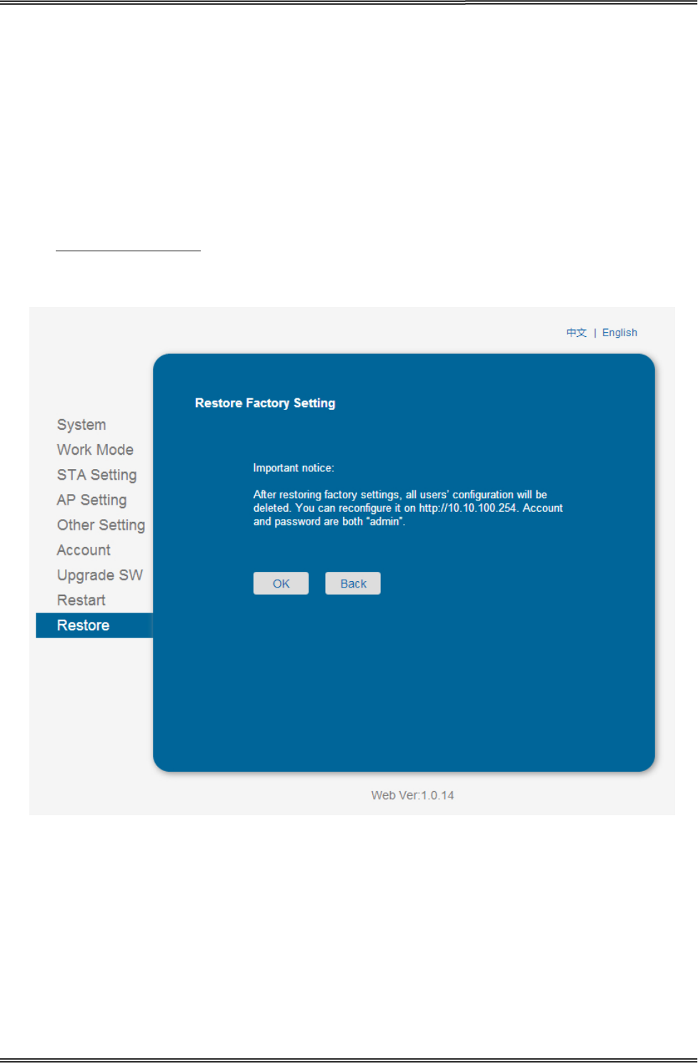
3.6.4 Return to Factory Setting
There are two methods to restore factory setting.
Method One:
1. Turn off the printer.
2. Press and hold the black button on the Wlan board. And then turn on the printer.
3. Wait for five seconds, the Wlan board will return to factory setting.
Method Two:
Visit http://192.168.0.33
. Default username is admin with password admin for the first time to
log in. Click OK on the Restore Page.
Tally Dascom DT-210/230 User Guide V1.3
39
3.7 Connecting to Bluetooth
Communication cable is not required while using Bluetooth
printer. Users have to prepare a
Bluetooth adapter by themselves
and install the adapter in the computer so as to connecting the
Bluetooth device.
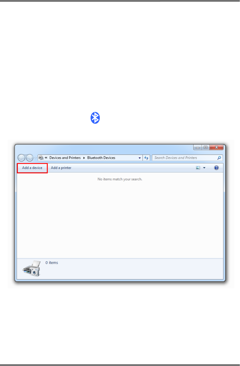
3.7.1 Installing Bluetooth Adapter Driver
1. Install Bluetooth adapter (V2.0 or above version) that prepared by yourself in the PC via USB
interface.
2. Power on printer and load paper roll.
3. Double click the Bluetooth icon at lower right corner on the PC screen. You will see the
following window then Click “Add a device”.
Tally Dascom DT-210/230 User Guide V1.3
40
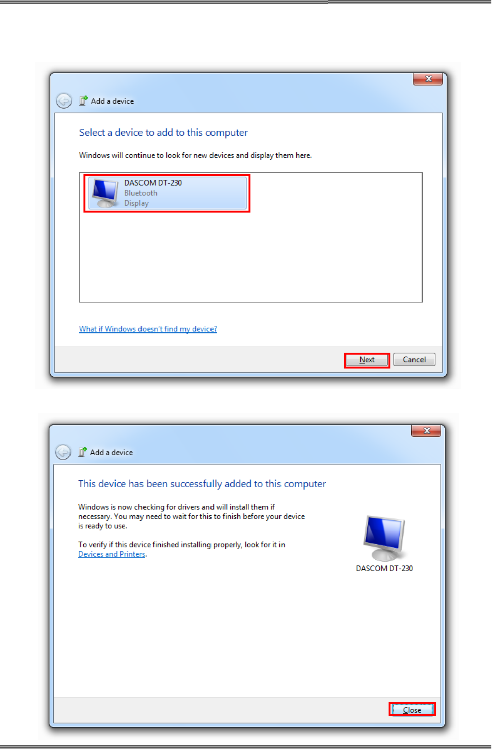
4. Select “Device is ready for searching”, and then click “DASCOM DT-230” for searching the
Bluetooth printer.
5. Then the Bluetooth adapter has been installed in the computer.
Tally Dascom DT-210/230 User Guide V1.3
41
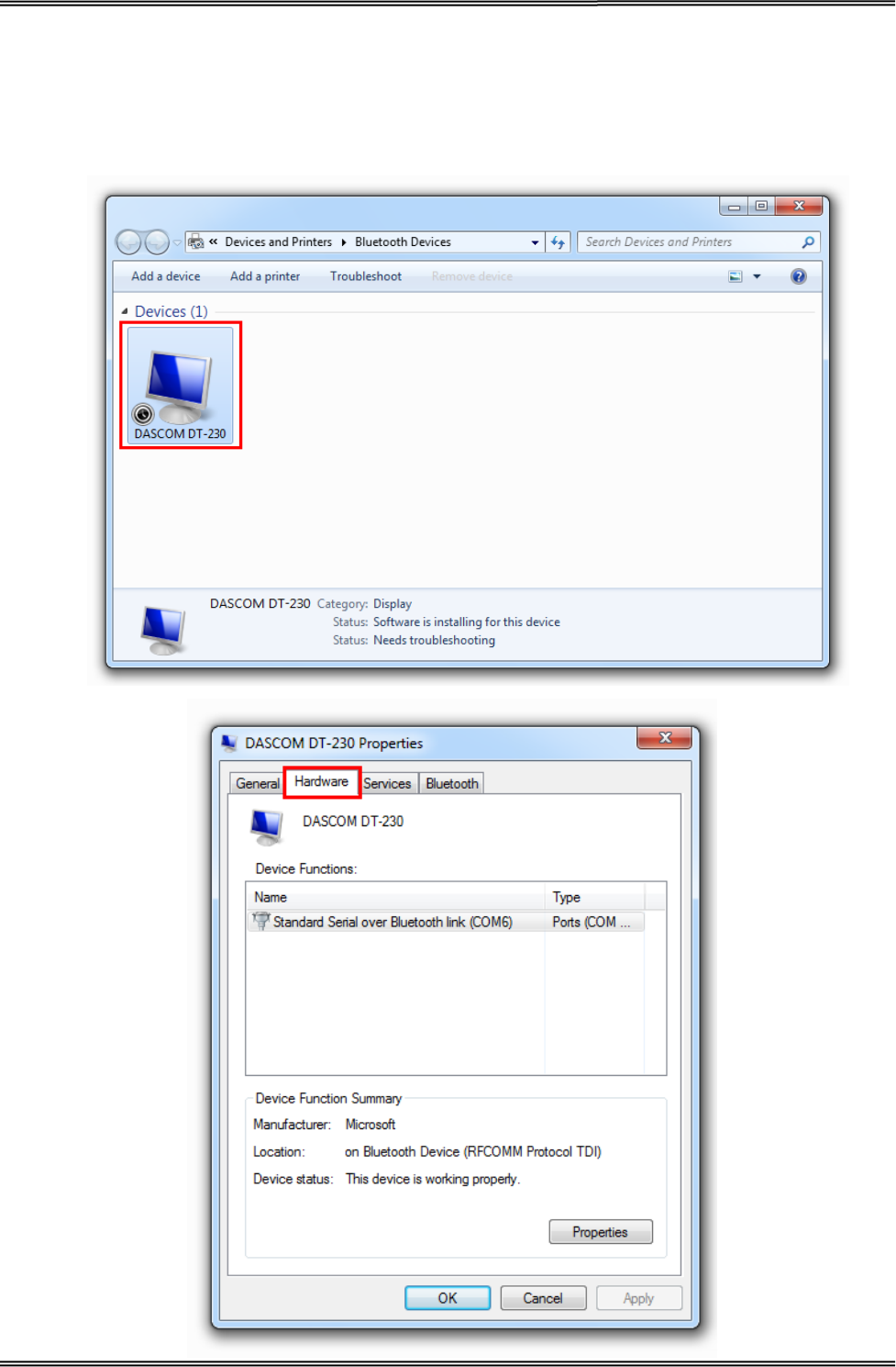
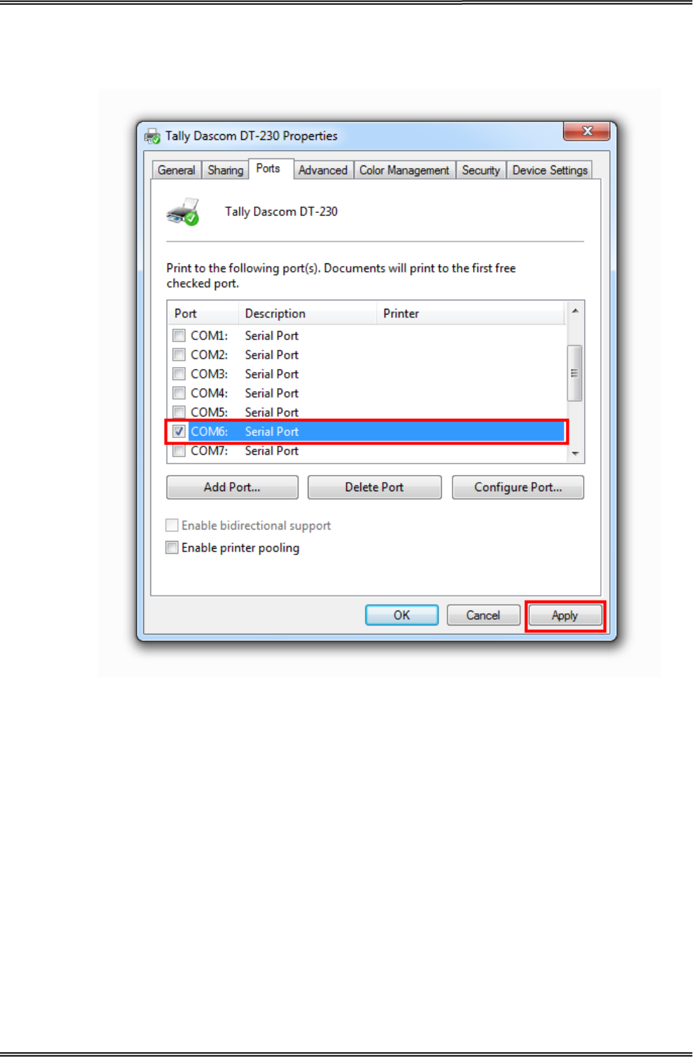
3.7.2 Changing Printer Port
1. Right click any printer, select Properties → Interface, and select the output port that you have
put down then click “Apply”.
Tally Dascom DT-210/230 User Guide V1.3
42
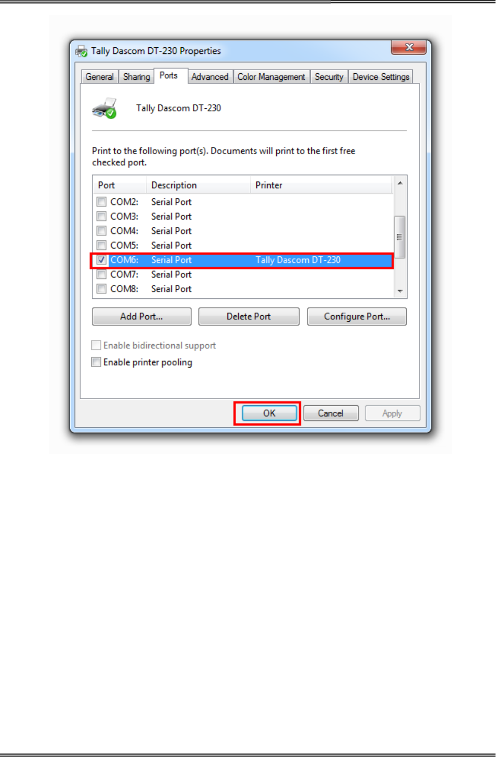
2. Right click any printer, select Properties → Interface, and select the output port that you have
put down (in the case COM6) then click “Apply”.
Tally Dascom DT-210/230 User Guide V1.3
43
Tally Dascom DT-210/230 User Guide V1.3
44
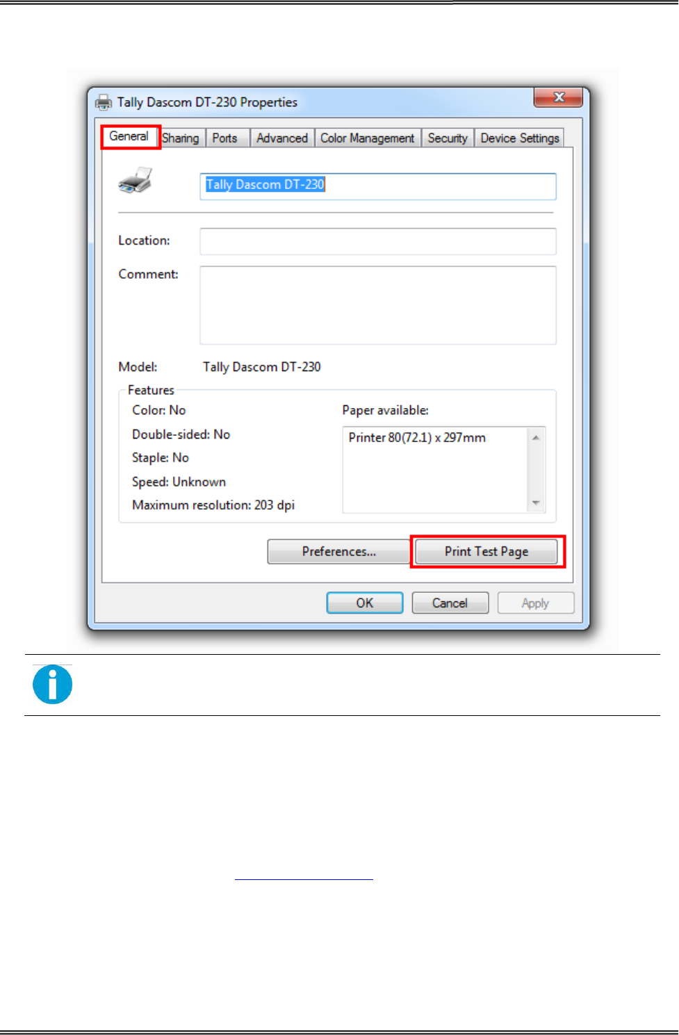
3. Select Normal → Interface, run test page to see the printing outcome.
Setting pages vary depending on the different types of Bluetooth adapter.
3.7.3 Changing Baud Rate of the Printer
The baud rate of the printer and that of the Bluetooth board should be of the same frequency. The
default baud rate of the Bluetooth I/F is 115200 bps, so you have to change the DIP setting so as to
change the printer baud rate. (see Setting DIP Switches on page 48)

Tally Dascom DT-210/230 User Guide V1.3
45
4 SETTING/CHECKING MODES
Besides the ordinary print mode, the printer has the following modes to set or to check settings of
the printer.
• Self-test Mode
• Hexadecimal Dumping Mode
4.1 Self-test Mode
Before you connect the printer to the computer, make sure that the printer is in proper working
order. You can do this by printing a configuration status label.
Follow the steps below to run this mode.
1. Make sure the media is properly loaded, the top cover of the printer is closed and
the printer is power off.
2. While pressing the FEED button, turn on the printer. (Keep pressing the FEED
button until the printer starts printing.)
The printer then starts printing current status of the printer.
With the LAN interface, before printing starts, it takes 6 seconds if the IP address is
fixed and 13 seconds id the IP address is obtained with the automatic setting. (It
may take longer depending on the response time from the host.)
When the printer finishes printing the printer status, the following message is printed and the Paper
LED flashed. (The printer is now in the self-test wait mode.):
“If you want to continue SELF-TEST
Printing, please press FEED button!”
Tally Dascom DT-210/230 User Guide V1.3
46
Here is the self test status page and its explanation. The printout is an example. It may differ
depending of installed options or interfaces:
3. Press the FEED button while the printer is in the self-test mode.
Then the printer will print a rolling pattern using only the built-in character set.
After printing the following message, the printer is initialized and returned to the normal mode.
Model
Firmware Version
S/N
Interface
Number of data bits
Number of stop bits
Flow Control
Parity Checking
Receive error method
Buffer size
Resident Character Types
Density level
DIP Switch setting
SELF-TEST
Model DT-230
Firmware Version : SV1.02.16
S/N: 000000000000
Serial Interface
Baud Rate : 19200 bps
Data bits : 8 bits
Stop bits : 1 bit
Flow Control : DTR/DSR
Parity Checking : None
Receive error : print ‘?’
Buffer Capacity
48K bytes
Resident Character
Alphanumeric
Simple Chinese
Print Density
LIGHT [ 1 2 3 4 ] DARK
Print Speed : 260mm/s
Paper Width : 80mm
BM sensor : Disable
DIP Switch1
1 2 3 4 5 6 7 8
On
Off * * * * * * * *
DIP Switch1
1 2 3 4 5 6 7 8
On
Off * * * * * * * *
If y ou want to continue SELF-TEST
Printing, please press FEED button!

Tally Dascom DT-210/230 User Guide V1.3
47
4.2 Hexadecimal Dumping Mode
This function is to print out all received data in hexadecimal numbers. If printing cannot occur
correctly, this function allows checking whether or not the printer is receiving data correctly.
Follow the steps below to run this mode.
1. Open the roll paper cover.
2. While pressing the FEED button, turn on the printer.
3. Close the roll paper cover.
The printer starts printing “HEX DUMP PRINT MODE” followed by the received data printed in
hexadecimal numbers and some characters.
CAUTION!
• The printer prints “.” if there is no characters corresponding to data.
• During hexadecimal dump, functions except some command will be disabled.
• If print data does not cover a line, press the FEED switch to print the line.
Printing example:
Hexadecimal Dump
To terminate hexadecimal dump,
press FEED button three times.
1B 21 00 1B 26 02 40 40 1B 69 . ! . . & . @@ . i
1B 25 01 1B 63 34 00 1B 30 31 . % . . c 4 . . 0 1
41 42 43 44 45 46 47 48 49 4A A B C D E F G H I J
*** completed ***
Turn off the printer or press the FEED button three times to return to the normal mode.
Tally Dascom DT-210/230 User Guide V1.3
48
5 SETTING DIP SWITCHES
On this printer, you can make various settings such as printer density, baud rate, and auto-cutter
enable/disable etc. with DIP switches.
The DIP switches are already set for the current interfaces. Change the setting if necessary.
Functions of the DIP switches differ depending on the interface.
5.1 Setting Procedure
Follow the steps below to change the DIP switch settings.
CAUTION!
• Before you remove the DIP switch cover, turn the printer off. Otherwise,
short-circuit may cause the printer to malfunction.
• DIP switch settings are enabled only when the power is turned on or the
printer is reset via the interface. If the settings are changed after that, the
functions will not change.
1. Make sure the power supply for the printer is turned off.
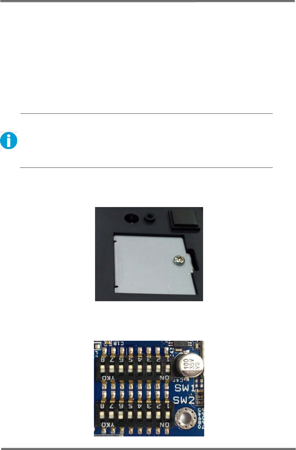
2. Unscrew the screw to remove the DIP switch cover from the base of the printer.
Metal Plate
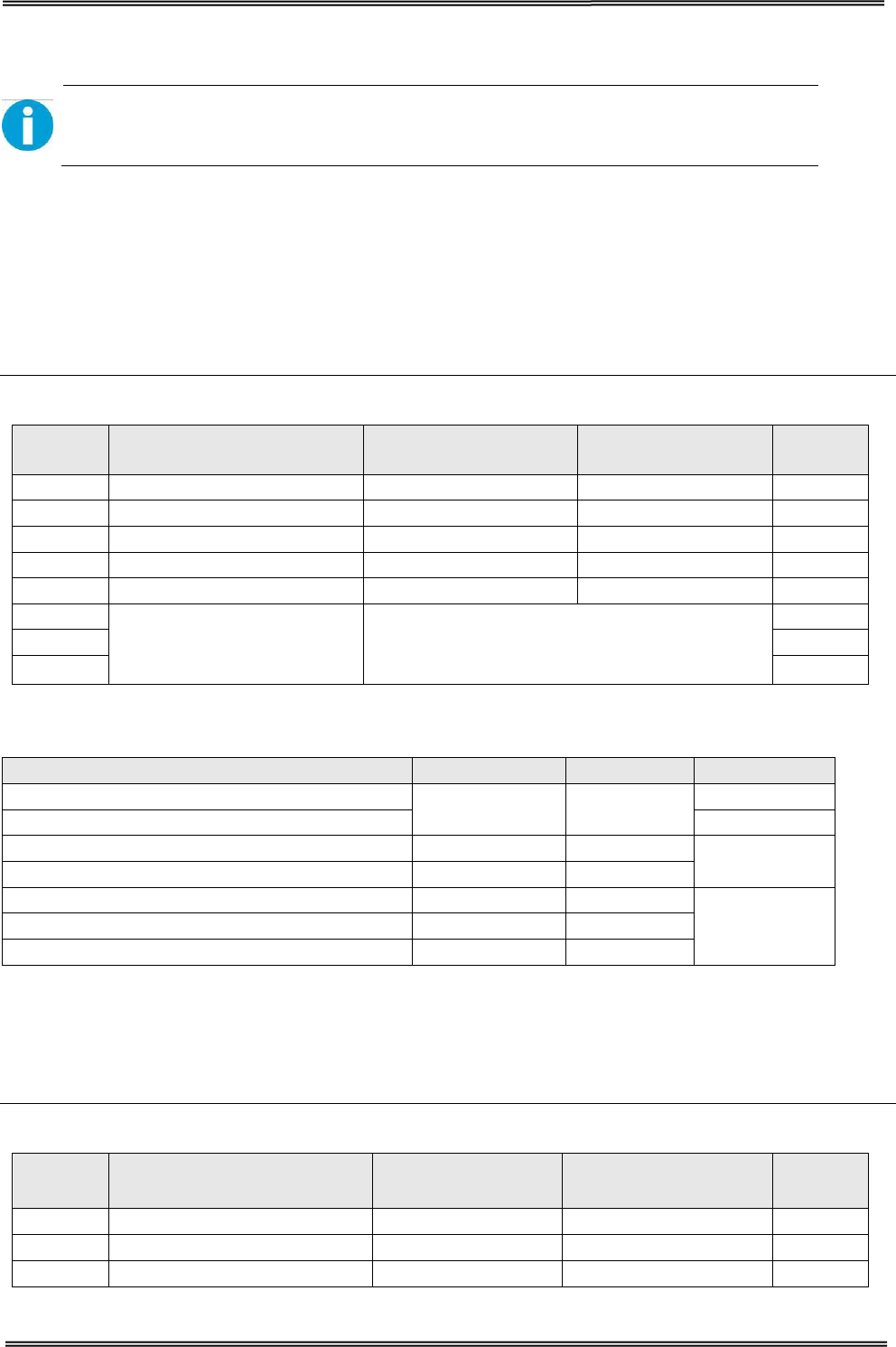
3. Set the DIP switches, using the tip of a tool, such as a small screwdriver. There are
two DIP switch banks on the main controller board (SW1 and SW2), eight DIP
switches for each bank.
DIP Switch 1 & Switch 2
Tally Dascom DT-210/230 User Guide V1.3
49
4. Replace the DIP switch cover, and screw it in place.
New DIP switch settings are enabled after the printer is turned on!
5.2 For Serial Interface (RS-232C)
When using the built-in USB interface, it is not necessary to change the DIP switch setting but their
function changes. For the details, see “For Parallel and USB2.0 Interface” .
DIP Switches Bank 1
SW Function ON OFF
Initial
setting
1-1
Auto Line Feed at CR
Enable
Disable
OFF
1-2
Handshaking
XON/XOFF
DTR/DSR
OFF
1-3
Data Length
7bits
8bits
OFF
1-4
Parity Check
Yes
No
OFF
1-5
Parity Selection
EVEN
ODD
OFF
1-6
Baud Rate Selection
(bps) See the “Transmission Speed” table below
OFF
1-7
ON
1-8
OFF
Transmission Speed
Transmission Speed (bps: bits per second)
1-6
1-7
1-8
2400
ON OFF
OFF
4800
ON
9600
OFF
ON
OFF
19200 (default) OFF OFF
38400
OFF
ON
ON
57600
OFF
OFF
115200 ON ON
Note: Depending on print conditions, such as print duty, print head temperature, and data
transmission speed, print speed is automatically adjusted, which can cause white lines due to
intermittent print (the motor sometimes stops). To avoid this, set the transmission speed higher or
keep the print speed constant by setting it lower.
DIP Switches Bank 2
SW Function ON OFF Initial
setting
2-1 Reserved - - OFF
2-2
Internal bell control
Internal bell disable
Internal bell enable
OFF
2-3
Auto Cutter
Disable
Enable
OFF
Tally Dascom DT-210/230 User Guide V1.3
50
2-4 BUSY Condition Receive Buffer Full Offline or Receive
Buffer Full OFF
2-5
Print Density See “Selecting the Print Density” on page 48.
OFF
2-6 OFF
2-7
OFF
2-8
Near-End Sensor Status
Disable
Enable
OFF
5.3 For Parallel and USB2.0 Interface
When using the serial interface, it is not necessary to change the DIP switch setting but their function
changes. For the details, see “For Serial Interface (RS-232C)” on page 47 .
DIP Switches Bank 1
SW Function ON OFF Initial
setting
1-1
Auto Line Feed at CR
Enable
Disable
OFF
1-2
~
1-8
Reserved
-
- OFF
DIP Switches Bank 2
SW Function ON OFF Initial
Setting
2-1 Reserved - - OFF
2-2 Internal bell control Internal bell disable Internal bell enable OFF
2-3
Auto Cutter
Disable
Enable
OFF
2-4 BUSY Condition Receive Buffer Full Offline or
Receive
Buffer Enable OFF
2-5
Print Density See “Selecting the Print Density” on page 53.
OFF
2-6
OFF
2-7
OFF
2-8
Near-End Sensor Status
Disable
Enable
OFF
Tally Dascom DT-210/230 User Guide V1.3
51
5.4 Selecting the Print Density
2-5 2-6 2-7 Print Density (Mono color) Default
ON
ON
Reserved
1 (Light)
2
OFF
OFF
Reserved
2 (Standard)
ON
OFF
Reserved
3 (Darker than standard)
OFF
ON
Reserved
4 (Dark)
• If the print density is set to 3 or 4 level, printing speed may be reduced.
• The print density can be set with DIP switches or the customized value.
5.5 Auto Cutter Enable/Disable Selection
Dip Switch Set 2
SW 2-3
ON
Auto Cutter Disabled
OFF
Auto Cutter Enabled
Application
Ignores Auto Cutter error for continuous printing.
Tally Dascom DT-210/230 User Guide V1.3
52
6 TROUBLESHOOTING
Your printer is extremely reliable, but occasionally problems may occur. This chapter provides
information on some of the common problems you may encounter and how you may solve them. If
you encounter problems that you cannot resolve, contact your dealer for assistance.
Read the following instructions before maintenance and avoid incorrect operation, so as to prevent
injury to you and damage to the printer.
6.1 Error Status
LED indicators on the control panel and buzzer alarm
Trouble occur during printing
Trouble Potential Problem Solution
Colored stripe in the paper Paper near end Install a new roll of paper.
Blurred or spot printing
Incorrect roll paper
Install the paper roll correctly.
Poor paper quality
Use recommended thermal roll paper.
Dirty thermal head or print
roller Clean the thermal head or print roller.
Low Print density Increase the print density level.
Paper Jam Paper stuck Open the printer cover, check the paper
path and remove jammed paper.
Trouble Potential Problem Solution
No LEDs on
Incorrect power supply cable
connections and power
outlet
Check the power supply cable connections
and the power outlet and correct them.
PCB damaged Contact your dealer for assistance.
Paper LED always on Paper near end The roll paper is near end, the printer can
work normally, procure new paper.
Error LED always on and
beeper alarms Printer Cover open Close the Printer Cover.
Power, Paper and Error
LEDs always on and
beeper alarms
Paper end Reload the roll paper.
Error LED blinks and
beeper alarms
Thermal Print Head
overheated
Turn the printer off and wait some minutes
before you resume.
Overvoltage
Print with specified voltage.
Low-voltage Print with specified voltage, use original
power adapter.
Tally Dascom DT-210/230 User Guide V1.3
53
Vertical dot line missing
Dirty thermal head or print
Clean the thermal head or print roller.
Thermal head damaged
Contact your dealer for assistance.
6.2 Removing Jammed Paper
When a paper jam occurs, never pull out the paper forcibly. Open the roll paper cover and remove
the jammed paper.
When the cover cannot be opened, follow the steps below to remove the jammed paper.
Printhead may be hot, please do not touch!
1. Turn off the printer.
2. Lift up the cutter cover to open it like the picture shows.
3. Turn the knob until the cutter blade returns to the normal position.
This returns the cutter blade to the normal position. There is label near the cutter to assist you.
Tally Dascom DT-210/230 User Guide V1.3
54
4. Close the cutter cover.
5. Open the printer cover and remove the jammed paper.
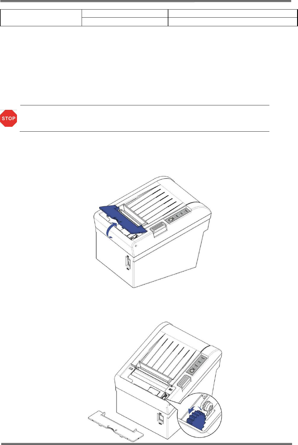
6.3 Cleaning Thermal Head
DASCOM recommends cleaning the thermal print head periodically (generally every 3 months) to
maintain receipt print quality.
• After printing, the thermal print head becomes very hot. Be careful not to
touch it and to let it cool before you clean it.
•
Do not damage the thermal print head by touching it with your fingers or any
hard object.
Turn off the printer, open the printer cover, and clean the thermal elements of the print head with a
cotton swab moistened with an alcohol solvent (ethanol, methanol, or isopropyl).
Depending on the roll paper used, paper dust may stick to the platen roller and roll paper end sensor.
To remove the paper dust, clean the platen roller and roll paper end sensor with a cotton swab
moistened with water. Turn on the printer power only after the water has completely dried.

Tally Dascom DT-210/230 User Guide V1.3
55
7 SPECIFICATIONS
7.1 Printer Specification
Print
Parameter
Print method Direct thermal line printing
Resolution 203DPI, 8dots/mm
Print speed DT-230: 260mm/s Default; 240-270mm/s adjustable via DIP.
DT-210: 220mm/s Default; 210-230mm/s adjustable via DIP.
Print width 72mm (576dots)
Interface
USB (On-board) + Cash Drawer (On-board) + one optional
interface (daughter board): Serial, Parallel, Ethernet, Wi-Fi or fiscal
interface.
Print density
The density can be adjusted to different levels:
DT-210:
Level 1 Density light: Speed 230 m/s
Level 2 Density middle: Speed 220 m/s
Level 3 Density middle: Speed 210 m/s
Level 4 Density dark: Speed 200 m/s
DT-230:
Level 1 Density light: Speed 270 m/s
Level 2 Density middle: Speed 260 m/s
Level 3 Density middle: Speed 250 m/s
Level 4 Density dark: Speed 240 m/s
Power
consumption 51.6W(Normal)
7W(Standby)
Memory RAM 1Mbytes
Flash 4Mbytes
Receive buffer 48Kbytes
Fonts
Characters
per line
Font A, Special Font A: 48 cpl
Font B, Special Font B: 64 cpl
User-defined Supported
Code page 14
code pages (PC437, PC850, PC852, PC858, PC860, PC863,
PC865, PC866, KU42, TIS11, TIS18, PC720,
PC864
,
WPC1256)
Chinese
Character GB18030 24×24
Barcodes 1D UPC-A, UPC-E, EAN8, EAN13, CODE
39, ITF, CODEBAR, CODE128,
CODE32
2D PDR417, QR code
Graphics
Supports several bitmap densities and download image printing.
(Maximum size of each bitmap is 64kB. The total size of memory is
256K.)
Detect
Function Sensors Paper End, Paper Near End, Paper Jam and Cover Open sensors.
Power Supply
External power adapter
Input AC 100V-240V 50-60Hz
Output DC 24V±5%, 2.15A, A-1009-3P interface
Paper Handling Paper type Standard Thermal Paper (see P31- 5.4 paper specification)

Tally Dascom DT-210/230 User Guide V1.3
56
Paper width 79.5±0.5mm/57.5±0.5mm
Paper
thickness 0.056~0.1mm
Paper roll
diameter
Max. OD ∮83mm
Min. ID ∮13mm
Paper load Upward cover open and Easy paper loading
Paper cut Manual tear; Auto-cutter (hay cutter type) and partial cut.
Emulation ESC/POS (TM-T88IV) Compatible command set
Noise The noise level will be less than 50 dBA at 260mm/s printing speed
(to be measured in accordance with ISO 7779)
Physical Spec.
Operating
condition 5~45℃/10~95%RH
Storage
condition -10~50℃/10~95%RH
Dimensions 147×198×146 (W×L×H mm)
Color Black
Weight Approx. 1.8kg
Optional Kits Splash cover and Hanging plate
Accessory Interface cover
Reliability
Head lifetime 150km
MTBF 360, 000 hours
Cutter
lifetime 2,000,000 cuts
MCBF 52,000,000 lines
Software Driver Windows, 32 & 64 Bit
Certification CCC, CE, UL, FCC, Energy Star
Tally Dascom DT-210/230 User Guide V1.3
57
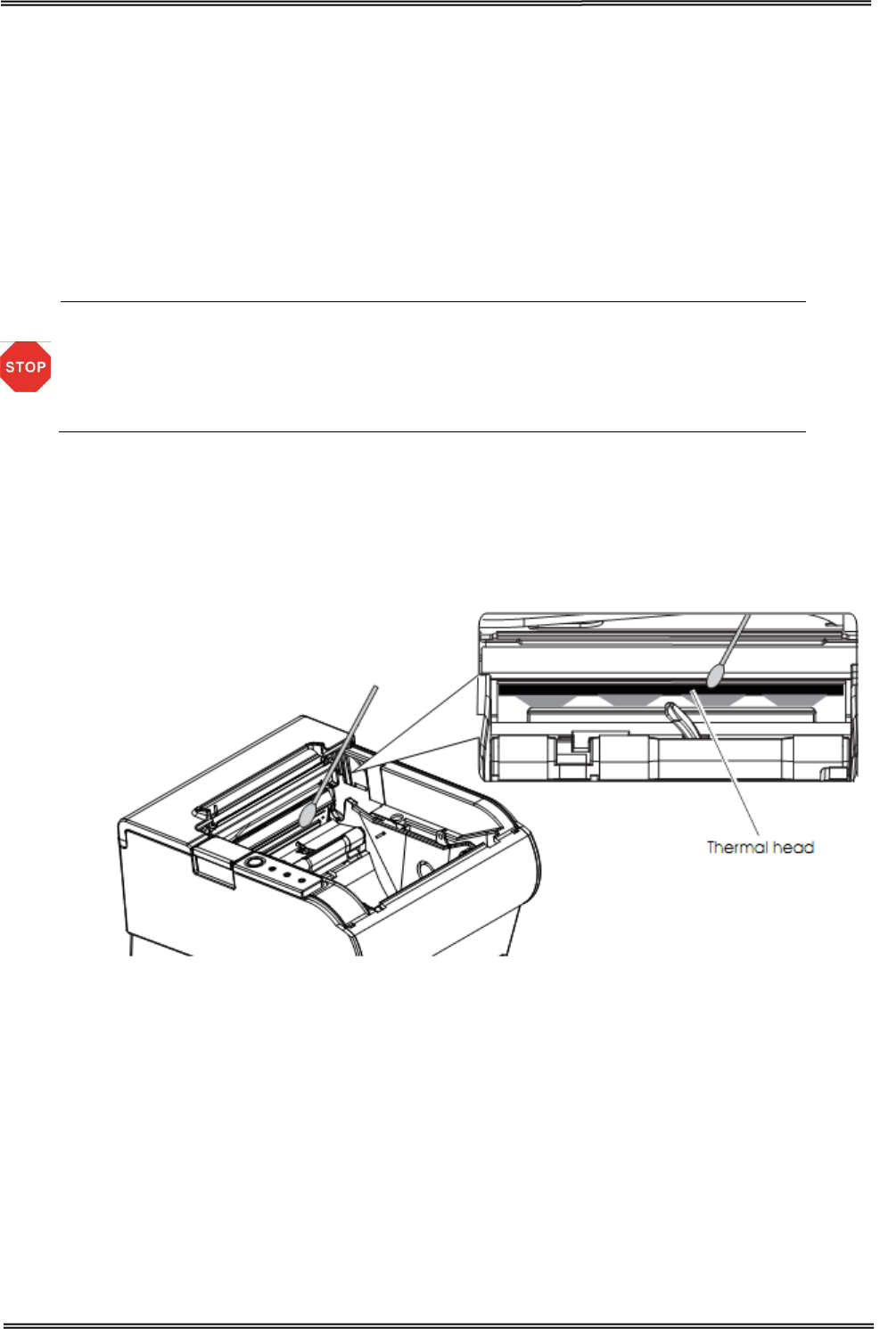
7.2 External Dimension and Mass
• Width: Approximately 147 mm {5.78”}
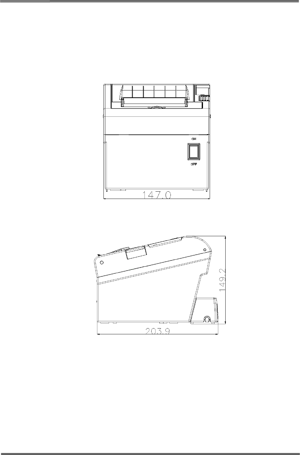
• Depth: Approximately 203.9 mm {8.03”}
• Width: Approximately 149.2 mm {5.87”}
• Mass: DT-210: Approx. 1.6kg {3.53lb} (excluding power adapter)
DT-230: Approx. 1.7kg {3.75lb} (excluding power adapter)
Front View
Side View
Tally Dascom DT-210/230 User Guide V1.3
58
7.3 Interfaces
Power Supply interface, USB interface and cash drawer interface are standard interfaces for the printer.
Serial interface, Parallel interface, Ethernet interface and Wi-Fi interface are optional interfaces for the
printer.
The interface pin assignment is listed below.
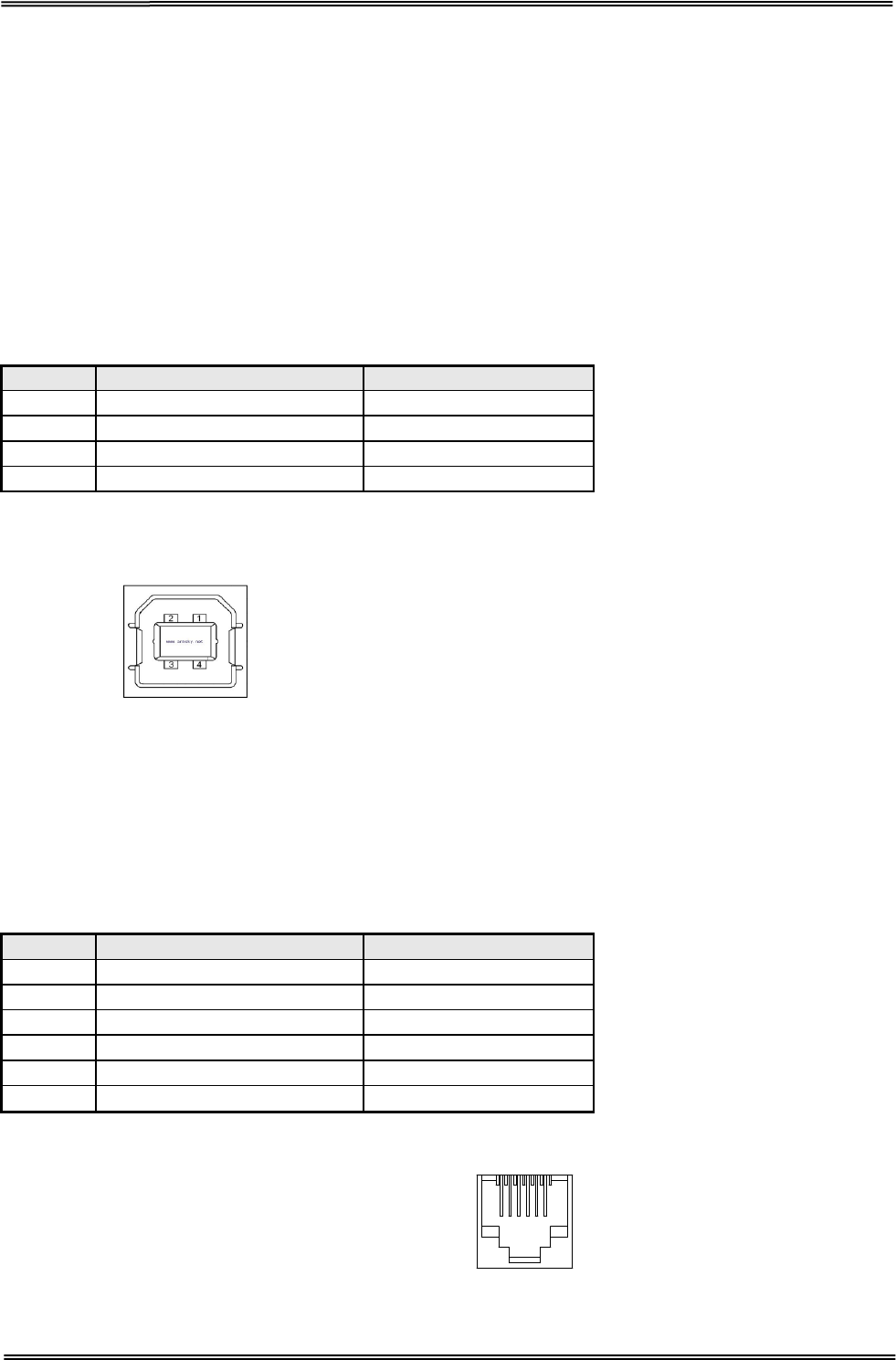
7.3.1 USB interface
USB interface pin assignment
PIN No.
Description
Classic wire color
1
VBUS
Red
2
D-
White
3
D+
Green
4
GND
Black
USB interface connector diagram
7.3.2 Cash Drawer interface
Cash Drawer interface pin assignment
Cash drawer interface supports DC24V, 1A, RJ-11 6P type socket.
Pin. No.
Description
Direction
1
Frame Ground
-
2
Drawer kick-out drive signal 1
Output
3
Drawer open/close signal
Input
4
+24V
-
5
Drawer kick-out drive signal 2
Output
6
GND
-
Cash Drawer interface connector diagram
1 6
Tally Dascom DT-210/230 User Guide V1.3
59
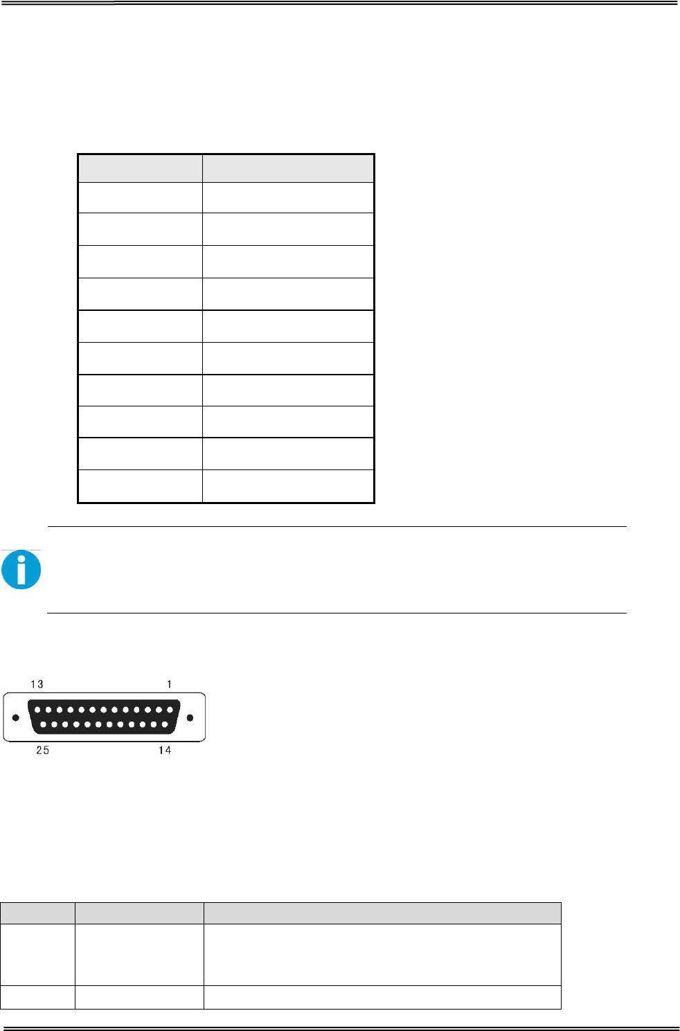
7.3.3 Serial interface
Serial interface pin assignment
Serial interface compatible with RS-232 standard, with 25 pin (D hole type) socket.
PIN No. Description
PIN 1 Frame Ground
PIN 2 TXD
PIN 3 RXD
PIN 4 RTS
PIN 5 Unconnected
PIN 6 DSR
PIN 7 Signal Ground
PIN 8~19 Unconnected
PIN 20 DTR
PIN 21~25 Unconnected
User can view the setting of interface via printing configuration sample.
The default setting of serial interface is
as follow, 38400 bps (baud rates), 8 bit (data
bit), 1 bit (stop bit), no parity, support RTS/CTS handshaking protocol.
Serial interface connector diagram
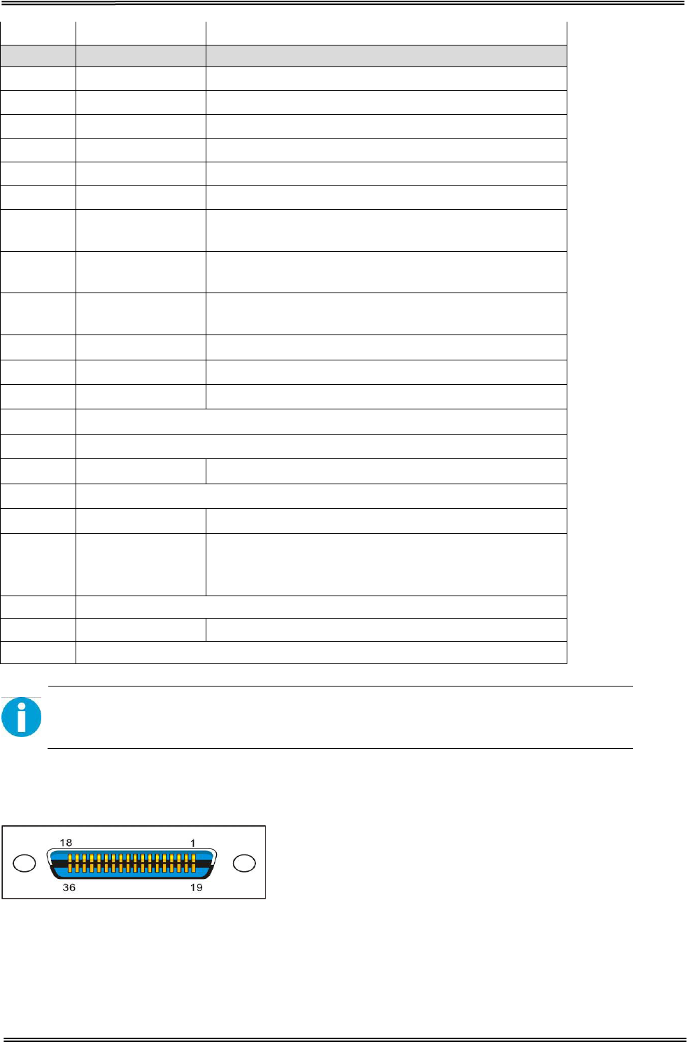
7.3.4 Parallel interface
Parallel interface pin assignment
Parallel interface with 36 pin CENTRONICS socket.
Pin No. Signal From Description
1 H
Strobe Signal; Data latch pulse, latch the data to
the printer at the rising edge of the negative
pulse.
2 H Data 0 (The lowest bit)
Tally Dascom DT-210/230 User Guide V1.3
60
3 H Data 1
Pin No. Signal From Description
4 H Data 2
5 H Data 3
6 H Data 4
7 H Data 5
8 H Data 6
9 H Data 7 (The highest bit)
10 P ACK Signal; Printer response signal, indicates that
the printer has received a Data byte.
11 P Busy Signal; The printer is busy; High level
indicates that the printer can’t receive data.
12 P PE Signal; Paper end signal; High level indicates
that the printer is out of paper.
13 - Unconnected
14 - Unconnected
15 - Unconnected
16 Logic Ground
17 Frame Ground, separated from logic ground.
18 - Unconnected
19~30 Logic Ground
31 - Unconnected
32 P
Printer error signal. Low level indicates that an
error occurs in the printer. It will come with paper
end.
33 Logic Ground
34~35 - Unconnected
36 Unconnected
H indicates that signal comes from Host computer; P indicates that signal comes
from Printer.
Parallel interface connector diagram
Tally Dascom DT-210/230 User Guide V1.3
61
7.3.5 Ethernet interface
Ethernet interface pin assignment
Pin. No. Name Description
1 TX+ Tranceive Data+
2 TX- Tranceive Data-
3 RX+ Receive Data+
4 n/c Not connected
5 n/c Not connected
6 RX- Receive Data-
7
n/c Not connected
8 n/c Not connected
Ethernet interface connector diagram
7.3.6 Wi-Fi interface
Wi-Fi interface supports 2.4 GHz, IEEE Std. 802.11b standard.
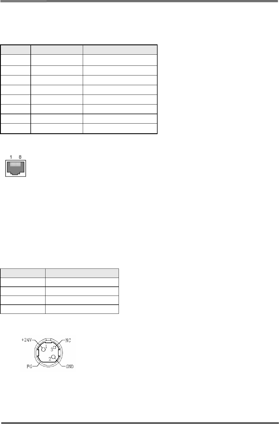
7.4 Power Adapter
Power Socket pin assignment
Pin Number
Signal Name
1 +24 V
2 GND
3 N.C
SHELL F.G.
Power Supply connector diagram
Power Supply interface type
Printer - Unetop DC-002 or similar products
Computer - Unetop DP-002 or similar products
Tally Dascom DT-210/230 User Guide V1.3
62
7.5 Paper Specification
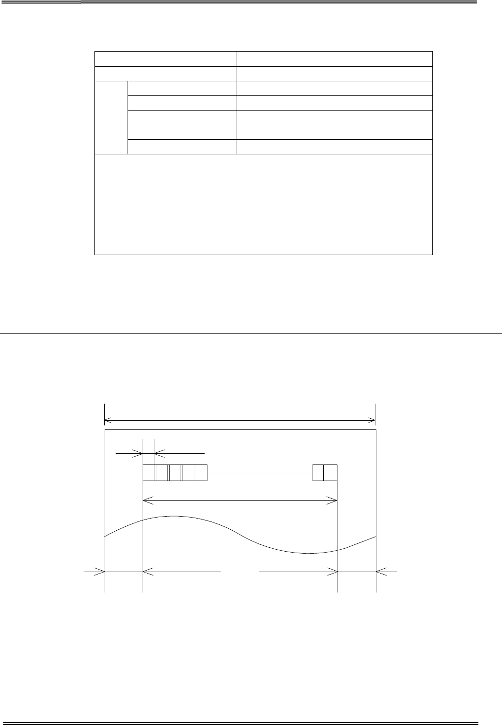
7.5.1 Printable Area
80 mm paper width printing
The printable area of a paper with width of 79.5 ± 0.5 mm {3.13 ± 0.02"} is 72.2 ± 0.2 mm {2.84 ± 0.008"}
(576 dots) and the space on the right and left sides are approximately 3.7 ± 2 mm {0.15 ± 0.079"}.
79.5 ± 0.5 mm {3.13 ± 0.02"}
0.141 ± 0.05 mm {0.056 ± 0.002"}
72.2 ± 0.2 mm {2.84 ± 0.008"}
3.7 mm {0.15} 3.7 mm {0.15}
All the numeric values are typical.
Paper type Specified thermal paper
Form
Roll paper
Size
Roll paper diameter 83 mm {3.27"} maximum
Min. core diameter 13mm
Take-up roll paper
width
80 + 0.5/-1.0 mm
Paper width 79.5 ± 0.5 mm
CAUTION
• Paper must not be pasted to the roll paper spool.
• The remaining amount of the roll paper when a roll
paper near-end is detected differs depending on the spool
type.
Tally Dascom DT-210/230 User Guide V1.3
63
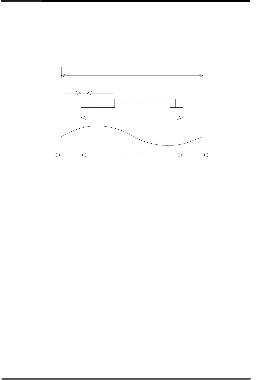
58 mm paper width printing
The printable area of a paper with width of 57.5 ± 0.5 mm {2.26" ± 0.02"} is 50.8 ± 0.2 mm {2.00"
± 0.008"} (360 dots), and the space is approximately 3.7mm {0.15"} on the left side and approximately
3.0 mm {0.12"} on the right side.
57.5 ± 0.5 mm {2.26 ± 0.02"}
0.141 ± 0.05 mm {0.056 ± 0.002"}
50.8 ± 0.2 mm {2.00 ± 0.008"}
3.7 ± 0.2 mm {0.15 ± 0.079"} 3.0 ± 0.2 mm {0.12 ± 0.079"}
All the numeric values are typical.
Tally Dascom DT-210/230 User Guide V1.3
64
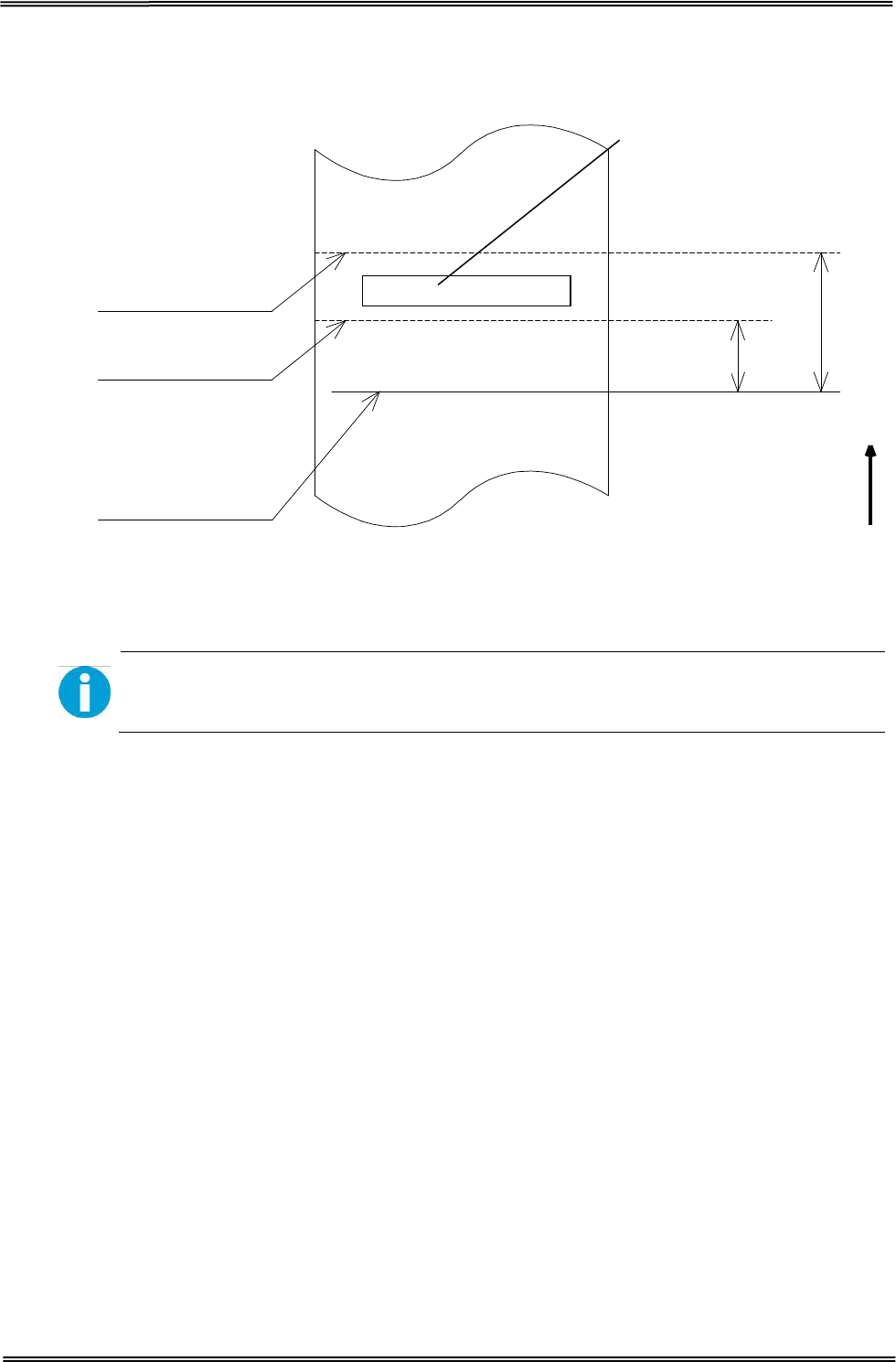
7.5.2 Printing and Cutting Positions
Last line of
a previous receipt
Approx. 29
Manual-cutter position
Auto-cutter blade position Approx. 15
Paper feed direction
Center of the print dotline
[Units: mm (All the numeric values are typical.
The values may vary slightly as a result of paper slack or variations in the
paper. Take this into account when setting the cutting position of the auto
cutter.
Tally Dascom DT-210/230 User Guide V1.3
65
8 CHARACTER CODE PAGES
• The character code tables show only character configurations. They do
not show the actual print pattern.
• “SP” in the table shows a space.
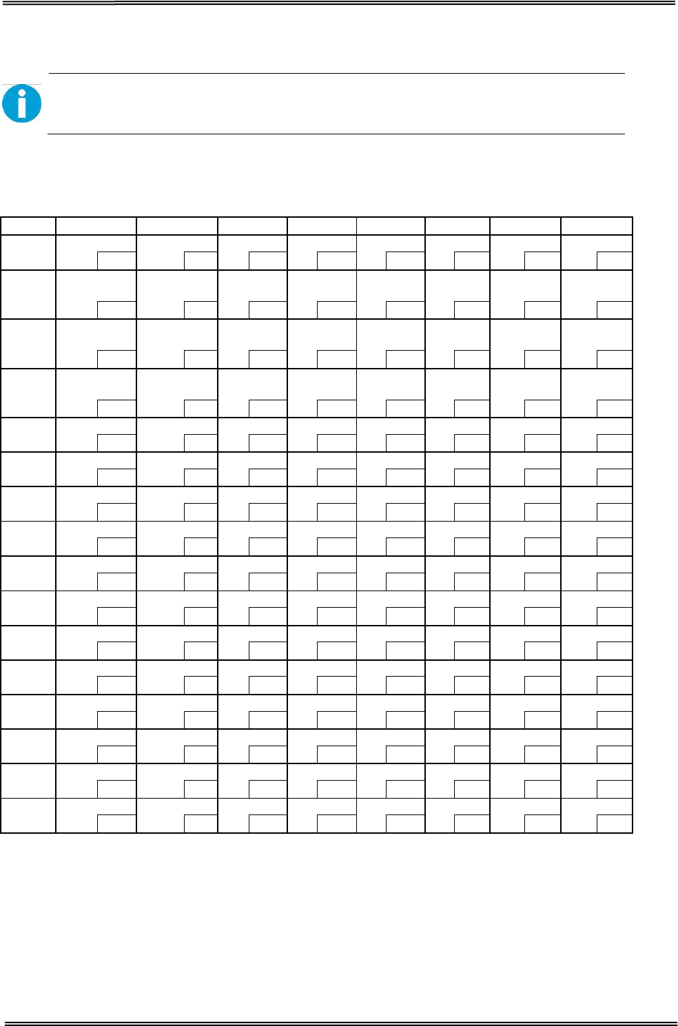
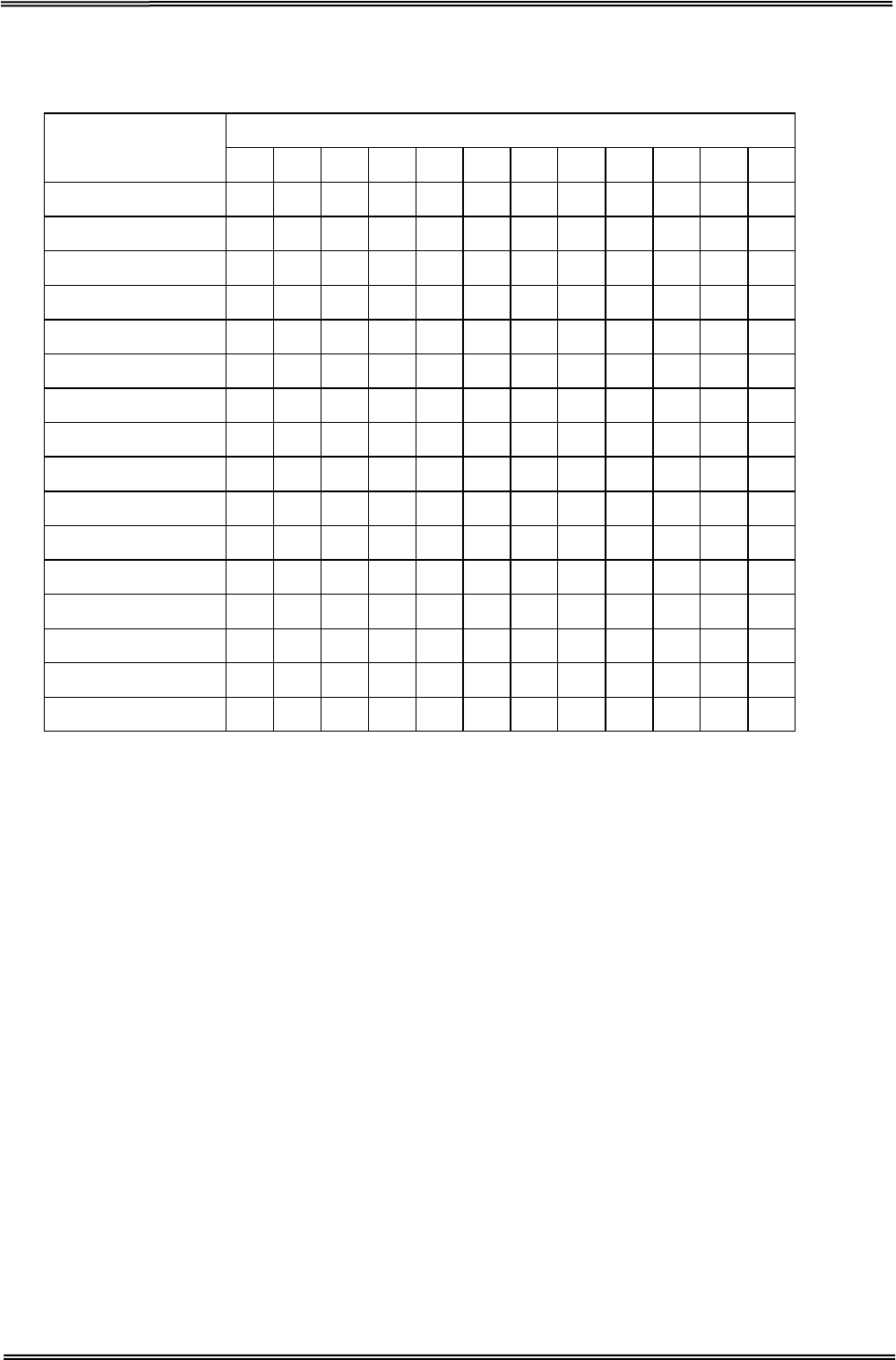
8.1 Common to All Pages (International Character Set: USA)
HEX 0 1 2 3 4 5 6 7
0
NUL
DLE
SP
0
@
P
`
p
00
16 32
48 64
208 224
240
1 XON
!
1
A
Q
a q
01
17
33
49
65
209
225
241
2
“
2
B
R b R
02
18
34
50
66
210
226
242
3 XOFF
#
3
C
S
c s
03 19 35 51 67 211 227 243
4
EOT
DC4
$
4
D
T
d
t
04
20 36
52 68
212 228
244
5 ENQ
NAK
%
5
E
U
e u
05 21 37 53 69 213 229 245
6
ACK
&
6
F
V
f
V
06
22 38
54 198
214 230
246
7
CAN
‘
7
G
W
g
w
07 23 39 55 199 215 231 247
8
(
8
H
X
h
x
08
24 40
56 200
216 232
248
9
HT
)
9
I
Y
i
y
09 25 41 57 201 217 233 249
A
LF
*
:
J
Z
j
Z
10
26 42
58 202
218 234
250
B
ESC
+
;
K
[
k
{
11 27 43 59 203 219 235 251
C
FF
FS
,
<
L
\
l
|
12
28 44
60 204
220 236
252
D CR GS
-
=
M
] m }
13 29 45 61 205 221 237 253
E
RS
.
>
N
^
n
~
14
30 46
62 206
222 238
254
F
/
?
O
_
o
SP
15 31 47 63 207 223 239 255
Tally Dascom DT-210/230 User Guide V1.3
66
8.2 International Character Sets
Country
ASCII code (Hex)
23
24
40
5B
5C
5D
5E
60
7B
7C
7D
7E
USA
#
$
@
[
\
]
^
`
{
|
}
~
France
#
$
à
°
ç
§
^
`
é
ù
è
¨
Germany
#
$
§
Ä
Ö
Ü
^
`
ä
ö
ü
β
U.K.
£
$
@
[
\
]
^
`
{
|
}
~
Denmark I
#
$
@
Æ
Ø
Å
^
`
æ
ø
å
~
Sweden
#
¤
É
Ä
Ö
Å
Ü
é
ä
ö
å
ü
Italy
#
$
@
°
\
é
^
ù
à
ò
è
ì
Spain I
Pt
$
@
¡
Ñ
¿
^
`
¨
ñ
}
~
Japan
#
$
@
[
¥
]
^
`
{
|
}
~
Norway
#
¤
É
Æ
Ø
Å
Ü
é
æ
ø
å
ü
Denmark II
#
$
É
Æ
Ø
Å
Ü
é
æ
ø
å
ü
Spain II
#
$
á
¡
Ñ
¿
é
`
í
ñ
ó
ú
Latin America
#
$
á
¡
Ñ
¿
é
ü
í
ñ
ó
ú
Korea
#
$
@
[
W
]
^
`
{
|
}
~
Slovenia/ Croatia
#
$
Ž
Š
Đ
Ć
Č
ž
š
đ
ć
č
China
#
Ұ
@
[
\
]
^
`
{
|
}
~
Tally Dascom DT-210/230 User Guide V1.3
67
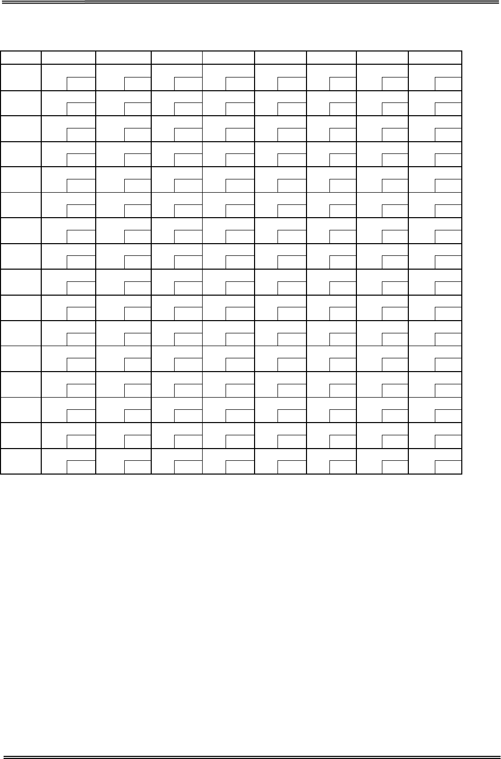
8.3 [User-defined page]
HEX 8 9 A B C D E F
0 SP SP
SP
SP
SP
SP
SP
SP
128
144 160
176 192
208 224
240
1
SP
SP
SP
SP
SP
SP
SP
SP
129 145 161 177 193 209 225 241
2
SP
SP
SP
SP
SP
SP
SP
SP
130
146 162
178 194
210 226
242
3
SP
SP
SP
SP
SP
SP
SP
SP
131 147 163 179 195 211 227 243
4 SP
SP
SP
SP
SP
SP
SP
SP
132
148 164
180 196
212 228
244
5
SP
SP
SP
SP
SP
SP
SP
SP
133 149 165 181 197 213 229 245
6
SP
SP
SP
SP
SP
SP
SP
SP
134
150 166
182 198
214 230
246
7
SP
SP
SP
SP
SP
SP
SP
SP
135 151 167 183 199 215 231 247
8
SP
SP
SP
SP
SP
SP
SP
SP
136
152 168
184 200
216 232
248
9 SP
SP
SP
SP
SP
SP
SP
SP
137
153
169
185
201
217
233
249
A
SP
SP
SP
SP
SP
SP
SP
SP
138
154 170
186 202
218 234
250
B SP
SP
SP
SP
SP
SP
SP
SP
139 155 171 187 203 219 235 251
C
SP
SP
SP
SP
SP
SP
SP
SP
140
156 172
188 204
220 236
252
D
SP
SP
SP
SP
SP
SP
SP
SP
141 157 173 189 205 221 237 253
E
SP
SP
SP
SP
SP
SP
SP
SP
142
158 174
190 206
222 238
254
F
SP
SP
SP
SP
SP
SP
SP
SP
143 159 175 191 207 223 239 255

Tally Dascom DT-210/230 User Guide V1.3
68
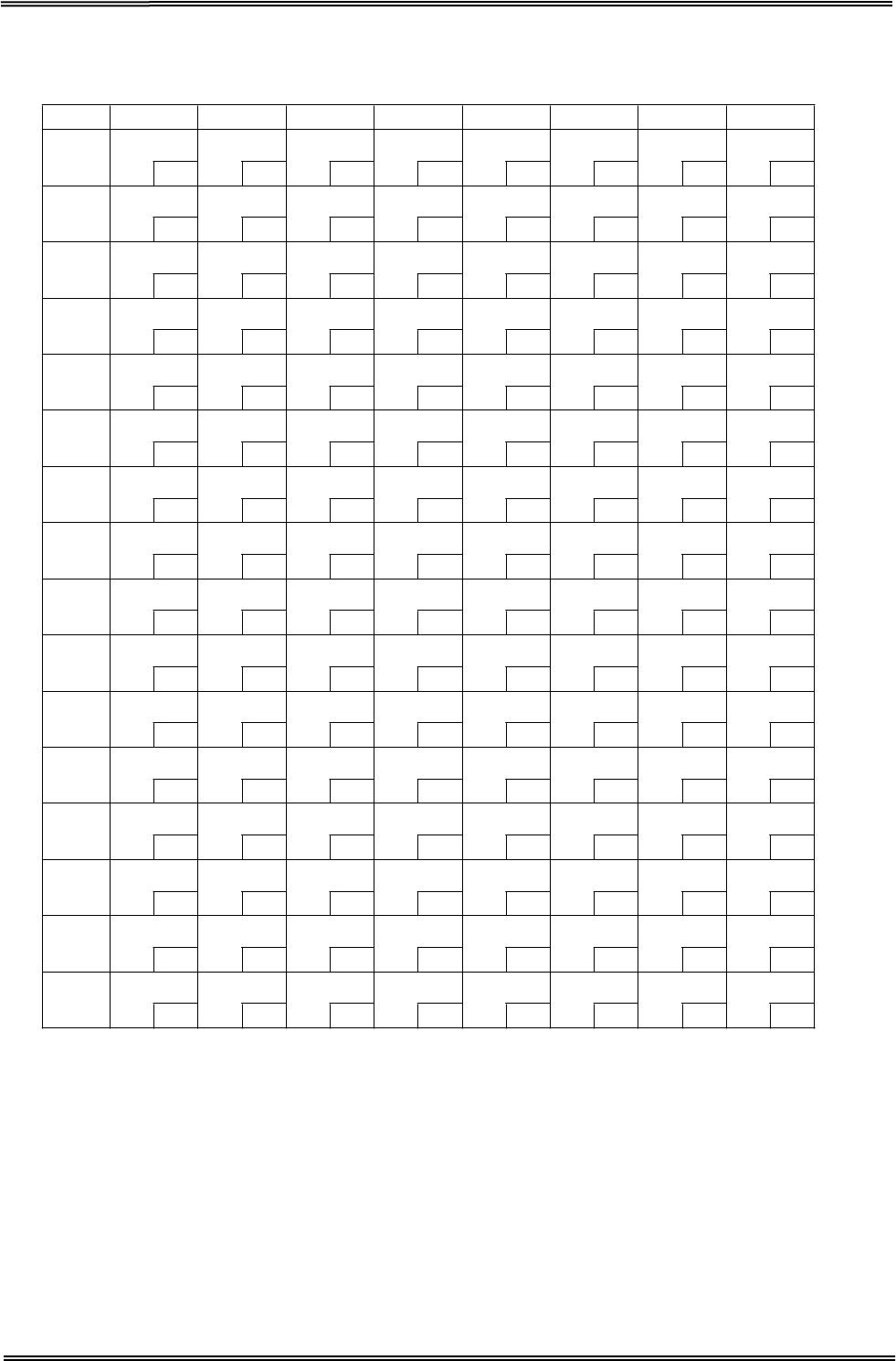
8.4 [PC437: USA, Standard Europe]
HEX 8 9 A B C D E F
0
Ç
É
á
░
└
╨
α
≡
128
144
160
176 192
208 224
240
1 ü æ
í
▒
┴
╤
β
±
129 145
161
177 193 209 225 241
2 é Æ ó ▓ ┬
╥
Γ
≥
130
146
162
178 194
210 226
242
3 â ô ú │ ├
╙
π
≤
131 147
163
179 195 211 227 243
4 ä ö ñ ┤ ─ ╘
Σ
⌠
132
148
164
180 196
212 228
244
5 à ò Ñ ╡ ┼
╒
σ
⌡
133
149
165
181
197
213
229
245
6 å û
a
╢
╞
╓
μ
÷
134
150
166
182 198
214 230
246
7 ç ù
o
╖
╟
╫
τ
≈
135 151
167
183 199 215 231 247
8
ê
ÿ
¿
╕
╚
╪
Ф
°
136
152
168
184 200
216 232
248
9
ë
Ö
┌
╣
╔
┘
Θ
•
137 153
169
185 201 217 233 249
A è Ü ¬ ║ ╩ ┌
Ω
·
138
154
170
186 202
218 234
250
B
ï
¢
½
╗
╦
█
δ
√
139 155
171
187 203 219 235 251
C
î
£
¼
╝
╠
▄
∞
n
140
156
172
188 204
220 236
252
D
ì
¥ ¡ ╜ ═ ▌ Φ
²
141 157
173
189 205 221 237 253
E
Ä
Pt
«
╛
╬
▐
ε
■
142
158
174
190 206
222 238
254
F
Å
ƒ
»
┐
╧
▀
∩
SP
143
159
175
191
207
223
239
255

Tally Dascom DT-210/230 User Guide V1.3
69
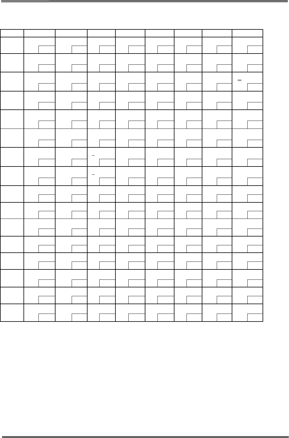
8.5 [PC850: Multilingual]
HEX 8 9 A B C D E F
0
Ç
É
á
░
└
ð
Ó
-
128
144
160
176 192
208 224
240
1 ü æ
í
▒
┴
Ð
β
±
129 145
161
177 193 209 225 241
2 é Æ ó ▓ ┬
Ê
Ô
130
146
162
178 194
210 226
242
3 â ô ú │ ├
Ë
Ò
¾
131
147
163
179
195
211
227
243
4 ä ö ñ ┤ ─
È
õ
¶
132
148
164
180 196
212 228
244
5 à ò Ñ Á ┼
ı
Õ
§
133
149
165
181
197
213
229
245
6 å û
a
Â
ã
Í
μ
÷
134
150
166
182 198
214 230
246
7 ç ù
o
À
Ã
Î
þ
¸
135 151
167
183 199 215 231 247
8
ê
ÿ
¿
©
╚
Ï
Þ
°
136
152
168
184 200
216 232
248
9
ë
Ö
®
╣
╔
┘
Ú
¨
137 153
169
185 201 217 233 249
A è Ü ¬ ║ ╩ ┌ Û
·
138
154
170
186
202
218
234
250
B
ï
ø
½
╗
╦
█
Ù
¹
139 155
171
187 203 219 235 251
C
î
£
¼
╝
╠
▄
ý
³
140
156
172
188 204
220 236
252
D
ì
Ø ¡ ¢ ═ ¦ Ý
²
141 157
173
189 205 221 237 253
E
Ä
×
«
¥
╬
Ì
¯
■
142
158
174
190 206
222 238
254
F Å ƒ » ┐ ¤ ▀
´
SP
143 159
175
191 207 223 239 255
Tally Dascom DT-210/230 User Guide V1.3
70
8.6 [PC852: Latin2]
HEX 8 9 A B C D E F
0 Ç É
128
1 ü Ĺ
129
2 é ĺ
130
3 â ô
131
4 ä ö
132
5 ů ˇ
L
133
6 ć ˇ
l
134
7 ç Ś
135
8 ł ś
136
9 ë Ö
137
A Ő Ü
138
B ő Ť
139
C î ˇ
t
140
D Ź Ł
141
E Ä ×
142
F Ć č
143
á
144
í
145
ó
146
ú
147
Ą
148
ą
149
Ž
150
ž
151
Ę
152
ę
153
SP
154
ź
155
Č
156
ş
157
«
158
»
159
░
160
▒
161
▓
162
│
163
┤
164
Á
165
Â
166
Ě
167
Ş
168
╣
169
║
170
╗
171
╝
172
Ż
173
ż
174
┐
175
└
176
┴
177
┬
178
├
179
─
180
┼
181
Ă
182
ă
183
╚
184
╔
185
╩
186
╦
187
╠
188
═
189
╬
190
¤
191
đ
192
Ð
193
Ď
194
Ë
195
d
ˇ
196
Ň
197
Í
198
Î
199
ě
200
┘
201
┌
202
█
203
▄
204
Ţ
205
Ů
206
▀
207
Ó
208
β
209
Ô
210
Ń
211
ń
212
ň
213
Š
214
š
215
Ŕ
216
Ú
217
ŕ
218
Ű
219
ý
220
Ý
221
ţ
222
´
223
-
224
˝
225
˛
226
ˇ
227
˘
228
§
229
÷
230
¸
231
°
232
¨
233
•
234
ű
235
Ř
236
ř
237
■
238
SP
239
240
241
242
243
244
245
246
247
248
249
250
251
252
253
254
255
Tally Dascom DT-210/230 User Guide V1.3
71
8.7 [PC858: Euro]
HEX 8 9 A B C D E F
0
Ç
É
á
░
└
ð
Ó
-
128
144
160
176 192
208 224
240
1 ü æ
í
▒
┴
Ð
β
±
129 145
161
177 193 209 225 241
2 é Æ ó ▓ ┬
Ê
Ô
130
146
162
178 194
210 226
242
3 â ô ú │ ├
Ë
Ò
¾
131
147
163
179
195
211
227
243
4 ä ö ñ ┤ ─
È
õ
¶
132
148
164
180 196
212 228
244
5 à ò Ñ Á ┼
€
Õ
§
133
149
165
181
197
213
229
245
6 å û
a
Â
ã
Í
μ
÷
134
150
166
182 198
214 230
246
7 ç ù
o
À
Ã
Î
þ
¸
135
151
167
183
199
215
231
247
8
ê
ÿ
¿
©
╚
Ï
Þ
°
136
152
168
184 200
216 232
248
9
ë
Ö
®
╣
╔
┘
Ú
¨
137 153
169
185 201 217 233 249
A è Ü ¬ ║ ╩ ┌ Û
·
138
154
170
186 202
218 234
250
B
ï
ø
½
╗
╦
█
Ù
¹
139 155
171
187 203 219 235 251
C
î
£
¼
╝
╠
▄
ý
³
140
156
172
188 204
220 236
252
D
ì
Ø ¡ ¢ ═ ¦ Ý
²
141 157
173
189 205 221 237 253
E
Ä
×
«
¥
╬
Ì
¯
■
142
158
174
190 206
222 238
254
F Å ƒ » ┐ ¤ ▀
´
SP
143 159
175
191 207 223 239 255

Tally Dascom DT-210/230 User Guide V1.3
72
8.8 [PC860: Portuguese]
HEX 8 9 A B C D E F
0
Ç
É
á
░
└
╨
α
≡
128
144
160
176 192
208 224
240
1 ü À
í
▒
┴
╤
β
±
129 145
161
177 193 209 225 241
2 é È ó ▓ ┬
╥
Γ
≥
130
146
162
178 194
210 226
242
3 â ô ú │ ├
╙
π
≤
131 147
163
179 195 211 227 243
4 ã õ ñ ┤ ─ ╘
Σ
⌠
132
148
164
180 196
212 228
244
5 à ò Ñ ╡ ┼
╒
σ
⌡
133
149
165
181
197
213
229
245
6 Á Ú
a
╢
╞
╓
μ
÷
134
150
166
182 198
214 230
246
7 ç ù
o
╖
╟
╫
τ
≈
135 151
167
183 199 215 231 247
8
ê
Ì
¿
╕
╚
╪
Ф
°
136
152
168
184
200
216
232
248
9
Ê
Õ
Ò
╣
╔
┘
Θ
•
137 153
169
185 201 217 233 249
A è Ü ¬ ║ ╩ ┌
Ω
·
138
154
170
186 202
218 234
250
B
Í
¢
½
╗
╦
█
δ
√
139 155
171
187 203 219 235 251
C
Ô
£
¼
╝
╠
▄
∞
n
140
156
172
188 204
220 236
252
D
ì
Ù ¡ ╜ ═ ▌ Φ
²
141 157
173
189 205 221 237 253
E
Ã
Pt
«
╛
╬
▐
ε
■
142
158
174
190 206
222 238
254
F
Å
Ó
»
┐
╧
▀
∩
SP
143
159
175
191
207
223
239
255
Tally Dascom DT-210/230 User Guide V1.3
73
8.9 [PC863: Canadian-French]
HEX 8 9 A B C D E F
0
Ç
É
¦
░
└
╨
α
≡
128
144
160
176 192
208 224
240
1 ü È
´
▒
┴
╤
β
±
129
145
161
177 193 209 225 241
2 é Ê ó ▓ ┬
╥
Γ
≥
130
146
162
178 194
210 226
242
3 â ô ú │ ├
╙
π
≤
131
147
163
179 195 211 227 243
4 Â Ë ¨ ┤ ─ ╘
Σ
⌠
132
148
164
180 196
212 228
244
5 à
Ï
¸ ╡ ┼
╒
σ
⌡
133
149
165
181
197
213
229
245
6 ¶ û ³ ╢
╞
╓
μ
÷
134
150
166
182 198
214 230
246
7 ç ù ¯ ╖
╟
╫
τ
≈
135
151
167
183 199 215 231 247
8 ê
¤
Î
╕ ╚ ╪ Ф °
136
152
168
184
200
216
232
248
9 ë
Ô
┌
╣ ╔ ┘ Θ •
137
153
169
185 201 217 233 249
A
è
Ü ¬ ║ ╩ ┌
Ω
·
138
154
170
186 202
218 234
250
B
ï
¢ ½ ╗ ╦ █ δ √
139 155
171
187 203 219 235 251
C
î
£ ¼ ╝ ╠ ▄ ∞
n
140
156
172
188 204
220 236
252
D
Ù ¾ ╜ ═ ▌ Φ
²
141 157
173
189 205 221 237 253
E
À
Û « ╛ ╬ ▐ ε ■
142
158
174
190 206
222 238
254
F
§
ƒ » ┐ ╧ ▀ ∩ SP
143 159
175
191 207 223 239 255
Tally Dascom DT-210/230 User Guide V1.3
74
8.10 [PC865: Nordic]
HEX 8 9 A B C D E F
0
Ç
É
á
░
└
╨
α
≡
128
144 160
176 192
208 224
240
1 ü æ í ▒
┴
╤
β
±
129 145 161 177 193 209 225 241
2 é Æ ó ▓
┬
╥
Γ
≥
130
146 162
178 194
210 226
242
3 â ô ú │
├
╙
π
≤
131
147
163
179
195
211
227
243
4 ä ö ñ ┤
─
╘
Σ
⌠
132
148 164
180 196
212 228
244
5 à ò Ñ ╡
┼
╒
σ
⌡
133
149
165
181
197
213
229
245
6 å û
a
╢
╞
╓
μ
÷
134
150 166
182 198
214 230
246
7 ç ù
o
╖
╟
╫
τ
≈
135 151 167 183 199 215 231 247
8 ê ÿ ¿ ╕ ╚
╪
Ф
°
136
152 168
184 200
216 232
248
9 ë Ö
┌
╣
╔
┘
Θ
•
137 153 169 185 201 217 233 249
A è Ü
¬ ║ ╩ ┌
Ω
·
138
154 170
186 202
218 234
250
B
ï
ø
½
╗
╦
█
δ
√
139 155 171 187 203 219 235 251
C
î
£
¼
╝
╠
▄
∞
n
140
156 172
188 204
220 236
252
D
ì
Ø
¡
╜
═
▌
Φ
²
141 157 173 189 205 221 237 253
E
Ä
Pt
«
╛
╬
▐
ε
■
142
158 174
190 206
222 238
254
F
Å
ƒ
¤
┐
╧
▀
∩
SP
143 159 175 191 207 223 239 255
Tally Dascom DT-210/230 User Guide V1.3
75
8.11 [PC866: Cyrillic #2]
HEX 8 9 A B C D E F
0 А Р
128
1 Б С
129
2 В Т
130
3 Г У
131
4 Д Ф
132
5 Е Х
133
6 Ж Ц
134
7 З Ч
135
8 И Ш
136
9 Й Щ
137
A К Ъ
138
B Л Ы
139
C М Ь
140
D Н Э
141
E О Ю
142
F П Я
143
а
144
б
145
в
146
г
147
д
148
е
149
ж
150
з
151
и
152
й
153
к
154
л
155
м
156
н
157
о
158
п
159
░
160
▒
161
▓
162
│
163
┤
164
╡
165
╢
166
╖
167
╕
168
╣
169
║
170
╗
171
╝
172
╜
173
╛
174
┐
175
└
176
┴
177
┬
178
├
179
─
180
┼
181
╞
182
╟
183
╚
184
╔
185
╩
186
╦
187
╠
188
═
189
╬
190
╧
191
╨
192
╤
193
╥
194
╙
195
╘
196
╒
197
╓
198
╫
199
╪
200
┘
201
┌
202
█
203
▄
204
▌
205
▐
206
▀
207
р
208
с
209
т
210
у
211
ф
212
х
213
ц
214
ч
215
ш
216
щ
217
ъ
218
ы
219
ь
220
э
221
ю
222
я
223
Ё
224
ё
225
Є
226
є
227
Ї
228
ї
229
Ў
230
ў
231
°
232
•
233
·
234
√
235
№
236
¤
237
■
238
SP
239
240
241
242
243
244
245
246
247
248
249
250
251
252
253
254
255

Tally Dascom DT-210/230 User Guide V1.3
76
8.12 [KU42: Thai]
HEX 8 9 A B C D E F
0
┌
๐
SP
ฒ
ย
เ
128
144 160
176 192
208 224
240
1 ┐ ๑ ก ณ ร
แ
129 145 161
177 193 209 225 241
2 └ ๒ ข ด ฤ โ
130
146 162
178 194
210 226
242
3 ┘ ๓ ค ต ล ใ
131 147 163
179 195 211 227 243
4
│
๔
ฆ
ถ
ว
ไ
132
148
164
180
196
212
228
244
5 ─ ๕ ง ท ศ ๆ
133
149
165
181
197
213
229
245
6 ├ ๖ จ ธ ษ ฯ
134
150
166
182
198
214
230
246
7 ┤ ๗ ฉ น ส
135 151 167
183 199 215 231 247
8 ┴
๘ ช บ ห
136
152 168
184 200
216 232
248
9
┬
๙
ซ
ป
ฬ
137 153 169
185 201 217 233 249
A ┼ ฃ ฌ ผ อ
138
154 170
186 202
218 234
250
B
█
ฅ ญ ฝ ฮ
139 155 171
187 203 219 235 251
C ←
โ
ฎ พ ะ
140
156 172
188 204
220 236
252
D ↑ ใ ฏ ฟ ฦ
141 157 173
189 205 221 237 253
E → ไ ฐ ภ า
142
158 174
190 206
222 238
254
F ↓ เ ฑ ม า۫
SP
143 159 175
191 207 223 239 255
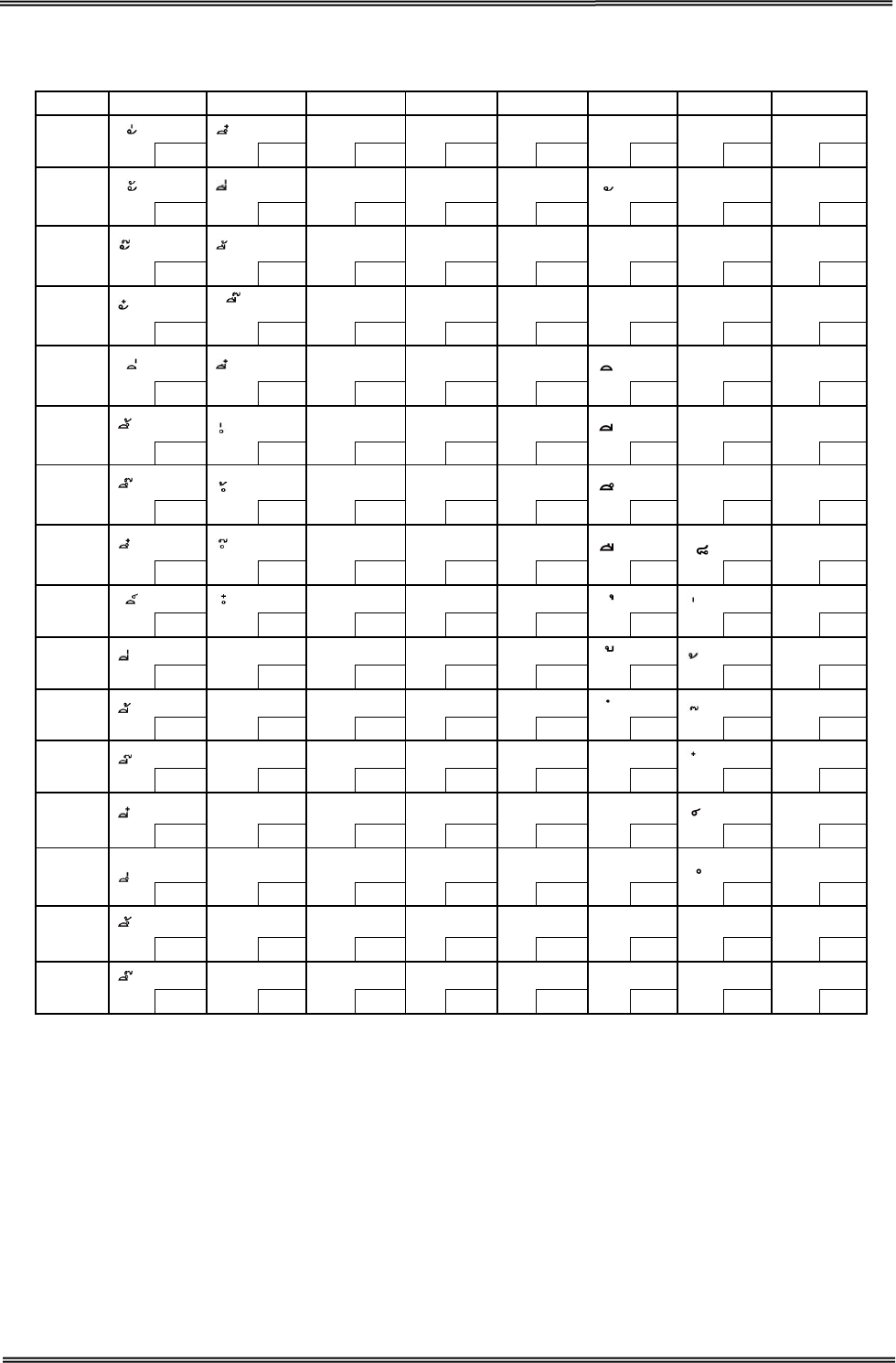
Tally Dascom DT-210/230 User Guide V1.3
77
8.13 [TIS11: Thai]
HEX 8 9 A B C D E F
0
เ
ฐ
ภ
ะ
เ
๐
128
144
160
176
192
208
224
240
1
ก
ฑ
ม
แ
๑
129 145
161
177
193
209
225
241
2
ข
ฒ
ย
า
โ
๒
130
146
162
178
194
210
226
242
3
ฆ
ณ
ร
า۫
ใ
๓
131 147
163
179
195
211
227
243
4
ค
ด
ฤ
ไ
๔
132
148
164
180
196 212
228
244
5
ฅ
ต
ล
ๅ
๕
133 149
165
181
197
213 229
245
6
ฆ
ถ
ฦ
ๆ
๖
134 150
166
182
198 214
230
246
7
ง
ท
ว
๗
135 151
167
183
199
215
231
247
8
จ
ธ
ศ
๘
136
152
168
184
200
216
232
248
9
┌
ฉ
น
ษ
๙
137
153
169
185
201
217 233
249
A
┐
ช
บ
ส
๚
138
154
170
186
202
218 234
250
B
└
ซ
ป
ห
─
๛
139
155
171
187
203
219
235
251
C
┘
ฌ
ผ
ฬ
┴
โ
140
156
172
188
204
220
236
252
D
│
ญ
ฝ
อ
┬
ใ
141
157
173
189
205
221
237
253
E
─
ฎ
พ
ฮ
┼
ε
ไ
142
158
174
190
206
222
238
254
F
├
ฏ
ฟ
ฯ۫
฿
๏
SP
143
159
175
191
207
223
239
255
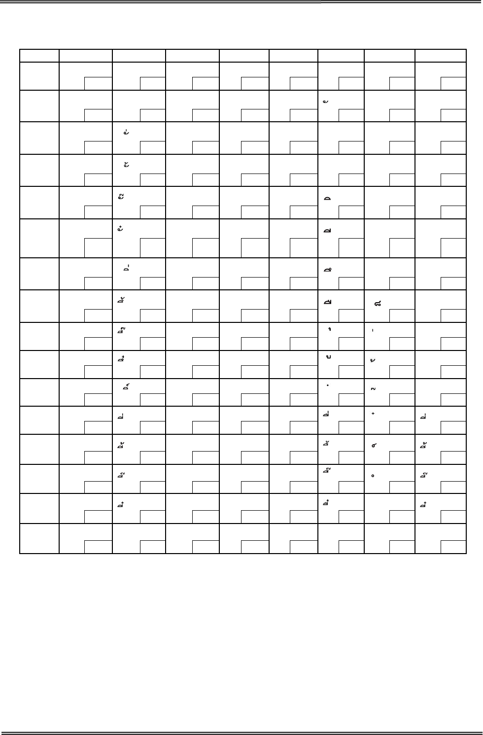
Tally Dascom DT-210/230 User Guide V1.3
78
8.14 [TIS18: Thai]
HEX 8 9 A B C D E F
0
┌
โ
SP
ฐ
ภ
ะ
เ
๐
128
144 160
176 192
208 224
240
1 ┐ ใ ก ฑ ม
แ
๑
129 145 161
177 193 209 225
241
2 └ ข ฒ ย า
โ
๒
130
146 162
178 194
210 226
242
3 ┘ ฃ ณ ร า۫
ใ ๓
131
147 163
179 195 211 227
243
4 │ ค ด ฤ
ไ
๔
132 148 164
180 196 212 228
244
5 ─ ฅ ต ล
ๅ ๕
133
149 165
181 197
213 229
245
6 ├ ฆ ถ ฦ
ๆ
๖
134
150 166
182 198 214 230
246
7 ┤ ง ท ว
๗
135
151 167
183 199 215
231
247
8
┴
จ ธ ศ
๘
136 152 168
184 200
216 232
248
9
┬
ฉ
น
ษ
๙
137
153 169
185 201
217 233
249
A
┼
ช
บ
ส
๛
138
154 170
186 202
218 234
250
B
█
ซ
ป
ห
139
155
171
187
203
219
235
251
C ←
ฌ ผ ฬ
140
156 172
188 204
220 236
252
D ↑
ญ ฝ อ
141 157 173
189 205 221 237 253
E →
ฎ พ ฮ ไ
142
158 174
190 206
222 238
254
F ↓ เ ฏ ฟ ฯ۫ ฿ ๏ SP
143
159
175
191
207
223
239
255
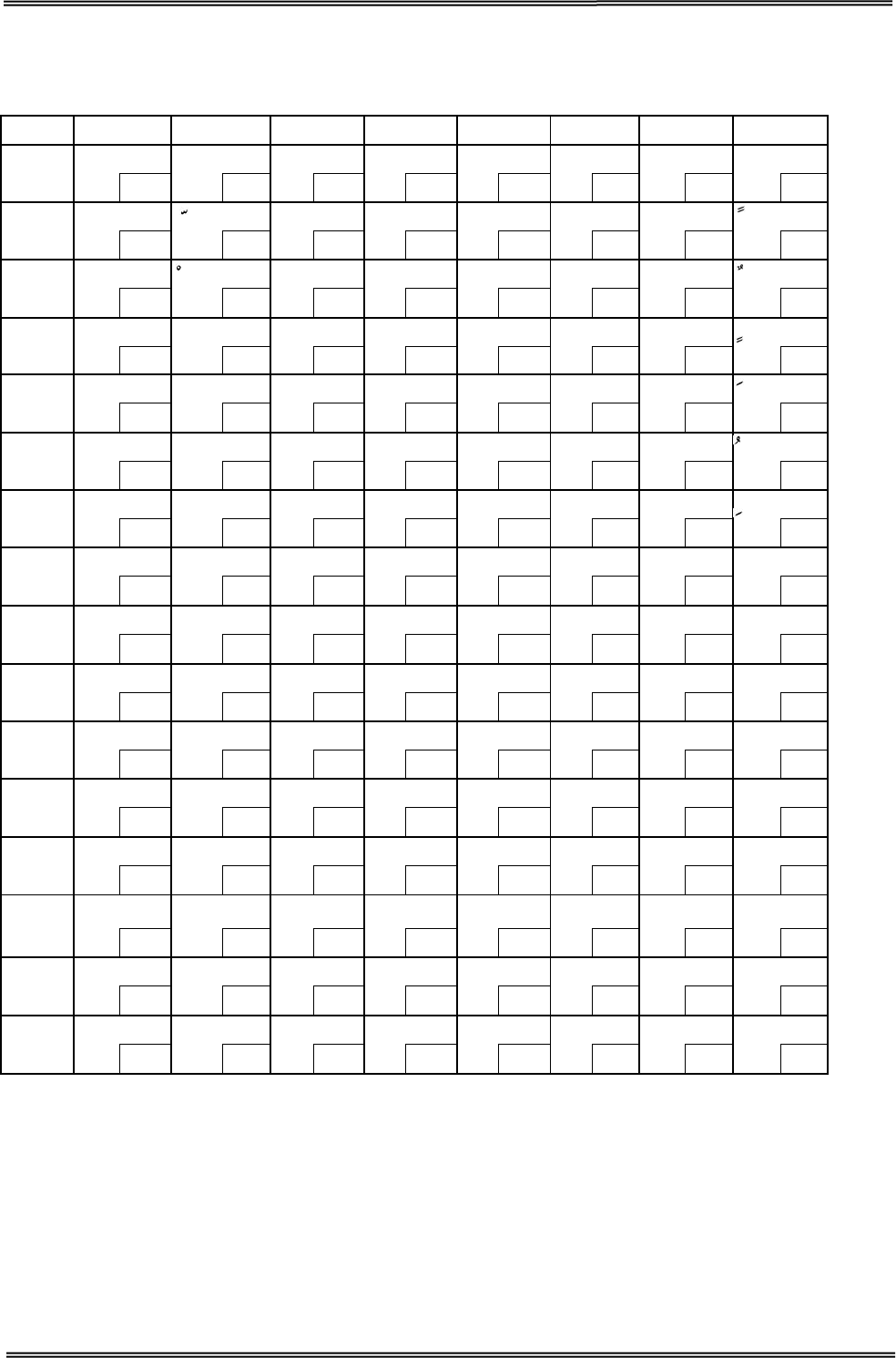
Tally Dascom DT-210/230 User Guide V1.3
79
8.15 [PC720: Arabic]
HEX 8 9 A B C D E F
0 SP SP
ب ░ └ ╨ ض ≡
128
144 160
176 192
208 224
240
1 SP
ة ▒ ┴ ╤ ط
129
145
161
177
193
209
225
241
2 é ت ▓ ┬
╥
ظ
130
146 162
178 194
210 226
242
3 a
ô ث │ ├
╙
ع
131 147 163
179 195 211 227 243
4 SP
¤ ج ┤ ─ ╘ غ
132
148
164
180
196
212
228
244
5
à
-
ح
╡
┼
╒
ف
133 149 165
181 197 213 229 245
6 SP
û خ ╢ ╞
╓
μ
134
150 166
182 198
214 230
246
7 ç
ù د ╖ ╟ ╫
ق ≈
135 151 167
183 199 215 231 247
8
ê
ء
ذ
╕
╚
╪
ك
°
136
152 168
184 200
216 232
248
9 ë
آ ر ╣ ╔ ┘ ل ·
137 153 169
185 201 217 233 249
A è
أ ز
║
╩
┌ م ·
138
154 170
186 202
218 234
250
B ï ؤ س ╗
╦
█
ن √
139 155 171
187 203 219 235 251
C î £ ش ╝ ╠ ▄ ه ⁿ
140
156 172
188 204
220 236
252
D SP
إ ص ╜ ╬ ▌ و 2
141 157 173
189 205 221 237 253
E SP
ئ « ╛ ╧
▐ ى ■
142
158 174
190 206
222 238
254
F SP
ا » ┐ SP
▀ ي SP
143 159 175
191 207 223 239 255
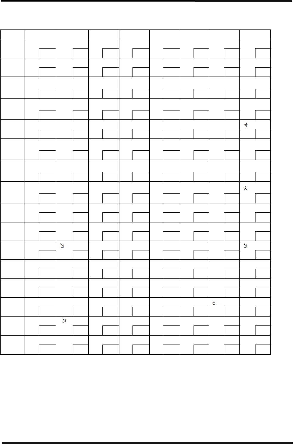
Tally Dascom DT-210/230 User Guide V1.3
80
8.16 [PC864: Arabic]
HEX 8 9 A B C D E F
0 ° β
SP ٠ ¢ ذ - ?
128
144 160
176 192
208 224
240
1 · ∞
١ ء ر ف ?
129 145 161
177 193 209 225 241
2 · φ آ ٢ آ ز ق ن
130
146 162
178 194
210 226
242
3 √ ± £ ٣ أ س ك ه
131 147 163
179 195 211 227 243
4 ▒ ½ ¤ ٤ ؤ ش ل
132
148 164
180 196
212 228
244
5 ─ ¼ أ ٥ ع ص م ى
133 149 165
181 197 213 229 245
6 │ ≈ SP ٦ ئ ض ن ي
134
150 166
182 198
214 230
246
7 ┼
« € ٧ ا ط ه
135 151 167
183 199 215 231 247
8 ┤ » ا ٨ ب ظ و ق
136
152 168
184 200
216 232
248
9 ┬ لأ ب ٩ ة ع ى لآ
137 153 169
185 201 217 233 249
A ├
ت
ف ت غ ي
138
154 170
186 202
218 234
250
B ┴ SP ث ؛ ث | ض ل
139 155 171
187 203 219 235 251
C ┐ SP ، س ج ¬ ع ك
140
156 172
188 204
220 236
252
D ┌ لا ج ش ح ÷
ي
141 157 173
189 205 221 237 253
E └ ا ح ص خ × غ ■
142
158 174
190 206
222 238
254
F ┘ ء خ ؟ د
ع م SP
143 159 175
191 207 223 239 255
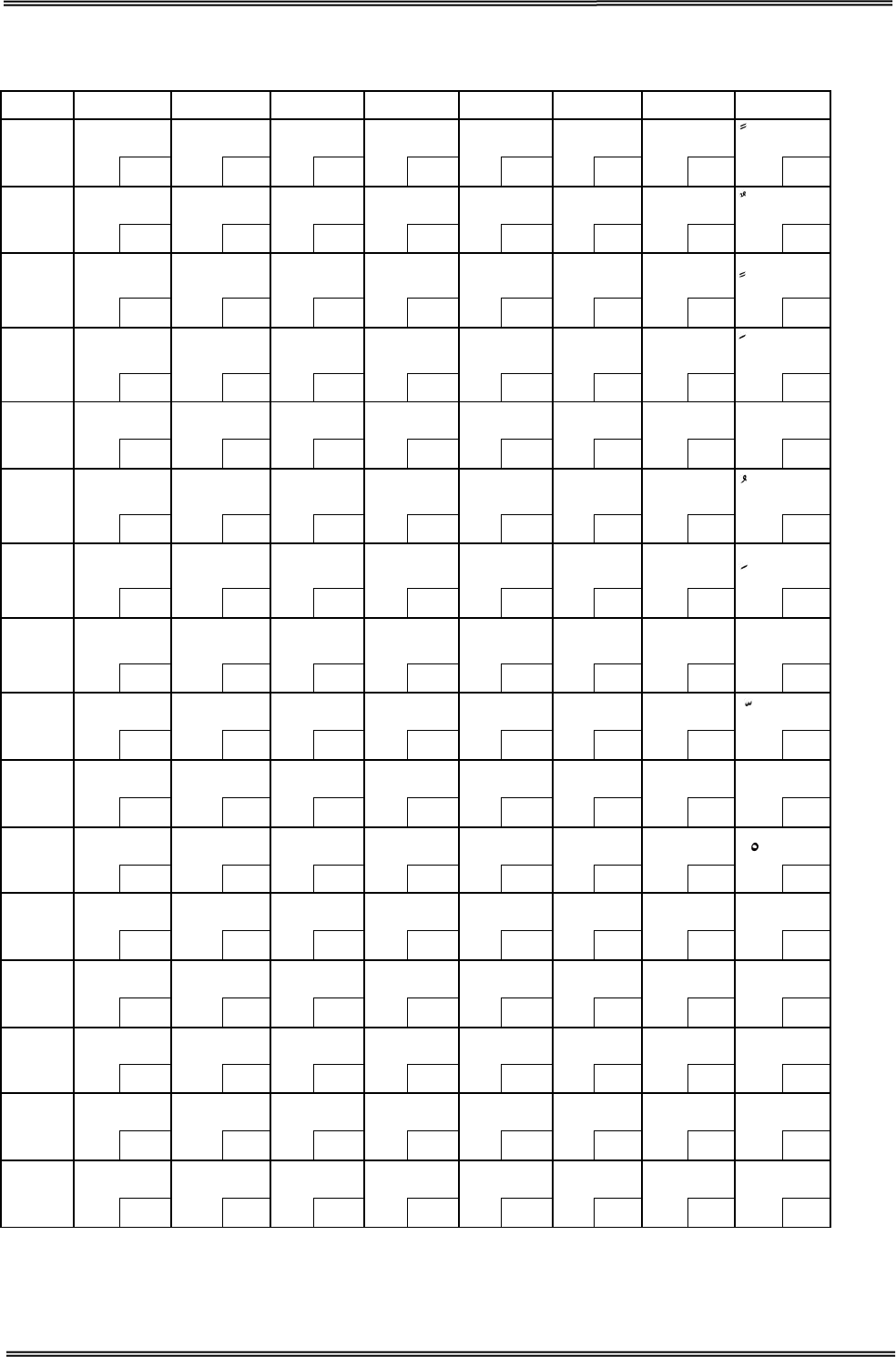
Tally Dascom DT-210/230 User Guide V1.3
81
8.17 [WPC1256: Arabic]
HEX 8 9 A B C D E F
0 € گ SP ° ہ ذ à
128
144 160
176 192
208 224 240
1
‚
‘
،
±
ء
ر
ل
129 145 161 177 193 209 225
241
2 پ ’ ¢ ² آ ز â
130
146 162
178 194
210 226 242
3 ƒ “ £ ³ أ س م
131 147 163 179 195 211 227 243
4 „ ” ¤ ´ ؤ ش ن Ô
132
148 164
180 196
212 228
244
5 … • ¥ μ إ ص ه
133 149 165 181 197 213 229 245
6 † – ¦ ¶ ئ ض و
134
150
166
182
198
214
230
246
7 ‡ — § · ا × ç ÷
135 151 167 183 199 215 231 247
8 ˆ ک ¨ ¸ ب ط è
136
152 168
184 200
216 232
248
9
‰
™
©
¹
ة
ظ
é
ù
137 153 169 185 201 217 233 249
A ٹ ڑ
ه ؛ ت ع ê
138
154 170
186 202
218 234
250
B ‹ › « » ث غ ë û
139 155 171 187 203 219 235 251
C Œ œ ¬ ¼ ج - ى ü
140
156 172
188 204
220 236
252
D چ SP
½ ح ف ي SP
141 157 173 189 205 221 237 253
E ژ SP ® ¾ خ ق î SP
142
158
174
190
206
222
238
254
F ڈ ں ¯ ؟ د
ك ï ے
143 159 175 191 207 223 239 255

Tally Dascom DT-210/230 User Guide V1.3
82
9 PRINTING CONTROL COMMAND SETS
· Be compatible with ESC/POS command set
· Support NV image and page mode printing
List of Commands
Command Name
HT
Horizontal tab
LF Print and line feed
FF
Print and return to standard mode (in page mode)
CR Print and carriage return
CAN
Cancel print data in page mode
DLE EOT Transmit real-time status
DLE ENQ Send real-time request to printer
DLE DC4
Generate pulse in real-time (fn = 1)
Execute power-off sequence (fn = 2)
Clear buffer(s) (fn = 8)
ESC FF Print data in page mode
ESC SP Set right-side character spacing
ESC !
Select print mode(s)
ESC $ Set absolute print position
ESC %
Select/cancel user-defined character set
ESC & Define user-defined characters
ESC
∗
Select bit-image mode
ESC
−
Turn underline mode on/off
ESC 2 Select default line spacing
ESC 3 Set line spacing
ESC = Select peripheral device
ESC ? Cancel user-defined characters
ESC @
Initialize printer
ESC D Set horizontal tab positions
ESC E Turn emphasized mode on/off
ESC G Turn double-strike mode on/off
ESC J Print and feed paper
ESC L
Select page mode
ESC M Select character font
ESC R Select an international character set
ESC S Select standard mode
ESC T Select print direction in page mode
ESC V
Turn 90 degrees clockwise rotation mode on/off
ESC W Set print area in page mode
ESC \ Set relative print position
Tally Dascom DT-210/230 User Guide V1.3
83
Command Name
ESC a Select justification
ESC c 3
Select paper sensor(s) to output paper-end signals
ESC c 4 Select paper sensor(s) to stop printing
ESC c 5
Enable/disable panel buttons
ESC d Print and feed n lines
ESC p Generate pulse
ESC t
Select character code table
ESC { Turn upside-down print mode on/off
FS g 1
Write to NV user memory
FS g 2 Read from NV user memory
GS ! Select character size
GS $
Set absolute vertical print position in page mode
GS ( A Execute test print
GS ( D
Enable/disable real-time command
GS ( E
Set user setup commands
<Function 1> Change into the user setting mode.
<Function 2> End the user setting mode session.
<Function 5> Set the customized setting values.
<Function 6> Transmit the customized setting values.
<Function 11> Set the configuration item for the serial interface.
<Function 12> Transmit the configuration item for the serial interface.
GS ( H
Request transmission of response or status
<Function 48> Set the process ID response.
GS ( K
Select print control method(s)
<Function 50> Select the print speed.
GS ( L / GS 8 L
Set graphics data
<Function 48> Transmit the NV graphics memory capacity.
<Function 50> Print the graphics data in the print buffer.
<Function 51> Transmit the remaining capacity of the NV graphics
memory.
<Function 64> Transmit the key code list for defined NV graphics.
<Function 65> Delete all NV graphics data.
<Function 66> Delete the specified NV graphics data.
<Function 67> Define the NV graphics data (raster format).
<Function 69> Print the specified NV graphics data.
<Function 112> Store the graphics data in the print buffer (raster format).
Tally Dascom DT-210/230 User Guide V1.3
84
Command Name
GS ( k
Set up and print symbol
<Function 065> PDF417: Set the number of columns in the data region.
<Function 066> PDF417: Set the number of rows.
<Function 067> PDF417: Set the width of the module.
<Function 068> PDF417: Set the row height.
<Function 069> PDF417: Set the error correction level.
<Function 070> PDF417: Select the options.
<Function 080> PDF417: Store the data in the symbol storage area.
<Function 081> PDF417: Print the symbol data in the symbol storage area.
<Fu
nction 082> PDF417: Transmit the size information of the symbol data in
the symbol storage area.
<Function 167> QR Code: Set the size of module.
<Function 169> QR Code: Select the error correction level.
<Function 180> QR Code: Store the data in the symbol storage area.
<Function 181> QR Code: Print the symbol data in the symbol storage
area. <Function 182> QR Code: Transmit the size information of the
symbol data in the symbol storage area.
GS
∗
Define downloaded bit image
GS /
Print downloaded bit image
GS : Start/end macro definition
GS B Turn white/black reverse print mode on/off
GS H Select print position of HRI characters
GS I Transmit printer ID
GS L
Set left margin
GS P Set horizontal and vertical motion units
GS V Select cut mode and cut paper
GS W Set print area width
GS \ Set relative vertical print position in page mode
GS ^
Execute macro
GS a Enable/disable Automatic Status Back (ASB)
GS f Select font for HRI characters
GS g 0 Initialize maintenance counter
GS g 2 Transmit maintenance counter
GS h
Set bar code height
GS k Print bar code
GS r Transmit status
GS w Set bar code width
FS p
Print NV bit image
FS q Define NV bit image
GS v 0
Print raster bit image
Tally Dascom DT-210/230 User Guide V1.3
85
The commands listed below in the first column are defined as “obsolete commands” in the ESC/POS
command system.
This printer supports both upward-compatible commands and obsolete commands. However, the
upward-compatible commands are recommended to use.
“Obsolete commands” are commands that are supported by legacy models;
however it is recommended to replace them with upward-compatible commands,
because they will not be supported in the future products.
Obsolete command Upward-compatible command
ESC i Partial cut (one point left uncut) GS V
ESC m
Partial cut (three points left uncut)
GS V
ESC u Transmit peripheral device status GS r
ESC v Transmit paper sensor status GS r
FS p
Print NV bit image
GS ( L <Function 69>
FS q Define NV bit image GS ( L <Function 67>
GS v 0
Print raster bit image
GS ( L <Function 112 + 50>
Tally Dascom DT-210/230 User Guide V1.3
86
FCC STATEMENT
1. This device complies with Part 15 of the FCC Rules. Operation is subject to the following two
conditions:
1) This device may not cause harmful interference.
2) This device must accept any interference received, including interference that may cause
undesired operation.
2. Changes or modifications not expressly approved by the party responsible for compliance could
void the user's authority to operate the equipment.
This equipment has been tested and found to comply with the limits for a Class B
digital device, pursuant to Part 15 of the FCC Rules. These limits are designed to
provide reasonable protection against harmful interference in a residential
installation.
This equipment generates uses and can radiate radio frequency energy and, if not installed and
used in accordance with the instructions, may cause harmful interference to radio communications.
However, there is no guarantee that interference will not occur in a particular installation. If this
equipment does cause harmful interference to radio or television reception, which can be
determined by turning the equipment off and on, the user is encouraged to try to correct the
interference by one or more of the following measures:
• Re-orientate or relocate the receiving antenna.
• Increase the separation between the equipment and receiver.
• Connect the equipment into an outlet on a circuit different from that to which the receiver
is connected.
• Consult the dealer or an experienced radio/TV technician for help.
RF warning for Mobile device:
This equipment complies with FCC radiation exposure limits set forth for an
uncontrolled environment. This equipment should be installed and operated with
minimum distance 20cm between the radiator & your body.

87
DASCOM REPRESENTATIVES
GERMANY
DASCOM Europe GmbH
Heuweg 3
D-89079 Ulm
Deutschland
Tel.: +49 (0) 731 2075 0
Fax: +49 (0) 731 2075 100
www.dascom.com
SINGAPORE (ASIA PACIFIC)
DASCOM AP Pte Ltd
21 Bukit Batok Crescent
#29-81, WCEGA To wer
Singapore 658065
Phone: +65 6760 8833
Fax: +65 6760 1066
www.dascom.com
AMERICAS
DASCOM Americas Corporation
24 Lakeview Court
Verona, VA 24482
USA
Phone:+1 (877) 434 13 77
Fax: +1 (540) 242 7221
www.dascom.com
UNITED KINGDOM
DASCOM GB Ltd
Hart House, Priestley Road
Basingstoke, Hampshire
RG24 9PU, England
Phone: +44 (0) 1256 481481
Fax: +44 (0) 1256 481400
www.dascom.com
FRANCE
DASCOM Europe GmbH
117 Avenue Victor Hugo
92100 Boulogne-Billancourt
France
Phone: +33 (1) 73 02 51 98
www.dascom.com
CHINA
JIANGMEN DASCOM COMPUTER
PERIPHERALS CO., LTD
No. 399, Jinxing Road, Jianghai District,
Jiangmen, Guangdong P.R. China
www.dascom.com.cn
“All rights reserved. Translations, reprinting or copying by any means of this manual complete or in
part or in any different form requires our explicit approval. We reserve the right to make changes to
this manual without notice. All care has been taken to ensure accuracy of information contained in
this manual. However, we cannot accept responsibility for any errors or damages resulting from
errors or inaccuracies of information herein.”
© 2015 DASCOM