Jinan USR IOT Technology WIFI232610 Serial to WiFi Adapter User Manual USR WIFI232 T
Jinan USR IOT Technology Limited Serial to WiFi Adapter USR WIFI232 T
Manual

Convert Server User Manual www.usr iot
.
c o
m
Jinan USR IOT Technology Limited 2
/
42 tec@usr.cn
Content
RS232/RS485 TO RJ45&WIFI CONVERT SERVER ............................................................................................ 1
1. Quick Start ........................................................................................................................................................... 4
1.1. Hardware connect .................................................................................................................................... 4
1.2. Network connection ................................................................................................................................. 4
1.3. Communication test ................................................................................................................................. 5
2. Introduction .......................................................................................................................................................... 6
2.1. Short Description ...................................................................................................................................... 6
2.2. Device Features ....................................................................................................................................... 7
2.3. Electronic Parameters .............................................................................................................................. 7
2.4. Packing Information ................................................................................................................................. 8
3. Hardware ............................................................................................................................................................. 9
3.1. Appearance size chart ............................................................................................................................. 9
3.2. Indicator Light ........................................................................................................................................... 9
3.3. Interface Instructions .............................................................................................................................. 10
4. Application .........................................................................................................................................................
11
4.1. Application of AP ....................................................................................................................................
11
4.2. Application of STA ..................................................................................................................................
11
4.3. Application of AP+STA ........................................................................................................................... 12
4.4. Wired and wireless Application drawing (Only 610 apply )............................................................... 13
4.5. Application of wireless serial port(one
AP,
one STA) ........................................................................... 14
5. Function Description ......................................................................................................................................... 15
5.1. User configuration process .................................................................................................................... 15
5.2. Working mode ........................................................................................................................................ 16
5.2.1. Transparent Transmission Mode ................................................................................................ 16
5.2.2. Serial command mode ................................................................................................................ 17
5.2.3. HTTPD Client mode .................................................................................................................... 18
5.3. WI-FI parameter setting ......................................................................................................................... 19
5.3.1. Auto- Frequency Function .......................................................................................................... 19
5.3.2. Security ........................................................................................................................................ 19
5.3.3. Search Function for STA ............................................................................................................. 19
5.3.4. Address Binding .......................................................................................................................... 20
5.4. UART Frame Scheme ............................................................................................................................ 20
5.4.1. UART Free-Frame ....................................................................................................................... 20
5.4.2. UART Auto-Frame ....................................................................................................................... 20
5.5. Network Setting ...................................................................................................................................... 21
5.5.1. Socket A ....................................................................................................................................... 21
5.5.2. Socket B ....................................................................................................................................... 21
5.6. New function ........................................................................................................................................... 22
5.6.1. TCP password authentication ..................................................................................................... 22
5.6.2. Upload ID ..................................................................................................................................... 22

Convert Server User Manual www.usr iot
.
c o
m
Jinan USR IOT Technology Limited 3
/
42 tec@usr.cn
5.6.3. Self-adaption Baudrate ............................................................................................................... 22
5.6.4. Keepalive ..................................................................................................................................... 23
5.6.5. Multiple
STA
parameters ............................................................................................................. 23
5.6.6. Websocket ................................................................................................................................... 23
5.7. Palmodic Signal ...................................................................................................................................... 24
5.8. Parameters Configuration ...................................................................................................................... 24
5.9. Firmware Upgrade ................................................................................................................................. 25
6. setup process .................................................................................................................................................... 25
6.1. Configuration via Web Accessing .......................................................................................................... 25
6.1.1. Open Web Management Interface ............................................................................................. 25
6.1.2. Quick Configure ........................................................................................................................... 26
6.1.3. Mode Selection Page .................................................................................................................. 27
6.1.4. AP Interface Setting Page ........................................................................................................... 28
6.1.5.
STA
Interface Setting Page ......................................................................................................... 28
6.1.6. Application Setting Page ............................................................................................................. 29
6.1.7. Ethernet Setting ........................................................................................................................... 31
6.1.8. HTTPD Client Mode .................................................................................................................... 31
6.1.9. Device Management Page ......................................................................................................... 32
Appendix A: Questions and Answers ................................................................................................................... 34
Q1: How to configure transparent serial port application (TCP protocol) with two Convert Servers? ...... 34
Q2: Where to Set WIFI Convert Server LAN IP and WAN IP through Web Page ?................................. 35
Q3: How to configure transparent serial port application (UDP protocol) with two Convert Servers? ...... 35
Q4: Where to set Convert Server network protocol (TCP/UDP)? ............................................................... 36
Q5: How to configure transparent serial port application: Two Convert Servers all configured as
STA
and
connection through AP? ................................................................................................................................ 37
Q6: How to avoid IP address confliction when apply Convert Server? ...................................................... 38
Q7: PC works as server, all Convert Servers works as data acquisition card and connect with PC, how to
configure this application? ............................................................................................................................. 38
Q8: Convert Server support UDP multicast? ............................................................................................... 40
Q9:Convert Server operates in
STA
mode, the PC how to get the IP Convert Server? ............................ 40
Appendix b: The FCC statement .......................................................................................................................... 41
Appendix c: Contact .............................................................................................................................................. 42
Appendix d: Disclaimer ......................................................................................................................................... 42
Appendix e: Update History .................................................................................................................................. 42
Convert Server User Manual www.usr iot
.
c o
m
Jinan USR IOT Technology Limited 4
/
42 tec@usr.cn
1.
1.
1.
1. Quick
Quick
Quick
Quick Start
Start
Start
Start
This chapter is the quick start for Convert Server . proposal user read this chapter and follow the instructions.
This will help your understanding of the product. Of course, the user can choose read chapters according to
need . For specific details and instructions, please refer to the following.
1.1.
1.1.
1.1.
1.1. Hardware
Hardware
Hardware
Hardware connect
connect
connect
connect
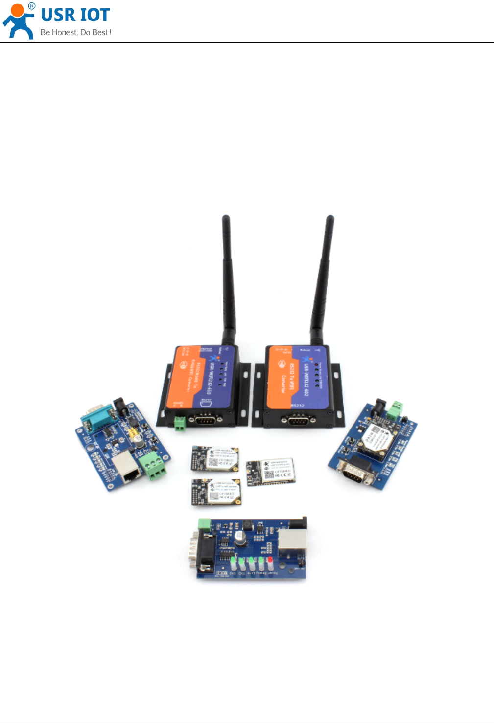
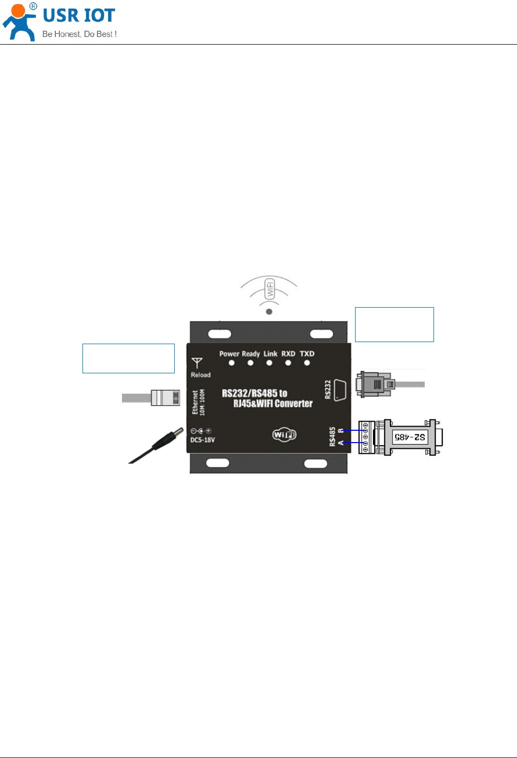
In order to test the serial port to the WIFI/ Ethernet communication transformation,connect the the device
serial port to PC serial port, connect the device WIFI/Ethernet to PC WIFI/Ethernet .If the desktop does not
own the serial port, also can use USB 232 to replace. The hardware environment.
Ethernet
DC
5 -
18
V
232
485
S
elect
Ethernet
or
WIFI
Select
232
or
485
Figure
Figure
Figure
Figure 1
1
1
1 Hardware
Hardware
Hardware
Hardware Connect(610)
Connect(610)
Connect(610)
Connect(610)
According to the above connect Convert Server.
1.2.
1.2.
1.2.
1.2. Network
Network
Network
Network connection
connection
connection
connection
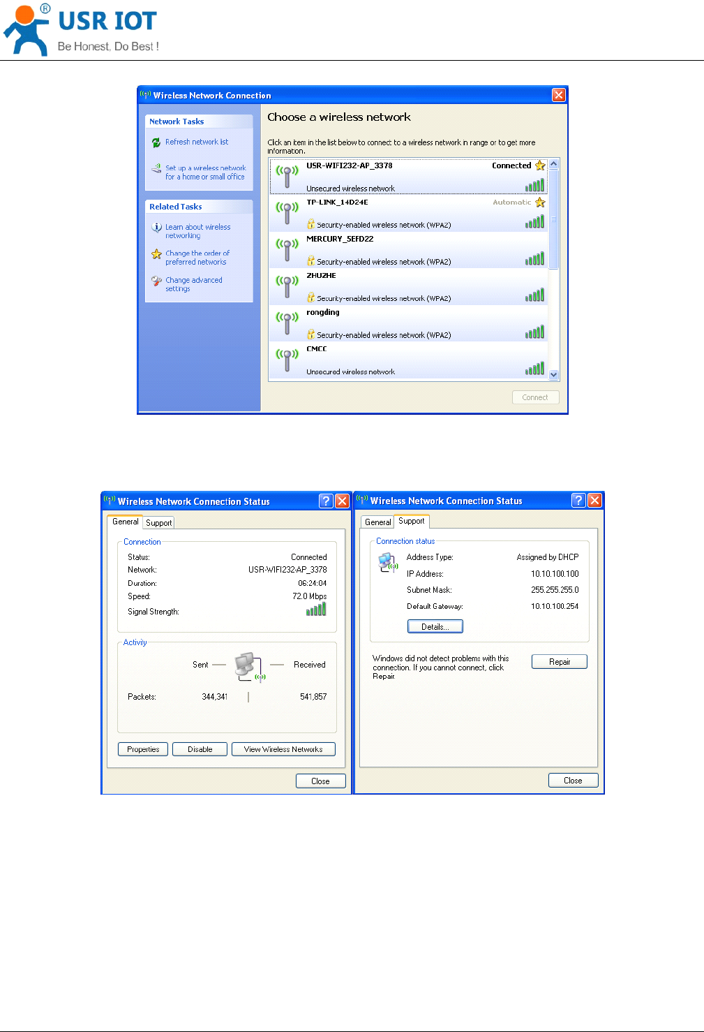
Open Wi-Fi, search network on the PC , as shown in below, USR-WIFI232- AP_3378 is the default network
name (SSID) of the Convert Server .
Note: if the firmware version is V4, the SSID is "HF - A11x_AP".After the SSID is also like this.
Convert Server User Manual www.usr iot
.
c o
m
Jinan USR IOT Technology Limited 5
/
42 tec@usr.cn
Figure
Figure
Figure
Figure 2
2
2
2 WIFI
WIFI
WIFI
WIFI Search
Search
Search
Search
Join the network, choose to automatically obtain
IP,
Convert Server supports DHCP Server feature and is
enabled by default.
Figure
Figure
Figure
Figure 3
3
3
3 WIFI
WIFI
WIFI
WIFI connection
connection
connection
connection
Now, link led of Convert Server is lighting.
1.3.
1.3.
1.3.
1.3. C
C
C
C ommunication
ommunication
ommunication
ommunication test
test
test
test
Convert Server ’s default setting:
SSID:
SSID:
SSID:
SSID: USR-WIFI232-D2_xxxx(xxxx is the last of mac address);
Encryption
Encryption
Encryption
Encryption mode
mode
mode
mode :
:
:
:open ,none ;
UART:
UART:
UART:
UART: 57600 ,8,1,None ;
Convert Server User Manual www.usr iot
.
c o
m
Jinan USR IOT Technology Limited 6
/
42 tec@usr.cn
Network
Network
Network
Network parameters
parameters
parameters
parameters :TCP,Server,8899,10.10.100.254 ;
IP:
IP:
IP:
IP: 10.10.100.254;
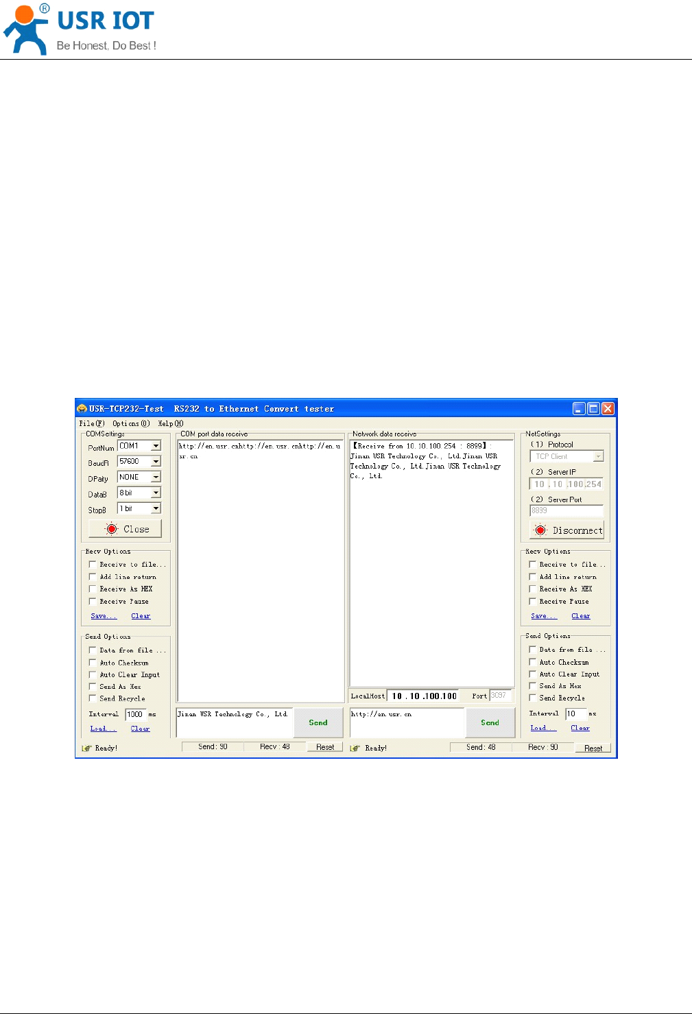
We just need to follow the parameters of the corresponding set of network communication parameters, you
can make serial < -- > WIFI or Ethernet communication, the steps are as follows:
1. Open test software USR-TCP232-Test ;
2. COM Settings area (left):
C hoose COM port witch has connect the Convert Server , there is COM3, choose band rate to 57600 , this is
the default band rate of Convert Server , Click Open COM port.
3. Net Settings area (right):
C hoose TCP client mode, Server IP write 10.10.100.254, it is the WIFI default IP address, Server port to 8899,
It is the default Port the Convert Server listen, Click Connect to link to the Convert Server .
Now, you can test send data between RS232 and WIFI.
COM port to WIFI: PC RS232 -> Convert Server RS232 -> Convert Server WIFI -> PC WIFI .
WIFI to COM port: PC WIFI or Ethernet -> Convert Server WIFI or Ethernet -> Convert Server RS232 -> PC
RS232.
Figure
Figure
Figure
Figure 4
4
4
4 serial
serial
serial
serial /
/
/
/ network
network
network
network transmission
transmission
transmission
transmission test
test
test
test
2.
2.
2.
2. Introduction
Introduction
Introduction
Introduction
2.1.
2.1.
2.1.
2.1. Short
Short
Short
Short Description
Description
Description
Description
Convert Server provides a serial port to WIFI function, can be RS-232/485 converted into a TCP/IP serial
network interface, RS-232/485 serial port and WIFI/ Ethernet bidirectional data transparent transmission. The
serial device can immediately with the TCP/IP network interface functions, connect to the network for data
Convert Server User Manual www.usr iot
.
c o
m
Jinan USR IOT Technology Limited 7
/
42 tec@usr.cn
communication, communication range extended serial device greatly.
Convert Server series currently has USR-WIFI232-610, USR-WIFI232-604,USR-WIFI232-602,
USR-WIFI232-2 lighting products. Specific parameters of each product please refer to below:
Table
Table
Table
Table 1
1
1
1 Product
Product
Product
Product model
model
model
model
T
ype RS232 RS485 Ethernet I nput
V
oltage Size(mm)
USR-WIFI232-610 YES YES YES 5-18V 84*84*25
USR-WIFI232-604 NO YES NO 5-9V 84*84*25
USR-WIFI232-602 YES NO NO 5-9V 84*84*25
USR-WIFI232-2 YES NO NO 5-9V 80*50*14 (No Shell )
2.2.
2.2.
2.2.
2.2. Device
Device
Device
Device Features
Features
Features
Features
Inner b oard core module specifications , please reference to USR-WIFI232-C
Support hardware flow control (RTS/CTS) RS232 interface, male mouth(needle) consistent with
computer pin definition
RS232 RS485 automatic switching (USR-WIFI232-610)
RJ45 network connection, support wired Ethernet transmission (USR-WIFI232-610)
Reload button, do not worry incorrect settings ( in working status, press the button 3 s then it load to
default s ettings and automatic restart)
Rich status indicator light : Power / Ready / Link / RXD / TXD
Pin 9 of the DB9 can be connected to p ower input (solder jumper on the back of PCB ), used for power
the sensor or the serial port cable power Convert Server .
D esign with positioning hole, convenient installation
H ighest support baud rate 460800 bps
optional TCP Server/TCP Client/UDP Client/ UDP Server mode, the TCP Server mode can support up to
32 Client connection
2.3.
2.3.
2.3.
2.3. E
E
E
E lectronic
lectronic
lectronic
lectronic P
P
P
P arameters
arameters
arameters
arameters
Table
Table
Table
Table 2
2
2
2 Electrical
Electrical
Electrical
Electrical parameter
parameter
parameter
parameter
Item Parameter
Wireless
parameter
Certification FCC/CE
Wireless
standard
802.11 b/g/n
Frequency range 2.412GHz-2.484GHz
Transmit power
802.11b: +20dBm(Max.)
802.11g: +18dBm(Max.)
802.11n: +15dBm(Max.)
Convert Server User Manual www.usr iot
.
c o
m
Jinan USR IOT Technology Limited 8
/
42 tec@usr.cn
configurable
Receiver
Sensitivity
802.11b: -89dBm
802.11g: -81dBm
802.11n: -71dBm
Antenna Option Externa l 3Dbi antenna
Hardware
Parameters
Data Interface
UART : 1200bps - 230400bps
Ethernet : 100Mpbs
GPIOs
Operating
voltage
5-18V (+/-5%)
Operating
current
170mA~300mA
Operating
temperature
-25 ℃- 85 ℃
Storage
temperature
-40 ℃- 125 ℃
Dimensions 83 × 80 × 25mm
Software
parameters
Network type Station/AP mode , STA+AP
Security
mechanisms
WEP/WPA-PSK/WPA2-PSK/WAPI
Encryption WEP64/WEP128/TKIP/AES
Work mode Transparent Transmission
Serial command AT+instruction set
Network
Protocol
TCP/UDP/ARP/ICMP/DHCP/DNS/HTTP
Max. TCP
Connection
32
User
Configuration
Web Server +
AT
command config
User Application
SW
Support customized application software
2.4.
2.4.
2.4.
2.4. Packing
Packing
Packing
Packing Information
Information
Information
Information
Convert Server *1
5V1A power adapt e r *1
Serial cable *1 (only USR-WIFI232-610)
Network cable *1 (only USR-WIFI232-610)
User guide CD *1 (only USR-WIFI232-610)
Convert Server User Manual www.usr iot
.
c o
m
Jinan USR IOT Technology Limited 9
/
42 tec@usr.cn
3.
3.
3.
3. Hardware
Hardware
Hardware
Hardware
3.1.
3.1.
3.1.
3.1. Appearance
Appearance
Appearance
Appearance size
size
size
size chart
chart
chart
chart
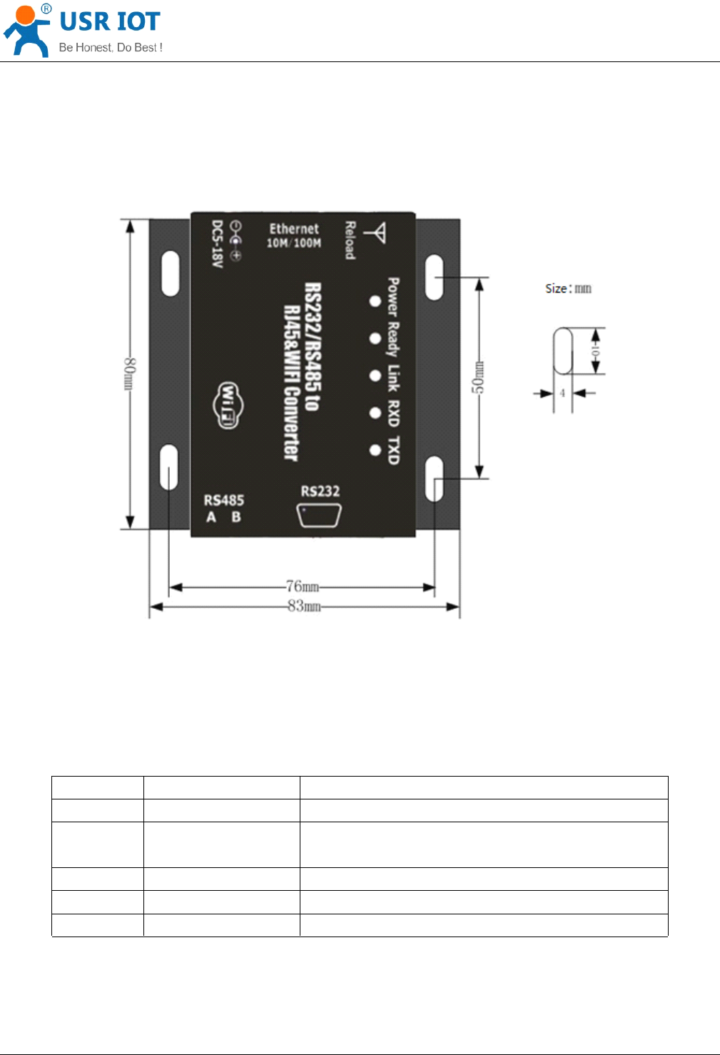
Figure
Figure
Figure
Figure 5
5
5
5 Appearance
Appearance
Appearance
Appearance size
size
size
size chart
chart
chart
chart (602/604/610)
(602/604/610)
(602/604/610)
(602/604/610)
3.2.
3.2.
3.2.
3.2. Indicator
Indicator
Indicator
Indicator L
L
L
L ight
ight
ight
ight
There are 5 lights in total, from left to right
Table
Table
Table
Table 3
3
3
3 Indicator
Indicator
Indicator
Indicator light
light
light
light
Indicator Function Description
Power power Keep light when power on
Ready Inner LINUX start Keep green light when connected to network
correctly
Link Network link Light when establish network link
TXD Transmit data Flash when send data
RXD Receive data Flash when receive data
Convert Server User Manual www.usr iot
.
c o
m
Jinan USR IOT Technology Limited 10
/
42 tec@usr.cn
3.3.
3.3.
3.3.
3.3. I
I
I
I nterface
nterface
nterface
nterface I
I
I
I nstructions
nstructions
nstructions
nstructions
Power
Power
Power
Power interface:
interface:
interface:
interface:
5.5*2.1 standard 5-18v power interface, with TVS protection
RS232
RS232
RS232
RS232 interface:
interface:
interface:
interface: (USR-WIFI232-610/
(USR-WIFI232-610/
(USR-WIFI232-610/
(USR-WIFI232-610/ 60
60
60
60 2/
2/
2/
2/ 2
2
2
2 )
)
)
)
Device serial port is male(needle), RS232 level (can connect to PC directly), pin order is consistent with PC
COM port. Use cross cable connected with PC(2-3cross,7-8cross, 5-5 direct, 7-8 can disconnect, but MUST
NOT connect with PC directly), There are 6 pins in work, others is NC.
Table
Table
Table
Table 4
4
4
4 RS232
RS232
RS232
RS232 P
P
P
P in
in
in
in s
s
s
s
ID NAME DESCRIPTION
2 RXD Receive data pin
3 TXD Send data pin
5 GND Data Ground
7 RTS Request to send
8 CTS Clear to send
9 VCC Can connect to Convert Server power input by join the PCB
jumper, default not connect.
RS485
RS485
RS485
RS485 interface:
interface:
interface:
interface: (USR-WIFI232-610/
(USR-WIFI232-610/
(USR-WIFI232-610/
(USR-WIFI232-610/ 60
60
60
60 4)
4)
4)
4)
R S 485 two wire links, A(DATA+), B(DATA-), when link to other RS485 device, A(+) to A(+), B(-) to B(-).
RJ45
RJ45
RJ45
RJ45 interface:
interface:
interface:
interface: (USR-WIFI232-610)
(USR-WIFI232-610)
(USR-WIFI232-610)
(USR-WIFI232-610)
Network port connection, Convert Server is 10M/100M adaptive, support AUTO MDI/MDIX, which means you
can use direct network cable to connect with PC also can be tested. Convert Server by default open , as
shown in the Convert Server specificatio n s.
Table
Table
Table
Table 5
5
5
5 RJ45
RJ45
RJ45
RJ45 Pins
Pins
Pins
Pins
ID TAB FUNCTION
1 TX+ Transceiver Data+
2 TX- Transceiver Data-
3 RX+ Receive Data+
4 PHY-VCC Transformer tap voltage
5 PHY-VCC Transformer tap voltage
6 RX- Receive Data-
7 n/c Not connected
8 n/c Not connected
Convert Server User Manual www.usr iot
.
c o
m
Jinan USR IOT Technology Limited
11 /
42 tec@usr.cn
Reload
Reload
Reload
Reload key:
key:
key:
key:
This key used for set up the Convert Server to factory setting, when Convert Server is working (Ready LED
on), press this key more than 1 seconds and free it, wait about 10 seconds until the Convert Server restart,
the green LEDs all off and then Ready LED on. Then the Convert Server goes to factory default settings.
4.
4.
4.
4. Application
Application
Application
Application
4.1.
4.1.
4.1.
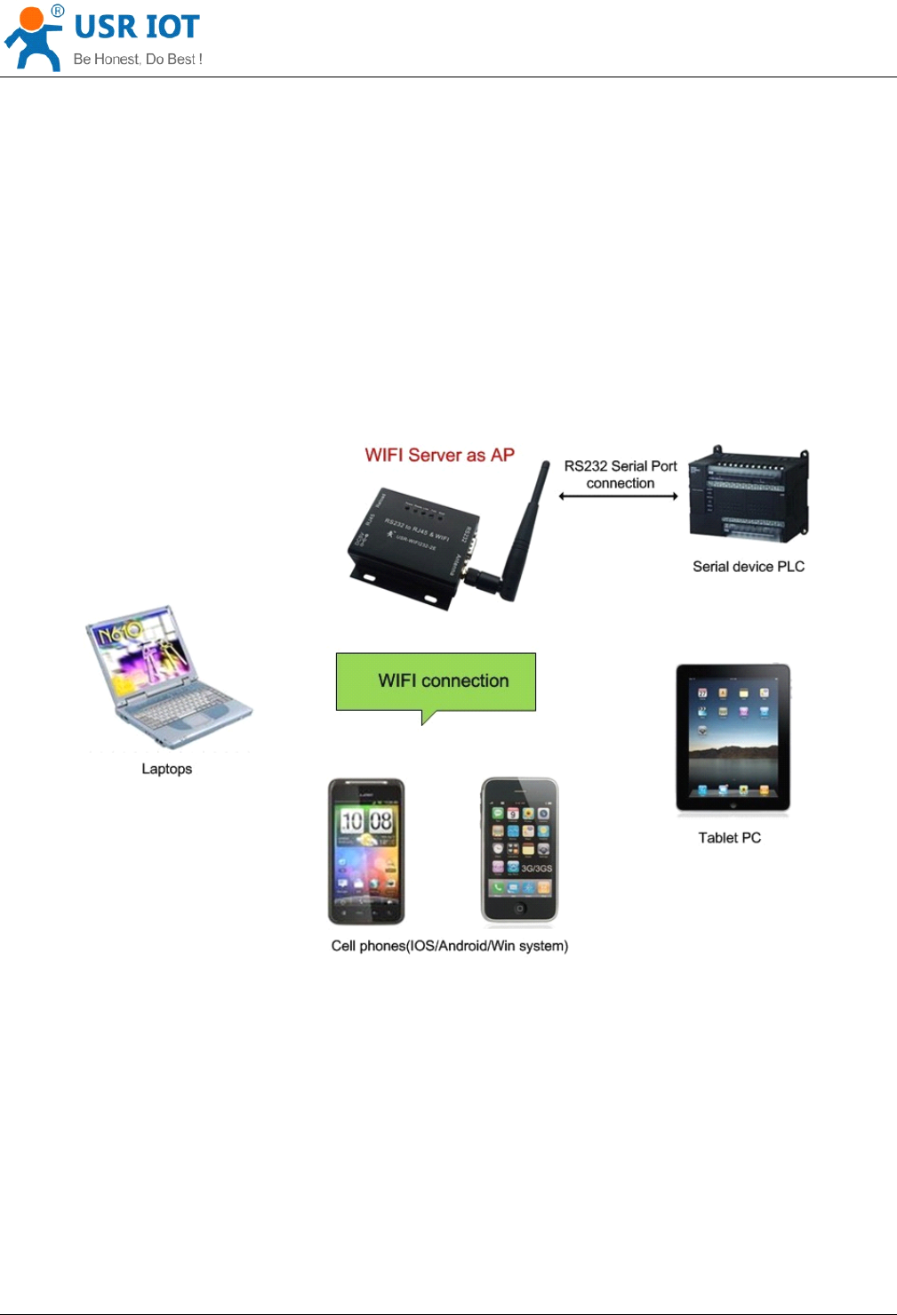
4.1. Application
Application
Application
Application of
of
of
of AP
AP
AP
AP
As shown in figure in, Convert Server used as an
AP,
all the other Convert Servers and computer can be used
as the
STA
to connect this Convert Server , at the same time it also can through the UART or GPIO interface
to the user equipment.
4.2.
4.2.
4.2.
4.2. Application
Application
Application
Application of
of
of
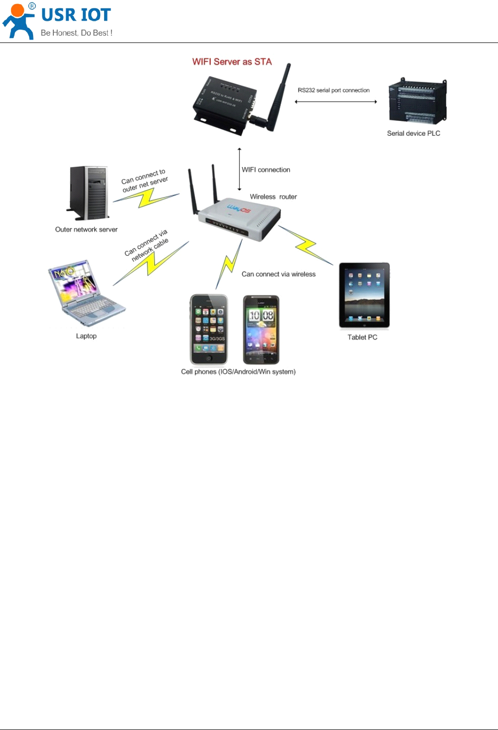
of STA
STA
STA
STA
Convert Server User Manual www.usr iot
.
c o
m
Jinan USR IOT Technology Limited 12
/
42 tec@usr.cn
Convert Server as STA(use the AP CLI interface), connect to other
AP,
to compose a wireless network. All of
the
STA
take AP as the wireless network center, and the mutual communication between
STA
is through AP
forwarding.
4.3.
4.3.
4.3.
4.3. Application
Application
Application
Application of
of
of
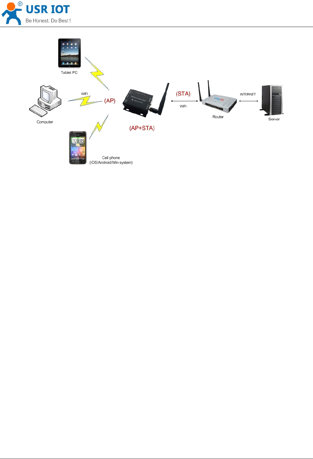
of AP+STA
AP+STA
AP+STA
AP+STA
Convert Server User Manual www.usr iot
.
c o
m
Jinan USR IOT Technology Limited 13
/
42 tec@usr.cn
Convert Server can support AP+STA mode. That is the Convert Server support a AP interface and a
STA
interface at the same time.
AP+STA function settings:
AP+STA function need to set through serial command.
AT+FAPSTA=on set AP+STA function
Then set Convert Server to
STA
mode, the AP interface still valid .
Note: the AT command part of this article is no longer in detail, please click the high-performance series
Convert Server specification.
4.4.
4.4.
4.4.
4.4. Wired
Wired
Wired
Wired and
and
and
and wireless
wireless
wireless
wireless Application
Application
Application
Application drawing
drawing
drawing
drawing (
(
(
(Only
Only
Only
Only 610
610
610
610 apply
apply
apply
apply )
)
)
)

Convert Server User Manual www.usr iot
.
c o
m
Jinan USR IOT Technology Limited 14
/
42 tec@usr.cn
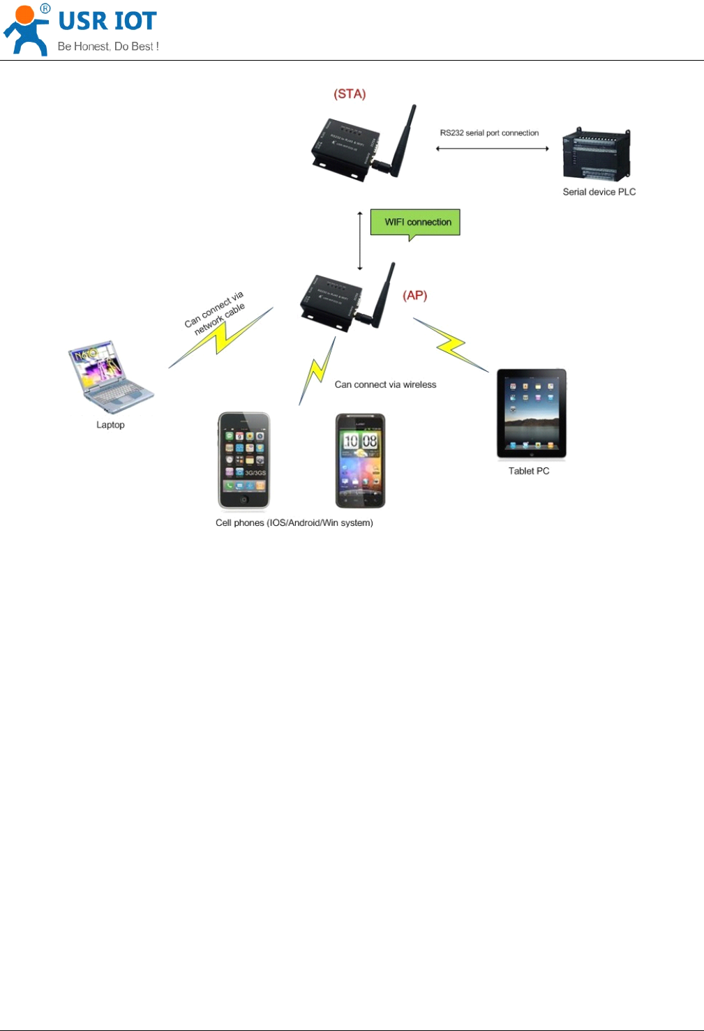
When USR-WIFI232- 610 used as
AP,
other computers and equipments can be used as
STA
connected to
this device through RJ45(network cable).
When USR-WIFI232- 610 used as STA, network port connected to computer via RJ45, wireless added to
wireless router to networking.
4.5.
4.5.
4.5.
4.5. Application
Application
Application
Application of
of
of
of wireless
wireless
wireless
wireless serial
serial
serial
serial port(one
port(one
port(one
port(one AP,
AP,
AP,
AP, one
one
one
one STA)
STA)
STA)
STA)
Convert Server User Manual www.usr iot
.
c o
m
Jinan USR IOT Technology Limited 15
/
42 tec@usr.cn
Convert Server can be set as
STA
or
AP.
So the device logically supports two wireless interfaces, one as STA,
another interface is equivalent to a
AP,
other STAs can connect to wireless network via the Convert Server AP
interface.
5.
5.
5.
5. F
F
F
F unction
unction
unction
unction D
D
D
D escription
escription
escription
escription
5.1.
5.1.
5.1.
5.1. User
User
User
User configuration
configuration
configuration
configuration process
process
process
process
After Convert Server electric starter, based on user pre-set parameters, automatically connect to wireless
networks and servers, and enter the working mode is set to open in accordance with the default serial port
parameters.
The parameters which need to configure include:
Wireless Network Parameters
Wireless Network Name (SSID )
Security Mode
Encryption Key

Convert Server User Manual www.usr iot
.
c o
m
Jinan USR IOT Technology Limited 16
/
42 tec@usr.cn
TCP/UDP Linking Parameters
Protocol Type
Link Type (Server or Client )
Target Port ID Number
Target Port IP Address
Serial Port Parameters
Baud Rate
Data Bit
Parity (Check) Bit
Stop Bit
Hardware Flow Control
Work Mode Selection
Transparent transmission /Serial command mode/GPIO mode/HTTPD Client mode
The following sections will introduce specific to each part in detail.
5.2.
5.2.
5.2.
5.2. Working
Working
Working
Working mode
mode
mode
mode
5.2.1.
5.2.1.
5.2.1.
5.2.1. Transparent
Transparent
Transparent
Transparent Transmission
Transmission
Transmission
Transmission Mode
Mode
Mode
Mode
Convert Server support serial interface transparent transmission mode. The benefit of this mode is achieves
a plug and play serial data port, and reduces user complexity furthest. In this mode, user should only
configure the necessary parameters. After power on, Convert Server can automatically connect to the default
wireless network and server.
As in this mode, the Convert Server 's serial port always work in the transparent transmission mode, so users
only need to think of it as a virtual serial cable, and send and receive data as using a simple serial. In other
words, the serial cable of users
’
original serial devices is directly replaced with the Convert Server ; user
devices can be easy for wireless data transmission without any changes.
The transparent transmission mode can fully compatible with user ’ s original software platform and reduce the
software development effort for integrate wireless data transmission.
Notes:
Notes:
Notes:
Notes: Users also open the serial port hardware flow control (CTS/RTS) function, so that we can make the bit
error rate to a minimum.If the user doesn't need hardware flow control function of the serial port, only need to
the corresponding pin foot (CTS/RTS) hung up.
Convert Server User Manual www.usr iot
.
c o
m
Jinan USR IOT Technology Limited 17
/
42 tec@usr.cn
5.2.2.
5.2.2.
5.2.2.
5.2.2. Serial
Serial
Serial
Serial command
command
command
command mode
mode
mode
mode
In this mode, the user can send the serial data to a different server address, this pattern can be use UDP or
TCP client sends data to the server.
Customer MCU send packets according to the following format, parsing Convert Server is finished, only the n
bytes of data sent to the destination address.When data is returned, not analytical data from serial port output
directly.
Table
Table
Table
Table 6
6
6
6 Protocol
Protocol
Protocol
Protocol table
table
table
table of
of
of
of Serial
Serial
Serial
Serial command
command
command
command mode
mode
mode
mode
frame
header
length functio
n
byte
Backup
data area
Destinati
on port
Target
address
Data Sum
check
2 2
(n+m+5)
1 2 2 m n 1
frame
frame
frame
frame header
header
header
header :
0x55 0xAA (Constant )
Length
Length
Length
Length :
Starting from the function byte, to Sum check (does not contain the sum check) all bytes. High byte at
the front
Function
Function
Function
Function byte
byte
byte
byte :
Bit0: (UDP:0 ;TCP:1 )
Bit1: (Short connection:0;Long connection:1 )
Bit2: (IP:0;Domain name:1 )
Bit7: (cut protocol:0;full protocol:1 )Note: currently only supports cut protocol
Notes:
Bit1:If it is a short connection, it sends data, and then will be disconnected; if it is long connection, it
sends data, connection will remain, until the re changing the target address.
Bit2:Indicates that the target address is
IP
or domain name. If it is
IP,
the target address is 4 bytes; if the
domain name, the target address length for the entire domain name string length (the last byte address is
‘ \0 ’ , that is the end of the string).
Bit7:Under the cut protocol, reply frame contains only data; Under the full protocol, reply frame has
"failed to send", "waiting for", "UDP radio response equipment IP" frame data.
Backup
Backup
Backup
Backup data
data
data
data area
area
area
area :
:
:
:
First byte:If it is a short connection, this position is TCP waits for the timeout time (1-255), if the send
command is completed, did not receive a response, then wait a few seconds and the corresponding, if 5,
said to wait for the 5S to disconnect; if the sending command, immediately receive the returned data,
then immediately disconnected; if it is long connection, this position is 0x00.
Second byte:Reserve
Destination
Destination
Destination
Destination port
port
port
port :
:
:
:
Little endian, low byte in the former,such as port 23, here are 0x17 0x00
Target
Target
Target
Target address:
address:
address:
address:
If it is
IP,
is 4 bytes, for example, 192.168.0.7 said 0x07 0x00 0xA8 0xC0; if it is a domain name, then the
address of indefinite length,ending with the ’ \0'.

Convert Server User Manual www.usr iot
.
c o
m
Jinan USR IOT Technology Limited 18
/
42 tec@usr.cn
Data:
Data:
Data:
Data:
Variable length,the maximum not exceeding 1000bytes.
Sum
Sum
Sum
Sum check:
check:
check:
check:
From the function word to check byte (does not contain a check byte), add Sum check.
The following is an example of a specific application:
send data:0x55 0xaa 0x00 0x0a 0x00 0x00 0x00 0x21 0x00 0x85 0x00 0xA8 0xC0 0x01 0x0f
Length:0x00 0x0a
Function byte:0x00 (UDP;Short connection;IP;cut protocol)
Destination port :0x21 0x00(33)
Target address: 0x85 0x00 0xA8 0xC0 (192.168.0.133)
Data:0x01(data length :1)
Sum check:0x0f ( 0x00+0x00+0x00+0x21+0x00+0x85+0x00+0xA8+0xC0+0x01=0x0f )
5.2.3.
5.2.3.
5.2.3.
5.2.3. HTTPD
HTTPD
HTTPD
HTTPD Client
Client
Client
Client mode
mode
mode
mode
This mode is used to send data to the HTTP server.
After setting the HTTP header format by webpage or
AT
command, the data sent each time by UART will add
the HTTP header automatically.Convenient for the user directly submit data or read data from the HTTP
server.
Below is the specific application, for example:
The first set HTTP parameters using AT instructions.
AT+HTTPURL=192.168.1.1,80 The serveraddress and portsettings
AT+HTTPTP=POST Set the HTTP type, GET, PUT or
POST
AT+HTTPPH=/set Set the path,the mostis50 bytes
AT+HTTPCN=keep-alive Set the Connection,maximum length
of 20bytes
AT+HTTPUA=lwip13.2 Set the User-Agent,maximum length
of 20bytes
If the sending data is 1234.In the 80 port of 192.168.1.1 will receive the following data
POST /set HTTP /1.1
Connection:keep-alive
User-Agent:lwip1.3.2
Content-Length:4
Host:192.168.1.1:80
1234
If the HTTP type is GET, the 80 port 192.168.1.1 receive data
POST /set 1234 HTTP /1.1
Connection:keep-alive
User-Agent:lwip1.3.2
Content-Length:0
Convert Server User Manual www.usr iot
.
c o
m
Jinan USR IOT Technology Limited 19
/
42 tec@usr.cn
Host:192.168.1.1:80
Data received from server will be directly sent to the serial port,without any treatment.
5.3.
5.3.
5.3.
5.3. WI-FI
WI-FI
WI-FI
WI-FI parameter
parameter
parameter
parameter setting
setting
setting
setting
5.3.1.
5.3.1.
5.3.1.
5.3.1. Auto-
Auto-
Auto-
Auto- Frequency
Frequency
Frequency
Frequency Function
Function
Function
Function
When Convert Server works as STA, Convert Server will adjust its wireless channel to keep the same
channel with associated AP and connect in.
When Convert Server works as AP and Convert Server enable Auto-frequency function, then when Convert
Server boot up, it will select the best wireless channel based on surrounding environment.
5.3.2.
5.3.2.
5.3.2.
5.3.2. Security
Security
Security
Security
Convert Server supports multiple wireless encryption mechanisms, and enables to protect the security of
user
’
s data transmission, the mechanisms include:
WEP
WPA-PSK/TKIP
WPA-PSK/AES
WPA2-PSK/TKIP
WPA2-PSK/AES
5.3.3.
5.3.3.
5.3.3.
5.3.3. Search
Search
Search
Search Function
Function
Function
Function for
for
for
for STA
STA
STA
STA
When using web configuration
STA
Interface Setting Page, user can push “ Search ” button to find surrounding
AP,
and find a AP to associated.
Figure
Figure
Figure
Figure 6
6
6
6 Search
Search
Search
Search page
page
page
page

Convert Server User Manual www.usr iot
.
c o
m
Jinan USR IOT Technology Limited 20
/
42 tec@usr.cn
5.3.4.
5.3.4.
5.3.4.
5.3.4. Address
Address
Address
Address Binding
Binding
Binding
Binding
Convert Server supports the feature of binding the BSSID address of target network.
According to the provisions of 802.11 protocol, different wireless networks can have a same network name
(i.e. SSID / ESSID), but must correspond to a unique BSSID address (i.e. MAC address). Illegal intruders can
create a wireless network with the same SSID / ESSID, it will make STAs in the network to join to the illegal
AP,
thereby and then network leakage happen.
Users can prevent
STA
from joining to illegal network by binding the BSSID address, to improve wireless
network security.
5.4.
5.4.
5.4.
5.4. UART
UART
UART
UART Frame
Frame
Frame
Frame Scheme
Scheme
Scheme
Scheme
5.4.1.
5.4.1.
5.4.1.
5.4.1. UART
UART
UART
UART Free-Frame
Free-Frame
Free-Frame
Free-Frame
Convert Server support UART free-frame function. If user select open this function, Convert Server will check
the intervals between any two bytes when rec ei ving UART data. If this interval time exceeds defined value
(50ms default), Convert Server will think it as the end of one frame and transfer this free-frame to WiFi port, or
Convert Server will receive UART data until 4K bytes, then transfer 4KB frame to WiFi port.
Convert Server ’ s default interval time is 50ms. User can also set this interval to fast (10ms) through
AT
command. But user have to consider if user MCU can send UART data with 10ms interval ,or the UART data
may be divide as fragment.
Through AT command: AT+FUARTTE=fas t /normal, user can set the interval time: fast (10ms) and normal
(50ms). This command is factory default setting command and AT+RELD can ’ t change its value.
5.4.2.
5.4.2.
5.4.2.
5.4.2. UART
UART
UART
UART Auto-Frame
Auto-Frame
Auto-Frame
Auto-Frame
Convert Server support UART auto-frame function. If user select open this function and setting auto-frame
trigger length and auto-frame trigger time parameters, then Convert Server will auto framing the data which
received from UART port and transmitting to the network as pre-defined data structure.
Auto-frame
Auto-frame
Auto-frame
Auto-frame trigger
trigger
trigger
trigger length:
length:
length:
length: The fixed data length that Convert Server used to transmitting to the
network.
Auto-frame
Auto-frame
Auto-frame
Auto-frame trigger
trigger
trigger
trigger time:
time:
time:
time: After the trigger time, if UART port received data can ’ t reach auto-frame
trigger length, then Convert Server will transmitting available data to the network and bypass the
auto-frame trigger length condition.
Convert Server User Manual www.usr iot
.
c o
m
Jinan USR IOT Technology Limited 21
/
42 tec@usr.cn
Detailed UART auto-frame function can refer to AT+ instruction set “ UARTF/UARTFT/UARTFL ” introduction.
5.5.
5.5.
5.5.
5.5. Network
Network
Network
Network Setting
Setting
Setting
Setting
Convert Server has two TCP/UDP Socket: Socket A and Socket B. Serial data written to the Convert Server ,
will be sent to the Socket
A
and B simultaneously; TCP/UDP data that Convert Server receives through either
Socket
A
or B,will be sent to the serial port.
Dual Socket through different settings, you can achieve a variety of network interconnect. When the Convert
Server shipped only open Socket A, Socket B default is not to connect, if the user needs to use, please set by
AT
commands.
5.5.1.
5.5.1.
5.5.1.
5.5.1. Socket
Socket
Socket
Socket A
A
A
A
Socket
A
has three work mode: TCP Server, TCP Client, UDP.The setting method, please refer to the
AT+NETP command instruction.
When Socket
A
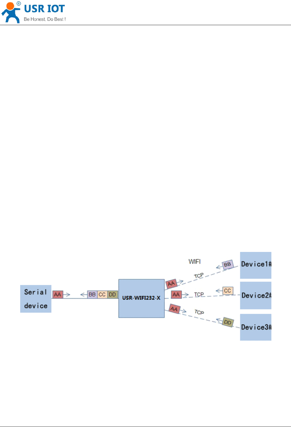
configured as TCP Server, it supports Multi-TCP link connection, and maximum 32 TCP
clients permitted to connect to Socket A.
Multi-TCP link connection will work as following structure:
Upstream: All dates from different TCP connection or client will be transmitted to the serial port as a
sequence.
Downstream: All data from serial port (user) will be duplicate and broadcast to every TCP connection or
client.
Detailed multi-TCP link data transmition structure as following figure:
Figure
Figure
Figure
Figure 7
7
7
7 Multi-TCP
Multi-TCP
Multi-TCP
Multi-TCP Link
Link
Link
Link Data
Data
Data
Data Transmition
Transmition
Transmition
Transmition Structure
Structure
Structure
Structure
5.5.2.
5.5.2.
5.5.2.
5.5.2. Socket
Socket
Socket
Socket B
B
B
B
Socket B has one work mode: TCP Client, please refer to the
AT
+ SOCKB command instruction.
With variety work mode, socket B can provide users with flexible data transfer methods.For example, Socket
B can connect to a remote server in order to achieve remote control.

Convert Server User Manual www.usr iot
.
c o
m
Jinan USR IOT Technology Limited 22
/
42 tec@usr.cn
5.6.
5.6.
5.6.
5.6. New
New
New
New function
function
function
function
This chapter is based on the function of V4.02.10.USR13 and above, if not this version you can skip this
section.
5.6.1.
5.6.1.
5.6.1.
5.6.1. TCP
TCP
TCP
TCP password
password
password
password authentication
authentication
authentication
authentication
This feature is available only on the Convert Server as a TCP server, when the TCP client connection Convert
Server , the Convert Server will authenticate each connected tcp.
Each TCP client first data is the “ password +0x0d+0x0a ” (the password is Webpage authentication password).
The default password is “ admin ” , so the first piece of data should be "0x61 0x64 0x6D 0x69 0x6E 0x0D 0x0A"
( Hex ). If the password is correct, the Convert Server returns "OK", on the other hand, return to the "NO" and
disconnect.
The TCP connection of this function can be Webpage in "TCP connection password authentication" is
opened or disable. Please refer to the specific "5.1.2" section.
5.6.2.
5.6.2.
5.6.2.
5.6.2. Upload
Upload
Upload
Upload ID
ID
ID
ID
This function only applies to the Convert Server as a TCP client, in front of the data when Convert Server
connected to the server with two bytes of ID (ID the range is 0 ~ 65535, the high byte before, and the low byte
behind) plus two bytes ID radix-minus-one complement. Convert Server is the default ID is
1111,
for example,
is sent to the server when the first four bytes "0x57 0x04 0xfb 0 xa8".
There are two ways to upload their own id: one is to upload their own id for connection to the server for the
first time;The other is a plus id in front of each data.
ID number related parameter is set in the "serial port and other Settings" section of the web, build joint
function of ID for the first time, and each data with the function of ID are opened by default.
ID can also use the at command to set the related parameters, specific refer to 5.2.1.4.32-5.2.1.4.34 section.
5.6.3.
5.6.3.
5.6.3.
5.6.3. S
S
S
S elf-adaption
elf-adaption
elf-adaption
elf-adaption Baudrate
Baudrate
Baudrate
Baudrate
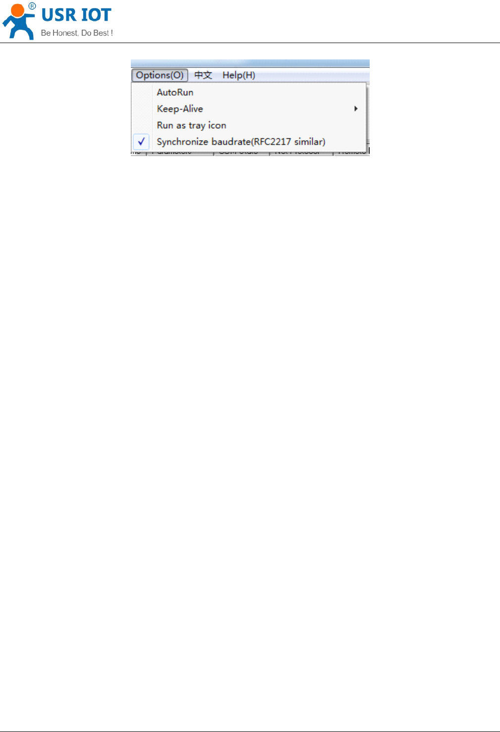
This feature, please cooperate with our company's virtual serial port software use.
Use a serial port connected Convert Server , and use the at command "at + AABR = on" open this function
and restart.In the USR - VOCM software "synchronous baud rate (RFC2217 similar )" is selected, the
following figure .
Convert Server User Manual www.usr iot
.
c o
m
Jinan USR IOT Technology Limited 23
/
42 tec@usr.cn
Figure
Figure
Figure
Figure 8
8
8
8 RFC
RFC
RFC
RFC 2217
2217
2217
2217
In this way, the Convert Server of baud rate will be as the USR-VCOM to change at any time, and don't have
to restart the Convert Server .If restart the Convert Server , baud rate and will come back to before.
5.6.4.
5.6.4.
5.6.4.
5.6.4. Keepalive
Keepalive
Keepalive
Keepalive
V4.02.10. USR13 and above version of the firmware added keepalive when the TCP connection mechanism,
so when the Convert Server of network anomalies, timely diagnose abnormal to the network and disconnect,
when the network has resumed after, and just in time to connect to the server.
5.6.5.
5.6.5.
5.6.5.
5.6.5. Multiple
Multiple
Multiple
Multiple STA
STA
STA
STA parameters
parameters
parameters
parameters
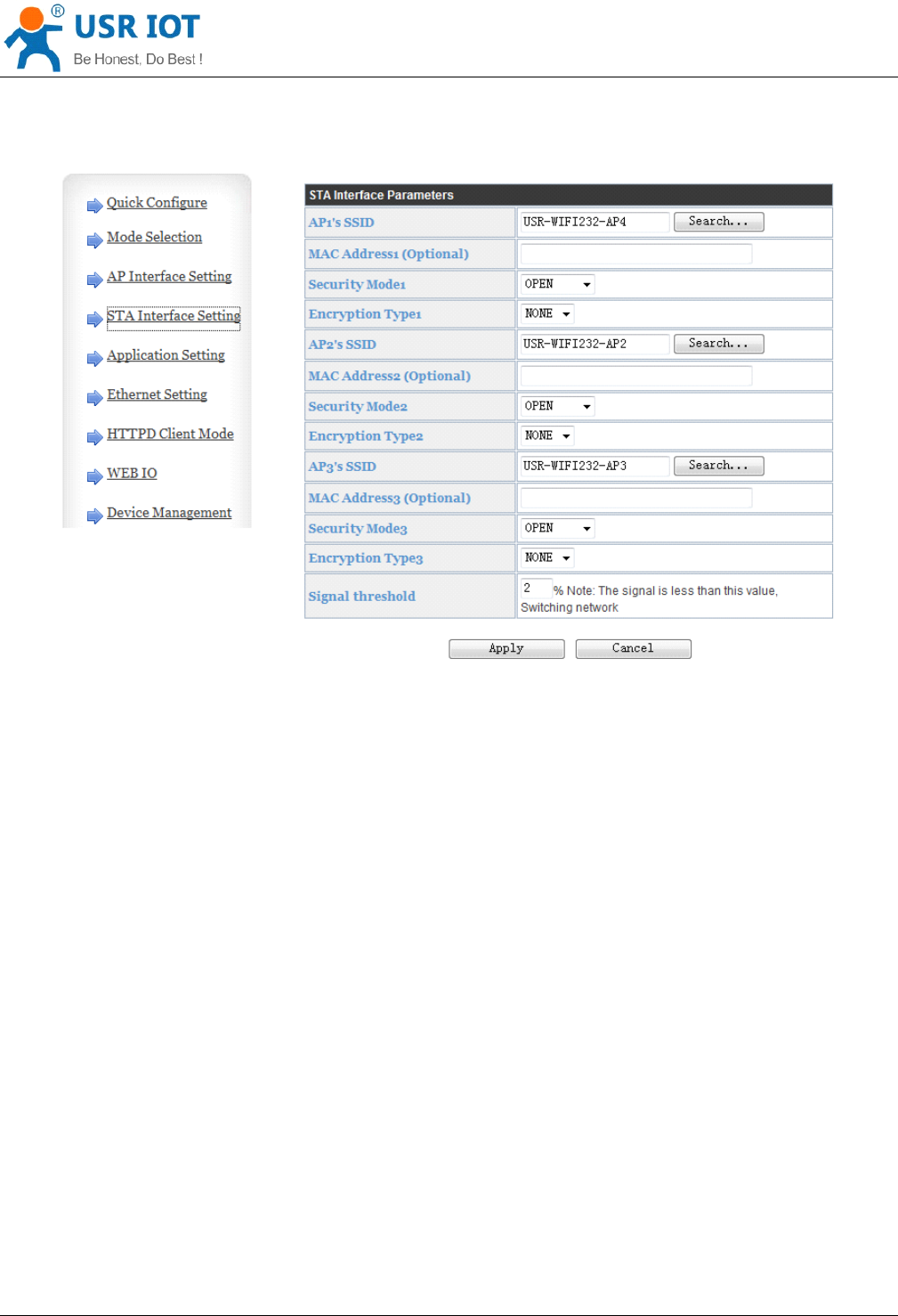
This function based on V4.02.10.USR18 and above version of the firmware, in the sta mode, if can network
signal is too low, it will automatically switch to the other AP network (switching network automatically restart).
This feature provides a signal threshold, when the current network signals is lower than the critical value, the
Convert Server of automatic switching network and restart.If the signal value is set to 100, the Convert Server
will not switch network.Even if the current network signal is not the current network will always search, not
heavy to other networks.
The function of the specific Settings page refer to section 4.5.4.
5.6.6.
5.6.6.
5.6.6.
5.6.6. Websocket
Websocket
Websocket
Websocket
This Convert Server can realize the function of the websocket server, allowing serial real-time interaction with
the web Convert Server, replace the previous HTTP GET, POST, corresponding faster.This Convert Server
provides the corresponding websocket test page for user testing, specific page is as follows:(web
Page:10.10.100.254/websocketen.html)

Convert Server User Manual www.usr iot
.
c o
m
Jinan USR IOT Technology Limited 24
/
42 tec@usr.cn
Figure
Figure
Figure
Figure 9
9
9
9 Websocket
Websocket
Websocket
Websocket Page
Page
Page
Page
Click on the "connect" page and then implements a connection, so a serial port with page can send or receive
data from each other.This Convert Server websocket server support 8 client connection at the same time.
This function for web applications, and for web users with higher response speed, if you want to customize
the corresponding web page, can connect your company.
5.7.
5.7.
5.7.
5.7. Palmodic
Palmodic
Palmodic
Palmodic Signal
Signal
Signal
Signal
Base on selected factory default setting, “ Ready ” signal can have two output statuses:
Status One: The Convert Server will output “0”after normal boot up. This signal used to judge if
Convert Server finish boot up and ready for application.
Status Two: The Convert Server will output “Palmodic Signal ”after normal boot up.The palmodic signal
is 0.5Hz square wave with dutyfactor 1:1. User can query this signal to judge if Convert Server is active
“live ”or need to re-boot. When Convert Server switches to command mode, it will output “0”, which
used to distinguish work mode and command mode.
Notes:
This function is user selected factory setting and RELD instruction will not effective for this function. If user not
requires this function, the default factory setting is Status One. Contact with USR Technology for more
detailed support.
5.8.
5.8.
5.8.
5.8. Parameters
Parameters
Parameters
Parameters Configuration
Configuration
Configuration
Configuration
Convert Server Convert Server support s two methods to configuration parameters: Web
Web
Web
Web Accessing
Accessing
Accessing
Accessing and
AT+instruction
AT+instruction
AT+instruction
AT+instruction set.
set.
set.
set.
Web accessing means users can configure parameters through built-in webpage. When Convert Server
Convert Server connected to wireless network, parameters configuration is done on a PC connected to the
Convert Server User Manual www.usr iot
.
c o
m
Jinan USR IOT Technology Limited 25
/
42 tec@usr.cn
same wireless network. AT+instruction set configuration means user configure parameters through serial
interface command. Refer to “ AT+instruction set ” chapter for more detail.
Notes:
Notes:
Notes:
Notes:
USR can customized the parameters setting as customer request and ship Convert Server with these
parameters as factory default configuration. It will reduce user ’ s Convert Server configuration time for mass
production. Also, if user need different parameters setting for every Convert Server , USR can provide the
auto-configuration tool to speed up the Convert Server con fi guration duration. Please contact USR technical
interface to acquire this tool if required.
5.9.
5.9.
5.9.
5.9. Firmware
Firmware
Firmware
Firmware Upgrade
Upgrade
Upgrade
Upgrade
Convert Server supports firmware upgrade online .
6.
6.
6.
6. setup
setup
setup
setup process
process
process
process
6.1.
6.1.
6.1.
6.1. Configuration
Configuration
Configuration
Configuration via
via
via
via Web
Web
Web
Web Accessing
Accessing
Accessing
Accessing
When first use Convert Server s, user may need some configuration. User can connect to Convert Server ’ s
wireless interface with following default setting information and configure the Convert Server through laptop.
Web Access Default Setting
Parameters
Parameters
Parameters
Parameters Default
Default
Default
Default Setting
Setting
Setting
Setting
SSID USR-WIFI232-A P_xxxx
IP Address 10.10.10 0 .254
Subnet Mask
255.255.255.0
User Name
admin
Password admin
6.1.1.
6.1.1.
6.1.1.
6.1.1. Open
Open
Open
Open Web
Web
Web
Web Management
Management
Management
Management Interface
Interface
Interface
Interface
Step 1: Connect laptop to SSID “ USR-WIFI232-AP_xxxx ” of Convert Server via wireless LAN card;
Step 2: After wireless connection OK. Open browser and access “ http://10.10.100.254
http://10.10.100.254
http://10.10.100.254
http://10.10.100.254 ” ;
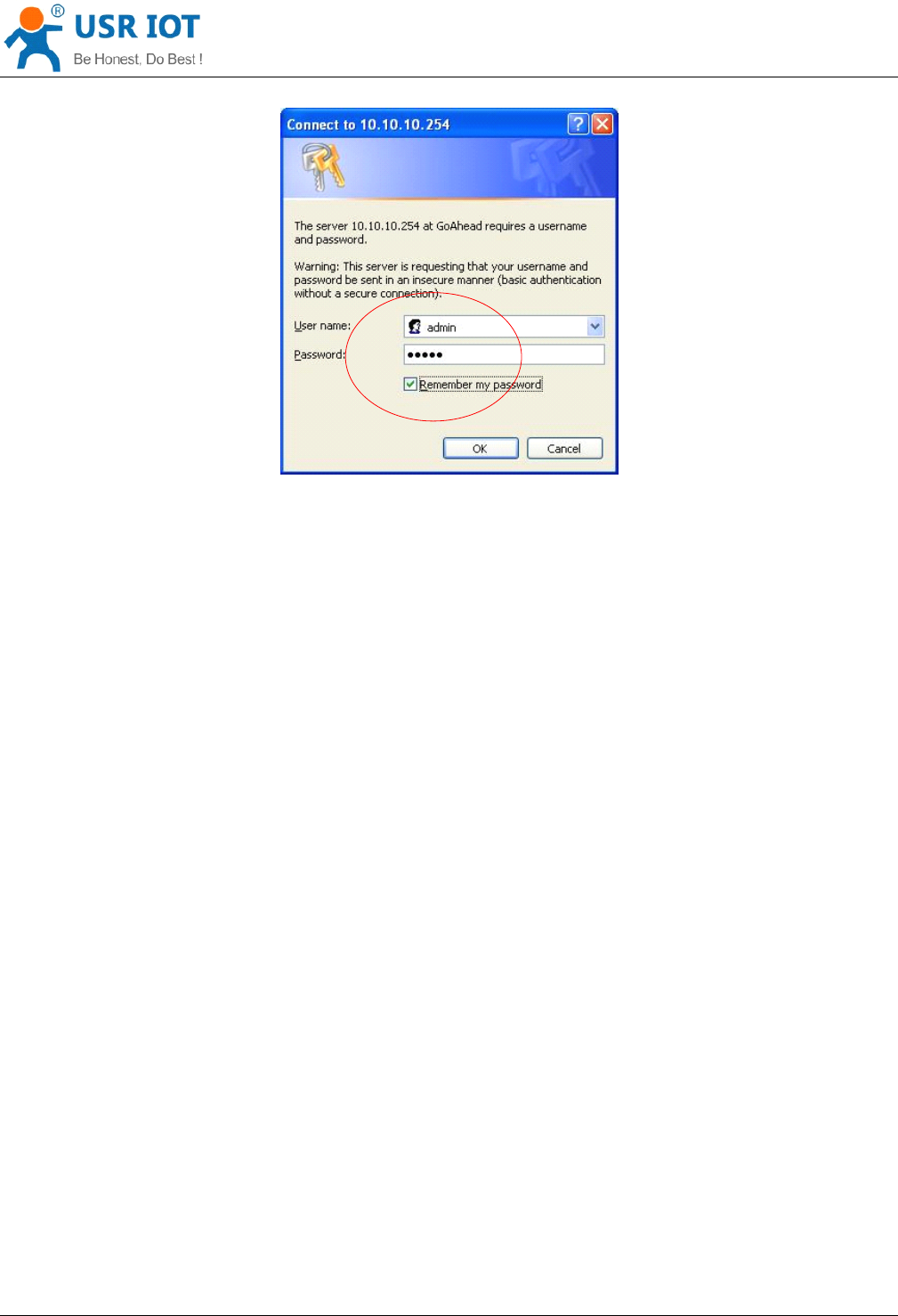
Step 3: Then input user name and password in the page as following and click “ OK ” button.
Convert Server User Manual www.usr iot
.
c o
m
Jinan USR IOT Technology Limited 26
/
42 tec@usr.cn
Figure
Figure
Figure
Figure 10
10
10
10 Open
Open
Open
Open Web
Web
Web
Web Management
Management
Management
Management page
page
page
page
The Convert Server web management page support English and Chinese language. User can select
language environment at the top right corner and click “ Apply ” button.
The main menu include nine pages: “ Quick Configure ” , “ Mode Selection ” , ” AP Interface Setting ” , ”
STA
Interface Setting ” , ” Application Setting ” , “ Ethernet Setting ” , ’’ HTTPD Client m ode ” , “ WEB IO ” and “ Device
Management ” .
6.1.2.
6.1.2.
6.1.2.
6.1.2. Quick
Quick
Quick
Quick Configure
Configure
Configure
Configure
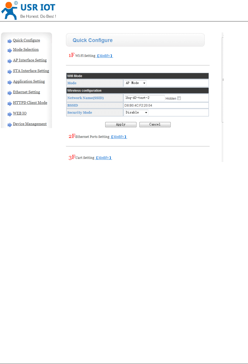
This page provides users with a method of rapid configuration Convert Server.Users according to the steps to
configure the parameters and restart the Convert Server page, you can let the Convert Server is normal work,
reduced the configuration steps and time.Of course the options on this page is less, if some detailed
configuration, still need to the corresponding configuration page.
Convert Server User Manual www.usr iot
.
c o
m
Jinan USR IOT Technology Limited 27
/
42 tec@usr.cn
Figure
Figure
Figure
Figure 11
11
11
11 Quick
Quick
Quick
Quick Configure
Configure
Configure
Configure Page
Page
Page
Page
This page has four configuration options and a restart, the corresponding instructions below:
WI-FI Setting: set the working mode of wifi, AP mode or the STA.
Ethernet Ports Setting: open/close the Ethernet ports, and set up the corresponding work mode.
UART Setting: set serial port parameters, including baud rate, parity bit, 485 functions and so on.
Network Setting: set network parameters, Only TCPA related parameters.
Device Management: when after completion of the above parameters are configured, click reset Convert
Server.
6.1.3.
6.1.3.
6.1.3.
6.1.3. Mode
Mode
Mode
Mode Selection
Selection
Selection
Selection Page
Page
Page
Page
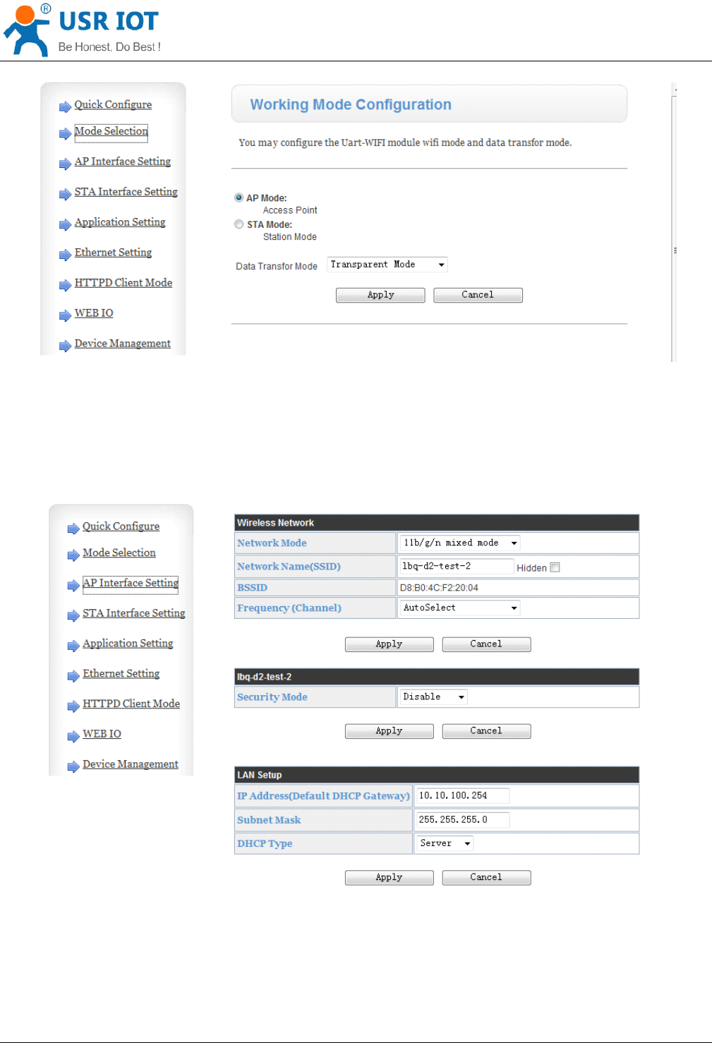
This page use to setting the wireless networking mode (AP and
STA
mode).
"Data transmission mode" selection Convert Server working mode are "Transparent Mode", "Serial Command
mode", "GPIO mode" and ”” HTTPD-Client Mode ” .
Convert Server User Manual www.usr iot
.
c o
m
Jinan USR IOT Technology Limited 28
/
42 tec@usr.cn
Figure
Figure
Figure
Figure 12
12
12
12 Mode
Mode
Mode
Mode Selection
Selection
Selection
Selection Page
Page
Page
Page
6.1.4.
6.1.4.
6.1.4.
6.1.4. AP
AP
AP
AP Interface
Interface
Interface
Interface Setting
Setting
Setting
Setting Page
Page
Page
Page
This page use to setting the parameters when Convert Server works as
AP.
Figure
Figure
Figure
Figure 13
13
13
13 AP
AP
AP
AP Interface
Interface
Interface
Interface Setting
Setting
Setting
Setting Page
Page
Page
Page
6.1.5.
6.1.5.
6.1.5.
6.1.5. STA
STA
STA
STA Interface
Interface
Interface
Interface Setting
Setting
Setting
Setting Page
Page
Page
Page
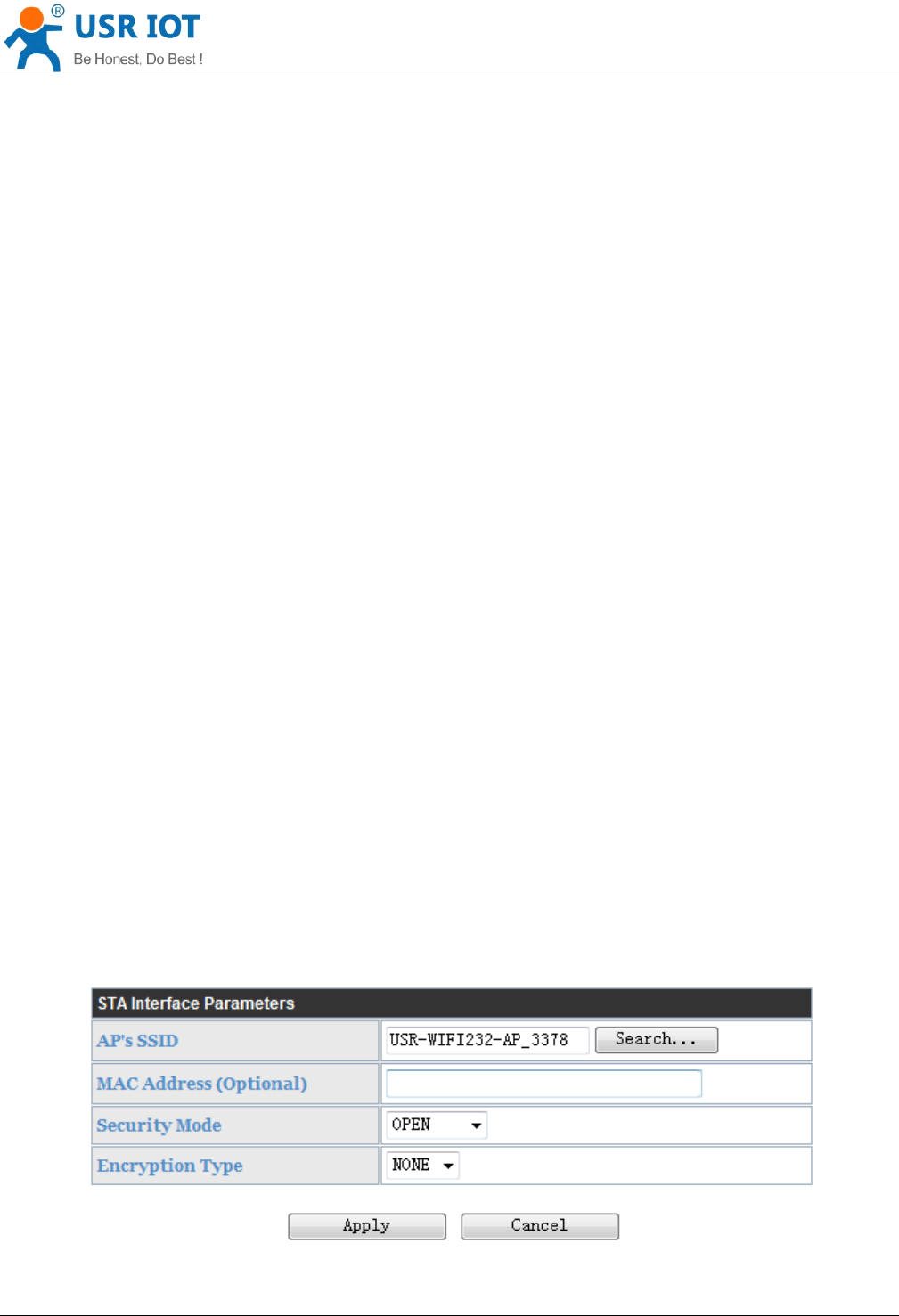
This page use to setting the parameters when Convert Server works as STA.
Convert Server User Manual www.usr iot
.
c o
m
Jinan USR IOT Technology Limited 29
/
42 tec@usr.cn
Such as SSID of AP which Convert Server need to connected, and also select the networking type: DHCP or
static IP address.
Figure
Figure
Figure
Figure 14
14
14
14
STA
STA
STA
STA
Interface
Interface
Interface
Interface Setting
Setting
Setting
Setting Page
Page
Page
Page
6.1.6.
6.1.6.
6.1.6.
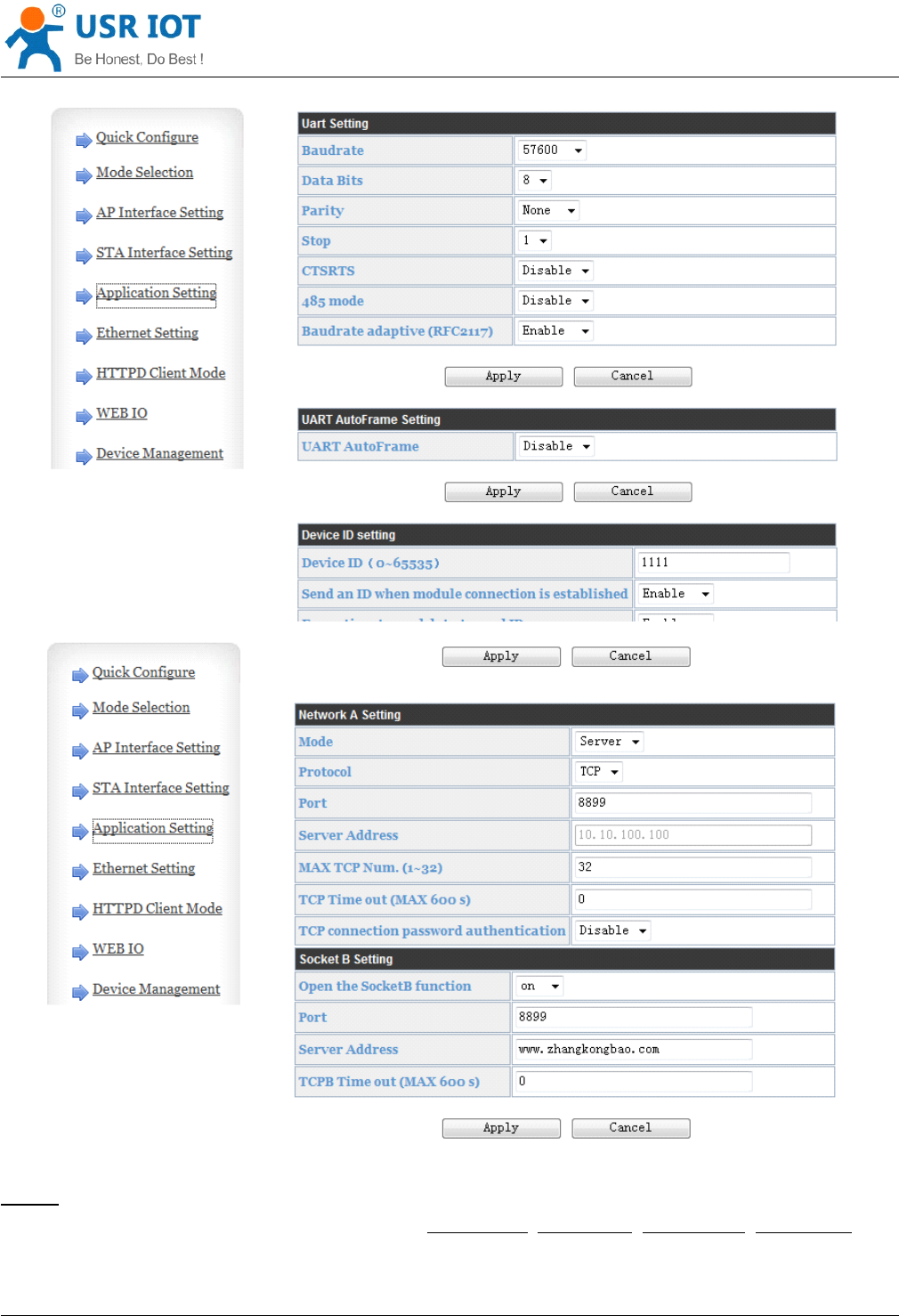
6.1.6. Application
Application
Application
Application Setting
Setting
Setting
Setting Page
Page
Page
Page
This page use to setting the parameters of serial port communication, such as UART setting , UART
AutoFrame Setting , Ethernet function ,Device ID setting and high layer network protocol setting which used
support serial communication.
Convert Server User Manual www.usr iot
.
c o
m
Jinan USR IOT Technology Limited 30
/
42 tec@usr.cn
Figure
Figure
Figure
Figure 15
15
15
15 Application
Application
Application
Application Setting
Setting
Setting
Setting Page
Page
Page
Page
Notes:
Notes:
Notes:
Notes:
Generally, Network protocols support three modes: TCP
TCP
TCP
TCP Server
Server
Server
Server ,TCP
TCP
TCP
TCP Client
Client
Client
Client ,UDP
UDP
UDP
UDP Server
Server
Server
Server ,UDP
UDP
UDP
UDP Client
Client
Client
Client .
When the Convert Server is configured to UDP server side, the Convert Server will memory the UDP client
end of the last communication, and communication with this UDP client.While the UDP client mode will only
Convert Server User Manual www.usr iot
.
c o
m
Jinan USR IOT Technology Limited 31
/
42 tec@usr.cn
with the target
IP
address and communication.When set to the TCP Server, do not need to enter the IP
address.For other Settings, need to fill in the need to connect each other
IP
address.Fill in port with protocol
port number, at the ends of the communication port number must be the same.
The Socket B only as a TCP client terminal to communicate with the server.
TCP connection password authentication: when the Convert Server in the TCP server mode, password
authentication on the TCP client connect to.
Note: this verification is only in a Convert Server as a TCP server.After the opening, the TCP client connected
Convert Server , the first data which sent to the Convert Server is password and carriage returns.The
password is the password to login page default is "admin".Such as the default when sending the first data
should be "0x61 0x64 0x6D 0x69 0x6E 0x0D 0x0A" (hex) .
6.1.7.
6.1.7.
6.1.7.
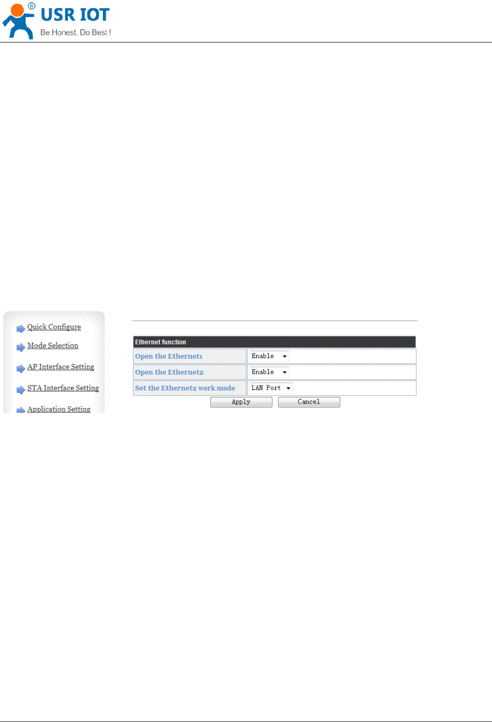
6.1.7. Ethernet
Ethernet
Ethernet
Ethernet Setting
Setting
Setting
Setting
This page is used to set two Ethernet front-end ports of the Convert Server , two Ethernet front-end ports
can be open or closed.And so the second can be set to the WAN port to use, this Convert Server can be used
as a secondary router, making it easy for users to network.Specific Settings page is as follows:
Figure
Figure
Figure
Figure 16
16
16
16 Ethernet
Ethernet
Ethernet
Ethernet Setting
Setting
Setting
Setting Page
Page
Page
Page
6.1.8.
6.1.8.
6.1.8.
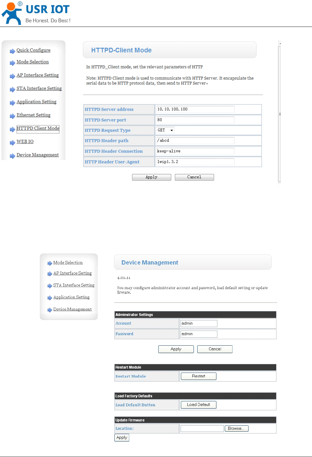
6.1.8. HTTPD
HTTPD
HTTPD
HTTPD Client
Client
Client
Client Mode
Mode
Mode
Mode
This page sets the HTTP header in the HTTPD Client mode.Include: the address of the server, the server port,
request type, protocol header path, Connection, user-agent.
HTTPD Client mode support POST, PUT, GET three HTTP request types.Is a POST or PUT request way,
serial data can be added to the back of the HTTP header;When the request is a GET, data can be added to
the back of the path in the HTTP header.The specific way of sending data can consult section 4.2.4.
Convert Server User Manual www.usr iot
.
c o
m
Jinan USR IOT Technology Limited 32
/
42 tec@usr.cn
Figure
Figure
Figure
Figure 17
17
17
17 HTTPD
HTTPD
HTTPD
HTTPD Client
Client
Client
Client Mode
Mode
Mode
Mode Page
Page
Page
Page
6.1.9.
6.1.9.
6.1.9.
6.1.9. Device
Device
Device
Device Management
Management
Management
Management Page
Page
Page
Page
This page use to manage Convert Server general setting, such as administrator setting, restart Convert
Server button, restore factory default setting button, and update firmware through webpage.

Convert Server User Manual www.usr iot
.
c o
m
Jinan USR IOT Technology Limited 33
/
42 tec@usr.cn
Figure
Figure
Figure
Figure 18
18
18
18 Device
Device
Device
Device Management
Management
Management
Management Page
Page
Page
Page
Notes:
Notes:
Notes:
Notes:
Restart module button: When you setting the parameters of different web pages, you will click “ Apply ” button
to confirm the setting, but the setting take effect only after user click the “ Restart ” button here, the Convert
Server will re-boot up and ref re sh the memory information with new changes.
Convert Server User Manual www.usr iot
.
c o
m
Jinan USR IOT Technology Limited 34
/
42 tec@usr.cn
Appendix
Appendix
Appendix
Appendix A
A
A
A :
:
:
: Questions
Questions
Questions
Questions and
and
and
and Answers
Answers
Answers
Answers
Q1:
Q1:
Q1:
Q1: How
How
How
How to
to
to
to configure
configure
configure
configure transparent
transparent
transparent
transparent serial
serial
serial
serial port
port
port
port application
application
application
application (TCP
(TCP
(TCP
(TCP protocol)
protocol)
protocol)
protocol) with
with
with
with
two
two
two
two Convert
Convert
Convert
Convert Server
Server
Server
Server s?
s?
s?
s?
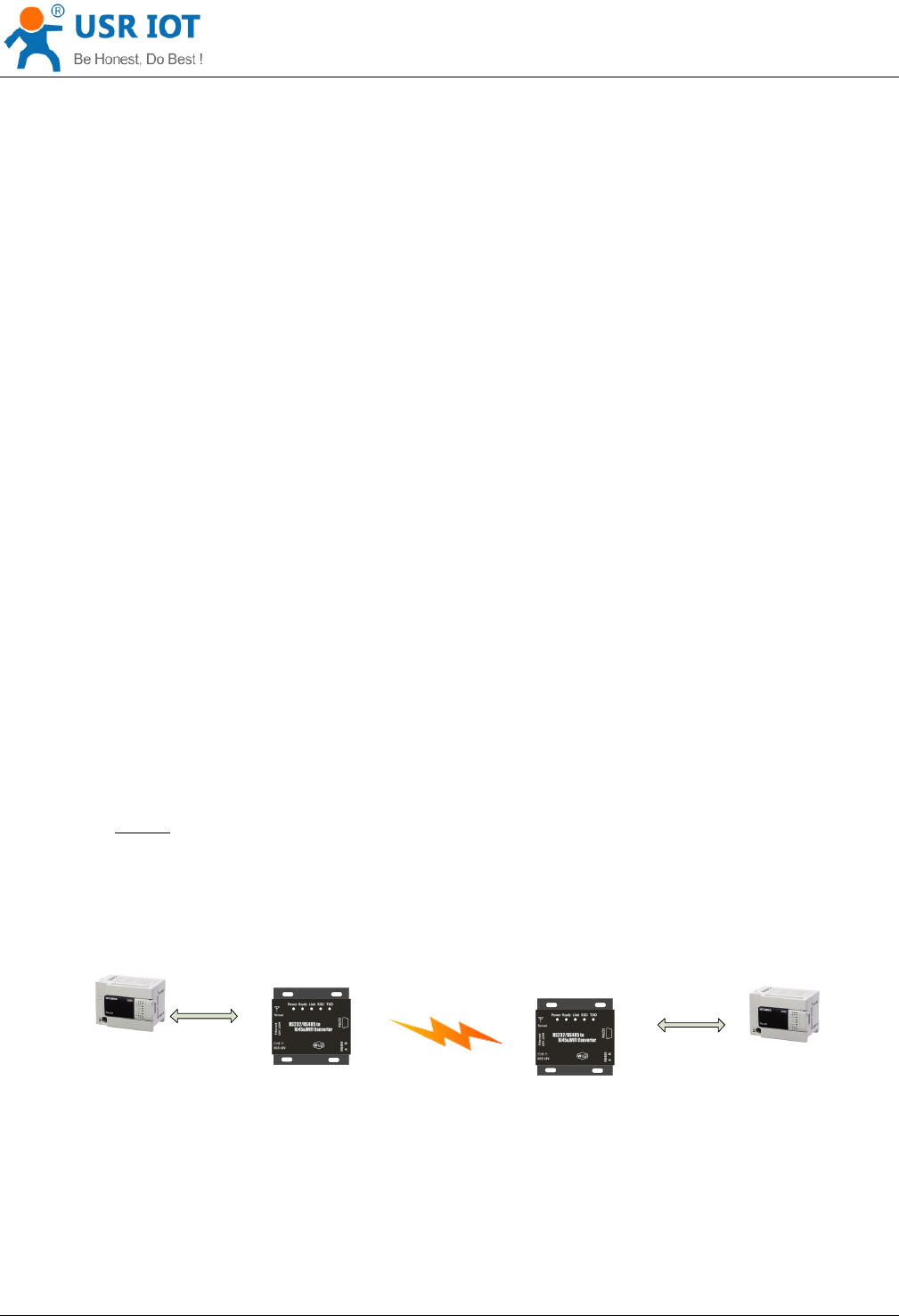
Network structure as below figure:
Convert Server 1# Setting:
Works as AP mode;
--See “ Mode Selection Page
”
LAN IP address: 10.10.100.254;
--See “ AP Interface Setting Page
”
Network Protocal:TCP/Server, Port ID: 8899;
-- See “ Application Setting Page
”
( Convert Server default setting);
Convert Server 2# Setting:
Works as
STA
mode; --See “ Mode Selection Page ”
WAN connection type: DHCP or Static IP (For this example:10.10.100.100)
--See “ STA
Interface Setting Page
”
Network Protocal:TCP/Client, Port ID: 8899; Application IP address: Convert Server 1#
’
s LAN IP
address (10.10.100.254);
-- See “ Application Setting Page
”
Notes:
Notes:
Notes:
Notes: When Convert Server 2# works as STA mode, Convert Server
’
s WiFi interface works as
WAN port. Convert Server ’ s WAN IP address and LAN IP address shall be setting different segment.
So, Convert Server 2# ’ s LAN IP address must change to other segment; (For this sample, we
change to 10.10.99.254);
--See “ AP Interface Setting Page
”
USR
-
WIFI
232
-
602
/
604
/
610
/ 2
User
Device
UART
USR
-
WIFI
232
-
602
/
604
/
610
/ 2
UART
AP SSID
:
USR
-
WIFI
232
-
AP
_
xxxx
LAN IP
:
10
.
10
.
100
.
254
Net Prot
:
Tcp Server
Protocol Port
:
8899
STA SSID
:
USR
-
WIFI
232
-
AP
_
xxxx
WAN IP
:
DHCP
Net Prot
:
Tcp client
10
.
10
.
100
.
254
:
8899
LAN IP
:
10
.
10
.
99
.
254
1 #
2 #
User
Device
Figure
Figure
Figure
Figure 19
19
19
19 Configure
Configure
Configure
Configure Transparent
Transparent
Transparent
Transparent Serial
Serial
Serial
Serial Port
Port
Port
Port Connection
Connection
Connection
Connection (TCP)
(TCP)
(TCP)
(TCP)
Convert Server User Manual www.usr iot
.
c o
m
Jinan USR IOT Technology Limited 35
/
42 tec@usr.cn
Q2:
Q2:
Q2:
Q2: Where
Where
Where
Where to
to
to
to Set
Set
Set
Set WIFI
WIFI
WIFI
WIFI Convert
Convert
Convert
Convert Server
Server
Server
Server LAN
LAN
LAN
LAN IP
IP
IP
IP and
and
and
and WAN
WAN
WAN
WAN IP
IP
IP
IP through
through
through
through Web
Web
Web
Web
Page
Page
Page
Page ?
?
?
?
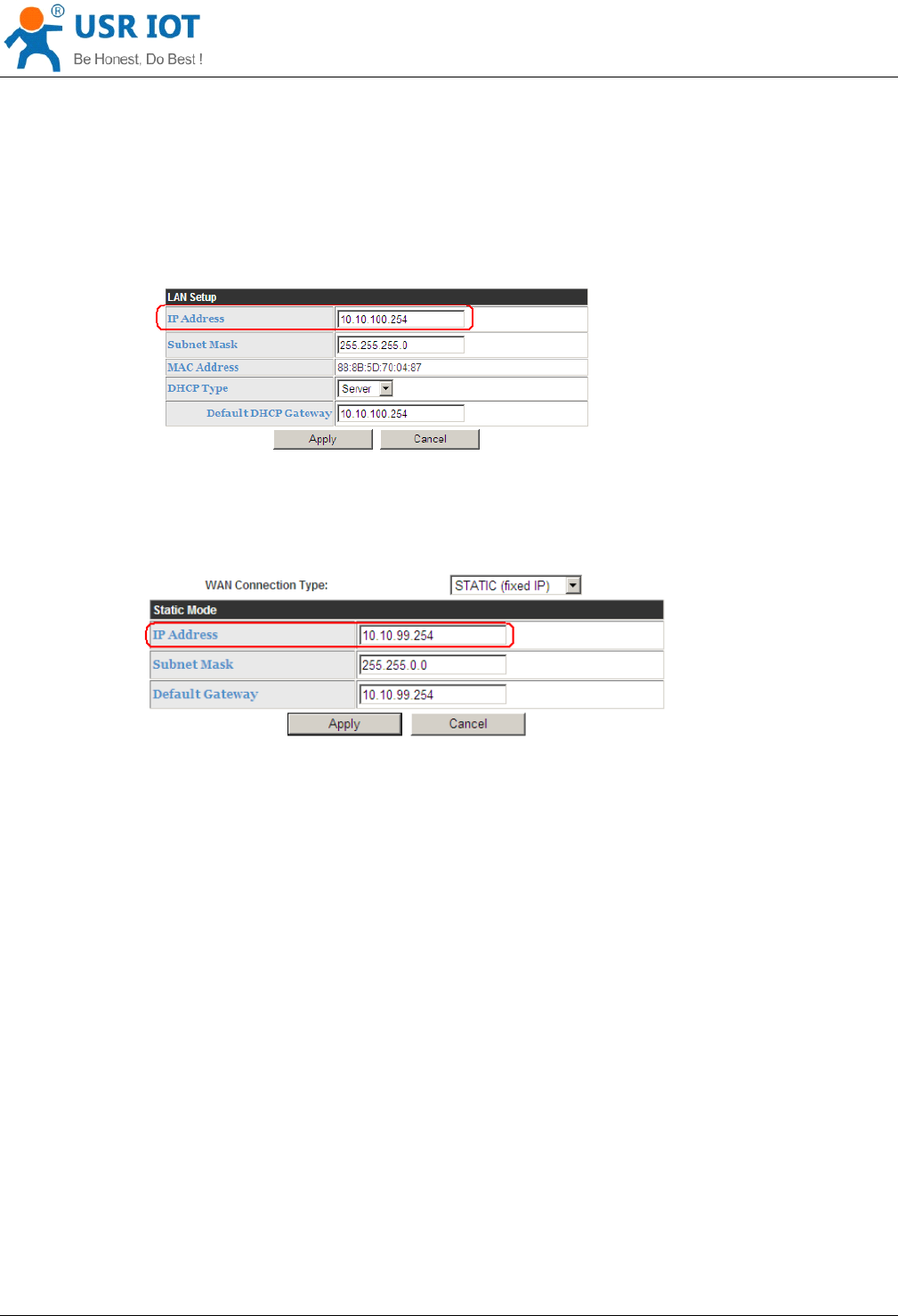
USR-WIFI232-D2 Wireless LAN IP address setting see “ AP Interface Setting Page ” as below Figure,
Figure
Figure
Figure
Figure 20
20
20
20 Convert
Convert
Convert
Convert Server
Server
Server
Server LAN
LAN
LAN
LAN IP
IP
IP
IP Setting
Setting
Setting
Setting
USR-WIFI232-D2 Wireless WAN IP address setting see “ STA Interface Setting Page ” as below Figure, User
can set WAN connection type to DHCP and
STATIC
IP.
Figure
Figure
Figure
Figure 21
21
21
21 Convert
Convert
Convert
Convert Server
Server
Server
Server WAN
WAN
WAN
WAN IP
IP
IP
IP Setting
Setting
Setting
Setting
Q3:
Q3:
Q3:
Q3: How
How
How
How to
to
to
to configure
configure
configure
configure transparent
transparent
transparent
transparent serial
serial
serial
serial port
port
port
port application
application
application
application (UDP
(UDP
(UDP
(UDP protocol)
protocol)
protocol)
protocol) with
with
with
with
two
two
two
two Convert
Convert
Convert
Convert Server
Server
Server
Server s?
s?
s?
s?
Network structure as below figure:
Convert Server 1# Setting:
Works as AP mode;
--See “ Mode Selection Page
”
LAN IP address: 10.10.100.254;
--See “ AP Interface Setting Page
”
Network Protocal:UDP, Port ID: 8899; Application IP address:10.10.100.100;
-- See “ Application Setting Page
”
Convert Server 2# Setting:
Works as
STA
mode; --See “ Mode Selection Page ”
WAN connection type: Static IP (10.10.100.100)
--See “ STA
Convert Server User Manual www.usr iot
.
c o
m
Jinan USR IOT Technology Limited 36
/
42 tec@usr.cn
Interface Setting Page
”
Network Protocal:UDP, Port ID: 8899; Application IP address: Convert Server 1#
’
s LAN IP address
(10.10.100.254);
-- See “ Application Setting Page
”
LAN IP address: 10.10.99.254 (Different net segment with WAN port)
--See “ AP Interface Setting Page
”
USR
-
WIFI
232
-
602
/
604
/
610
/ 2
User
Device
UART
USR
-
WIFI
232
-
602
/
604
/
610
/ 2
UART
AP SSID
:
USR
-
WIFI
232
-
AP
_
xxxx
LAN IP
:
10
.
10
.
100
.
254
Net Prot
:
UDP
10
.
10
.
100
.
100
:
8899
STA SSID
:
USR
-
WIFI
232
-
AP
_
xxxx
WAN IP
:
DHCP
Net Prot
:
UDP
10
.
10
.
100
.
254
:
8899
LAN IP
:
10
.
10
.
99
.
254
1 #
2 #
User
Device
Figure
Figure
Figure
Figure 22
22
22
22 Configure
Configure
Configure
Configure Transparent
Transparent
Transparent
Transparent Serial
Serial
Serial
Serial Port
Port
Port
Port Connection
Connection
Connection
Connection (UDP)
(UDP)
(UDP)
(UDP)
Q4:
Q4:
Q4:
Q4: Where
Where
Where
Where to
to
to
to set
set
set
set Convert
Convert
Convert
Convert Server
Server
Server
Server network
network
network
network protocol
protocol
protocol
protocol (TCP/UDP)?
(TCP/UDP)?
(TCP/UDP)?
(TCP/UDP)?
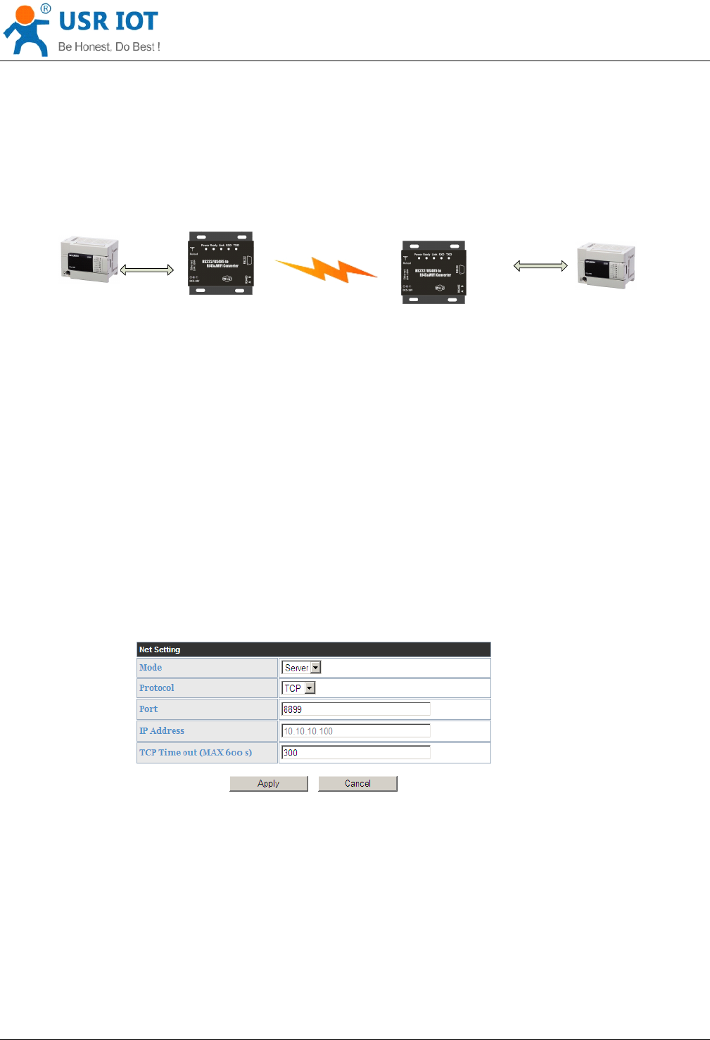
USR-WIFI232-D2 network protocol setting see “ Application Setting Page ” as below Figure,
Protocol: TCP Server
Only Port ID required: 8899 (Default)
Figure
Figure
Figure
Figure 23
23
23
23 Convert
Convert
Convert
Convert Server
Server
Server
Server Network
Network
Network
Network Protocols:
Protocols:
Protocols:
Protocols: TCP/Server
TCP/Server
TCP/Server
TCP/Server
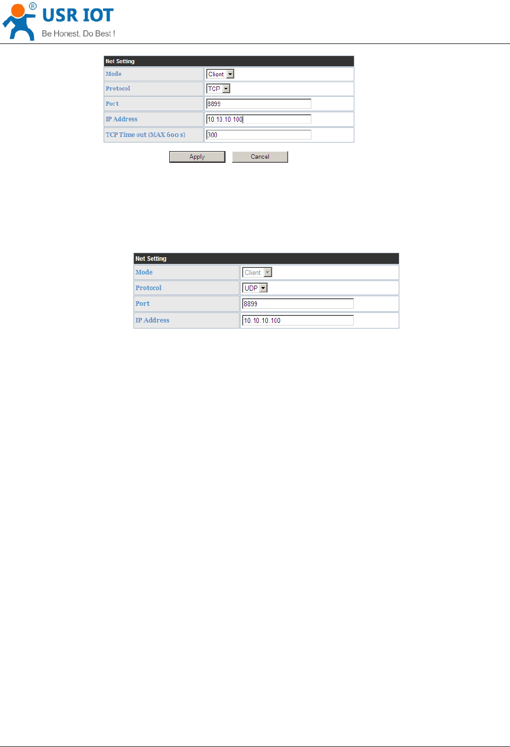
Protocol: TCP Client
Application IP address required: it ’ s target TCP server ‘ s
IP
address;
Port ID required: 8899 (Default)
Convert Server User Manual www.usr iot
.
c o
m
Jinan USR IOT Technology Limited 37
/
42 tec@usr.cn
Figure
Figure
Figure
Figure 24
24
24
24 Convert
Convert
Convert
Convert Server
Server
Server
Server Network
Network
Network
Network Protocol:
Protocol:
Protocol:
Protocol: TCP/Client
TCP/Client
TCP/Client
TCP/Client
Protocol: UDP
No Server/Client selection required;
Application IP address required: it ’ s target device ‘ s IP address;
Port ID required: 8899 (Default)
Figure
Figure
Figure
Figure 25
25
25
25 Convert
Convert
Convert
Convert Server
Server
Server
Server Network
Network
Network
Network Protocol:
Protocol:
Protocol:
Protocol: UDP
UDP
UDP
UDP
Q5:
Q5:
Q5:
Q5: How
How
How
How to
to
to
to configure
configure
configure
configure transparent
transparent
transparent
transparent serial
serial
serial
serial port
port
port
port application:
application:
application:
application: Two
Two
Two
Two Convert
Convert
Convert
Convert
Server
Server
Server
Server s
s
s
s all
all
all
all configured
configured
configured
configured as
as
as
as
STA
STA
STA
STA
and
and
and
and connection
connection
connection
connection through
through
through
through AP?
AP?
AP?
AP?
Network structure as below figure:
Convert Server 1# Setting: ( We use USR-WIFI232-D2 as AP for this example)
Works as AP mode and all default setting;
Convert Server 2# Setting:
Works as
STA
mode; --See “ Mode Selection Page ”
WAN connection type: Static IP: 10.10.100.100;
--See “ STA Interface Setting Page
”
Network Protocal:TCP/Server, Port ID: 8899;
-- See “ Application Setting Page
”
LAN IP address: 10.10.99.254 (Different net segment with WAN port);
--See “ AP Interface Setting Page
”
Convert Server 3# Setting:
Works as
STA
mode; --See “ Mode Selection Page ”
WAN connection type: Static IP: 10.10.100.101;
--See “ STA Interface Setting Page
”
Network Protocal:TCP/Client, Port ID: 8899; Application IP address: Convert Server 2#
’
s WAN IP
address (10.10.100.100);
-- See “ Application Setting Page
”
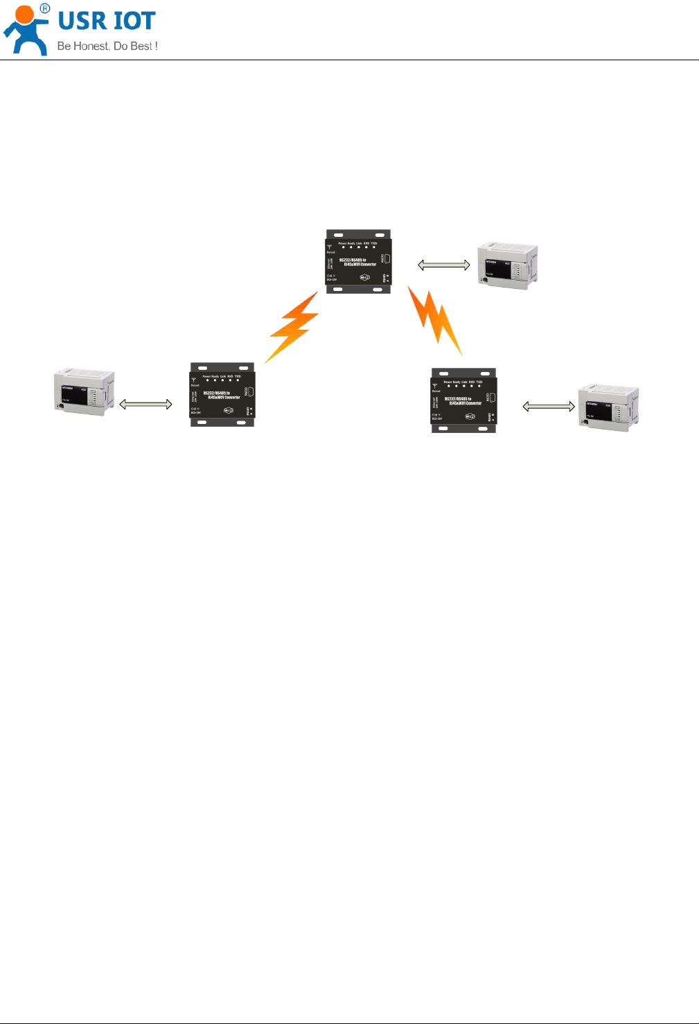
Convert Server User Manual www.usr iot
.
c o
m
Jinan USR IOT Technology Limited 38
/
42 tec@usr.cn
LAN IP address: 10.10.98.254 (Different net segment with WAN port);
--See “ AP Interface Setting Page
”
User
Device
UART
USR
-
WIFI
232
-
602
/
604
/
610
/ 2
UART
UART
STA SSID
:
USR
-
WIFI
232
-
AP
_
xxxx
LAN IP
:
10
.
10
.
99
.
254
WAN IP
:
10
.
10
.
100
.
100
Net Prot
:
Tcp Server
Protocol Port
:
8899
STA SSID
:
USR
-
WIFI
232
-
AP
_
xxxx
WAN IP
:
10
.
10
.
100
.
101
Net Prot
:
Tcp client
10
.
10
.
100
.
100
:
8899
LAN IP
:
10
.
10
.
98
.
254
AP SSID
:
USR
-
WIFI
232
-
AP
_
xxxx
LAN IP
:
10
.
10
.
100
.
254
Net Prot
:
Tcp Server
Protocol Port
:
8899
User
Device
User
Device
USR
-
WIFI
232
-
602
/
604
/
610
/ 2
USR
-
WIFI
232
-
602
/
604
/
610
/ 2
Figure
Figure
Figure
Figure 26
26
26
26 Two
Two
Two
Two Convert
Convert
Convert
Convert Server
Server
Server
Server s
s
s
s Connection
Connection
Connection
Connection Through
Through
Through
Through AP
AP
AP
AP
Q6:
Q6:
Q6:
Q6: How
How
How
How to
to
to
to avoid
avoid
avoid
avoid IP
IP
IP
IP address
address
address
address confliction
confliction
confliction
confliction when
when
when
when apply
apply
apply
apply Convert
Convert
Convert
Convert Server
Server
Server
Server ?
?
?
?
The following address allocation method can avoid the IP address confliction for dynamic and static IP
address mixed application.
Convert Server dynamic IP address range from 100 to 200 for last IP address segment.
Such as default IP: 10.10.100.254. When Convert Server works as
AP,
the IP address Convert
Server can allocate to STA is from 10.10.100.100 to 10.10.100.200;
So, if user needs to set static IP for dedicated
STA
internal network, the available IP address range
can start from 10.10.100.1 to 10.10.100.99.
Q7:
Q7:
Q7:
Q7: PC
PC
PC
PC works
works
works
works as
as
as
as server,
server,
server,
server, all
all
all
all Convert
Convert
Convert
Convert Server
Server
Server
Server s
s
s
s works
works
works
works as
as
as
as data
data
data
data acquisition
acquisition
acquisition
acquisition card
card
card
card
and
and
and
and connect
connect
connect
connect with
with
with
with PC,
PC,
PC,
PC, how
how
how
how to
to
to
to configure
configure
configure
configure this
this
this
this application?
application?
application?
application?
Network structure as below figure: Three Convert Server setup 3 TCP links with PC server. Convert Server 1#
works as AP and all devices connect to Convert Server 1# through WiFi interface;

Convert Server User Manual www.usr iot
.
c o
m
Jinan USR IOT Technology Limited 39
/
42 tec@usr.cn
PC Setting:
IP address: 10.10.100.100;
Network Protocal:TCP/Server, Port ID: 8899;
Convert Server 1# Setting:
Works as AP mode;
LAN IP address: 10.10.100.254;
Network Protocal:TCP/Client, Port ID: 8899; Application IP address:10.10.100.100;
Convert Server 2# Setting:
Works as
STA
mode;
WAN connection type: Static IP: 10.10.100.101;
Network Protocal:TCP/Client, Port ID: 8899; Application IP address:10.10.100.100;
LAN IP address: 10.10.99.254 (Different net segment with WAN port);
Convert Server 3# Setting:
Works as
STA
mode;
WAN connection type: Static IP: 10.10.100.102;
Network Protocal:TCP/Client, Port ID: 8899; Application IP address:10.10.100.100;
LAN IP address: 10.10.98.254 (Different net segment with WAN port);

Convert Server User Manual www.usr iot
.
c o
m
Jinan USR IOT Technology Limited 40
/
42 tec@usr.cn
USR
-
WIFI
232
-
602
/
604
/
610
/ 2
User
Device
UART
USR
-
WIFI
232
-
602
/
604
/
610
/ 2
User
Device
UART
USR
-
WIFI
232
-
602
/
604
/
610
/ 2
User
Device
UART
IP
:
10
.
10
.
100
.
100
Net Prot
:
tcp
server
,
8899
STA SSID
:
USR
-
WIFI
232
-
AP
_
xxxx
LAN IP
:
10
.
10
.
99
.
254
WAN IP
:
10
.
10
.
100
.
101
Net Prot
:
tcp client
,
10
.
10
.
100
.
100
:
8899
STA SSID
:
USR
-
WIFI
232
-
AP
_
xxxx
LAN IP
:
10
.
10
.
98
.
254
WAN IP
:
10
.
10
.
100
.
102
Net Prot
:
tcp client
,
10
.
10
.
100
.
100
:
8899
AP SSID
:
USR
-
WIFI
232
-
AP
_
xxxx
LAN IP
:
10
.
10
.
100
.
254
Net Prot
:
tcp client
,
10
.
10
.
100
.
100
:
8899
Figure
Figure
Figure
Figure 27
27
27
27 Wireless
Wireless
Wireless
Wireless Data
Data
Data
Data Acquisition
Acquisition
Acquisition
Acquisition Card
Card
Card
Card Setting
Setting
Setting
Setting
Q8:
Q8:
Q8:
Q8: Convert
Convert
Convert
Convert Server
Server
Server
Server support
support
support
support UDP
UDP
UDP
UDP multicast?
multicast?
multicast?
multicast?
At present, all the Convert Server does not support UDP multicast function,IP multicast address range is
" 224.0.0.0 ~ 239.255.255.255 ” , When setting Convert Server , please don't set this IP section, if set, may cause
the Convert Server can't normal start.
Q9:Convert
Q9:Convert
Q9:Convert
Q9:Convert Server
Server
Server
Server operates
operates
operates
operates in
in
in
in STA
STA
STA
STA mode,
mode,
mode,
mode, the
the
the
the PC
PC
PC
PC how
how
how
how to
to
to
to get
get
get
get the
the
the
the IP
IP
IP
IP
Convert
Convert
Convert
Convert Server?
Server?
Server?
Server?
All Convert Server supports UDP search ,they will return to their respective
IP,
MAC, MID, detailed search
process is as follows:
1. PC via UDP broadcast (broadcast address: xx.xx.xx.255, Port: 48899) sent a password, the default
password is: "HF-A11ASSISTHREAD", the password can be used
AT
commands (AT + FASWD) set
up,it's Up to 100 bytes.

Convert Server User Manual www.usr iot
.
c o
m
Jinan USR IOT Technology Limited 41
/
42 tec@usr.cn
2. After the Convert Server receives a password, if the password is correct, to the address (Unicast, Port:
48899) sends local IP address and MAC address and name of the Convert Server .
(IP,
MAC, MID as
10.10.100.254,888 B5D0000E2, guxin).
S o you can get to the IP address of the Convert Server .
Appendix
Appendix
Appendix
Appendix b:
b:
b:
b: The
The
The
The FCC
FCC
FCC
FCC statement
statement
statement
statement
FCC
FCC
FCC
FCC STATEMENT
STATEMENT
STATEMENT
STATEMENT
1. This device complies with Part 15 of the FCC Rules. Operation is subject to the following two
conditions:
(1) This device may not cause harmful interference.
(2) This device must accept any interference received, including interference that may cause
undesired operation.
2. Changes or modifications not expressly approved by the party responsible for compliance could
void the user's authority to operate the equipment.
NOTE: This equipment has been tested and found to comply with the limits for a Class B digital
device, pursuant to Part 15 of the FCC Rules. These limits are designed to provide reasonable
protection against harmful interference in a residential installation.
This equipment generates uses and can radiate radio frequency energy and, if not installed and
used in accordance with the instructions, may cause harmful interference to radio communications.
However, there is no guarantee that interference will not occur in a particular installation. If this
equipment does cause harmful interference to radio or wifi , which can be
determined by turning the equipment off and on, the user is encouraged to try to correct the
interference by one or more of the following measures:
Reorient or relocate the receiving antenna.
Increase the separation between the equipment and receiver.
Connect the equipment into an outlet on a circui t different from that to which the receiver is
connected.
Consult the dealer for help.
FCC
FCC
FCC
FCC Radiation
Radiation
Radiation
Radiation Exposure
Exposure
Exposure
Exposure Statement
Statement
Statement
Statement
This equipment complies with FCC radiation exposure limits set forth for an uncontrolled
environment. This equipment should be installed and operated with minimum distance 20cm
between the radiator & your body .

Convert Server User Manual www.usr iot
.
c o
m
Jinan USR IOT Technology Limited 42
/
42 tec@usr.cn
Appendix
Appendix
Appendix
Appendix c
c
c
c :
:
:
: Contact
Contact
Contact
Contact
Company: Jinan USR IOT Technology Limited
Address: 1-728, Huizhan Guoji Cheng, Gaoxin Qu, Jinan, Shandong, China
Tel:
86-531-55507297, 86-531-88826739
Web: www.usr iot . com
Email: sales@usr.cn, order@usr.cn
Appendix
Appendix
Appendix
Appendix d
d
d
d :
:
:
: Disclaimer
Disclaimer
Disclaimer
Disclaimer
This document provides information about RS232 /RS485 TO RJ45&WIFI CONVERT SERVER , this
document does not grant any license to intellectual property rights. Except the responsibility declared in the
product sale clause, USR does not assume any other responsibilities. In addition, USR does not make any
warranties for the sale and use of this product, including the suitability of the product for a particular purpose,
merchantability or fitness for any patent, copyright or other intellectual property infringement, etc. USR may
make changes to specifications and product descriptions without notice.
Appendix
Appendix
Appendix
Appendix e
e
e
e :
:
:
: Update
Update
Update
Update History
History
History
History
201 4 - 0 1-09 V1.0 created
2014-07-24 V2.0 Increase the HTTPD Client model/serial command mode, modify the GPIO
mode.Increase the TCP password authentication, Keepalive, Websocket, upload ID, adaptive baud rate, etc.