Jinan USR IOT Technology WIFI232D2A Embedded WiFi Module User Manual GPON SFU System Design
Jinan USR IOT Technology Limited Embedded WiFi Module GPON SFU System Design
UserManual.wiki
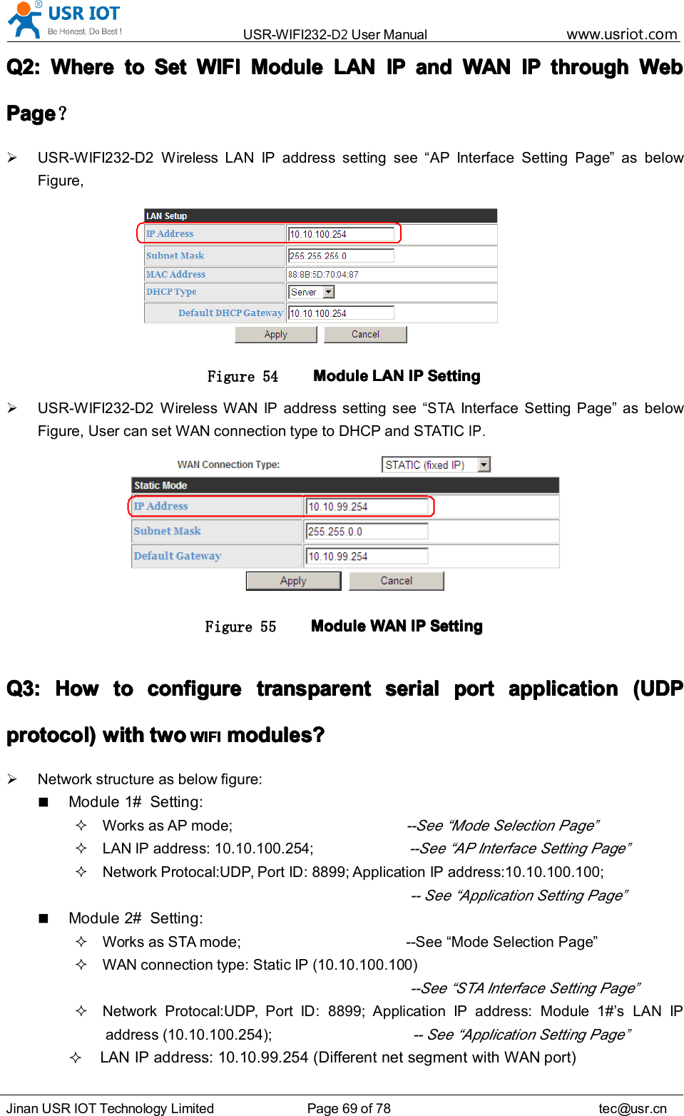
>
Jinan USR IOT Technology
>
WIFI232D2A User Manual
>
Manual
Contents
1.
Manual
2.
Addendum
Manual
Navigation menu
Upload a User Manual
Namespaces
Wiki Guide
HTML
PDF
Info
Views
User Manual
Discussion / Help
Navigation
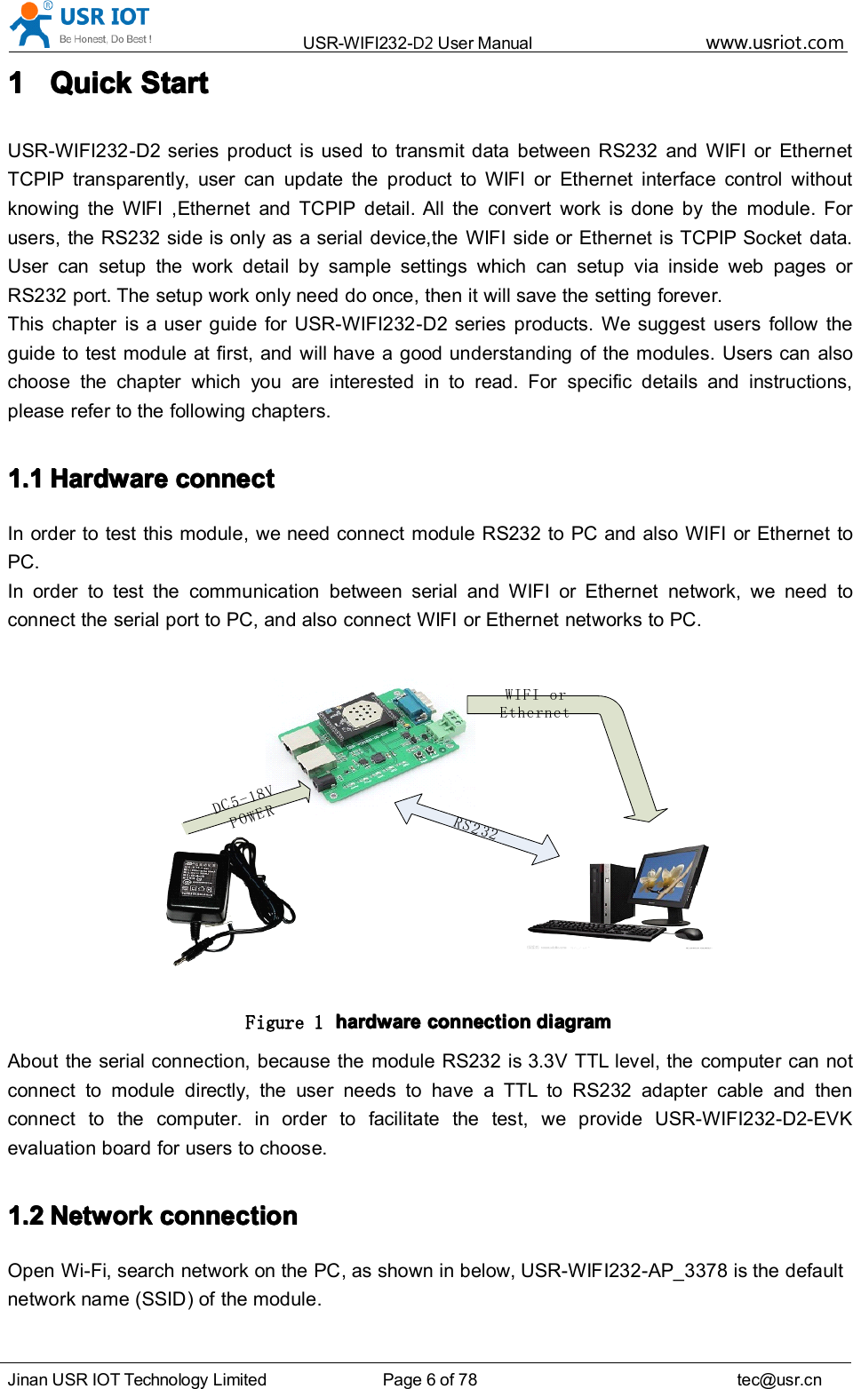
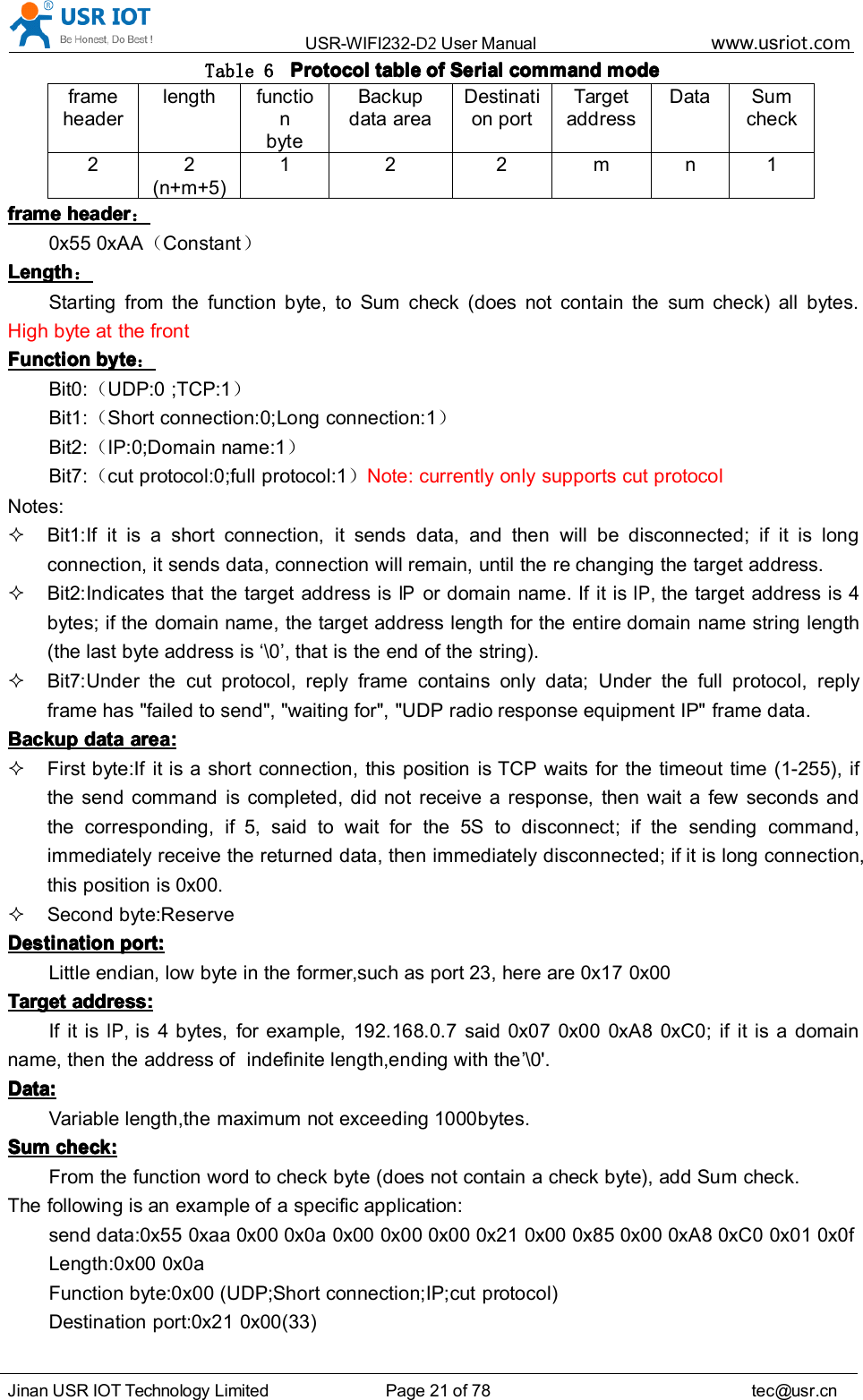
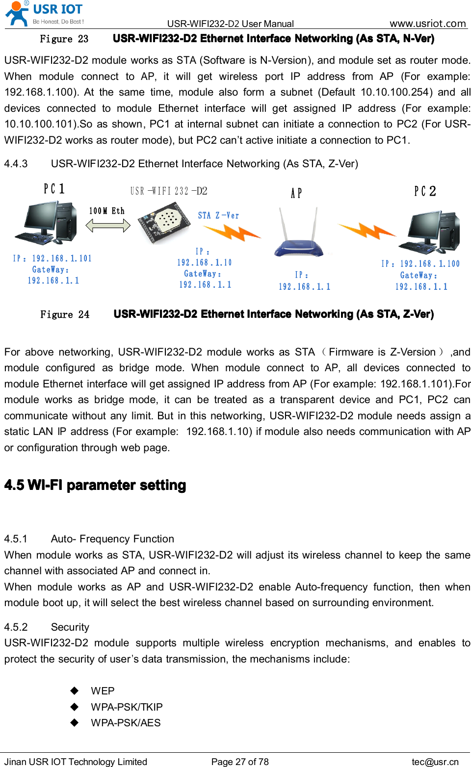
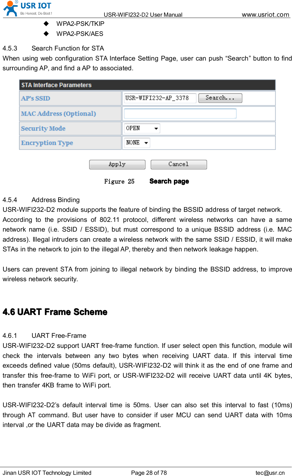
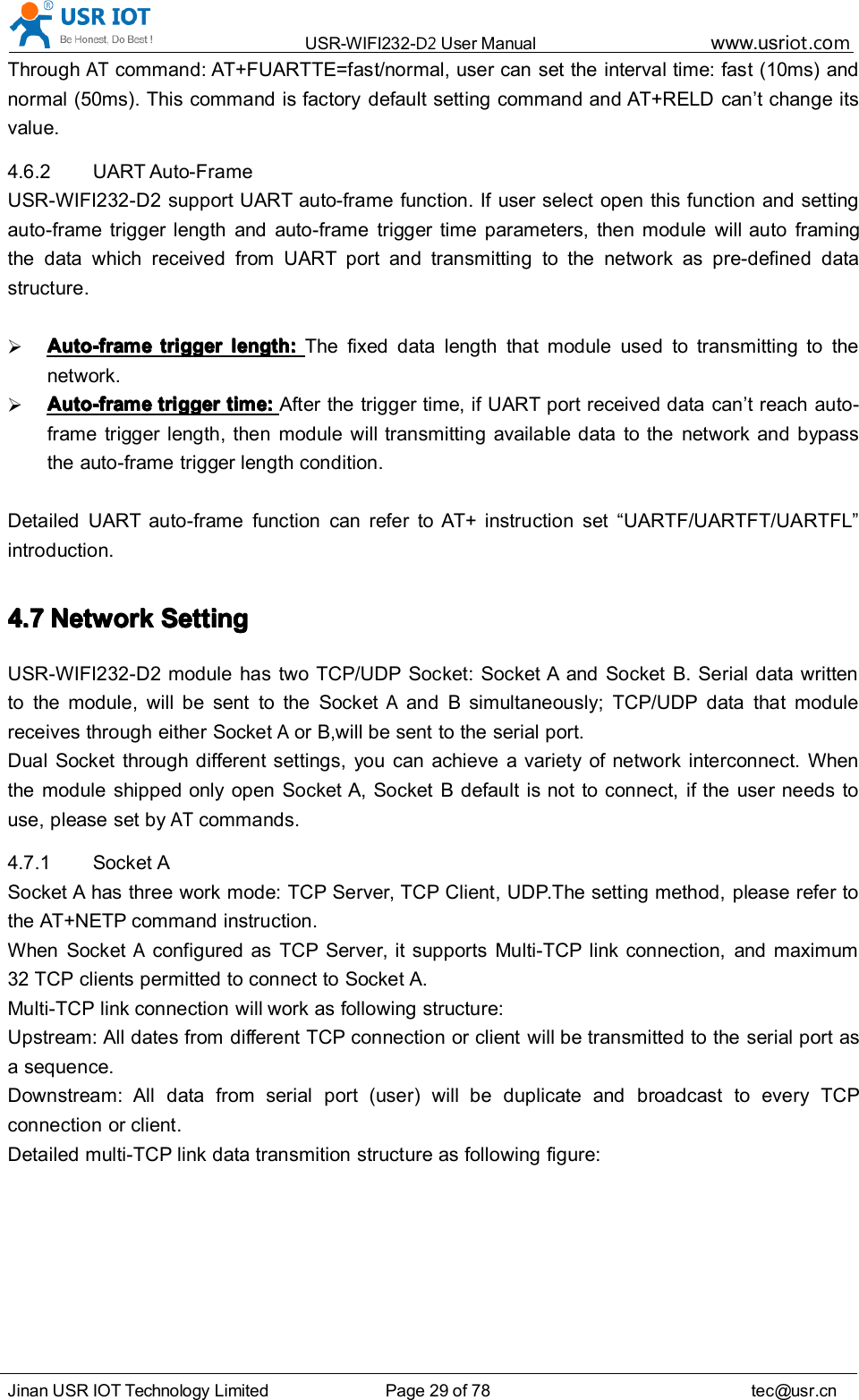
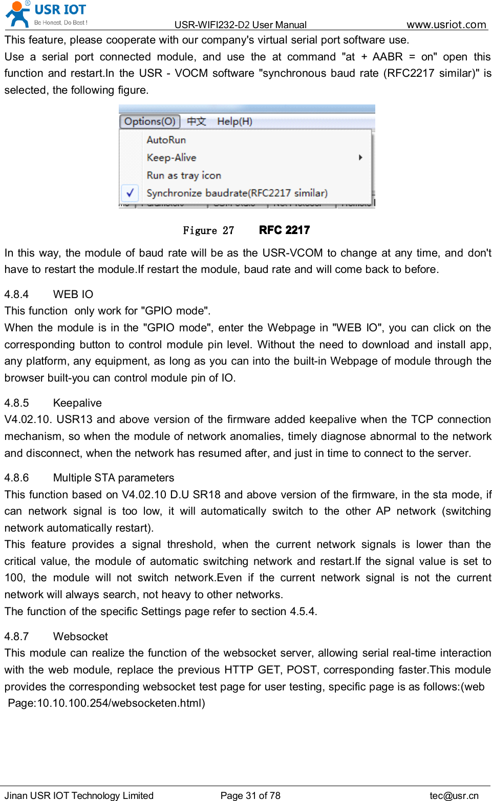
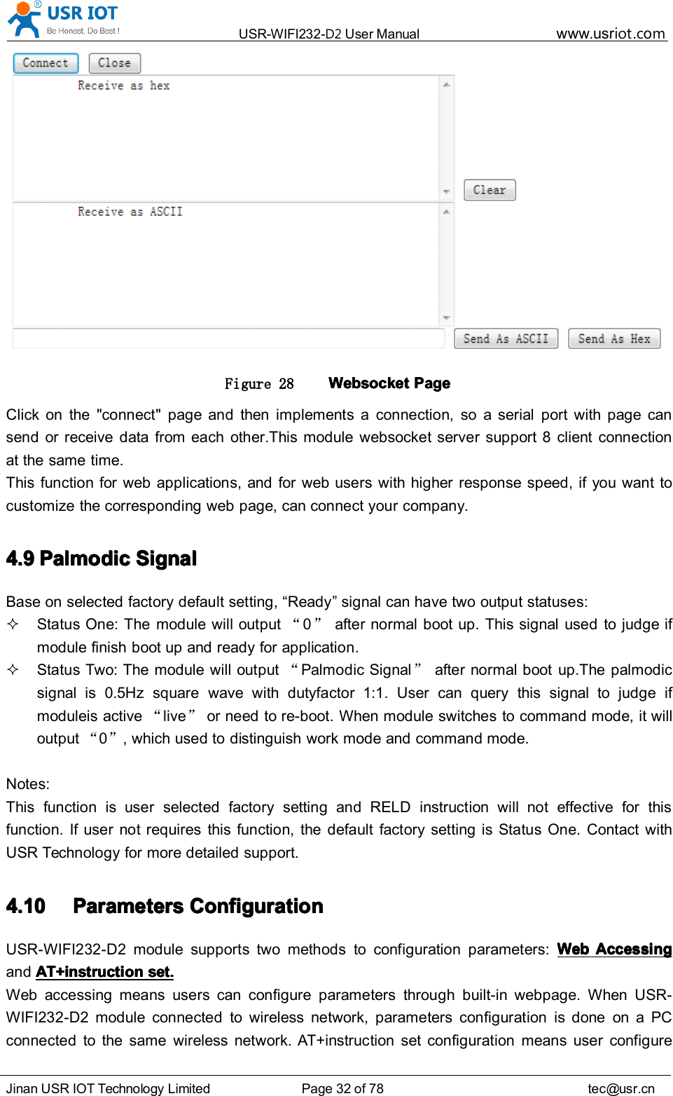
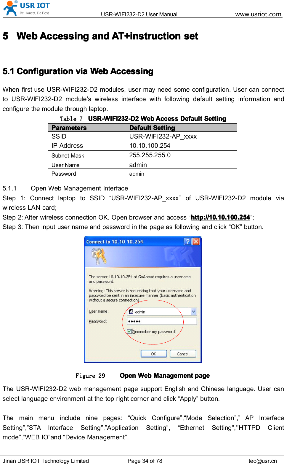
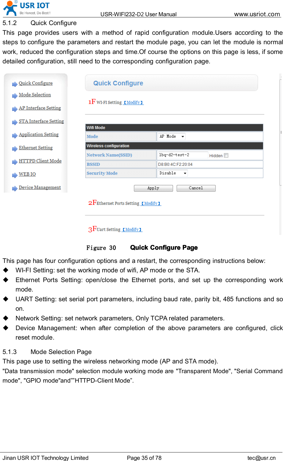
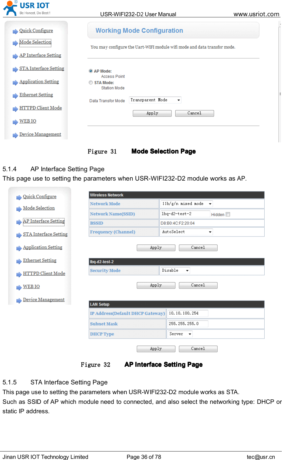
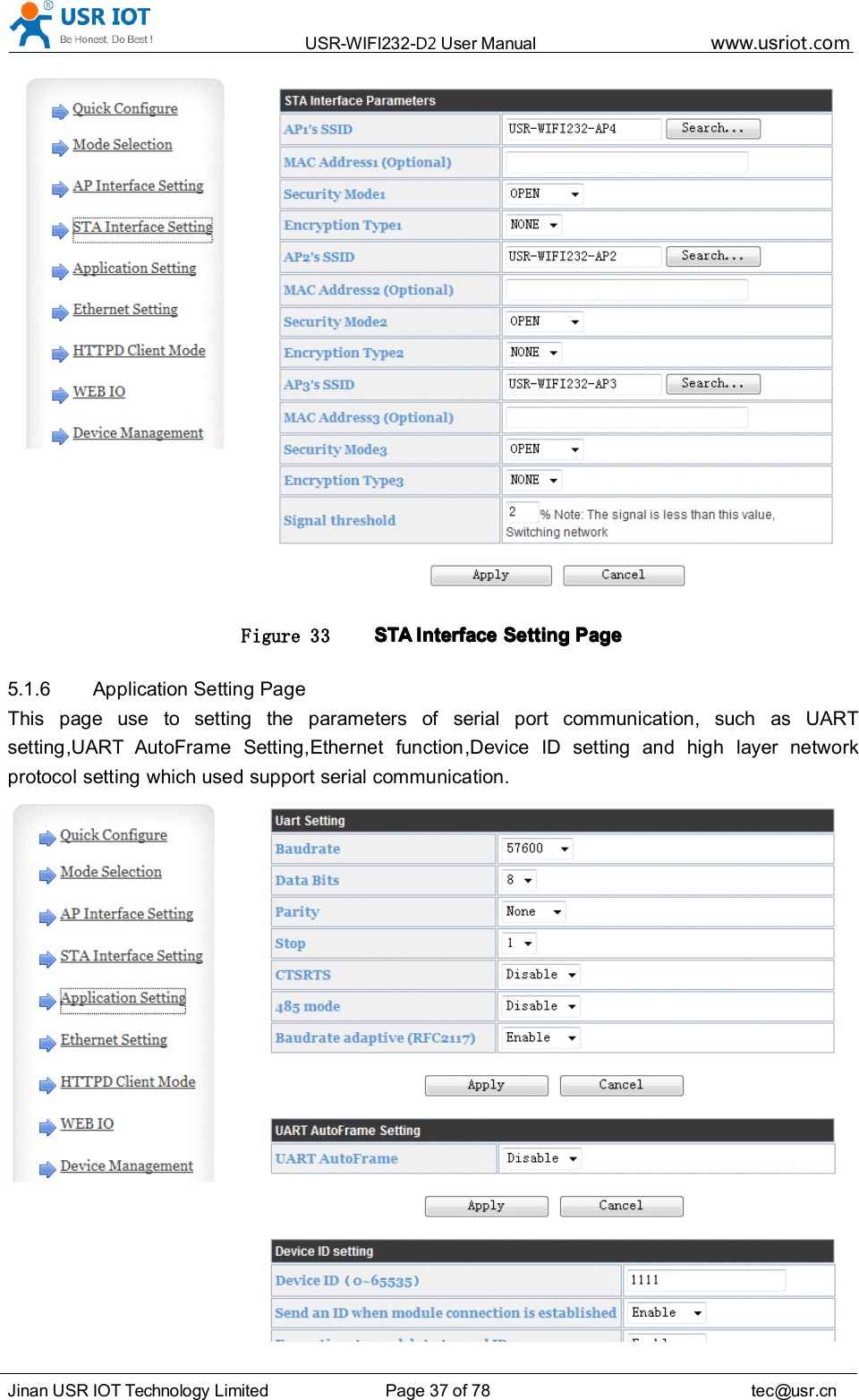
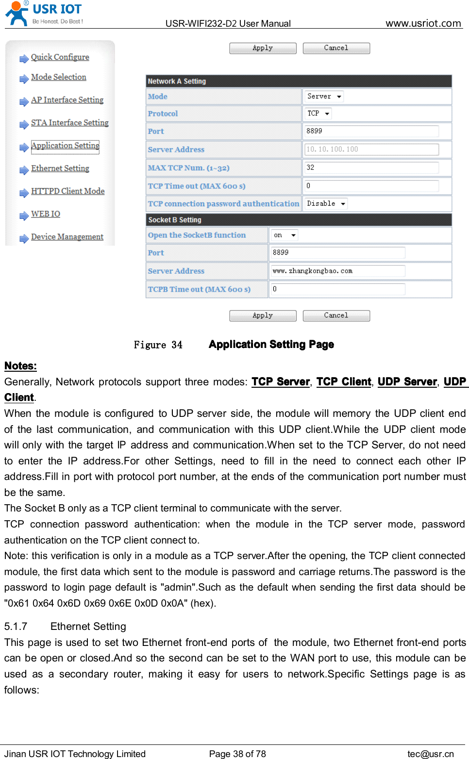
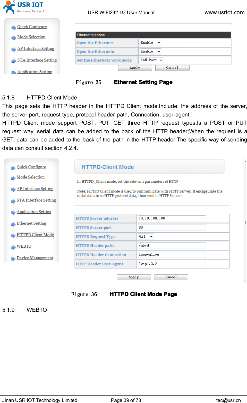
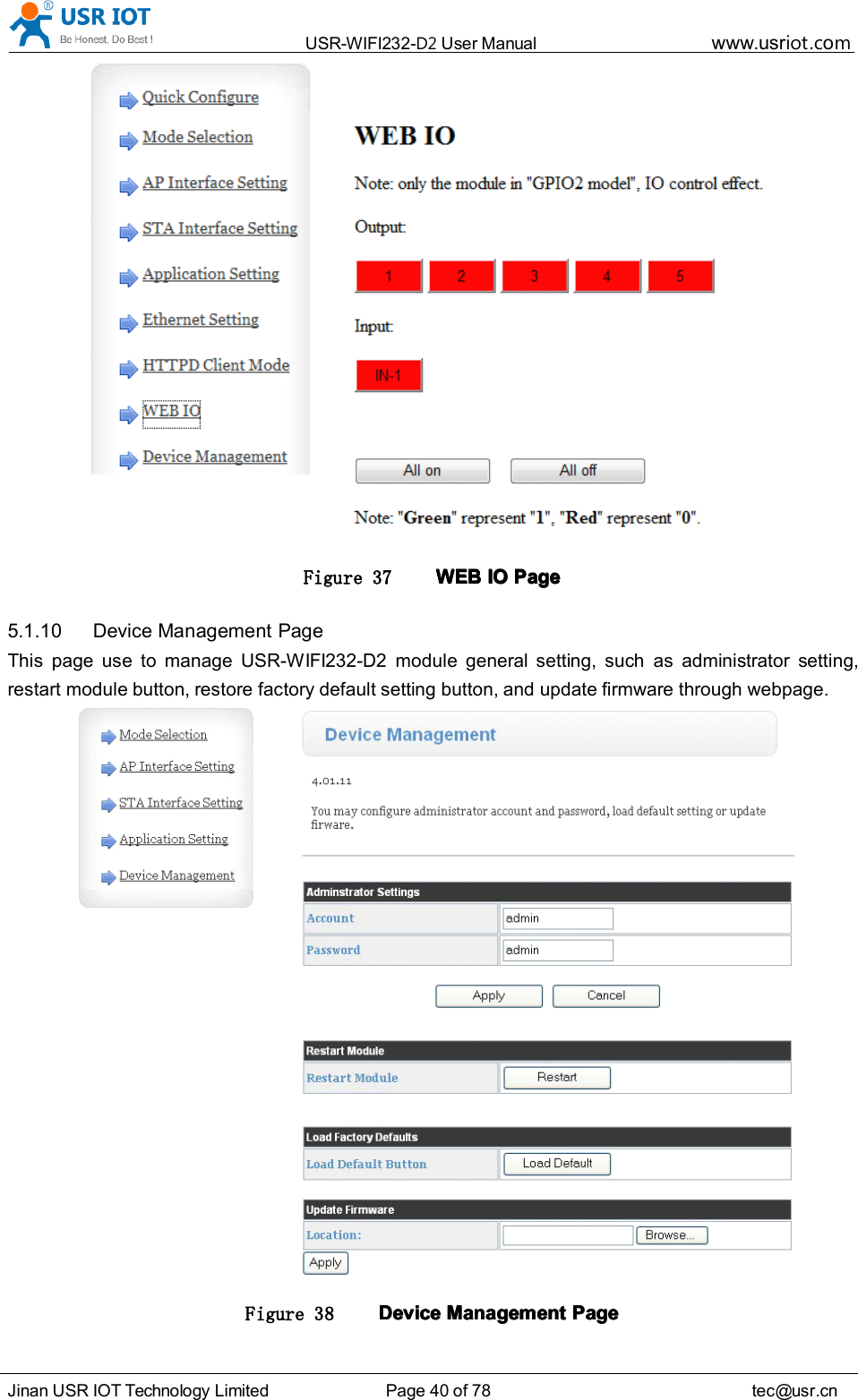
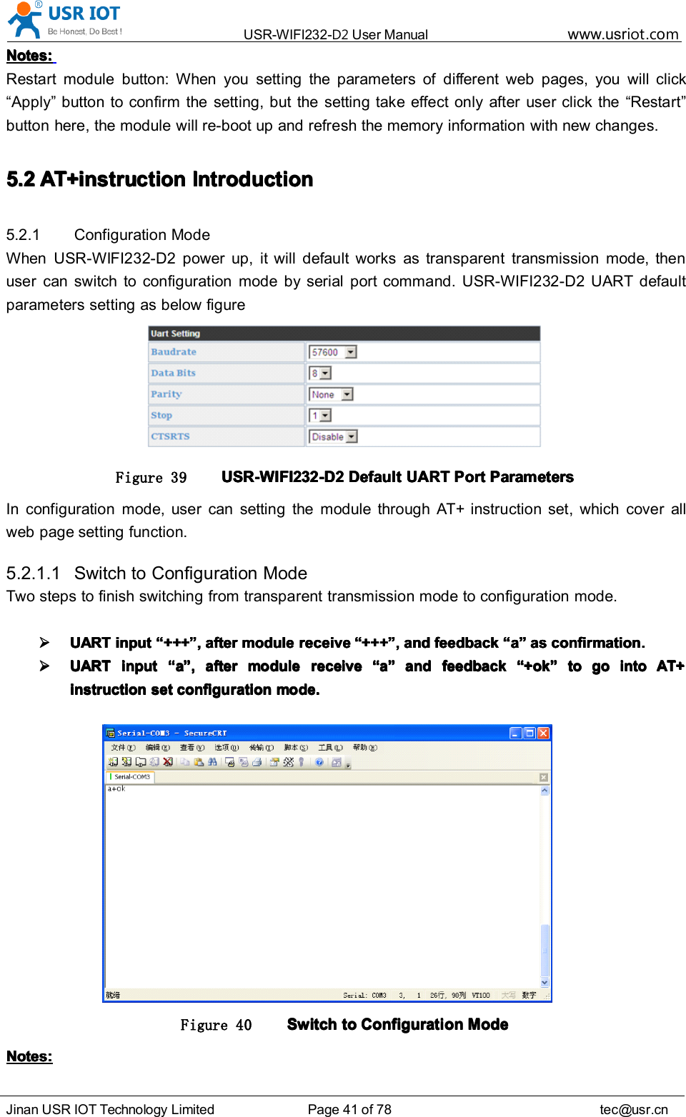
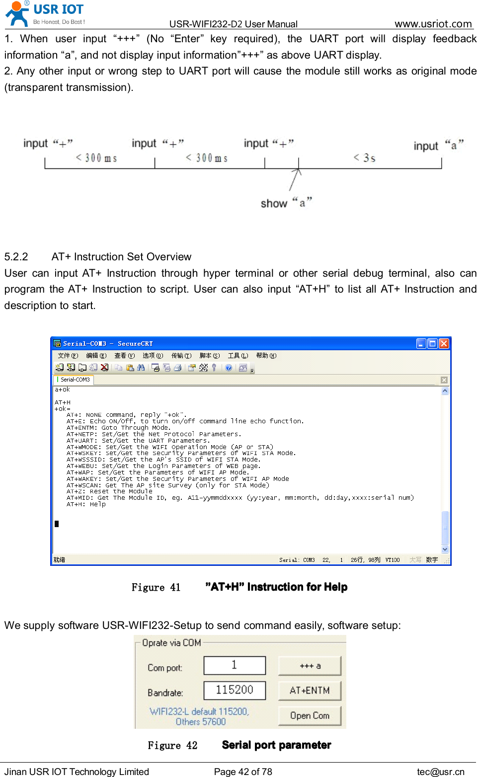
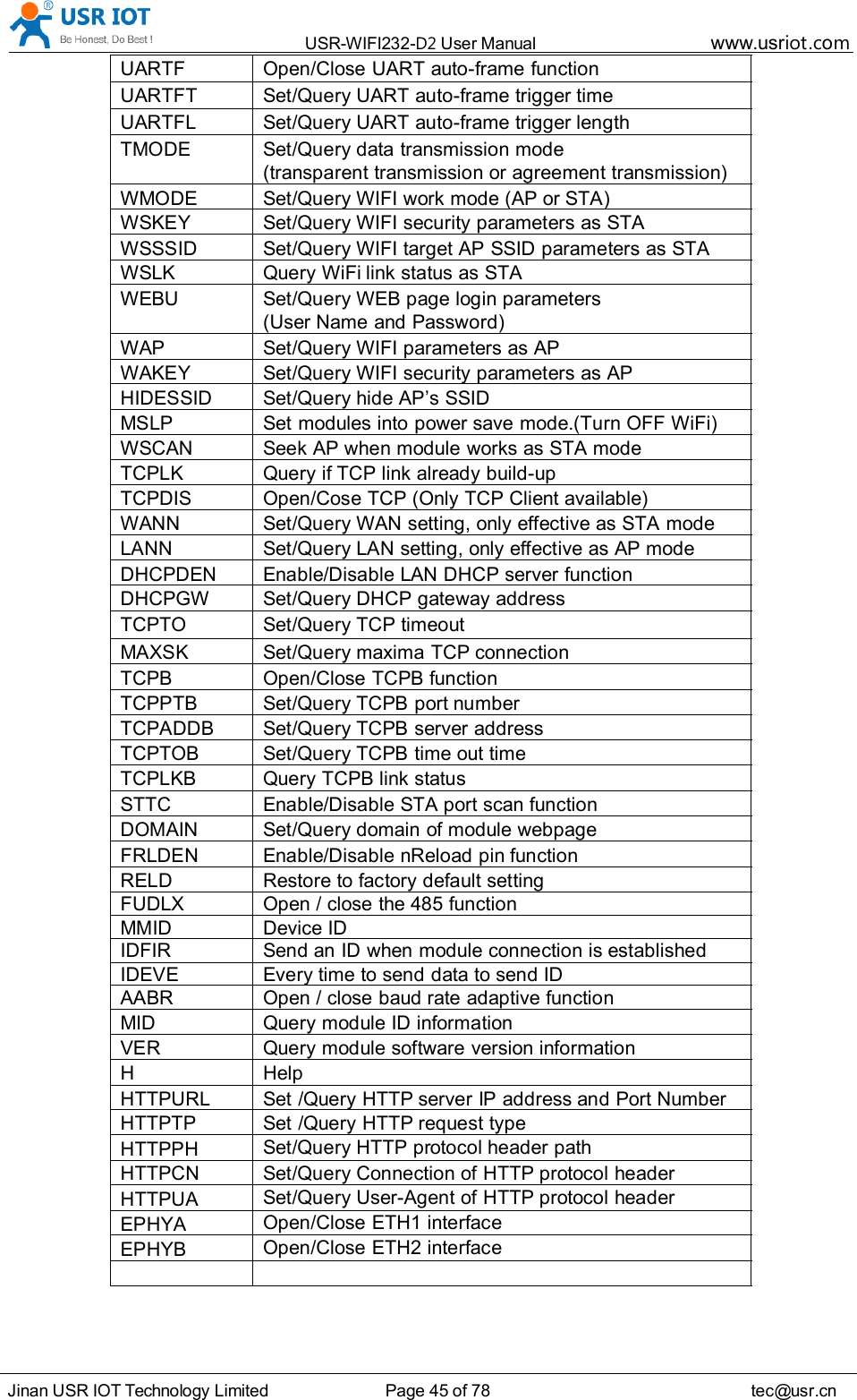
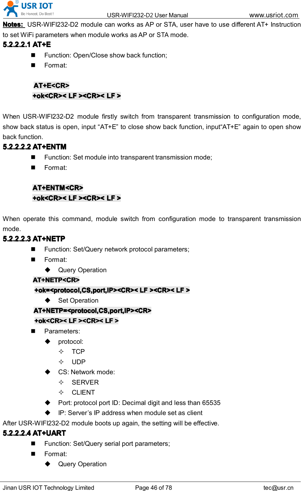
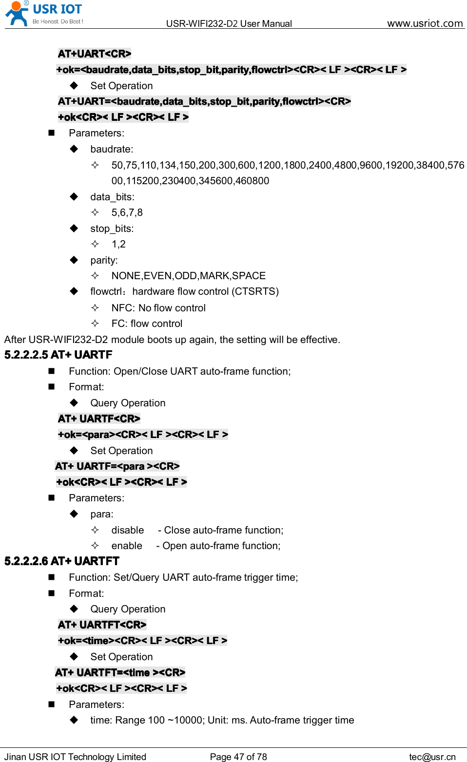
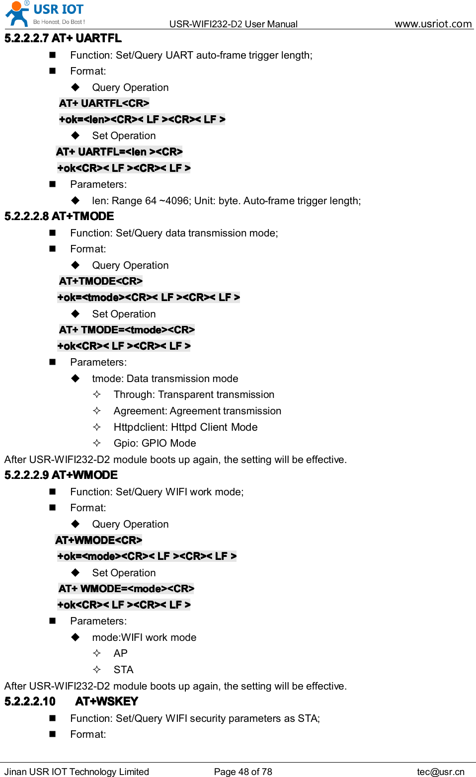
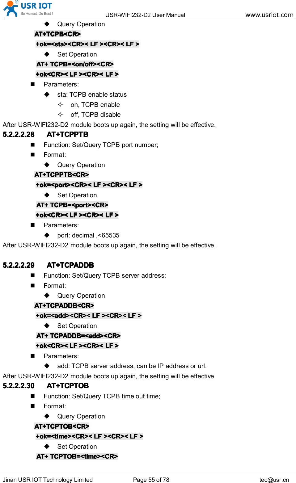
![USR-WIFI232- D2 User Manual www.usr iot .comJinan USR IOT Technology Limited Page 43 of 78 tec@usr.cnClick “ Open Com ” , send “ +++a ” , it will reply +ok in left side, then type in and send the commandyou need to send, then click “ AT+RELD ” to restore, then parameters saved.Figure 43 softwaresoftwaresoftwaresoftware ofofofof USR-WIFI232-SetupUSR-WIFI232-SetupUSR-WIFI232-SetupUSR-WIFI232-SetupAbove is by COM, also you can send by WIFI:First, connect with PC, open the software, see Net partFigure 44 SearchSearchSearchSearch modulemodulemodulemoduleClick search, then will show module, click module then you can send command.5.2.2.1 Instruction Syntax FormatAT+Instruction protocol is based on the instruction of ASCII command style, the description ofsyntax format as follow.FormatFormatFormatFormat DescriptionDescriptionDescriptionDescription< >: Means the parts must be included[ ]: Means the optional part](https://usermanual.wiki/Jinan-USR-IOT-Technology/WIFI232D2A.Manual/User-Guide-2375447-Page-43.png)
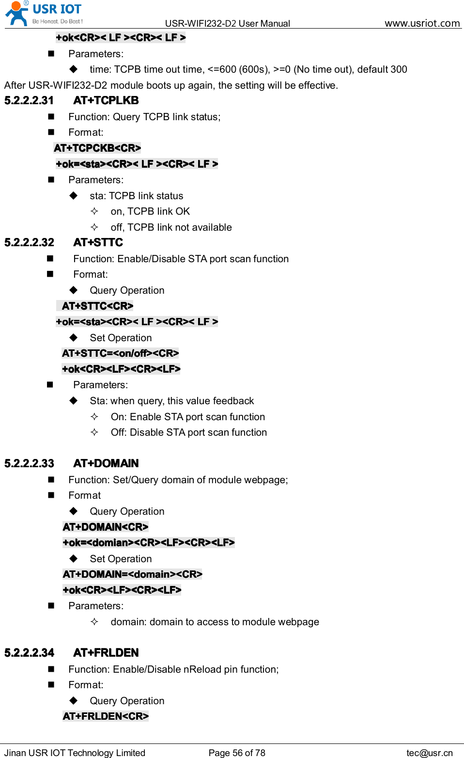
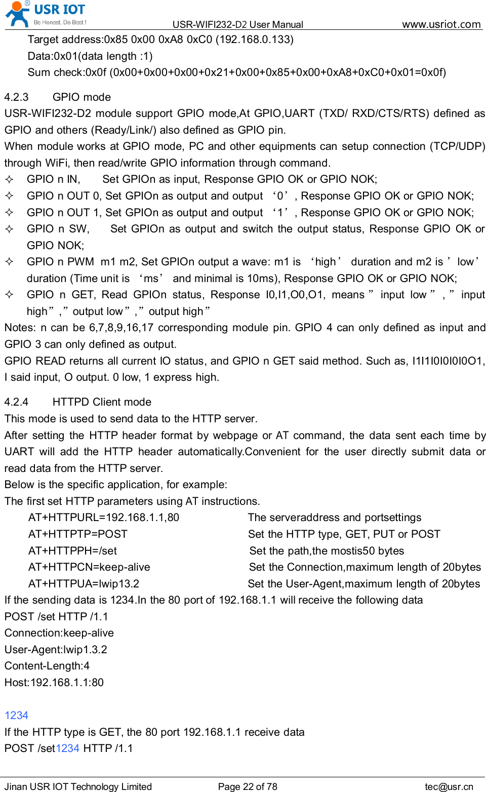
![USR-WIFI232- D2 User Manual www.usr iot .comJinan USR IOT Technology Limited Page 44 of 78 tec@usr.cnCommandCommandCommandCommand MessageMessageMessageMessageAT+<CMD>[op][para-1,para-2,para-3,para-4AT+<CMD>[op][para-1,para-2,para-3,para-4AT+<CMD>[op][para-1,para-2,para-3,para-4AT+<CMD>[op][para-1,para-2,para-3,para-4 ………… ]<CR>]<CR>]<CR>]<CR>AT+: Prefix of command message;CMD: Command string;[op]: Symbol of command operator,“ = ” : The command requires parameters input;“ NULL ” : Query the current command parameters setting;[para-n]: Parameters input for setting if required;<CR> : ” Enter ” Key, it ’ s 0x0a or 0x0d in ASCII;NotesNotesNotesNotes : When input AT+Instruction, “ AT+<CMD> ” character will display capital letter automaticand other parts will not change as you input.ResponseResponseResponseResponse MessageMessageMessageMessage+<RSP>[op]+<RSP>[op]+<RSP>[op]+<RSP>[op] [para-1,para-2,para-3,para-4[para-1,para-2,para-3,para-4[para-1,para-2,para-3,para-4[para-1,para-2,para-3,para-4 ………… ]<CR><LF><CR><LF>]<CR><LF><CR><LF>]<CR><LF><CR><LF>]<CR><LF><CR><LF>+: Prefix of response message;RSP: Response string;“ ok ” : Success“ ERR ” : Failure[op] : =[para-n]: Parameters if query command or Error code when error happened;<CR>: ASCII 0x0d;<LF>: ASCIII 0x0a;ErrorErrorErrorError CodeCodeCodeCodeTable 8 ErrorErrorErrorError CodeCodeCodeCode DescriptionDescriptionDescriptionDescription USR-WIFI232-D2USR-WIFI232-D2USR-WIFI232-D2USR-WIFI232-D2 WebWebWebWeb AccessAccessAccessAccess DefaultDefaultDefaultDefault SettingSettingSettingSettingErrorErrorErrorError CodeCodeCodeCode DescriptionDescriptionDescriptionDescription-1 Invalid Command Format-2 Invalid Command-3 Invalid Operation Symbol-4 Invalid Parameter-5 Operation Not Permitted5.2.2.2 AT+ Instruction SetTable 9 AT+AT+AT+AT+ InstructionInstructionInstructionInstruction SetSetSetSet ListListListListInstructionInstructionInstructionInstruction DescriptionDescriptionDescriptionDescription<null> NULLE Open/Close show back functionENTM Set module into transparent transmission modeNETP Set/Query network protocol parametersUART Set/Query serial port parameters](https://usermanual.wiki/Jinan-USR-IOT-Technology/WIFI232D2A.Manual/User-Guide-2375447-Page-44.png)