John Deere L1742 Users Manual
L2548 to the manual 6e6996c1-e64c-4a61-aaf7-3c5148b8419b
2015-02-03
: John-Deere John-Deere-L1742-Users-Manual-464881 john-deere-l1742-users-manual-464881 john-deere pdf
Open the PDF directly: View PDF ![]() .
.
Page Count: 76
- Introduction
- Product Identification
- Table of Contents
- Safety
- Understanding The Machine Safety Labels
- DANGER: ROTATING BLADES CUT OFF ARMS AND LEGS
- WARNING: AVOID SERIOUS INJURY OR DEATH
- DANGER - CAUTION: POISON
- DANGER: ROTATING BLADE-THROWN OBJECTS
- DANGER: ROTATING BLADE
- WARNING
- Emission Control System Certification Label
- Emission Compliance Period
- Certification
- Operating Safely
- Checking Mowing Area
- Parking Safely
- Rotating Blades are Dangerous
- Avoid Tipping
- Keep Riders Off
- Towing Loads Safely
- Wear Appropriate Clothing
- Driving Safely on Public Roads
- Practice Safe Maintenance
- Prevent Fires
- Tire Safety
- Handling Fuel Safely
- Handling Waste Product and Chemicals
- Operating
- Daily Operating Checklist
- Avoid Damage to Plastic and Painted Surfaces
- Operator Station Controls
- Miscellaneous Controls
- Miscellaneous Accessories
- Adjusting Seat
- Adjusting Cutting Height
- Adjusting Mower Deck Wheels
- Checking Mower Level
- Adjusting Mower Level
- Testing Safety Systems
- Testing Park Brake Switch
- Testing Park Brake
- Testing PTO Switch
- Testing Seat Switch
- Testing Reverse Implement Option (RIO)
- Using the Park Brake
- Using the Fuel Gauge
- Using the Service Reminder
- Starting the Engine
- Idling Engine
- Stopping the Engine
- Using Headlights
- Using Travel Controls on Gear Transmission
- Using Travel Controls on Automatic Transmission
- Using The Reverse Implement Option (RIO)
- Using Cruise Control (On Models 17.542, 2048 and 2548 Only)
- Using Mower Lift Lever
- Using Mower
- Pushing Machine
- Unplugging Mower or Optional Bagger
- Transporting Machine on Trailer
- Using Mulch Cover
- Using the Power Port (Models 2048 and 2548 Only)
- Using CargO Mount System
- Using Storage Accessories
- Using Weights
- Using Tire Chains
- Mowing Tips
- Replacement Parts
- Service Intervals
- Service Lubrication
- Service Engine
- Engine Warranty Maintenance Statement
- Avoid Fumes
- Engine Oil
- Checking Engine Oil Level
- Changing Engine Oil and Filter
- Cleaning Air Intake Screen and Engine Fins
- Checking and Cleaning Air Cleaner Elements (Model 1742)
- Checking and Cleaning Air Cleaner Elements (Model 17.542)
- Checking and Cleaning Air Cleaner Elements (Models 2048 and 2548)
- Checking Spark Plug
- Adjusting Carburetor
- Replacing Fuel Filter
- Service Transmission
- Service Mower
- Installing or Removing Mower Drive Belt at Engine Drive Sheave (48 (3-in-1) Only)
- Removing Mower
- Installing Mower
- Replacing Mower Drive Belt (42 (3 in 1))
- Replacing Mower Drive Belt (48 (3 in 1))
- Adjusting Mower Belt Tension (42 (3 in 1) Only)
- Adjusting Spindle Brakes (42 (3 in 1) Only)
- Checking for Bent Mower Blades
- Servicing Mower Blades
- Sharpening Blades
- Balancing Blades
- Service Electrical
- Service Miscellaneous
- Troubleshooting
- Storage
- Assembly
- Specifications
- Warranty
- Index
- Notes
- Quality Statement
- Service Record

OMGX20928 I1
GX20928
I1 Scotts Lawn Tractors
L1742, L17.542, L2048 and L2548
OPERATOR’S MANUAL
North American Version
Litho in U.S.A.
Introduction
INTRODUCTION
Introduction
Thank You for Purchasing a Scotts Product
We appreciate having you as a customer and wish you
many years of safe and satisfied use of your machine.
Using Your Operator’s Manual
This manual is an important part of your machine and
should remain with the machine when you sell it.
Reading your operator’s manual will help you and others
avoid personal injury or damage to the machine.
Information given in this manual will provide the operator
with the safest and most effective use of the machine.
Knowing how to operate this machine safely and correctly
will allow you to train others who may operate this machine.
This manual and safety signs on your machine may also be
available in other languages (see your John Deere dealer
to order).
Sections in your operator’s manual are placed in a specific
order to help you understand all the safety messages and
learn the controls so you can operate this machine safely.
You can also use this manual to answer any specific
operating or servicing questions. A convenient index
located at the end of this book will help you to find needed
information quickly.
The machine shown in this manual may differ slightly from
your machine, but will be similar enough to help you
understand our instructions.
RIGHT-HAND and LEFT-HAND sides are determined by
facing in the direction the machine will travel when going
forward. When you see a broken line arrow (------>), the
item referred to is hidden from view.
Before delivering this machine, your dealer performed a
predelivery inspection to ensure best performance.
Special Messages
Your manual contains special messages to bring attention
to potential safety concerns, machine damage as well as
helpful operating and servicing information. Please read all
the information carefully to avoid injury and machine
damage.
NOTE: General information is given throughout the
manual that may help the operator in the operation or
service of the machine.
CALIFORNIA Proposition 65 Warning
c CAUTION: Avoid injury! This symbol and text
highlight potential hazards or death to the
operator or bystanders that may occur if the
hazards or procedures are ignored.
IMPORTANT: Avoid damage! This text is used to tell
the operator of actions or conditions that might
result in damage to the machine.
W
arning:
g
The Engine Exhaust from
this product contains chemicals kno
w
n to the
State of California to cause cancer, bir
t
h
defects or other reproductive harm
.
Product Identification
PRODUCT IDENTIFICATION
Product Identification
Record Identification Numbers
Scotts Lawn Tractors
L1742, L17.542, L2048 and L2548
PIN ( 010001- )
If you need to contact an Authorized Service Center for
information on servicing, always provide the product model
and identification numbers.
You will need to locate the model and serial number for the
machine and for the engine of your machine and record the
information in the spaces provided below.
DATE OF PURCHASE:
_________________________________________
DEALER NAME:
_________________________________________
DEALER PHONE:
_________________________________________
MX10531a
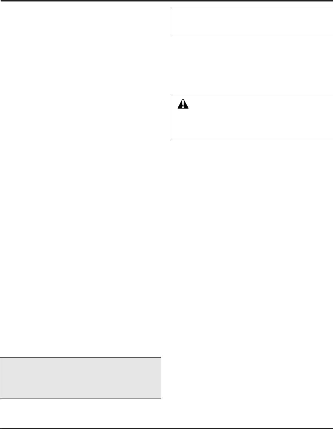
PRODUCT IDENTIFICATION NUMBER (A):
__ __ __ __ __ __ __ __ __ __ __ __ __ __ __ __ __
ENGINE SERIAL NUMBER (B):
__ __ __ __ __ __ __ __ __ __ __ __ __ __ __ __ __
MOWER DECK SERIAL NUMBER (C):
__ __ __ __ __ __ __ __ __ __ __ __ __ __ __ __ __
Register Your Product and Warranty Online
To register your product through the Internet, simply go to
www.JohnDeereWarrantyRegistration.com. Completing the
information, either online or with the product warranty card,
will ensure the customer that their product receives all post
sales service and important product information.
B
C
A

Table of Contents
TABLE OF CONTENTS
All information, illustrations and
specifications in this manual are based
on the latest information at the time of
publication. The right is reserved to
make changes at any time without
notice.
COPYRIGHT© 2001
Deere & Co.
John Deere Worldwide Commercial and
Consumer Equipment Division
All rights reserved
Previous Editions
COPYRIGHT©
OMGX20928 I1 - English
Table of Contents
Safety .....................................................................................................................................................................................1
Operating................................................................................................................................................................................9
Replacement Parts...............................................................................................................................................................27
Service Intervals...................................................................................................................................................................28
Service Lubrication...............................................................................................................................................................30
Service Engine .....................................................................................................................................................................32
Service Transmission ...........................................................................................................................................................39
Service Mower......................................................................................................................................................................40
Service Electrical..................................................................................................................................................................47
Service Miscellaneous..........................................................................................................................................................50
Troubleshooting ....................................................................................................................................................................53
Storage.................................................................................................................................................................................57
Assembly ..............................................................................................................................................................................59
Specifications .......................................................................................................................................................................62
Warranty ...............................................................................................................................................................................64
Index.....................................................................................................................................................................................70
Safety - 1
SAFETY
Safety
Understanding The Machine Safety Labels
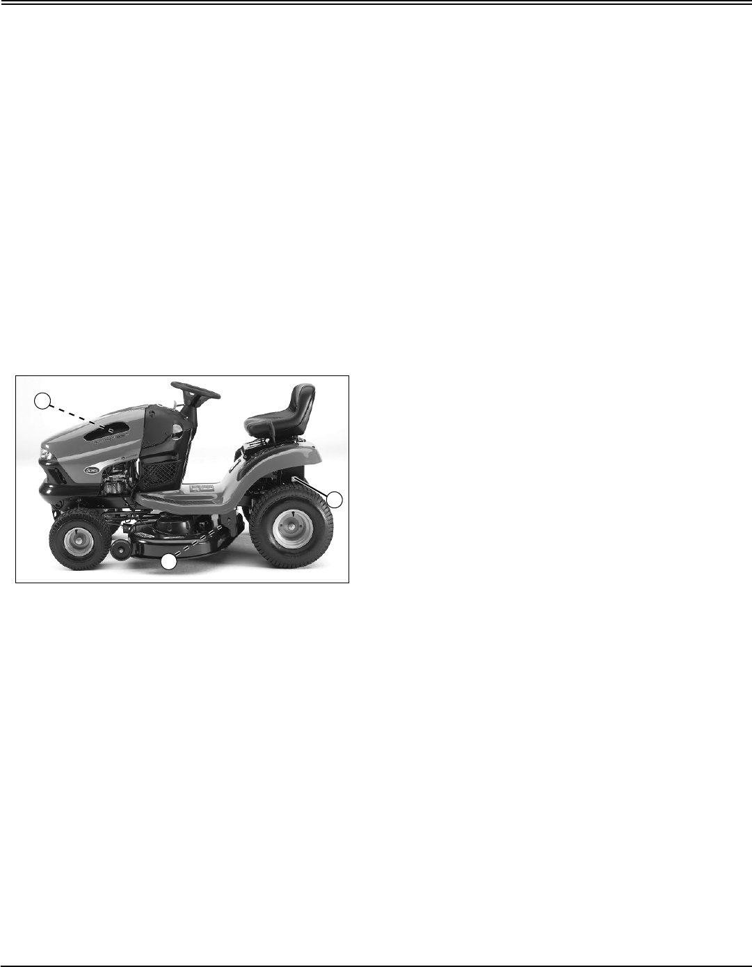
Safety Alert Symbol
The machine safety labels shown in this section are placed
in important areas on your machine to draw attention to
potential safety hazards.
On your machine safety labels, the words DANGER,
WARNING, and CAUTION are used with this safety-alert
symbol. DANGER identifies the most serious hazards.
The operator’s manual also explains any potential safety
hazards whenever necessary in special safety messages
that are identified with the word, CAUTION, and the safety-
alert symbol.
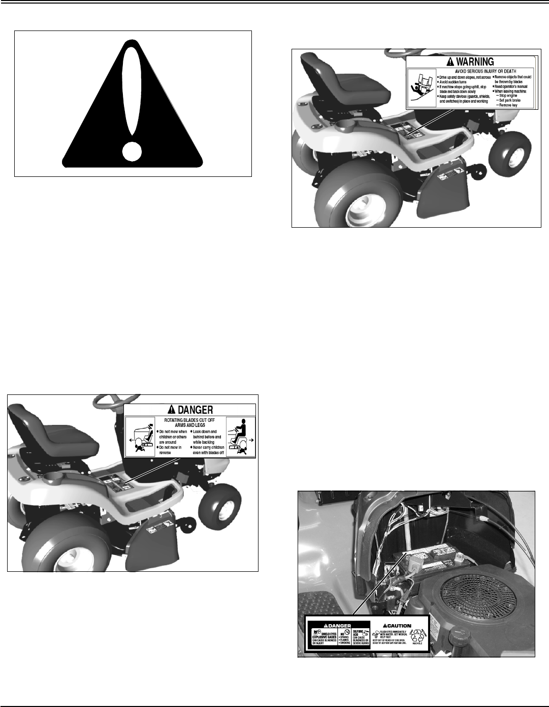
DANGER: ROTATING BLADES CUT OFF
ARMS AND LEGS
GX20207; MX7692
•Do not mow when children or others are around.
•Do not mow in reverse.
•Look down and behind before and while backing.
•Never carry children even with blades off.
WARNING: AVOID SERIOUS INJURY OR
DEATH
GX20207; MX7692
•Drive up and down slopes, not across.
•Avoid sudden turns.
•If machine stops going uphill, stop blades and back
down slowly.
•Keep safety devices (guards, shields, and switches) in
place and working.
•Remove objects that could be thrown by blades.
•Read operator’s manual.
•When leaving machine:
–Stop engine
–Set park brake
–Remove key
DANGER - CAUTION: POISON
M128699; MX7686
Picture Note: Located on battery
Safety - 2
SAFETY
•Shield eyes, explosive gases can cause blindness or
injury.
•No sparks, flames, smoking.
•Sulfuric acid can cause blindness or severe burns.
•Flush eyes immediately with water. Get medical help
fast.
•Keep out of reach of children.
•Do not tip.
•Keep vent caps tight and level.
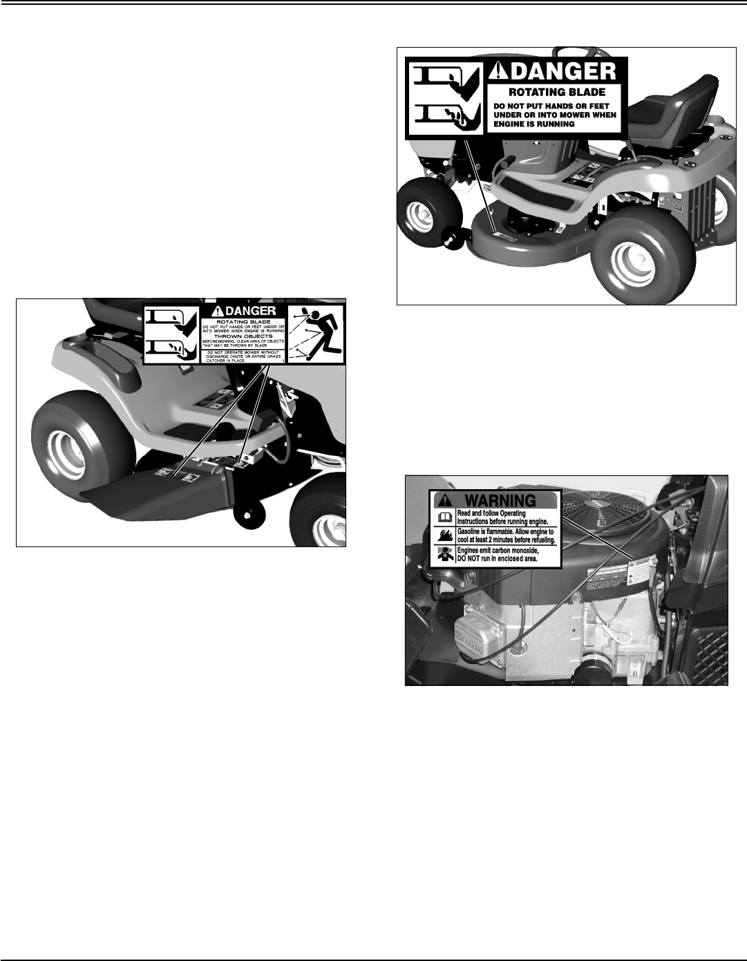
DANGER: ROTATING BLADE-THROWN
OBJECTS
MX7693; M89504
Picture Note: Two on right side of deck. 42 (3 in 1)
shown.
•Rotating blade.
•Do not put hands or feet under or into mower when
engine is running.
•Thrown objects.
•Before mowing, clear area of objects that may be thrown
by blade.
•Do not operate mower without discharge chute or entire
grass catcher in place.
DANGER: ROTATING BLADE
MX7694; M118610
Picture Note: Located on left side of deck. 42 (3 in
1) shown.
•Do not put hands or feet under or into mower when
engine is running.
WARNING
MX7683; MX4878
Picture Note: Located on 20 and 25 hp Briggs and
Stratton engines.
•Read and follow Operating Instructions before running
engine.
•Gasoline is flammable. Allow engine to cool at least 2
minutes before refueling.
•Engines emit carbon monoxide, DO NOT run in
enclosed area.
Safety - 3
SAFETY
Emission Control System Certification Label
NOTE: Tampering with emission controls and
components by unauthorized personnel may result in
severe fines or penalties. Emission controls and
components can only be adjusted by EPA and/or CARB
authorized service centers. Contact your John Deere
Commercial and Consumer Equipment Retailer
concerning emission controls and component
questions.
The presence of an emissions label signifies that the
engine has been certified with the United States
Environmental Protection Agency (EPA) and/or California
Air Resources Board (CARB).
The emissions warranty applies only to those engines
marketed by John Deere that have been certified by the
EPA and/or CARB; and used in the United States and
Canada in off-road mobile equipment.
Emission Compliance Period
If your engine has the emission compliance category listed
on the emission control system certification or air index
label, this indicates the number of operating hours for which
the engine has been certified to meet EPA and/or CARB
emission requirements. The following table provides the
engine compliance period in hours associated with the
category found on the certification label.
Certification
Your mower has been certified by an independent
laboratory for compliance with American National Standard
B-71.1, “Safety Specifications” for Power Lawn Mowers,
Lawn and Garden Tractors, and Lawn Tractors.
Operating Safely
MIF
•Read, understand and follow all instructions in the
manual, on the machine and on the safety video before
starting.
•Only allow responsible adults, who are familiar with the
instructions to operate the machine.
•Inspect machine before you operate. Be sure hardware
is tight. Repair or replace damaged, badly worn, or missing
parts. Be sure guards and shields are in good condition
and fastened in place. Make any necessary adjustments
before you operate.
•Do not operate mower without discharge chute or entire
grass catcher in place.
•Check brake action before you operate. Adjust or
service brakes as necessary.
•Stop machine if anyone enters the area.
•If you hit an object, stop the machine and inspect it.
Make repairs before you operate. Keep machine and
attachments properly maintained and in good working
order.
•Be aware of the mower discharge direction and make
sure that no one is in the path of the discharge direction.
•Do not leave machine unattended when it is running.
•Only operate during daylight or with good artificial light.
•Be careful of traffic when operating near or crossing
roadways.
•Do not wear radio or music headphones while operating
the machine. Safe operation requires your full attention.
•Older adults are involved in a large percentage of riding
mower accidents involving injury. These operators should
evaluate their ability to operate a mower safely enough to
protect the operator and others from serious injury.
Agency Category Hours
EPA C 250
EPA B 500
EPA A 1000
CARB Moderate 125
CARB Intermediate 250
CARB Extended 500
Safety - 4
SAFETY
Checking Mowing Area
•Clear mowing area of objects that might be thrown.
Keep people and pets out of mowing area.
•Study mowing area. Set up a safe mowing pattern. Do
not mow where traction or stability is doubtful.
•Test drive area with mower lowered but not running.
Slow down when you travel over rough ground.
Parking Safely
1. Stop machine on a level surface, not on a slope.
2. Disengage mower blades.
3. Lower attachments to the ground.
4. Lock the park brake.
5. Stop the engine.
6. Remove the key.
7. Wait for engine and all moving parts to stop before you
leave the operator’s seat.
Rotating Blades are Dangerous
HELP PREVENT SERIOUS OR FATAL ACCIDENTS:
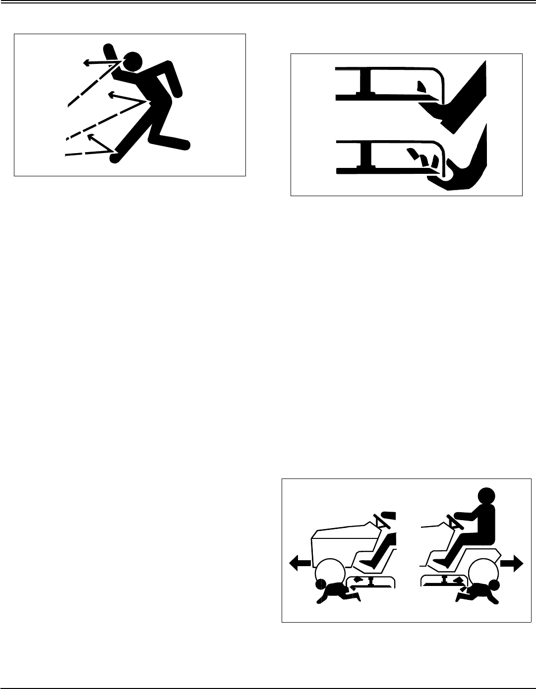
•Rotating blades can cut off arms and legs, and throw
objects. Failure to observe safety instructions could result
in serious injury or death.
•Keep hands, feet and clothing away from mower deck
when engine is running.
•Be alert at all times, drive forward carefully. People,
especially children can move quickly into the mowing area
before you know it.
•Before backing up, stop mower blades or attachments
and look down and behind the machine carefully, especially
for children.
•Do not mow in reverse.
•Shut off blades when you are not mowing.
•Do not operate machine if you are under the influence of
drugs or alcohol.
•Park machine safely before inspecting, removing, or
unplugging mower or bagger.
PROTECT CHILDREN:
•Tragic accidents can occur if the operator is not alert to
the presence of children. Keep children out of the mowing
area and under the watchful care of another responsible
Safety - 5
SAFETY
adult.
•Never assume that children will remain where you last
saw them. Children are attracted to mowing activity, stay
alert to the presence of children.
•Keep children indoors when you are mowing. Turn the
machine off if a child enters the mowing area.
•Use extra care when you come to blind corners, shrubs,
trees, or other objects that may block your vision.
•Do not let children or an untrained person operate the
machine.
•Do not carry or let children ride on any attachment or
machine even with the blades off. Do not tow children in a
cart or trailer.
Avoid Tipping
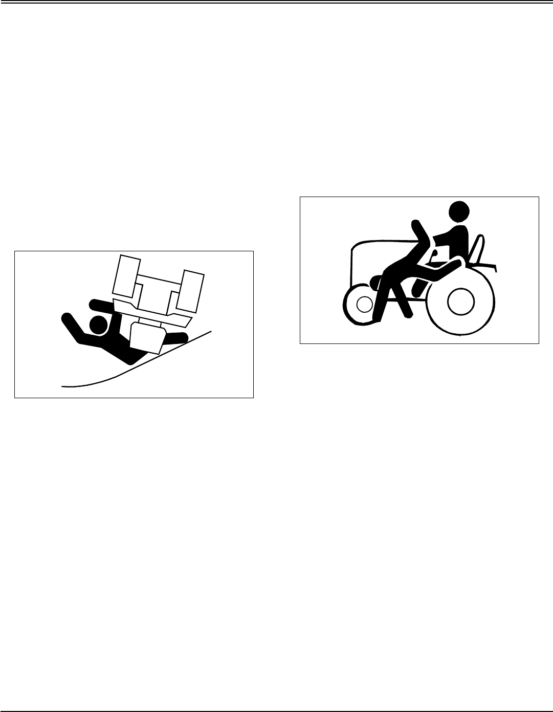
•Slopes are a major factor related to loss-of-control and
tip-over accidents, which can result in severe injury or
death. All slopes require extra caution. If you cannot back
up the slope or if you feel uneasy on it, do not mow it.
•Keep all movement on slopes slow and gradual. Do not
make sudden changes in speed or direction.
•Slow down before you make a sharp turn or operate on
a slope. Choose a low gear or speed so that you will not
have to stop or shift while on the slope.
•Do not turn on slopes unless necessary. Turn slowly and
turn downhill. Do not shift to neutral and coast downhill.
•Stay alert for holes and other hidden hazards in the
terrain. Uneven terrain could overturn the machine. Tall
grass can hide obstacles.
•Keep away from drop-offs, ditches and embankments.
•Use extra care with grass catchers or other
attachments. These can change the stability of the
machine. Do not use grass catcher on steep slopes.
•Use recommended weights for added stability when
operating on slopes or using front or rear mounted
attachments. Remove weights when not required.
•Drive up and down a hill - not across.
•Do not stop when going up hill or down hill. If machine
stops going up hill, disengage mower blades and back
down slowly.
•Mowing when grass is wet can cause reduced traction
and sliding.
•Do not try to stabilize the machine by putting your foot
on the ground.
Keep Riders Off
MIF
•Only allow the operator on the machine. Keep riders off.
•Riders on the machine or attachment may be struck by
foreign objects or thrown off the machine causing serious
injury.
•Riders obstruct the operator’s view resulting in the
machine being operated in an unsafe manner.
Towing Loads Safely
•Limit loads to those you can safely control. Use only
approved hitches when pulling loads or using heavy
equipment. Use counterweights or wheel weights as
required in this manual or your attachment manual.
•Do not tow children in a cart or trailer.
•Travel slowly and allow extra distance to stop.
•Follow the manufacturer’s recommendation for weight
limits for towed equipment and towing on slopes.
•Tow only with a machine that has a hitch designed for
towing. Do not attach towed equipment except at the hitch
point.
•On slopes, the weight of towed equipment may cause
loss of traction and loss of control.
Safety - 6
SAFETY
Wear Appropriate Clothing
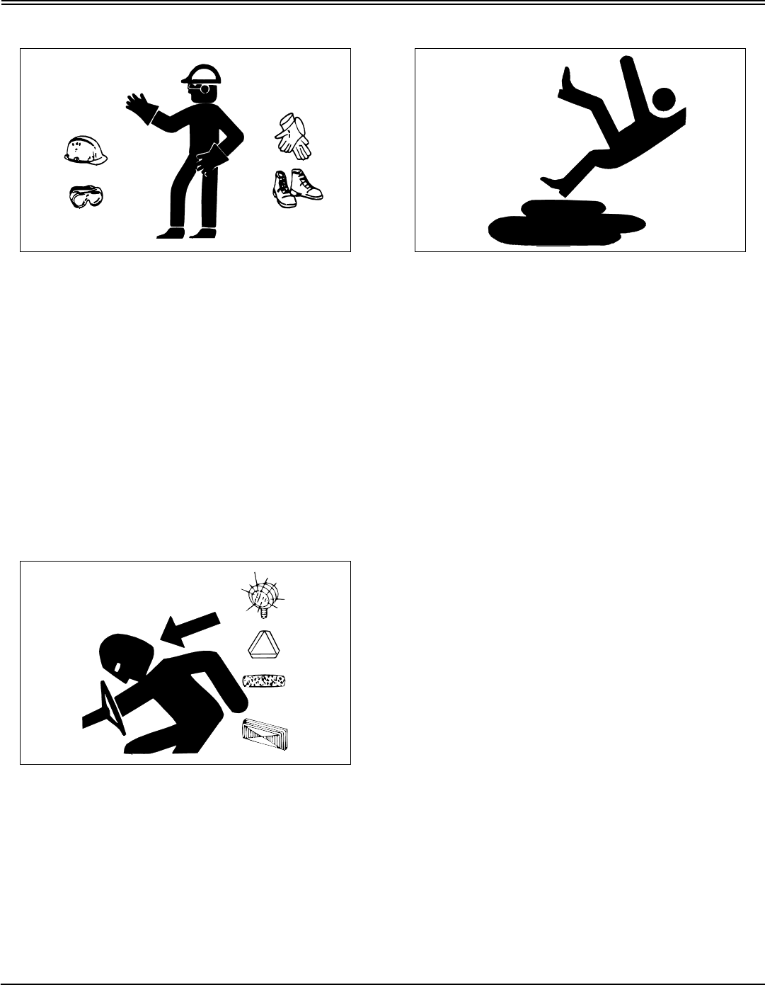
•Wear close fitting clothing and safety equipment
appropriate for the job.
•Always wear safety goggles or safety glasses with side
shields when operating the mower.
•Wear a suitable protective device such as earplugs.
Loud noise can cause impairment or loss of hearing.
•Do not wear radio or music headphones. Safe service
and operation requires your full attention.
Driving Safely on Public Roads
Practice Safe Maintenance
•Understand service procedure before doing work. Keep
area clean and dry.
•Never lubricate, service, or adjust machine while it is
moving. Keep safety devices in place and in working
condition. Keep hardware tight.
•Keep hands, feet, clothing, jewelry, and long hair away
from any moving parts, to prevent them from getting
caught.
•Lower attachments to the ground before servicing
machine. Disengage all power and stop the engine. Lock
park brake and remove the key. Let machine cool.
•Disconnect battery or remove spark plug wire before
making any repairs.
•Keep all nuts and bolts tightened, especially blade
attachment bolts.
•Securely support any machine elements that must be
raised for service work.
•Never run engine unless park brake is locked.
•Keep all parts in good condition and properly installed.
Fix damage immediately. Replace worn or broken parts.
Replace all worn or damaged safety and instruction decals.
•To prevent fires, remove any buildup of grease, oil, or
debris from the machine, especially the engine
compartment.
•Charge battery in an open, well-ventilated area, away
from sparks. Unplug battery charger before connecting or
disconnecting from the battery. Use insulated tools.
•Do not modify machine or safety devices. Unauthorized
modifications may impair its function and safety.
•Do not wear radio or music headphones while servicing
the machine. Safe service requires your full attention.
Avoid personal injury or death resulting from a collision
with another vehicle on public roads:
•Use safety lights and devices. Slow moving machines
when driven on public roads are hard to see, especially at
night.
•Whenever driving on public roads, use flashing
warning lights and turn signals according to local
regulations. Extra flashing warning lights may need to be
installed.
Safety - 7
SAFETY
Prevent Fires
•Never remove fuel cap, or add fuel with engine running
or hot. Allow engine to cool for several minutes.
•Never store equipment with fuel in the tank inside a
building where fumes may reach an open flame or spark.
•Allow engine to cool before storing in any enclosure.
•To reduce fire hazard, keep engine free of grass, leaves,
or excessive grease.
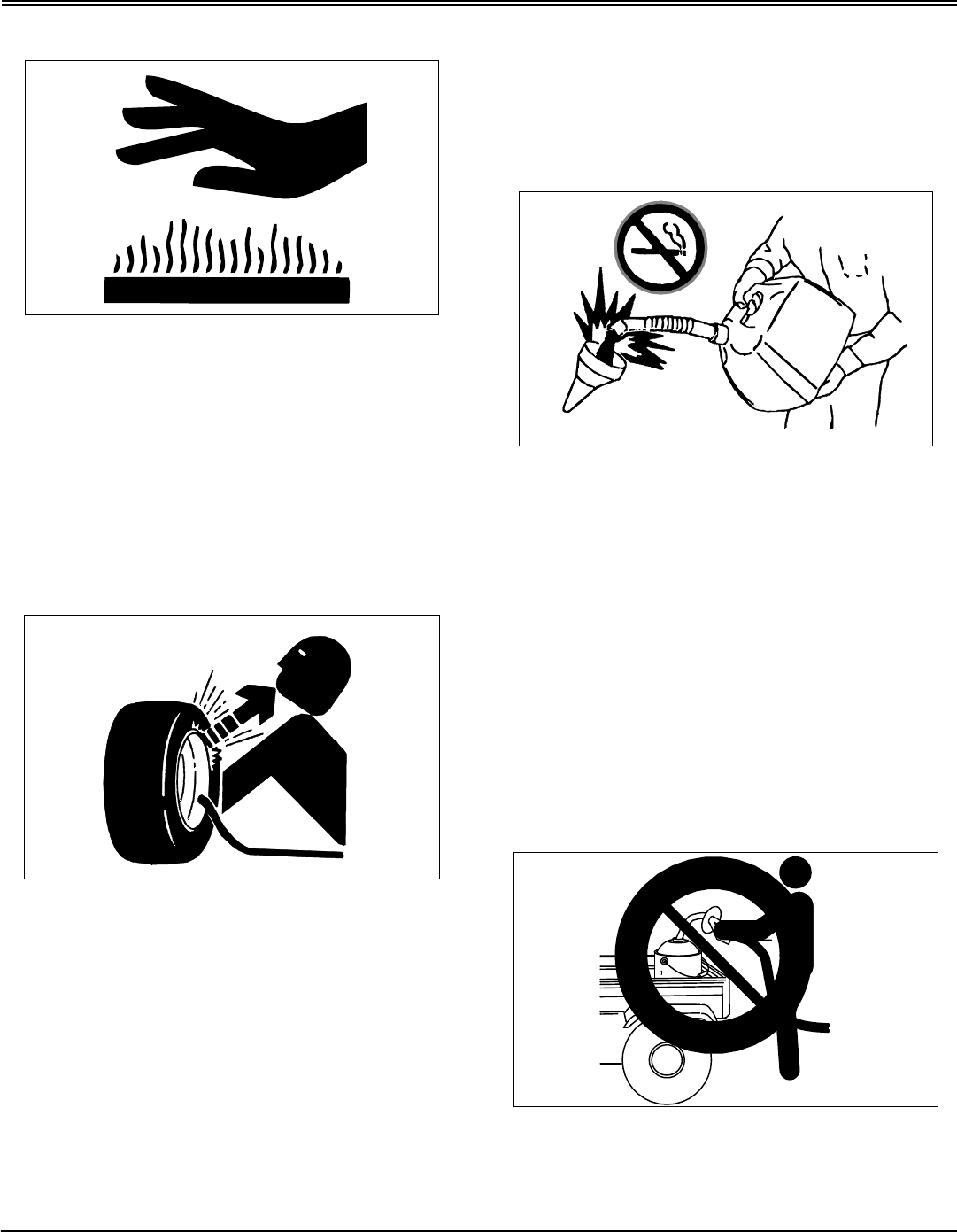
Tire Safety
Explosive separation of a tire and rim parts can cause
serious injury or death:
•Do not attempt to mount a tire without the proper
equipment and experience to perform the job.
•Always maintain the correct tire pressure. Do not inflate
the tires above the recommended pressure. Never weld or
heat a wheel and tire assembly. The heat can cause an
increase in air pressure resulting in a tire explosion.
Welding can structurally weaken or deform the wheel.
•When inflating tires, use a clip-on chuck and extension
hose long enough to allow you to stand to one side and
NOT in front of or over the tire assembly.
•Check tires for low pressure, cuts, bubbles, damaged
rims or missing lug bolts and nuts.
Handling Fuel Safely
Fuel and fuel vapors are highly flammable:
•Do not refuel machine while you smoke, when machine
is near an open flame or sparks, or when engine is running.
stop engine and allow to cool before filling.
•Never remove the fuel cap or add fuel with the engine
running.
•Never fill fuel tank or drain fuel from a machine in an
enclosed area. Fill fuel tank outdoors.
•Prevent fires. Clean up spilled fuel immediately.
•Do not store machine with fuel in tank in a building
where fumes may reach an open flame or spark.
•Prevent fire and explosion caused by static electric
discharge. Use only non-metal, portable fuel containers
approved by the Underwriter’s Laboratory (U.L.) or the
American Society for Testing & Materials (ASTM). If using a
funnel, make sure it is plastic and has no screen or filter.
•Static electric discharge can ignite gasoline vapors in an
ungrounded fuel container. Remove the fuel container from
the bed of a vehicle or the trunk of a car and place on the

Safety - 8
SAFETY
ground away from the vehicle before filling. Keep nozzle in
contact with container opening while filling.
•When practical, remove equipment from trailers or truck
beds and refuel them on the ground. If this is not possible,
use a portable, plastic fuel container to refuel equipment on
a truck bed or trailer.
•For gasoline engines, do not use gas with methanol.
Methanol is harmful to your health and to the environment.
Handling Waste Product and Chemicals
Waste products, such as, used oil, fuel, coolant, brake fluid,
and batteries, can harm the environment and people:
•Do not use beverage containers for waste fluids -
someone may drink from them.
•See your local Recycling Center or John Deere dealer to
learn how to recycle or get rid of waste products.
•A Material Safety Data Sheet (MSDS) provides specific
details on chemical products: physical and health hazards,
safety procedures, and emergency response techniques.
The seller of the chemical products used with your machine
is responsible for providing the MSDS for that product.
Operating - 9
OPERATING
Operating
Daily Operating Checklist
❏Test safety systems.
❏Check tire pressure.
❏Check fuel level.
❏Check engine oil level.
❏Remove grass and debris from machine.
❏Clean air intake screen.
❏Check area below machine for leaks.
Avoid Damage to Plastic and Painted
Surfaces
•Do not wipe plastic parts unless rinsed first.
•Insect repellent spray may damage plastic and painted
surfaces. Do not spray insect repellent near machine.
•Be careful not to spill fuel on machine. Fuel may
damage surface. Wipe up spilled fuel immediately.
•Prolonged exposure to sunlight will damage the hood
surface.
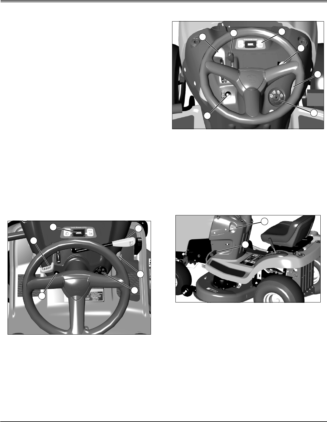
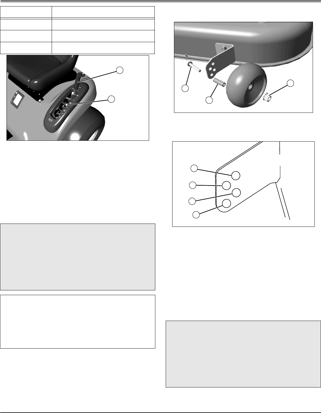
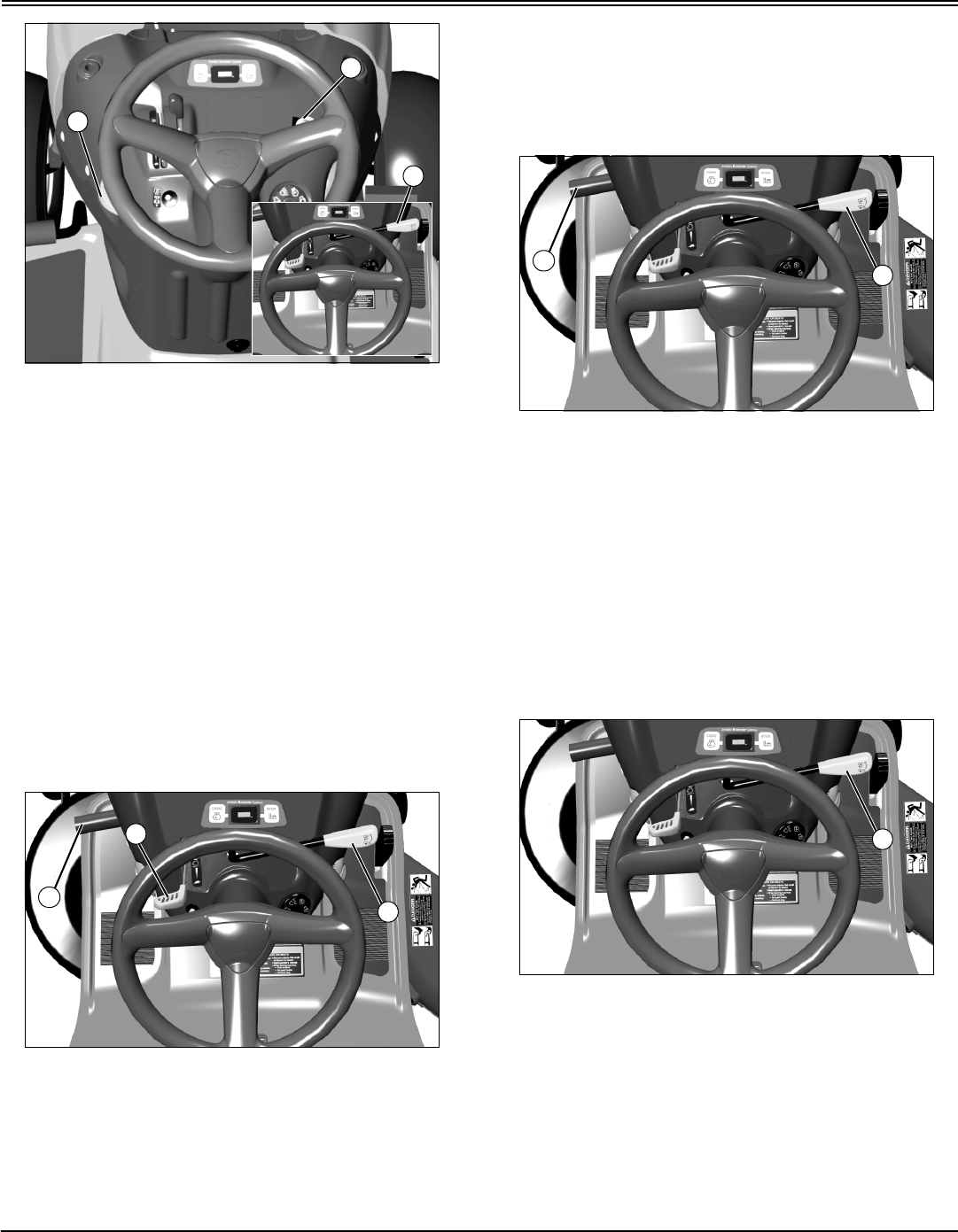
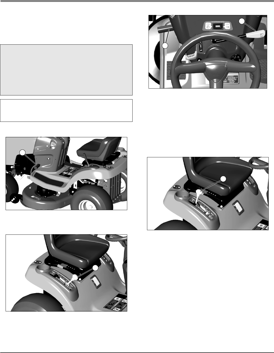
Operator Station Controls
MX7697
Picture Note: Console on Models L1742 and
L17.542; Model L17.542 shown.
A - Throttle/Choke Lever
B - Service Reminder/Hour Meter
C - Mechanical PTO Lever
D - Cruise Control Lever (On Model L17.542 Only);
Storage Retainer (On Model L1742)
E - Key Switch
F - Reverse Implement Option Switch
MX10501
Picture Note: Console on Models L2048 and L2548
A - Throttle Lever
B - Choke Lever
C - Service Reminder/Hour Meter
D - Electric PTO Switch
E - Cruise Control Lever
F - Key Switch
G - Reverse Implement Option Switch
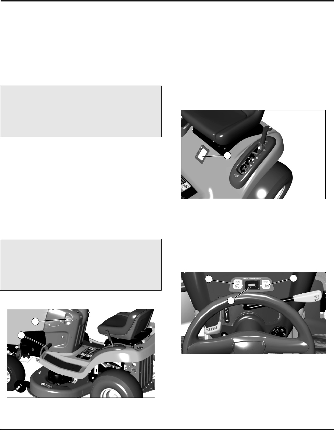
MX7694
A - Park Brake Lock Lever
B - Brake/Clutch Pedal
B
A
C
D
E
F
B
AC
D
E
F
G
A
B
Operating - 10
OPERATING
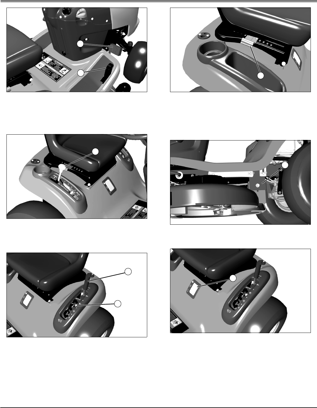
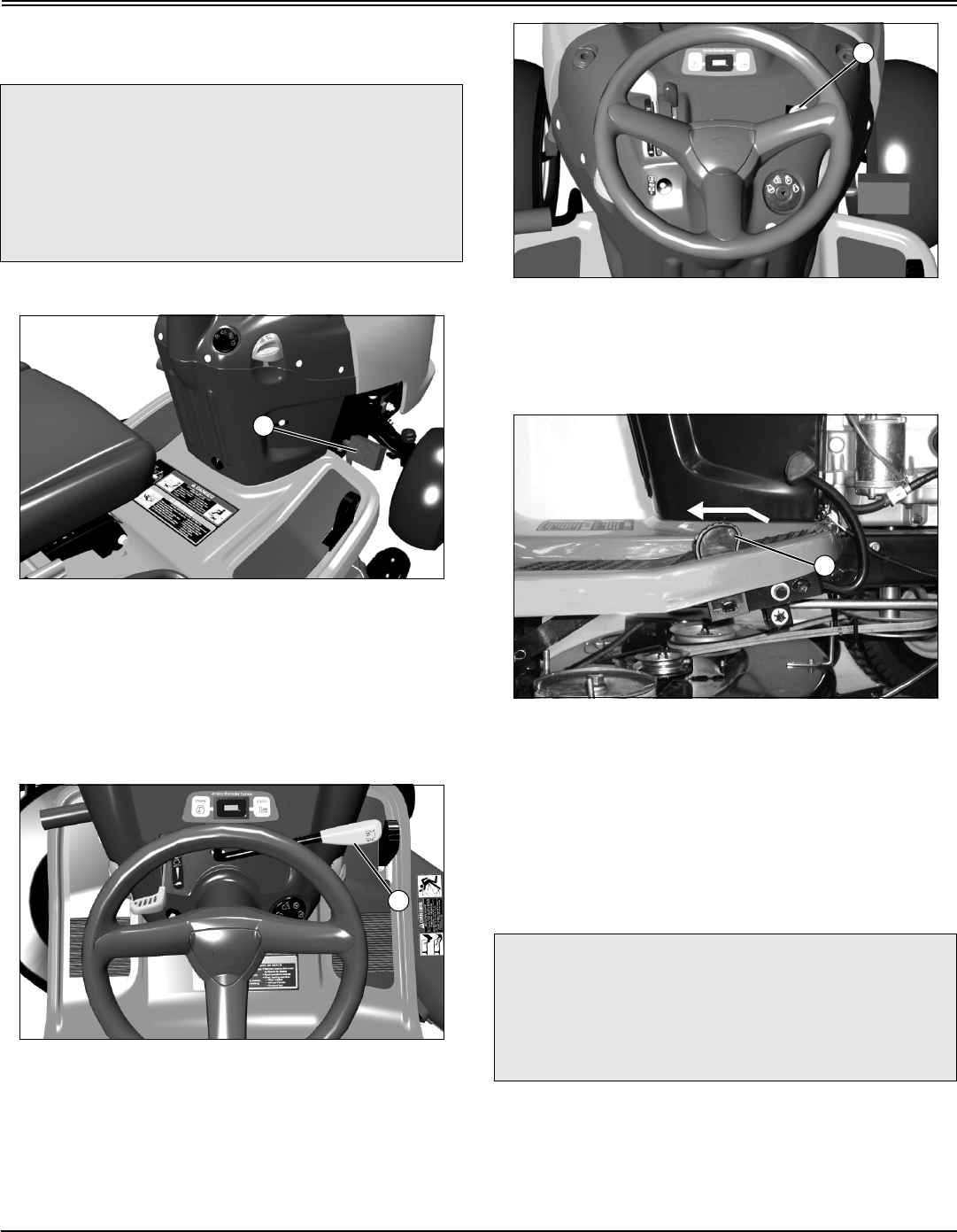
MX7696
Picture Note: Automatic/Foot Control Models Only
A - Forward Travel Pedal
B - Reverse Travel Pedal
MX10503
Picture Note: Gear Model Only
A - Transmission Shift Lever
MX7695
A - Attachment Lift Lever
B - Mower Deck Height Reminder Tab
MX7698
A - Seat Adjustment Lever
Miscellaneous Controls
MX10513
A - Mower Deck Leveling Bracket
MX7695
A - Fuel Level Window
A
B
A
A
B
A
A
A
Operating - 11
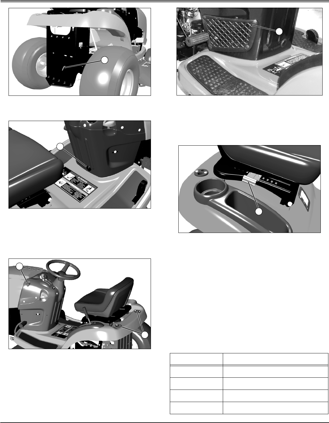
OPERATING
MX7691
A - Free-Wheeling Lever (Foot Control Models)
MX7696
A - Power Port (On models 2048 and 2548 Only)
Miscellaneous Accessories
MX7694
A - Front and Rear CargO Mount System™
MX10524
A - Glove Storage Pocket
Adjusting Seat
MX7698
1. Sit in seat.
2. Lift up on bracket (A).
3. Lean forward and slide seat forward or rearward to
desired position. Do not lean back on seat to push
rearward.
4. Release bracket to lock in position.
Adjusting Cutting Height
Cutting height can be adjusted from approximately 25–100
mm (1–4 in.). When mower deck is in transport position,
cutting height is approximately 100 mm (4 in.).
A
A
A
A
Mower Setting Approximate Cutting Height
1 25 mm (1 in.)
–38 mm (1 1/2 in.)
2 50 mm (2 in.)
–65 mm (2 1/2 in.)
A
A
Operating - 12
OPERATING
MX7695
1. Put attachment lift lever (A) into the slot adjacent to
desired cutting height.
•Slide the height reminder tab (B) to the desired
cutting height for the next time you mow.
2. Adjust mower deck wheels.
Adjusting Mower Deck Wheels
1. Park machine safely. (See Parking Safely in the
SAFETY section.)
2. Inflate tires to the correct pressure.
3. Lower mower deck to the desired mowing position.
NOTE: Bottom of wheels should be approximately 3-13
mm (1/8-1/2 in.) from the ground.
MX10509
4. Check mower wheel position. Remove bolt (A), bushing
(B), and nut (C) and move mower wheels to proper hole.
M92897 mif
A - 38 mm (1.5-In.)
B - 51 mm (2-In.)
C - 64 mm (2.5-In.)
D - 76 mm (3-In.) and above
5. Install bolts, bushings and nuts to lock wheels in
position. Tighten nuts to 34 N•m (25 lb-ft).
Checking Mower Level
NOTE: Mower wheels should not contact the ground
when leveling the deck.
3 75 mm (3 in.)
–90 mm (3 1/2 in.)
4 (Transport) 100 mm (4 in.)
c CAUTION: Avoid injury! Rotating blades are
dangerous. Before adjusting or servicing
mower:
•Disconnect spark plug wire(s) to prevent
engine from starting accidently.
•Always wear gloves when handling mower
blades or working near blades.
IMPORTANT: Avoid damage! The mower deck can
be damaged if mower wheels are adjusted wrong:
•Wheels must not ride on ground supporting
mower weight.
•Check wheel adjustment each time cutting height
is changed.
Mower Setting Approximate Cutting Height
A
B
c CAUTION: Avoid injury! Rotating blades are
dangerous. Before adjusting or servicing
mower:
•Disconnect spark plug wire(s) to prevent
engine from starting accidently.
•Always wear gloves when handling mower
blades or working near blades.
C
A
B
D
C
B
A
Operating - 13
OPERATING
1. Park machine safely. (See Parking Safely in the
SAFETY section.)
2. Inflate tires to the correct pressure.
3. Move mower lift handle to preferred cutting height.
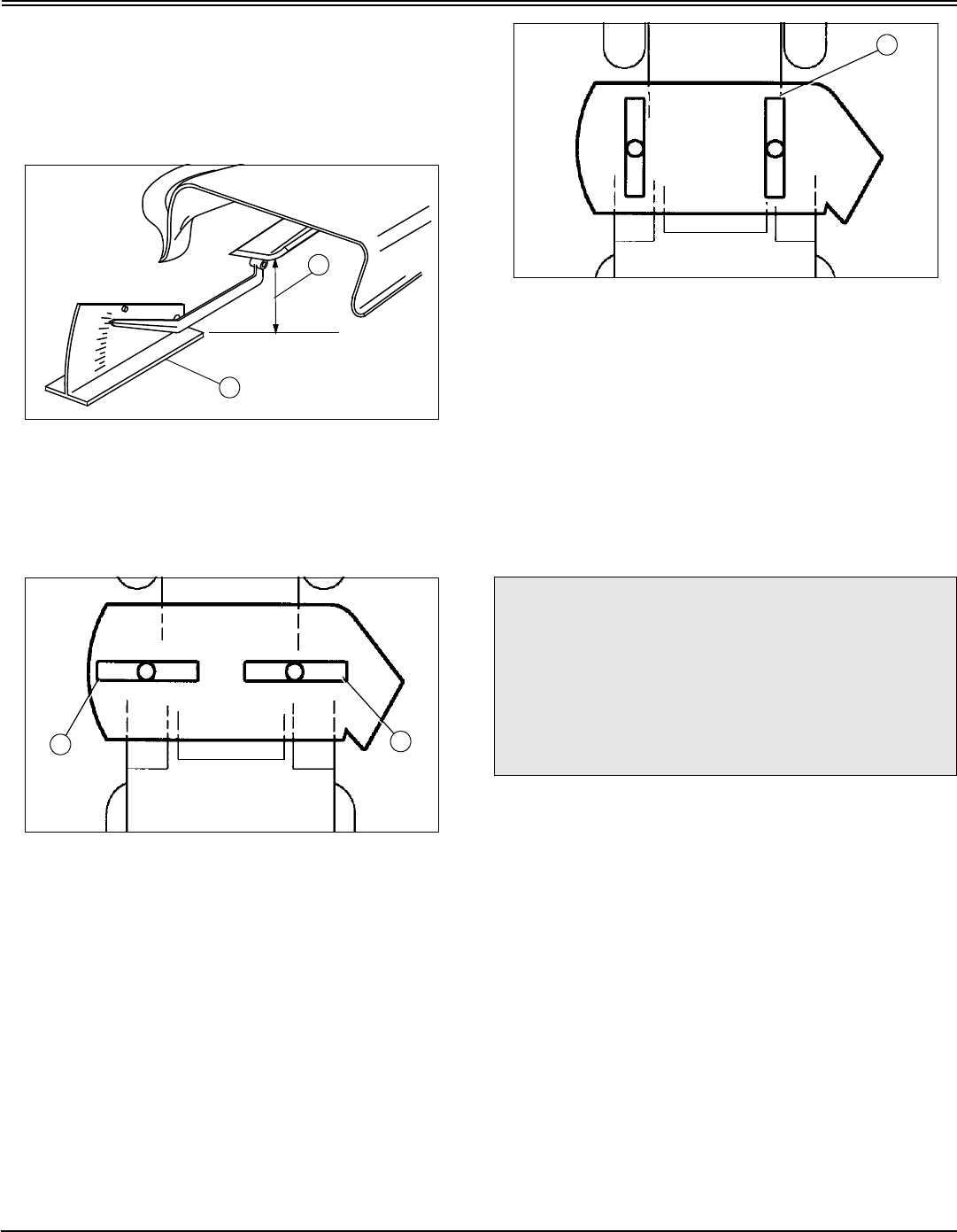
4. Measure mower level (side-to-side).
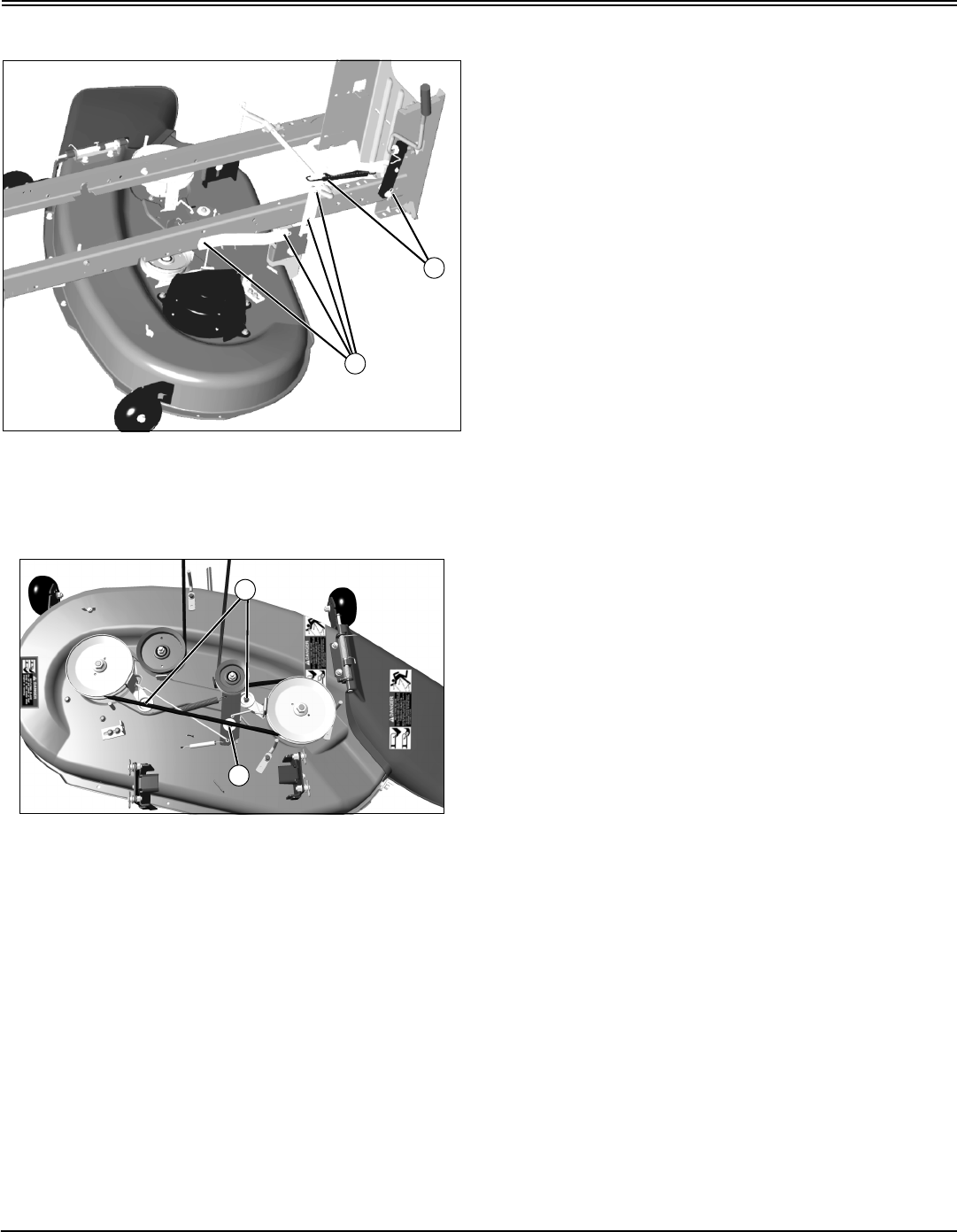
MX4871
Picture Note: A convenient leveling gauge (A)
(AM130907) is available from your John Deere
dealer.
a. Position mower blades as follows and measure from
each outside blade tip (B) to the level surface.
MX4896
Picture Note: 42 (3 in 1) shown.
b. Turn left blade (C) as shown. Hold drive belt and turn
right blade (D) as shown. Take measurement for both
blades.
The difference between blade measurements must not
be more than 3 mm (1/8 in.).
c. Adjust mower level, if necessary.
5. Measure mower level (front-to-rear).
MX4896a
a. Turn right blade (E) so blade tip points straight
forward.
b. Measure from blade tip to the surface. Take
measurement for both blades.
The front blade tip must be 3–6 mm (1/8 -1/4 in.) lower
than rear blade tip.
c. Adjust mower level, if necessary.
Adjusting Mower Level
NOTE: Mower wheels should not contact the ground
when leveling the deck.
1. Make sure machine is on a flat level surface.
2. Raise mower deck to highest position.
A
B
D
C
c CAUTION: Avoid injury! Rotating blades are
dangerous. Before adjusting or servicing
mower:
•Disconnect spark plug wire(s) to prevent
engine from starting accidently.
•Always wear gloves when handling mower
blades or working near blades.
E
Operating - 14
OPERATING
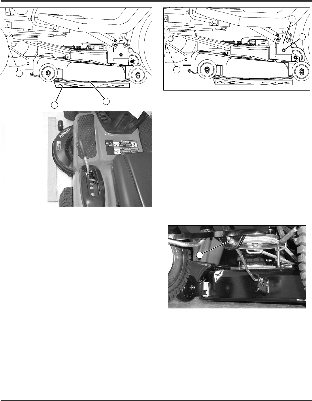
MX7674; MX7674b
Picture Note: 42 (3 in 1) used for illustration.
3. Place a straight 2x4 piece of wood (A) or a 38 mm (1.5
in.) thick block under the edge (B) of each side of mower
deck.
•Shims can be added, on both sides, between block of
wood and mower deck edge to obtain a specific deck
height, if desired.
4. Put mower lift handle in the lowest position, bringing
deck down onto blocks.
5. Check that blocks are positioned under each edge.
Make sure blocks do not interfere with gage wheels.
6. Check that there is no tension on the front draft arm. If
necessary, loosen adjusting nut (C) on front draft arm so
front of deck rests on wood blocks.
7. On 48 (3 in 1) deck: Remove mower drive belt from the
engine drive sheave to release belt tension.
MX7674
8. Loosen leveling nut (D), one on each side, and make
sure bolts and leveling brackets (E) slide freely in slots.
9. Raise lift handle to highest position and then lower back
down to 25 mm (1 in.) cutting height to position the deck
and brackets.
10.Apply slight pressure on leveling brackets (E), one on
each side, by pulling down to remove slack in linkage.
Tighten nuts (D), one on each side, to 55 N•m (40 ft-lbs).
11.Turn adjusting nut (C) on front draft arm clockwise until
deck begins to raise off wood blocks.
12.On 48 (3 in 1): Put lift lever in the lowest position and
install mower drive belt on engine drive sheave.
13.Set preferred cutting height.
14.Check front-to-rear mower level again and adjust if
necessary.
MX10529
Picture Note: 42 (3 in 1) shown.
•Turn front adjusting nut (C) clockwise to raise front of
mower deck or counterclockwise to lower front of mower
deck.
C
B
A
D
E
C
C
Operating - 15
OPERATING
Testing Safety Systems
Use the following checkout procedure to check for normal
operation of machine.
If there is a malfunction during one of these procedures, Do
not operate machine. See your John Deere dealer for
service.
Perform these tests in a clear open area. Keep bystanders
away.
Testing Park Brake Switch
1. Park machine safely. (See Parking Safely in the
SAFETY Section.)
2. Sit on seat.
MX7694
3. Unlock the park brake (A).
4. Try to start engine.
Result: Engine must not start. If engine starts, there is a
problem with your safety interlock circuit.
Testing Park Brake
1. Park machine safely. (See Parking Safely in the
SAFETY Section.)
MX7694
2. Lock the park brake (A).
3. Put transmission in neutral. Engage free-wheeling lever
on units with an automatic transmission.
4. Try to push machine manually.
Result: Park brake must prevent machine from moving. If
machine moves, parking brake needs to be adjusted.
Testing PTO Switch
1. Park machine safely. (See Parking Safely in the
SAFETY Section.)
2. Sit on seat.
c CAUTION: Avoid injury! Engine exhaust fumes
contain carbon monoxide and can cause
serious illness or death.
Move the vehicle to an outside area before
running the engine.
Do not run an engine in an enclosed area
without adequate ventilation.
•Connect a pipe extension to the engine
exhaust pipe to direct the exhaust fumes out of
the area.
•Allow fresh outside air into the work area to
clear the exhaust fumes out.
A
A
Operating - 16
OPERATING
MX10501; MX7697
3. Lock the park brake (A).
4. Engage PTO:
•On models 2048 and 2548: Pull PTO switch (B) up.
•On all other models: Push PTO lever (C) forward.
5. Try to start engine.
Result: Engine must not start. If engine starts, there is a
problem with your safety interlock circuit.
Testing Seat Switch
1. Park machine safely. (See Parking Safely in the
SAFETY Section.)
2. First test:
a. Start engine.
MX7697
Picture Note: Machine with mechanical PTO
shown.
b. Move throttle lever (A) up to maximum engine speed.
c. Unlock park brake and release brake pedal (B).
d. Engage PTO (C).
e. Raise up off seat. Do not get off tractor.
Result: Engine and mower blades should begin to stop. If
engine and mower blades do not begin to stop, there is a
problem with your safety interlock circuit.
3. Second test:
MX7697
Picture Note: Machine with mechanical PTO
shown.
a. Disengage PTO (C).
b. Start engine.
c. Unlock park brake and release brake pedal (B).
d. Raise up off seat. Do not get off tractor.
Result: Engine should begin to stop. If engine does not
begin to stop, there is a problem with your safety interlock
circuit.
4. Third test:
MX7697
Picture Note: Machine with mechanical PTO
shown.
a. Disengage PTO (C).
b. Start engine.
c. Lock park brake.
d. Raise up off seat. Do not get off tractor.
Result: Engine should continue to run. If engine stops,
B
A
C
A
B
C
B
C
C
Operating - 17
OPERATING
there is a problem with your safety interlock circuit.
Testing Reverse Implement Option (RIO)
1. Park machine safely. (See Parking Safely in the
SAFETY section.)
2. Start engine.
3. Engage PTO to start attachment.
4. Look behind the vehicle to be sure there are no
bystanders.
5. Begin reverse travel by depressing reverse foot pedal for
automatic transmission or moving gear shift lever to R
(reverse) position for gear transmission.
Result: Mower and engine should stop operation. If mower
or engine continues to operate as tractor begins travel in
reverse, do not continue to operate mower.
Using the Park Brake
Locking park brake:
MX7694
1. Push and hold brake pedal (A) down.
2. Pull park brake lever (B) up to lock park brake.
3. Release brake pedal. Pedal should stay down and park
brake lever should stay locked.
Unlocking park brake:
1. Push and hold brake pedal down.
2. Push park brake lever down to unlock park brake.
3. Release brake pedal.
Using the Fuel Gauge
MX7695
Check fuel level at fuel window (A).
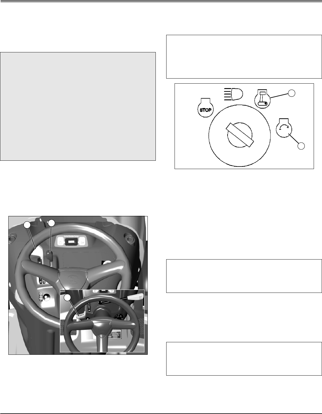
Using the Service Reminder
NOTE: Service hours will continue to run and service
intervals will be wrong if key is not returned to STOP
position.
MX7697
•The service reminder (A) shows the number of hours
the engine has run and will indicate that service is
necessary for the engine (B) or the mower (C). Follow the
service timetable on the maintenance schedule located
under the seat and the SERVICE INTERVALS section.
•Turn the key to STOP position when not using the
machine. The hours will continue to increase if the key is
c CAUTION: Avoid injury! Rotating blades are
dangerous. Children or bystanders may be
injured by runover and rotating blades.
Before backing up, carefully check the area
around the machine.
c CAUTION: Avoid injury! Children or bystanders
may attempt to move or operate an unattended
machine.
Always lock the park brake and remove the key
before leaving the machine unattended.
B
A
A
BC
A
Operating - 18
OPERATING
left in the on or run position but, will automatically shut off
after two hours.
Starting the Engine
1. Sit in seat.
2. Disengage mower blades.
3. Lock the park brake.
4. Put transmission in neutral.
5. Check starting conditions:
MX10501; MX7697
•If engine is cold:
On Models 2048 and 2548, move throttle lever (A) to the
half-speed position and move choke lever (B) up to the
choke position.
On all other Models, move throttle/choke lever (C) up to
the choke position.
•If engine is warm: Move throttle lever to the half-
speed position.
M94336a
6. Turn key to start position (D) for no more than five
seconds.
7. Release key to run position (E) when engine starts and
on models 2048 and 2548, gradually move choke lever
down to the off position.
•If engine does not start, wait 10 seconds.
•Turn key to start position again for no longer than 5
seconds.
•Repeat procedure if necessary.
8. Let engine run at half-speed position for a couple of
minutes to warm-up before operating machine.
Idling Engine
c CAUTION: Avoid injury! Engine exhaust fumes
contain carbon monoxide and can cause
serious illness or death.
Move the vehicle to an outside area before
running the engine.
Do not run an engine in an enclosed area
without adequate ventilation.
•Connect a pipe extension to the engine
exhaust pipe to direct the exhaust fumes out of
the area.
•Allow fresh outside air into the work area to
clear the exhaust fumes out.
C
AB
IMPORTANT: Avoid damage! Starter may be
damaged if starter is operated for more than 20
seconds at a time:
•Wait two minutes before trying again if engine
does not start.
IMPORTANT: Avoid damage! Unnecessary engine
idling may cause engine damage. Excessive idling
can cause engine overheating, carbon build-up, and
poor performance.
IMPORTANT: Avoid damage! Unnecessary engine
idling may cause engine damage. Excessive idling
can cause engine overheating, carbon build-up, and
poor performance.
E
D
Operating - 19
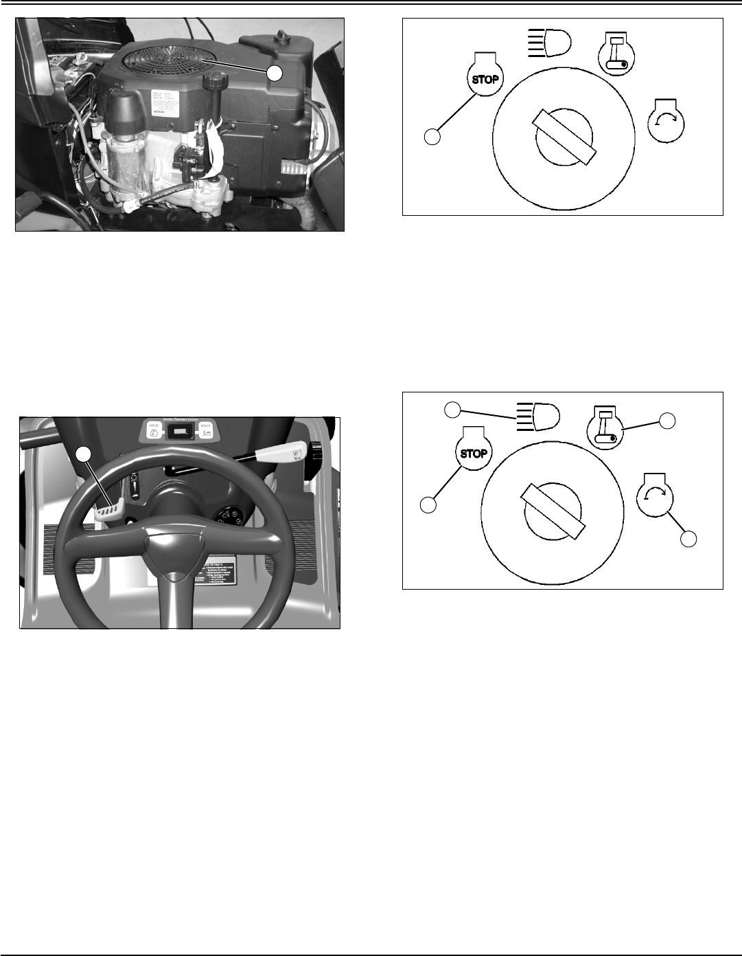
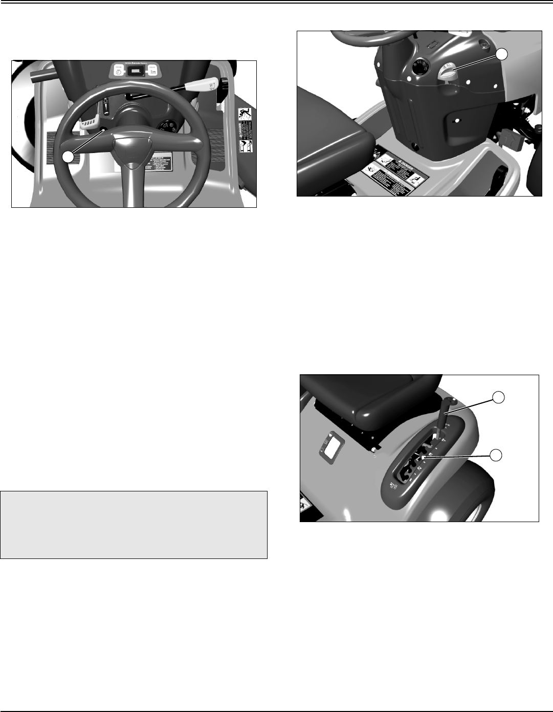
OPERATING
MX10526
Picture Note: Model 17.542 used for photo
purposes.
Engine is air cooled and needs a large volume of air to
keep cool. Keep air intake screen (A) on top of engine
clean.
Stopping the Engine
MX7697
Picture Note: Model 17.542 used for photo
purposes.
1. Move throttle lever (A) to slow position and let engine
run at low throttle a few seconds.
M94336a
2. Turn key to STOP position (B). Engine will stop and
headlights will turn off.
3. Remove key.
4. Lock the park brake.
Using Headlights
M94336a
A- STOP Position
B - Headlights On Position
C - Run Position
D - Start Position
Engine Off
NOTE: Headlights will drain the battery rapidly if key
switch is left in headlights on position (B) with the
engine off.
•To turn headlights on, turn key switch to headlights on
position (B).
•To turn headlights off, turn key switch to STOP position
(A).
Engine On
•To turn headlights on, start engine, then turn key switch
from run position (C) to headlights on position (B).
A
A
B
A
BC
D
Operating - 20
OPERATING
•To turn headlights off, turn key switch from headlights on
position (B) to run position (C).
Using Travel Controls on Gear Transmission
Travel Forward
MX7694
1. Push brake/clutch pedal (A) all the way down to stop
machine.
MX10502
2. Move transmission shift lever (B) to desired travel
speed.
3. Release brake/clutch pedal slowly.
Travel in Reverse
MX7697
1. Push brake/clutch pedal (A) all the way down.
NOTE: Any operating attachment and the engine will
stop as the gear shift lever is moved to R (reverse) with
attachment engaged.
2. Pull PTO lever (C) back to the off position to disengage
attachment.
3. Look behind the machine to be sure there are no
bystanders nearby.
MX10503
4. Move shift lever (B) to R (reverse) position.
5. Release brake/clutch pedal slowly.
Emergency Stopping
Push down brake/clutch pedal.
c CAUTION: Avoid injury! Children or bystanders
may be injured by runover and rotating blades.
Before traveling forward or rearward:
•Carefully check the area around the
machine.
•Disengage the mower before backing up.
IMPORTANT: Avoid damage! Stop machine
movement before shifting between reverse and
forward to prevent transmission damage.
A
B
A
C
B
Operating - 21
OPERATING
Using Travel Controls on Automatic
Transmission
Travel Forward
MX7696
•Push down the forward travel pedal (A).
Travel in Reverse
NOTE: Any operating attachment and the engine will
stop as the reverse foot pedal is depressed with
attachment engaged.
1. Disengage attachment:
MX7697
•On models with mechanical PTO, pull PTO lever (B)
back to the off position.
MX10501
•On models with electric PTO, push PTO switch (C)
down to the off position.
2. Look behind the machine to be sure there are no
bystanders nearby.
MX10530
3. Touch the reverse travel pedal (D) with front of foot and
slide foot over pedal from front to rear.
Emergency Stopping
•Push down brake pedal.
Using The Reverse Implement Option (RIO)
NOTE: Backing up while the mower is engaged is
strongly discouraged. The Reverse Implement Option
should be used only when operating another
attachment or when the operator deems it necessary to
reposition the machine with the mower engaged.
c CAUTION: Avoid injury! Children or bystanders
may be injured by runover and rotating blades.
Before traveling forward or rearward:
•Carefully check the area around the
machine.
•Disengage the mower before backing up.
A
B
c CAUTION: Avoid injury! Rotating blades are
dangerous. Children or bystanders may be
injured by runover and rotating blades.
Before backing up, carefully check the area
around the machine.
C
D
Operating - 22
OPERATING
1. Stop forward travel.
2. Look behind the machine to be sure there are no
bystanders.
MX7697
Picture Note: Model 17.542 shown.
3. Push and hold in the reverse implement switch (A) while
depressing reverse foot pedal slightly for automatic
transmission or moving the gear shift lever to the R
(reverse) position for gear transmission.
NOTE: If the engine and mower stop while
repositioning the machine, return the PTO lever/switch
to the off position. Start engine and engage mower.
Begin again with Step 2.
4. Release the reverse implement switch and reposition
the machine as the machine begins to move rearward.
5. Resume forward travel. The mower should continue
operating.
6. Repeat procedure to position the machine again.
Using Cruise Control (On Models 17.542, 2048
and 2548 Only)
Use cruise control when you want to maintain travel speed
without having to hold the forward travel pedal down.
Cruise control operates only for forward travel.
Engage Cruise Control
MX7696
1. Push forward pedal down until you reach desired travel
speed.
2. Pull lever (A) up and release forward pedal to lock the
cruise control.
Disengage Cruise Control
•Depress brake pedal, tap on forward pedal or push
cruise control lever down to the off position.
Using Mower Lift Lever
MX7695
Transporting or Getting On and Off Machine
•Pull lift lever (A) all the way back to transport position or
100 mm (4 in.) cutting height.
Mowing
•Push attachment lift lever (A) forward into the slot
adjacent to the desired cutting height.
•Slide the mower deck height reminder tab (B) to the
desired cutting height for the next time you mow.
c CAUTION: Avoid injury! Do not use cruise
control when going down hills. Machine speed
will increase. Operate machine in a large, open
area to learn how the cruise control works.
A
A
A
B
Operating - 23
OPERATING
Using Mower
1. Start engine and run at half speed for a couple of
minutes to warm up.
2. Lower mower to desired cutting height position.
3. Engage mower.
MX10501; MX7697
•On models with electric PTO: Pull PTO switch (A) up.
•On models with mechanical PTO: Push PTO lever
(B) forward.
4. Push throttle lever (C) up to the full throttle position.
NOTE: The mower and engine will stop as the reverse
foot pedal is depressed for Automatic Transmission or
when the gear shift lever is moved to the R (reverse)
position for Gear Transmission with mower engaged.
5. Disengage mower blades before moving in reverse.
•Tractors with mechanical PTO: Pull PTO lever back.
•Tractors with electric PTO: Push PTO switch down.
Pushing Machine
1. Unlock the park brake.
2. Put transmission in N (neutral).
MX7691
3. On Automatic Models: Pull out on free-wheeling lever
(A).
4. Push machine to desired location.
5. On Automatic Models: Push free-wheeling lever back in.
c CAUTION: Avoid injury! Stay clear of rotating
drivelines:
• Entanglement in rotating driveline can
cause serious injury or death.
• Wear close fitting clothing.
• Stop the engine and be sure PTO driveline
is stopped before getting near it.
• Make sure that all shields are installed and
used properly.
A
C
B
c CAUTION: Avoid injury! With the free-wheeling
valve open, the machine will have unrestricted
motion.
•The machine may free-wheel out of control if
the free-wheeling valve is opened with the
machine on an incline.
•Park the machine on a level surface before
opening the free-wheeling valve.
IMPORTANT: Avoid damage! Transmission damage
may occur if the machine is towed or moved
incorrectly:
•Move unit by hand only.
•Do not use another vehicle to move unit.
•Do not tow unit.
IMPORTANT: Avoid damage! The transmission
might be damaged if the free-wheeling lever is not
pushed back in completely before attempting to
start the engine. Do not start or operate the machine
with the free-wheeling lever pulled out.
A
Operating - 24
OPERATING
Unplugging Mower or Optional Bagger
Before getting off the seat:
1. Stop machine.
2. Disengage mower blades.
3. Move throttle lever to slow position.
4. Lower mower to the ground.
5. Lock the park brake.
6. Stop the engine.
7. Remove the key.
8. Wait for all moving parts to stop.
Transporting Machine on Trailer
Be sure trailer has all the necessary lights and signs
required by law.
1. Park trailer on level surface.
2. Drive machine onto heavy-duty trailer.
3. Lower mower to trailer deck.
4. Lock park brake.
5. Turn off machine and remove key.
6. Fasten lawn tractor to trailer with heavy-duty straps,
chains, or cables. Both front and rear straps must be
directed down and outward from tractor.
7. Strap down hood.
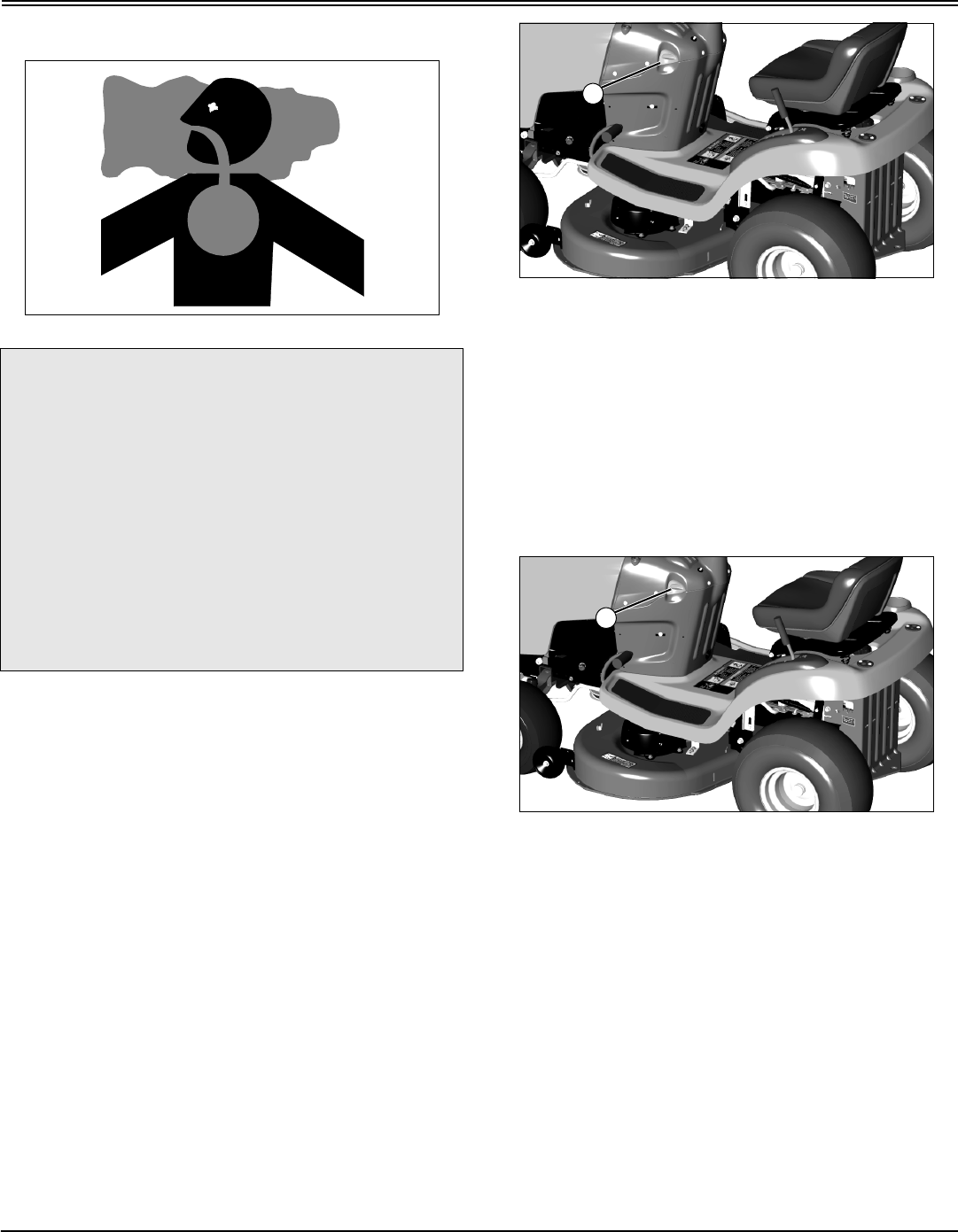
Using Mulch Cover
Side Discharge
1. Disconnect hooks from slot and/or wheel brackets and
remove mulch cover when side discharge is preferred.
2. Make sure the correct blades are installed for maximum
side discharge operation.
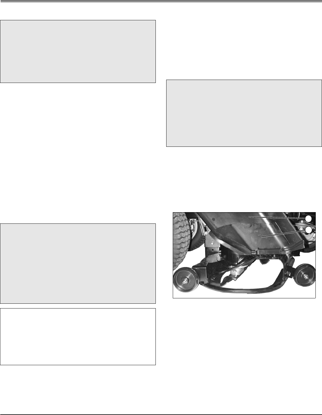
Mulching
MX10441
Picture Note: 48 (3 in 1) used for illustration.
1. Raise discharge chute (A) and metal deflector (B).
c CAUTION: Avoid injury! Rotating blades are
dangerous:
•Park the machine safely and lock the park
brake before getting off the seat.
•Turn the mower off.
•Stop the engine.
c CAUTION: Avoid injury! Use extra care when
loading or unloading the machine onto a trailer
or truck.
•Park trailer on a level surface.
•Use of a trailer with sides is recommended.
•Keep wheels away from drop-offs and
edges.
•Back slowly and in a straight line.
IMPORTANT: Avoid damage! Transmission damage
may occur if the machine is towed or moved
incorrectly:
•Move unit by hand only.
•Do not use another vehicle to move unit.
•Do not tow unit.
c CAUTION: Avoid injury! Rotating blades are
dangerous. Before adjusting or servicing
mower:
•Disconnect spark plug wire(s) to prevent
engine from starting accidently.
•Always wear gloves when handling mower
blades or working near blades.
A
B
Operating - 25
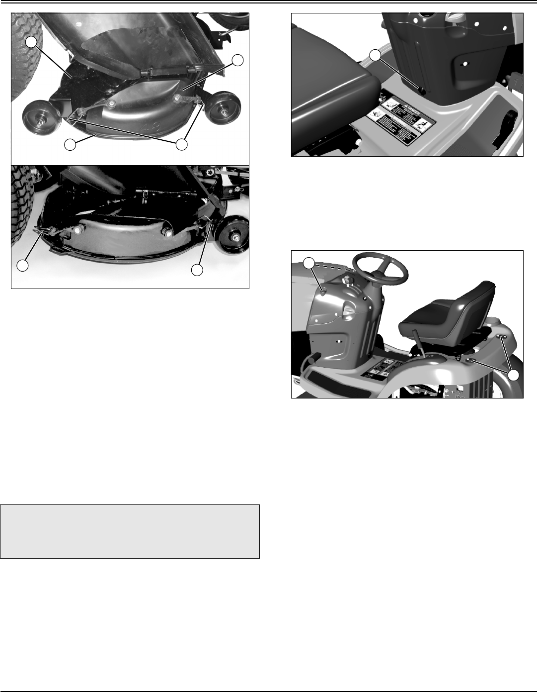
OPERATING
MX10440; MX8868
2. Install mulch cover (C) onto mower deck (D). Mulch
cover lip (E) must be seated in mower deck groove.
3. Hook mulch cover to mower deck:
•48 (3 in 1), wheel bracket grooves (F).
•42 (3 in 1), slot (G) on left side and wheel bracket
hole (H).
4. Lower discharge chute and metal deflector.
5. Make sure the correct blades are installed for maximum
mulching operation.
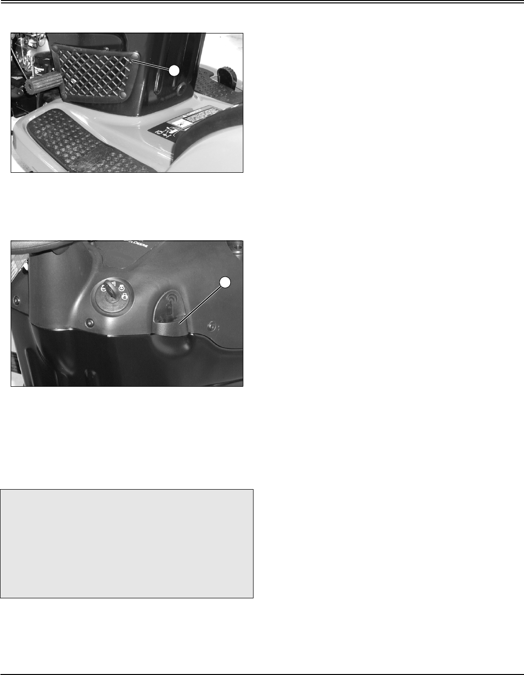
Using the Power Port (Models 2048 and 2548
Only)
MX7696
An electric power port (A) can be used for accessories. See
your Authorized Service Center.
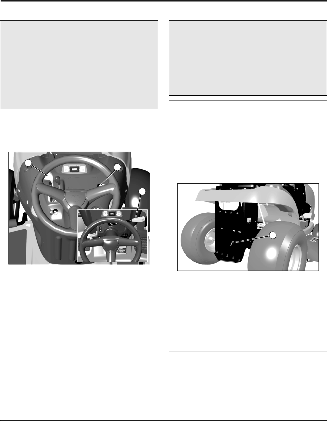
Using CargO Mount System™
MX7694
A - Front and Rear CargO Mount System™
The front and rear CargO Mount System™ brackets (A)
can be used for easy attachment of selected optional
equipment.
Use John Deere approved optional equipment only. See
your Authorized Service Center for approved optional
equipment.
c CAUTION: Avoid injury! Safe operation requires
your full attention. Do not wear radio or music
headphones while operating machine.
EF
D
C
H
G
A
A
A
Operating - 26
OPERATING
Using Storage Accessories
MX10524
A - Glove Storage Pocket
•Use the storage pocket (A) for small items such as
gloves.
MX10528
•On Models Without Cruise Control: Use the storage
retainer (B) to hold an electronic device such as garage
door opener.
Using Weights
NOTE: See your Authorized Service Center for
recommended weights.
•Install front weights for added stability and steering
control when you use equipment such as the rear-mounted
grass bagger.
•Install rear weights when using the snow blade or
snowblower.
•Remove weights when not required.
Using Tire Chains
Tire chains are recommended for use with snowblower and
snow blade.
See your Authorized Service Center for tire chains.
Mowing Tips
The following recommendations will produce the best lawn
cut quality and appearance:
•Keep mower blades sharp. Dull blades will tear grass;
tips of grass will then turn brown.
•Cutting grass too short may kill grass and let weeds
grow easily.
•Adjust cutting height to remove only 1/3 of the grass at a
time.
•Mow grass often. Short grass clippings will decay
quickly.
•Mow with engine at full throttle.
•Adjust travel speed to match mowing conditions:
•Travel at slow speed when you mow thick, tall grass,
make sharp turns, trim around objects, or when
mulching.
•Travel at moderate speed when you mow thin grass.
•Use a different mowing pattern each time you mow.
Overlap mowing paths 50 to 100 mm (2 to 4 in).
•Drive over ridges and through shallow ditches straight-
on, not at an angle.
•A thick layer of mulched leaves can prevent sunlight
from getting to grass and smother it. Taller grass heights
allow mulched leaves to dispense easier in lawn. Mulch
leaves several times if needed.
•Use a thatcher in late spring or summer to pull up dead
grass and aerate ground.
c CAUTION: Avoid injury! The machine may
become unstable when operating on slopes
and/or with some attachments.
Use front weights or rear weights to improve
stability when operating on slopes or using
attachments.
Remove weights when not required.
A
B

Replacement Parts - 27
REPLACEMENT PARTS
Replacement Parts
Service Literature
If you would like a copy of the Parts Catalog or Technical
Manual for this machine call:
•U.S. & Canada: 1-800-522-7448.
•All Other Regions: Your John Deere dealer.
Parts
We recommend John Deere quality parts and lubricants,
available at your John Deere dealer.
Part numbers may change, use part numbers listed below
when you order. If a number changes, your dealer will have
the latest number.
When you order parts, your John Deere dealer needs your
machine serial number and engine serial number. These
are the numbers that you recorded in the Product
Identification section of this manual.
Part Numbers
(Part numbers are subject to change without notice. Part
Numbers may be different outside the U.S.A.)
ITEM PART NUMBER
Home Maintenance Kit:
•1742
•17.542
•2048 & 2548
LG241
LG242
LG243
Air Cleaner Element (Foam):
•17 hp
•17.5 hp
•20 & 25 hp
LG274874
M131303
LG273638S
Air Cleaner Element (Paper):
•17 hp
•17.5 hp
•20 & 25 hp
LG695547
M145944
LG499486S
Fuel Filter:
•17 hp
•17.5 hp
•20 & 25 hp
LG394358
AM107314
LG691035
Oil Filter:
•17 hp
•17.5 hp
•20 & 25 hp
N/A
AM125424
LG492932S
Battery AM123101
Spark Plug M78543 (Champion
RC12YC)
Headlight Bulb AD2062R
Belts, Mower Drive:
•42 (3 in 1) Deck
•48 (3 in1) Deck
GX20072
GX20305
Blades, 42 (3 in1) Deck:
•Standard
•Bagging
GX20249
GX20433
Blades, 48 (3 in1) Deck:
•Standard
•Bagging
•Mulching
GX20250
GX20434
GX20819
ITEM PART NUMBER

Service Intervals - 28
SERVICE INTERVALS
Service Intervals
Servicing Your Machine
Please use the following timetables and the maintenance
schedule located under the seat to perform routine
maintenance on your machine.
Intervals
Before Each Use
•Check fuel level.
•Check engine oil level.
•Clean air intake screen.
•Check safety systems.
•Check tire pressure.
•Check/tighten loose hardware.
After First 5 Hours
•Change engine oil.
•On 42 (3 in 1): Check and adjust mower deck belt
tension.
•On 42 (3 in 1): Check and adjust mower deck spindle
brakes.
•Lubricate front axle pivot.
•Lubricate front wheel spindles and wheel bearings.
Every 25 Hours
•Change engine oil. (Service more frequently under
dusty conditions).
•Replace oil filter.
•Check/clean battery.
•Clean/replace air cleaner element and precleaner.
(Service more frequently under dusty conditions).
•Clean engine cooling fins.
•Replace fuel filter.
•Replace spark plug.
•Sharpen/replace blades.
•Clean mower deck.
•Level mower deck.
•On 42 (3 in 1): Check and adjust mower deck belt
tension.
•On 42 (3 in 1): Check and adjust mower deck spindle
brakes.
•Lubricate front axle pivot.
•Lubricate front wheel spindles and wheel bearings.
Every 50 Hours
•Lubricate pivot points and seat with general all-purpose
spray lubricant. (See Lubricating Pivot Points and
Lubricating Seat in the SERVICE LUBRICATION section.)
Every 100 Hours
•Replace mower drive belt.
•Sharpen/replace blades.
Before Storage
•Change engine oil.
•Replace oil filter.
•Check/clean battery.
•Charge battery.
•Clean/replace air cleaner precleaner.
•Check/replace air cleaner element.
•Clean air intake screen.
•Clean engine cooling fins.
•Replace fuel filter.
•Replace spark plug.
•Add fuel stabilizer.
•Sharpen/replace blades.
•Clean mower deck.
•Level mower deck.
•On 42 (3 in 1): Check and adjust mower deck belt
tension.
•On 42 (3 in 1): Check and adjust mower deck spindle
brakes.
•Check safety systems.
•Check/tighten loose hardware.
•Check tire pressure.
•Lubricate front axle pivot.
•Lubricate front wheel spindles and wheel bearings.
•Lubricate pivot points and seat with general all-purpose
spray lubricant. (See Lubricating Pivot Points and
IMPORTANT: Avoid damage! Operating in extreme
conditions may require more frequent service
intervals:
•Engine components may become dirty or
plugged when operating in extreme heat, dust or
other severe conditions.
•Engine oil and spark plugs may lose efficiency if
machine is operated constantly at slow or low
engine speeds or with frequent short trips.

Service Intervals - 29
SERVICE INTERVALS
Lubricating Seat in the SERVICE LUBRICATION section.)
After Storage
•Charge battery.
•Check safety systems.
•Check/tighten loose hardware.
•Check tire pressure.
Service Lubrication - 30
SERVICE LUBRICATION
Service Lubrication
Grease
The following greases are preferred:
•John Deere Multi-Purpose SD Polyurea Grease
•John Deere Multi-Purpose HD Lithium Complex Grease
•John Deere Moly High Temperature EP Grease
If not using any of the preferred greases, be sure to use a
general all-purpose grease with an NLGI grade No.2 rating.
Wet or high speed conditions may require use of a special-
use grease. Contact your Servicing dealer for information.
Lubricating Front Axle Pivot
MX10500
•Lubricate front axle center pivot (A) with one or two
shots of general all-purpose grease.
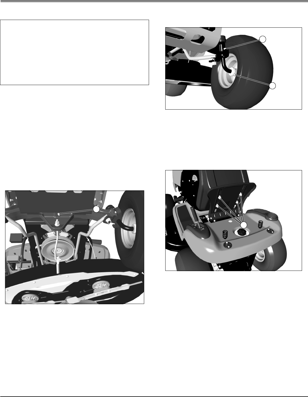
Lubricating Front Axle Wheel Spindles and
Bearings
MX7700
•Lubricate front wheel spindles (A) and bearings (B), one
on each side, with one or two shots of general all-purpose
grease.
Lubricating Seat
MX7699
•Lubricate plastic washers and bushings (A) under the
seat with a general all-purpose spray lubricant.
IMPORTANT: Avoid damage! Use recommended
John Deere greases to avoid component failure and
premature wear.
The recommended John Deere greases are effective
within an average air temperature range of -29 to 135
degrees C (-20 to 275 degrees F).
If operating outside that temperature range, contact
your Servicing dealer for a special-use grease.
A
A
B
A
Service Lubrication - 31
SERVICE LUBRICATION
Lubricating Pivot Points
MX10515
Picture Note: 42 (3 in 1) used for illustration.
A - Lift Pivots
B - Mower Deck Pivot Points (on both sides)
MX10512
Picture Note: 42 (3 in 1) used for illustration.
A - Blade Brake Pivots (42 (3 in 1) only)
B - Deck Idler Pivot
•Lubricate these pivot points with a general all-purpose
spray lubricant.
A
B
A
B
Service Engine - 32
SERVICE ENGINE
Service Engine
Engine Warranty Maintenance Statement
Maintenance, repair, or replacement of the emission control
devices and systems on this engine, which are being done
at the customers expense, may be performed by any non-
road engine repair establishment or individual. Warranty
repairs must be performed by an authorized John Deere
dealer.
Avoid Fumes
Engine Oil
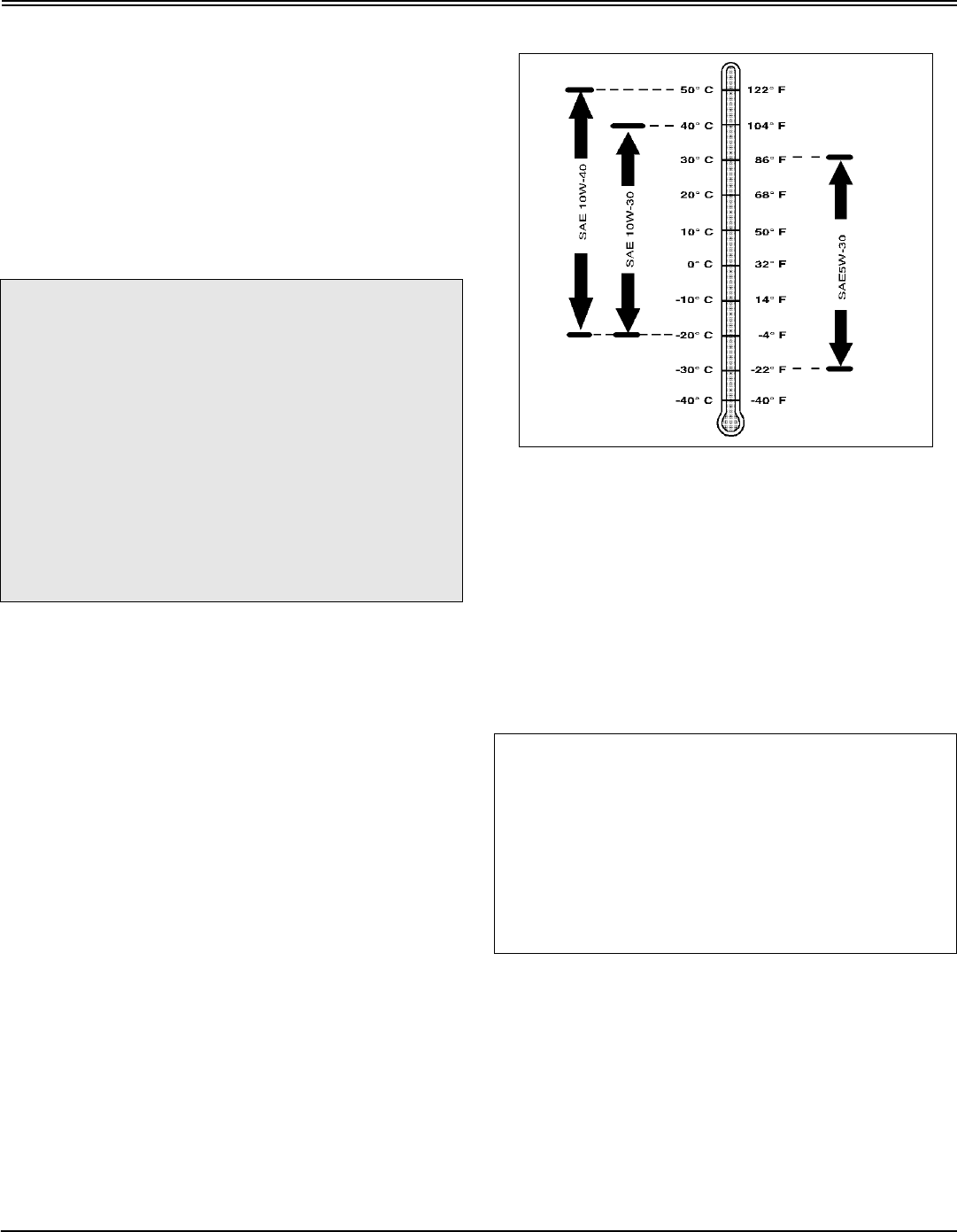
Use oil viscosity based on the expected air temperature
range during the period between oil changes.
The following John Deere oils are preferred:
MX4888
•TURF-GARD®
•PLUS-4®
Other oils may be used if above John Deere oils are not
available, provided they meet the following
specification:
•API Service Classification SG or higher
Checking Engine Oil Level
NOTE: Check oil twice a day if you run engine over 4
hours in a day.
Make sure engine is cold when checking engine oil
level.
1. Park machine safely. (See Parking Safely in the
SAFETY section.)
2. Lift hood.
3. Clean area around dipstick to prevent debris from falling
into crankcase.
c CAUTION: Avoid injury! Engine exhaust fumes
contain carbon monoxide and can cause
serious illness or death.
Move the vehicle to an outside area before
running the engine.
Do not run an engine in an enclosed area
without adequate ventilation.
•Connect a pipe extension to the engine
exhaust pipe to direct the exhaust fumes out of
the area.
•Allow fresh outside air into the work area to
clear the exhaust fumes out.
IMPORTANT: Avoid damage! Failure to check the oil
level regularly could lead to serious engine
problems if oil level is low:
•Check oil level before operating.
•Check oil level when the engine is cold and not
running.
•Keep level between the FULL and the ADD marks.
•Shut off engine before adding oil.
Service Engine - 33
SERVICE ENGINE
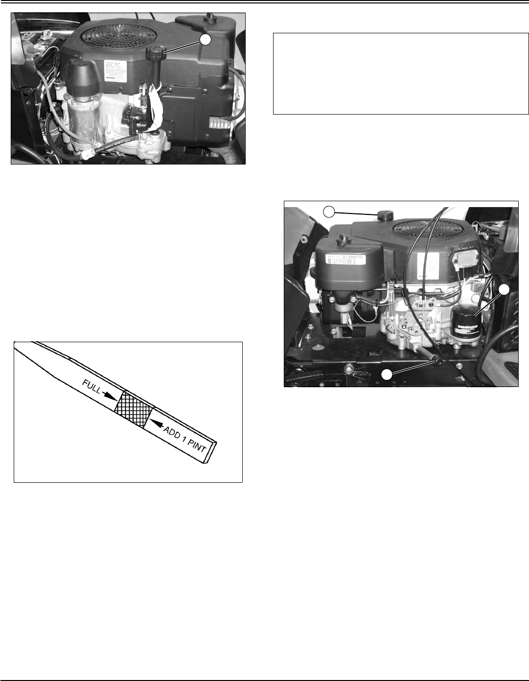
MX10526
Picture Note: Model 17.542 used for photo
purposes.
4. Remove dipstick (A). Wipe with clean cloth.
5. Install dipstick.
•Briggs and Stratton Engines: Install and tighten
dipstick.
•Kohler Engines: Install dipstick in tube, but do not
tighten it. Let dipstick threads rest on top of tube, turn
cap counterclockwise until it “clicks” or starts to engage
threads.
6. Remove dipstick.
M88476
7. Check oil level on dipstick. Oil must be between ADD
and FULL marks.
8. If oil level is low, add oil to bring oil level no higher than
FULL mark on dipstick. Do not overfill.
9. Install and tighten dipstick. Lower hood.
Changing Engine Oil and Filter
1. Run engine to warm oil.
2. Park machine safely. (See Parking Safely in the
SAFETY section.)
3. Lift hood.
4. Put drain pan under drain valve.
MX10525
Picture Note: Model 17.542 used for photo
purposes.
5. Rotate and remove drain cap (B) and drain oil into oil
drain pan. Allow oil to drain completely.
6. Remove dipstick (A).
7. Replace oil filter (C), if equipped.
a. Wipe dirt from around oil filter (C).
b. Place a drain pan or funnel under filter tray.
c. Remove old filter and wipe off filter tray.
d. Put a light coat of fresh, clean oil on the filter gasket.
e. Install replacement oil filter by turning oil filter to the
right (clockwise) until the rubber gasket contacts filter
base. Tighten filter an additional one-half turn.
8. Install drain cap.
9. Add oil no higher than FULL mark on dipstick. Use
approximately the amount of oil listed below. Do not overfill.
10.Install dipstick.
A
IMPORTANT: Avoid damage! Change the oil more
often if the vehicle is used in extreme conditions:
•Extremely dusty conditions.
•Frequent slow or low-speed operation.
•Frequent short trips.
A
B
C
Service Engine - 34
SERVICE ENGINE
11.Start and run engine at idle to check for leaks. Stop
engine. Fix any leaks before operating.
12.Check oil level, add oil if necessary.
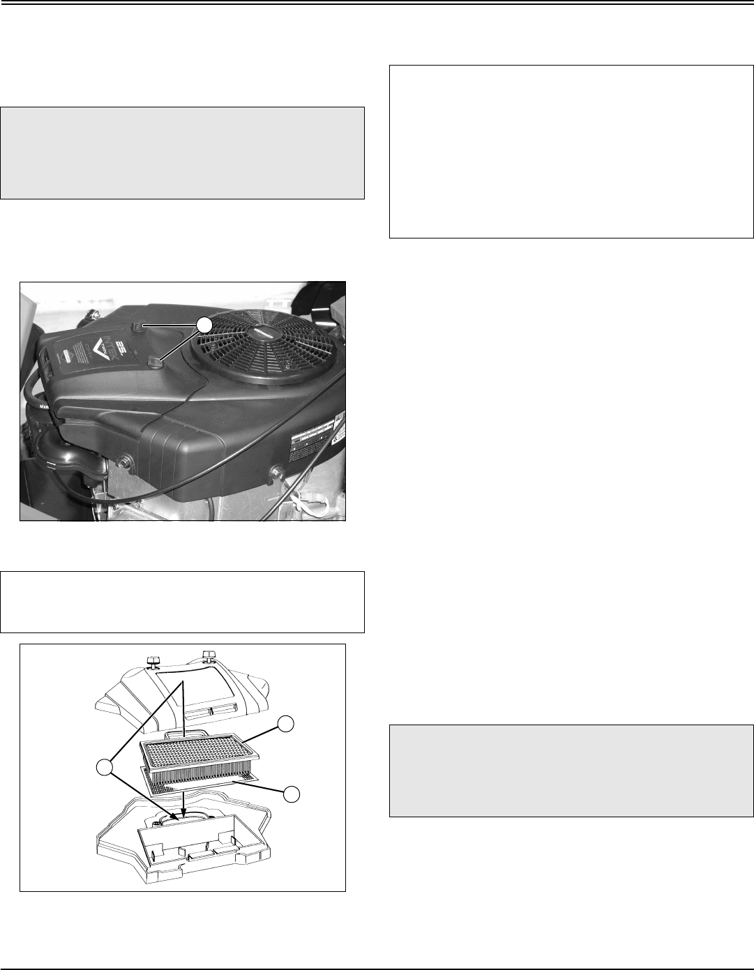
Cleaning Air Intake Screen and Engine Fins
1. Park machine safely. (See Parking Safely in the
SAFETY section.)
2. Lift hood.
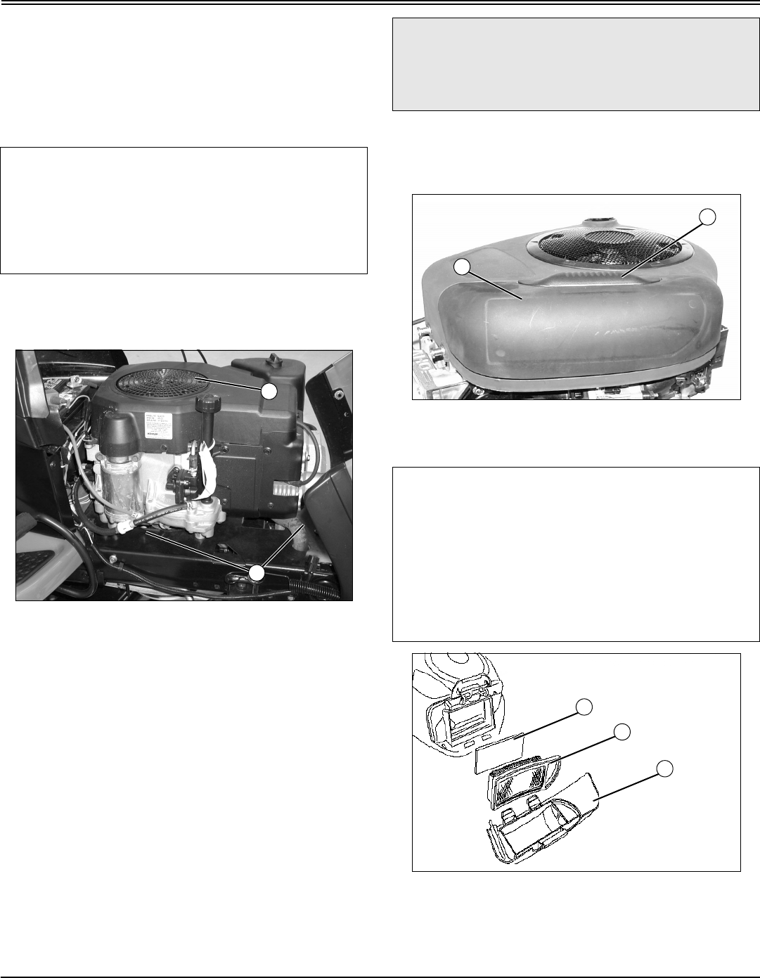
MX10526
Picture Note: Model 17.542 used for photo
purposes.
3. Clean air intake screen (A), cooling fins and external
surfaces (B), with rag, brush, vacuum or compressed air.
4. Lower hood.
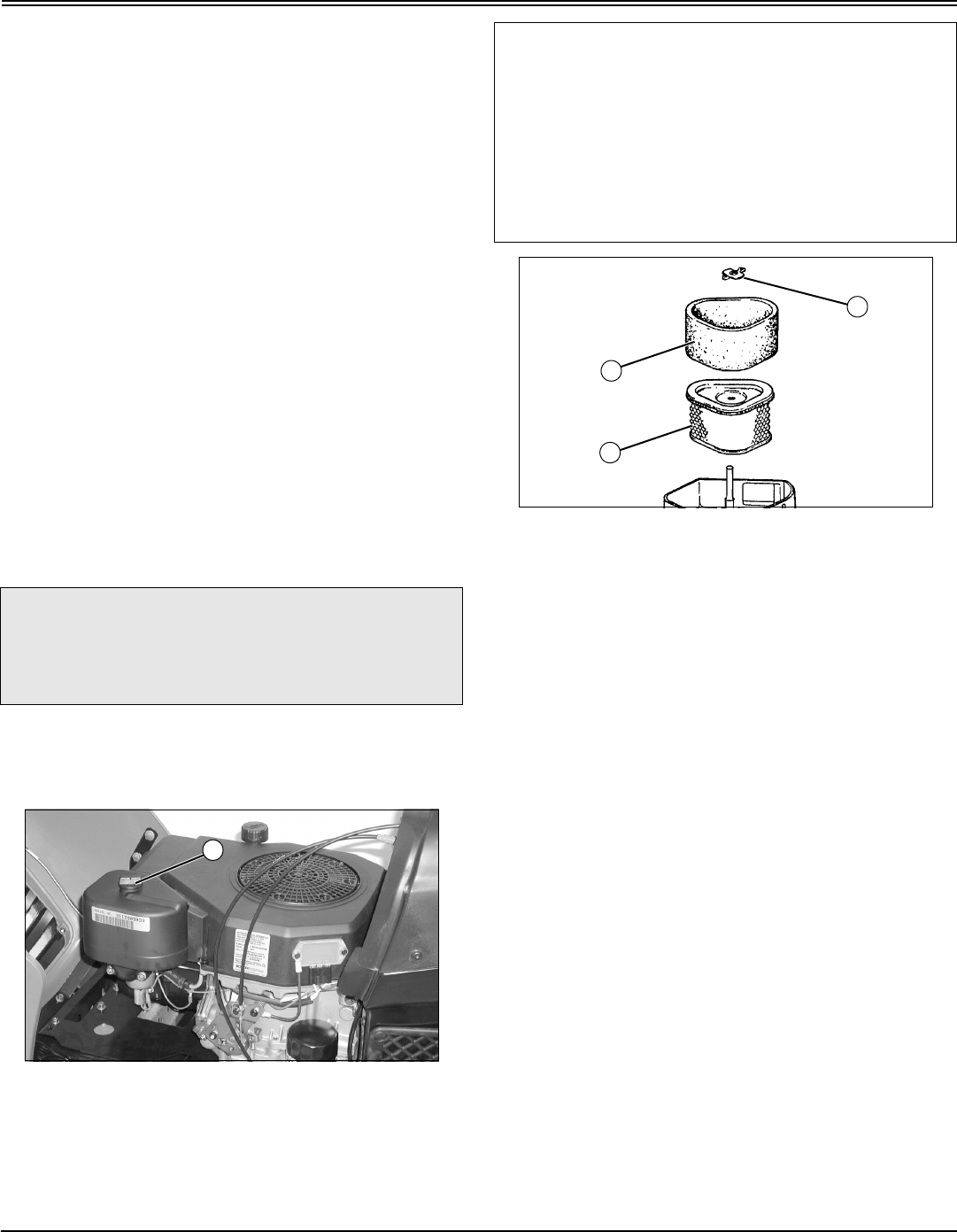
Checking and Cleaning Air Cleaner Elements
(Model 1742)
1. Park machine safely. (See Parking Safely in the
SAFETY section.)
2. Let engine cool.
3. Lift hood.
4. Clean dirt and debris from the air cleaner cover.
MX7680
5. Lift latch (A) to unlock cover (B). Lift cover forward and
remove.
MX7679
6. Inspect the foam precleaner (C) without removing it. If
the foam precleaner is dirty:
a. Remove it from the filter carefully, leaving the paper
IMPORTANT: Avoid damage! The engine is air-
cooled and requires a large amount of air intake
when running. Reduced air intake can cause
overheating:
•Keep air intake screen and cooling fins clean.
•Keep covers and screens in place.
A
B
c CAUTION: Avoid injury! Touching hot surfaces
can burn skin. The engine and components will
be hot if the engine has been running. Allow
the engine to cool before servicing.
IMPORTANT: Avoid damage! Dirt and debris can
enter the engine through a damaged filter element:
•Do not wash paper element.
•Do not attempt to clean paper element by tapping
against another object.
•Do not use pressurized air to clean element.
•Replace element only if it is very dirty, damaged
or the seal is cracked.
B
A
B
D
C
Service Engine - 35
SERVICE ENGINE
element (D) in the air cleaner housing.
b. Wash precleaner in a solution of warm water and
liquid detergent. Do not use oil.
c. Rinse precleaner thoroughly. Squeeze out excess
water in a dry cloth until precleaner is completely dry.
7. Inspect the paper filter element (D) without removing it.
If the paper filter element is damaged or dirty:
•Carefully remove the element from the air cleaner
housing.
8. Clean air cleaner base very carefully, preventing any dirt
from falling into carburetor.
9. Install new paper filter element.
10.Install foam precleaner on paper filter element.
11.Install air cleaner cover and push latch down to lock.
12.Lower hood.
Checking and Cleaning Air Cleaner Elements
(Model 17.542)
1. Park machine safely. (See Parking Safely in the
SAFETY section.)
2. Let engine cool.
3. Lift hood.
4. Clean dirt and debris from the air cleaner cover.
MX7687
5. Loosen knob (A) and remove cover.
MX8392
6. Inspect the foam precleaner (B) without removing it. If
the foam precleaner is dirty:
a. Remove it from the filter carefully, leaving the paper
element (C) in the air cleaner housing.
b. Wash precleaner in a solution of warm water and
liquid detergent.
c. Rinse precleaner thoroughly. Squeeze out excess
water in a dry cloth until precleaner is completely dry.
d. Put approximately 30 ml. (1 oz) of clean engine oil
onto the precleaner. Squeeze precleaner to distribute
the oil evenly. Squeeze out excess oil with a clean cloth.
7. Inspect the paper filter element (C) without removing it.
If the element is damaged or dirty:
a. Remove wing nut (D).
b. Carefully remove the element from the air cleaner
housing.
c. Clean air cleaner base very carefully, preventing any
dirt from falling into carburetor.
d. Install new paper filter element into air cleaner. Make
sure element is seated properly.
e. Install wing nut.
8. Install precleaner on paper element.
9. Install air cleaner cover. Do not overtighten.
10.Lower hood.
c CAUTION: Avoid injury! Touching hot surfaces
can burn skin. The engine and components will
be hot if the engine has been running. Allow
the engine to cool before servicing.
A
IMPORTANT: Avoid damage! Dirt and debris can
enter the engine through a damaged filter element:
•Do not wash paper element.
•Do not attempt to clean paper element by tapping
against another object.
•Do not use pressurized air to clean element.
•Replace element only if it is very dirty, damaged
or the seal is cracked.
D
B
C
Service Engine - 36
SERVICE ENGINE
Checking and Cleaning Air Cleaner Elements
(Models 2048 and 2548)
1. Park machine safely. (See Parking Safely in the
SAFETY section.)
2. Let engine cool.
3. Lift hood.
4. Clean dirt and debris from the air cleaner cover.
MX7682
5. Loosen knobs (A) and remove cover.
M96094
6. Do not drop anything into the carburetor air intake (B). If
anything falls into the carburetor air intake it must be
removed.
7. Lift out filter cartridge (C) and inspect it for damage.
8. Inspect the foam precleaner without removing it. If the
foam precleaner (D) is dirty:
a. Remove it from the filter carefully.
b. Wash precleaner in a solution of warm water and
liquid detergent.
c. Rinse precleaner thoroughly. Squeeze out excess
water in a dry cloth until precleaner is completely dry.
d. Put approximately 30 ml. (1 oz) of clean engine oil
onto the precleaner. Squeeze precleaner to distribute
the oil evenly. Squeeze out excess oil with a clean cloth.
9. Clean air cleaner housing carefully. Prevent any dirt
from falling into carburetor.
10.Install foam precleaner mesh side up.
11.Install cartridge. Make sure cartridge and seal are
properly seated and sealing the carburetor air intake area.
12.Install air cleaner cover and tighten knobs. Do not
overtighten.
13.Lower hood.
Checking Spark Plug
1. Park machine safely. (See Parking Safely in the Safety
Section.)
2. Let engine cool.
3. Lift hood.
c CAUTION: Avoid injury! Touching hot surfaces
can burn skin. The engine and components will
be hot if the engine has been running. Allow
the engine to cool before servicing.
IMPORTANT: Avoid damage! To prevent engine
damage, do not allow any foreign objects to fall into
the carburetor air intake.
A
C
D
B
IMPORTANT: Avoid damage! Dirt and debris can
enter the engine through a damaged filter element:
•Do not wash paper element.
•Do not attempt to clean paper element by tapping
against another object.
•Do not use pressurized air to clean element.
•Replace element only if it is very dirty, damaged
or the seal is cracked.
c CAUTION: Avoid injury! Touching hot surfaces
can burn skin. The engine and components will
be hot if the engine has been running. Allow
the engine to cool before servicing.
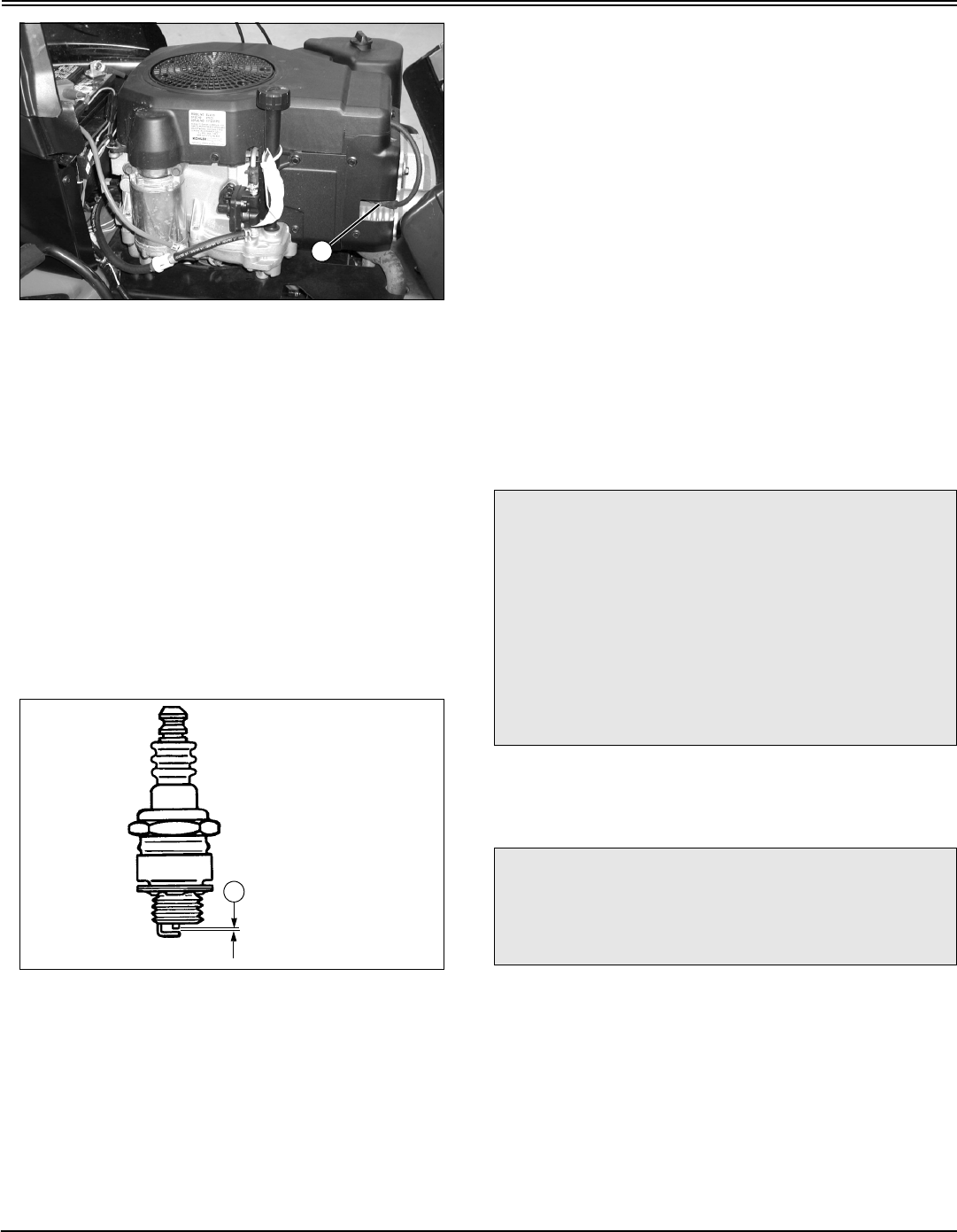
Service Engine - 37
SERVICE ENGINE
MX10526
Picture Note: Model 17.542 used for photo
purposes.
4. Disconnect spark plug wire(s) (A), one on each side on
V-twin engines.
5. Remove spark plug(s).
6. Clean spark plug carefully with a wire brush.
7. Inspect spark plug for:
•Cracked porcelain.
•Pitted or damaged electrodes.
•Other wear or damage.
NOTE: In Canada, replace spark plug with resistor plug
only.
8. Replace spark plug as necessary.
M85200
9. Check plug gap (B) with a wire feeler gauge. To change
gap, move the outer electrode.
•Gap must be 1 mm (0.040 in.).
10.Install and tighten spark plugs to 20 N•m (15 lb-ft).
11.Connect spark plug wires and lower hood.
Adjusting Carburetor
NOTE: Carburetor is calibrated by the engine
manufacturer and is not adjustable.
If engine is operated at altitudes above 1829 m (6,000
ft), some carburetors may require a special high
altitude main jet. See your John Deere dealer.
If engine is hard to start or runs rough, check the
troubleshooting section of this manual.
Possible engine surging will occur at high throttle with
transmission in “N” neutral and mower engagement lever
disengaged. This is a normal condition due to the emission
control system.
After performing the checks in the troubleshooting section
and your engine is still not performing correctly, contact
your John Deere dealer.
Replacing Fuel Filter
NOTE: Change filter when fuel is low.
1. Park machine safely. (See Parking Safely in the
SAFETY section.)
2. Let engine cool.
3. Lift hood.
4. Put a drain pan under fuel filter.
A
B
c CAUTION: Avoid injury! Fuel vapors are
explosive and flammable:
•Do not smoke while handling fuel.
•Keep fuel away from flames or sparks.
•Shut off engine before servicing.
•Cool engine before servicing.
•Work in a well-ventilated area.
•Clean up spilled fuel immediately.
c CAUTION: Avoid injury! Touching hot surfaces
can burn skin. The engine and components will
be hot if the engine has been running. Allow
the engine to cool before servicing.
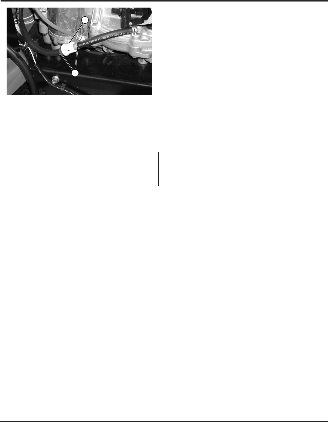
Service Engine - 38
SERVICE ENGINE
MX7685
Picture Note: Model 17.542 used for photo
purposes.
5. Slide hose clamps (A) away from fuel filter (B) using a
pliers.
6. Disconnect hoses from filter.
7. Connect hoses to new filter making sure the filter arrow
is pointed in the direction of the fuel flow.
8. Install clamps and check for leaks.
9. Lower hood.
IMPORTANT: Avoid damage! Incorrect installation of
fuel filter may cause engine damage. Install the filter
with the arrow pointing in the direction of fuel flow
for proper operation.
A
B

Service Transmission - 39
SERVICE TRANSMISSION
Service Transmission
Checking Transmission
The transmission is a sealed component. No maintenance
is required on this transmission. If you suspect any
transmission problems, please contact your Authorized
Service Center.
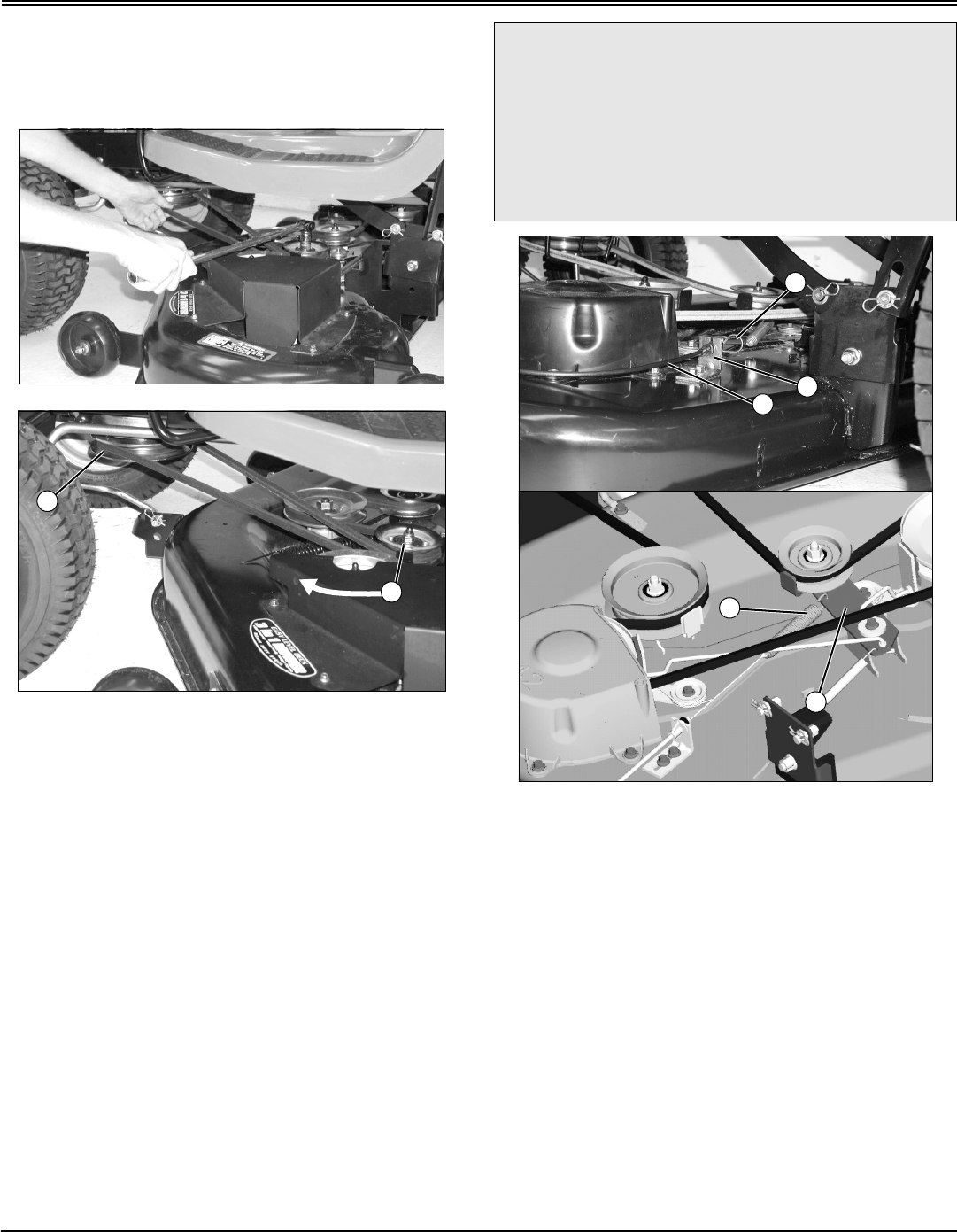
Service Mower - 40
SERVICE MOWER
Service Mower
Installing or Removing Mower Drive Belt at
Engine Drive Sheave (48 (3-in-1) Only)
NOTE: This procedure is for easy installing and
removing.
MX10523
MX10520
1. Put lift lever in lowest position.
2. Put a 15mm closed wrench or a socket on the idler
sheave nut (A), move idler sheave toward front of tractor
and hold to release belt tension.
3. Install the belt on the drive sheave (B).
4. Release idler sheave to tighten belt.
5. Use same procedure to remove belt.
Removing Mower
1. Park machine safely. (See Parking Safely in SAFETY
section.)
2. Put wood blocks under each side of mower deck.
3. Put lift lever in lowest position, bringing deck down onto
blocks.
MX10517; MX7681
Picture Note: 42 (3 in 1) only.
4. On machines with 42 (3 in 1), disconnect PTO drive
cable (A).
a. Remove spring locking pin (B), pull and hold PTO
drive cable out, lift up and remove from bracket (C).
b. Remove cable spring (D) from idler sheave bracket
(E).
B
A
c CAUTION: Avoid injury! Rotating blades are
dangerous. Before adjusting or servicing
mower:
•Disconnect spark plug wire(s) to prevent
engine from starting accidently.
•Always wear gloves when handling mower
blades or working near blades.
A
B
C
E
D
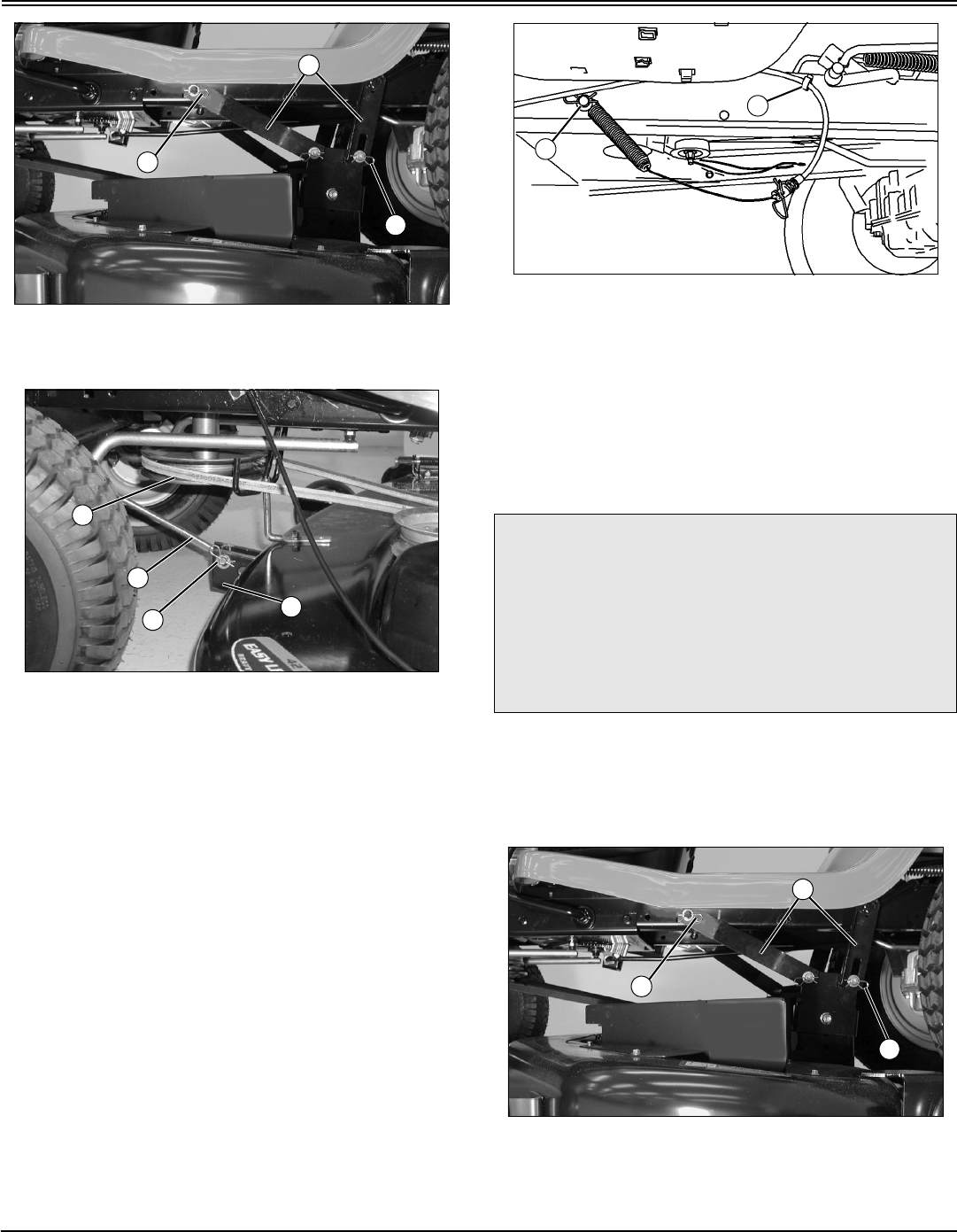
Service Mower - 41
SERVICE MOWER
MX10516
5. Remove spring locking pins and washers (F) and
disconnect rear draft arms (G), two on each side.
MX10521
Picture Note: 42 (3 in 1) shown.
6. Remove spring locking pin and washer (H) and front
draft rod (I) from mower deck bracket (J).
7. Remove mower drive belt from drive sheave (K).
8. Remove wood blocks from both sides and slide mower
out from under the machine.
9. When operating the machine without the mower deck:
•Remove rear draft arms and front draft rod from
tractor and attach them to the mower deck.
MX10514
•On 42 (3 in 1) only: Push PTO drive cable into clip (L)
and hook end of cable spring with hardware (M) into peg
on left side of machine frame.
Installing Mower
1. Park machine safely. (See Parking Safely in SAFETY
section.)
2. Put lift lever in the transport position.
3. Slide mower under machine.
4. Put wood blocks under each side of mower deck.
5. Put lift lever in lowest position.
MX10516
6. Fasten rear draft arms (A), two on each side, with
washers and spring locking pins (B).
F
F
G
I
J
H
K
c CAUTION: Avoid injury! Rotating blades are
dangerous. Before adjusting or servicing
mower:
•Disconnect spark plug wire(s) to prevent
engine from starting accidently.
•Always wear gloves when handling mower
blades or working near blades.
L
M
B
B
A
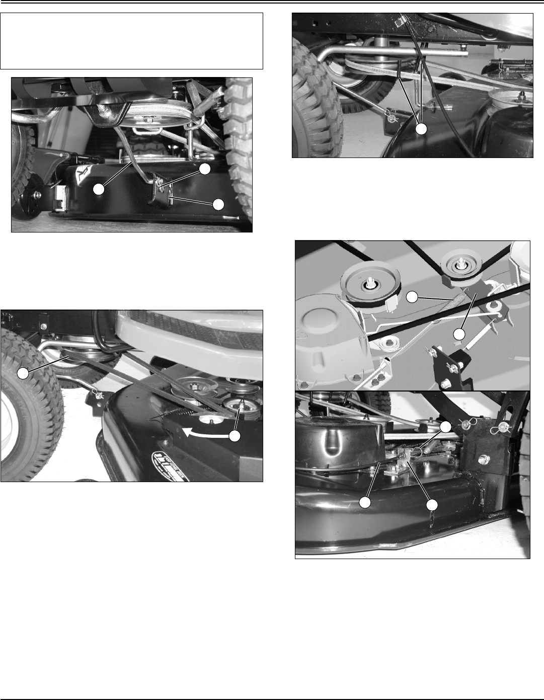
Service Mower - 42
SERVICE MOWER
MX10529
Picture Note: 42 (3 in 1) used for photo purposes.
7. Install front draft rod (C) into mower deck bracket (D)
and secure with washer and spring locking pin (E) on the
left side of bracket as shown.
MX10520
Picture Note: 48 (3 in 1) used for photo purposes.
8. Put mower drive belt on engine drive sheave (F).
•On 48 (3 in 1): Move idler sheave (G) and tensioning
arm toward front of tractor and hold while installing belt
on drive sheave.
MX10521
•On 42 (3 in 1): Make sure belt is routed through both
belt guides (H).
9. Remove wood blocks from both sides of mower deck.
10.On machines with 42 (3 in 1): Attach PTO drive cable.
MX7681; MX10517
Picture Note: 42 (3 in 1) only.
a. Route cable under mower belt and brake rod and
attach cable spring (I) to idler sheave bracket (J).
b. Pull out on cable (K), align black end of cable with
slot in bracket (L) and release cable into slot. Secure
with spring locking pin (M).
11.Level mower.
IMPORTANT: Avoid damage! To prevent clutch
damage, make sure front draft rod is installed
correctly. Secure rod with washer and spring locking
pin on the left side of mower deck bracket.
C
D
E
F
G
H
I
J
KL
M
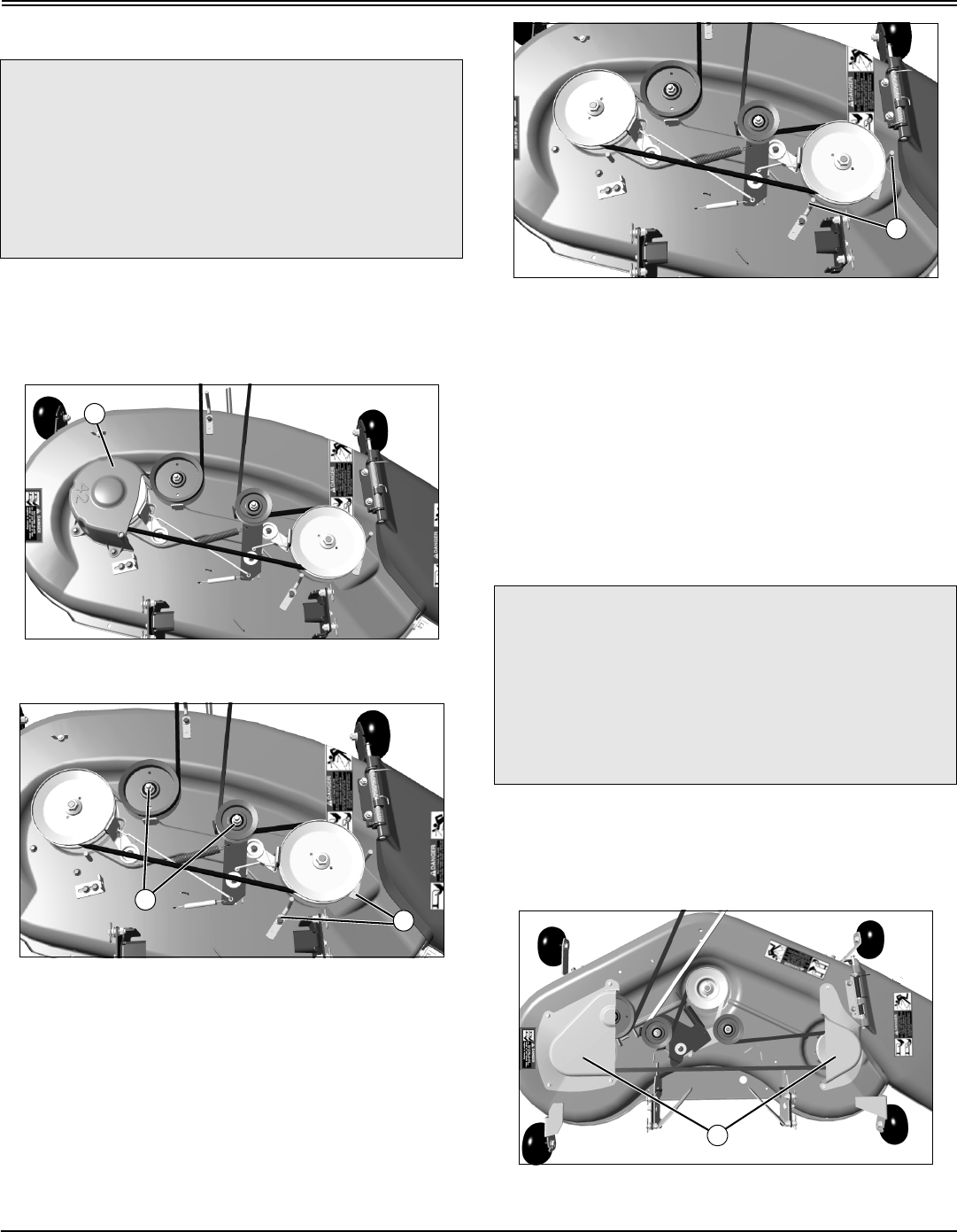
Service Mower - 43
SERVICE MOWER
Replacing Mower Drive Belt (42 (3 in 1))
1. Park machine safely. (See Parking Safely in SAFETY
section.)
2. Remove mower deck.
3. Remove drive belt.
MX10511
a. Remove three capscrews and belt shield (A).
b. Loosen sheaves (B) and belt guides (C).
c. Remove mower belt.
4. Inspect belt for wear or damage; replace as necessary.
5. Clean top surface of mower deck and sheaves.
MX10512
6. Install belt on mower deck as shown. Make sure belt is
in the groove of each sheave and inside belt guides (D).
7. Tighten sheaves to 47 N•m (35 lb-ft).
8. Install belt shield(s).
9. Install mower deck.
10.Adjust mower belt tension and spindle brakes, if
necessary.
Replacing Mower Drive Belt (48 (3 in 1))
1. Park machine safely. (See Parking Safely in SAFETY
section.)
2. Remove mower deck.
3. Remove drive belt.
MX10505
a. Remove seven capscrews and left and right belt
c CAUTION: Avoid injury! Rotating blades are
dangerous. Before adjusting or servicing
mower:
•Disconnect spark plug wire(s) to prevent
engine from starting accidently.
•Always wear gloves when handling mower
blades or working near blades.
A
B
C
c CAUTION: Avoid injury! Rotating blades are
dangerous. Before adjusting or servicing
mower:
•Disconnect spark plug wire(s) to prevent
engine from starting accidently.
•Always wear gloves when handling mower
blades or working near blades.
D
D
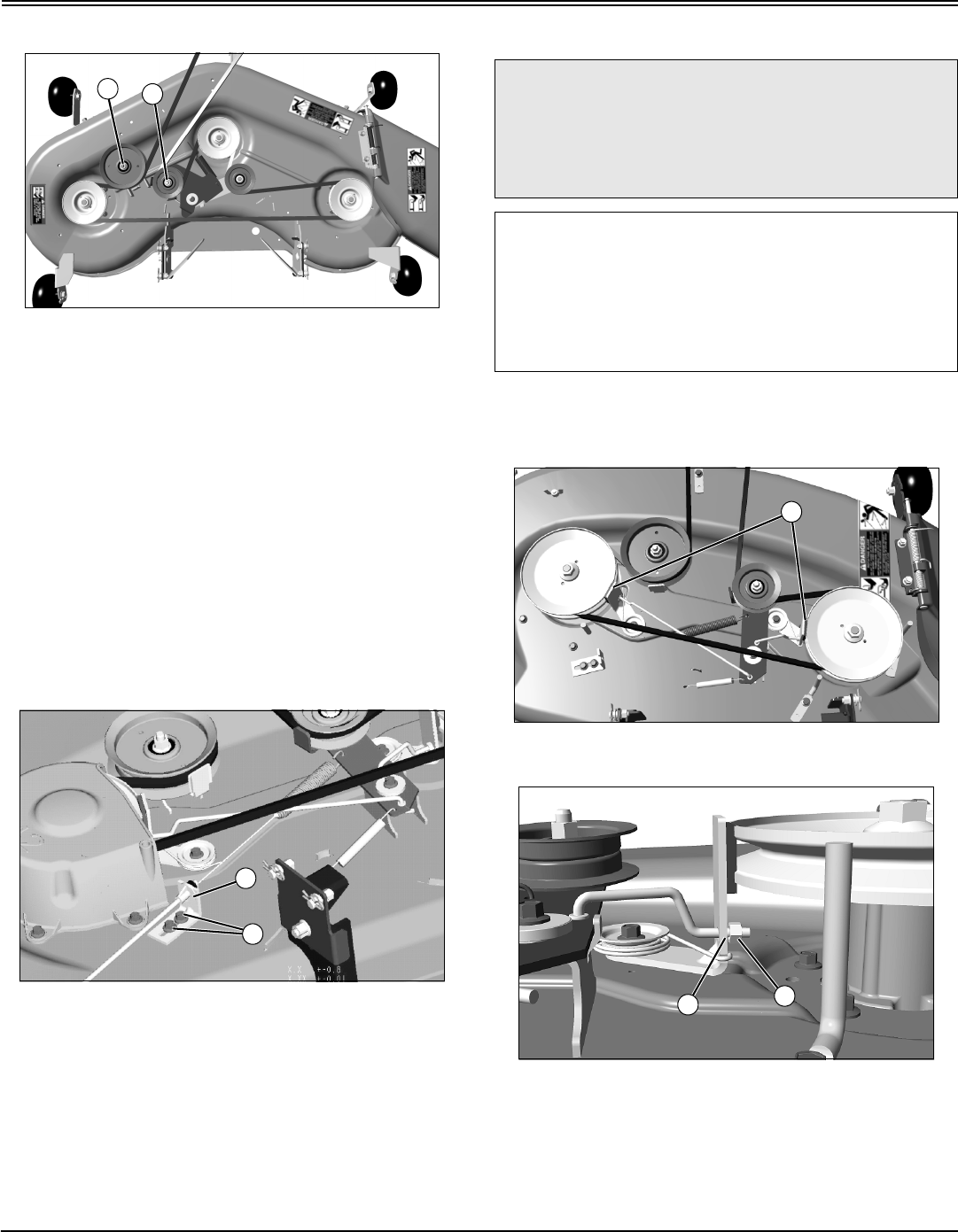
Service Mower - 44
SERVICE MOWER
shields (D).
MX10506
b. Loosen sheaves (E) and (F).
c. Remove mower belt.
4. Inspect belt for wear or damage; replace as necessary.
5. Clean top surface of mower deck and sheaves.
6. Install belt on mower deck as shown. Make sure belt is
in the groove of each sheave.
7. Tighten sheaves to 47 N•m (35 lb-ft).
8. Install belt shield(s).
9. Install mower deck.
Adjusting Mower Belt Tension (42 (3 in 1)
Only)
MX7681
1. Park machine safely. (See Parking Safely in the
SAFETY section.)
2. Loosen nuts (A) and move cable bracket (B) away from
the center of deck to tighten belt tension. Tighten nuts.
Adjusting Spindle Brakes (42 (3 in 1) Only)
1. Park machine safely. (See Parking Safely in the
SAFETY section.)
2. Remove mower deck.
MX10512
3. Remove left belt shield and adjust two blade brakes (A).
MX10507
4. Measure distance from spindle brake bracket (B) to nut
(C) on end of brake rod.
•Bracket to nut distance should be: 2 – 3 mm (0.08 –
0.12 in).
5. If adjustment is required, turn nut (C) on end of brake
EF
A
B
c CAUTION: Avoid injury! Rotating blades are
dangerous. Mower blades must stop within 5
seconds after mower is turned off. Check
spindle brake measurement every 25 hours or
once a year (whichever comes first).
IMPORTANT: Avoid damage! Avoid belt damage.
Spindle brake engagement should be checked and
corrected every time the mower belt tension is
adjusted.
Mower belt tension should be adjusted, if required,
before brakes are adjusted.
A
B
C
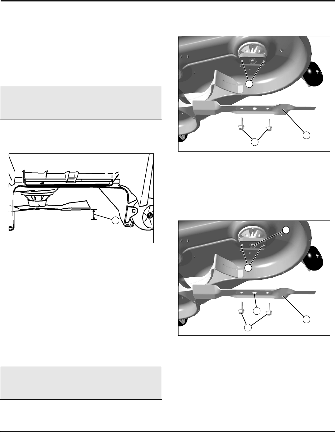
Service Mower - 45
SERVICE MOWER
rod in correct direction to set brake at proper distance from
pulley.
6. Adjust both brakes.
7. Install left belt shield.
8. Install mower deck.
Checking for Bent Mower Blades
1. Park machine safely. (See Parking Safely in the Safety
section.)
2. Raise mower to transport position to access blades.
MX4897
Picture Note: Mower deck with side discharge used
for illustration
3. Measure distance (A) between blade tip and flat ground
surface.
4. Rotate blade 180° and measure distance between other
blade tip and flat ground surface.
5. Install new blade if the difference between the two
measurements is more than 3 mm (1/8 in.).
6. Repeat for all blades.
Servicing Mower Blades
Removing Mower Blades
1. Raise mower deck to gain access to mower blades. If
necessary, remove mower deck.
2. Block mower blade with a piece of wood to prevent it
from spinning.
MX10510
3. Loosen and remove two cap screws (A) and blade (B).
Do not remove two nuts/bushings (C) inside holes of the
blade adapter.
4. Inspect blades; sharpen, balance or replace blades as
necessary.
Installing Mower Blades
MX10510
1. Make sure that two nuts/bushings (C) are in place.
2. Position mower blade (B) with the cutting edge towards
the ground.
3. Align the center hole (D) in the blade with the spindle
shaft (E) and put the blade onto the mower spindle.
4. Install and hand tighten cap screws (A) until mower
blade is in full contact (fully seated) with spindle.
5. Block mower blade with a piece of wood to prevent
spinning and tighten cap screws to 62 N•m (46 lb-ft).
c CAUTION: Avoid injury! Mower blades are
sharp. Always wear gloves when handling
mower blades or working near blades.
c CAUTION: Avoid injury! Mower blades are
sharp. Always wear gloves when handling
mower blades or working near blades.
A
B
A
C
B
D
E
A
C
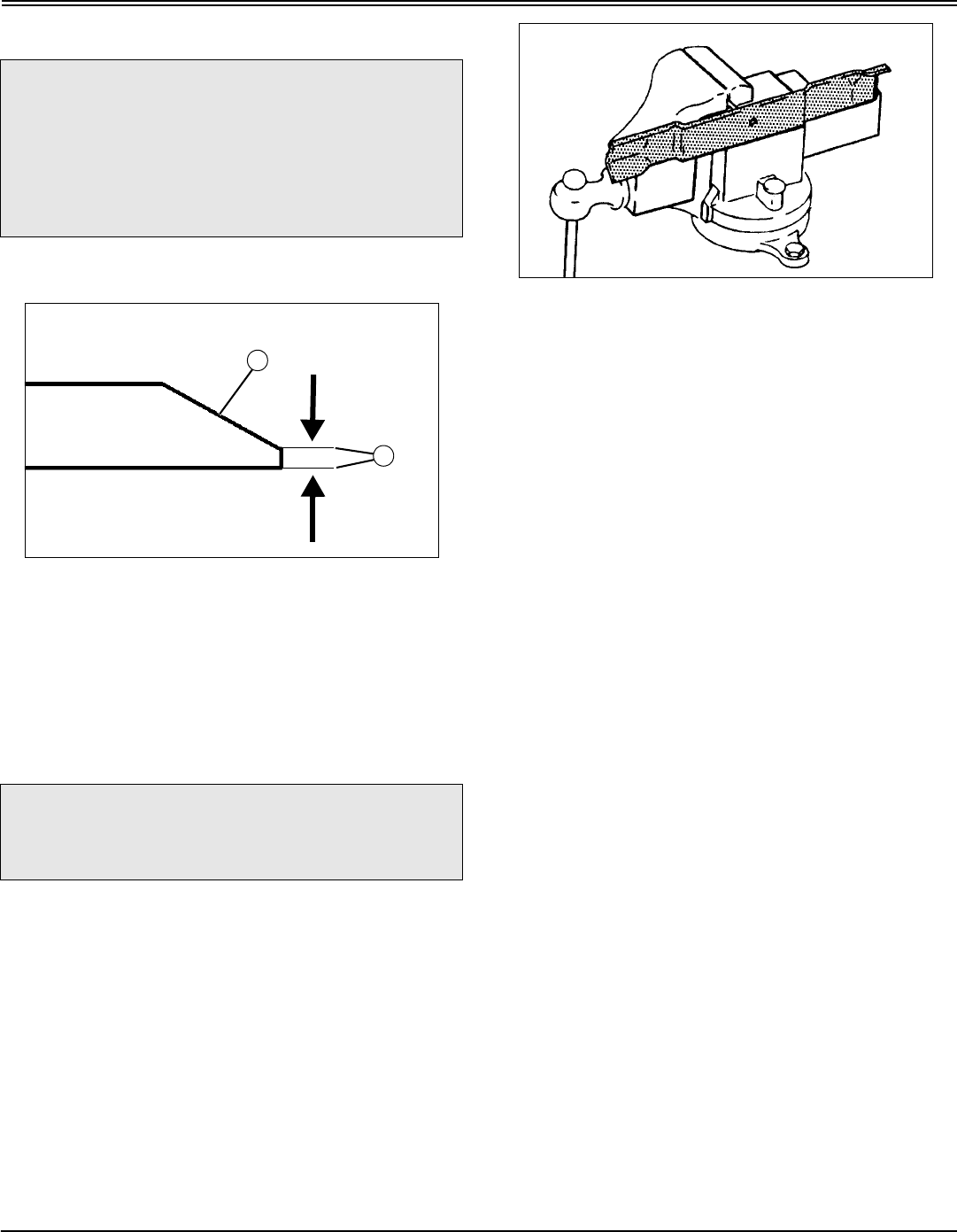
Service Mower - 46
SERVICE MOWER
Sharpening Blades
•Sharpen blades with grinder, hand file, or electric blade
sharpener.
MX8333
•Keep original bevel (A) when grinding.
•Blade should have 0.40 mm (1/64 in.) cutting edge (B)
or less.
•Balance blades before installing.
Balancing Blades
1. Clean blade.
M61524
2. Put blade on nail in a vise. Turn blade to horizontal
position.
3. Check balance. If blade is not balanced, heavy end of
blade will drop.
4. Grind bevel of heavy end. Do not change blade bevel.
c CAUTION: Avoid injury! Mower blades are
dangerous!
•Always wear gloves while working on
blades.
•Always wear safety eye protection when
grinding.
c CAUTION: Avoid injury! Mower blades are
sharp. Always wear gloves when handling
mower blades or working near blades.
A
B
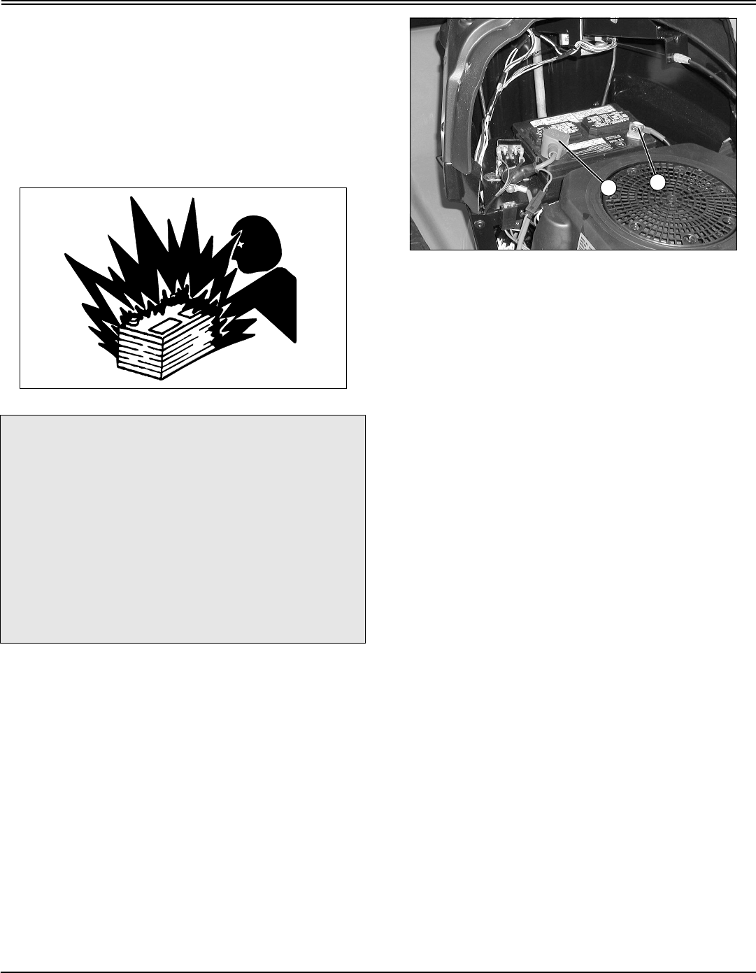
Service Electrical - 47
SERVICE ELECTRICAL
Service Electrical
WARNING: Battery posts, terminals and related
accessories contain lead and lead components, chemicals
known to the State of California to cause cancer and
reproductive harm. Wash hands after handling.
Service the Battery Safely
Removing and Installing the Battery
Removing
1. Park machine safely and lift hood. (See Parking Safely
in the SAFETY Section.)
MX7686
2. Disconnect negative (–) battery cable (A).
3. Push red cover (B) away from positive (+) battery
terminal and remove cable from battery.
4. Remove battery.
Installing
1. Place battery into battery tray.
2. Connect positive (+) cable to battery first, then negative
(-) cable.
3. Apply general purpose grease or silicone spray to
terminal to help prevent corrosion.
4. Slide red cover over positive battery terminal.
Cleaning Battery and Terminals
1. Park machine safely. (See Parking Safely in the
SAFETY section.)
2. Disconnect and remove battery.
3. Wash battery with solution of four tablespoons of baking
soda to one gallon of water. Be careful not to get the soda
solution into the cells.
4. Rinse the battery with plain water and dry.
5. Clean terminals and battery cable ends with wire brush
until bright.
6. Apply petroleum jelly or silicone spray to terminal to
prevent corrosion.
7. Install battery.
c CAUTION: Avoid injury! The battery produces a
flammable and explosive gas. The battery may
explode:
•Do not smoke near battery.
•Wear eye protection and gloves.
•Do not allow direct metal contact across
battery posts.
•Remove negative cable first when
disconnecting.
•Install negative cable last when connecting.
A
B
Service Electrical - 48
SERVICE ELECTRICAL
Using Booster Battery
MIF TS204
M71044
A - Booster Battery
B - Disabled Vehicle Battery
1. Connect positive (+) booster cable to booster battery (A)
positive (+) post (C).
2. Connect the other end of positive (+) booster cable to
the disabled vehicle battery (B) positive (+) post (D).
3. Connect negative (–) booster cable to booster battery
negative (–) post (E).
4. Connect the other end (F) of negative (–) booster cable
to a metal part of the disabled machine frame away from
battery.
5. Start the engine of the disabled machine and run
machine for several minutes.
6. Carefully disconnect the booster cables in the exact
reverse order: negative cable first and then the positive
cable.
Replacing Headlight Bulb
1. Park machine safely. (See Parking Safely in the
SAFETY section.)
2. Lift hood.
MX10504
3. Turn bulb socket (A) 1/4 turn counterclockwise to
remove.
4. Replace defective bulb with a new bulb.
5. Insert bulb socket into housing, push in and turn 1/4 turn
clockwise to install.
6. Lower hood.
Replacing Fuse
1. Park machine safely. (See Parking Safely in the
SAFETY section.)
2. Lift hood.
c CAUTION: Avoid injury! The battery produces a
flammable and explosive gas. The battery may
explode:
•Do not attempt to jump start a frozen battery.
Warm to 16 degrees C (60 degrees F).
•Do not smoke near battery.
•Wear eye protection and gloves.
•Keep sparks and flames away.
•Do not connect the negative (-) booster
cable to the negative (-) terminal of the
discharged battery. Connect at a good ground
location away from the discharged battery.
B A
EC
D
F
A

Service Electrical - 49
SERVICE ELECTRICAL
MX7686
3. Pull defective fuse (A) out of socket.
4. Check metal clip in fuse window and discard fuse if clip
is broken.
5. Push new 20 amp fuse into socket.
6. Lower hood.
A
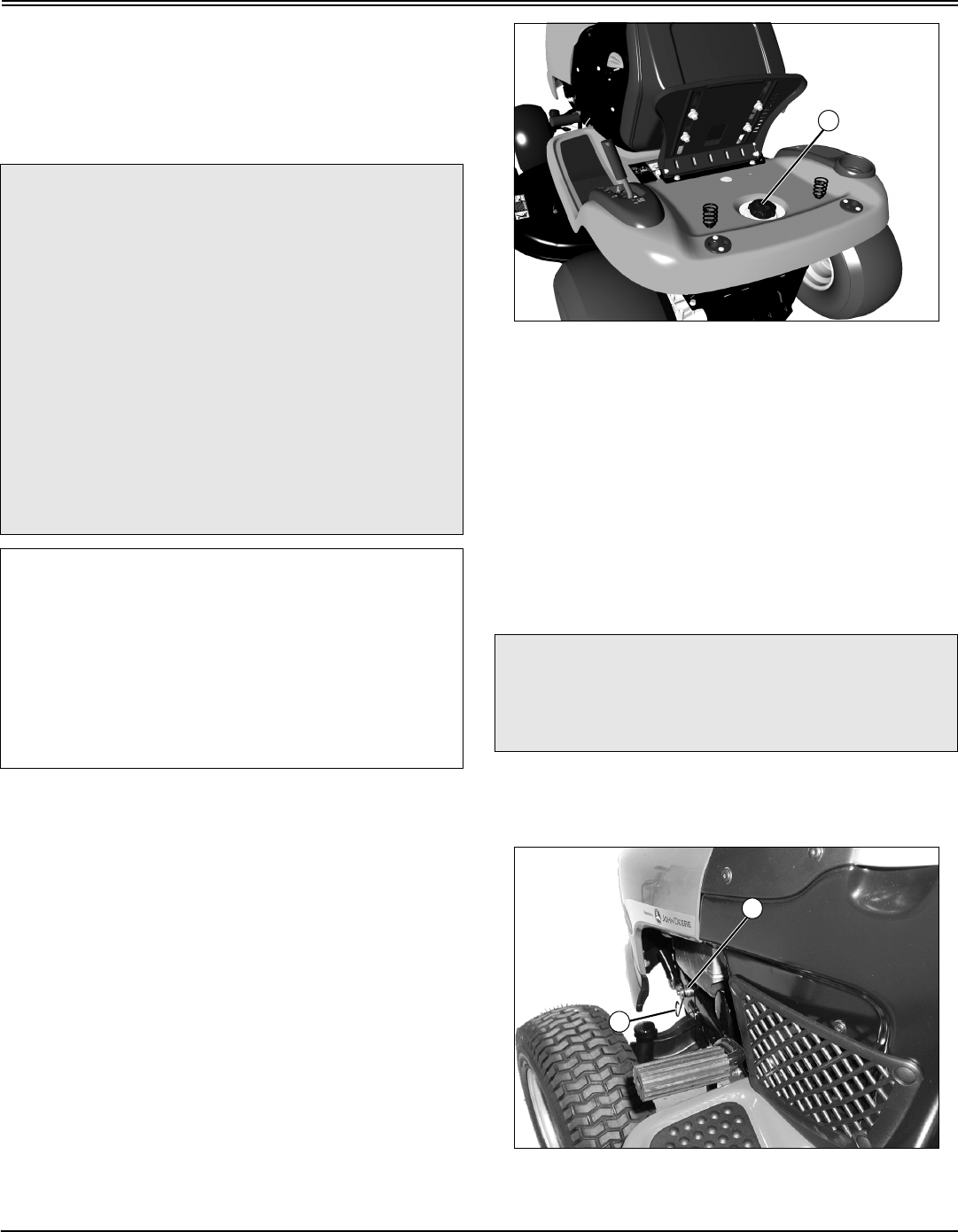
Service Miscellaneous - 50
SERVICE MISCELLANEOUS
Service Miscellaneous
Filling Fuel Tank
Use regular grade 87 octane unleaded fuel.
Add John Deere fuel stabilizer to fuel before using it in your
machine to prevent engine damage due to stale fuel. Follow
directions on stabilizer container.
1. Stop engine, let it cool several minutes before you add
fuel.
2. Lift seat.
3. Remove grass clippings and other trash from tank area.
MX7699
4. Remove fuel tank cap (A).
5. Fill tank with fuel only to bottom of filler neck. Do not
overfill.
6. Install fuel tank cap and tighten cap one full turn to
close.
7. Lower seat.
Removing and Installing Hood
Removing
1. Park machine safely. (See Parking Safely in the
SAFETY section.)
2. Let engine cool.
MX10518
3. Keep hood in the closed position and pull spring hook
c CAUTION: Avoid injury! Fuel vapors are
explosive and flammable:
•Shut engine off before filling fuel tank.
•Do not smoke while handling fuel.
•Keep fuel away from flames or sparks
•Fill fuel tank outdoors or in well ventilated
area.
•Clean up spilled fuel immediately.
•Use clean approved non-metal container to
prevent static electric discharge.
•Use clean approved plastic funnel without
screen or filter to prevent static electric
discharge.
IMPORTANT: Avoid damage! Dirt and water in fuel
can cause engine damage:
•Clean dirt and debris from the fuel tank opening.
•Use clean, fresh, stabilized fuel.
•Fill the fuel tank at the end of each day’s
operation to keep condensation out of the fuel tank.
•Use a non-metallic funnel with a plastic mesh
strainer when filling the fuel tank or container.
c CAUTION: Avoid injury! Touching hot surfaces
can burn skin. The engine and components will
be hot if the engine has been running. Allow
the engine to cool before removing hood.
A
B
A
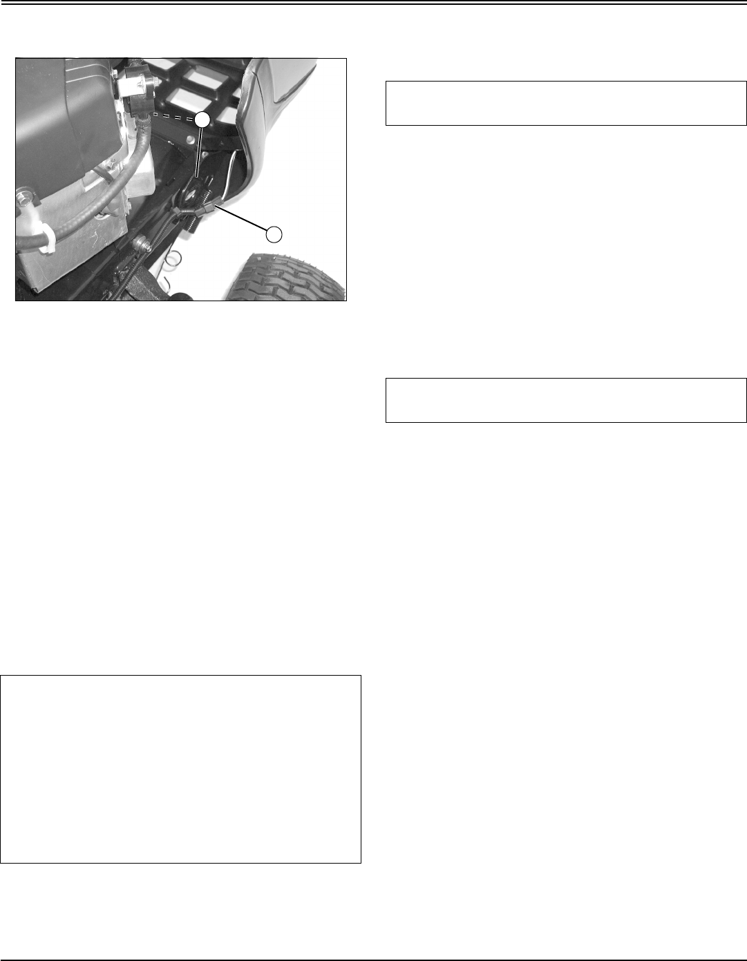
Service Miscellaneous - 51
SERVICE MISCELLANEOUS
(A) towards rear of tractor and remove from bolt (B), one on
each side.
MX10519
4. Open hood.
5. Disconnect wiring harness (C).
6. Lower hood slightly and lift hood from brackets (D).
Installing
1. Align hood brackets with tractor brackets and install
hood.
2. Connect wiring harness.
3. Close hood.
4. Pull spring hooks over bolts and release to secure hood.
Cleaning and Repairing Plastic Surfaces
Your John Deere dealer has the professional materials
needed to properly remove surface scratches from any
plastic surfaces, do not attempt to paint over marks or
scratches in plastic parts.
1. Rinse hood and entire machine with clean water to
remove dirt and dust that may scratch the surface.
2. Wash surface with clean water and a mild liquid
automotive washing soap.
3. Dry thoroughly to avoid water spots.
4. Wax the surface with a liquid automotive wax. Use
products that specifically say “contains no abrasives.”
5. Buff applied wax by hand using a clean, soft cloth.
Cleaning and Repairing Metal Surfaces
Cleaning:
Follow automotive practices to care for your vehicle painted
metal surfaces. Use a high-quality automotive wax
regularly to maintain the factory look of your vehicle’s
painted surfaces.
Repairing Minor Scratches (surface scratch):
1. Clean area to be repaired thoroughly.
2. Use automotive polishing compound to remove surface
scratches.
3. Apply wax to entire surface.
Repairing Deep Scratches (bare metal or primer
showing):
1. Clean area to be repaired with rubbing alcohol or
mineral spirits.
2. Use paint stick with factory-matched colors available
from your John Deere dealer to fill scratches. Follow
directions included on paint stick for use and for drying.
3. Smooth out surface using an automotive polishing
compound. Do not use power buffer.
4. Apply wax to surface.
IMPORTANT: Avoid damage! Improper care of
machine plastic surfaces can damage that surface:
•Do not wipe plastic surfaces when they are dry.
Dry wiping will result in minor surface scratches.
•Use a soft, clean cloth (bath towel, diaper,
automotive mitt).
•Do not use abrasive materials, such as polishing
compounds, on plastic surfaces.
•Do not spray insect repellent near machine.
C
D
IMPORTANT: Avoid damage! Do not use a power
buffer to remove wax.
IMPORTANT: Avoid damage! Do not use rubbing
compound on painted surfaces.

Troubleshooting - 52
TROUBLESHOOTING
Troubleshooting
Using Troubleshooting Chart
If you are experiencing a problem that is not listed in this
chart, see your John Deere distributor for service.
When you have checked all the possible causes listed and
you are still experiencing the problem, see your John Deere
distributor.
Engine
IF CHECK
Poor Engine Performance Dirt in fuel system or fuel is old. Replace fuel with fresh stabilized
fuel. Obtain fuel from another supplier before suspecting machine
problems. Suppliers blend fuels differently and changing suppliers
will generally solve any performance problems
Fuel blended with alcohol or ether may contribute to performance
problems by causing gum and varnish deposits, especially if fuel is
stored for several weeks or more. Obtain fresh fuel.
Engine Will Not Start Brake pedal not depressed.
PTO is engaged.
Spark plug wire is loose or disconnected.
Improper fuel.
Plugged fuel filter.
Defective safety switch.
Electrical problem - See Electrical Troubleshooting Section
Engine Is Hard To Start Carburetor is not adjusted properly or dirty.
Plugged fuel filter.
Faulty spark plug.
Stale or improper fuel.
Loose or corroded electrical connections.
Engine oil viscosity.
Engine Runs Unevenly Cooling fins plugged.
Loose electrical connections.
Choke or throttle cable sticking.
Fuel line or fuel filter plugged.
Stale or dirty fuel.
Improper fuel.
Air cleaner element plugged.
Engine Misses Under Load Faulty spark plug.
Stale or dirty fuel.
Plugged fuel filter.

Troubleshooting - 53
TROUBLESHOOTING
Engine Vapor Locks Fuel tank vent plugged.
Dirt in fuel filter.
Cooling fins plugged.
Loose hose connection at fuel filter or fuel pump.
Engine Overheats Engine air intake screen plugged.
Cooling fins plugged.
Engine oil low or too high.
Engine operated too long at a slow idle speed.
Engine Will Not Idle Spark plug not gapped correctly.
Faulty spark plug.
Operator raising off the seat.
Engine Knocks Stale or low octane fuel.
Engine overloaded.
Low engine speed.
Oil level low.
Engine Stops Or Misses When Operating On
Hillsides
Fuel tank less than half full of fuel.
Operator raising off of the seat.
Engine Backfires Faulty spark plug.
Operator raising off of the seat.
Engine Loses Power Engine overheating.
Too much oil in engine.
Dirty air cleaner.
Faulty spark plug.
Travel speed is too fast for conditions.
Improper fuel.
Excessive Fuel Consumption Choke is not fully open.
Black Exhaust Smoke Air filter is dirty or oil soaked.
Engine Stops When REVERSE Foot Pedal Is
Depressed And Attachment Is Engaged
(Hydrostatic)
Normal condition. (See Using Reverse Implement Option in the
OPERATING section.)
Engine Stops When Gear Shift Lever Is Moved To
The R (REVERSE) Position and Attachment Is
Engaged (Gear)
Normal condition. (See Using Reverse Implement Option in the
OPERATING section.)
IF CHECK

Troubleshooting - 54
TROUBLESHOOTING
Electrical
Tractor
Mower
IF CHECK
Starter Does Not Work Or Will Not Turn Engine Brake pedal is not depressed.
PTO is engaged.
Battery terminals are corroded.
Battery not charged.
Blown fuse.
Fusible Link in starting circuit is blown - See your John Deere
Dealer
Battery Will Not Charge Dead cell in the battery.
Battery cables and terminals are dirty.
Low engine speed or excessive idling.
Lights Do Not Work Light plug disconnected.
Loose or burned out bulb.
IF CHECK
Tractor Vibrates Too Much Or Rattles Excessively Attachment drive belts worn or damaged.
Traction drive belt damaged or worn.
Dirt on drive sheaves.
Blades bent or out of balance.
Tractor Will Not Move With Engine Running Parking brake locked.
Free-wheeling lever is engaged.
IF CHECK
Discharge Chute Plugged Travel speed too fast.
Grass too long.
Grass too wet.
Engine rpm not at wide open throttle.
Restricted air flow.
Belt installed incorrectly.

Troubleshooting - 55
TROUBLESHOOTING
Patches Of Grass Uncut Travel speed too fast.
Engine rpm not at wide open throttle.
Mower deck needs cleaning.
Belt Slipping Debris in sheaves.
Worn belt.
Belt tension is incorrect.
Too Much Vibration Debris on mower deck or in sheaves.
Damaged drive belt.
Damaged sheaves or sheaves out of alignment.
Blades out of balance.
Blades Scalping Grass Cutting too low.
Mower wheels not adjusted correctly.
Turning speed too fast.
Ridges in terrain.
Rough or uneven terrain.
Low tire pressure.
Mower Loads Down Tractor Engine rpm too low.
Travel speed too fast.
Debris wrapped around mower spindles.
Uneven Cut Mower deck not leveled properly.
Travel speed too fast.
Blades dull.
Mower wheels not adjusted correctly.
Tire pressure unequal.
Mower (Or Other Attachment) Stops When
Reverse Foot Pedal Is Depressed And Attachment
Is Engaged (Hydrostatic)
Normal condition. (See Using Reverse Implement Option in the
OPERATING section.)
Mower (Or Other Attachment) Stops When Gear
Shift Lever Is Moved To The R (REVERSE)
Position And Attachment Is Engaged (Gear)
Normal condition. (See Using Reverse Implement Option in the
OPERATING section.)
IF CHECK

Storage - 56
STORAGE
Storage
Storing Safety
Preparing Machine for Storage
1. Repair any worn or damaged parts. Replace parts if
necessary. Tighten loose hardware.
2. Repair scratched or chipped metal surfaces to prevent
rust.
3. Remove grass and debris from machine.
4. Clean under the deck and remove grass and debris from
inside chute and bagger.
5. Wash the machine and apply wax to metal and plastic
surfaces.
6. Run machine for five minutes to dry belts and pulleys.
7. Apply light coat of engine oil to pivot and wear points to
prevent rust.
8. Lubricate grease points.
9. Check tire pressure.
Preparing Fuel and Engine For Storage
Fuel:
If you have been using “Stabilized Fuel”, add stabilized fuel
to tank until the tank is full.
NOTE: Filling the fuel tank reduces the amount of air in
the fuel tank and helps reduce deterioration of fuel.
If you are not using “Stabilized Fuel”:
1. Park machine safely in a well-ventilated area.
NOTE: Try to anticipate the last time the tractor will be
used for the season so very little fuel is left in the fuel
tank.
2. Turn on engine and allow to run until it runs out of fuel.
3. Turn key to OFF position.
4. Mix fresh fuel and fuel stabilizer in separate container.
Follow stabilizer instructions for mixing.
5. Fill fuel tank with stabilized fuel.
6. Run engine for a few minutes to allow fuel mixture to
circulate through carburetor.
Engine:
Engine storage procedure should be used when vehicle is
not to be used for longer than 60 days.
1. Change engine oil and filter while engine is warm.
2. Service air filter if necessary.
3. Clean debris from engine air intake screen.
4. Remove spark plugs. Put 30 mL (1 oz.) of clean engine
oil in cylinders.
5. Install spark plugs, but do not connect spark plug wires.
6. Crank the engine five or six times to allow oil to be
distributed.
7. Clean the engine and engine compartment.
8. Remove battery.
9. Clean the battery and battery posts.
10.Store the battery in a cool, dry place where it will not
freeze.
NOTE: The stored battery should be recharged every
90 days.
11.Charge the battery.
12.Store the vehicle in a dry, protected place. If vehicle is
stored outside, put a waterproof cover over it.
Removing Machine From Storage
1. Check tire pressure.
2. Check engine oil level.
3. Charge battery.
4. Install battery.
c CAUTION: Avoid injury! Fuel vapors are
explosive and flammable. Engine exhaust
fumes contain carbon monoxide and can cause
serious illness or death:
•Run the engine only long enough to move
the machine to or from storage.
•Do not store vehicle with fuel in the tank
inside a building where fumes may reach an
open flame or spark.
•Allow the engine to cool before storing the
machine in any enclosure.
IMPORTANT: Avoid damage! Stale fuel can produce
varnish and plug carburetor components and affect
engine performance.
•Add fuel conditioner or stabilizer to fresh fuel
before filling tank.
IMPORTANT: Avoid damage! Prolonged exposure to
sunlight will damage the hood surface. Store
machine inside or use a cover if stored outside.

Storage - 57
STORAGE
5. Check spark plug gap. Install and tighten plugs to
specified torque.
6. Lubricate all grease points.
7. Run the engine 5 minutes without the mower or any
attachments running to allow oil to be distributed
throughout engine.
8. Be sure all shields and guards or deflectors are in place.
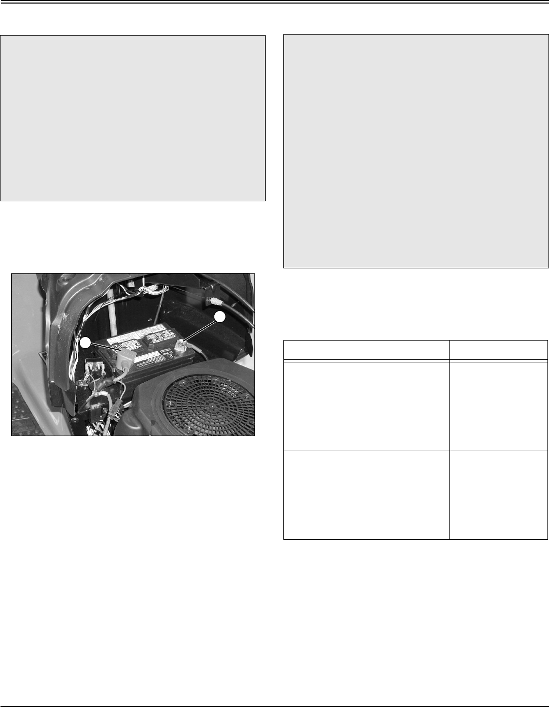
Assembly - 58
ASSEMBLY
Assembly
Charge and Connect Battery
1. Remove and discard the red positive (+) protective cap
from the positive (+) battery terminal.
2. Charge the battery.
•Battery is fully charged at 12.6 volts.
MX7686
3. Connect positive (+) battery cable (A) to battery.
4. Connect negative (–) battery cable (B).
5. Apply general purpose grease or silicone spray to
terminal to help prevent corrosion.
6. Slide red cover over positive battery cable.
Check Tire Pressure
1. Check tires for damage.
2. Check tire pressure with an accurate gauge.
3. Check that tires have equal air pressure. Add or remove
air, if necessary.
Adjust Mower Level
Adjust mower level. (See Adjusting Mower Level in the
OPERATING section.)
Check Machine Safety System
Perform safety system check to make sure the electronic
safety interlock circuit is functioning properly. Perform all
c CAUTION: Avoid injury! The battery produces a
flammable and explosive gas. The battery may
explode:
•Do not smoke near battery.
•Wear eye protection and gloves.
•Do not allow direct metal contact across
battery posts.
•Remove negative cable first when
disconnecting.
•Install negative cable last when connecting.
A
B
c CAUTION: Avoid injury! Explosive separation
of tire and rim parts is possible when they are
serviced incorrectly:
•Do not attempt to mount a tire without the
proper equipment and experience to perform
the job.
•Do not inflate the tires above the
recommended pressure.
•Do not weld or heat a wheel and tire
assembly. Heat can cause an increase in air
pressure resulting in an explosion. Welding
can structurally weaken or deform the wheel.
•Do not stand in front or over the tire
assembly when inflating. Use a clip-on chuck
and extension hose long enough to allow you
to stand to one side.
Tire Size Pressure
Front:
Models 1742 and 17.542
•15 x 6.00 - 6
Models 2048 and 2548
•16 x 6.5 - 8
97 kPa (14 psi)
97 kPa (14 psi)
Rear:
Models 1742 and 17.542
•20 x 8.0 - 8
Models 2048 and 2548
•22 x 9.5 - 12
69 kPa (10 psi)
69 kPa (10 psi)
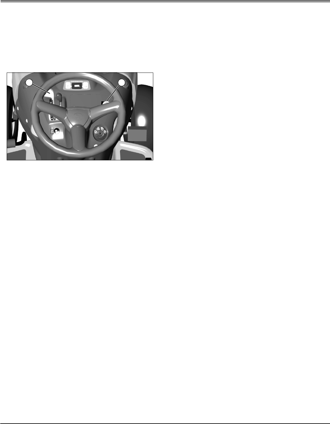
Assembly - 59
ASSEMBLY
tests. (See Testing Safety System in the OPERATING
section.)
Break-In Electric PTO Clutch (Models 2048
and 2548 Only)
1. Start engine and move tractor to flat level surface.
MX10501
2. Push throttle lever (A) up to full throttle position.
3. Engage PTO (B) and allow mower to run for 10 seconds.
4. Disengage PTO and wait 10 seconds.
5. Repeat steps 2 and 3 for 12-15 cycles.
NOTE: PTO clutch is now properly burnished.
A B

Specifications - 60
SPECIFICATIONS
Specifications
Gear Model L1742
Engine Manufacturer . . . . . . . . . . . . . . . . . . . . . . . . . . . . . . . . . . . . . . . . . . . . . . . . . . . . . . . . . . . . . . . Briggs & Stratton
Horsepower . . . . . . . . . . . . . . . . . . . . . . . . . . . . . . . . . . . . . . . . . . . . . . . . . . . . . . . . . . . . . . . . . . . . . . . . 12.7 kW (17 hp)
Displacement . . . . . . . . . . . . . . . . . . . . . . . . . . . . . . . . . . . . . . . . . . . . . . . . . . . . . . . . . . . . . . . . . . . . . 508 cc (31 cu.in.)
Spark Plug-Gap . . . . . . . . . . . . . . . . . . . . . . . . . . . . . . . . . . . . . . . . . . . . . . . . . . . . . . . . . . . . . . . . . . . . 1 mm (0.040 in.)
Cylinders . . . . . . . . . . . . . . . . . . . . . . . . . . . . . . . . . . . . . . . . . . . . . . . . . . . . . . . . . . . . . . . . . . . . . . . . . . . . . . . . . . . . . One
Oil Filter. . . . . . . . . . . . . . . . . . . . . . . . . . . . . . . . . . . . . . . . . . . . . . . . . . . . . . . . . . . . . . . . . . . . . . . . . . . . . . . . . . . . . None
Air Filter. . . . . . . . . . . . . . . . . . . . . . . . . . . . . . . . . . . . . . . . . . . . . . . . . . . . . . . . . . . . . . . . . . . . . . . . . . . Paper with Foam
Transmission . . . . . . . . . . . . . . . . . . . . . . . . . . . . . . . . . . . . . . . . . . . . . . . . . . . . . . . . . . . . . . . . . . . . . . . .Gear Transaxle
Transaxle Manufacturer . . . . . . . . . . . . . . . . . . . . . . . . . . . . . . . . . . . . . . . . . . . . . . . . . . . . . . . . . . . . . . . . . . . Dana 4360
Travel Speeds . . . . . . . . . . . . . . . . . . . . . . . . . . . . . . . . . . . . . . . . . . . . . . . . . . . . . . . . . . . . . . . . . . . . . . . . . . . . . . . . . . . 5
Gear Speed Range
1st . . . . . . . . . . . . . . . . . . . . . . . . . . . . . . . . . . . . . . . . . . . . . . . . . . . . . . . . . . . . . . . . . . . . . . . . . . . . . 2.4 km/h (1.5 mph)
2nd . . . . . . . . . . . . . . . . . . . . . . . . . . . . . . . . . . . . . . . . . . . . . . . . . . . . . . . . . . . . . . . . . . . . . . . . . . . . 3.2 km/h (2.0 mph)
3rd . . . . . . . . . . . . . . . . . . . . . . . . . . . . . . . . . . . . . . . . . . . . . . . . . . . . . . . . . . . . . . . . . . . . . . . . . . . . . 5.0 km/h (3.1 mph)
4th . . . . . . . . . . . . . . . . . . . . . . . . . . . . . . . . . . . . . . . . . . . . . . . . . . . . . . . . . . . . . . . . . . . . . . . . . . . . . 6.4 km/h (4.0 mph)
5th . . . . . . . . . . . . . . . . . . . . . . . . . . . . . . . . . . . . . . . . . . . . . . . . . . . . . . . . . . . . . . . . . . . . . . . . . . . . . 8.0 km/h (5.0 mph)
Reverse . . . . . . . . . . . . . . . . . . . . . . . . . . . . . . . . . . . . . . . . . . . . . . . . . . . . . . . . . . . . . . . . . . . . . . . . . .3.7 km/h (2.3 mph)
Automatic Model L17.542
Engine Manufacturer . . . . . . . . . . . . . . . . . . . . . . . . . . . . . . . . . . . . . . . . . . . . . . . . . . . . . . . . . . . . . . . . . . . . . . . . Kohler
Horsepower . . . . . . . . . . . . . . . . . . . . . . . . . . . . . . . . . . . . . . . . . . . . . . . . . . . . . . . . . . . . . . . . . . . . . . . . 13 kW (17.5 hp)
Displacement . . . . . . . . . . . . . . . . . . . . . . . . . . . . . . . . . . . . . . . . . . . . . . . . . . . . . . . . . . . . . . . . . . . . 490 cc (29.9 cu.in.)
Spark Plug-Gap . . . . . . . . . . . . . . . . . . . . . . . . . . . . . . . . . . . . . . . . . . . . . . . . . . . . . . . . . . . . . . . . . . . . 1 mm (0.040 in.)
Cylinders . . . . . . . . . . . . . . . . . . . . . . . . . . . . . . . . . . . . . . . . . . . . . . . . . . . . . . . . . . . . . . . . . . . . . . . . . . . . . . . . . . . . . One
Oil Filter. . . . . . . . . . . . . . . . . . . . . . . . . . . . . . . . . . . . . . . . . . . . . . . . . . . . . . . . . . . . . . . . . . . . . . . . . . . . . . . . . . . . . . Yes
Air Filter. . . . . . . . . . . . . . . . . . . . . . . . . . . . . . . . . . . . . . . . . . . . . . . . . . . . . . . . . . . . . . . . . . . . . . . . . . . Paper with Foam
Transmission . . . . . . . . . . . . . . . . . . . . . . . . . . . . . . . . . . . . . . . . . . . . . . . . . . . . . . . . . . . . . . . . . . . . . . . . . . .Hydrostatic
Transaxle Manufacturer . . . . . . . . . . . . . . . . . . . . . . . . . . . . . . . . . . . . . . . . . . . . . . . . . . . . . . . . . . . . . . . Tuff Torq™ K46
Travel Speed - Forward . . . . . . . . . . . . . . . . . . . . . . . . . . . . . . . . . . . . . . . . . . . . . . . . . . . . . . 0 - 9.2 km/h (0 - 5.7 mph)
Travel Speed - Reverse . . . . . . . . . . . . . . . . . . . . . . . . . . . . . . . . . . . . . . . . . . . . . . . . . . . . . . . .0 - 5.5 km/h (0 - 3.4 mph)
Automatic Models L2048 and L2548
Engine Manufacturer . . . . . . . . . . . . . . . . . . . . . . . . . . . . . . . . . . . . . . . . . . . . . . . . . . . . . . . . . . . . . . . Briggs & Stratton
Horsepower (2048) . . . . . . . . . . . . . . . . . . . . . . . . . . . . . . . . . . . . . . . . . . . . . . . . . . . . . . . . . . . . . . . . . . 14.9 kW (20 hp)
Horsepower (2548) . . . . . . . . . . . . . . . . . . . . . . . . . . . . . . . . . . . . . . . . . . . . . . . . . . . . . . . . . . . . . . . . . . 18.6 kW (25 hp)
Displacement (2048) . . . . . . . . . . . . . . . . . . . . . . . . . . . . . . . . . . . . . . . . . . . . . . . . . . . . . . . . . . . . . . 656 cc (40.0 cu.in.)
Displacement (2548) . . . . . . . . . . . . . . . . . . . . . . . . . . . . . . . . . . . . . . . . . . . . . . . . . . . . . . . . . . . . . . 724 cc (44.2 cu.in.)

Specifications - 61
SPECIFICATIONS
Spark Plug-Gap . . . . . . . . . . . . . . . . . . . . . . . . . . . . . . . . . . . . . . . . . . . . . . . . . . . . . . . . . . . . . . . . . . . . 1 mm (0.040 in.)
Cylinders . . . . . . . . . . . . . . . . . . . . . . . . . . . . . . . . . . . . . . . . . . . . . . . . . . . . . . . . . . . . . . . . . . . . . . . . . . . . . . . . . . . . . Two
Oil Filter. . . . . . . . . . . . . . . . . . . . . . . . . . . . . . . . . . . . . . . . . . . . . . . . . . . . . . . . . . . . . . . . . . . . . . . . . . . . . . . . . . . . . . Yes
Air Filter. . . . . . . . . . . . . . . . . . . . . . . . . . . . . . . . . . . . . . . . . . . . . . . . . . . . . . . . . . . . . . . . . . . . . . Dry, Replaceable Foam
Transmission . . . . . . . . . . . . . . . . . . . . . . . . . . . . . . . . . . . . . . . . . . . . . . . . . . . . . . . . . . . . . . . . . . . . . . . . . . .Hydrostatic
Transaxle Manufacturer . . . . . . . . . . . . . . . . . . . . . . . . . . . . . . . . . . . . . . . . . . . . . . . . . . . . . . . . . . . . Tuff Torq™ HD K46
Travel Speed - Forward . . . . . . . . . . . . . . . . . . . . . . . . . . . . . . . . . . . . . . . . . . . . . . . . . . . . . . 0 - 8.4 km/h (0 - 5.2 mph)
Travel Speed - Reverse . . . . . . . . . . . . . . . . . . . . . . . . . . . . . . . . . . . . . . . . . . . . . . . . . . . . . . . .0 - 4.7 km/h (0 - 2.9 mph)
Electrical System (All Models)
Charging System . . . . . . . . . . . . . . . . . . . . . . . . . . . . . . . . . . . . . . . . . . . . . . . . . . . . . . . . . . . . . . . . . . .Regulated Circuit
Charging System Capacity (1742 and 17.542) . . . . . . . . . . . . . . . . . . . . . . . . . . . . . . . . . . . . . . . . . . . . . . . . . . . . . 9 Amp
Charging System Capacity (2048 and 2548) . . . . . . . . . . . . . . . . . . . . . . . . . . . . . . . . . . . . . . . . . . . . . . . . . . . . . 16 Amp
Battery Voltage . . . . . . . . . . . . . . . . . . . . . . . . . . . . . . . . . . . . . . . . . . . . . . . . . . . . . . . . . . . . . . . . . . . . . . . . . . . . .12 Volts
Battery Type . . . . . . . . . . . . . . . . . . . . . . . . . . . . . . . . . . . . . . . . . . . . . . . . . . . . . . . . . . . . . . . . . . . . . . . . . .BCI Group U1
Capacities
Model 1742
Crankcase without oil filter . . . . . . . . . . . . . . . . . . . . . . . . . . . . . . . . . . . . . . . . . . . . . . . . . . . . . . . . . . . . . . 1.4 L (1.5 qt)
Fuel . . . . . . . . . . . . . . . . . . . . . . . . . . . . . . . . . . . . . . . . . . . . . . . . . . . . . . . . . . . . . . . . . . . . . . . . . . . . . . . 7.9 L (2.1 gal)
Model 17.542, 2048 and 2548
Crankcase without oil filter . . . . . . . . . . . . . . . . . . . . . . . . . . . . . . . . . . . . . . . . . . . . . . . . . . . . . . . . . . . . . 1.8 L (1.75 qt)
Crankcase with oil filter . . . . . . . . . . . . . . . . . . . . . . . . . . . . . . . . . . . . . . . . . . . . . . . . . . . . . . . . . . . . . . . . . . 1.9 L (2 qt)
Fuel . . . . . . . . . . . . . . . . . . . . . . . . . . . . . . . . . . . . . . . . . . . . . . . . . . . . . . . . . . . . . . . . . . . . . . . . . . . . . . . 7.9 L (2.1 gal)
Dimensions (All Models)
Height . . . . . . . . . . . . . . . . . . . . . . . . . . . . . . . . . . . . . . . . . . . . . . . . . . . . . . . . . . . . . . . . . . . . . . . . . . . . . 98 cm (38.6 in.)
Length (Overall) . . . . . . . . . . . . . . . . . . . . . . . . . . . . . . . . . . . . . . . . . . . . . . . . . . . . . . . . . . . . . . . . . . . . 152.4 cm (60 in.)
Width (Overall) . . . . . . . . . . . . . . . . . . . . . . . . . . . . . . . . . . . . . . . . . . . . . . . . . . . . . . . . . . . . . . . . . . . . . . . 91 cm (36 in.)
Weight: 1742 and 17.542 . . . . . . . . . . . . . . . . . . . . . . . . . . . . . . . . . . . . . . . . . . . . . . . . . . . . . . . . . . . . . . 210 kg (462 lb)
Weight: 2048 and 2548 . . . . . . . . . . . . . . . . . . . . . . . . . . . . . . . . . . . . . . . . . . . . . . . . . . . . . . . . . . . . . . . 241 kg (532 lb)
Tires
Models 1742 and 17.542
Size (Front) . . . . . . . . . . . . . . . . . . . . . . . . . . . . . . . . . . . . . . . . . . . . . . . . . . . . . . . . . . . . . . . . . . . . . . . . . . . . 15 x 6.00 - 6
Size (Rear). . . . . . . . . . . . . . . . . . . . . . . . . . . . . . . . . . . . . . . . . . . . . . . . . . . . . . . . . . . . . . . . . . . . . . . . . . . . . . 20 x 8.0 - 8

Specifications - 62
SPECIFICATIONS
Tire Pressure (Front) . . . . . . . . . . . . . . . . . . . . . . . . . . . . . . . . . . . . . . . . . . . . . . . . . . . . . . . . . . . . . . . . . . 97 kPa (14 psi)
Tire Pressure (Rear) . . . . . . . . . . . . . . . . . . . . . . . . . . . . . . . . . . . . . . . . . . . . . . . . . . . . . . . . . . . . . . . . . . 69 kPa (10 psi)
Models 2048 and 2548
Size (Front) . . . . . . . . . . . . . . . . . . . . . . . . . . . . . . . . . . . . . . . . . . . . . . . . . . . . . . . . . . . . . . . . . . . . . . . . . . . . . 16 x 6.5 - 8
Size (Rear). . . . . . . . . . . . . . . . . . . . . . . . . . . . . . . . . . . . . . . . . . . . . . . . . . . . . . . . . . . . . . . . . . . . . . . . . . . . . 22 x 9.5 - 12
Tire Pressure (Front) . . . . . . . . . . . . . . . . . . . . . . . . . . . . . . . . . . . . . . . . . . . . . . . . . . . . . . . . . . . . . . . . . . 97 kPa (14 psi)
Tire Pressure (Rear) . . . . . . . . . . . . . . . . . . . . . . . . . . . . . . . . . . . . . . . . . . . . . . . . . . . . . . . . . . . . . . . . . . 69 kPa (10 psi)
Mower Deck - 42 (3 in 1)
Blades-Rotary . . . . . . . . . . . . . . . . . . . . . . . . . . . . . . . . . . . . . . . . . . . . . . . . . . . . . . . . . . . . . . . . . . . . . . . . . . . . . . . . . . . 2
Blade Bolt Torque . . . . . . . . . . . . . . . . . . . . . . . . . . . . . . . . . . . . . . . . . . . . . . . . . . . . . . . . . . . . . . . . . . 62 N•m (46 lb-ft)
Cutting Height-Approx. . . . . . . . . . . . . . . . . . . . . . . . . . . . . . . . . . . . . . . . . . . . . . . . . . . . . . . . . . . . 25–102 mm (1–4 in.)
Cutting Width . . . . . . . . . . . . . . . . . . . . . . . . . . . . . . . . . . . . . . . . . . . . . . . . . . . . . . . . . . . . . . . . . . . . . . 1067 mm (42 in.)
Mower Deck - 48 (3 in 1)
Blades-Rotary . . . . . . . . . . . . . . . . . . . . . . . . . . . . . . . . . . . . . . . . . . . . . . . . . . . . . . . . . . . . . . . . . . . . . . . . . . . . . . . . . . . 3
Blade Bolt Torque . . . . . . . . . . . . . . . . . . . . . . . . . . . . . . . . . . . . . . . . . . . . . . . . . . . . . . . . . . . . . . . . . . 62 N•m (46 lb-ft)
Cutting Height-Approx. . . . . . . . . . . . . . . . . . . . . . . . . . . . . . . . . . . . . . . . . . . . . . . . . . . . . . . . . . . . 25–102 mm (1–4 in.)
Cutting Width . . . . . . . . . . . . . . . . . . . . . . . . . . . . . . . . . . . . . . . . . . . . . . . . . . . . . . . . . . . . . . . . . . . . . . 1219 mm (48 in.)
Recommended Lubricants
Engine Oil . . . . . . . . . . . . . . . . . . . . . . . . . . . . . . . . . . . . . . . . . . . . . . . . . . . . . . . . . API Service Classification SG or SF
Grease . . . . . . . . . . . . . . . . . . . . . . . . . . . . . . . . . . . . . . . . . . . . . . . . . . . . . . . . . . . . . . . . .SAE Multi-Purpose EP Grease
Lubricant . . . . . . . . . . . . . . . . . . . . . . . . . . . . . . . . . . . . . . . . . . . . . . . . . . . . . . . . . . . . . . . . . .General All-Purpose Spray
(Specifications and design subject to change without notice.)

Warranty - 63
WARRANTY
Warra nty
Limited Warranty For New Scotts Brand
Products-U.S. Only
Manufactured by John Deere
(U.S. Only)
A. GENERAL PROVISIONS - The warranties described
below are provided by John Deere Company (“John
Deere”) to the original purchasers of new Scotts Brand
Products Manufactured by John Deere. Under these
warranties, John Deere will repair or replace, at its option,
any covered part which is found to be defective in material
or workmanship during the applicable warranty term.
Warranty service must be performed by a dealer or service
center authorized by John Deere to service the type of
product involved, which will use only new or
remanufactured parts or components furnished by John
Deere. Warranty service will be performed without charge
to the purchaser for parts or labor. The purchaser will be
responsible, however, for any service call and/or
transportation of product to and from the dealer's or service
center’s place of business, for any premium charged for
overtime labor requested by the purchaser and for any
service and/or maintenance not directly related to any
defect covered under the warranties below.
B. WHAT IS WARRANTED - All parts of any new Scotts
Brand Product Manufactured by John Deere, except
batteries, are warranted for the number of months or
operating hours specified below. Warranty statements
required by law covering engine emission-related parts and
components, are found in the Operator’s Manual delivered
with the machine.
Each warranty term begins on the date of product sale to
the purchaser.
C. WHAT IS NOT WARRANTED - JOHN DEERE IS NOT
RESPONSIBLE FOR THE FOLLOWING: (1) Used
products; (2) Any product that has been altered or modified
in ways not approved by John Deere; (3) Depreciation or
damage caused by normal wear, lack of reasonable and
proper maintenance, failure to follow operating instructions,
misuse, lack of proper protection during storage or
accident; (4) Normal maintenance parts and service.
D. SECURING WARRANTY SERVICE - To secure
warranty service, the purchaser must (1) report the product
defect to an authorized dealer and request repair within the
applicable warranty term, (2) present evidence of the
warranty start date, and (3) make the product available to
the dealer or service center within a reasonable period of
time.
E. LIMITATION OF IMPLIED WARRANTIES AND OTHER
REMEDIES - SCOTTS BRAND PRODUCTS
MANUFACTURED BY JOHN DEERE - to the extent
permitted by law, neither John Deere nor any company
affiliated with it makes any warranties, representations, or
promises as to the quality, performance or freedom from
defect of the Scotts Brand Products Manufactured by John
Deere covered by this warranty. IMPLIED WARRANTIES
OF MERCHANTABILITY AND FITNESS FOR A
PARTICULAR PURPOSE, TO THE EXTENT
APPLICABLE, SHALL BE LIMITED IN DURATION TO THE
APPLICABLE PERIOD OF WARRANTY SET FORTH ON
THIS PAGE. THE PURCHASER’S ONLY REMEDIES IN
CONNECTION WITH THE BREACH OR PERFORMANCE
OF ANY WARRANTY ON THE SCOTTS BRAND
PRODUCTS MANUFACTURED BY JOHN DEERE ARE
THOSE SET FORTH ON THIS PAGE. IN NO EVENT WILL
THE DEALER, JOHN DEERE OR ANY COMPANY
AFFILIATED WITH JOHN DEERE BE LIABLE FOR
INCIDENTAL OR CONSEQUENTIAL DAMAGES. (Note:
Some states do not allow limitations on how long an implied
warranty lasts or the exclusion or limitation of incidental or
consequential damages so the above limitations and
exclusions may not apply to you.) This warranty gives you
specific legal rights, and you may also have other rights
which vary from state to state.
F. NO DEALER WARRANTY - THE SELLING DEALER
MAKES NO WARRANTY OF ITS OWN AND THE
DEALER HAS NO AUTHORITY TO MAKE ANY
REPRESENTATION OR PROMISE ON BEHALF OF JOHN
DEERE, OR TO MODIFY THE TERMS OR LIMITATIONS
OF THIS WARRANTY IN ANY WAY.
G. FAILURE DUE TO IMPROPER SET-UP IS NOT
COVERED UNDER WARRANTY.
H. If further information is desired, contact a servicing
dealer. For the location of servicing dealers in your area call
1-877-356-3698.
Limited Warranty For New Scotts Brand
Products
Manufactured by John Deere
(Canada Only)
A. GENERAL PROVISIONS - The warranties described
below are provided by John Deere Limited ("John Deere")
to the original purchasers of new Scotts Brand Products
Manufactured by John Deere. Under these warranties,
John Deere will repair or replace, at its option, any part
covered under these warranties which is found to be
defective in material or workmanship during the applicable
EQUIPMENT USE WARRANTY
TERM
1) IN RESIDENTIAL (Private
Homeowner) APPLICATION
24 Months
2) IN ANY OTHER APPLICATION 90 Days

Warranty - 64
WARRANTY
warranty term. Warranty service must be performed by a
dealer or service center authorized by John Deere to
service the type of product involved, which will use only
new or remanufactured parts or components furnished by
John Deere. Warranty service will be performed without
charge to the purchaser for parts or labor. The purchaser
will be responsible, however, for any service call and/or
transportation of product to and from the dealer's or service
center’s place of business, except where prohibited by law,
for any premium charged for overtime labor requested by
the purchaser and for any service and/or maintenance not
directly related to any defect covered under the warranties
below.
B. WHAT IS WARRANTED - Subject to paragraph C below,
all parts of any new Scotts Brand Product Manufactured by
John Deere, except batteries, are warranted for the number
of months or days specified below. Warranty statements
required by law covering engine emission-related parts and
components, if any, are found in the Operator’s Manual
delivered with the product.
Each warranty term begins on the date of product sale to
the purchaser.
C. WHAT IS NOT WARRANTED - JOHN DEERE IS NOT
RESPONSIBLE FOR THE FOLLOWING: (1) Used
products; (2) Any product that has been altered or modified
in ways not approved by John Deere; (3) Depreciation or
damage caused by normal wear, lack of reasonable and
proper maintenance, failure to follow operating instructions,
misuse, lack of proper protection during storage or
accident; (4) Normal maintenance parts and service
D. SECURING WARRANTY SERVICE - To secure
warranty service, the purchaser must (1) report the product
defect to an authorized dealer and request repair or
replacement within the applicable warranty term, (2)
present evidence of the warranty start date, and (3) make
the product available to the dealer or service center within a
reasonable period of time.
E. LIMITATION OF IMPLIED WARRANTIES AND OTHER
REMEDIES - SCOTTS BRAND PRODUCTS
MANUFACTURED BY JOHN DEERE - TO THE EXTENT
PERMITTED BY LAW, NEITHER JOHN DEERE NOR ANY
COMPANY AFFILIATED WITH IT MAKES ANY
WARRANTIES, REPRESENTATIONS, CONDITIONS OR
PROMISES RESPECTING THE SCOTTS BRAND
PRODUCTS MANUFACTURED BY JOHN DEERE AND
COVERED BY THIS WARRANTY OTHER THAN THOSE
LISTED ABOVE. THIS EXCLUSION INCLUDES
FUNDAMENTAL TERMS, REPRESENTATIONS,
CONDITIONS AND WARRANTIES WHICH MAY BE
EXPRESSED OR IMPLIED, VERBAL OR OTHERWISE,
INCLUDING IMPLIED OR STATUTORY CONDITIONS OR
WARRANTIES OF MERCHANTABILITY AND FITNESS,
WHETHER PURSUANT TO THE SALE OF GOODS ACT
OR ANY OTHER STATUTE OF ANY PROVINCE OR
OTHERWISE, EXCEPT WHERE SUCH IMPLIED OR
STATUTORY CONDITIONS OR WARRANTIES MAY NOT
BE EXCLUDED BY LAW.
F. REMEDIES EXCLUSIVE - THE PURCHASER’S ONLY
REMEDIES IN CONNECTION WITH THE BREACH OR
PERFORMANCE OF ANY WARRANTY ON THE SCOTTS
BRAND PRODUCTS MANUFACTURED BY JOHN
DEERE ARE THOSE SET FORTH IN THIS WARRANTY
EXCEPT FOR THOSE REMEDIES PROVIDED BY LAW
WHICH MAY NOT BE EXCLUDED. IN NO EVENT WILL
THE DEALER, JOHN DEERE OR ANY COMPANY
AFFILIATED WITH JOHN DEERE, BE LIABLE FOR
INCIDENTAL OR CONSEQUENTIAL DAMAGES OR
INJURIES OR BE LIABLE FOR DAMAGES SUFFERED
BY THE PURCHASER AS A RESULT OF FUNDAMENTAL
BREACHES OF CONTRACT OR BREACHES OF
FUNDAMENTAL TERMS. The limitations of liability
contained in this warranty shall only be effective to the
extent permitted by law. This warranty gives you specific
legal rights and you may also have other rights which vary
from jurisdiction to jurisdiction.
G. NO DEALER WARRANTY - EXCEPT FOR
WARRANTIES WHICH MAY NOT BE EXCLUDED BY
LAW, THE SELLING DEALER MAKES NO WARRANTY
OF ITS OWN AND THE SELLING DEALER HAS NO
AUTHORITY TO MAKE ANY REPRESENTATION OR
PROMISE ON BEHALF OF JOHN DEERE, OR TO
MODIFY THE TERMS OR LIMITATIONS OF THIS
WARRANTY IN ANY WAY.
H. FAILURE DUE TO IMPROPER SET-UP IS NOT
COVERED UNDER WARRANTY.
I. If further information is desired, contact a servicing
dealer. For the location of servicing dealers in your area call
1-877-356-3698.
John Deere, Federal and California Emission
Control System Warranty (Small Off-Road
Gas Engines)
Your Warranty Rights and Obligations
The United States Environmental Protection Agency (EPA),
the California Air Resources Board (CARB) and John
Deere are pleased to explain the emission control system
warranty on your 1995 or later small off-road equipment
EQUIPMENT USE WARRANTY
TERM
1) IN RESIDENTIAL (Private
Homeowner) APPLICATION
24 Months
2) IN ANY OTHER APPLICATION 90 Days

Warranty - 65
WARRANTY
engine. In California, 1995 and later small off-road
equipment engines must be designed, built and equipped
to meet the State’s stringent anti-smog standards. In other
states, 1997 and later model year equipment engines must
be designed, built and equipped to meet the U.S. EPA
regulations for small non-road, spark ignition engines. John
Deere must warrant the emission control system on your
small off-road equipment engine for the periods of time
listed below provided there has been no abuse, neglect or
improper maintenance of your small off-road equipment
engine.
Your emission control system may include parts such as
the carburetor, fuel-injection system and ignition system.
Also included may be connectors and other emission
related assemblies.
Where a warrantable condition exists, John Deere will
repair your small off-road equipment engine at no cost to
you including diagnosis, parts and labor.
John Deere Emission Control System Warranty
Coverage
In California, 1995 and later small off-road equipment
engines are warranted relative to emission control parts for
two years. In other states, 1997 and later model year
equipment engines are warranted relative to emission
control parts for two years. If any emission related part on
your engine is defective, the part will be repaired or
replaced by John Deere.
Owner’s Warranty Responsibilities
As the small off-road equipment engine owner, you are
responsible for the performance of the required
maintenance listed in your owner’s manual. John Deere
recommends that you retain all receipts covering
maintenance on your small off-road equipment engine, but
John Deere cannot deny warranty solely for lack of receipts
or for your failure to ensure the performance of all
scheduled maintenance.
As the small off-road equipment engine owner, you should
however be aware that John Deere may deny you warranty
coverage if your small off-road equipment engine or a part
has failed due to abuse, neglect, improper maintenance or
unapproved modifications.
You are responsible for presenting your small off-road
equipment engine to an authorized John Deere
Commercial and Consumer Equipment Retailer as soon as
a problem exists. The warranty repairs should be
completed in a reasonable amount of time, not to exceed
30 days.
If you have any questions regarding your warranty rights
and responsibilities, you should contact your John Deere
Commercial and Consumer Equipment Retailer, or the
John Deere Customer Communications Center at 1-800-
537-8233.
Length Of Warranty Coverage
John Deere warrants to the initial owner and each
subsequent purchaser that the small off-road equipment
engine is:
•Designed, built and equipped so as to conform with all
applicable regulations adopted by the California Air
Resources Board (CARB) for 1995 and later equipment
engines, and all applicable regulations of the United States
Environmental Protection Agency (EPA) for 1997 and later
equipment engines; and
•Free from defects in materials and workmanship which
can cause the failure of an emission warranted part for a
period of two years after the engine is delivered to the initial
retail purchaser. John Deere is liable for damages to other
engine components caused by the failure of a warranted
part during the warranty period. If any emission related part
on your engine is defective, the part will be repaired or
replaced by John Deere.
Warranted Parts
Coverage under this warranty extends only to the parts
listed below (the emission control system parts) to the
extent these parts were present on the engine purchased.
Fuel Metering System:
•Carburetor and internal parts (or fuel injection system).
•Air/fuel ratio feedback and control system.
•Cold start enrichment system.
Air Induction System:
•Air Cleaner
•Intake manifold.
Ignition System:
•Spark plugs.
•Magneto or electronic ignition system.
•Spark advance/retard system.
Catalyst System:
•Exhaust manifold.
Miscellaneous Items Used in Above Systems
•Vacuum and temperature switches.
•Electronic controls.
•Hoses, belts, connectors and assemblies.
Since emission related parts may vary slightly from model
to model, certain models may not contain all of these parts
and certain models may contain functionally equivalent
parts.
Warranty Service And Charges
Warranty service shall be provided during customary

Warranty - 66
WARRANTY
business hours at any authorized John Deere Commercial
and Consumer Equipment Retailer located within the
United States of America. Repair or replacement of any
warranted part will be performed at no charge to the owner,
including diagnostic labor which leads to the determination
that a warranted part is defective, if the diagnostic work is
performed at an authorized John Deere Commercial and
Consumer Equipment Retailer. Any parts replaced under
this warranty shall become the property of John Deere.
Maintenance Warranty Coverage
a) Any warranted part that is not scheduled for replacement
as required maintenance must be warranted as to defects
for the warranty period. Any such part repaired or replaced
under the warranty must be warranted for the remaining
warranty period.
b) Any warranted part that is scheduled only for regular
inspection to the effect of “repair or replace as necessary”
must be warranted as to defects for the warranty period.
Any such part repaired or replaced under the warranty
must be warranted for the remaining warranty period.
c) Any warranted part which is scheduled for replacement
as required maintenance must be warranted as to defects
only for the period of time up to the first scheduled
replacement for that part. Any such part repaired or
replaced under the warranty must be warranted for the
remainder of the period prior to the first scheduled
replacement point for that part.
d) Normal maintenance, replacement or repair of emission
control devices and systems, which are being done at the
customers expense, may be performed by any repair
establishment or individual; however, warranty repairs must
be performed by an authorized John Deere Commercial
and Consumer Equipment Retailer.
e) Any replacement part that is equivalent in performance
and durability may be used in the performance of any non-
warranty maintenance or repairs, and shall not reduce the
warranty obligations of John Deere.
Consequential Warranty Coverage
Warranty coverage shall extend to the failure of any engine
components caused by the failure of any warranted part still
under warranty.
Limitations
This Emission Control System Warranty shall NOT cover
any of the following:
a) Repair or replacement required as a result of (i) misuse
or neglect, (ii) improper maintenance or unapproved
modifications, (iii) repairs improperly performed or
replacements improperly installed, (iv) use of replacement
parts or accessories not conforming to John Deere
specifications which adversely affect performance and/or
durability, (v) alterations or modifications not recommended
or approved in writing by John Deere.
b) Replacement parts, other services and adjustments
necessary for normal maintenance.
c) Transportation to and from the John Deere Commercial
and Consumer Equipment Retailer, or service calls made
by the Retailer.
Limited Liability
a) The liability of John Deere under this Emission Control
System Warranty is limited solely to the remedying of
defects in materials or workmanship. This warranty does
not cover inconvenience or loss of use of the small off-road
equipment engine or transportation of the engine to or from
the John Deere Commercial And Consumer Equipment
Retailer. JOHN DEERE SHALL NOT BE LIABLE FOR ANY
OTHER EXPENSE, LOSS, OR DAMAGE, WHETHER
DIRECT, INCIDENTAL, CONSEQUENTIAL (EXCEPT AS
LISTED ABOVE UNDER “COVERAGE”) OR EXEMPLARY
ARISING IN CONNECTION WITH THE SALE OR USE OF
OR INABILITY TO USE THE SMALL OFF-ROAD
EQUIPMENT ENGINE FOR ANY OTHER PURPOSE.
b) NO EXPRESS EMISSION CONTROL SYSTEM
WARRANTY IS GIVEN BY JOHN DEERE WITH
RESPECT TO THE ENGINE EXCEPT AS SPECIFICALLY
SET FORTH IN THIS DOCUMENT. ANY EMISSION
CONTROL SYSTEM WARRANTY IMPLIED BY LAW,
INCLUDING ANY WARRANTY OF MERCHANTABILITY
OR FITNESS FOR A PARTICULAR PURPOSE, IS
EXPRESSLY LIMITED TO THE EMISSION CONTROL
SYSTEM WARRANTY TERMS SET FORTH IN THIS
DOCUMENT.
c) No dealer is authorized to modify this Federal, California
and John Deere Emission Control System Warranty.
Tire Warranty
John Deere warranty applies for tires available through the
John Deere parts system. For tires not available through
the John Deere parts system, the tire manufacturer’s
warranty applicable to your machine may not apply outside
the U.S. (See your John Deere dealer for specific
information.)
Limited Battery Warranty
NOTE: Applicable in North America only. For complete
machine warranty, reference a copy of the John Deere
warranty statement. Contact your John Deere dealer to
obtain a copy.
TO SECURE WARRANTY SERVICE
The purchaser must request warranty service from a John

Warranty - 67
WARRANTY
Deere dealer authorized to sell John Deere batteries, and
present the battery to the dealer with the top cover plate
codes intact.
FREE REPLACEMENT
Any new battery which becomes unserviceable (not merely
discharged) due to defects in material or workmanship
within 90 days of purchase will be replaced free of charge.
Installation costs will be covered by warranty if (1) the
unserviceable battery was installed by a John Deere
factory or dealer, (2) failure occurs within 90 days of
purchase, and (3) the replacement battery is installed by a
John Deere dealer.
PRO RATA ADJUSTMENT
Any new battery which becomes unserviceable (not merely
discharged) due to defects in material or workmanship
more than 90 days after purchase, but before the expiration
of the applicable adjustment period, will be replaced upon
payment of the battery’s current list price less a pro rata
credit for unused months of service. The applicable
adjustment period is determined from the Warranty Code
printed at the top of the battery and chart below. Installation
costs are not covered by warranty after 90 days from the
date of purchase.
THIS WARRANTY DOES NOT COVER
A. Breakage of the container, cover, or terminals.
B. Depreciation or damage caused by lack of reasonable
and necessary maintenance or by improper maintenance.
C. Transportation, mailing, or service call charges for
warranty service.
LIMITATION OF IMPLIED WARRANTIES AND
PURCHASER’S REMEDIES
To the extent permitted by law, neither John Deere nor any
company affiliated with it makes any warranties,
representations, or promises as to the quality, performance
or freedom from defect of the products covered by this
warranty. IMPLIED WARRANTIES OF
MERCHANTABILITY AND FITNESS FOR A PARTICULAR
PURPOSE, TO THE EXTENT APPLICABLE, SHALL BE
LIMITED IN DURATION TO THE APPLICABLE
ADJUSTMENT PERIOD SET FORTH HERE. THE
PURCHASER’S ONLY REMEDIES IN CONNECTION
WITH THE BREACH OR PERFORMANCE OF ANY
WARRANTY ON JOHN DEERE BATTERIES ARE THOSE
SET FORTH HERE. IN NO EVENT WILL THE DEALER,
JOHN DEERE OR ANY COMPANY AFFILIATED WITH
JOHN DEERE BE LIABLE FOR INCIDENTAL OR
CONSEQUENTIAL DAMAGES. (Note: Some states do not
allow limitations on how long an implied warranty lasts or
the exclusion or limitation of incidental or consequential
damages. So these limitations and exclusions may not
apply to you.) This warranty gives you specific legal rights,
and you may also have some rights which vary from state
to state.
NO DEALER WARRANTY
The selling dealer makes no warranty of it’s own and the
dealer has no authority to make any representation or
promise on behalf of John Deere, or to modify the terms or
limitations of this warranty in any way.
PRO RATA MONTHS OF ADJUSTMENT
NOTE: If your battery is not labeled with a warranty
code, it is a warranty code “B”.
Warranty Code Warranty Period
A 40 Months
B 36 Months
C 24 Months

Index - 68
INDEX
Index
A
Accessories, Miscellaneous ........................................... 11
Air Cleaner Elements (Model 1642), Checking and Cleaning
......................................................................................... 34
Air Cleaner Elements (Model 17.542), Checking and Clean-
ing ................................................................................... 35
Air Cleaner Elements (Models 2048 and 2548), Checking
and Cleaning .................................................................. 36
Axle Pivot, Lubricating Front .......................................... 30
B
Balancing Blades ............................................................ 46
Battery and Terminals, Cleaning .................................... 47
Battery, Charge and Connect at Assembly .................... 59
Battery, Removing and Installing .................................... 47
Battery, Using Booster ................................................... 48
Bearings and Spindles, Lubricating Front Wheel ........... 30
Belt Tension (42 (3 in 1) Only), Adjusting ....................... 44
Belt, 42 (3 in 1), Replacing Mower Drive ........................ 43
Belt, 48 (3 in 1), Replacing Mower Drive ........................ 43
Belt, Installing and Removing Mower Drive Belt at Engine
Drive Sheave (48 (3 in 1) only) ....................................... 40
Blades, Balancing ........................................................... 46
Blades, Checking Mower ................................................ 45
Blades, Servicing Mower ................................................ 45
Blades, Sharpening ........................................................ 46
Brake (42 (3 in 1) Only), Adjusting Spindle .................... 44
Brake Switch, Testing Park ............................................ 15
Brake, Testing Park ........................................................ 15
Brake, Using Park .......................................................... 17
Bulb, Replacing Headlight .............................................. 48
C
Capacities Specifications ............................................... 62
Carburetor, Adjusting ..................................................... 37
CargO Mount System, Using .......................................... 25
Certification Label ............................................................. 3
Chains, Using Tire .......................................................... 26
Chart, Using Troubleshooting ......................................... 53
Cleaning Air Intake Screen ............................................. 34
Controls on Automatic Transmission, Using Travel ....... 21
Controls on Gear Transmission, Using Travel ............... 20
Controls, Miscellaneous ................................................. 10
Controls, Operator Station ................................................ 9
Cruise Control, Using ..................................................... 22
Cutting Height, Adjusting ................................................ 11
D
Daily Operating Checklist ................................................. 9
Dimensions Specifications ............................................. 62
E
Electrical Specifications .................................................. 62
Electrical Troubleshooting .............................................. 55
Emission Compliance Period ............................................3
Emission Control System Certification Label ....................3
Engine Idling ...................................................................18
Engine Oil .......................................................................32
Engine Oil Level, Checking .............................................32
Engine Oil and Filter, Changing ......................................33
Engine Specifications ......................................................62
Engine Troubleshooting ..................................................53
Engine Warranty Maintenance Statement ......................32
Engine and Fuel Storage, Preparing ...............................57
Engine, Starting ..............................................................18
Engine, Stopping .............................................................19
F
Filter, Changing Engine Oil .............................................33
Filter, Replacing Fuel ......................................................37
Free-Wheeling Lever, Using ...........................................23
Fuel Filter, Replacing ......................................................37
Fuel Gauge, Using ..........................................................17
Fuel Safety ........................................................................7
Fuel Storage ...................................................................57
Fuel Tank, Filling .............................................................50
Fuse, Replacing ..............................................................48
G
Gear Transmission, Using Travel Controls on ................20
Grease ............................................................................30
H
Headlight Bulb, Replacing ...............................................48
Headlights, Using ............................................................19
Height, Adjusting Cutting ................................................11
Hood, Removing and Installing .......................................50
Hour Meter, Using Service Reminder .............................17
I
Idling Engine ...................................................................18
Installing Mower Deck .....................................................41
Intervals for Service ........................................................28
L
Label, Certification ............................................................3
Labels, Safety ...................................................................1
Level (Side-to-Side) and (Front-to-Rear), Checking Mower
12
Leveling Mower ........................................................ 13, 60
Lift Lever, Using Mower ..................................................22
Literature, Service ...........................................................27
Lubricants Recommended Specifications .......................63
Lubricating Front Axle Pivot ............................................30
Lubricating Front Wheel Bearings and Spindles .............30
Lubricating Mower Deck Lift Linkage and Pivot Points ...31
M
Machine, Pushing ...........................................................23
Metal Surfaces, Repairing and Cleaning ........................52
Mower Blades, Checking ................................................45

Index - 69
INDEX
Mower Blades, Servicing ................................................ 45
Mower Deck 42 (3 in 1), Specifications .......................... 63
Mower Deck 48 (3 in1), Specifications ........................... 63
Mower Deck Lift Linkage Lubrication ............................. 31
Mower Deck Wheels, Adjusting ...................................... 12
Mower Deck, Installing ................................................... 41
Mower Deck, Removing ................................................. 40
Mower Drive Belt, 42 (3 in 1), Replacing ........................ 43
Mower Drive Belt, 48 (3 in 1), Replacing ........................ 43
Mower Level (Side-to-Side) and (Front-to-Rear) Check .12
Mower Level, Adjusting ............................................ 13, 60
Mower Lift Lever, Using .................................................. 22
Mower Troubleshooting .................................................. 55
Mower or Optional Bagger, Dismounting to Inspect or Un-
plug ................................................................................. 24
Mower, Using (Engaging and Disengaging) ................... 23
Mowing Tips ................................................................... 26
Mulch Cover, Using ........................................................ 24
O
Oil Level, Checking Engine ............................................ 32
Oil and Filter, Changing Engine ..................................... 33
Oil, Engine ...................................................................... 32
Operating Checklist, Daily ................................................ 9
P
PTO Switch, Testing ....................................................... 15
Park Brake, Using .......................................................... 17
Parts Catalog .................................................................. 27
Parts, Replacement ........................................................ 27
Plastic And Painted Surfaces, Avoid Damage To ............ 9
Plastic Surface Cleaning and Repairing Surfaces .......... 51
Power Port (Models 2048 and 2548 Only), Using .......... 25
R
Removing Mower Deck .................................................. 40
Reverse Implement Option, Testing ............................... 17
Reverse Implement Option, Using the ........................... 21
S
Safety Messages .............................................................. 3
Safety Systems, Testing ................................................. 15
Safety, Tire ....................................................................... 7
Safety-Alert Symbol .......................................................... 1
Seat Switch, Testing ....................................................... 16
Seat, Adjusting ............................................................... 11
Service Intervals ............................................................. 28
Service Literature ........................................................... 27
Service Reminder, Using ................................................ 17
Sharpening Blades ......................................................... 46
Spark Plug, Checking ..................................................... 36
Spindle Brake (42 (3 in 1) Only), Adjusting .................... 44
Spindles, Lubricating Front Axle Wheel Bearings and ... 30
Stopping Engine ............................................................. 19
Storage Compartments, Using ....................................... 26
Storage, Preparing Fuel and Engine for ......................... 57
Storage, Preparing Machine for ..................................... 57
Storage, Removing Machine from ..................................57
Storing Safety .................................................................57
T
Technical Manual ............................................................27
Testing Safety Systems ..................................................15
Tire Chains, Using ..........................................................26
Tire Pressure at Assembly, Check ..................................60
Tire Specifications ...........................................................62
Tractor Troubleshooting ..................................................55
Transmission, Checking (See your Authorized Service Cen-
ter) ...................................................................................39
Transporting Machine on Trailer .....................................24
Travel Controls on Automatic Transmission, Using ........21
Troubleshooting Chart, Using .........................................53
W
Warranty Maintenance Statement, Engine .....................32
Warranty Registration, Refer to the Production Identification
Section ................................................................................
Weights, Using ................................................................26
Wheel Bearings and Spindle Lubrication ........................30
Wheels, Adjusting Mower Deck ......................................12

Notes
NOTES
Notes

Quality Statement - 71
QUALITY STATEMENT
Quality Statement
Please do not return this product to the store
where you purchased it.
Your Scotts product, designed and built by John Deere, is
more than just a purchase, it’s an investment in quality.
That quality goes beyond our equipment to your dealer’s
parts and service support.
That’s why John Deere has initiated a process to handle
your questions or problems, should they arise. If you have
questions or problems with your new product, please follow
the steps below. To locate your nearest authorized Scotts
servicing dealer, please call toll free 1-800-537-8233.
Step 1
Step 2
Step 3
Refer to your operator’s manual
A. It has many illustrations and detailed information on the
safe and proper operation of your equipment.
C. It gives ordering information for parts catalogs, service
and technical manuals.
B. It gives troubleshooting procedures, and specification
information.
D. If your questions are not answered in the operator’s
manual, then go to Step 2.
Contact your dealer (Call 1-800-537-8233 to locate your nearest John Deere dealer)
A. Your John Deere dealer has the responsibility, authority,
and ability to answer questions, resolve problems, and fulfill
your parts and service needs.
C. If the parts and service people are unable to resolve your
problem, see the dealership manager or owner.
B. First, discuss your questions or problems with your
dealer’s trained parts and service staff.
D. If your questions or problems are not resolved by the
dealer, then go to Step 3.
Call the John Deere Customer Communications Center
A. Your John Deere dealer is the most efficient source in addressing any concern, but if you are not able to resolve your
problem after checking your operator’s manual and contacting your dealer, call the Customer Communications Center.
B. For prompt, effective service, please have the following ready before you call:
The name of the dealer with whom you’ve been working.
Your equipment model number.
Number of hours on machine (if applicable).
Your 13-digit serial number which you recorded on the
inside front cover of this manual.
If the problem is with an attachment, your attachment
identification number.
C. Then call 1-800-537-8233 and our advisor will work with your dealer to investigate your concern.

Service Record - 72
SERVICE RECORD
Service Record
Record Service Dates
Oil Change Oil Filter
Change
Lubricate
Machine
Air Cleaner
Element
Check/Clean
Fuel Filter
Change
