TM2349 John Deere Lawn Tractor Select X700 X720 X724 X728 04780
2019-04-21
: John-Deere John-Deere-Lawn-Tractor-Select-X700-X720-X724-X728-Tm2349-04780 John-Deere-Lawn-Tractor-Select-X700-X720-X724-X728-TM2349-04780
Open the PDF directly: View PDF ![]() .
.
Page Count: 478 [warning: Documents this large are best viewed by clicking the View PDF Link!]
- TM2349 X700, X720, X724 and X728 John Deere Select Series Tractors
- Introduction
- Safety
- Recognize Safety Information
- Understand Signal Words
- Replace Safety Signs
- Handle Fluids Safely - Avoid Fires
- Use Care In Handling And Servicing Batteries
- Prevent Battery Explosions
- Prevent Acid Burns
- Wear Protective Clothing
- Use Care Around High-pressure Fluid Lines
- Service Machines Safely
- Use Proper Tools
- Park Machine Safely
- Support Machine Properly and Use Proper Lifting Equipment
- Work In Clean Area
- Using High Pressure Washers
- Illuminate Work Area Safely
- Work In Ventilated Area
- Warning: California Proposition 65 Warning
- Remove Paint Before Welding or Heating
- Avoid Harmful Asbestos Dust
- Service Tires Safely
- Avoid Injury From Rotating Blades, Augers And PTO Shafts
- Service Cooling System Safely
- Handle Chemical Products Safely
- Dispose of Waste Properly
- Live With Safety
- Specifications & Information
- Table of Contents
- Fastener Torques
- O-Ring Seal Service Recommendations
- General Information
- Gasoline
- Gasoline Storage
- 4 - Cycle Gasoline Engine Oil
- Break-In Engine Oil - 4-Cycle Gasoline
- Hydrostatic Transmission and Hydraulic Oil
- Gear Case Oil
- Gear Transmission Grease
- Alternative Lubricants
- Synthetic Lubricants
- Anti-Corrosion Grease
- Mower Spindle Grease
- Lubricant Storage
- Mixing of Lubricants
- Oil Filters
- Coolant Specifications
- Serial Number Locations
- Engine - Gas (Liquid-Cooled)
- Table of Contents
- Specifications
- Component Location
- Theory of Operation
- Diagnostics
- Tests and Adjustments
- Throttle Lever Adjustment
- Throttle Cable Adjustment
- Choke Adjustment (FD671D)
- Governor Adjustment
- Low Idle Speed Adjustment
- High Idle Speed Adjustment
- Compression Test
- Valve Clearance Adjustment
- Crankcase Vacuum Test
- Engine Oil Pressure Test
- Fuel Pump Flow Test for Carburetor (FD671D)
- Fuel Pump Pressure Test for Carburetor (FD671D)
- Fuel Pump Pressure Test For Fuel Injection (FD750D)
- Bleed Fuel System (FD750D)
- Fan Belt Tension Adjustment
- Thermostat Test
- Cooling System Test
- Radiator Bubble Test
- Radiator Cap Pressure Test
- Water Pump/Alternator Drive Belt Adjustment
- Repair
- Thermostat Removal and Installation
- Fan Belt Removal and Installation
- Cooling Fan and Bracket Removal and Installation
- Coolant Pump Removal and Installation
- Radiator Removal and Installation
- Muffler Removal and Installation
- Air Cleaner Removal and Installation
- Carburetor Removal and Installation (FD671D)
- Throttle Body Removal and Installation (FD750D)
- Fuel Injector Removal and Installation (FD750D)
- Fuel Pressure Regulator Removal and Installation (FD750D)
- Cylinder Head Removal and Installation
- Intake Manifold Removal and Installation (FD671D)
- Intake Manifold Removal and Installation (FD750D)
- Starting Motor Removal and Installation
- Starter Motor Disassembly and Assembly
- Starting Motor Inspection
- Engine Removal and Installation
- Flywheel Removal and Installation
- Push Rod/Rocker Arm Removal and Installation
- Valve Train Removal and Installation
- Crankcase Cover Removal and Installation
- Crankcase Cover Inspection
- Governor Assembly Removal and Installation
- Piston Removal and Installation
- Inspect Piston and Cylinder
- Cylinder Bore Honing
- Camshaft/Tappet Removal and Installation
- Camshaft Disassembly and Inspection
- Crankshaft Removal and Replacement
- Crankshaft Inspection
- Connecting Rod Inspection
- Breather Valve Removal and Installation
- Oil Pump Removal and Installation
- Oil Pump Inspection
- Oil Screen Removal and Installation
- Electrical
- Table of Contents
- General Information
- Specifications
- Component Location
- Schematics and Harnesses
- Schematic and Wiring Harness Legend - X700
- Schematic And Wiring Harness Legend - X720/X724/X728
- Electrical Schematic - X700 Carbureted (1 of 2)
- Electrical Schematic - X700 Carbureted (2 of 2)
- W1 Main Wiring Schematic - 720/X724/X728 EFI (1 of 2)
- W1 Main Wiring Schematic - 720/X724/X728 EFI (2 of 2)
- Liquid Cooled EFI Schematic (1 of 2)
- Liquid Cooled EFI Schematic (2 of 2)
- W1 Main Wiring Harness - X700 Carbureted (1 of 2)
- W1 Main Wiring Harness - X700 Carbureted (2 of 2)
- W1 Main Wiring Harness - X720/X724/X728 EFI (1 of 2)
- W1 Main Wiring Harness - X720/X724/X728 EFI (2 of 2)
- W2 Engine Wiring Harness - X700
- W2 Engine Wiring Harness - X720/X724/X728
- W2 Engine Wiring Harness Circuit Schematic - X720/X724/X728
- W3 Headlight Wiring Harness
- W4 Rear Wiring Harness
- W5 PTO Option Wiring Harness
- W6 Auxiliary Alternator Wiring Harness
- W6 Auxiliary Alternator Wiring Harness Circuit Schematic
- A2 EFI Module Pin and Signal Location
- W1 Main Wiring Harness Color Codes - X700
- W1 Main Wiring Harness Color Codes - X720/ X724/X728
- W2 Engine Wiring Harness Color Codes - X700
- W2 Engine Wiring Harness Color Codes - X720/X724/X728
- W3 Headlight Wiring Harness Color Codes
- W4 Rear Lights Wiring Harness Color Codes
- W5 PTO Option Wiring Harness Color Codes
- W6 Auxiliary Alternator Wiring Harness Color Codes
- Operation and Diagnostics
- Power Circuit Operation - X700
- Power Circuit Electrical Schematic - X700
- Power Circuit Diagnosis - X700
- Power Circuit Operation - X720/X724/X728
- Power Circuit Electrical Schematic - X720/X724/X728
- Power Circuit Diagnosis - X720/X724/X728
- Cranking Circuit Operation - All Models
- Cranking Circuit Electrical Schematic - All Models
- Cranking Circuit Diagnosis - All Models
- Charging Circuit Operation - All Models (Standard Configuration)
- Charging Circuit Operation - All Models (With Auxiliary Alternator)
- Charging Circuit Electrical Schematic - All Models
- Charging Circuit Diagnosis
- Charging Circuit Diagnosis - All Models (With Optional Alternator)
- Ignition Circuit Operation - X700
- Ignition Circuit Electrical Schematic - X700
- Ignition Circuit Diagnosis - X700
- Ignition Circuit Operation - X720/X724/X728
- Ignition Circuit Electrical Schematic - X720/X724/X728
- Ignition Circuit Diagnosis - X720/X724/X728 EFI
- PTO/RIP Circuit Operation - All Models
- PTO/RIP Circuit Electrical Schematic - All Models
- PTO/RIP Circuit Diagnosis - All Models
- Display Panel Circuit Operation - All Models
- A1 Display Panel Pin and Signal Location
- Lights Circuit Operation - All Models
- Lights Circuit Electrical Schematic - All Models
- Lights Circuit Diagnosis - All Models
- Power Port Circuit Operation - All Models
- Power Port Circuit Electrical Schematic - All Models
- Power Port Circuit Diagnosis - All Models
- Fuel Pump and Fuel Shutoff Circuit Operation - X700
- Fuel Pump and Fuel Shutoff Circuit Electrical Schematic - X700
- Fuel Pump and Fuel Shutoff Circuit Diagnosis - X700
- Fuel Pump and Fuel Injector Circuit Operation - X720/X724/X728
- Fuel Pump and Fuel Injector Circuit Electrical Schematic - X720/X724/X728
- Fuel Pump and Fuel Injector Circuit Diagnosis - X720/X724/X728
- Fuel Injection Sensor and Diagnostic Circuit Operation - X720/X724/X728
- Fuel Injection Sensor and Diagnostic Circuit Electrical Schematic - X720/X724/X728
- Tests and Adjustments
- Common Circuit Tests
- Ground Circuit Tests
- Battery Voltage and Specific Gravity Test
- Battery - Charge
- Battery - Load Test
- Regulated Amperage and Voltage Test
- Regulated Voltage Test
- Unregulated Voltage Test (Standard Configuration)
- Unregulated Voltage Test (Optional Auxiliary Alternator)
- Stator Resistance Test (Standard Configuration)
- Alternator Resistance Test (Optional Auxiliary Alternator)
- Starting Motor Condition
- Starter Solenoid Test
- Starting Motor Amp Draw Test
- Starting Motor No-load Amperage and RPM Test
- Starting Motor Field Windings Test
- Starter Armature Test
- Engine Coolant Temperature Sensor Test
- Engine Oil Pressure Switch Test
- Lights Switch Test
- PTO/RIP Switch Test
- Relay Test
- Power Port Switch Test
- Key Switch Test
- Seat Switch Test
- Brake Switch Test and Adjustment
- RIO Switch Test
- RIO Switch Adjustment
- Fuse Test
- PTO Solenoid Test (Standard Front PTO)
- PTO Switch Test (Optional Rear PTO Installed)
- Fuel Shutoff Solenoid Test - X700
- Diode Test
- Fuel Tank Sensor Test
- Fuel Injector Test - X720/X724/X728
- Fuel Injection Module Test - X720/X724/X728
- Vacuum Pressure Sensor Test - X720/X724/ X728
- Air Temperature Sensor Test - X720/X724/ X728
- Coolant Temperature Sensor Test - X720/ X724/X728
- Spark Plug Gap Test
- Spark Plug Gap Adjustment
- Ignition Coil Test
- Spark Test
- Repair
- Power Train - Hydrostatic
- Table of Contents
- Specifications
- Component Location
- Theory of Operation
- Diagnostics
- Tests and Adjustments
- Repair
- Foot Control Linkage Removal and Installation
- Shift Lever Linkage (MFWD) Removal and Installation
- Oil Cooler Removal and Installation
- Control Arm and Damper Removal and Installation
- Differential Lock Linkage Inspection
- Charge Pump Removal and Installation
- Charge Pump Disassembly and Assembly
- Directional Control Valves
- Hydrostatic Pressure Relief Valve (45 Loader) Installation
- Drive Shaft Removal and Installation
- PTO Solenoid Valve
- PTO Relief Valve Removal and Installation
- PTO Relief Valve Disassembly, Inspection and Assembly
- PTO Brake Removal and Installation
- PTO Brake Disassembly, Inspection and Assembly
- PTO Drive Train (Mid-PTO) Removal and Installation
- PTO Drive Train (Mid and Rear PTO) Removal and Installation
- Rear PTO Removal and Installation
- Transaxle Removal and Installation
- Differential Lock Shaft Disassembly and Assembly
- Differential (2-Wheel Drive) Disassembly and Assembly
- Differential (MFWD) Disassembly and Assembly
- PTO Clutch Disassembly, Inspection and Assembly
- MFWD Output Shaft Removal and Installation
- Hydrostatic Transmission 2-WD and MFWD
- Hydrostatic Pump Inspection
- Transaxle Disassembly
- Transaxle (Right Cover) Disassembly and Assembly
- Transaxle Case Inspection
- Transaxle Assembly
- Rear Axle Assembly (Two Wheel Steer Models) Removal and Installation
- Rear Axle Assembly (Two Wheel Steer Models) Disassembly and Assembly
- Rear Axle Assembly (All Wheel Steer) Removal and Installation
- Rear Axle Assembly (All Wheel Steer) Disassembly and Assembly
- Knuckle Assembly (All Wheel Steer) Removal and Installation
- Knuckle Housing Disassembly and Assembly
- Final Drive Cover Removal and Installation - (MFWD)
- Final Drive Housing Removal and Installation - (MFWD)
- Spindle Housing - (MFWD)
- Drive Shaft Removal and Installation - (MFWD)
- Mechanical Front Wheel Drive Removal and Installation - (MFWD)
- Differential Input Housing - (MFWD)
- Front Axle Housing Disassembly and Assembly
- Hydraulics
- Table of Contents
- Specifications
- Schematics
- Component Location
- Operation and Diagnostics
- Hydraulic System
- Hydraulic Control Valve Operation - Neutral
- Hydraulic Control Valve Operation - Raise
- Hydraulic Control Valve Operation - Float
- Hydraulic Control Valve Operation - Regen
- Lift Cylinder Shut-off Valve - Optional
- Hydraulic Diagnostics
- Preliminary Hydraulic System Inspection
- Hydraulic System Tests
- Tests and Adjustments
- Repair
- Steering
- Table of Contents
- Specifications
- Component Location
- Theory of Operation
- Diagnostics
- Tests and Adjustments
- Repair
- Steering Column Removal and Installation
- Steering Valve Removal and Installation
- Steering Valve Disassembly and Assembly
- Steering Cylinder Removal and Installation
- Front Axle Removal and Installation
- Front Axle Disassembly and Assembly
- Rear Steering Linkage - All Wheel Steering
- Steering Intermediate Linkage - AWS
- Front and Rear Pivots
- Brakes
- Attachments
- Table of Contents
- Specifications
- Diagnostics
- Tests and Adjustments
- Repair
- Cleaning Grass and Debris From Machine
- Mower Deck Belt and Shield Removal and Installation
- Mower Deck Blade Removal and Installation
- Mower Deck Blade - Sharpen
- Mower Deck Blade - Balance
- 48C Mower Deck Spindle Removal and Installation
- Idlers
- Jacksheave
- 54C Mower Deck Spindle Removal and Installation
- Jacksheave
- Idlers
- 62C Mower Deck Spindle Removal and Installation
- Mower Deck Drive Shaft Removal and Installation
- Mower Deck Drive Shaft Repair
- Mower Deck Gearbox Removal and Installation
- Mower Deck Gearbox Repair
- General Information
- Identification Numbers
- Component Location
- Schematics and Harnesses
- Operation and Diagnostics
- Tests and Adjustments
- Repair
- Miscellaneous
- Table of Contents
- Specifications
- Repair
- Headlights Adjustment
- Hood Removal and Installation
- Fender Deck Removal and Installation
- Foot Deck Removal and Installation
- Fuel Tank Removal and Installation
- Fuel Pump/Fuel Gauge Sensor Removal and Installation
- Rear Wheel Removal and Installation
- Front Wheel Removal and Installation
- Instrument Panel Removal and Installation
- Lift Linkage Removal and Installation
- Lift Linkage Adjustment:
- Deck Height Stop Removal and Installation
- Index

TM2349 SEPTEMBER 2005
JOHN DEERE
WORLDWIDE COMMERCIAL & CONSUMER
EQUIPMENT DIVISION
September 2005
John Deere Select Series™Tractors
Ultimate™ Series
X700, X720, X724 and X728
TECHNICAL MANUAL
North American Version
Litho In U.s.a.

Manual Description
This technical manual is written for an experienced
technician and contains sections that are specifically for
this product. It is a part of a total product support program.
The manual is organized so that all the information on a
particular system is kept together. The order of grouping is
as follows:
• Table of Contents
• Specifications and Information
• Identification Numbers
• Tools and Materials
• Component Location
• Schematics and Harnesses
• Theory of Operation
• Operation and Diagnostics
• Diagnostics
• Tests and Adjustments
• Repair
• Other
Note: Depending on the particular section or system
being covered, not all of the above groups may be
used.
The bleed tabs for the pages of each section will align with
the sections listed on this page. Page numbering is
consecutive from the beginning of the Safety section
through the last section.
We appreciate your input on this manual. If you find any
errors or want to comment on the layout of the manual
please contact us.
Introduction
All information, illustrations and
specifications in this manual are based
on the latest information at the time of
publication. The right is reserved to
make changes at any time without
notice.
COPYRIGHT© 2005
Deere & Co.
John Deere Worldwide Commercial and
Consumer Equipment Division
All rights reserved
Previous Editions
COPYRIGHT©
INTRODUCTION
Specifications and Information
Engine (Liquid-Cooled)
Power Train
Brakes
Attachments
Safety
Hydraulics
Miscellaneous
Electrical
Steering
Introduction

Safety - 1
SAFETY
Safety
Recognize Safety Information
MIF
This is the safety-alert symbol. When you see this symbol
on your machine or in this manual, be alert to the potential
for personal injury.
Follow recommended precautions and safe servicing
practices.
Understand Signal Words
A signal word - DANGER, WARNING, or CAUTION - is
used with the safety-alert symbol. DANGER identifies the
most serious hazards.
DANGER or WARNING safety signs are located near
specific hazards. General precautions are listed on
CAUTION safety signs. CAUTION also calls attention to
safety messages in this manual.
Replace Safety Signs
MIF
Replace missing or damaged safety signs. See the
machine operator’s manual for correct safety sign
placement.
Handle Fluids Safely - Avoid Fires
Be Prepared For Emergencies
MIF
• When you work around fuel, do not smoke or work near
heaters or other fire hazards.
• Store flammable fluids away from fire hazards. Do not
incinerate or puncture pressurized containers.
• Make sure machine is clean of trash, grease, and
debris.
• Do not store oily rags; they can ignite and burn
spontaneously.
• Be prepared if a fire starts.
• Keep a first aid kit and fire extinguisher handy.
• Keep emergency numbers for doctors, ambulance
service, hospital, and fire department near your telephone.
Use Care In Handling And Servicing Batteries
MIF

Safety - 2
SAFETY
Prevent Battery Explosions
• Keep sparks, lighted matches, and open flame away
from the top of battery. Battery gas can explode.
• Never check battery charge by placing a metal object
across the posts. Use a volt-meter or hydrometer.
• Do not charge a frozen battery; it may explode. Warm
battery to 16°C (60°F).
Prevent Acid Burns
• Sulfuric acid in battery electrolyte is poisonous. It is
strong enough to burn skin, eat holes in clothing, and
cause blindness if splashed into eyes.
Avoid acid burns by:
1. Filling batteries in a well-ventilated area.
2. Wearing eye protection and rubber gloves.
3. Avoiding breathing fumes when electrolyte is added.
4. Avoiding spilling or dripping electrolyte.
5. Use proper jump start procedure.
If you spill acid on yourself:
1. Flush your skin with water.
2. Apply baking soda or lime to help neutralize the acid.
3. Flush your eyes with water for 10 - 15 minutes.
4. Get medical attention immediately.
If acid is swallowed:
1. Drink large amounts of water or milk.
2. Then drink milk of magnesia, beaten eggs, or vegetable
oil.
3. Get medical attention immediately.
Wear Protective Clothing
MIF
Wear close fitting clothing and safety equipment
appropriate to the job.
Prolonged exposure to loud noise can cause impairment or
loss of hearing. Wear a suitable hearing protective device
such as earmuffs or earplugs to protect against
objectionable or uncomfortable loud noises.
Operating equipment safely requires the full attention of the
operator. Do not wear radio or music headphones while
operating machine.
Use Care Around High-pressure Fluid Lines
Avoid High-Pressure Fluids
MIF
Escaping fluid under pressure can penetrate the skin
causing serious injury.
Avoid injury from escaping fluid under pressure by stopping
the engine and relieving pressure in the system before
disconnecting or connecting hydraulic or other lines.
Tighten all connections before applying pressure.
Search for leaks with a piece of cardboard. Protect hands
and body from high pressure fluids.
If an accident occurs, see a doctor immediately. Any fluid
injected into the skin must be surgically removed within a
few hours or gangrene may result. Doctors unfamiliar with
this type of injury should reference a knowledgeable
medical source. Such information is available from Deere &
Company Medical Department in Moline, Illinois, U.S.A.
Avoid Heating Near Pressurized Fluid Lines
MIF
Flammable spray can be generated by heating near
pressurized fluid lines, resulting in severe burns to yourself
and bystanders. Do not heat by welding, soldering, or using
a torch near pressurized fluid lines or other flammable
materials. Pressurized lines can be accidentally cut when
heat goes beyond the immediate flame area.

Safety - 3
SAFETY
Service Machines Safely
MIF
Tie long hair behind your head. Do not wear a necktie,
scarf, loose clothing, or necklace when you work near
machine tools or moving parts. If these items were to get
caught, severe injury could result.
Remove rings and other jewelry to prevent electrical shorts
and entanglement in moving parts.
Use Proper Tools
Use tools appropriate to the work. Makeshift tools and
procedures can create safety hazards. Use power tools
only to loosen threaded parts and fasteners. For loosening
and tightening hardware, use the correct size tools. DO
NOT use U.S. measurement tools on metric fasteners.
Avoid bodily injury caused by slipping wrenches. Use only
service parts meeting John Deere specifications.
Park Machine Safely
MIF
Before working on the machine:
1. Lower all equipment to the ground.
2. Stop the engine and remove the key.
3. Disconnect the battery ground strap.
4. Hang a “DO NOT OPERATE” tag in operator station.
Support Machine Properly and Use Proper
Lifting Equipment
MIF
If you must work on a lifted machine or attachment,
securely support the machine or attachment.
Do not support the machine on cinder blocks, hollow tiles,
or props that may crumble under continuous load. Do not
work under a machine that is supported solely by a jack.
Follow recommended procedures in this manual.
Lifting heavy components incorrectly can cause severe
injury or machine damage. Follow recommended
procedure for removal and installation of components in the
manual.
Work In Clean Area
Before starting a job:
1. Clean work area and machine.
2. Make sure you have all necessary tools to do your job.
3. Have the right parts on hand.
4. Read all instructions thoroughly; do not attempt
shortcuts.
Using High Pressure Washers
Directing pressurized water at electronic/electrical
components or connectors, bearings, hydraulic seals, fuel
injection pumps or other sensitive parts and components
may cause product malfunctions. Reduce pressure and
spray at a 45 to 90 degree angle.
Illuminate Work Area Safely
Illuminate your work area adequately but safely. Use a
portable safety light for working inside or under the
machine. Make sure the bulb is enclosed by a wire cage.
The hot filament of an accidentally broken bulb can ignite
spilled fuel or oil.

Safety - 4
SAFETY
Work In Ventilated Area
MIF
Engine exhaust fumes can cause sickness or death. If it is
necessary to run an engine in an enclosed area, remove
the exhaust fumes from the area with an exhaust pipe
extension.
If you do not have an exhaust pipe extension, open the
doors and get outside air into the area.
Warning: California Proposition 65 Warning
Gasoline engine exhaust from this product contains
chemicals known to the State of California to cause cancer,
birth defects, or other reproductive harm.
Diesel engine exhaust and some of its constituents are
known to the State of California to cause cancer, birth
defects, and other reproductive harm.
Remove Paint Before Welding or Heating
Avoid potentially toxic fumes and dust. Hazardous fumes
can be generated when paint is heated by welding,
soldering, or using a torch. Do all work outside or in a well
ventilated area. Dispose of paint and solvent properly.
Remove paint before welding or heating: If you sand or
grind paint, avoid breathing the dust. Wear an approved
respirator. If you use solvent or paint stripper, remove
stripper with soap and water before welding. Remove
solvent or paint stripper containers and other flammable
material from area. Allow fumes to disperse at least 15
minutes before welding or heating.
Avoid Harmful Asbestos Dust
Avoid breathing dust that may be generated when
handling components containing asbestos fibers.
Inhaled asbestos fibers may cause lung cancer.
Components in products that may contain asbestos
fibers are brake pads, brake band and lining assemblies,
clutch plates, and some gaskets. The asbestos used in
these components is usually found in a resin or sealed in
some way. Normal handling is not hazardous as long as
airborne dust containing asbestos is not
generated.
Avoid creating dust. Never use compressed air for cleaning.
Avoid brushing or grinding material containing asbestos.
When servicing, wear an approved respirator. A special
vacuum cleaner is recommended to clean asbestos. If not
available, apply a mist of oil or water on the material
containing asbestos. Keep bystanders away from the area.
Service Tires Safely
MIF
Explosive separation of a tire and rim parts can cause
serious injury or death.
Do not attempt to mount a tire unless you have the proper
equipment and experience to perform the job.
Always maintain the correct tire pressure. Do not inflate the
tires above the recommended pressure. Never weld or heat
a wheel and tire assembly. The heat can cause an increase
in air pressure resulting in a tire explosion. Welding can
structurally weaken or deform the wheel.
When inflating tires, use a clip-on chuck and extension
hose long enough to allow you to stand to one side and
NOT in front of or over the tire assembly. Use a safety cage
if available.
Check wheels for low pressure, cuts, bubbles, damaged
rims or missing lug bolts and nuts.

Safety - 5
SAFETY
Avoid Injury From Rotating Blades, Augers
And PTO Shafts
MIF
Keep hands and feet away while machine is running. Shut
off power to service, lubricate or remove mower blades,
augers or PTO shafts.
Service Cooling System Safely
MIF
Explosive release of fluids from pressurized cooling system
can cause serious burns.
Shut off machine. Only remove filler cap when cool enough
to touch with bare hands. Slowly loosen cap to first stop to
relieve pressure before removing completely.
Handle Chemical Products Safely
MIF
Direct exposure to hazardous chemicals can cause serious
injury. Potentially hazardous chemicals used with John
Deere equipment include such items as lubricants,
coolants, paints, and adhesives.
A Material Safety Data Sheet (MSDS) provides specific
details on chemical products: physical and health hazards,
safety procedures, and emergency response techniques.
Check the MSDS before you start any job using a
hazardous chemical. That way you will know exactly what
the risks are and how to do the job safely. Then follow
procedures and recommended equipment.
Dispose of Waste Properly
Improperly disposing of waste can threaten the
environment and ecology. Potentially harmful waste used
with John Deere equipment include such items as oil, fuel,
coolant, brake fluid, filters, and batteries. Use leakproof
containers when draining fluids. Do not use food or
beverage containers that may mislead someone into
drinking from them. Do not pour waste onto the ground,
down a drain, or into any water source. Inquire on the
proper way to recycle or dispose of waste from your local
environmental or recycling center, or from your John Deere
dealer.
Live With Safety
MIF
Before returning machine to customer, make sure machine
is functioning properly, especially the safety systems. Install
all guards and shields.

Safety - 6
SAFETY

Specifications & Information Table of Contents - 7
SPECIFICATIONS & INFORMATION TABLE OF CONTENTS
Specifications & Information
Table of Contents
Fastener Torques..............................................9
Metric Fastener Torque Values ......................9
Inch Fastener Torque Values .......................10
O-Ring Seal Service Recommendations ......11
Face Seal Fittings With Inch Stud Ends
Torque ..........................................................11
Face Seal Fittings With Metric Stud Ends
Torque ..........................................................12
O-Ring Face Seal Fittings ............................13
O-Ring Boss Fittings ....................................13
Straight Fitting or Special Nut Torques ........14
Metric Fastener Torque Value - Grade 7
(Special) .......................................................14
General Information........................................14
Gasoline .......................................................14
Gasoline Storage..........................................15
4 - Cycle Gasoline Engine Oil ......................15
Break-In Engine Oil - 4-Cycle Gasoline........15
Hydrostatic Transmission and Hydraulic Oil.16
Gear Case Oil...............................................16
Gear Transmission Grease ..........................17
Alternative Lubricants...................................17
Synthetic Lubricants .....................................17
Anti-Corrosion Grease..................................17
Mower Spindle Grease.................................17
Lubricant Storage .........................................17
Mixing of Lubricants .....................................18
Oil Filters ......................................................18
Coolant Specifications ...................................18
Gasoline Engine Coolant..............................18
Gasoline Engine Coolant Drain Interval .......19
Serial Number Locations ...............................19
Product Serial Number .................................19
Gasoline Engine Serial Number Location ....19

Specifications & Information Table of Contents - 8
SPECIFICATIONS & INFORMATION TABLE OF CONTENTS

Specifications & Information Fastener Torques - 9
SPECIFICATIONS & INFORMATION FASTENER TORQUES
Fastener Torques
Metric Fastener Torque Values
MIF
DO NOT use these hand torque values if a different torque
value or tightening procedure is given for a specific
application. Torque values listed are for general use only
and include a ±10% variance factor. Check tightness of
fasteners periodically. DO NOT use air powered wrenches.
Shear bolts are designed to fail under predetermined loads.
Always replace shear bolts with identical grade.
Fasteners should be replaced with the same grade. Make
sure fastener threads are clean and that you properly start
thread engagement. This will prevent them from failing
when tightening.
When bolt and nut combination fasteners are used, torque
values should be applied to the NUT instead of the bolt
head.
Tighten toothed or serrated-type lock nuts to the full torque
value.
a “Lubricated” means coated with a lubricant such as
engine oil, or fasteners with phosphate and oil coatings.
“Dry” means plain or zinc plated (yellow dichromate -
Specification JDS117) without any lubrication.
Reference: JDS - G200.
4.8
8.8 9.8
10.9
12.9
510
12
Property
Class
and
Head
Markings
Property
Class
and
Nut
Markings
4.8
4.8
5
5
8.8
8.8
9.8
9.8
10.9
10.9 12.9
12.9
12.9
12
12
10 10
10
10
10
Class 4.8 Class 8.8 or 9.8 Class 10.9 Class 12.9
Lubricated a Dry a Lubricated a Dry a Lubricated a Dry a Lubricated a Dry a
SIZE N•m lb-ft N•m lb-ft N•m lb-ft N•m lb-ft N•m lb-ft N•m lb-ft N•m lb-ft N•m lb-ft
M6 4.8 3.5 6 4.5 96.5 11 8.5 13 9.5 17 12 15 11.5 19 14.5
M8 12 8.5 15 11 22 16 28 20 32 24 40 30 37 28 47 35
M10 23 17 29 21 43 32 55 40 63 47 80 60 75 55 95 70
M12 40 29 50 37 75 55 95 70 110 80 140 105 130 95 165 120
M14 63 47 80 60 120 88 150 110 175 130 225 165 205 150 260 109
M16 100 73 125 92 190 140 240 175 275 200 350 225 320 240 400 300
M18 135 100 175 125 260 195 330 250 375 275 475 350 440 325 560 410
M20 190 140 240 180 375 275 475 350 530 400 675 500 625 460 800 580
M22 260 190 330 250 510 375 650 475 725 540 925 675 850 625 1075 800
M24 330 250 425 310 650 475 825 600 925 675 1150 850 1075 800 1350 1000
M27 490 360 625 450 950 700 1200 875 1350 1000 1700 1250 1600 1150 2000 1500
M30 675 490 850 625 1300 950 1650 1200 1850 1350 2300 1700 2150 1600 2700 2000
M33 900 675 1150 850 1750 1300 2200 1650 2500 1850 3150 2350 2900 2150 3700 2750
M36 1150 850 1450 1075 2250 1650 2850 2100 3200 2350 4050 3000 3750 2750 4750 3500

Specifications & Information Fastener Torques - 10
SPECIFICATIONS & INFORMATION FASTENER TORQUES
Inch Fastener Torque Values
MIF
DO NOT use these hand torque values if a different torque
value or tightening procedure is given for a specific
application. Torque values listed are for general use only
and include a ±10% variance factor. Check tightness of
fasteners periodically. DO NOT use air powered wrenches.
Shear bolts are designed to fail under predetermined loads.
Always replace shear bolts with identical grade.
Fasteners should be replaced with the same grade. Make
sure fastener threads are clean and that you properly start
thread engagement. This will prevent them from failing
when tightening.
When bolt and nut combination fasteners are used, torque
values should be applied to the NUT instead of the bolt
head.
Tighten toothed or serrated-type lock nuts to the full torque
value.
a “Lubricated” means coated with a lubricant such as
engine oil, or fasteners with phosphate and oil coatings.
“Dry” means plain or zinc plated (yellow dichromate -
Specification JDS117) without any lubrication.
b “Grade 2” applies for hex cap screws (Not Hex Bolts) up
to 152 mm (6 in.) long. “Grade 1” applies for hex cap
screws over 152 mm (6 in.) long, and for all other types of
bolts and screws of any length.
Reference: JDS - G200
1 or 2b
2
55.1 5.2
5
88.2
8
No Marks
No Marks
SAE
Grade
and Nut
Markings
SAE
Grade
and Head
Markings
Grade 1 Grade 2b Grade 5, 5.1 or 5.2 Grade 8 or 8.2
Lubricated a Dry a Lubricated a Dry a Lubricated a Dry a Lubricated a Dry a
SIZE N•m lb-ft N•m lb-ft N•m lb-ft N•m lb-ft N•m lb-ft N•m lb-ft N•m lb-ft N•m lb-ft
1/4 3.7 2.8 4.7 3.5 64.5 7.5 5.5 9.5 712913.5 10 17 12.5
5/16 7.7 5.5 10 7 12 9151120 15 25 18 28 21 35 26
3/8 14 10 17 13 22 16 27 20 35 26 44 33 50 36 63 46
7/16 22 16 28 20 35 26 44 32 55 41 70 52 80 58 100 75
1/2 33 25 42 31 53 39 67 50 85 63 110 80 120 90 150 115
9/16 48 36 60 45 75 56 95 70 125 90 155 115 175 130 225 160
5/8 67 50 85 62 105 78 135 100 170 125 215 160 215 160 300 225
3/4 120 87 150 110 190 140 240 175 300 225 375 280 425 310 550 400
7/8 190 140 240 175 190 140 240 175 490 360 625 450 700 500 875 650
1290 210 360 270 290 210 360 270 725 540 925 675 1050 750 1300 975
1-1/8 470 300 510 375 470 300 510 375 900 675 1150 850 1450 1075 1850 1350
1-1/4 570 425 725 530 570 425 725 530 1300 950 1650 1200 2050 1500 2600 1950
1-3/8 750 550 950 700 750 550 950 700 1700 1250 2150 1550 2700 2000 3400 2550
1-1/2 1000 725 1250 925 990 725 1250 930 2250 1650 2850 2100 3600 2650 4550 3350

Specifications & Information O-Ring Seal Service Recommendations - 11
SPECIFICATIONS & INFORMATION O-RING SEAL SERVICE
O-Ring Seal Service Recommendations
Face Seal Fittings With Inch Stud Ends Torque
MIF
Note: Torque tolerance is +15%, -20%
Stud End Tube Nut
Swivel Nut
Locknut
Tube Nut
Stud End
Stud Straight and Tube Nut
Bulkhead Union and Bulkhead Locknut
90 Swivel Elbow and Tube Nut
90 Adjustable Stud Elbow
Nominal Tube OD/Hose ID Face Seal Tube/Hose End O-Ring Stud Ends
Metric
Tube
OD
Inch Tube OD Thread
Size
Tube Nut/
Swivel Nut
Torque
Bulkhead
Lock Nut
Torque
Thread Size Straight Fitting or
Lock Nut Torque
mm Dash
Size
in. mm in. N•m lb-ft N•m lb-ft in. N•m lb-ft
5 -3 0.188 4.76 3/8-24 8 6
6 -4 0.250 6.35 9/16-18 16 12 12 9 7/16-20 12 9
8 -5 0.312 7.94 1/2-20 16 12
10 -6 0.375 9.52 11/16-16 24 18 24 18 9/16-18 24 18
12 -8 0.500 12.70 13/16-16 50 37 46 34 3/4-16 46 34
16 -10 0.625 15.88 1-14 69 51 62 46 7/8-14 62 46
19 -12 0.750 19.05 1-3/16-12 102 75 102 75 1-1/16-12 102 75
22 -14 0.875 22.22 1-3/16-12 102 75 102 75 1-3/16-12 122 90
25 -16 1.000 25.40 1-7/16-12 142 105 142 105 1-5/16-12 142 105
32 -20 1.25 31.75 1-11/16-12 190 140 190 140 1-5/8-12 190 140
38 -24 1.50 38.10 2-12 217 160 217 160 1-7/8-12 217 160

Specifications & Information O-Ring Seal Service Recommendations - 12
SPECIFICATIONS & INFORMATION O-RING SEAL SERVICE
Face Seal Fittings With Metric Stud Ends Torque
MIF
Note: Torque tolerance is +15%, -20%
Stud End Tube Nut
Stud Straight and Tube Nut
Bulkhead Union and Bulkhead Locknut
Swivel Nut
Locknut
Tube Nut
Stud End
90 Swivel Elbow and Tube Nut
90 Adjustable Stud Elbow
Groove For Metric
Identification
Groove For Metric Identification
Nominal Tube OD/Hose ID Face Seal Tube/Hose End O-Ring Stud Ends, Straight Fitting or
Lock Nut
Metric
Tube
OD
Inch Tube OD Thread
Size
Hex
Size
Tube Nut/
Swivel
Nut
Torque
Bulkhead
Lock Nut
Torque
Thread
Size
Hex
Size
Steel or
Gray Iron
Torque
Aluminum
Torque
mm Dash
Size
in. mm in. mm N•m lb-ft N•m lb-ft mm mm N•m lb-ft N•m lb-ft
6 -4 0.250 6.35 9/16-18 17 16 12 12 9 M12X1.5 17 21 15.5 9 6.6
8 -5 0.312 7.94
M14X1.5 19 33 24 15 11
10 -6 0.375 9.52 11/16-16 22 24 18 24 18 M16X1.5 22 41 30 18 13
12 -8 0.500 12.70 13/16-16 24 50 37 46 34 M18X1.5 24 50 37 21 15
16 -10 0.625 15.88 1-14 30 69 51 62 46 M22X1.5 27 69 51 28 21
-12 0.750 19.05 1-3/16-12 36 102 75 102 75 M27X2 32 102 75 46 34
22 -14 0.875 22.22 1-3/16-12 36 102 75 102 75 M30X2 36
25 -16 1.000 25.40 1-7/16-12 41 142 105 142 105 M33X2 41 158 116 71 52
28 M38X2 46 176 130 79 58
32 -20 1.25 31.75 1-11/16-
12
50 190 140 190 140 M42X2 50 190 140 85 63
38 -24 1.50 38.10 2-12 60 217 160 217 160 M48X2 55 217 160 98 72

Specifications & Information O-Ring Seal Service Recommendations - 13
SPECIFICATIONS & INFORMATION O-RING SEAL SERVICE
O-Ring Face Seal Fittings
MIF
1. Inspect the fitting sealing surfaces (A). They must be
free of dirt or defects.
2. Inspect the O-ring (B). It must be free of damage or
defects.
3. Lubricate O-rings and install into groove using
petroleum jelly to hold in place during assembly.
4. Index angle fittings and tighten by hand pressing joint
together to insure O-ring remains in place.
5. Tighten fitting or nut to torque value shown on the chart
per dash size stamped on the fitting.
O-Ring Boss Fittings
1. Inspect boss O-ring boss seat. It must be free of dirt and
defects. If repeated leaks occur, inspect for defects with a
magnifying glass. Some raised defects can be removed
with a slip stone.
MIF
2. Put hydraulic oil or petroleum jelly on the O-ring (B).
Place electrical tape over the threads to protect O-ring from
nicks. Slide O-ring over the tape and into the groove (A) of
fitting. Remove tape.
MIF
3. For angle fittings, loosen special nut (D) and push
special washer (C) against threads so O-ring can be
installed into the groove of fitting.
4. Turn fitting into the boss by hand until special washer or
washer face (straight fitting) contacts boss face and O-ring
is squeezed into its seat.
5. To position angle fittings (E), turn the fitting counter-
clockwise a maximum of one turn.
6. Tighten straight fittings to torque value shown on chart.
For angle fittings, tighten the special nut to value shown in
the chart while holding body of fitting with a wrench.
Important: Avoid Damage! DO NOT allow hoses to
twist when tightening fittings. Use two wrenches to
tighten hose connections; one to hold the hose, and
the other to tighten the swivel fitting.
A
B
A
AB
D
CE

Specifications & Information General Information - 14
SPECIFICATIONS & INFORMATION GENERAL INFORMATION
Straight Fitting or Special Nut Torques
aTorque tolerance is ± 10 percent.
bTo be used if a torque wrench cannot be used. After
tightening fitting by hand, put a mark on nut or boss; then
tighten special nut or straight fitting the number of flats
shown.
Metric Fastener Torque Value - Grade 7
(Special)
General Information
Gasoline
4 - Cycle Engines
To avoid engine damage:
• DO NOT mix oil with gasoline;
•ONLY use clean, fresh unleaded gasoline with an
octane rating (anti-knock index) of 87 or higher;
• fill gas tank at the end of each day's operation to help
prevent condensation from forming inside a partially filled
tank;
• keep up with specified service intervals.
Use of alternative oxygenated, gasohol blended, unleaded
gasoline is acceptable as long as:
• the ethyl or grain alcohol blends DO NOT exceed 10%
by volume or
• methyl tertiary butyl ether (MTBE) blends DO NOT
exceed 15% by volume
RFG (reformulated) gasoline is acceptable for all machines
designed for use of regular unleaded fuel. Older machines
(that were designed for leaded fuel) may see some
accelerated valve and seat wear.
Thread Size TorqueaNumber of Flatsb
N•m lb-ft
3/8-24 UNF 8 6 2
7/16-20 UNF 12 9 2
1/2-20 UNF 16 12 2
9/16-18 UNF 24 18 2
3/4-16 UNF 46 34 2
7/8-14 UNF 62 46 1-1/2
1-1/16-12 UN 102 75 1
1-3/16-12 UN 122 90 1
1-5/16-12 UN 142 105 3/4
1-5/8-12 UN 190 140 3/4
1-7/8-12 UN 217 160 1/2
Size Steel or Gray
Iron Torque
Aluminum
Torque
N•m (lb-ft) N•m (lb-ft)
M6 11 (8) 8 (6)
M8 24 (18) 19 (14)
M10 52 (38) 41 (30)
M12 88 (65) 70 (52)
M14 138 (102) 111 (82)
M16 224 (165) 179 (132)
c Caution: Avoid Injury! Gasoline is HIGHLY
FLAMMABLE, handle it with care.
DO NOT refuel machine while: indoors, always
fill gas tank outdoors; machine is near an open
flame or sparks; engine is running, STOP
engine; engine is hot, allow it to cool
sufficiently first; smoking.
Help prevent fires: fill gas tank to bottom of
filler neck only; be sure fill cap is tight after
fueling; clean up any gas spills IMMEDIATELY;
keep machine clean and in good repair - free of
excess grease, oil, debris, and faulty or
damaged parts; any storage of machines with
gas left in tank should be in an area that is well
ventilated to prevent possible igniting of fumes
by an open flame or spark, this includes any
appliance with a pilot light.
To prevent fire or explosion caused by STATIC
ELECTRIC DISCHARGE during fueling:
• ONLY use a clean, approved
POLYETHYLENE PLASTIC fuel container and
funnel WITHOUT any metal screen or filter.

Specifications & Information General Information - 15
SPECIFICATIONS & INFORMATION GENERAL INFORMATION
MIF
Gasoline Storage
Keep gasoline stored in a safe, protected area. Storage of
gasoline in a clean, properly marked (“UNLEADED
GASOLINE”) POLYETHYLENE PLASTIC container
WITHOUT any metal screen or filter is recommended. DO
NOT use de-icers to attempt to remove water from gasoline
or depend on fuel filters to remove water from gasoline.
Use a water separator installed in the storage tank outlet.
BE SURE to properly discard unstable or contaminated
gasoline. When storing the machine or gasoline, it is
recommended that you add John Deere Gasoline
Conditioner and Stabilizer (TY15977) or an equivalent to
the gasoline. BE SURE to follow directions on container
and to properly discard empty container.
4 - Cycle Gasoline Engine Oil
Use the appropriate oil viscosity based on the expected air
temperature range during the period between
recommended oil changes. Operating outside of these
recommended oil air temperature ranges may cause
premature engine failure.
The following John Deere oils are PREFERRED:
•PLUS - 4 - SAE 10W-40;
•TORQ - GARD SUPREME - SAE 5W-30.
The following John Deere oils are also recommended,
based on their specified temperature range:
•TURF - GARD - SAE 10W-30;
•PLUS - 4 - SAE 10W-30;
•TORQ - GARD SUPREME - SAE 30.
Other oils may be used if above John Deere oils are not
available, provided they meet one of the following
specifications:
• SAE 10W-40 - API Service Classifications SG or higher;
• SAE 5W-30 - API Service Classification SG or higher;
• SAE 10W-30 - API Service Classifications SG or higher;
• SAE 30 - API Service Classification SC or higher.
Break-In Engine Oil - 4-Cycle Gasoline
The following John Deere oil is PREFERRED:
•BREAK - IN ENGINE OIL.
John Deere BREAK - IN ENGINE OIL is formulated with
special additives for aluminum and cast iron type engines
to allow the power cylinder components (pistons, rings, and
liners as well) to “wear-in” while protecting other engine
components, valve train and gears, from abnormal wear.
Engine rebuild instructions should be followed closely to
determine if special requirements are necessary.
John Deere BREAK - IN ENGINE OIL is also
recommended for non-John Deere engines, both aluminum
and cast iron types.
The following John Deere oil is also recommended:
•TORQ - GARD SUPREME® - SAE 5W-30.
If the above recommended John Deere oils are not
available, use a break-in engine oil meeting the following
specification during the first 5 hours (maximum) of
operation:
• SAE 5W-30 - API Service Classification SE or higher.
Important: Avoid Damage! California Proposition 65
Warning: Gasoline engine exhaust from this product
contains chemicals known to the State of California
to cause cancer, birth defects, or other reproductive
harm.
Important: Avoid Damage! Keep all dirt, scale, water
or other foreign material out of gasoline.
Important: Avoid Damage! ONLY use a quality break-
in oil in rebuilt or remanufactured engines for the
first 5 hours (maximum) of operation. DO NOT use
oils with heavier viscosity weights than SAE 5W-30
or oils meeting specifications API SG or SH, these
oils will not allow rebuilt or remanufactured engines
to break-in properly.
32
010 20 30 40
-10
-20
-30
-22 -4 14 50 68 86 104
50
122
-40
-40
F
C
SAE 5W-30
SAE 10W-30
SAE 10W-40
SAE 30

Specifications & Information General Information - 16
SPECIFICATIONS & INFORMATION GENERAL INFORMATION
Hydrostatic Transmission and Hydraulic Oil
Use the appropriate oil viscosity based on these air
temperature ranges. Operating outside of these
recommended oil air temperature ranges may cause
premature hydrostatic transmission or hydraulic system
failures.
The following John Deere transmission and hydraulic oil is
PREFERRED:
•LOW VISCOSITY HY-GARD® - JDM J20D.
The following John Deere oil is also recommended if above
preferred oil is not available:
•HY-GARD® - JDM J20C.
Other oils may be used if above recommended John Deere
oils are not available, provided they meet one of the
following specifications:
• John Deere Standard JDM J20D;
• John Deere Standard JDM J20C.
Gear Case Oil
Use the appropriate oil viscosity based on the air
temperature ranges. Operating outside of these
recommended oil air temperature ranges may cause
premature gear case failure.
The following John Deere gear case oil is PREFERRED:
•GL-5 GEAR LUBRICANT® - SAE 80W-90.
The following John Deere gear case oil is also
recommended if above preferred oil is not available:
•GL-5 GEAR LUBRICANT® - SAE 85W-140.
Other gear case oils may be used if above recommended
John Deere gear case oils are not available, provided they
meet the following specification:
• API Service Classification GL - 5.
Important: Avoid Damage! After the break-in period,
use the John Deere oil that is recommended for this
engine.
Important: Avoid Damage! Mixing of LOW
VISCOSITY HY - GARD® and HY - GARD® oils is
permitted. DO NOT mix any other oils in this
transmission. DO NOT use engine oil or “Type F”
(Red) Automatic Transmission Fluid in this
transmission. DO NOT use BIO-HY-GARD® in this
transmission.
32
010 20 30 40
-10
-20
-30
-22 -4 14 50 68 86 104
50
122
-40
-40 F
C
BREAK-IN OIL
SAE 5W-30
32
010 20 30 40
-10
-20
-30
-22 -4 14 50 68 86 104
50
122
-40
-40 F
C
HY-GARD J20C
Low Viscosity HY-GARD J20D
Important: Avoid Damage! ONLY use a quality oil in
this gear case. DO NOT mix any other oils in this
gear case. DO NOT use BIO-HY-GARD® in this gear
case.
32
010 20 30 40
-10
-20
-30
-22 -4 14 50 68 86 104
50
122
-40
-40
F
C
SAE 80W-90
SAE 85W-140

Specifications & Information General Information - 17
SPECIFICATIONS & INFORMATION GENERAL INFORMATION
Gear Transmission Grease
Use the following gear grease based on the air temperature
range. Operating outside of the recommended grease air
temperature range may cause premature gear
transmission failure.
The following John Deere gear grease is PREFERRED:
•NON-CLAY HIGH-TEMPERATURE EP GREASE® -
JDM J13E4, NLGI Grade 2.
Other greases may be used if above preferred John Deere
grease is not available, provided they meet the following
specification:
• John Deere Standard JDM J13E4, NLGI Grade 2.
Alternative Lubricants
Use of alternative lubricants could cause reduced life of the
component.
If alternative lubricants are to be used, it is recommended
that the factory fill be thoroughly removed before switching
to any alternative lubricant.
Synthetic Lubricants
Synthetic lubricants may be used in John Deere equipment
if they meet the applicable performance requirements
(industry classification and/or military specification) as
shown in this manual.
The recommended air temperature limits and service or
lubricant change intervals should be maintained as shown
in the operator’s manual, unless otherwise stated on
lubricant label.
Avoid mixing different brands, grades, or types of oil. Oil
manufacturers blend additives in their oils to meet certain
specifications and performance requirements. Mixing
different oils can interfere with the proper functioning of
these additives and degrade lubricant performance.
Anti-Corrosion Grease
This anti-corrosion grease is formulated to provide the best
protection against absorbing moisture, which is one of the
major causes of corrosion. This grease is also superior in
its resistance to separation and migration.
The following anti-corrosion grease is preferred:
• DuBois MPG-2™ Multi-Purpose Polymer Grease -
M79292.
Other greases may be used if they meet or exceed the
following specification:
• John Deere Standard JDM J13A2, NLGI Grade 1.
Mower Spindle Grease
This premium, multi-purpose grease is specially formulated
as a high-temperature, extreme-pressure grease,
especially effective in rolling contact applications.
The following water resistant grease is preferred:
• Multi-Purpose SD Polyurea Grease - TY6341.
The following multi-purpose grease may also be used:
• Multi-Purpose HD Lithium Complex Grease - TY24416.
Other greases may be used if they meet or exceed the
following specification:
• John Deere Standard JDM J13E4, NLGI Grade 2.
Lubricant Storage
All machines operate at top efficiency only when clean
lubricants are used. Use clean storage containers to
handle all lubricants. Store them in an area protected from
dust, moisture, and other contamination. Store drums on
their sides. Make sure all containers are properly marked
as to their contents. Dispose of all old, used containers and
their contents properly.
Important: Avoid Damage! ONLY use a quality gear
grease in this transmission. DO NOT mix any other
greases in this transmission. DO NOT use any BIO -
GREASE in this transmission.
32
010 20 30 40
-10
-20
-30
-22 -4 14 50 68 86 104
50
122
-40
-40 F
C
J13E4 NLGI Grade 2
32
010 20 30 40
-10
-20
-30
-22 -4 14 50 68 86 104
50
122
-40
-40 F
C
J13A2 NLGI Grade 1
32
010 20 30 40
-10
-20
-30
-22 -4 14 50 68 86 104
50
122
-40
-40 F
C
J13E4 NLGI Grade 2

Specifications & Information Coolant Specifications - 18
SPECIFICATIONS & INFORMATION COOLANT SPECIFICATIONS
Mixing of Lubricants
In general, avoid mixing different brands or types of
lubricants. Manufacturers blend additives in their lubricants
to meet certain specifications and performance
requirements. Mixing different lubricants can interfere with
the proper functioning of these additives and lubricant
properties which will downgrade their intended specified
performance.
Oil Filters
The following John Deere oil filters are PREFERRED:
• AUTOMOTIVE AND LIGHT TRUCK ENGINE OIL
FILTERS.
Most John Deere filters contain pressure relief and anti-
drainback valves for better engine protection.
Other oil filters may be used if above recommended John
Deere oil filters are not available, provided they meet the
following specification:
• ASTB Tested In Accordance With SAE J806.
Coolant Specifications
Gasoline Engine Coolant
The engine cooling system when filled with a proper
dilution mixture of anti-freeze and deionized or distilled
water provides year-round protection against corrosion,
cylinder or liner pitting, and winter freeze protection down
to -37°C (-34°F).
The following John Deere coolant is PREFERRED:
•COOL-GARD® PRE-DILUTED SUMMER COOLANT
(TY16036).
This coolant satisfies specifications for “Automobile and
Light Duty Engine Service” and is safe for use in John
Deere Lawn and Grounds Care/Golf and Turf Division
equipment, including aluminum block gasoline engines and
cooling systems.
The above preferred pre-diluted anti-freeze provides:
• adequate heat transfer
• corrosion-resistant chemicals for the cooling system
• compatibility with cooling system hose and seal material
• protection during extreme cold and extreme hot weather
operations
• chemically pure water for better service life
• compliance with ASTM D4656 (JDM H24C2)
specifications
If above preferred pre-diluted coolant is not available, the
following John Deere concentrate is recommended:
•COOL-GARD® CONCENTRATED SUMMER
COOLANT CONCENTRATE™ (TY16034).
If either of above recommended engine coolants are
available use any Automobile and Light Duty Engine
Service ethylene glycol base coolant, meeting the following
specification:
• ASTM D4985 (JDM H24A2).
Read container label completely before using and follow
instructions as stated.
Important: Avoid Damage! Filtration of oils is critical
to proper lubrication performance. Always change
filters regularly.

Specifications & Information Serial Number Locations - 19
SPECIFICATIONS & INFORMATION SERIAL NUMBER LOCATIONS
Mix 50 percent anti-freeze concentrate with 50 percent
distilled or deionized water. This mixture and the pre-diluted
mixture (TY16036) will protect the cooling system down to -
37°C (-34°F) and up to 108°C (226°F).
Certain geographical areas may require lower air
temperature protection. See the label on your anti-freeze
container or consult your John Deere dealer to obtain the
latest information and recommendations.
Gasoline Engine Coolant Drain Interval
When using John Deere Pre-Diluted (TY16036) Automobile
and Light Duty Engine Service coolants, drain and flush the
cooling system and refill with fresh coolant mixture every
36 months or 3,000 hours of operation, whichever comes
first.
When using John Deere Concentrate (TY16034)
Automobile and Light Duty Engine Service coolants, drain
and flush the cooling system and refill with fresh coolant
mixture every 24 months or 2,000 hours of operation,
whichever comes first.
If above John Deere Automobile and Light Duty Engine
Service coolants are not being used; drain, flush, and refill
the cooling system according to instructions found on
product container or in equipment operator’s manual or
technical manual.
Serial Number Locations
Product Serial Number
M55444
The 13-digit product identification number (A) is located on
the right-hand side frame, just below engine compartment.
Gasoline Engine Serial Number Location
MX13637
Engine serial number (A) is located on the valve cover or
on the front of the engine crankcase.
Important: Avoid Damage! To prevent engine
damage, DO NOT use pure anti-freeze or less than a
50% anti-freeze mixture in the cooling system. DO
NOT mix or add any additives/conditioners to the
cooling system in Lawn and Grounds Care/Golf and
Turf Division equipment. Water used to dilute engine
coolant concentrate must be of high quality - clean,
clear, potable water (low in chloride and hardness -
Table 1) is generally acceptable. DO NOT use salt
water. Deionized or distilled water is ideal to use.
Coolant that is not mixed to these specified levels
and water purity can cause excessive scale, sludge
deposits, and increased corrosion potential.
Property Requirements
Total Solids, Maximum 340 ppm (20 grns/gal)
Total Hardness, Maximum 170 ppm (10 grns/gal)
Chloride (as Cl), Maximum 40 ppm (2.5 grns/gal)
Sulfate (as SO4), Maximum 100 ppm (5.8 grns/gal)
A
A
A

Specifications & Information Serial Number Locations - 20
SPECIFICATIONS & INFORMATION SERIAL NUMBER LOCATIONS

Engine - Gas (Liquid-Cooled) Table of Contents - 21
ENGINE - GAS (LIQUID-COOLED) TABLE OF CONTENTS
Engine - Gas (Liquid-Cooled)
Table of Contents
Specifications .................................................23
General Specifications .................................23
Tests and Adjustments Specifications..........23
Repair Specifications....................................24
Torque Specifications (Alphabetical)............25
Special or Required Tools ............................26
Component Location......................................27
Engine (FD671D) .........................................27
Engine (FD750D) .........................................28
Theory of Operation .......................................29
Cooling System Operation ...........................29
Fuel and Air System Operation ....................30
Fuel Injection Air System Components and
Operation (FD750D).....................................30
Fuel Pressure Regulator Operation
(FD750D)......................................................31
Governor Operation......................................31
Lubrication System Operation ......................32
Throttle Body Operation (FD750D) ..............33
Diagnostics .....................................................34
Engine Diagnosis .........................................34
Engine Tests ................................................38
Tests and Adjustments ..................................40
Throttle Lever Adjustment ............................40
Throttle Cable Adjustment............................40
Choke Adjustment (FD671D) .......................41
Governor Adjustment ...................................41
Low Idle Speed Adjustment..........................42
High Idle Speed Adjustment.........................42
Compression Test ........................................43
Valve Clearance Adjustment ........................43
Crankcase Vacuum Test ..............................44
Engine Oil Pressure Test .............................46
Fuel Pump Flow Test for Carburetor
(FD671D)......................................................47
Fuel Pump Pressure Test for Carburetor
(FD671D)......................................................47
Fuel Pump Pressure Test For Fuel Injection
(FD750D)......................................................48
Bleed Fuel System (FD750D) .....................49
Fan Belt Tension Adjustment .......................49
Thermostat Test ...........................................50
Cooling System Test ....................................50
Radiator Bubble Test....................................51
Radiator Cap Pressure Test ........................ 51
Water Pump/Alternator Drive Belt
Adjustment................................................... 51
Repair.............................................................. 52
Thermostat Removal and Installation .......... 52
Fan Belt Removal and Installation............... 53
Cooling Fan and Bracket Removal and
Installation.................................................... 53
Coolant Pump Removal and Installation...... 54
Radiator Removal and Installation............... 56
Muffler Removal and Installation ................. 58
Air Cleaner Removal and Installation .......... 58
Carburetor Removal and Installation
(FD671D)..................................................... 60
Throttle Body Removal and Installation
(FD750D)..................................................... 62
Fuel Injector Removal and Installation
(FD750D)..................................................... 63
Fuel Pressure Regulator Removal and Installa-
tion (FD750D) .............................................. 64
Cylinder Head Removal and Installation...... 65
Intake Manifold Removal and Installation
(FD671D)..................................................... 66
Intake Manifold Removal and Installation
(FD750D)..................................................... 67
Starting Motor Removal and Installation...... 69
Starter Motor Disassembly and Assembly... 69
Starting Motor Inspection............................. 71
Engine Removal and Installation ................. 73
Flywheel Removal and Installation .............. 77
Push Rod/Rocker Arm Removal and
Installation.................................................... 77
Valve Train Removal and Installation .......... 79
Crankcase Cover Removal and Installation. 80
Crankcase Cover Inspection........................ 82
Governor Assembly Removal and
Installation.................................................... 82
Piston Removal and Installation .................. 84
Inspect Piston and Cylinder ........................ 87
Cylinder Bore Honing................................... 89
Camshaft/Tappet Removal and Installation 90
Camshaft Disassembly and Inspection ....... 91
Crankshaft Removal and Replacement ...... 92
Crankshaft Inspection.................................. 92
Connecting Rod Inspection.......................... 94
Breather Valve Removal and Installation..... 95
Oil Pump Removal and Installation.............. 95
Oil Pump Inspection..................................... 96


Engine - Gas (Liquid-Cooled) Specifications - 23
ENGINE - GAS (LIQUID-COOLED) SPECIFICATIONS
Specifications
General Specifications
Engine General Specifications:
Engine Use (FD671D) . . . . . . . . . . . . . . . . . . . . . . . . . . . . . . . . . . . . . . . . . . . . . . . . . . . . . . . . . . . . . . . . . . . . . . . . . . X700
Engine Use (FD750D) . . . . . . . . . . . . . . . . . . . . . . . . . . . . . . . . . . . . . . . . . . . . . . . . . . . . . . . . . . . . X720, X724, and X728
Model . . . . . . . . . . . . . . . . . . . . . . . . . . . . . . . . . . . . . . . . . . . . . . . . . . . . . . . . . . . . . . . . . . . . . . . . . . . . . . . . . . . Kawasaki
Model Number. . . . . . . . . . . . . . . . . . . . . . . . . . . . . . . . . . . . . . . . . . . . . . . . . . . . . . . . . . . . . . . . . . . . . . . . . . . . . . FD671D
Model Number. . . . . . . . . . . . . . . . . . . . . . . . . . . . . . . . . . . . . . . . . . . . . . . . . . . . . . . . . . . . . . . . . . . . . . . . . . . . . . FD750D
Displacement . . . . . . . . . . . . . . . . . . . . . . . . . . . . . . . . . . . . . . . . . . . . . . . . . . . . . . . . . . . . . . . . . . . 745 cm3 (45.5 cu-in.)
Cylinders . . . . . . . . . . . . . . . . . . . . . . . . . . . . . . . . . . . . . . . . . . . . . . . . . . . . . . . . . . . . . . . . . . . . . . . . . . . . . . . . . . . . . . . 2
Stroke/Cycle . . . . . . . . . . . . . . . . . . . . . . . . . . . . . . . . . . . . . . . . . . . . . . . . . . . . . . . . . . . . . . . . . . . . . . . . . . . . . . . . . . . . 4
Valves . . . . . . . . . . . . . . . . . . . . . . . . . . . . . . . . . . . . . . . . . . . . . . . . . . . . . . . . . . . . . . . . . . . . . . . . . . . . Overhead Valves
Bore . . . . . . . . . . . . . . . . . . . . . . . . . . . . . . . . . . . . . . . . . . . . . . . . . . . . . . . . . . . . . . . . . . . . . . . . . . . . . . 78 mm (3.07 in.)
Stroke . . . . . . . . . . . . . . . . . . . . . . . . . . . . . . . . . . . . . . . . . . . . . . . . . . . . . . . . . . . . . . . . . . . . . . . . . . . . 78 mm (3.07 in.)
Compression Ratio. . . . . . . . . . . . . . . . . . . . . . . . . . . . . . . . . . . . . . . . . . . . . . . . . . . . . . . . . . . . . . . . . . . . . . . . . . . . . 8: 1
Compression Release . . . . . . . . . . . . . . . . . . . . . . . . . . . . . . . . . . . . . . . . . . . . . . . . . . . . . . . . . . . . . . . . . . . . .Automatic
Crankshaft Type . . . . . . . . . . . . . . . . . . . . . . . . . . . . . . . . . . . . . . . . . . . . . . . . . . . . . . . . . Horizontal (Counterbalanced)
Lubrication . . . . . . . . . . . . . . . . . . . . . . . . . . . . . . . . . . . . . . . . . . . . . . . . .Pressurized by Positive Displacement Pump
Oil Pressure . . . . . . . . . . . . . . . . . . . . . . . . . . . . . . . . . . . . . . . . . . . . . . . . . . . . . . . . . . . . . . . 276 kPa (40 psi minimum)
Oil Filter . . . . . . . . . . . . . . . . . . . . . . . . . . . . . . . . . . . . . . . . . . . . . . . . . . . . . . . Cartridge Type, Full Flow, Spin-On Filter
Crankcase Capacity (With Filter). . . . . . . . . . . . . . . . . . . . . . . . . . . . . . . . . . . . . . . . . . . . . . . . . . . . . . . . . . 1.8 L (1.9 qt)
Cooling System . . . . . . . . . . . . . . . . . . . . . . . . . . . . . . . . . . . . . . . . . . . . . . . . . . . . . . . . . . . . . . . . . . . . . . Liquid Cooled
Cooling System Capacity . . . . . . . . . . . . . . . . . . . . . . . . . . . . . . . . . . . . . . . . . . . . . . . . . . . . . . . . . . . . . . . 4.0 L (4.2 qt)
Air Cleaner . . . . . . . . . . . . . . . . . . . . . . . . . . . . . . . . . . . . . . . . . . . . . . . . . . . . . . . . . . . Dual Element replaceable paper
Muffler . . . . . . . . . . . . . . . . . . . . . . . . . . . . . . . . . . . . . . . . . . . . . . . . . . . . . . . . . . . . . . .Horizontal; discharge frame side
Maximum Angle of Operation (With Full Crankcase):
Continuous (All Directions). . . . . . . . . . . . . . . . . . . . . . . . . . . . . . . . . . . . . . . . . . . . . . . . . . . . . . . . . . . . . . . . . . . . . . .20°
Intermittent (All Directions) . . . . . . . . . . . . . . . . . . . . . . . . . . . . . . . . . . . . . . . . . . . . . . . . . . . . . . . . . . . . . . . . . . . . . . .35°
Fuel Filter . . . . . . . . . . . . . . . . . . . . . . . . . . . . . . . . . . . . . . . . . . . . . . . . . . . . . . . . . . . . . . . . . Replaceable (In-Line Type)
Fuel Pump . . . . . . . . . . . . . . . . . . . . . . . . . . . . . . . . . . . . . . . . . . . . . . . . . . . . . . . Electromagnetic Pump (In-Tank Type)
Fuel Shut-Off Solenoid. . . . . . . . . . . . . . . . . . . . . . . . . . . . . . . . . . . . . . . . .Replaceable (Below Carburetor Float Bowl)
Carburetor (FD671D) . . . . . . . . . . . . . . . . . . . . . . . . . . . . . . . . . . . . . . . . . . . . . . . . Float type, fixed main jet, two barrel
Fuel Injection (FD750D) . . . . . . . . . . . . . . . . . . . . . . . . . . . . . . . . . . . . . . . . . . . . . . . . . Simultaneous port fuel injection
Spark Plug . . . . . . . . . . . . . . . . . . . . . . . . . . . . . . . . . . . . . . . . . . . . . . . . . . . . . . . . . . . . . . . . . . . . . . . . . . . .NGK BPR4ES
Charging System . . . . . . . . . . . . . . . . . . . . . . . . . . . . . . . . . . . . . . . . . . . . . . . . . . . . . . . . . 12V - 20 amps with regulator
Tests and Adjustments Specifications
Engine:
Spark Plug Gap . . . . . . . . . . . . . . . . . . . . . . . . . . . . . . . . . . . . . . . . . . . . . . . . . . . . . . . . . . . . . . . . . . . 0.75 mm (0.030 in.)
Fan Belt Deflection . . . . . . . . . . . . . . . . . . . . . . . . . . . . . . . . . . . . . . . . . . . . . . . . . . . . . . . . . . 12 - 19 mm (0.48 - 0.75 in.)
Valve Adjustment . . . . . . . . . . . . . . . . . . . . . . . . . . . . . . . . . . . . . . . . . . . . . . . . . . . . . . . . . . . . . . . . . 0.15 mm (0.006 in.)
Oil Pressure (Minimum at 1250 rpm) . . . . . . . . . . . . . . . . . . . . . . . . . . . . . . . . . . . . . . . . . . . . . . . . . . . 276 kPa (40 psi)
Cylinder Compression (Minimum, with Engine Warm) . . . . . . . . . . . . . . . . . . . . . . . . . . . . . . . . . . . . . 620 kPa (90 psi)

Engine - Gas (Liquid-Cooled) Specifications - 24
ENGINE - GAS (LIQUID-COOLED) SPECIFICATIONS
Fuel/Air System:
Slow Idle Speed . . . . . . . . . . . . . . . . . . . . . . . . . . . . . . . . . . . . . . . . . . . . . . . . . . . . . . . . . . . . . . . . . . . . . . 1600 ± 25 rpm
Fast Idle Speed . . . . . . . . . . . . . . . . . . . . . . . . . . . . . . . . . . . . . . . . . . . . . . . . . . . . . . . . . . . . . . . . . . . . . . . 3550 ± 25 rpm
Repair Specifications
Cylinder Head:
Cylinder Head Flatness (Maximum Warp) . . . . . . . . . . . . . . . . . . . . . . . . . . . . . . . . . . . . . . . . . . . . 0.050 mm (0.002 in.)
Valves and Valve Lifters:
Valve Clearance (Intake/Exhaust Cold) . . . . . . . . . . . . . . . . . . . . . . . . . . . . . . . . . . . . . . . . . . . . . . . 0.15 mm (0.006 in.)
Valve Stem Runout (Maximum) . . . . . . . . . . . . . . . . . . . . . . . . . . . . . . . . . . . . . . . . . . . . . . . . . . . . . 0.050 mm (0.002 in.)
Valve Stem OD (Exhaust and Intake, Minimum) . . . . . . . . . . . . . . . . . . . . . . . . . . . . . . . . . . . . . . . . 6.94 mm (0.273 in.)
Valve Guide ID (Intake and Exhaust) . . . . . . . . . . . . . . . . . . . . . . . . . . . . . . . . . . . . . . . . . . . . . . . . 7.08 mm (0.279 in.)
Valve Spring Free Length (Minimum) . . . . . . . . . . . . . . . . . . . . . . . . . . . . . . . . . . . . . . . . . . . . . . . . . . 31.0 mm (1.22 in.)
Valve Face Angle . . . . . . . . . . . . . . . . . . . . . . . . . . . . . . . . . . . . . . . . . . . . . . . . . . . . . . . . . . . . . . . . . . . . . . . . . . . . . . .45°
Push Rod Runout (Maximum) . . . . . . . . . . . . . . . . . . . . . . . . . . . . . . . . . . . . . . . . . . . . . . . . . . . . . . . . . 0.5 mm (0.02 in.)
Crank shaft:
Crankshaft Journal Bearing ID: Crankcase . . . . . . . . . . . . . . . . . . . . . . . . . . . . . . . . . . . . . . . . . . . 42.14 mm (1.659 in.)
Crankshaft Journal OD (Minimum)
PTO Side . . . . . . . . . . . . . . . . . . . . . . . . . . . . . . . . . . . . . . . . . . . . . . . . . . . . . . . . . . . . . . . . . . . . . . 41.935 mm (1.651 in.)
Flywheel Side . . . . . . . . . . . . . . . . . . . . . . . . . . . . . . . . . . . . . . . . . . . . . . . . . . . . . . . . . . . . . . . . . . 41.935 mm (1.651 in.)
Crankshaft Runout (TIR) (Maximum) . . . . . . . . . . . . . . . . . . . . . . . . . . . . . . . . . . . . . . . . . . . . . . . . . 0.05 mm (0.002 in.)
Crankpin OD (Minimum) . . . . . . . . . . . . . . . . . . . . . . . . . . . . . . . . . . . . . . . . . . . . . . . . . . . . . . . . . . 39.95 mm (1.573 in.)
Crankpin Width (Maximum) . . . . . . . . . . . . . . . . . . . . . . . . . . . . . . . . . . . . . . . . . . . . . . . . . . . . . . . . . . 46.5 mm (1.83 in.)
Connecting Rod:
Twist (Maximum). . . . . . . . . . . . . . . . . . . . . . . . . . . . . . . . . . . . . . . . . . . . . . 0.15 mm over 100 mm (0.006 over 3.94 in.)
Bend (Maximum). . . . . . . . . . . . . . . . . . . . . . . . . . . . . . . . . . . . . . . . . . . . . . 0.15 mm over 100 mm (0.006 over 3.94 in.)
Connecting Rod Big End Width (Maximum) . . . . . . . . . . . . . . . . . . . . . . . . . . . . . . . . . . . . . . . . . . . 22.35 mm (0.88 in.)
Camshaft:
Bearing ID Maximum (Crankcase) . . . . . . . . . . . . . . . . . . . . . . . . . . . . . . . . . . . . . . . . . . . . . . . . . 20.081 mm (0.791 in.)
Bearing ID Maximum (Crankcase Cover) . . . . . . . . . . . . . . . . . . . . . . . . . . . . . . . . . . . . . . . . . . . . 20.081 mm (0.791 in.)
Camshaft Journal Diameter:
PTO Side (Minimum) . . . . . . . . . . . . . . . . . . . . . . . . . . . . . . . . . . . . . . . . . . . . . . . . . . . . . . . . . . . . 19.927 mm (0.785 in.)
Flywheel Side (Minimum). . . . . . . . . . . . . . . . . . . . . . . . . . . . . . . . . . . . . . . . . . . . . . . . . . . . . . . . . 19.927 mm (0.785 in.)
Cam Lobe Height (Minimum):
Intake . . . . . . . . . . . . . . . . . . . . . . . . . . . . . . . . . . . . . . . . . . . . . . . . . . . . . . . . . . . . . . . . . . . . . . . . . 33.594 mm (1.323 in.)
Exhaust . . . . . . . . . . . . . . . . . . . . . . . . . . . . . . . . . . . . . . . . . . . . . . . . . . . . . . . . . . . . . . . . . . . . . . . 33.594 mm (1.323 in.)
Oil Pump:
Inner and outer rotor clearance (Maximum) . . . . . . . . . . . . . . . . . . . . . . . . . . . . . . . . . . . . . . . . . . . . 0.3 mm (0.012 in.)
Outer rotor OD (Minimum) . . . . . . . . . . . . . . . . . . . . . . . . . . . . . . . . . . . . . . . . . . . . . . . . . . . . . . . . . 40.47 mm (1.593 in.)
Outer rotor thickness (Minimum) . . . . . . . . . . . . . . . . . . . . . . . . . . . . . . . . . . . . . . . . . . . . . . . . . . 19.830 mm (0.781 in.)
Pump Housing inside diameter (Maximum). . . . . . . . . . . . . . . . . . . . . . . . . . . . . . . . . . . . . . . . . . 40.801 mm (1.606 in.)
Pump Housing depth (Maximum) . . . . . . . . . . . . . . . . . . . . . . . . . . . . . . . . . . . . . . . . . . . . . . . . . . 20.230 mm (0.797 in.)
Pump Shaft outside diameter (Minimum). . . . . . . . . . . . . . . . . . . . . . . . . . . . . . . . . . . . . . . . . . . 10.923 mm (0.4300 in.)
Pump Shaft bearing inside diameter (Maximum) . . . . . . . . . . . . . . . . . . . . . . . . . . . . . . . . . . . . . 11.072 mm (0.436 in.)

Engine - Gas (Liquid-Cooled) Specifications - 25
ENGINE - GAS (LIQUID-COOLED) SPECIFICATIONS
Relief Valve Spring length (Minimum) . . . . . . . . . . . . . . . . . . . . . . . . . . . . . . . . . . . . . . . . . . . . . . . . 19.50 mm (0.77 in.)
Cylinder Bore, Pistons and Rings
Cylinder Bore ID:
New . . . . . . . . . . . . . . . . . . . . . . . . . . . . . . . . . . . . . . . . . . . . . . . . . . . . . . . . . . . . . . . . . . . . . . . . . . . 78.00 mm (3.071 in.)
Maximum . . . . . . . . . . . . . . . . . . . . . . . . . . . . . . . . . . . . . . . . . . . . . . . . . . . . . . . . . . . . . . . . . . . . . . . 78.08 mm (3.074 in)
Cylinder Bore Out of Round (Maximum) . . . . . . . . . . . . . . . . . . . . . . . . . . . . . . . . . . . . . . . . . . . . 0.056 mm (0.0022 in.)
Piston Pin Bore ID (Maximum) . . . . . . . . . . . . . . . . . . . . . . . . . . . . . . . . . . . . . . . . . . . . . . . . . . . . 19.080 mm (0.751 in.)
Piston Pin OD (Minimum) . . . . . . . . . . . . . . . . . . . . . . . . . . . . . . . . . . . . . . . . . . . . . . . . . . . . . . . . 18.960 mm (0.747 in.)
Top and Middle Compression Ring-To-Groove Side Clearance. . . . . . . . . . . . . . . . . . . . . . . . . . . . 0.15 mm (0.006 in.)
Piston Ring Thickness (Top, Second) (Minimum) . . . . . . . . . . . . . . . . . . . . . . . . . . . . . . . . . . . . . . . 1.40 mm (0.055 in.)
Top and Second Ring End Gap (Maximum) . . . . . . . . . . . . . . . . . . . . . . . . . . . . . . . . . . . . . . . . . . . . . . 1.0 mm (0.04 in.)
Oil Ring End Gap (Maximum) . . . . . . . . . . . . . . . . . . . . . . . . . . . . . . . . . . . . . . . . . . . . . . . . . . . . . . . . . 1.2 mm (0.05 in.)
Piston OD (Minimum) . . . . . . . . . . . . . . . . . . . . . . . . . . . . . . . . . . . . . . . . . . . . . . . . . . . . . . . . . . . . . . 7.70 mm (3.059 in.)
Torque Specifications (Alphabetical)
Note: Use appropriate torque wrench which will read within the inch pound range given, or convert inch pounds to
foot pounds as follows: Inch-pounds/12 = Foot-pounds
Air Cleaner Mounting Bolts . . . . . . . . . . . . . . . . . . . . . . . . . . . . . . . . . . . . . . . . . . . . . . . . . . . . . . . . . . 9.8 N•m (87 lb-in.)
Camshaft Breather Chamber Cover Bolts . . . . . . . . . . . . . . . . . . . . . . . . . . . . . . . . . . . . . . . . . . . . . 20 N•m (177 lb-in.)
Carburetor to Manifold Mounting Bolts and Nuts (FD671D). . . . . . . . . . . . . . . . . . . . . . . . . . . . . . . 12 N•m (106 lb-in.)
Throttle Body and Intake Pipe Mounting Bolts (FD750D) . . . . . . . . . . . . . . . . . . . . . . . . . . . . . . . . . 12 N•m (106 lb-in.)
Choke Valve Screw (FD671D) . . . . . . . . . . . . . . . . . . . . . . . . . . . . . . . . . . . . . . . . . . . . . . . . . . . . . . 0.95 N•m (8.4 lb-in.)
Throttle Valve Screw . . . . . . . . . . . . . . . . . . . . . . . . . . . . . . . . . . . . . . . . . . . . . . . . . . . . . . . . . . . . . 0.90 N•m (8.0 lb-in.)
Water Temperature Sensor (FD750D) . . . . . . . . . . . . . . . . . . . . . . . . . . . . . . . . . . . . . . . . . . . . . . . . . 20 N•m (177 lb-in.)
Vacuum Sensor (FD750D) . . . . . . . . . . . . . . . . . . . . . . . . . . . . . . . . . . . . . . . . . . . . . . . . . . . . . . . . . . . 9.8 N•m (87 lb-in.)
Control Panel Mounting Bolts . . . . . . . . . . . . . . . . . . . . . . . . . . . . . . . . . . . . . . . . . . . . . . . . . . . . . . . . 5.9 N•m (52 lb-in.)
Crankcase Cover Bolts . . . . . . . . . . . . . . . . . . . . . . . . . . . . . . . . . . . . . . . . . . . . . . . . . . . . . . . . . . . . 22 N•m (195 lb-in.)
Cylinder Head Bolts (Silicone Sealant Applied . . . . . . . . . . . . . . . . . . . . . . . . . . . . . . . . . . . . . . . . . . . 27 N•m (20 lb-ft)
Float Chamber Mounting Screw (Carburetor) . . . . . . . . . . . . . . . . . . . . . . . . . . . . . . . . . . . . . . . . . . . . 2 N•m (18 lb-in.)
Oil Drain Plug . . . . . . . . . . . . . . . . . . . . . . . . . . . . . . . . . . . . . . . . . . . . . . . . . . . . . . . . . . . . . . . . . . . . 25 N•m (221 lb-in.)
Engine Flywheel Cover Bolt (M8) . . . . . . . . . . . . . . . . . . . . . . . . . . . . . . . . . . . . . . . . . . . . . . . . . . . . . 6.9 N•m (61 lb-in.)
Cooling Fan Shaft Nut . . . . . . . . . . . . . . . . . . . . . . . . . . . . . . . . . . . . . . . . . . . . . . . . . . . . . . . . . . . . . 20 N•m (177 lb-in.)
Flywheel Bolt . . . . . . . . . . . . . . . . . . . . . . . . . . . . . . . . . . . . . . . . . . . . . . . . . . . . . . . . . . . . . . . . . . . . . . 56 N•m (41 lb-ft)
Fuel Shut Off Solenoid Valve (FD671D) Carburetor . . . . . . . . . . . . . . . . . . . . . . . . . . . . . . . . . . . . . . . 7 N•m (61 lb-in.)
Float Chamber Mounting Screw (FD671D) Carburetor) . . . . . . . . . . . . . . . . . . . . . . . . . . . . . . . . . . . . 2 N•m (17 lb-in.)
Governor Arm Clamp Nut . . . . . . . . . . . . . . . . . . . . . . . . . . . . . . . . . . . . . . . . . . . . . . . . . . . . . . . . . . . . 8 N•m (69 lb-in.)
Ignition Coil Bolts. . . . . . . . . . . . . . . . . . . . . . . . . . . . . . . . . . . . . . . . . . . . . . . . . . . . . . . . . . . . . . . . . . 3.4 N•m (30 lb-in.)
Intake Manifold Mounting Bolts . . . . . . . . . . . . . . . . . . . . . . . . . . . . . . . . . . . . . . . . . . . . . . . . . . . . . 20 N•m (177 lb-in.)
Muffler Flange Nut . . . . . . . . . . . . . . . . . . . . . . . . . . . . . . . . . . . . . . . . . . . . . . . . . . . . . . . . . . . . . . . . 20 N•m (177 lb-in.)
Main Jet . . . . . . . . . . . . . . . . . . . . . . . . . . . . . . . . . . . . . . . . . . . . . . . . . . . . . . . . . . . . . . . . . . . . . . . . . . . 0.7 N•m (6 lb-in.)
Oil Pump Cover Plate Mounting Bolts . . . . . . . . . . . . . . . . . . . . . . . . . . . . . . . . . . . . . . . . . . . . . . . . . . 6 N•m (52 lb-in.)
Oil Pressure Switch . . . . . . . . . . . . . . . . . . . . . . . . . . . . . . . . . . . . . . . . . . . . . . . . . . . . . . . . . . . . . . . 15 N•m (132 lb-in.)
Rocker Arm (Valve Clearance) Adjusting Locknuts . . . . . . . . . . . . . . . . . . . . . . . . . . . . . . . . . . . . . . 11 N•m (96 lb-in.)
Rocker Arm Bracket Mounting Bolts . . . . . . . . . . . . . . . . . . . . . . . . . . . . . . . . . . . . . . . . . . . . . . . . . 22 N•m (195 lb-in.)
Rocker Cover Mounting Bolts . . . . . . . . . . . . . . . . . . . . . . . . . . . . . . . . . . . . . . . . . . . . . . . . . . . . . . . . 6.9 N•m (61 lb-in.)

Engine - Gas (Liquid-Cooled) Specifications - 26
ENGINE - GAS (LIQUID-COOLED) SPECIFICATIONS
Connecting Rod Cap Bolts . . . . . . . . . . . . . . . . . . . . . . . . . . . . . . . . . . . . . . . . . . . . . . . . . . . . . . . . . 21 N•m (186 lb-in.)
Spark Plug . . . . . . . . . . . . . . . . . . . . . . . . . . . . . . . . . . . . . . . . . . . . . . . . . . . . . . . . . . . . . . . . . . . . . . . 25 N•m (221 lb-in.)
Starter Motor Mounting Bolts . . . . . . . . . . . . . . . . . . . . . . . . . . . . . . . . . . . . . . . . . . . . . . . . . . . . . . . 20 N•m (177 lb-in.)
Voltage Regulator Screws . . . . . . . . . . . . . . . . . . . . . . . . . . . . . . . . . . . . . . . . . . . . . . . . . . . . . . . . . . . 3.4 N•m (30 lb-in.)
Special or Required Tools
Special or Required Tools
Tool Name Tool No. Tool Use
Photo Tachometer JT05719 Slow and fast idle adjustment
Cylinder Leakdown Tester JT03502 Cylinder leakdown test
Crankcase Vacuum Test Kit JT03503 Crankcase vacuum check
Connector
Hose Assembly
Pressure Gauge Assembly
JT03349
JT03017
JT03344
Oil pressure test
Compression Gauge JDM59 Cylinder compression test
Fuel Pump Pressure Test Kit JDG356 Fuel pump pressure test - FD671D engines
Fitting
Pressure Gauge 0-400 kPa (0-60 psi)
Fuel Hose
JDG41
JTO7032
Fuel pump pressure test - FD750D engines
Tension Gauge JDST28 Fan belt tension check
Cooling System Pressure Pump
Radiator Test Kit
D05104ST
JDG692
Radiator cap and cooling system pressure tests
Lapping Tool Valve lapping
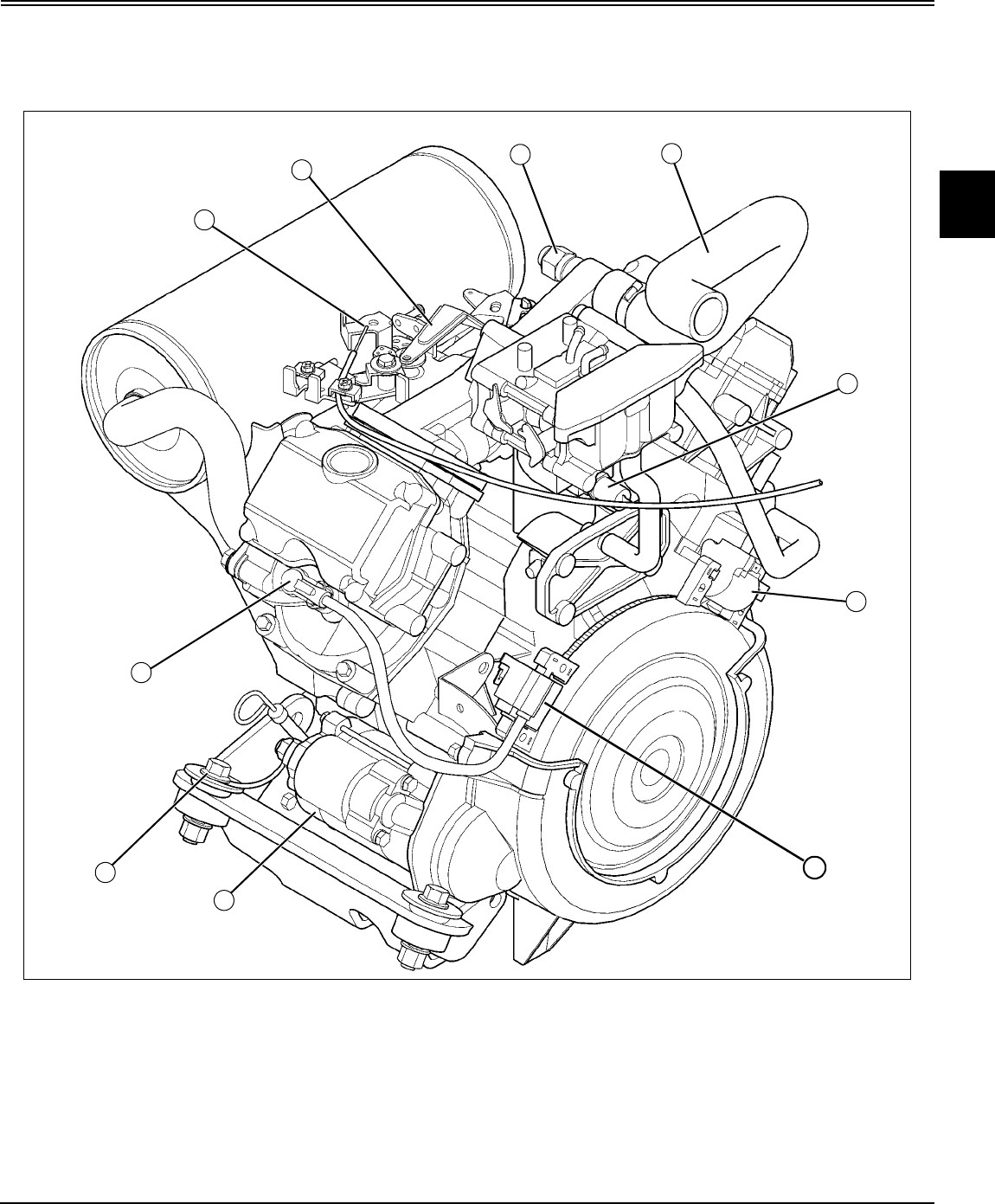
Engine - Gas (Liquid-Cooled) Component Location - 27
ENGINE - GAS (LIQUID-COOLED) COMPONENT LOCATION
Component Location
Engine (FD671D)
MX14278
Note: Number 1 cylinder is on same side of engine as
oil filter.
A
B
CD
E
F
H
I
J
G
A- Throttle Cable
B- Governor Arm
C- Coolant Temperature Sensor
D- Coolant Hose
E- Fuel Shutoff Solenoid
F- Ignition Module #1 Cylinder
G- Ignition Module #2 Cylinder
H- Starting Motor
I- Engine Frame Ground
J- Spark Plug #2 Cylinder

Engine - Gas (Liquid-Cooled) Component Location - 28
ENGINE - GAS (LIQUID-COOLED) COMPONENT LOCATION
Engine (FD750D)
MX14312
Note: Number 1 cylinder is on same side of engine as
oil filter.
B
G
P
J
RH
A
D
N
C
OK
I
L
M
E
A- Engine Coolant Temperature Sensor
B- #2 Cylinder Fuel Injector
C- Air Temperature Sensor
D- Vacuum Pressure Sensor
E- Fuel Pressure Relief Screw
F- #1 Cylinder Fuel Injector
G- Engine Coolant Temperature Sensor
H- Engine Oil Pressure Switch (RH Side)
I- Fuel Shutoff Solenoid
J- Ignition Module #1 Cylinder
K- Ignition Module #2 Cylinder
L- Wiring Harness Connector
M- Wiring Harness Connector
N- Starting Motor Solenoid
O- Frame Ground
P- Spark Plug #2 Cylinder

Engine - Gas (Liquid-Cooled) Theory of Operation - 29
ENGINE - GAS (LIQUID-COOLED) THEORY OF OPERATION
Theory of Operation Cooling System Operation
MX14217
Function:
The coolant pump circulates coolant through the cooling
system, drawing hot coolant from the engine block, and
circulating it through the radiator for cooling.
System Operation:
The impeller-type coolant pump draws coolant from the
bottom of the radiator when the thermostat is open, or from
the bypass when the thermostat is closed. Coolant from the
water pump flows to the water jackets in block, up through
cylinder heads, intake manifold, past the coolant
temperature sensor and thermostat.
When the engine temperature is below approximately 82°C
(180°F), the thermostat is closed and coolant is directed
back to the water pump through bypass hose to be
recirculated. This allows the engine to warm up to
operating temperature quickly.
When the engine temperature is approximately 82°C
(180°F), the thermostat begins to open and is fully open at
95°C (203°F). Coolant from the water jackets and cylinder
heads now flow through the thermostat to the radiator,
which is cooled by the radiator fan. The fan is driven by a
belt off the crankshaft pulley. If the engine coolant
temperature raises to 111°C (232°F), a thermo switch
detects this, and turns on a warning light on the dash,
warning you of a potentially dangerous overheating
situation.
The radiator cap maintains a pressure of 78 - 98 kPa (11.3
- 14.2 psi) inside the radiator, which actually raises the
boiling point of the coolant. The radiator cap contains a
pressure valve and a vacuum valve. When the coolant is
hot and pressure is above 98 kPa (14.2 psi), the pressure
valve opens, allowing some coolant to flow to the recovery
tank. After the engine is stopped, the coolant cools and the
pressure inside the radiator decreases. The pressure
difference between the radiator and recovery tank forces
the vacuum valve open and some coolant from the
recovery tank flows back to the radiator.
C
A
DF
G
B
E
KH
J
I
A- Radiator
B- Cooling Fan
C- Radiator Cap, maintains radiator pressure at 78
- 98 kPa (11.3 - 14.2 psi)
D- Thermo Switch, detects at 111°C (232°F)
E- Bypass Tube
F- Engine Body
G- Water Pump (Impeller)
H- Jiggle Valve
I- Drain Plug
J- Valve, One Way
K- Thermostat, fully open at 95°C (203°F)

Engine - Gas (Liquid-Cooled) Theory of Operation - 30
ENGINE - GAS (LIQUID-COOLED) THEORY OF OPERATION
Fuel and Air System Operation
Function:
The fuel system supplies fuel to the engine for combustion.
The air intake system filters air needed for combustion.
MX14324
The fuel tank holds the fuel pick-up and fuel sensor
assembly. The carburated engine has a fuel pump mounted
to the side of the engine The fuel pick-up (A) consists of a
fuel pick-up tube and a float type fuel sensor. The fuel
pump draws fuel through the fuel pump screen. Low
pressure fuel from the fuel pump flows through the fuel
shut-off valve and in-line fuel filter to the carburetor. Fuel
pressure is maintained at the carburetor inlet needle until
the float allows more fuel in the bowl.
The fuel injected engine has pressurized fuel supplied to
the engine. The fuel pick-up (B) consists of a fuel pick-up
tube with an in-line electric fuel pump (C).
System Operation - Fuel Injection:
An electric fuel pump (C) mounted inside the fuel tank
provides pressurized fuel to the carburetor. The fuel pump
uses the fuel for lubrication and cooling. The fuel shutoff
solenoid shuts off fuel to the main jet, preventing gas fumes
from escaping into the air for emission control, while the
fuel cap is vented for releasing any increased pressure
within the fuel tank.
The ignition delay module is used with the fuel shut-off
solenoid to prevent backfire. The ignition delay module
allows the spark plugs to fire for one additional second after
the key switch is turned off to burn any remaining fuel in the
cylinder. When the key switch is turned off, the fuel shut-off
solenoid is de-energized.
Air enters the air filter though the side panel screen and air
filter inlet hose. The breather hose vents crankcase fumes
into the carburetor for burning to decrease emissions.
Fuel Injection Air System Components and
Operation (FD750D)
MX14223
Function:
The fuel injection system supplies pressurized fuel to the
fuel injectors for combustion. The air intake system filters
air needed for combustion.
System Operation:
An electric fuel pump mounted inside the fuel tank provides
pressurized fuel to the fuel injectors (A). The fuel pump
uses the fuel for lubrication and cooling. The fuel pump and
fuel injectors are controlled by the fuel injection module
computer. The controller monitors engine operating and
environmental conditions to calculate the amount of fuel to
inject. The fuel pump draws fuel through the fuel pump
screen. High pressure fuel from the fuel pump flows
through the in-line fuel filter to the fuel pressure regulator
(B) and fuel injector. The fuel injector is a solenoid operated
type valve with single point injection. Fuel is injected into
the throttle body when the solenoid is energized by the
controller. Fuel pressure is controlled by the fuel pressure
regulator. The regulator is an overflow type regulator that
maintains fuel pressure at the fuel injector at a constant
175 kPa (25 psi). Excess fuel flows through the regulator
valve and fuel return hose to the fuel tank. The fuel shutoff
solenoid shuts off fuel to the main jet, preventing gas fumes
from escaping into the air for emission control, while the
fuel cap is vented for releasing any increased pressure
within the fuel tank
AB
C
A- Fuel Injectors
B- Fuel Pressure Regulator
C- Air Temperature Sensor
D- Water Temperature Sensor
E- Vacuum Pressure Sensor
F- Thermo Switch
B
AC
A
D
E
F

Engine - Gas (Liquid-Cooled) Theory of Operation - 31
ENGINE - GAS (LIQUID-COOLED) THEORY OF OPERATION
The throttle control lever, which is connected to the throttle
lever and the governor lever, controls engine rpm. The
governor lever is connected to the throttle valve inside the
throttle body. Slow idle is adjusted by turning the slow idle
stop screw and fast idle is adjusted by moving the throttle
control plate.
Air enters the air filter through the side panel screen and air
filter inlet hose. The primary and secondary elements filter
the air before entering the throttle body. The breather hose
vents crankcase fumes into the throttle body for burning to
decrease emissions. A small amount is always present due
to some restriction of air movement through the filter
elements. The vacuum increases as the filter elements
become plugged.
Fuel Pressure Regulator Operation (FD750D)
Function:
Maintains a constant differential in pressure between fuel
pressure at the injector and air pressure in the throttle body.
Therefore, the amount of fuel injected is determined by the
opening time of the injector.
M45334
System Operation:
The pressure regulator is an overflow type of regulator. The
spring chamber is connected to the throttle body to insure
that they are operating at the same air pressure. High
pressure fuel from the injector flows to the pressure
regulator inlet and fills the fuel chamber. A hose from the
vacuum inlet is connected to the intake manifold. This
allows the air pressure in the spring chamber and intake
manifold to be equal.
When intake manifold vacuum increases, the spring
chamber vacuum also increase and overcomes spring
tension, allowing the diaphragm to move upward. With the
valve connected to the diaphragm, the valve moves upward
and allows more fuel to flow out of the outlet and return to
the fuel tank. This lowers the fuel pressure. As intake
manifold vacuum decreases, the spring chamber vacuum
decreases and the spring returns the diaphragm to the
original position. The valve restricts fuel flow to return and
fuel pressure increases.
Governor Operation
System Operation:
The governor controls engine speed. Governed engine
speed is a balance between governor spring tension, set by
the throttle control, and actual engine speed, countered by
centrifugal force of the governor flyweights. As tension is
applied to governor spring, governor linkage opens
carburetor/fuel injection throttle shaft and plate, increasing
engine rpm. As the engine speed increases, flyweight
assembly (driven by the crankshaft gear) pushes on
governor arm, rotating governor shaft and lever, moving
throttle shaft, closing throttle plate slightly and reducing
rpm to governed operating speed. If a heavy load is
encountered, engine speed drops, as does the governor
assembly speed. Flyweights retract and allow shaft arm to
move governor shaft and lever in opposite direction to open
throttle plate and allow more air into venturi to draw in more
fuel until engine peak operating speed is recovered.
Springs provide a smooth yet responsive transitional
control.
A- To Throttle Body
B- Spring
C- Spring Chamber
D- Valve Support
A
B
C
D
E
F
G
H
I
E- Inlet from Injector
F- Return to Tank
G- Fuel Chamber
H- Valve
I- Diaphragm
Important: Avoid Damage! Flyweight assembly shaft
is pressed into crankcase cover and is not
serviceable. Therefore, if it is damaged or pulled
loose, the crankcase cover MUST BE replaced.

Engine - Gas (Liquid-Cooled) Theory of Operation - 32
ENGINE - GAS (LIQUID-COOLED) THEORY OF OPERATION
Lubrication System Operation
MX14218
System Operation:
A positive displacement gerotor pump (L) is used to
pressurize the lubrication system. The lubrication system is
protected by an oil pressure relief valve (M), low pressure
switch (O), and an oil filter (N) with bypass.
The oil pump (L) draws oil from the sump through a filter
screen (K). Pressure oil from the pump flows to the oil
pressure relief valve (M). Oil pressure reading should be
276 kPa (40 psi) minimum. If oil pressure exceeds 310
kPa (45 psi), the relief valve (M) opens allowing oil to
return to sump. The relief valve is not adjustable.
Pressure oil from the relief valve flows to the oil filter (N).
The filter contains a bypass valve, which opens if the
element becomes plugged to insure engine lubrication.
An oil pressure switch (O) mounted above the oil filter turns
on a warning light if oil pressure is below 98 kPa (14.2 psi).
Filtered pressure oil flows through a passage in the oil
sump to the crankshaft main bearing (J) (PTO side).
Drilled passages in the crankshaft (I) distribute oil from the
main bearing to the connecting rod (G) journals and
crankshaft main bearing (H) (flywheel side). A drilled
passage in the connecting rods allows oil from the
connoting rod journal to lubricate the piston (F) and
cylinder walls and camshaft (B), tappets (C), governor gear
(A), water pump gear (D) and rocker arms and valves (E).
D
A
O
N
M
K
L
J
I
G
F
B
C
E
H

Engine - Gas (Liquid-Cooled) Theory of Operation - 33
ENGINE - GAS (LIQUID-COOLED) THEORY OF OPERATION
Throttle Body Operation (FD750D)
MX14223
Function:
Injects and atomizes the fuel into the intake air for the
proper combustion.
System Operation:
An electric fuel pump, controlled by the computer, supplies
fuel to the inlet (B) of the throttle body to the injector. The
fuel pressure regulator holds the fuel under pressure in the
injectors (A). The computer receives signals from the
throttle sensor and other sensors then controls the time the
injector is open. The injector injects the atomized fuel into
the throat of the throttle body.
Excess fuel not used by the injector flows through the
pressure regulator (C) back to the fuel tank.
The FD750D has an extra passage [fuel pressure relief
screw (F)] in the throttle body that allows for a means to
relieve the fuel pressure in the fuel lines before any work is
done on the system.
C
A
G
A
H
I
J
F
E
B
D
A- Fuel Injectors
B- Fuel Inlet
C- Fuel Pressure Regulator
D- Vacuum Hose
E- Fuel Return Hose
F- Fuel Pressure Relief Screw
G- Air Temperature Sensor
H- Water Temperature Sensor
I- Vacuum Pressure Sensor
J- Thermo Switch

Engine - Gas (Liquid-Cooled) Diagnostics - 34
ENGINE - GAS (LIQUID-COOLED) DIAGNOSTICS
Diagnostics
Engine Diagnosis
c Caution: Avoid Injury! Engine radiator fluid is
extremely hot during operation. The engine
may start to rotate at any time. Keep hands
away from all moving parts when testing.
Symptom: Engine Starting Problems
Problem Cause - Solution
1. Engine will not
crank?
a. No: Go to next step.
b. Yes: Battery weak or discharged.
Fusible link defective.
Check key switch or wiring.
Starter solenoid defective.
Starter motor defective.
2. Engine will not
start; plug wet?
a. No: Go to next step.
b. Yes: Mixture too rich.
Clean under engine shrouding.
Check spark plug gap and spark (see
Electrical section).
Inlet needle and seat sticking
(FD671D engine).
Clean carburetor (FD671D engine).
3. Engine is hard to
start when cold?
a. No: For additional tests, see
“Engine Tests” on page 38.
b. Yes: Mixture too rich.
Mixture too lean.
Clean under engine shrouding.
Choke is not completely shut, adjust
choke (FD671D engine).
Inlet needle and seat sticking
(FD671D engine).
Clean carburetor (FD671D engine).
4. Engine cranks
but will not start?
a. No: Go to next step.
b. Yes: Battery weak or discharged.
Fuel shut-off valve closed (in-line
valve).
Fuel shut-off solenoid not allowing
fuel into main jet (FD671D engine).
Fuel shut-off solenoid not allowing
fuel into fuel injector (FD750D
engine).
Improper use of choke (FD671D
engine).
Float level too high (FD671D engine).
Check spark (See Electrical section).
Weak or faulty spark plug.
Faulty high tension leads.
Faulty ignition module (FD671D
engine).
Faulty fuel injection module (FD750D
engine).
Faulty ignition coil.
Faulty pulsar coil.
Contaminated fuel or faulty fuel
supply system.
Defective fuel pump.
Air being drawn in through a hole in
fuel line(s).
Clogged fuel line or filter.
Fuel tank vent line clogged.
Air filter restricted.
Defective head gasket.
Cylinder head loose.
Broken valve spring.
Warped cylinder head.
Poor compression.
Worn piston/piston rings stuck or not
seated.
Worn cylinder bore.
Worn or burned valves, or improper
clearance.
Symptom: Engine Starting Problems
Problem Cause - Solution

Engine - Gas (Liquid-Cooled) Diagnostics - 35
ENGINE - GAS (LIQUID-COOLED) DIAGNOSTICS
Symptom: Engine Performance Problems
Problem Cause - Solution
1. Loss of power? a. No: Go to next step.
b. Yes: Low oil level.
Too much oil in crankcase.
Carburetor out of adjustment
(FD671D engine).
Air/Fuel passages plugged.
Carbon deposits in exhaust pipe/
muffler.
Carbon deposits in combustion
chamber.
Weak or faulty spark plug.
Faulty high tension leads.
Faulty ignition module (FD671D
engine).
Faulty fuel injection module (FD750D
engine).
Faulty ignition coil.
Faulty pulsar coil.
Contaminated fuel or faulty fuel
supply system.
Defective fuel pump.
Air being drawn in through a hole in
fuel line(s).
Clogged fuel line or filter.
Fuel tank vent line clogged.
Vapor lock. Air filter restricted.
Defective breather valve.
Cylinder head loose.
Mixture too lean.
Check and clean air cleaner.
Adjust idle mixture and check engine
performance (FD671D engine).
Choke is not completely open, adjust
choke (FD671D engine).
Clean carburetor (FD671D engine).
Worn or burned valves, or improper
clearance.
Broken valve spring. Warped cylinder
head.
Defective head gasket.
Poor compression.
Worn piston/piston rings stuck or not
seated.
Worn cylinder bore.
2. Engine runs
erratically?
a. No: Go to next step.
b. Yes: Carburetor out of adjustment
(FD671D engine).
Lack of coolant.
Governor linkage out of adjustment.
Faulty governor spring.
Governor gear assembly binding or
broken.
Check spark (See Electrical section).
Carburetor flange loose or leaking at
gasket (FD671D engine).
Throttle body flange loose or leaking
at gasket (FD750D engine).
Carburetor body and throttle shaft
worn (FD671D engine).
Throttle body and throttle shaft worn
(FD750D engine).
Weak or faulty spark plug.
Faulty high tension leads.
Faulty ignition module (FD671D
engine).
Faulty fuel injection module (FD750D
engine).
Faulty ignition coil.
Faulty pulsar coil.
Contaminated fuel or faulty fuel
supply system.
Defective fuel pump.
Air being drawn in through a hole in
fuel line(s).
Clogged fuel line or filter.
Fuel tank vent line clogged.
Vapor lock.
Oil leakage around governor shaft.
Defective oil seal.
3. Engine misses
at high rpm?
a. No: Go to next step.
b. Yes: Check spark (See Electrical
section).
Weak or faulty spark plug.
Faulty high tension leads.
Faulty ignition module (FD671D
engine).
Faulty fuel injection module (FD750D
engine).
Faulty ignition coil.
Faulty pulsar coil. Carburetor out of
adjustment (FD671D engine).
Clogged fuel line or filter.
Fuel tank vent line clogged.
Defective fuel pump.
Warped cylinder head.
Symptom: Engine Performance Problems
Problem Cause - Solution

Engine - Gas (Liquid-Cooled) Diagnostics - 36
ENGINE - GAS (LIQUID-COOLED) DIAGNOSTICS
4. Engine misses
at low rpm?
a. No: Go to next step.
b. Yes: Carburetor out of adjustment
(FD671D engine).
Air/Fuel passages plugged.
Air being drawn through carburetor or
intake manifold flanges (FD671D
engine).
Air being drawn through throttle body
or intake manifold flanges (FD750D
engine).
Incorrect timing gear alignment.
Check spark (See Electrical section).
Weak or faulty spark plug.
Faulty high tension leads.
Faulty ignition module (FD671D
engine).
Faulty fuel injection module (FD750D
engine).
Faulty ignition coil.
Faulty pulsar coil.
Worn or burned valves, or improper
clearance.
Warped cylinder head.
5. Engine rpm low
or engine stalls?
a. No: Go to next step.
b. Yes: Battery weak or discharged.
6. Engine speed
unstable (surging)?
a. No: Go to next step.
b. Yes: Mixture too lean.
Clean under engine shrouding.
Adjust idle mixture and check engine
performance (FD671D engine).
Clean carburetor (FD671D engine).
7. Engine is
sluggish?
a. No: Go to next step.
b. Yes: Mixture too rich.
Check and clean air cleaner.
Adjust idle mixture and check engine
performance (FD671D engine).
Choke is not completely open, adjust
choke (FD671D engine).
Clean carburetor (FD671D engine).
8. Black, smoky
exhaust?
a. No: Go to next step.
b. Yes: Check spark plug gap and
spark (see Electrical section).
Mixture too rich.
Check and clean air cleaner.
Choke is not completely open, adjust
choke (FD671D engine).
Symptom: Engine Performance Problems
Problem Cause - Solution
9. Spark plug
fouled black?
a. No: Go to next step.
b. Yes: Check spark plug gap and
spark (see Electrical section).
Mixture too rich.
Check and clean air cleaner.
Adjust idle mixture and check engine
performance (FD671D engine).
Choke is not completely open, adjust
choke (FD671D engine).
Inlet needle and seat sticking
(FD671D engine).
10. Spark plug
burned white?
a. No: Go to next step.
b. Yes: Check spark plug gap and
spark (see Electrical section).
Mixture too lean.
Clean under engine shrouding.
Clean carburetor (FD671D engine).
11. Runs better
without air
cleaner?
a. No: Go to next step.
b. Yes: Mixture too rich.
Check and clean air cleaner.
12. Runs worse
when warm?
a. No: Go to next step.
b. Yes: Mixture too rich.
Check and clean air cleaner.
Adjust idle mixture and check engine
performance (FD671D engine).
Choke is not completely open, adjust
choke (FD671D engine).
Inlet needle and seat sticking
(FD671D engine).
13. Engine
overheats?
a. No: Go to next step.
b. Yes: Mixture too lean.
Clean under engine shrouding.
Water pump nylon impeller defective.
14. Engine
backfires?
a. No: Go to next step.
b. Yes: Carburetor out of adjustment
(FD671D engine).
Check spark (See Electrical section).
Faulty pulsar coil.
Air being drawn in through a hole in
fuel line(s).
Cylinder head loose.
Warped cylinder head.
Defective head gasket.
Intake valve burned or sticking.
Symptom: Engine Performance Problems
Problem Cause - Solution

Engine - Gas (Liquid-Cooled) Diagnostics - 37
ENGINE - GAS (LIQUID-COOLED) DIAGNOSTICS
15. Engine
knocks?
a. No: Go to next step.
b. Yes: Excessive engine load.
Faulty ignition module (FD671D
engine).
Faulty fuel injection module (FD750D
engine).
Contaminated fuel or faulty fuel
supply system.
Defective head gasket.
16. Engine
overheats?
a. No: For additional tests, see
“Engine Tests” on page 38.
b. Yes: Lack of coolant.
Excessive engine load.
Fan belt slippage.
Defective radiator hose or clamp.
Improper or defective radiator cap.
Broken or missing fan shroud.
Defective radiator.
Loose stud bolts and cap screw.
Cracked or porous casting.
Damaged water pump seals.
Improperly installed gasket.
Warped cylinder head.
Broken valve spring.
Defective head gasket.
Worn or burned valves, or improper
clearance.
Symptom: Engine fuel/oil/coolant problems
Problem Cause - Solution
1. Coolant
leakage?
a. No: For additional tests, see
“Engine Tests” on page 38.
b. Yes: Lack of coolant.
Improper or defective radiator cap.
Defective radiator hose or clamp.
Defective radiator.
Cracked or porous casting.
Loose stud bolts and cap screw.
Engine overheating.
Damaged water pump seals.
Improperly installed gasket.
Cylinder head loose.
Symptom: Engine Performance Problems
Problem Cause - Solution
2. Excessive oil
consumption?
a. No: Go to next step.
b. Yes: Too much oil in crankcase.
Incorrect oil viscosity.
Drain-back in breather chamber
plugged.
Defective breather valve.
Worn valve stems(s) or valve
guide(s).
Plugged oil ring groove.
Poor compression.
Worn piston/piston rings stuck or not
seated.
Worn cylinder bore.
3. Excessive fuel
consumption?
a. No: Go to next step.
b. Yes: Check spark (See Electrical
section).
Weak or faulty spark plug.
Faulty high tension leads.
Faulty ignition module (FD671D
engine).
Faulty fuel injection module (FD750D
engine).
Faulty ignition coil.
Faulty pulsar coil.
Improper use of choke (FD671D
engine).
Air filter restricted.
Carburetor out of adjustment
(FD671D engine).
Float level too high (FD671D engine).
Cylinder head loose.
Broken valve spring.
Worn or burned valves, or improper
clearance.
Poor compression.
Worn piston/piston rings stuck or not
seated.
Worn cylinder bore.
Symptom: Engine fuel/oil/coolant problems
Problem Cause - Solution

Engine - Gas (Liquid-Cooled) Diagnostics - 38
ENGINE - GAS (LIQUID-COOLED) DIAGNOSTICS
Engine Tests
Test Procedure - A:
Engine
1. When checking dipstick, oil at proper level and
viscosity? No leakage? Clean oil and filter?
Yes: Go to next step.
No: Change oil and inspect for source of
contamination.
No: Change oil filter.
No: Check gaskets, seals, plugs, cylinder head, block,
and intake manifold and breather.
2. Air filter outlet hose not cracked; clamps tight?
Yes: Go to next step.
No: Replace hose and/or tighten clamps.
3. Air filter elements not plugged? Air filter housing
sealed; no dirt tracking inside filter element?
Yes: Go to next step.
No: Replace element or housing.
4. Air filter restriction indicator not leaking?
Yes: Go to next step.
No: Replace indicator.
5. Does fuel shutoff solenoid pull in and stay in when
key is returned to “ON”? (Listen for clicking as key is
cycled.)
Yes: Go to next step.
No: If solenoid will not pull in and hold in, see Fuel
Shutoff Solenoid Circuit Diagnosis in Electrical section.
6. Check hand throttle control lever linkage. Full
movement of governor control arm from idle to full
speed?
Yes: Go to next step.
No: Repair; replace or adjust linkage.
7. Check intake and exhaust valves. Valve clearance
within specification (engine cold)? Valves not sticking?
Yes: Go to next step.
No: Adjust valves. See “Tests and Adjustments” in this
section.
No: Check valve guides and stems.
8. Is fuel is reaching injectors (FD750D)? (Crack fuel
injection lines at injectors. Crank engine. Be sure fuel
shutoff solenoid has pulled in. Fuel leaks out.)
Yes: Go to next step.
No: No fuel present: Check fuel shutoff valve is open,
fuel level in tank, inspect filter/separator element. Test
fuel pump.
9. Check flywheel and starting motor: Minimum
cranking rpm within specification?
Yes: Go to next step.
No: See “Starter Amp Draw Test” in Electrical section.
10. Carburetor choke and governor linkage, (FD671D).
Linkage not binding and adjusted correctly?
Yes: Go to next step.
No: Repair, replace or adjust linkage.
11. Carburetor - fuel filter, fuel pump, and carburetor
bowl drain screw (key switch on), (FD671D). Fuel level
increases in filter? Fuel pump operating - listen for
humming sound near fuel cap? Fuel present in float
bowl when screw is opened?
Yes: Go to next step.
No: See “Shutoff Circuit Diagnosis” in the Electrical
section.
No: Test fuel pump pressure and flow.
No: Check carburetor for debris.
12. Fuel injection pump static timing test, (FD750D).
Timing should be correct? (Remove pump as the LAST
possible solution.)
Yes: Go to next step.
No: Have injection pump static timing adjustment
performed by a qualified service repair shop. See
“Tests and Adjustments” in this section.
13. Carburetor/Throttle body (engine running). Low idle
at 1550 rpm? High idle at 3600 rpm?
Yes: Go to next step.
No: See “Low Idle Speed Adjustment” on page 42 and
“High Idle Speed Adjustment” on page 42 in this
section.
14. Engine runs smoothly through out rpm range with
low smoke and good power?
Yes: Go to next step.
No: Adjust governor.
15. Test oil pressure switch port. Minimum oil pressure
Test Conditions:
• Machine parked on level surface.
• PTO Switch off
• Key switch off unless indicated otherwise.
• Spark plug connected to D-05351ST Spark Tester

Engine - Gas (Liquid-Cooled) Diagnostics - 39
ENGINE - GAS (LIQUID-COOLED) DIAGNOSTICS
within specifications?
Yes: Go to next step.
No: Test engine oil pressure. (See “Engine Oil
Pressure Test” on page 46 in this section.)
16. Thermostat opening temperature within
specifications?
Yes: Go to next step.
No: Perform thermostat opening test. See “Tests and
Adjustments” in this section.
17. Muffler not restricted?
Yes: Go to next step.
No: Replace muffler.
18. When performing cylinder compression test:
Cylinder compression within specification? Pressure
difference between cylinders within specification?
Yes: Engine tests completed.
No: Rebuild engine.
Coolant tank and radiator
1. Coolant level between marks on tank when engine is
warm? Coolant in radiator full to top?
Yes: Go to next step.
No: Add proper coolant mix.
2. Coolant not contaminated with oil, fuel or discolored
brown?
Yes: Go to next step
No: Drain and flush system. Check for source of
contamination.
3. Radiator screen free of debris?
Yes: Go to next step.
No: Clean or replace.
4. Hoses not cracked or leaking; clamps and radiator
cap tight?
Yes: Go to next step.
No: Pressure test radiator and cap.
5. Water pump/alternator belt tight; not glazed or
cracked?
Yes: Go to next step.
No: Replace and adjust belt tension.
6. Fan blades not damaged or warped?
Yes: Coolant tests completed.
No: Replace fan.
Fuel tank, pump, lines and filter
1. Fuel level correct; not contaminated or stale
smelling; no water in fuel?
Yes: Go to next step.
No: Drain and clean fuel tank. Add fresh fuel.
2. Fuel pump filter and in-line filter free of debris?
Yes: Go to next step.
No: Replace filters.
3. Fuel hoses not cracked or leaking?
Yes: Go to next step.
No: Replace.
4. Fuel hose clamps tight?
Yes: Go to next step.
No: Replace or tighten.
5. Fuel tank does not have vacuum?
Yes: Fuel tank, pump, lines and filter tests completed.
No: Replace vented fuel cap.

Engine - Gas (Liquid-Cooled) Tests and Adjustments - 40
ENGINE - GAS (LIQUID-COOLED) TESTS AND ADJUSTMENTS
Tests and Adjustments
Throttle Lever Adjustment
Reason:
To achieve smooth throttle lever movement with enough
tension to maintain throttle setting.
Test Equipment:
• Spring Scale
Procedure:
1. Connect a scale near the end of the throttle lever.
2. Move throttle lever to slow idle position.
MX14234A
3. Adjust friction disks by tightening or loosening lock nut
(A) until throttle lever movement in forward direction is 18 -
35 N (4 - 8 lb force).
Note: Make sure throttle cable is not binding or stuck.
Throttle Cable Adjustment
Reason:
To insure that the throttle lever cable moves the governor
linkage from slow to fast idle position.
Procedure:
MX14227
Picture Note: FD671D engine shown; FD750D
engine does not have choke assembly parts (A).
1. Set the throttle lever in the slow idle position. Check that
the throttle control lever (D) contacts the idle speed
adjustment screw (E) at the slowest throttle lever setting.
2. If the throttle control lever (D) is not touching the screw
(E) at the slowest setting, loosen the throttle cable clamp
(C). Pull throttle cable (B) to left. When the control lever
contacts the control plate idle adjustment screw, retighten
the cable clamp.
3. Set the throttle lever to the fastest idle position and
check that the throttle control lever is advancing to the full
open position.
4. If the control lever is not advancing to the fully open
position, loosen the cable clamp and readjust cable.
5. If the cable cannot be adjusted to obtain a fully open
throttle lever position at fastest idle while maintaining
contact with the adjustment screw at lowest idle position, it
will be necessary to adjust the control plate idle speed
adjustment screw.
6. Turn the idle adjustment screw (E) clockwise until it
contacts the throttle control lever when set in the slow idle
position. After completing the idle screw adjustment, check
to make certain the motor is maintaining a 1550 RPM
governed low idle setting. Follow the Low Idle Speed
Adjustment sequence in this chapter if corrections are
necessary.
A
EC
B
A
D

Engine - Gas (Liquid-Cooled) Tests and Adjustments - 41
ENGINE - GAS (LIQUID-COOLED) TESTS AND ADJUSTMENTS
Choke Adjustment (FD671D)
Reason:
To make sure the choke plate is fully closed when the
choke lever is in the full choke position. Correct adjustment
also makes sure choke is completely open in the fast idle
position.
Procedure:
Note: Adjust throttle cable before adjusting choke.
1. Remove air cleaner assembly.
2. Move choke lever forward to full choke position and
check that choke butterfly in carburetor is fully closed.
MX14227
3. If adjustment is necessary, loosen the choke cable
clamp (A) and move the cable (B) to obtain a fully closed
position. Retighten the cable clamp.
4. Release the choke lever and make certain the return
spring (C) on the governor control plate is returning the
choke butterfly to the fully open position.
5. Reinstall air cleaner assembly and check choke
operation while starting machine.
Governor Adjustment
Reason:
To make sure the governor shaft contacts the flyweight
plunger when the engine is stopped.
Note: Adjust throttle cable before adjusting governor
linkage.
Procedure:
Note: It is not necessary to remove the throttle or
choke cables from the governor plate assembly to
reach the governor arm. The governor plate can be
swung away with the cables installed when accessing
the governor arm components.
MX14227
Picture Note: FD671D engine shown; FD750D
engine does not have choke assembly parts (D).
1. Loosen bolt (A), and fully turn the bracket (B)
counterclockwise and hold it there.
2. Turn the top end of the governor arm (C)
counterclockwise to fully open the carburetor/EFI throttle
valve and tighten the bolt (A).
A
B
C
D
BC
A

Engine - Gas (Liquid-Cooled) Tests and Adjustments - 42
ENGINE - GAS (LIQUID-COOLED) TESTS AND ADJUSTMENTS
Low Idle Speed Adjustment
Reason:
To set engine slow idle mixture rpm.
Equipment:
• JTO5719 Photo Tachometer
Procedure:
1. Disconnect all external loads from engine.
2. Put reflective tape on blower housing screen.
3. Start and run engine at MEDIUM idle for five minutes.
MX14226
Picture Note: FD671D engine shown; FD750D
engine does not have choke assembly parts (E).
4. Move throttle lever on dash to idle position. Hold the
throttle lever (A) on the carburetor in the closed position,
turn governor arm (C) clockwise all the way.
5. Adjust the low idle speed screw (B) until the engine idles
at 1450 rpm (carburetor idle rpm). Use the photo
tachometer to check engine rpm at the blower housing
screen.
6. Release the throttle lever and adjust the low idle speed
set screw (D) on the control plate to obtain a 1550 rpm
governed low idle speed.
High Idle Speed Adjustment
Reason:
To set engine high idle mixture and rpm.
Equipment:
• JTO5719 Photo Tachometer
Procedure:
Note: High idle speed adjustment should be made after
the low idle speed adjustment is performed.
1. Start and run engine at MEDIUM idle for five minutes.
MX14227
Picture Note: FD671D engine shown; FD750D
engine does not have choke assembly parts (D).
2. Loosen the lock nut (C), and unscrew the high idle set
screw (B) a few turns.
3. Use a photo tachometer to check engine rpm at the
blower housing screen.
4. Move the throttle lever on dash to obtain the a 3600
RPM high idle speed and leave it there.
5. Turn the high idle set screw (B) so that the end of it just
touches the speed control lever (A). Tighten the lock nut
(C).
6. Recheck the idle speed and readjust if necessary.
Specifications:
High idle setting . . . . . . . . . . . . . . . . . . . . . . . . . 3550 rpm
Carburetor idle setting. . . . . . . . . . . . . . . . . . . . 1450 rpm
Governed idle setting . . . . . . . . . . . . . . . . . . . . 1600 rpm
c Caution: Avoid Injury! Engine will be HOT. Be
careful not to burn skin.
A
B
C
D
E
c Caution: Avoid Injury! Always keep hands clear
of moving parts.
Important: Avoid Damage! Do Not adjust high idle
speed with air cleaner removed.
BC
A
D

Engine - Gas (Liquid-Cooled) Tests and Adjustments - 43
ENGINE - GAS (LIQUID-COOLED) TESTS AND ADJUSTMENTS
Note: For high altitude operation above 4000 feet, use
high altitude carburetor kit, to prevent over rich fuel
mixture and black exhaust smoke.
Compression Test
Reason:
To determine the condition of pistons, rings, cylinder walls
and valves.
Test Equipment:
• JDM59 Compression Gauge
Procedure:
1. Adjust valve clearance to 0.15 mm (0.006 in.) with
engine at top dead center (TDC) compression stroke.
Engine must be “cold” (shop temperature, about 60 - 85°F
(16 - 30°C). See “Valve Clearance Adjustment” on page 43
for procedure.
Note: Be sure the battery is fully charged before
performing procedure.
2. Run engine until it reaches operating temperature
(thermostat opens, and both radiator hoses hot).
MX14235
3. Stop the engine, remove both spark plugs, and ground
leads to block or use a spark tester (B).
4. Attach the compression gauge assembly (A) firmly into
one plug hole.
5. Put throttle lever in fast idle (wide open) position. On
FD671D engines, choke must be properly adjusted and
fully open. Air filter must be clean.
6. Crank hot engine until highest compression reading is
obtained.
7. Record pressure readings for each cylinder.
Specifications:
Minimum Compression . . . . . . . . . . . . . 620 kPa (90 psi)
Results:
• If pressure readings are above specification, adjust
valves and check fuel and intake air systems. Check
exhaust for restriction.
• If pressure readings are below specification, squirt clean
engine oil into cylinders and repeat test.
• If pressure increases significantly, check piston rings
and cylinder walls for wear or damage.
• If pressure does NOT increase after retest, check for
leaking valves, valve seats or cylinder head gaskets.
• Install spark plugs and reconnect ignition coils when
finished with testing procedure.
Valve Clearance Adjustment
Reason:
Check and adjust valve clearance for proper engine
operation.
Procedure:
1. Remove spark plugs.
2. Remove valve covers.
3. Turn the crankshaft clockwise until piston, visible in the
spark plug hole, is at TDC (top dead center) of the
compression stroke.
A
B
Important: Avoid Damage! DO NOT overheat starting
motor during test. Starter duty is 5 seconds one, 10
seconds off. Additionally, if throttle lever is left in
slow idle position (air flow into carburetor
restricted), compression could read up to 483 kPa
(70 psi) below specification.
Important: Avoid Damage! Perform valve clearance
measurement or adjustment when the engine is at
room temperature, 16 - 27°C (60 - 80°F). Proper valve
clearance is essential for the engine to operate
properly. Check valve clearance for each cylinder
separately.

Engine - Gas (Liquid-Cooled) Tests and Adjustments - 44
ENGINE - GAS (LIQUID-COOLED) TESTS AND ADJUSTMENTS
MX14236
4. Align the flywheel magnet (B) with #1 ignition coil (C)
and #2 ignition coil (A).
5. Both intake and exhaust valves will be closed and the
rocker arms will be loose. If one rocker arm is tight, the
piston is on the exhaust stroke and the crankshaft must be
turned another revolution (360 degrees).
MX14237
6. Loosen the lock nut (D) and valve clearance adjustment
bolt (E).
7. Insert a 0.15 mm (.006 in.) feeler gauge (F) between
rocker arm and valve stem, and turn the adjusting bolt (E)
until the thickness gauge begins to bind between the rocker
arm and valve stem end.
8. Holding the adjusting bolt, tighten the locknut to 11 N•m
(96 lb-in.). Repeat for either exhaust or intake valve.
9. Repeat procedure for other cylinder.
Specifications:
Valve Clearance
(at 16 - 27°C (60 - 80°F). . . . . . . . . . . 0.15 mm (0.006 in.)
Nut Torque. . . . . . . . . . . . . . . . . . . . . . . 11 N•m (96 lb-in.)
Spark Plug Torque . . . . . . . . . . . . . . 25 N•m (221 lb-in.)
Crankcase Vacuum Test
Reason:
To measure the amount of crankcase vacuum, to ensure
the crankcase is not pressurized. A pressurized crankcase
will force oil to leak past the seals.
Equipment:
• JTO5697 U-Tube Manometer Test Kit; or,
• JT03503 Crankcase Vacuum Test Kit
Procedure 1:
1. Park machine on level surface.
2. Raise engine hood and remove dipstick. Check dipstick/
oil fill cap and O-ring for cracks or damage, replace as
necessary.
3. Install appropriate size rubber plug in dipstick tube.
4. Insert barbed fitting in rubber plug so that clear line to
fitting (A) can be connected at a later step.
5. Attach manometer magnets to a solid metal surface.
M88761
6. Open top valves (A) and (B) one turn.
#2 #1
A
CB
D
E
F
Important: Avoid Damage! Test must be run with the
engine at normal operating temperature, if not, test
will be inaccurate. DO NOT use more than 3 feet of
manometer tubing. If a longer hose is used the
readings will be inaccurate.
Important: Avoid Damage! DO NOT make connection
between U-Tube Manometer clear line and engine
crankcase BEFORE engine is running or fluid in
manometer could be drawn into crankcase.
B
A

Engine - Gas (Liquid-Cooled) Tests and Adjustments - 45
ENGINE - GAS (LIQUID-COOLED) TESTS AND ADJUSTMENTS
M88762
7. Zero the manometer by sliding the ruled scale up or
down so “0” (C) is located where water level on both sides
is even.
8. Hold finger over rubber plug hole to keep oil from
spraying out. Start engine, move the throttle lever to fast
idle (3400 rpm) and allow engine to reach operating
temperature.
9. Quickly attach clear line from manometer to rubber plug
in dipstick opening.
M88764
Picture Note: Example: 3 + 3 = 6 in. of vacuum
10.Record vacuum reading. Gauge should show a
minimum vacuum of 10.2 cm (4 in.) of water movement.
The reading is obtained by adding (D) and (E) water
movement from “0” position.
11.Remove line from manometer before stopping engine.
Then remove dipstick hose connection and install dipstick.
Procedure 2:
1. Park machine on level surface.
2. Raise engine hood and remove dipstick. Check dipstick/
oil fill cap and O-ring for cracks or damage, replace as
necessary.
3. Install appropriate size rubber plug in dipstick tube.
4. Insert barbed fitting in rubber plug so that clear line to
fitting can be connected at a later step.
5. Hold finger over rubber plug hole to keep oil from
spraying out. Start engine, move the throttle lever to fast
idle and allow engine to reach operating temperature.
6. Connect gauge, clear line, and barbed fitting to rubber
plug.
7. Record crankcase vacuum reading. Gauge should show
a minimum vacuum of 10.2 cm (4 in.) of water movement.
8. Disconnect barbed fitting, clear line, and gauge from
rubber plug while engine is running at FAST idle. Hold
finger over rubber plug hole to keep oil from spraying out.
9. Move throttle to SLOW idle and turn engine OFF.
10.Remove rubber plug and install dipstick.
Specification:
Minimum Crankcase Vacuum at 3400 rpm
. . . . . . . . . . . . . . . . . . . . . . . . . . . . . 10.2 cm (4 in. water)
Results:
If crankcase vacuum does not meet specification, check
the following:
Note: A new engine may have low vacuum readings
due to the fact that the rings are not seated.
• Seals and gaskets for leakage
C
D
E
Important: Avoid Damage! Repeat test at least three
times for accuracy. To repeat test, remove the
manometer tube from top of manometer at “A”.
DO NOT remove manometer tube from engine.
Perform step #7 then reattach manometer tube to
side “A”. Continue with step #10.
Important: Avoid Damage! DO NOT make connection
between test gauge and rubber plug BEFORE
engine is running at FAST idle or gauge damage
may result.
After test reading is made, DO disconnect test
gauge WHILE engine is running at FAST idle to
prevent damage to gauge.

Engine - Gas (Liquid-Cooled) Tests and Adjustments - 46
ENGINE - GAS (LIQUID-COOLED) TESTS AND ADJUSTMENTS
• Rocker arm cover O-ring for leakage
• Rings, piston, and cylinder bore for wear or damage
Engine Oil Pressure Test
Reason:
To determine condition of lubrication system.
Equipment:
• JT03344 Pressure Gauge Assembly
• JT03349 Connector
• JT03017 Hose Assembly
Procedure - Preliminary Check:
1. Park machine on level surface.
2. Turn key switch OFF. Allow engine to cool.
3. Move forward/reverse pedals to NEUTRAL position.
4. Engage parking brake and raise hood.
5. Check engine oil level, bring oil level to full mark.
MX14241
6. Disconnect oil pressure switch wiring lead (B).
7. Remove oil pressure switch (A).
MX14242
8. Install JT03349 Connector (C).
9. Install JT03017 Hose Assembly (D) and JT03344
pressure gauge assembly (E).
10.Monitor oil pressure while cranking engine. If no oil
pressure is present discontinue cranking engine.
Determine and correct cause before running engine.
Procedure- Engine Running:
1. Start and Run engine at medium idle for five minutes to
heat engine oil to normal operating temperature.
2. Run engine at fast idle (3350 rpm) and check oil
pressure. Gauge should read a minimum oil pressure of
276 kPa (40 psi).
Results:
• If oil pressure reading is BELOW specifications, inspect
or replace the following:
- Oil pressure relief valve spring worn or broken
- Oil pressure relief valve stuck or broken.
- Oil pump worn or damaged
- Oil pump suction screen or oil passages plugged
- Connecting rod and main bearing journals excessively
worn.
- Connecting rod and main bearing journals excessively
worn.
- Oil filter plugged.
Specifications:
Minimum Oil Pressure . . . . . . . . . . . . . . 276 kPa (40 psi)
Oil Pressure Switch Torque . . . . . . . 15 N•m (132 lb-in.)
c Caution: Avoid Injury! Engine components are
HOT. Be careful not to touch, especially the
exhaust pipe or muffler while making
adjustments. Wear protective eye glasses and
clothing.
A
B
Important: Avoid Damage! If pressure reading is
below 69 kPa (10 psi), STOP ENGINE IMMEDIATELY
and determine cause.
C
D
E

Engine - Gas (Liquid-Cooled) Tests and Adjustments - 47
ENGINE - GAS (LIQUID-COOLED) TESTS AND ADJUSTMENTS
Fuel Pump Flow Test for Carburetor (FD671D)
Reason:
To determine proper fuel flow from transfer pump.
Test Equipment:
• Graduated container
Procedure:
MX15403
1. Disconnect fuel supply hose (A) from carburetor (B) and
put end in a graduated cylinder.
2. Turn key switch on for 10 seconds. DO NOT start
engine.
Results:
• If fuel flow is below 300 mL (10 oz)/10 seconds, check
fuel pump filter, in-line filter, hoses, and fuel shutoff valve
for debris or restrictions. Replace filters; then test again.
• If fuel flow is still below 300 mL (10 oz)/10 seconds,
replace fuel pump.
Fuel Pump Pressure Test for Carburetor
(FD671D)
Reason:
To check condition of fuel pump and determine fuel
pressure.
Test Equipment:
• JDG356 Fuel Pump Pressure Test Kit
Procedure:
1. Engage parking brake.
MX15403
2. Loosen clamp (A), and disconnect fuel supply hose (C)
from fuel filter (B).
3. Connect fuel pump pressure test kit to end of supply
hose (C).
4. Turn key switch on. DO NOT start engine. Observe
pressure reading.
Results:
• If fuel pressure is below 10 kPa (1.5 psi), check fuel
pump filter, in-line filter, hoses, and fuel shutoff valve for
debris or restrictions. Replace filters; then test again.
• If pressure is still below 10 kPa (1.5 psi), replace fuel
pump.
A
B
A
C
B

Engine - Gas (Liquid-Cooled) Tests and Adjustments - 48
ENGINE - GAS (LIQUID-COOLED) TESTS AND ADJUSTMENTS
Fuel Pump Pressure Test For Fuel Injection
(FD750D)
Reason:
To check condition of fuel pump and fuel pressure regulator
which determines fuel pressure.
Test Equipment:
• JT07032 400 kPa (60 psi) Pressure Gauge
• JDG41 1/4 M NPT X 1/8 ID Barbed Fitting
• Fuel Hose and Hose Clamps
Procedure:
1. Engage park brake. Put PTO in OFF position.
Note: Be sure the battery is fully charged.
MX15401/MX15402
Picture Note: Left side of engine shown.
2. Loosen the fuel pressure relief screw (A) to relieve the
high pressure in the return fuel hose; Do Not close it at this
time, leave open.
MX31772
3. Disconnect the fuel line (B) from the tee fitting.
4. Cap the tee fitting open port with a short piece of fuel
line and fuel line cap.
5. Install the pressure gauge into the fuel relief line (B).
6. Tighten the hose clamp in the correct position.
Note: The fuel pump will run for two seconds and then
shut off.
7. Turn the key to the RUN position and read fuel pressure.
8. Fuel pressure should be 172 - 186 kPa (25 - 27 psi).
• If fuel pressure is higher than specified, check fuel
return hose for sharp bends, kinking or clogging or;
vacuum hose for air leaks.
• If fuel pressure is much lower than specified, inspect
for fuel line leakage or clogs in fuel filter or fuel pump.
If the inspection turns out good, replace entire pressure
regulator or fuel pump. See “Fuel Pressure Regulator
Removal and Installation (FD750D)” on page 64 in this
section, or “Fuel Pump/Fuel Gauge Sensor Removal
and Installation” on page 461 in the Miscellaneous
section.
9. Remove pressure gauge.
10.Connect the fuel relief hose to the tee fitting and clamp
it.
11.Tighten the fuel pressure relief screw (A).
c Caution: Avoid Injury! Be prepared for spilling
fuel. Wipe up any fuel immediately. DO NOT try
to start engine with the fuel hoses
disconnected.
A
A- Fuel Line from Pump/Filter
B- From Relief Screw on Throttle Body
C- Excess Pressure Return from Pressure
Regulator
D- Main Return Line to Fuel Tank
A
C
D
B

Engine - Gas (Liquid-Cooled) Tests and Adjustments - 49
ENGINE - GAS (LIQUID-COOLED) TESTS AND ADJUSTMENTS
Bleed Fuel System (FD750D)
Reason:
When the engine is run out of fuel, injection components
fail, or fuel system opened, this procedure purges air from
fuel system.
Procedure:
Note: This procedure should not be necessary, but
may be used when the engine does not start after ten
seconds of trying.
MX15401/MX15402
Picture Note: Left side of engine shown.
1. Loosen the pressure release screw (A).
Note: Cycling the key switch is necessary because
power is supplied to the fuel pump for only a few
seconds.
2. With screw loosened, cycle the key switch back and
forth (on-off, on-off). Do not turn the engine over.
3. After the system has been “refueled”, tighten the relief
screw (A).
Fan Belt Tension Adjustment
Reason:
To keep proper tension on belt to drive cooling fan.
Test Equipment:
• JDST28 Belt Tension Gauge
Procedure:
MX14230
1. Use JDST28 Belt Tension Gauge (B) to check belt (A)
tension midway between fan and drive sheaves. Belt
tension should be between 25 kg (55 lb) and 40 kg (88 lb).
If belt tension is below 18 kg (40 lb), adjust or replace the
belt. See full specifications below.
MIF
2. If the tension gauge is not available, apply moderate
pressure (F) to belt between driveshaft sheave (D) and fan
pulley (E). Belt should deflect inward (C) as follows:
Specifications:
Results:
• If deflection is not within specifications, disconnect drive
shaft and remove outer sheave half of fan drive pulley.
Remove shim(s) to increase belt tension or add shim(s) to
decrease tension. If proper belt tension cannot obtained,
replace belt. See “Fan Belt Removal and Installation” on
page 53 for procedure and component explode for
adjustment.
c Caution: Avoid Injury! Fingers or loose
clothing can get caught in rotating parts. Park
safely, stop engine, wait for all moving parts to
stop, and allow engine to cool before servicing.
A
Belt Tension Measurement Slacks
25 kg (55 lb) force and 12 mm (0.47 in.) deflection
40 kg (88 lb) force and 9 mm (0.35 in.) deflection
18 kg (40 lb) force and 17 mm (0.67 in.) deflection
(adjust or replace belt)
A
B
D
E
C
F

Engine - Gas (Liquid-Cooled) Tests and Adjustments - 50
ENGINE - GAS (LIQUID-COOLED) TESTS AND ADJUSTMENTS
Thermostat Test
Reason:
To determine opening temperature of thermostat.
Equipment:
• Thermometer
• Glass Container
• Heating Unit
Procedure:
1. Remove thermostat. See “Thermostat Removal and
Installation” on page 52.
M82122a
2. Suspend thermostat and a thermometer in a container
of water.
3. Heat and stir the water. Observe opening action of
thermostat and compare temperatures with specifications.
4. Remove thermostat and observe its closing action as it
cools.
Specifications:
Begin Opening . . . . . . . . . . . 80.5 - 83.5° C (177- 182° F)
Fully Open . . . . . . . . . . . . . . . . . . . . . . . . . 95° C (203° F)
Minimum Lift Height Above 95° C (203° F)
. . . . . . . . . . . . . . . . . . . . . . . . . . . . . . . . . 8 mm (0.31 in.)
Results:
• If thermostat does not open according to specifications,
replace.
• If closing action is not smooth and slow, replace
thermostat.
Cooling System Test
Reason:
To inspect cooling system for leaks.
Equipment:
• D05104ST Cooling System Pressure Pump
• JDG692 Radiator Pressure Test Kit (Adapters)
Procedure:
M87350
1. Check cooling system is cool and squeeze top radiator
hose to check system pressure has dropped.
2. Remove cap. Top off coolant if low. Wet the cap sealing
surfaces with water or coolant to prevent pressure leaks.
Attach D05104ST pressure pump to radiator filler neck.
3. Pressurize system with tester to 60 kPa (8.7 psi).
4. Check for leaks throughout cooling system.
Results:
• Pressure should hold to specifications. If pressure
decreases, check for leaks. Repair leaks or replace parts
as necessary.
• If leakage continues after all external leaks have been
stopped, a defective head gasket, cracked block, or
cylinder head may be the cause.
c Caution: Avoid Injury! DO NOT allow
thermostat or thermometer to rest against the
side or bottom of glass container when heating
water. Either may rupture if overheated.
c Caution: Avoid Injury! Coolant may be above
boiling temperature and under pressure in ---
cooling system. DO NOT remove pressure cap
when system is hot. Escaping steam will burn
unprotected skin. Always wear protective
clothing and goggles when servicing cooling
system
c Caution: Avoid Injury! During testing
procedure, do not exceed the pressure for
which the system was designed. The maximum
pressure is 102.7 kPa (14.9 psi).

Engine - Gas (Liquid-Cooled) Tests and Adjustments - 51
ENGINE - GAS (LIQUID-COOLED) TESTS AND ADJUSTMENTS
Radiator Bubble Test
Reason:
To determine if compression pressure is leaking past head
gaskets and into cooling system.
Procedure:
1. With coolant at proper level and radiator cap tight, start
and run engine to bring it to operating temperature.
2. Disconnect overflow hose from coolant recovery tank.
M55592a
3. Put end of hose in a container of water.
4. Check for bubbles coming from hose.
Results:
• If bubbles are present, replace head gaskets.
Radiator Cap Pressure Test
Reason:
To test radiator cap for operating in correct pressure range.
Test Equipment:
• D05104ST Cooling System Pressure Pump
• JDG692 Radiator Pressure Test Kit (Adapters)
Procedure:
T6333AX
1. Install radiator cap on appropriate adapter.
2. Attach adapter to D05104ST pressure pump.
3. Apply pressure. Pressure valve in cap should open
according to specification.
Specification:
Relief Valve Opening Pressure
. . . . . . . . . . . . . . . . . . . . . . . . 78 - 98 kPa (11.3 - 14.2 psi)
Results:
• If cap leaks, relieve pressure and retighten cap. Test
again. Replace cap if pressure is not within specification.
Water Pump/Alternator Drive Belt Adjustment
Reason:
To keep proper tension on belt to drive water pump and
alternator. To prevent shortened belt and bearing life.
Equipment:
• JDG529 or JDST28 Belt Tension Gauge
• Straight Edge
Procedure:
1. Park machine safely. See Parking Safely in the Safety
Section.
2. Allow engine to cool.
3. Raise hood.
MIF
4. Check belt tension between water pump and alternator
using Belt Tension Gauge and a straight edge.
Belt Tightening Specifications:
Applied Force . . . . . . . . . . . . . . . . . . . . 98 N (22 lb-force)
Deflection . . . . . . . . . . . . . 10 - 15 mm (0.400 - 0.600 in.)
Results:
If deflection is not within specifications:
• Adjust belt tension.

Engine - Gas (Liquid-Cooled) Repair - 52
ENGINE - GAS (LIQUID-COOLED) REPAIR
Adjusting Belt Tension:
MX34242
1. Loosen adjusting bolt (A).
2. Loosen alternator bolts (B).
3. Push alternator inward to loosen belt, and outward to
tighten belt.
4. Tighten bolts.
5. Check belt tension.
Repair
Thermostat Removal and Installation
1. Park machine with park brake ON, transmission in
NEUTRAL, and engine OFF.
2. Allow engine to cool before servicing cooling system.
Squeeze top radiator hose to verify the system pressure
has dropped before opening radiator cap.
3. Place container under cooling system drain and open
valve. Open radiator cap to speed up draining. Drain only
enough coolant to lower coolant level below thermostat
housing.
MX15403
4. Loosen the hose clamps (A), and remove the three
coolant hoses.
5. Unscrew the mounting bolts (C), and remove the
thermostat body, enough to remove final clamp and hose
(D). Remove thermostat body from engine.
MX14243
B
A
c Caution: Avoid Injury! Coolant may be above
boiling temperature and under pressure in ---
cooling system. DO NOT remove pressure cap
when system is hot. Escaping steam will burn
unprotected skin. Always wear protective
clothing and goggles when servicing cooling
system
A
A
A
C
B
E
F
D
B
EF
G
H

Engine - Gas (Liquid-Cooled) Repair - 53
ENGINE - GAS (LIQUID-COOLED) REPAIR
6. Remove the bolts (E), and separate the thermostat
upper body (B) from the lower body (F).
7. Remove thermostat (G) from upper body (B). Test or
replace thermostat. See “Thermostat Test” on page 50.
8. When installing thermostat, replace gasket (G) with a
new one.
9. Tighten bolts (E) to 10 N•m (87 lb-in.).
Fan Belt Removal and Installation
Note: Disconnect and remove spark plugs to allow for
easy flywheel rotation during outer sheave half
installation.
1. Remove spark plugs.
Note: Rotate outer sheave half as nuts are tightened to
allow belt to center in sheave halves.
M81225a
2. Remove three (3) cap screws (A) holding drive shaft (F)
onto outer sheave half (B).
3. Remove three (3) nuts (E) holding outer sheave half (B)
and shim (D) to inner sheave half attached to flywheel.
4. Remove fan belt (C). Remove shim (D) if belt is to be
tightened. Leave shim in if installing a new belt.
5. Install fan belt.
Note: Rotate sheave assembly as nuts are tightened to
allow belt to center in sheave halves and not be
pinched in an off-center position.
6. Loosely install belt between sheave halves and start
installing the three outer sheave-retaining nuts (E).
7. Install and tighten mounting nuts (E) to 15 N•m (130 lb-
in.).
8. Install driveshaft, and tighten mounting cap screws (A)
to 20 N•m (15 lb-ft).
9. Check and adjust fan belt tension. See “Fan Belt
Tension Adjustment” on page 49.
10.Install and tighten spark plugs to 25 N•m (18 lb-ft).
Specifications:
Sheave Mounting Nuts (E). . . . . . . . . 15 N•m (130 lb-in.)
Driveshaft Mounting Bolts (A). . . . . . . . 20 N•m (15 lb-ft)
Spark Plug Torque . . . . . . . . . . . . . . . . . 25 N•m (18 lb-ft)
Cooling Fan and Bracket Removal and
Installation
MX14252
A- Mounting Cap Screws
B- Outer Sheave Half
C- Fan Belt
D- Shim
E- Mounting Nuts
F- Drive Shaft
F
A
C
B
D
E
Important: Avoid Damage! Bearings are a press fit.
Remove only if being replaced. To avoid pinching
fan belt between flywheel and outer sheave half,
rotate flywheel while tightening outer sheave half
mounting cap screws.
c Caution: Avoid Injury! DO NOT heat oil over
182°C (360°F). Oil fumes or oil can ignite above
193°C (380°F). Use a thermometer. DO NOT
allow a flame or heating element to come in
direct contact with the oil. Heat the oil in a well-
ventilated area.
A- Washer
B- Snap Ring
C- Bracket
A
PD
B
O
CD
E
N
F
I
G
J
H
K
L
M

Engine - Gas (Liquid-Cooled) Repair - 54
ENGINE - GAS (LIQUID-COOLED) REPAIR
1. Heat mounting bracket (C) with bearings (D) in hot oil to
remove bearings. Tap bearings from mounting bracket.
2. Install bearings using a bushing, bearing and seal driver
set and press.
3. Assemble fan (I), and belt sheave (F) to mounting flange
(E) and install fan assembly to engine. Tighten hardware to
standard torque specifications.
4. Install fan belt, shim(s) (L), and outer sheave half (K) to
flywheel. Tighten flange nuts (H) to 15 N•m (130 lb-in.).
5. Adjust belt tension. See “Fan Belt Tension Adjustment”
on page 49.
Coolant Pump Removal and Installation
Removing:
1. Remove muffler. See “Muffler Removal and Installation”
on page 58.
MX14253
• Note the position of different lengths of bolts so they
can be installed in their original positions.
MX14253
2. Loosen the hose clamp (F) and disconnect the water
hose (G) at the coolant inlet port of the water pump (E).
3. Unscrew the water pump bolts in the order shown, and
remove the water pump assembly.
Disassembly:
Note: Do not attempt to remove the mechanical seal
(F), oil seal (D), and O-Ring (J), unless they are to be
replaced.
MX14256
D- Bearing (2 used)
E- Mounting Flange
F- Pulley
G- Cap Screw
H- Flanged Nut
I- Fan
J- Stud
K- Pulley (outer half)
L- Shim(s)
M- Fan Belt
N- Cap Screw
O- Spacer
P- Nut
A- Bolt, M8, 80 mm (3.15 in.)
B- Bolt, M8, 45 mm (1.77 in.)
C- Bolt, M8, 60 mm (2.36 in.)
D- Bolt, M8, 30 mm (1.18 in.)
A
B
C
D
A
A- Pump Gear
B- Dowel Pin
C- Washer
D- Claw Washer
E- Oil Seal
F- Drainage Outlet Passage
G- Mechanical Seal Cartridge
H- Mating Ring
F
G
E
2
6
510
9
7
41
3
8
A
B
E
F
G
H
I
J
K
L
M
N
C
D

Engine - Gas (Liquid-Cooled) Repair - 55
ENGINE - GAS (LIQUID-COOLED) REPAIR
MX14255
1. Remove pump gear (A).
2. Remove dowel pin (B), washer (C), claw washer (D).
Note: Mechanical seal (G) is sealed into place and will
be difficult to remove. If mechanical seal parts are
damaged, replace the seal as a set.
3. Drive mechanical seal assembly (G) and remove oil seal
(K) from the housing (N).
• If the mechanical seal (G) is damaged, the coolant
leaks through the seal, and drains through the drainage
outlet passage (F).
• If the oil seal (E) is damaged, the engine oil drains
through the drainage oil passage (F).
4. Remove dowel pin (L) from the pump shaft (J), and
remove impeller (M).
5. Measure outside diameter of shaft (J). If less than
specification or if it shows any signs of corrosion, replace it.
6. Measure pump shaft bore in housing (N). Replace
housing if greater than specifications.
7. Inspect all parts for wear or damage. Replace as
necessary.
Note: When installing impeller assembly to housing,
coat mating surfaces with clean water.
Pump Specifications:
Shaft OD (Minimum). . . . . . . . . . . . . 9.94 mm (0.391 in.)
Housing Shaft Bore/ID (Maximum) 10.09 mm (0.397 in.)
Installing:
MX14255
1. Remove the old gasket from pump cover and pump
housing.
2. Apply sealant bead to the mating surfaces of the pump
cover and pump housing.
Note: Recall position of different lengths of bolts (in
removal procedure above).
MX14253
3. Install the mounting bolts, and tighten them in the order
shown to 20 N•m (15 lb-ft).
4. Install hose (D) and hose clamp (C) to the coolant inlet
port of the water pump cover (A).
I- Cup Gasket
J- Pump Shaft
K- O-Ring
L- Dowel Pin
M- Impeller
N- Pump Housing
Important: Avoid Damage! Check impeller for
material break- down or deterioration. Replace the
complete coolant pump if impeller is damaged.
Flush cooling system to remove debris and add new
coolant.
O
M
K
GL
B
J
E
ND
C
A
Important: Avoid Damage! Do not get the sealant
into the water line hole on the crankcase or the
crankcase cover.
A
B
C
D
A
8
4
510
1
3
69
7
2

Engine - Gas (Liquid-Cooled) Repair - 56
ENGINE - GAS (LIQUID-COOLED) REPAIR
Radiator Removal and Installation
Note: Cooling system capacity is approximately 2.8 L
(3.0 qt).
1. Drain coolant.
MX14397
Picture Note: FD750D engine shown
2. Remove hoses (B and F).
3. Remove side panel (A) and side panel on opposite side
of machine.
4. Remove recovery tank (C).
5. FD750D engine: Remove screw holding bracket for fuel
filter (E) and fuel line (D). Move fuel filter and fuel lines
toward engine to be able to move radiator shroud forward.
MX14398
6. Loosen clamp (G), and remove air cleaner hose (H)
from air cleaner housing.
7. Loosen throttle cable clamp at throttle linkage and move
throttle cable (K) from top of radiator shroud (L).
Note: There is also a choke control cable equipped on
FD671D engines that will need to be moved in order to
move radiator shroud.
8. Remove bolts and nuts (J) on both sides of machine.
Move radiator shroud (L) towards front of machine, over
engine fan.
9. Remove four screws (I) holding radiator to pedestal, and
remove radiator from machine.
10.Check radiator for debris lodged in fins. Clean radiator
using compressed air or pressure washer.
11.Inspect radiator for bent fins, cracks and damaged
seams. Repair as necessary.
c Caution: Avoid Injury! Coolant may be above
boiling temperature and under pressure in ---
cooling system. DO NOT remove pressure cap
when system is hot. Escaping steam will burn
unprotected skin. Always wear protective
clothing and goggles when servicing cooling
system.
AB
C
E
F
D
c Caution: Avoid Injury! Reduce compressed air
to less than 210 kPa (30 psi) when using for
cleaning purposes. Clear area of bystanders,
guard against flying chips, and wear personal
protection equipment including eye protection.
G
L
H
I
J
K

Engine - Gas (Liquid-Cooled) Repair - 57
ENGINE - GAS (LIQUID-COOLED) REPAIR
MIF Installation is done in the reverse order of removal.
• Close drain valve and fill radiator with proper coolant to
top of filler neck.
• Start engine and allow it to reach proper operating
temperature. Check radiator, hoses and connections for
leaks. Adjust coolant level in recovery tank.
B
EF
H
I
J
K
L
M
A
N
O
D
GP
K
A
C
A- Hose Clamp
B- Radiator Hose (Return)
C- Screw (3 used
D- Radiator Shroud
E- Filler Cap
F- Radiator
G- Overflow Hose
H- Bracket
I- Clip, Oil Radiator Mount
J- Foam Pad
K- Clip
L- Screen
M- Flange Nut
N- Screw
O- Radiator Hose (Supply)
P- Support Bracket

Engine - Gas (Liquid-Cooled) Repair - 58
ENGINE - GAS (LIQUID-COOLED) REPAIR
Muffler Removal and Installation
1. Disconnect headlight connector and remove hood.
2. Disconnect and remove battery.
MX14370
Picture Note: Battery shield, right side view.
3. Remove two cap screws (A) securing side brackets of
battery shield to frame and two nuts (B) securing hood
brackets to frame.
MX14374
4. Remove cap screw (C) that secures battery shield to top
of frame.
5. Compress positive battery cable retainer clip (D) and
separate cable from battery shield.
6. Loosen two cap screws that secure slotted mounting
holes in battery shield to back of frame at locations marked
(E).
7. Lift and remove battery shield.
MX16206
8. Unscrew the four (4) flange nuts (G), and remove the
spring washers and engine hook (F) on No. 1 cylinder side.
MX16207
9. Remove the four (4) bolts (I) on the muffler bracket and
take off the muffler assembly (H).
10.Remove the gaskets.
11.Inspect the exhaust pipe or muffler for dents, cracks,
rust or holes. check for breaks in seems and loose internal
components. Replace muffler if any considerable damage
is found.
12.Clean the exhaust pipe flanges to the exhaust port
gasket surfaces, and install new gaskets each time the
muffler is installed.
Note: To prevent mis-threading, finger tight the flange
nuts first. Next tighten the bolts on the muffler bracket.
13.Install the muffler, engine hook, spring washers, and
nuts. Tighten nuts (G) to 20 N•m (180 lb-in.).
A
B
C
D
E
F
G
G
H
I
I

Engine - Gas (Liquid-Cooled) Repair - 59
ENGINE - GAS (LIQUID-COOLED) REPAIR
Air Cleaner Removal and Installation
MX14261
Picture Note: FD750D air cleaner assembly shown
1. Inspect precleaner and paper element for dirt and dust.
2. Clean precleaner if necessary by washing in warm,
soapy water.
3. Rinse in clean water. Squeeze to remove water.
4. Let air dry.
5. Apply 30 mL (1 oz) of clean engine oil to precleaner.
Squeeze to distribute oil evenly and to remove excess oil.
6. Tap paper element gently to remove dust.
7. Replace element if oily, dirty or damaged.
8. Apply Thread Lock and Sealer (Medium Strength) on
mounting screws before installation.
9. When installing breather hose, Make certain hose end is
fully seated in the air cleaner base and the hose is not
kinked.
A- Nut
B- Washer
C- Cover
D- Wing Nut
E- Foam Filter
A
B
C
D
E
F
G
T
H
S
R
I
J
K
L
Q
P
OM
NM
F- Paper Filter
G- Case
H- Cap Screw
I- Case
J- Gasket
K- Grommet
L- Air Temperature Sensor, FD750D only
M- Clamp
N- Hose
O- Cap Screw
P- Vacuum Sensor, FD750D only
Q- Bracket
R- Cap Screw
S- Seal
T- S t u d
Important: Avoid Damage! DO NOT wash paper
element. Clean or replace paper element as
necessary.

Engine - Gas (Liquid-Cooled) Repair - 60
ENGINE - GAS (LIQUID-COOLED) REPAIR
Carburetor Removal and Installation (FD671D)
Removing:
1. Remove air cleaner and related parts. See “Air Cleaner
Removal and Installation” on page 58.
2. Remove radiator. See “Radiator Removal and
Installation” on page 56.
3. Remove cooling fan and fan belt. See “Cooling Fan and
Bracket Removal and Installation” on page 53.
MX16196
4. Turn the fuel shut off valve to the off position.
5. Drain the carburetor.
6. Disconnect the fuel tube at the fuel inlet joint (A) of the
carburetor.
7. Disconnect the solenoid valve lead terminal.
8. Unscrew the intake pipe and carburetor mounting bolts
(B).
9. Unhook the throttle (C) and choke link rod (D) at the
ends of their arms while pulling off the carburetor.
Disassembly and Assembly:
MX16197
1. Refer to the illustration shown for disassembly and
assembly.
• There are several passage plugs (ball plugs) in the
carburetor body. Do not remove them.
• Before disassembly, mark the outside of the choke
valve and throttle valves for assembling them.
c Caution: Avoid Injury! Gasoline is extremely
flammable and can be explosive under certain
conditions. Turn the ignition switch OFF. Do
not smoke, and make sure the area is well
ventilated and free from any source of flame or
sparks.
B
A
C
D
A- Spring
B- Pilot Screw
C- Limiter
D- Cover Assembly
E- Pilot Jet
F- Choke Valve Assembly
G- Throttle Valve Assembly
H- Float Chamber Assembly
I- Main Jet (L)
J- Main Jet (R)
K- Float Assembly
L- Screw
Important: Avoid Damage! Do Not clean holes or
passages in the carburetor body with sharp objects
such as wire or small drill bits.
D
C
B
AE
L
K
F
G
JI
H

Engine - Gas (Liquid-Cooled) Repair - 61
ENGINE - GAS (LIQUID-COOLED) REPAIR
2. Inspect moving parts such as shafts, choke and throttle
plates etc. for wear or damage. Replace if necessary.
3. Check the carburetor body and float chamber for cracks,
nicks or other damage. Replace components as necessary.
4. Remove all rubber and plastic parts from the carburetor.
Soak all metal carburetor parts in cleaning solvent for a
maximum of 1/2 hour.
5. Spray all internal passages and jets in the carburetor
body with a spray carburetor cleaner to verify that
passages and jets are open.
6. Rinse carburetor with warm water and dry with
compressed air. Do Not use rags or paper to dry parts as
lint may plug holes or passages.
7. Inspect all parts for wear or damage, replace as
necessary.
8. Clean and check the float level as follows:
MX16198
• With the float (K) assembly installed onto the
carburetor body (R), hold the carburetor upside down at
an eye level. Gently support the float with a finger and
bring it down slowly so that the float arm tab (P) just
touched the float valve (O). The float arm surface (N)
should be parallel (M) with the carburetor body mating
surfaces (Q).
• If the float position is not correct, bend the tab as
required for correct adjustment.
MX16199
9. Inspect the float valve for excessive wear or damage.
• The tip should be smooth, without any grooves,
scratches, or tears (S). The rod at the opposite end of
the needle should move smoothly when pushed in and
released.
• If either the valve or the valve seat is worn or
damaged (T), replace the float assembly and carburetor
as a set.
10.Replace the pilot screw in accordance with the following
procedure, if necessary:
• Carefully mark the position of the pilot screw limiter
on the carburetor body so that it can be installed and set
to its original position later.
• Remove the limiter, being careful not to turn the pilot
screw at this time.
• Turn the pilot screw clockwise and count the number
of turns until screw is gently seated in the pilot passage.
Record the number of turns needed to close the screw.
• Turn out the pilot screw to replace it with a new one.
MX16200
11.Inspect the tapered portion (V) of the pilot screw (U) for
wear or damage.
• If the pilot screw is worn or damaged on the taper
portion of it, replace it.
c Caution: Avoid Injury! When cleaning rubber
and plastic carburetor parts, use a cleaning
solvent with a high flash point that will not
damage the components.
Important: Avoid Damage! Rinse carburetor body in
warm water immediately after using carburetor
cleaning solvent or spray to neutralize corrosive
action of cleaner on aluminum.
c Caution: Avoid Injury! Do not push down on
the float (K) during float level checking.
KN
O
R
P
M
Q
ST
U
V

Engine - Gas (Liquid-Cooled) Repair - 62
ENGINE - GAS (LIQUID-COOLED) REPAIR
• Check the spring for a weakened condition; replace
it, if necessary.
12.Install the new pilot screw until the screw is gently
seated. Then open the screw the same number of turns as
recorded prior to removal.
• Align the limiter with the mark on the carburetor body
to install, taking care not to turn the pilot screw.
Installing:
MX16196
1. Clean the mating surfaces of the carburetor, insulator
and intake pipe, and fit new gaskets.
2. Install the gaskets, insulator, carburetor and intake pipe
with mounting bolts (B), and tighten them to 12 N•m (106
lb-in.).
3. Install fuel tube at the fuel inlet joint (A).
MX16201
• Be sure the fuel tube clip ends (F) face toward the
intake manifold (E) as shown.
4. Adjust idle speed.
5. Install remaining components reverse of removal.
Throttle Body Removal and Installation
(FD750D)
Removing:
1. Remove air cleaner and related parts. See “Air Cleaner
Removal and Installation” on page 58.
2. Remove radiator. See “Radiator Removal and
Installation” on page 56.
3. Remove cooling fan and fan belt. See “Cooling Fan and
Bracket Removal and Installation” on page 53.
4. Remove fan mounting holder.
5. Turn the fuel shut off valve to the OFF position.
MX16210
6. Loosen the fuel pressure relief screw (B) to relieve the
high pressure in the return fuel hose (C), and then tighten
it.
7. Disconnect the fuel return hose (C).
8. Disconnect the inlet fuel hose (D) coming from the fuel
pump, and the fuel return hose (E), and drain all the fuel in
the hoses into a suitable container.
Important: Avoid Damage! Take care not to bend the
throttle (C) and choke (D) link rods during
installation.
B
A
C
D
E
F
c Caution: Avoid Injury! Gasoline is extremely
flammable and can be explosive under certain
conditions. Turn the ignition switch OFF. Do
not smoke, and make sure the area is well
ventilated and free from any source of flame or
sparks.
c Caution: Avoid Injury! Release of fluids from
pressurized fuel system can cause serious
injuries. Relieve fuel system pressure before
servicing.
B
A
CE
D
H
G
F
I

Engine - Gas (Liquid-Cooled) Repair - 63
ENGINE - GAS (LIQUID-COOLED) REPAIR
9. Disconnect the breather hose (H).
Note: Recall position of longer and shorter cap screws
when removing throttle body assembly.
10.Unscrew the intake pipe and throttle body assembly
long mounting bolts (F), short mounting bolts (I), and nuts
(G).
11.Unhook the throttle link rod (A) at both ends before
pulling off the throttle body assembly and fuel pressure
regulator.
Disassembly and Assembly:
Note: Do not attempt to remove the throttle valve and
shaft unless they appear to be damaged.
MX16211
1. Remove the screws (M), and remove the throttle valves
(K).
2. Remove the circlip (L), and pull out the throttle shaft (J).
3. Before assembling, thoroughly clean the throttle body of
dirt by applying compressed air.
Note: Replace the dust seal of the throttle shaft with a
new one.
4. Apply engine oil to the new dust seal and insert the
throttle shaft (J).
5. Install the throttle shaft into the throttle body.
Note: After tightening screws (M), be sure that the
throttle valves are positioned properly, and the throttle
shaft moves freely without any irregularities.
6. Install the throttle valves (K). Applying a non-permanent
locking agent to the screws (M), secure valves with screws.
Tighten screws to 0.9 N•m (8 lb-in.).
Installing:
1. Clean the mating surfaces of the throttle body assembly
and intake pipe, and install new gaskets.
Note: Take care not to bend the throttle link rod during
installation.
2. Install the gaskets, throttle body assembly, and intake
pipe with mounting bolts and tighten them to 12 N•m (106
lb-in.).
3. Install remaining fuel hoses and be sure they are
clamped securely in place.
4. Adjust idle speed. See “Low Idle Speed Adjustment” on
page 42.
Fuel Injector Removal and Installation
(FD750D)
Procedure:
1. Turn the fuel shut off valve to the OFF position.
2. Relieve fuel line pressure:
MX15401, MX15402
a. Loosen fuel pressure relief screw (A) on left side of
machine to relieve pressure.
b. Tighten relief screw.
3. Remove air cleaner and related parts. See “Air Cleaner
Removal and Installation” on page 58.
4. Remove radiator. See “Radiator Removal and
Installation” on page 56.
J
L
M
K
c Caution: Avoid Injury! Gasoline is extremely
flammable and can be explosive under certain
conditions. Turn the ignition switch OFF. Do
not smoke, and make sure the area is well
ventilated and free from any source of flame or
sparks.
c Caution: Avoid Injury! Release of fluids from
pressurized fuel system can cause serious
injuries. Relieve fuel system pressure before
servicing.
A

Engine - Gas (Liquid-Cooled) Repair - 64
ENGINE - GAS (LIQUID-COOLED) REPAIR
5. Remove cooling fan and fan belt. See “Cooling Fan and
Bracket Removal and Installation” on page 53.
6. Remove fan mounting holder.
7. Remove throttle body assembly. See “Throttle Body
Removal and Installation (FD750D)” on page 62.
MX16215
8. Remove the injector cap (B).
9. Disconnect the injector connector (C).
10.Pull out the fuel injector (D) from the intake manifold.
Note: Take care not to damage the injector inserts
when they are pulled from the throttle body.
11.Inspect injector for damage and test injector. See “Fuel
Injector Test - X720/X724/X728” on page 225 in the
Electrical section.
12.Before assembly, replace any seals and O-Rings with
new ones. Apply engine oil to the seal(s) and O-Ring(s).
MX16217
13.Install the injector into the intake manifold.
14.Securely place the projections (E) of the injector cap
into the holes (F) of the intake.
15.Connect the injector connector and injector cap.
16.Install the throttle body, control panel assembly, radiator,
and air cleaner assemblies reverse of removal.
Fuel Pressure Regulator Removal and
Installation (FD750D)
1. Remove air cleaner assembly. See “Air Cleaner
Removal and Installation” on page 58.
MX14288
2. Loosen the fuel pressure relief screw (A) to relieve the
high pressure in the return fuel hose, and then tighten it.
3. Remove vacuum hose (B) and fuel return hose (C).
4. Remove two bolts (D) and remove the regulator.
5. Check the vacuum tube hose (B), fuel return hose (C)
and O-Ring for brittleness, cracks, or damage, and replace
if necessary.
6. Apply engine oil to the O-Ring.
7. Install fuel pressure regulator, vacuum hose (B) and
clamp, and fuel return hose (C) and clamp.
8. Tighten the two bolts (D).
Important: Avoid Damage! Never drop the injector,
especially on a hard surface. This can permanently
damage the injector.
BC
D
F
E
c Caution: Avoid Injury! Release of fluids from
pressurized fuel system can cause serious
injuries. Relieve fuel system pressure before
servicing.
C
A
BD

Engine - Gas (Liquid-Cooled) Repair - 65
ENGINE - GAS (LIQUID-COOLED) REPAIR
Cylinder Head Removal and Installation
Removing:
1. Remove radiator and it’s bracket.
2. Remove air cleaner and carburetor assemblies See
“Carburetor Removal and Installation (FD671D)” on
page 60 or See “Throttle Body Removal and Installation
(FD750D)” on page 62.
3. Remove muffler. See “Muffler Removal and Installation”
on page 58.
4. Remove intake manifold. See “Intake Manifold Removal
and Installation (FD671D)” on page 66 or “Intake Manifold
Removal and Installation (FD750D)” on page 67.
MX16112
5. Remove spark plug(s) (D).
6. Unscrew the eight (8) rocker cover mounting bolts (A),
and remove the left (B) and right (C) covers and gaskets.
Note: No. 1 cylinder is the left cylinder when sitting in
the drivers seat, No. 2 cylinder is the right.
MX14236
7. Before removing the cylinder head, the piston should be
set to TDC (Top Dead Center) on the intake stroke for the
cylinder you are working on. This can be determined by the
position of the flywheel magnet (F) in relation to the coils.
• When setting the flywheel a TDC of the #1 cylinder,
align the flywheel magnet (F) with the #1 ignition coil
(G). If it is not at TDC, turn the flywheel clockwise one
turn (360°).
• When setting the flywheel a TDC of the #2 cylinder,
turn the flywheel magnet (F) clockwise from position at
TDC. of #1 cylinder to the #2 ignition coil (E). If it is not
at TDC, turn the flywheel clockwise one turn (360°).
MX11613
8. Loosen the cylinder head bolts 1/4 turn in the sequence
shown. Repeat the sequence until all bolts are removed
and lift off the cylinder head assembly.
Note: If removing push rods, Mark each rod for
assembly in original location.
9. Clean the mating surfaces of the cylinder heads and
cylinder of all old gasket material and sealing compound.
Installing:
1. Install push rods in their original positions if removed.
See “Push Rod/Rocker Arm Removal and Installation” on
page 77.
MX14236
2. Set the cylinder you are working on to TDC of intake
power stroke.
B
A
C
A
D
#2 #1
EGF
Important: Avoid Damage! Cylinder head can be
warped during removal if the correct head bolt
removal procedure is not followed.
31
5
6
4
2
#2 #1
EGF

Engine - Gas (Liquid-Cooled) Repair - 66
ENGINE - GAS (LIQUID-COOLED) REPAIR
• When setting the flywheel a TDC of the #1 cylinder,
align the flywheel magnet (F) with the #1 ignition coil
(G). If it is not at TDC, turn the flywheel clockwise one
turn (360°).
• When setting the flywheel a TDC of the #2 cylinder,
turn the flywheel magnet (F) clockwise from position at
TDC of #1 cylinder to the #2 ignition coil (E). If it is not at
TDC, turn the flywheel clockwise one turn (360°).
MX16114
3. Install the two alignment pins (I) in the cylinder head
assemblies (if removed).
4. Position new gaskets (H) on the cylinders.
5. Lower the cylinder head, with push rods aligned under
the rocker arms.
MX11613
6. Install the cylinder head bolts, noting the position of
different length bolts. Tighten in the sequence shown
above. Use a torque wrench and tighten in the following
steps to prevent warping the head:
•3 N•m (27 lb-in.)
•15 N•m (11 lb-ft)
•27 N•m (20 lb-ft)
7. Check valve clearance and adjust if necessary. See
“Valve Clearance Adjustment” on page 43.
8. Install gasket and rocker cover, tightening rocker cover
mounting bolts to 6.9 N•m (61 lb-in.).
9. Install spark plugs, intake manifold, muffler, carburetor,
air cleaner, and radiator in reverse order of disassembly.
Intake Manifold Removal and Installation
(FD671D)
Removing:
1. Remove air cleaner assembly. See “Air Cleaner
Removal and Installation” on page 58.
MX16110
2. Remove muffler and two cap screws (C) securing
control panel.
3. Remove the control panel assembly (B), while
unhooking the governor spring (D) end loop at the panel
bracket.
4. Clear the choke link rod end (A) form the choke lever.
5. Remove carburetor. See “Carburetor Removal and
Installation (FD671D)” on page 60.
6. Drain the coolant in the engine.
Important: Avoid Damage! Cylinder head gaskets (H)
are coated with sealing agents. Gasket leaks could
occur if the sealing compound is scratched or
damaged.
H
I
I
4 6
2
1
3
5
C
A
DB

Engine - Gas (Liquid-Cooled) Repair - 67
ENGINE - GAS (LIQUID-COOLED) REPAIR
MX16111
7. Unscrew the manifold mounting nuts in numerical
sequence, 1/4 turn at a time, until all bolts are loose.
8. Remove the manifold (E) and gaskets (F).
9. Inspect the intake manifold for signs of cracks or porous
spots. Fuel stains on the surface of the manifold often
indicate a suspect area. Inspect the manifold gasket
mounting surfaces for burned areas or nicks and gouges.
Replace the intake manifold if it is cracked, or the gasket
mounting surfaces are damaged to the point they will not
seal properly with new gaskets. Visually inspect the coolant
passage in the manifold for deposits or corrosion in layer
inside the passage; clean the passage if necessary.
10.Clean all old gasket residue off the mating surfaces of
the intake manifold and the cylinder heads. Install new
gaskets.
Installing:
MX16111
1. If removed, install the cylinder heads on each cylinder
and tighten the head bolts. See “Cylinder Head Removal
and Installation” on page 65.
2. Place new gaskets (F) on each mating surface, and
install the manifold (E).
3. Tighten the manifold mounting bolts in sequence above,
3.0 N•m (27 lb-in.) at a time, until the torque on each bolt is
20 N•m (15 lb-ft).
4. Fill engine coolant.
5. Install the carburetor, control panel assembly, and air
cleaner assembly reverse of removal.
Intake Manifold Removal and Installation
(FD750D)
Removing:
1. Remove air cleaner assembly. See “Air Cleaner
Removal and Installation” on page 58.
2. Drain the coolant in the engine, and remove radiator.
See “Radiator Removal and Installation” on page 56.
MX16214
3. Remove two cap screws (B) and bracket (A).
4. Remove two cap screws (E) securing control panel.
5. Clear the throttle link rod end (C) from the choke lever.
6. Remove the control panel assembly (D), while
unhooking the governor spring (F) end loop at the panel
bracket.
7. Remove throttle body assembly. See “Throttle Body
Removal and Installation (FD750D)” on page 62.
F
E
3
5
1
7
6
4
8
2
F
E
3
5
1
7
6
4
8
2
c Caution: Avoid Injury! Release of fluids from
pressurized fuel system can cause serious
injuries. Relieve fuel system pressure before
servicing.
F
E
D
B
AC

Engine - Gas (Liquid-Cooled) Repair - 68
ENGINE - GAS (LIQUID-COOLED) REPAIR
MX16215
8. Disconnect fuel injector leads (J), water temperature
lead (G), vacuum sensor lead (H), and thermo switch lead
(I).
MX16216
9. Unscrew the manifold mounting nuts in numerical
sequence, 1/4 turn at a time, until all bolts are loose.
10.Remove the manifold (L) and gaskets.
11.Inspect the intake manifold for signs of cracks or porous
spots. Fuel stains on the surface of the manifold often
indicate a suspect area. Inspect the manifold gasket
mounting surfaces for burned areas or nicks and gouges.
Replace the intake manifold if it is cracked, or the gasket
mounting surfaces are damaged to the point they will not
seal properly with new gaskets. Visually inspect the coolant
passage in the manifold for deposits or corrosion in layer
inside the passage; clean the passage if necessary.
12.Clean all old gasket residue off the mating surfaces of
the intake manifold and the cylinder heads. Install new
gaskets.
Installing:
MX16216
1. If removed, install the cylinder heads on each cylinder
and tighten the head bolts. See “Cylinder Head Removal
and Installation” on page 65.
2. Place new gaskets on each mating surface, and install
the manifold (L).
3. Tighten the manifold mounting bolts in sequence above,
3.0 N•m (27 lb-in.) at a time, until the torque on each bolt is
20 N•m (15 lb-ft).
MX16215
4. Connect fuel injector leads (J), water temperature lead
(G), vacuum sensor lead (H), and thermo switch lead (I).
5. Fill engine coolant.
6. Install the throttle body, control panel assembly, radiator,
and air cleaner assembly reverse of removal.
G
HI
J
K
L
5
6
4
2
38
1
7
L
5
64
2
38
1
7
G
HI
J
K

Engine - Gas (Liquid-Cooled) Repair - 69
ENGINE - GAS (LIQUID-COOLED) REPAIR
Starting Motor Removal and Installation
1. Disconnect battery negative terminal (-).
MX14279
2. Disconnect battery terminal and leads from starting
motor solenoid terminal (B).
3. Disconnect switch lead (A) from starting motor.
4. Remove the two (2) mounting bolts (C) and pull the
starter motor from the engine.
5. Clean the starter motor and engine mounting flanges to
ensure good electrical contact when installing starter. If
corrosion is evident on either machined mounting surface,
clean the area with emery cloth or sandpaper.
6. Install the starter, and two mounting bolts (C). Tighten
mounting bolts to 20 N•m (180 lb-in.).
7. Install all electrical leads in reverse order of removal.
Install negative battery terminal (-).
Starter Motor Disassembly and Assembly
1. Remove the starter motor from the engine. See “Starting
Motor Removal and Installation” on page 69.
MX11970
2. Pull back the rubber boot and remove the lead (A) from
the starter motor to the solenoid.
MX11971
3. Unscrew the mounting nuts (B) and remove the solenoid
assembly (C).
MX11972
4. Pull the rubber insert (D) from the starter motor and
remove the pinion gear cover (E). Slip the actuating arm (F)
from the pinion gear. Remove the motor through bolts (G).
MX11973
5. Pull the armature (H) from the yoke (I).
A
B
C
A
B
C
G
E
D
F
G
HI

Engine - Gas (Liquid-Cooled) Repair - 70
ENGINE - GAS (LIQUID-COOLED) REPAIR
MX11974
6. Separate the front stopper (J) from the rear stopper (K)
and remove the front stopper from the armature shaft. Push
the rear stopper down the shaft and remove the snap ring
(L). Pull the rear stopper and pinion gear (M) from the
armature shaft.
MX11975
7. Pull the end cover (N) from the yoke and remove the
insulator (O).
MX11976
8. Remove the brush springs (P) from the brush holder
(Q). Separate the brushes (R) from the holder and remove
the holder from the yoke (S).
MX11974
9. Before beginning assembly apply a small amount of
electric grease to the indicated areas (T) of the armature
shaft. Obtain a new snap ring (L). Assemble the pinion gear
on the armature shaft with the new snap ring and install the
pinion assembly and actuating arm. Slide the yoke over the
armature.
MX11979
10. Inspect the solenoid rubber boot (U) for visible damage
(hole, rips, dry rot etc.); replace if necessary.
MX11975
11. Install the brush assembly and insulator on the yoke. Fit
the notch (V) in the (-) lead grommet onto the projection
(W) on the end cover (N). Install the end cover.
L
M
K
J
N
O
SP
Q
R
L
T
T
U
W
V
N

Engine - Gas (Liquid-Cooled) Repair - 71
ENGINE - GAS (LIQUID-COOLED) REPAIR
MX11981
12. Grease the pinion gear fork fingers, and set the pinion
gear fork so that the fingers fit into the groove in the gear.
Fit the notch (Y) in the yoke onto the projection (X) on the
pinion gear fork. Install the through bolts through the rear
cover and thread into the pinion gear cover.
MX11979
13. Engage the hook (Z) on the starter solenoid with the
pinion gear fork. Install the solenoid mounting nuts.
14. Install the solenoid to starter motor lead. Install the
starter assembly onto the engine. See “Starting Motor
Removal and Installation” on page 69.
Starting Motor Inspection
1. Disassemble starter. See “Starter Motor Disassembly
and Assembly” on page 69.
MX11984
2. Measure length of brush (A). If any brush is shorter than
6 mm (0.24 in.), replace all brushes. Inspect the brush
springs for any distortion or damage. Replace if necessary.
MX11980
3. Inspect the surface of the commutator. If the surface is
scratched or dirty, polish it with very fine emery cloth (B)
and then clean out the grooves (C).
MX11987
X
Y
Z
A
B
C
D
E
F

Engine - Gas (Liquid-Cooled) Repair - 72
ENGINE - GAS (LIQUID-COOLED) REPAIR
4. Measure the depth of the grooves between the
commutator segments (D). If groove depth is less than 0.2
mm (0.008 in.) undercut the insulating mica (E) to the
standard depth (F) of 0.5 to 0.8 mm (0.012 to 0.031 in.)
using a thin file. If grooves are only dirty, clean them
carefully and measure depth before cutting the mica.
MX11988
5. Measure the commutator outside diameter at several
points. If the diameter is less than 27 mm (1.06 in.) replace
the armature with a new one.
MX11989
6. Support the armature in an alignment jig at each end of
the shaft as shown. Position a dial indicator perpendicular
to the commutator. Rotate the armature slowly and read the
commutator runout. If runout is more than 0.4 mm (0.016
in.) replace the armature.
MX11990
7. Set a multimeter to the R x 1 ohm position and check the
resistance between each segment and all others. If the
armature winding resistance registers either infinite or
much greater than 0 ohms the starter motor should be
replaced.
MX11991
8. With the multimeter in the R x 1 ohm position measure
the resistance between the armature shaft and the
commutator. If the resistance is less than infinite, the
armature is shorted and must be replaced.
MX11992
9. Place the armature on a growler (G) and hold a thin
metal strip (e.g. a hack saw blade) on top of the armature.
Turn on the growler and rotate the armature one complete
turn. If the metal strip vibrates, the windings are internally
shorted to each other and the starter must be replaced.
G

Engine - Gas (Liquid-Cooled) Repair - 73
ENGINE - GAS (LIQUID-COOLED) REPAIR
MX11998
10.With the multimeter in the Rx 1k ohm position, measure
the resistance between the positive brushes and starter
motor yoke. If resistance is less than infinite on any brush,
the brush is shorted and the complete yoke assembly must
be replaced.
MX12000
11.With the multimeter in the Rx 1 ohm position, measure
the resistance between the negative brushes and starter
motor yoke. If resistance is less than infinite on any brush,
the brush is shorted and the complete yoke assembly must
be replaced.
MX14440
12.Remove the pinion clutch and turn it by hand. The clutch
should turn freely counterclockwise, and lock up and not
turn in a clockwise direction. If the clutch does not operate
correctly or is noisy when freewheeling, replace it.
Engine Removal and Installation
Prepare Machine:
• Park machine safely. See “Park Machine Safely” in the
SAFETY section.
• Allow engine to cool.
• Open hood.
Removing:
1. Disconnect headlight connector and remove hood.
2. Remove radiator cap and drain coolant into a clean
container.
3. Disconnect and remove upper and lower radiator hoses.
4. Loosen clamp and remove air cleaner intake hose.
5. Disconnect and remove battery.
MX14370
Picture Note: Battery shield, right side view.
6. Remove two cap screws (A) securing side brackets of
battery shield to frame and two nuts (B) securing hood
brackets to frame.
+
-
-
-
A
B

Engine - Gas (Liquid-Cooled) Repair - 74
ENGINE - GAS (LIQUID-COOLED) REPAIR
MX14374
7. Remove cap screw (C) that secures battery shield to top
of frame.
8. Compress positive battery cable retainer clip (D) and
separate cable from battery shield.
9. Loosen two cap screws that secure slotted mounting
holes in battery shield to back of frame at locations marked
(E).
10.Lift and remove battery shield.
11.Remove right side lift bracket and muffler. See “Muffler
Removal and Installation” on page 58.
MX14375
12.Install lift bracket (F) back onto right side muffler flange
studs. Use two muffler flange nuts as spacers, then
bracket, then two remaining nuts to secure bracket to studs.
This will prevent damage to valve cover from lifting hook
during removal and installation.
MX14376
Picture Note: Fuel injected engine, left side.
13.Disconnect the wiring harness plug-in connectors (G, H,
I, J) and bullet connector (K). Note: The carburated engine
will have fewer connectors than the fuel injected engine
shown.
14.Remove the retaining bolt at the rear of the left cylinder
head, remove wire harness J-clip and disconnect ground
wire (L).
15.Disconnect positive battery cable (M) and power lead
bundle (N) at the starting motor terminal and unplug
solenoid wire (O).
16.Disconnect the engine ground strap (P) and the main
wiring harness ground wire bundle (Q) by removing the left
front engine mount bolt (R), washer and nut.
MX14378
Picture Note: Throttle cable and shield, fuel
injected engine.
17.Remove two cap screws retaining throttle linkage shield
(S) and remove shield.
C
D
E
F
G
H
K
I
J
L
M
N
O
Q
R
P
S
U
T
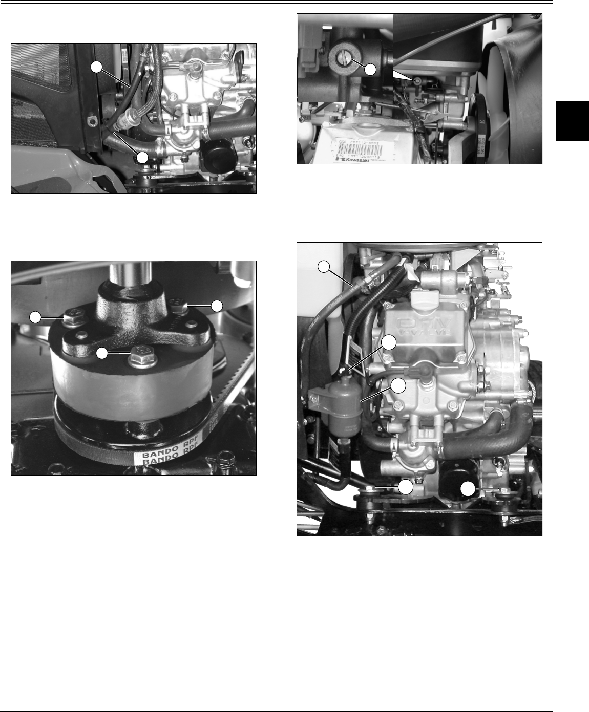
Engine - Gas (Liquid-Cooled) Repair - 75
ENGINE - GAS (LIQUID-COOLED) REPAIR
18.Loosen throttle cable clamp (T) and disconnect cable
(U).
MX15403
Picture Note: Carburated engine fuel lines.
19.Disconnect and plug the fuel supply line (V) and fuel
return line (W) on carburated engine.
MX13614
20.Remove the three cap screws (X) at the rear of the drive
coupler and disconnect drive shaft from engine sheave.
Note: Fuel lines may be pressurized on the fuel
injected engine. Relieve pressure prior to servicing
fuel lines or components.
MX15401, MX14502
Picture Note: Fuel pressure relief screw, fuel
injected engine.
21.Release fuel pressure by loosening pressure relief
screw (Y), then tighten screw.
MX16001
Picture Note: Fuel injected engine, right side.
22.Disconnect and plug the fuel return line (Z), and
disconnect the supply line quick-coupler (AA) at the top of
the fuel filter (AB), on the fuel injected engine.
23.Remove the two right side engine mount bolts (AC),
washers and nuts, and the left rear motor mount bolt,
washer and nut.
24.Detach any hydraulic lines that may be supported by J-
clips or other hardware connected to the bottom of the
engine.
V
W
X
X
X
Y
Z
AB
AC AC
AA

Engine - Gas (Liquid-Cooled) Repair - 76
ENGINE - GAS (LIQUID-COOLED) REPAIR
Note: If no spreader bar is available, remove air cleaner
assembly and cover fuel injection air intake hole with a
clean shop rag to prevent entry of foreign objects.
MX16004
25.Connect engine hoist to lift hooks on engine using
spreader bar (AD) with lift chains to avoid damage to air
cleaner during removal.
26.Lift engine slightly and pull away from radiator to clear
shroud and fuel filter, then remove engine from machine.
Installing:
1. Lower the engine so that it rests slightly on the engine
mounts.
2. Align the engine and mounts, then install the two right
side and the left rear engine mount bolts, washers and nuts
finger tight.
3. Lower engine fully, disconnect hoist from engine lifting
brackets and remove hoist.
4. Route ground wire bundle from main wiring harness to
original position by left front engine mount.
5. Install engine ground strap and ground wire bundle from
main wiring harness with left front engine mount hardware,
tighten hardware finger tight.
6. Tighten all engine mount bolts to 50 N•m (37 lb-ft).
7. Align drive coupler with engine sheave, install drive
coupler mounting bolts and tighten to 40 N•m (30 lb-ft).
8. Unplug and connect fuel return hose and connect fuel
supply hose quick-coupler to fuel filter.
9. Secure any hydraulic hoses, if removed in an earlier
step, to appropriate hardware attached to the bottom of the
engine.
10.Secure wire harness J-clip and ground wire to back of
left cylinder head with retaining bolt and tighten.
11.Connect main wire harness plug-in connectors and
bullet connector to the corresponding engine connectors.
12.Connect the main wiring harness power lead bundle
and positive battery cable to the starter terminal, and
connect the solenoid plug.
13.Connect and adjust throttle cable. See “Throttle Cable
Adjustment” on page 40.
14.Install throttle cable shield.
15.Remove the right side lift bracket and four flange nuts
from the muffler flange studs.
16.Install new muffler gaskets.
17.Install the muffler and the right side lifting bracket in their
original locations and tighten mounting hardware. See
“Muffler Removal and Installation” on page 58.
18.Install battery shield and attach positive battery cable
retainer clip.
19. Install battery and connect positive battery cable.
20.Install and tighten upper and lower radiator hoses.
21.Replace radiator coolant.
22.Install hood and connect headlight plug.
23.Connect negative battery cable.
AD

Engine - Gas (Liquid-Cooled) Repair - 77
ENGINE - GAS (LIQUID-COOLED) REPAIR
Flywheel Removal and Installation
Procedure:
1. Park machine safely. See Parking Machine Safely in
Safety section.
2. Remove engine from machine. See “Engine Removal
and Installation” on page 73.
3. Remove plastic cover surrounding lower half of flywheel,
and outer sheave attached to flywheel.
MX16077
4. Hold flywheel with strap and remove flywheel bolt (A).
5. Thread a flywheel puller into the pulling holes (B) and
remove the flywheel.
6. To remove stator coil, see “Stator Replacement” on
page 230 in the Electrical section.
7. To remove ignition coil, see “Ignition Coil Replacement
and Adjustment” on page 230 in the Electrical section.
8. Align the flywheel keyway with the key on the crankshaft
and install flywheel.
MX16079
9. Install spring washer (C) as shown.
10.Install and tighten the flywheel bolt.
11.Install engine into machine.
Specification:
Flywheel Bolt . . . . . . . . . . . . . . . . . . . . . 56 N•m (41 lb-ft)
Push Rod/Rocker Arm Removal and
Installation
Removing:
1. Set the piston on the cylinder you are working on at top
dead center (TDC) of the power stroke.
2. Remove rocker covers. See “Cylinder Head Removal
and Installation” on page 65.
MX11613
3. Remove the valve clearance adjusting nuts (A),
washers, and bolts (C).
4. Remove the rocker arms (E), along with collars (D), to
provide access to the push rods (B). Pull out the push rods
and mark each rod so it can be installed in the original
position during reassembly.
MX16115
5. Remove two bolts (F) and rocker arm bracket (G).
A
B
C
C
D
A
B
A
E
BC
D
F
F
G

Engine - Gas (Liquid-Cooled) Repair - 78
ENGINE - GAS (LIQUID-COOLED) REPAIR
Inspection:
MX16116
• Clean the rocker arms and inspect the push rod and
valve stem contact points (I). If the contact surfaces are
excessively worn or show signs of galling or surface flaking,
replace the rocker arm.
• Measure the inside diameter of the rocker arm bearing
(B) at several points using a dial bore gauge or inside
micrometer. If the inside diameter is more than the service
limit, replace the rocker arm.
Rocker Arm Bearing Inside Diameter:
Service Limit . . . . . . . . . . . . . . . . . . 11.05 mm (0.435 in.)
MX11799
• Inspect the push rods for damage or excessive runout.
Place each push rod in V blocks set as near to the ends of
the rod as possible. Set up a dial gauge at the center point
of the push rod. Turn the rod to measure the runout. Check
the difference between the highest and lowest dial readings
to determine runout. If this figure exceeds 0.5 mm (0.02
in.) the push rod must be replaced.
MX16117
• Measure the inside diameter (J) of the rocker arm collar
(D) with a micrometer at several points of the bearing of the
rocker arm. If the outside diameter is less than the service
limit, replace the rocker arm collar.
Rocker Arm Collar Outside Diameter:
Service Limit. . . . . . . . . . . . . . . . . . . 10.91 mm (0.43 in.)
Installing:
1. Set the piston at TDC on the cylinder you are working on
before beginning push rod installation.
MX16115
2. If removed, install bracket (G) and two bolts (F). Tighten
bolts to 22 N•m (16 lb-ft).
I
H
J
D
F
F
G

Engine - Gas (Liquid-Cooled) Repair - 79
ENGINE - GAS (LIQUID-COOLED) REPAIR
MX11802
3. Install each push rod (K) in its original position by
inserting the end of the rod so it is sliding along the inside
wall of the crankcase (L). Position the push rod on the
tappet (M).
4. Check that both intake and exhaust push rods on the
cylinder you are assembling are at the lowest position on
the cam lobes (N). If not, turn the flywheel clockwise one
turn (360o) and reset the piston at TDC of the power stroke.
MX16117
5. Insert the collar (D) into the rocker arm hole so that the
groove (P) of the collar faces upward, then set them on the
bracket (O), positioning the push rod ends onto the rocker
arm detents.
6. Insert the washer (Q) onto the bolt (C), and insert the
bolt into the hole at the right side of the bracket and through
the collar installed with the rocker arm.
7. Install the nut (A) onto the bolt and tighten the nut
temporarily.
8. Apply clean engine oil to the rocker arm pivot seat area
and the contact points on the arm when reinstalling the
rocker arms. Perform a valve clearance adjustment as
detailed in the Engine Tests and Adjustments section of this
manual.
9. Install rocker covers.
Valve Train Removal and Installation
Procedure:
1. Remove cylinder head. See “Cylinder Head Removal
and Installation” on page 65.
Note: When removing valve train, mark all parts so
they can be reinstalled in their original position.
MX11613
2. Remove valve clearance adjusting nuts (A), bolts (B)
and associated hardware to remove rocker arms (D).
3. Remove rocker arm bracket (C).
MX16119
K
L
M
N
G
E
A
C
D
Q
O
P
B
A
A
D
B
C
G
E
F
H

Engine - Gas (Liquid-Cooled) Repair - 80
ENGINE - GAS (LIQUID-COOLED) REPAIR
4. Support the valve heads inside the combustion chamber
with a suitable block such as a piece of wood.
5. Remove the spring retainer (E) by pushing down with
your thumbs and removing the collets (G).
6. Remove the spring (H) and valve (F).
Note: Bottom spring retainer (J) can only be removed
with stem seal.
MX16120
7. Remove the stem seals (I). Stem seal replacement is
not mandatory on a low hour engine, but is recommended,
particularly if a new valve has been installed.
Note: Valve guides (K) are not replaceable. If a valve
guide is damaged or worn beyond maximum
specifications, the head casting must be replaced.
8. Check to see if the valve seats properly in the valve
seat. If not, resurface the valve seat and/or replace the
valve.
9. Install new stem seals if necessary.
10.Apply engine oil to the valve stem to avoid damaging the
valve stem seal. Install the valve and check for smooth
operation in the valve guide. Replace valve if valve binds in
guide, or guide to stem clearance is excessive.
11.Install valve spring, collets and spring retainer on the
valve.
12.Install rocker arm bracket (C).
13.Apply clean engine oil to the rocker arm at the spherical
pivot seat, and the points where the arm contacts the push
rod and the valve stem end.
14.Install the rocker arm (and associated hardware) on the
rocker arm bracket, and tighten the bolt and nut temporarily.
Perform a valve adjustment as detailed in Valve Clearance
Inspection and Adjustment in the Engine Tests and
Adjustments section.
Crankcase Cover Removal and Installation
Procedure:
1. Remove engine from machine. See “Engine Removal
and Installation” on page 73.
2. Drain engine oil.
MX16110
3. Remove governor control panel (B) and governor arm
(A). See “Governor Assembly Removal and Installation” on
page 82.
4. Remove rocker covers. See “Cylinder Head Removal
and Installation” on page 65.
MX16129
5. Remove the ten (10) cover mounting bolts and remove
the crankcase cover (C) from the crankcase. There are two
knock points (D) on the cover where a plastic or wood
mallet can be used to gently tap the cover loose.
6. Remove the crankcase cover gasket and any gasket
residue from both the cover and the crankcase mating
area.
I
K
J
A
B
5
4
2
6
10
9
D
7
8
1
D
3
C

Engine - Gas (Liquid-Cooled) Repair - 81
ENGINE - GAS (LIQUID-COOLED) REPAIR
7. Clean the mating surfaces of the cover and the
crankcase using a high flash point solvent. Blow out the oil
passage in the cover using compressed air.
8. Replace the crankshaft PTO oil seal if necessary. Note
the following while replacing this seal:
MX11847
• The crankshaft PTO oil seal is installed with the
marks (E) facing out. Press the new seal into the cover
until it is flush with the flange surface (F). Pack high
temperature grease (H) into the space between the seal
lip (G) and the dust lip (I).
MX16130
9. Check to see that the O-Rings (L) are in place on the
crankcase as shown above.
10.Apply silicone sealant bead (J), 1 - 2 mm (0.04 - 0.08
in.) wide, to mating surface (K) of the crankcase (in areas
shown above).
11.Check that the crankshaft dowels (N) are in place on the
crankcase and install a new gasket on the crankcase.
MX16129
12. Install the crankcase cover (C). Noting the different
length of bolts, tighten the bolts 1/2 turn at a time in the
sequence shown, and to a final torque of 22 N•m (16.0 lb-
ft) when all bolts are tight.
13.Install rocker covers. See “Cylinder Head Removal and
Installation” on page 65.
14.Remove governor control panel and governor arm. See
“Governor Assembly Removal and Installation” on page 82.
15.Fill engine with approximately 1.8 L (1.9 qt) of oil.
16.Install engine onto machine. See “Engine Removal and
Installation” on page 73.
c Caution: Avoid Injury! Clean the crankcase and
cover in a well ventilated area where no sparks
or flames are present including appliance pilot
lights. Never use gasoline or a low flash-point
solvent to clean parts. A fire or explosion could
result.
H
E
F
G
I
K
J
J
J
N
N
ML
c Caution: Avoid Injury! Do not get the sealant
into the oil line hole (M) on the crankcase or
crankcase cover.
Important: Avoid Damage! If one cover bolt at a time
is tightened completely, the cover could be warped.
6
7
9
5
1
2
4
3
10
8
C

Engine - Gas (Liquid-Cooled) Repair - 82
ENGINE - GAS (LIQUID-COOLED) REPAIR
Crankcase Cover Inspection
Procedure:
MX16135
1. Drain engine oil and remove the crankcase cover. See
“Crankcase Cover Removal and Installation” on page 80.
2. Measure the inside diameter (A) of the PTO shaft
bearing at several points. This bearing is not replaceable. If
it is damaged, or the inside diameter is more than 42.09
mm (1.66 in.) the crankcase cover must be replaced.
3. Install crankcase cover. See “Crankcase Cover Removal
and Installation” on page 80.
4. Replace engine oil.
Governor Assembly Removal and Installation
Governor Arm Removal and Installation:
MX16110
Picture Note: FD671D engine shown; FD750D
engine does not have choke assembly.
1. To remove the governor arm, remove governor control
panel (C).
2. Loosen the clamp nut (D) and take off the governor arm
(A).
3. Clear the throttle link rod (B) from the governor arm and
choke lever.
4. Disassemble remaining parts, and visually inspect for
wear or damage; replace, as necessary.
MX14226
Picture Note: FD671D engine shown; FD750D
engine does not have choke assembly parts (L).
5. Insert the bracket (G) onto the governor shaft (H) to the
bottom of the woodruff are of the shaft, and tighten the
clamp nut (D) to 8 N•m (69 lb-in.).
6. Install the control panel assembly, and connect the
bracket with the governor spring (M).
7. Install the end of throttle link rod (B) with the link spring
(J) around it into the governor arm hole (I) and the other
end into the carburetor throttle lever (K) hole.
8. Install the governor arm (A) on the bracket (G) with the
bolt (F) and washer by turning the bolt counterclockwise so
the projection of the bracket fits into the governor arm hole
(E).
9. Loosen the bolt (F), and fully turn the bracket (G)
counterclockwise and hold it there.
10.Turn the top end of the governor arm (A)
counterclockwise to fully open the carburetor throttle valve
and tighten the bolt (F).
A
A
C
D
B
K
J
A
M
L
B
I
E
F
GH
D

Engine - Gas (Liquid-Cooled) Repair - 83
ENGINE - GAS (LIQUID-COOLED) REPAIR
Governor Removal and Installation:
1. Remove crankcase cover. See “Crankcase Cover
Removal and Installation” on page 80.
Note: To avoid damage to the surface of crankcase
cover, use suitable soft mats (C) as shown below.
MX16191
2. Remove the governor assembly (A) with the sleeve (B)
by prying the gear with two proper size screw drivers.
3. Remove the thrust washer.
MX16192
4. Install thrust washer (C).
5. Fit the sleeve (B) into the governor assembly (A), and
install them as a set.
Note: The sleeve (B) and the governor assembly (A)
cannot be installed separately. Push the set onto the
shaft (E) until inner flange (F) snaps into the groove (D)
securely.
6. Spin the governor assembly by hand and check that the
flyweights operate freely and the center sleeve moves
outward.
Governor Shaft Removal and Installation:
1. Remove camshaft. See “Camshaft/Tappet Removal and
Installation” on page 90.
2. Unscrew the governor arm clamp nut, and remove the
governor arm. See “Governor Arm Removal and
Installation:” on page 82.
MX16193
3. Remove the circlip (B) on the governor shaft (C), and
remove the governor shaft and washer (A).
Note: Replace the oil seal only if the lip shows signs of
leakage or it has been damaged. If the oil seal is
removed, install it after the shaft (C) is installed.
MX16194
4. The oil seal (E) must be assembled with the seal lip
towards inside of the engine.
5. Press in the oil seal approximately 1.0 mm (0.04 in.) (D)
flush or below the crankcase surface (F).
c Caution: Avoid Injury! Do not remove the
governor assembly unless it is necessary.
Once it has been removed, it must be replaced.
A
B
C
B
A
F
C
DE
A
B
C
E
D
F
A

Engine - Gas (Liquid-Cooled) Repair - 84
ENGINE - GAS (LIQUID-COOLED) REPAIR
MX16193
6. Apply engine oil to the governor shaft (C).
7. Insert the governor shaft into the crankcase and washer
(A).
8. Fit the circlip (B) securely into the groove of the
governor shaft (C), as shown above.
9. Check that the governor shaft moves freely in its
operating range.
Piston Removal and Installation
Removing:
1. Remove cylinder heads. See “Cylinder Head Removal
and Installation” on page 65.
2. Remove the crankcase cover and the camshaft. See
“Camshaft/Tappet Removal and Installation” on page 90.
MX16122
3. Turn the crankshaft to expose the connecting rod cap
bolts (A). Remove the bolts and take off the connecting rod
caps (B).
MX16123
4. Push the connecting rod end up into the cylinder, and
pull the piston and connecting rod assembly out the top of
the cylinder.
MX11819
MX16124
A
B
C
A
A
B
Important: Avoid Damage! Note location of the arrow
mark (F) on the piston head in relation to the “Made
in Japan” mark on the connecting rod. The “Made in
Japan” mark (D) on the No. 1 cylinder (C) connecting
rod must be face to face with the “Made in Japan”
mark (E) on the No. 2 cylinder (G) connecting rod.
Keep components together as a matched set.
F
CG
DE
F
E
H
I

Engine - Gas (Liquid-Cooled) Repair - 85
ENGINE - GAS (LIQUID-COOLED) REPAIR
5. Remove one of the piston snap rings (I) with a needle
nose pliers (H).
6. Push the piston pin out the side where the snap ring
was removed and remove the piston from the rod.
7. Remove the top and second rings with piston ring pliers.
MX11820
8. If piston ring pliers are not available, carefully spread the
ring opening with your thumbs and push up on the back
side of the ring (J) to remove it.
9. Remove the 3-piece oil ring using the thumb method.
Installing:
1. Inspect and clean the piston and rings before
installation. See “Inspect Piston and Cylinder” on page 87.
MX11821
2. Install a new oil control ring on the piston in the following
sequence:
• Install the expander (K) in the oil ring groove with the
ends (L) touching together, not overlapping.
• Install the upper and lower steel rails. Rails are
interchangeable and do not have an up or down
orientation.
MX11822
3. Install the scraper ring (N) in the second groove with the
notch facing down.
4. Install the compression ring (M) in the first groove with
the bevel facing down.
MX11823
5. Orient the ring gaps on the piston as shown:
• O - piston arrow mark
• P - top ring and upper steel rail end gaps
•Q - 30
o - 45o
• R - second ring and lower steel rail end gaps
MX16123
6. Apply fresh engine oil to the piston pin and assemble
the piston for the #1 cylinder (C) with the arrow mark (F)
facing away from the “Made in Japan” mark (D) on the
J
K
L
M
N
R
P
O
P
O
Q
Q
R
F
CG
DE

Engine - Gas (Liquid-Cooled) Repair - 86
ENGINE - GAS (LIQUID-COOLED) REPAIR
connecting rod.
7. Apply fresh engine oil to the piston pin and assemble
the piston for the #2 cylinder (G) with the arrow mark (F)
facing the “Made in Japan” mark (E) on the connecting rod.
MX16125
8. Fit new piston pin snap rings to both pistons. Align the
snap ring gap (S) so it does not align with the piston pin
hole notch (T).
9. Apply fresh engine oil to the piston skirt and cylinder
bore.
MX16126
10..Use a piston ring compression tool (U) to compress the
piston rings.
MX16127
11..Insert the piston and rod assembly in the cylinder bore
with the arrow mark on the piston (W) facing the flywheel
(X). Lightly tap the top of the piston with a plastic mallet (V)
to insert the piston assembly in the bore.
MX11830
12.Apply engine oil to the inner surface (Y) of the
connecting rod big end (Z) and caps (AA).
13.Align the rods on the crankshaft, and install the big end
rod caps in their original position.
14.Apply a small amount of engine oil to the thread (AB)
and seating surface of the rod cap bolts. Install bolts (AC)
and tighten to 21 N•m (186 lb-in.).
15.Install the camshaft and the crankcase cover. See
“Camshaft/Tappet Removal and Installation” on page 90.
Important: Avoid Damage! Do Not reuse piston pin
snap rings. Weakened and deformed snap rings
could fall out causing engine damage. Use only new
snap rings when reinstalling pistons.
S
T
U
V
U
Important: Avoid Damage! The connecting rod and
rod big end cap are machined as a matched set.
They must be replaced as a set in their original
position on the crankshaft.
X
W
AA
AC
AC
AB
AA
Y
Z
Z
Y

Engine - Gas (Liquid-Cooled) Repair - 87
ENGINE - GAS (LIQUID-COOLED) REPAIR
16.Install cylinder heads. See “Cylinder Head Removal and
Installation” on page 65.
Inspect Piston and Cylinder
Procedure:
MX11831
1. Remove the piston and piston rings. See “Piston
Removal and Installation” on page 84.
2. Scrape carbon deposits off the piston head (A) using an
appropriate scraper that will not gouge or scratch the
piston.
MX11832
3. Clean the piston ring grooves (B) with a broken ring or a
suitable tool.
MX11833
4. Check piston ring grooves for wear by inserting a new
ring in the piston and measuring the clearance between
piston and ring with a feeler gauge (C). Wear should not
exceed:
• Top and Second Ring - 0.15 mm (0.006 in.)
If piston ring groove clearance is greater than specified,
replace the piston.
Note: The three piece oil ring is difficult to measure for
ring groove clearance. Check both ring and piston
groove visually for damage or wear and replace either
component as necessary.
MX11834
5. Worn rings normally show visual evidence of wear such
as surface scratches or an extremely shiny sealing surface.
If you are considering reusing rings measure the following:
• Ring Thickness - Use a micrometer to measure at
several points around the ring (D). The minimum service
limit for both the top and second ring is 1.40 mm (0.055
in.). If any measurement is less than the service limit,
replace the entire set of rings.
Important: Avoid Damage! Never attempt to clean
carbon deposits with the piston in the engine.
Carbon particles will fall between the piston and
cylinder and could damage crankshaft bearings and
seals.
c Caution: Avoid Injury! The top and bottom
edges of the ring may be extremely sharp.
A
B
C
D

Engine - Gas (Liquid-Cooled) Repair - 88
ENGINE - GAS (LIQUID-COOLED) REPAIR
MX16128
• Piston Ring End Gap - Use the piston to push each
piston ring (E) into the cylinder bore to a point close to
the bottom of the cylinder bore. Measure the gap (F)
between the ends of the ring with a feeler gauge.
Top and Second Ring End Gap - 1.00 mm (0.04 in.)
service limit
Oil Ring End Gap - 1.2 mm (0.05 in.) service limit
If any measurement is greater than the service limit,
replace the entire set of rings.
MX16149
6. Inspect the crankcase for an accumulation of dust,
scale, and lime in the water jacket (G). If this accumulation
is observed, flush the cooling system.
Note: A cracked or porous casting is not visible to the
eye. If evidence of leakage of coolant from any
suspected area is found, replace the crankcase.
• Inspect the crankcase for coolant leakage outside the
water jacket. Small leaks may appear only as rust,
corrosion or stains, due to evaporation. If this is
observed, tighten bolts and/or replace the cylinder head
gasket.
• Inspect the crankcase for coolant leakage into the
engine. Leakage occurs through a loose cylinder head,
cracked or porous casting, and through the push rod
compartment (H). If coolant leakage appears in the
push rod compartment, replace the crankcase.
• Check the cylinder head gasket. If coolant is leaking
through gasket surfaces, check the gasket surfaces (I)
for traces of the leakage, and check to make sure the
cylinder head and block surfaces are smooth, clean and
level.
MX11838
7. Measure the outside diameter of the piston pin with a
micrometer at several points (J). If the outside diameter is
less than 18.96 mm (0.747 in.) the piston pin must be
replaced.
MX11839
8. Measure the inside diameter of the piston pin with a dial
bore gauge at several points (K) on both sides of the piston.
If the inside diameter is greater than 19.08 mm (0.751 in.)
the piston must be replaced.
MX11840
E
F
G
I
H
J
K
L

Engine - Gas (Liquid-Cooled) Repair - 89
ENGINE - GAS (LIQUID-COOLED) REPAIR
9. Measure the inside diameter of the connecting rod small
end with a dial bore gauge (L) at several points. If the inside
diameter is greater than 19.06 mm (0.75 in.) the piston
must be replaced.
MX11841
10.Measure the outside diameter of the piston (M) at a
point (N), 11 mm (0.43 in.) up from the bottom of the piston
and 90 degrees from the piston pin hole. If the outside
diameter is less than 77.7 mm (3.06 in.), the piston must
be replaced.
M86883
11.Clean the cylinder and inspect the bores for scoring,
signs of seizure or ridges at the top or bottom of the
cylinder.
12.Measure the cylinder inside diameter (O) using a dial
bore gauge. Measure the cylinder front to back and side to
side at the following points:
• 10 mm (0.394 in.) from top of cylinder
• 10 mm (0.394 in.) from bottom of cylinder
• 55 mm (2.165 in.) from top of cylinder
13.If any of the cylinder bore measurements are greater
than the following service limits, the cylinder must be bored
and honed (see Resizing Cylinder Bore and Cylinder Bore
Honing). If cylinder bores are within specifications and
show no signs of damage, new piston rings may be fitted
provided the cylinder bores are honed. This will restore the
proper cross hatch angle in the cylinder bores ensuring
proper lubrication and piston ring rotation.
• Standard Cylinder Bore Inside Diameter: 78.00 mm
(3.071 in.)
• Standard Cylinder Bore Service Limit: 78.08 mm
(3.074 in.)
• Standard Cylinder Bore Out-of-Round Service Limit:
0.056 mm (0.022 in.)
Cylinder Bore Honing
Procedure:
Note: To produce the proper cross hatch finish use a
drill speed of approximately 200 rpm and 40 - 60
strokes per minute. Lubricate hone liberally to prevent
build up on finishing stones.
M86885
1. The cylinder finish, (Cross Hatch) should be applied
when reconditioning a cylinder bore. The finishing stones
will produce the correct cross hatch necessary for proper
lubrication and piston ring rotation. The correct hatch angle
is approximately 45° (A).
2. It is recommended that the cylinder bores be
reconditioned to restore the cross hatch when new piston
rings are to be installed in a cylinder that is within
specification. Be careful not to hone oversize.
M
N
O
A

Engine - Gas (Liquid-Cooled) Repair - 90
ENGINE - GAS (LIQUID-COOLED) REPAIR
3. When cylinder and crankcase have been thoroughly
cleaned, use a white rag or napkin and wipe the cylinder
bore. If honing grit is present, it will appear as a grey
residue on rag. If any honing grit is evident, re-wash and
rinse entire cylinder and crankcase and check again. When
cleaning is complete, oil cylinder bore to prevent rusting.
Camshaft/Tappet Removal and Installation
Procedure:
1. Remove engine and drain oil. See “Engine Removal and
Installation” on page 73.
2. Remove crankcase cover. See “Crankcase Cover
Removal and Installation” on page 80.
3. Remove rocker covers. See “Cylinder Head Removal
and Installation” on page 65.
4. Place the piston at Top Dead Center (TDC) for the
cylinder you are working on.
MX16113
5. Remove rocker arms (B) and push rods (A). See “Push
Rod/Rocker Arm Removal and Installation” on page 77.
6. Turn the crankcase up side down so that tappets fall
away from cam lobes. Pull the camshaft out of the
crankcase.
MX16139
7. Remove the tappets (C) and mark them for
reinstallation.
8. Before reinstalling tappets and camshaft apply fresh
engine oil to:
• Tappet Journals
• Camshaft Journals
• Cam Lobe Surface
• Camshaft Gear
9. With the crankcases turned upside down, install the
tappets in their original positions.
MX16141
10.Slide the camshaft into position in the crankcase,
aligning the punch marks on the crankshaft gear (D) and
camshaft gear (E).
11.Install crankcase cover with a new gasket.
12.Install pushrods and check valve clearances before
reinstalling rocker covers. See “Valve Clearance
Adjustment” on page 43.
13.Install remaining components in the order they were
removed. Fill engine with new oil.
Important: Avoid Damage! Ensure that the entire
cylinder and crankcase are thoroughly cleaned after
honing. First wash the cylinder and crankcase
carefully in a solvent such as kerosene or
commercial solvent. Then thoroughly wash cylinder
and crankcase using a stiff brush with soap and hot
water. Rinse thoroughly with hot running water.
Repeat washing and rinsing until all traces of honing
grit are gone. Honing grit is highly abrasive and will
cause rapid wear to all of the internal components of
the engine unless it is completely removed.
B
A
C
D
E

Engine - Gas (Liquid-Cooled) Repair - 91
ENGINE - GAS (LIQUID-COOLED) REPAIR
Camshaft Disassembly and Inspection
Procedure:
MX16142
1. Inspect camshaft gear (A) for pitting, fatigue cracks,
burrs or uneven wear due to improper tooth contact.
Replace camshaft if necessary.
2. Check the top of the cam lobes (B) for signs of uneven
wear, grooving, pitting or flaking of hardened wear area.
Replace camshaft if any of these conditions exist.
MX16143
3. Remove the spring (C) from the ACR (Automatic
Compression Release) assembly. DO NOT attempt to
remove the ACR weight. If the ACR weight (D) is damaged,
or does not swing freely when shaking the cam, the
camshaft must be replaced.
4. Measure the height of each cam lobe (B), if less than
service limit replace camshaft.
MX16144
5. Measure both camshaft journals (E) at several points
around the journal circumference. If any journal is worn
less than the service limit, replace the camshaft.
MX16145
6. Measure inside diameter (F) of the camshaft bearing
bore in crankcase at several points. This bearing is not
serviceable, so it will be necessary to replace the
crankcase if the inside diameter is greater than the service
limit.
MX16146
7. Measure inside diameter (G) of the camshaft bearing
bore in crankcase cover at several points. This bearing is
Important: Avoid Damage! Damaged or worn cam
lobes usually indicate damaged tappets. Check
tappets when replacing camshaft.
A
B
C
D
B
E
E
F
G

Engine - Gas (Liquid-Cooled) Repair - 92
ENGINE - GAS (LIQUID-COOLED) REPAIR
not serviceable, so it will be necessary to replace the
crankcase cover if the inside diameter is greater than the
service limit.
8. Install a new spring on the ACR assembly.
9. Install the camshaft in the crankcase. See “Camshaft/
Tappet Removal and Installation” on page 90.
Cam Lobe Height:
Service Limit Intake . . . . . . . . . IN 33.594 mm (1.323 in.)
Service Limit Exhaust . . . . . . EX 33.594 mm (1.323 in.)
Camshaft Journal Diameters:
PTO Side . . . . . . . . . . . . . . . . . . . . 19.927 mm (0.785 in.)
Flywheel Side . . . . . . . . . . . . . . . . 19.927 mm (0.785 in.)
Camshaft Bearing Bores:
Crankcase Camshaft Bore. . . . . . 20.081 mm (0.791 in.)
Crankshaft Cover Camshaft Bore 20.081 mm (0.791 in.)
Crankshaft Removal and Replacement
Procedure:
1. Remove engine and drain oil. See “Engine Removal and
Installation” on page 73.
2. Remove flywheel. See “Flywheel Removal and
Installation” on page 77.
3. Remove camshaft and tappets. See “Camshaft/Tappet
Removal and Installation” on page 90.
4. Remove connecting rod and piston assemblies. See
“Piston Removal and Installation” on page 84.
MX16147
5. Pull the crankshaft (A) out of the crankcase. It may be
necessary to tap on the crankshaft with a wood or plastic
mallet to loosen the crankshaft.
6. Before installing the crankshaft, clean the crankshaft
journals and the crankcase bearing surfaces thoroughly.
7. Pack high temperature grease into the crankcase oil
seal.
8. Apply engine oil to the crank journals and bearing
surfaces and carefully insert crank (A) into the main
bearing and oil seal in the crankcase.
9. Install pistons and rods on crankshaft (see Piston
Removal/Replacement).
10.Install camshaft and tappets. See “Camshaft/Tappet
Removal and Installation” on page 90.
11.Install a new crank oil seal if necessary in the crankcase
cover. Install the crankcase cover. See “Crankcase Cover
Removal and Installation” on page 80.
Crankshaft Inspection
Procedure:
1. Remove crankshaft. See “Crankshaft Removal and
Replacement” on page 92.
2. Clean the crankshaft and connecting rods with a high
flash point solvent and dry with compressed air.
3. Inspect the teeth of the crankshaft gear for fatigue
cracks, pitting or signs of uneven tooth contact. Replace
crank gear if necessary.
4. Inspect the crankshaft and connecting rod bearing
surfaces for excessive wear, uneven contact or gouging
and scratching. Components should be replaced if any of
these conditions exist.
MX16148
5. Measure the crankpin outside diameter (A) at several
points around the circumference. If the crankpin diameter is
less than the service limit at any point, replace the
crankshaft.
c Caution: Avoid Injury! Used tappets are mated
to their camshaft lobes. Mark them for
installation in the same bore they were
removed from.
A
A

Engine - Gas (Liquid-Cooled) Repair - 93
ENGINE - GAS (LIQUID-COOLED) REPAIR
MX16148
6. Measure the crankpin width (C) at several points with a
dial caliper. If crankpin width exceeds the service limit at
any point, replace the crankshaft.
7. Measure the flywheel side (B) and PTO side (D) main
journals at several points. If either journal is less than the
service limit, the crankshaft must be replaced.
MX11892
8. Measure the crankshaft runout. Set the crankshaft in a
flywheel alignment jig or on V blocks. Set up dial gauges
(E) at both bearing journals. Turn the crankshaft slowly by
hand and measure the runout. The difference between the
highest and lowest dial gauge reading is the amount of
runout. If the measurement at either journal exceeds the
service limit, the crankshaft must be replaced.
MX16150
9. Measure the inside diameter (F) of the crankshaft
journal bearing on the crankcase at several points. Replace
the journal bearing if the inside diameter is more than the
service limit.
MX16151
10.The journal bearing (G) is press fit into the crankcase
(I).
• Remove the oil seal on the crankcase. (Note: The oil
seal should be replaced once removed.)
• Place the crankcase on a support block (J), with the
oil seal side up.
• Using a bushing tool (H), drive out the bearing as
shown.
Specifications:
Crankpin Outside Diameter (Service Limit)
. . . . . . . . . . . . . . . . . . . . . . . . . . . . 39.950 mm (1.573 in.)
Crankpin Width (Service Limit). . . . 46.50 mm (1.83 in.)
Crank Main Journal PTO Side (Service Limit)
. . . . . . . . . . . . . . . . . . . . . . . . . . . . 41.935 mm (1.651 in.)
Crank Main Journal Flywheel Side (Service Limit)
. . . . . . . . . . . . . . . . . . . . . . . . . . . . 41.935 mm (1.651 in.)
Crank shaft Runout (Service Limit) 0.05 mm (0.002 in.)
Crankcase Journal Bearing Inside Diameter
(Service Limit) . . . . . . . . . . . . . . . . 42.14 mm (1.659 in.)
C
B
D
E
F
H
I
G
J

Engine - Gas (Liquid-Cooled) Repair - 94
ENGINE - GAS (LIQUID-COOLED) REPAIR
Connecting Rod Inspection
Procedure:
1. Remove pistons and connecting rods. See “Piston
Removal and Installation” on page 84.
MX16152
2. Measure the connecting rod big end width (A) with a
micrometer or dial caliper. If the measurement is less than
the service limit, the rod must be replaced.
3. Apply a light film of oil to the threads of the cap bolts.
Install the rod cap and the cap bolts and tighten the bolts to
21 N•m (180 lb-in.). Measure the inside diameter (B) of the
big end at several points with a telescoping gauge or inside
micrometer. If the inside diameter is greater than the
service limit, the rod and cap must be replaced.
MX11898
4. Measure connecting rod bend. Insert an arbor the same
size as the big end through the connecting rod big end.
Insert an arbor (D) 100 mm (3.397 in.) (E) or longer the
same diameter as the small end through the connecting rod
small end. Place V blocks on a surface plate, and support
the big end arbor in the V blocks.
5. Hold the small end of the rod straight up vertically and
measure from the surface plate to the small end arbor on
both sides of the connecting rod. Measurement must be
taken at a point that is exactly 100 mm (3.397 in.) apart.
The difference between the two measurements determines
the rod bend (C). If the connecting rod bend exceeds the
service limit the rod and rod cap must be replaced.
MX11901
6. Measure connecting rod twist. With the big end mounted
in V blocks, hold the connecting rod horizontally and
measure the amount that the small end arbor varies (F)
from being parallel with the surface plate over a 100 mm
length (G). If twist exceeds the service limit the rod and cap
must be replaced.
7. Install the connecting rods and pistons. See “Piston
Removal and Installation” on page 84.
Specifications:
Connecting Rod Big End Width Service Limit
. . . . . . . . . . . . . . . . . . . . . . . . . . . . . . 22.35 mm (0.88 in.)
Connecting Rod Big End Inside Diameter Service Limit
. . . . . . . . . . . . . . . . . . . . . . . . . . . . 40.055 mm (1.577 in.)
Connecting Rod Bend Service Limit
. . . . . . . . . . . . . . . . . . . . . . 0.15. mm (0.006 in.) over 100
mm (3.94 in.)
Connecting Rod Twist Service Limit
. . . . . . . . . . . . . . . . . . . . . . 0.15 mm (0.006 in.) over 100
mm (3.94 in.)
B
A
D
E
C
FG

Engine - Gas (Liquid-Cooled) Repair - 95
ENGINE - GAS (LIQUID-COOLED) REPAIR
Breather Valve Removal and Installation
Procedure:
1. Remove engine from machine. See “Engine Removal
and Installation” on page 73.
MX16153
2. Remove the four (4) bolts holding the breather cover (B)
to the crankcase.
3. Inspect gasket (A) for damage, and replace if necessary.
MX16154
4. Unscrew the mounting screw (C), and remove the back
plate (D) and reed valve (E).
• Inspect the reed valve (E) for breakage, hair cracks
or distortion. Replace valve if any signs of wear or
damage are present.
• Inspect the back plate (D) for damage or a rough
contact surface. Replace if necessary.
• Inspect the valve seating surface for nicks, burrs,
scratches or fretting. If damage or wear is evident,
remove the reed valve and backing plate and clean the
surface with fine emery paper.
Note: The mounting screw (C) is self-tapping. Be aware
that mis-threading or overtightening the screw will
strip the female threads and ruin the hole.
5. To install assembly, align the center of the valve seat
with the center of the reed valve (E) and back plate (D),
then tighten the mounting screw (C).
6. Before installing cover, be sure the drain hole (F) does
not accumulate any debris.
7. Install a new cover gasket (A) and install cover (B).
Tighten four breather valve cover mounting bolts to 20 N•m
(180 lb-in.).
Oil Pump Removal and Installation
Procedure:
1. Remove crankcase cover. See “Crankcase Cover
Removal and Installation” on page 80.
MX16156
2. Remove two cap screws (B) holding oil screen filter (A)
onto crankcase cover.
MX16155
3. Remove the remaining three (3) bolts (C) holding the oil
pump assembly (D) to the crankcase cover and remove
pump assembly.
B
A
C
D
E
F
A
B
D
C

Engine - Gas (Liquid-Cooled) Repair - 96
ENGINE - GAS (LIQUID-COOLED) REPAIR
MX11912
4. Remove the relief valve ball (I) and spring (J) from the
crankcase cover.
5. The pump can be disassembled by removing the pin (M)
and separating the pump gear (E) from the pump shaft (H)
and the cover plate (K).
6. Remove the inner (G) and outer rotor (F) from the pump
cavity.
7. Assemble the pump in reverse order of disassembly.
8. Fill the rotor housing in the crankcase cover with fresh
oil for initial lubrication.
Note: When installing the pump parts assembly, align
the 6 mm diameter hole (L) on the cover plate with the
center of the relief valve.
MX16155
9. Install the relief valve and ball in the crankcase cover,
then install the pump parts assembly into the cover.
10.Install the pump assembly into the crankcase cavity
making certain to align the 6 mm diameter hole (L) in the
cover plate with center of the relief valve. Put the oil screen
filter in position, and install the five (5) mounting bolts
tightening to 6 N•m (52 lb-in.).
11.Install the crankcase cover with a new gasket. See
“Crankcase Cover Removal and Installation” on page 80.
Oil Pump Inspection
Procedure:
MX16157
1. Remove the oil pump assembly from the crankcase
cover. See “Oil Pump Removal and Installation” on
page 95. Visually inspect the pump gear, inner and outer
rotor and cover plate for wear or damage. Replace
components as necessary.
2. Install inner and outer rotor in crankcase cavity and
check clearance between inner and outer rotor with a feeler
gauge. Take this measurement at the point where the high
point of the inner rotor meets the high point of the outer
rotor (A). If the clearance exceeds the service limit replace
the inner and outer rotors as a set.
MX16158
3. Measure the thickness (B) of the outer rotor with a
micrometer at several points. If the thickness is less than
the service limit at any point, replace the inner and outer
rotors.
C
E
I
H
F
G
M
J
K
L
D
C
L
A
BC

Engine - Gas (Liquid-Cooled) Repair - 97
ENGINE - GAS (LIQUID-COOLED) REPAIR
4. Measure the outside diameter (C) of the outside rotor at
several points with a micrometer. If the rotor diameter is
less than the service limit, replace the inner and outer rotor
as a set.
MX16159
5. Measure the inside diameter (E) of the pump housing
with an inside micrometer at several points. If the inside
diameter of the cover is greater than the service limit the
crankcase cover must be replaced.
6. Measure the depth (D) of the pump housing with a depth
micrometer at several points. If any measurement is greater
than the service limit the crankcase cover must be
replaced.
7. Measure the inside diameter (F) of the pump shaft
bearing in the crankcase cover at several points with an
inside micrometer. If the inside diameter exceeds the
service limit at any point it will be necessary to replace the
crankcase cover.
MX16160
8. Measure the outside diameter (G) of the pump shaft
with a micrometer at several points. If the diameter is less
than the service limit, replace the pump shaft.
MX16161
9. Remove the relief valve spring and steel ball from the
crankcase cover. Clean the valve seat and valve
components with a high flash point solvent, and blow any
foreign particles out of the seat with compressed air.
Inspect the steel ball for wear or dimpling. Replace the
steel ball and spring if any wear or damage is evident.
10.Measure the free length (H) of the spring with a vernier
caliper. If the free length of the spring is less than the
service limit, replace the spring.
11.Install oil pump assembly in crankcase cover. See “Oil
Pump Removal and Installation” on page 95.
Specifications:
Inner to Outer Rotor Clearance (Service Limit) (A)
. . . . . . . . . . . . . . . . . . . . . . . . . . . . . . . 0.3 mm (0.012 in.)
Outer Rotor Outside Diameter (Service Limit) (C)
. . . . . . . . . . . . . . . . . . . . . . . . . . . . .40.47 mm (1.593 in.)
Outer Rotor Thickness (Service Limit) (B)
. . . . . . . . . . . . . . . . . . . . . . . . . . . . 19.830 mm (0.781 in.)
Pump Housing Inside Diameter (Service Limit) (E)
. . . . . . . . . . . . . . . . . . . . . . . . . . . . 40.801 mm (1.606 in.)
Pump Housing Depth (Service Limit) (D)
. . . . . . . . . . . . . . . . . . . . . . . . . . . . 20.230 mm (0.797 in.)
Pump Shaft Outside Diameter (Service Limit) (G)
. . . . . . . . . . . . . . . . . . . . . . . . . . . 10.923 mm (0.4300 in.)
Pump Shaft Bearing Inside Diameter (Service Limit) (F)
. . . . . . . . . . . . . . . . . . . . . . . . . . . . 11.072 mm (0.436 in.)
Spring Free Length (H) . . . . . . . . . . 19.50 mm (0.77 in.)
c Caution: Avoid Injury! Clean parts in a well
ventilated area using a high flash point solvent.
Make certain no spark or flame such as pilot
light is near the work area.
D
F
E
G
H

Engine - Gas (Liquid-Cooled) Repair - 98
ENGINE - GAS (LIQUID-COOLED) REPAIR
Oil Screen Removal and Installation
Procedure:
1. Remove the crankcase cover. See “Crankcase Cover
Removal and Installation” on page 80.
MX16156
2. Remove two cap screws (B) holding oil screen filter (A)
onto crankcase cover.
MX16163
3. Clean the oil screen (C) with a high flash-point solvent
and remove any particles stuck to it. Check the screen
carefully for any damage, or metal particles that might
indicate internal engine damage. If the screen is damaged,
replace entire oil screen filter (A).
4. Install the pipe on the oil pump assembly with the two
cap screws. Tighten the cap screws to 6 N•m (52 lb-in.).
5. Install crankcase cover. See “Crankcase Cover Removal
and Installation” on page 80.
c Caution: Avoid Injury! Clean parts in a well
ventilated area using a high flash point solvent.
Make certain no spark or flame such as pilot
light is near the work area.
A
B
C
A

Electrical Table of Contents - 99
ELECTRICAL TABLE OF CONTENTS
Electrical
Table of Contents
General Information......................................103
Reading Electrical Schematics...................103
Theory of Operation Information ................104
Diagnostic Information................................104
Wire Color Abbreviation Chart....................104
Common Circuit Tests................................105
Conductors For 12 Volt Circuits .................105
Specifications ...............................................107
General Specifications ...............................107
Test and Adjustment Specifications ...........107
Repair Specifications..................................108
Special or Essential Tools ..........................109
Other Materials...........................................110
Component Location....................................111
Right Side...................................................111
Left Side .....................................................112
Engine Components (FD671D) ..................113
Engine Components (FD750D EFI) ...........114
Instrument Panel ........................................115
Schematics and Harnesses .........................116
Schematic and Wiring Harness Legend -
X700 ...........................................................116
Schematic And Wiring Harness Legend -
X720/X724/X728 ........................................117
Electrical Schematic - X700 Carbureted
(1 of 2) ........................................................119
Electrical Schematic - X700 Carbureted
(2 of 2) ........................................................120
W1 Main Wiring Schematic - 720/X724/X728
EFI (1 of 2) .................................................121
W1 Main Wiring Schematic - 720/X724/X728
EFI (2 of 2) .................................................122
Liquid Cooled EFI Schematic (1 of 2).........123
Liquid Cooled EFI Schematic (2 of 2).........124
W1 Main Wiring Harness - X700 Carbureted
(1 of 2) ........................................................125
W1 Main Wiring Harness - X700 Carbureted
(2 of 2) ........................................................126
W1 Main Wiring Harness - X720/X724/X728
EFI (1 of 2) .................................................127
W1 Main Wiring Harness - X720/X724/X728
EFI (2 of 2) .................................................128
W2 Engine Wiring Harness - X700.............129
W2 Engine Wiring Harness - X720/X724/
X728 EFI.................................................... 130
W2 Engine Wiring Harness Circuit Schematic -
X720/X724/X728........................................ 131
W3 Headlight Wiring Harness.................... 132
W4 Rear Wiring Harness ........................... 132
W5 PTO Option Wiring Harness................ 132
W6 Auxiliary Alternator Wiring Harness..... 133
W6 Auxiliary Alternator Wiring Harness Circuit
Schematic .................................................. 134
A2 EFI Module Pin and Signal Location .... 135
W1 Main Wiring Harness Color Codes -
X700 .......................................................... 136
W1 Main Wiring Harness Color Codes -
X720/X724/X728 EFI................................. 137
W2 Engine Wiring Harness Color Codes -
X700 .......................................................... 138
W2 Engine Wiring Harness Color Codes -
X720/X724/X728........................................ 138
W3 Headlight Wiring Harness Color
Codes ........................................................ 138
W4 Rear Lights Wiring Harness Color
Codes ........................................................ 138
W5 PTO Option Wiring Harness Color
Codes ........................................................ 139
W6 Auxiliary Alternator Wiring Harness
Color Codes............................................... 139
Operation and Diagnostics ......................... 140
Power Circuit Operation - X700................. 140
Power Circuit Electrical Schematic - X700 141
Power Circuit Diagnosis - X700................. 143
Power Circuit Operation - X720/X724/
X728 .......................................................... 149
Power Circuit Electrical Schematic - X720/
X724/X728 EFI .......................................... 151
Power Circuit Diagnosis - X720/X724/
X728 EFI.................................................... 154
Cranking Circuit Operation - All Models..... 161
Cranking Circuit Electrical Schematic -
All Models .................................................. 162
Cranking Circuit Diagnosis - All Models..... 163
Charging Circuit Operation - All Models
(Standard Configuration) ........................... 164
Charging Circuit Operation - All Models
(With Auxiliary Alternator) .......................... 164
Charging Circuit Electrical Schematic -
All Models .................................................. 165

Electrical Table of Contents - 100
ELECTRICAL TABLE OF CONTENTS
Charging Circuit Diagnosis - All Models
(Standard Configuration) ............................167
Charging Circuit Diagnosis - All Models
(With Optional Alternator)...........................167
Ignition Circuit Operation - X700 ................168
Ignition Circuit Electrical Schematic - X700169
Ignition Circuit Diagnosis - X700 ................171
Ignition Circuit Operation - X720/X724/X728
EFI..............................................................173
Ignition Circuit Electrical Schematic - X720/
X724/X728 EFI ...........................................174
Ignition Circuit Diagnosis - X720/X724/
X728 EFI ....................................................176
PTO/RIP Circuit Operation - All Models .....177
PTO/RIP Circuit Electrical Schematic -
All Models...................................................179
PTO/RIP Circuit Diagnosis - All Models .....181
Display Panel Circuit Operation -
All Models...................................................185
A1 Display Panel Pin and Signal Location 187
Lights Circuit Operation - All Models ..........188
Lights Circuit Electrical Schematic -
All Models...................................................189
Lights Circuit Diagnosis - All Models ..........190
Power Port Circuit Operation - All Models..192
Power Port Circuit Electrical Schematic -
All Models...................................................192
Power Port Circuit Diagnosis - All Models..193
Fuel Pump and Fuel Shutoff Circuit Operation -
X700 ...........................................................194
Fuel Pump and Fuel Shutoff Circuit Electrical
Schematic - X700 .......................................195
Fuel Pump and Fuel Shutoff Circuit Diagnosis -
X700 ...........................................................196
Fuel Pump and Fuel Injector Circuit Operation
- X720/X724/X728 ......................................197
Fuel Pump and Fuel Injector Circuit Electrical
Schematic - X720/X724/X728 ....................198
Fuel Pump and Fuel Injector Circuit Diagnosis
- X720/X724/X728 ......................................200
Fuel Injection Sensor and Diagnostic Circuit
Operation - X720/X724/X728 .....................203
Fuel Injection Sensor and Diagnostic Circuit
Electrical Schematic - X720/X724/X728.....206
Tests and Adjustments ............................... 208
Common Circuit Tests ............................... 208
Ground Circuit Tests.................................. 208
Battery Voltage and Specific Gravity Test . 208
Battery - Charge ........................................ 209
Battery - Load Test .................................... 210
Regulated Amperage and Voltage Test..... 211
Regulated Voltage Test ............................. 211
Unregulated Voltage Test (Standard
Configuration) ............................................ 212
Unregulated Voltage Test (Optional Auxiliary
Alternator).................................................. 212
Stator Resistance Test (Standard
Configuration) ............................................ 213
Alternator Resistance Test (Optional Auxiliary
Alternator).................................................. 213
Starting Motor Condition ............................ 214
Starter Solenoid Test................................. 214
Starting Motor Amp Draw Test .................. 215
Starting Motor No-load Amperage and
RPM Test................................................... 215
Starting Motor Field Windings Test............ 216
Starter Armature Test ................................ 216
Engine Coolant Temperature Sensor Test 216
Engine Oil Pressure Switch Test ............... 217
Lights Switch Test...................................... 217
PTO/RIP Switch Test................................. 218
Relay Test.................................................. 218
Power Port Switch Test ............................. 219
Key Switch Test......................................... 219
Seat Switch Test........................................ 220
Brake Switch Test and Adjustment............ 220
RIO Switch Test......................................... 221
RIO Switch Adjustment.............................. 222
Fuse Test................................................... 222
PTO Solenoid Test (Standard Front PTO). 222
PTO Switch Test (Optional Rear PTO
Installed) .................................................... 223
Fuel Shutoff Solenoid Test - X700............. 224
Diode Test ................................................. 224
Fuel Tank Sensor Test .............................. 224
Fuel Injector Test - X720/X724/X728......... 225
Fuel Injection Module Test - X720/X724/
X728 .......................................................... 225
Vacuum Pressure Sensor Test - X720/X724/
X728 .......................................................... 226
Air Temperature Sensor Test - X720/X724/
X728 .......................................................... 227

Electrical Table of Contents - 101
ELECTRICAL TABLE OF CONTENTS
Coolant Temperature Sensor Test - X720/
X724/X728..................................................227
Spark Plug Gap Test ..................................228
Spark Plug Gap Adjustment .......................228
Ignition Coil Test ........................................229
Spark Test ..................................................229
Repair.............................................................230
Ignition Coil Replacement and Adjustment 230
Stator Replacement....................................230
Alternator Removal, Inspection, and Installa-
tion (Optional).............................................231

Electrical Table of Contents - 102
ELECTRICAL TABLE OF CONTENTS

Electrical General Information - 103
ELECTRICAL GENERAL INFORMATION
General Information
Reading Electrical Schematics
mif
The schematic is made up of individual circuits laid out in a
sequence of related functions. It is formatted with all power
wires (A) across the top and all ground wires (B) across the
bottom. Current flow is generally from top to bottom
through each circuit and component. All components are
shown in the off position. The diagram does not list
connector (C) information unless needed to avoid
confusion. If the connector is shown, the number next to it
is the terminal pin location (D) in the connector.
Each component is shown by a symbol (E), its name (F),
and an identification code (G). The identification code
contains a device identifying letter (H) and number (I).
The identifying letter is always the same for a specific
component, but the identifying numbers are numbered
consecutively from upper left to lower right. The terminal
designation (J) is placed directly inside or outside the
symbol next to the connecting wire path. Switch positions
(K) are also placed directly inside or outside the symbol.
The solid line (L) shows the position the switch is currently
in and dash lines (M) represent other switch positions.
The circuit number (N) and wire color (O) of the wires are
Link
Fusible
F1
M1
Starting
Motor
BS
M
G1
X1
W1
Shielded
Ground
Battery
Start
K1
Relay
S1 Key
Switch
Off
Run
Start
210
Red
721
Red
Blk
215
Org
F3
Fuse
15 Amp
F2
Fuse
15 Amp
Red
414
Yel/
800
Pink
E2
Spark
Plug
T2
Ignition
Coil
T1
Ignition
Coil
X4
Ignition
K2
Seat
S2
Switch
F
Relay
6
X3 710
D
X3
H
805 Pnk
X3
X2
Pur
Red
1
X2
X3
E
Seat
Off
Seat
On
Yel/Wht
Yel/
Wht
Blk/Yel
Wht
X3
C
X5
Yel/Wht
Wht
B
Wht
105 Blk
Blk
Pur
W2
Engine
E1
Spark
Plug
Yel/
Wht
Harness
Wiring
S1
A
B
C
D
EF
G
H
I
K
L
M
N
O
1
2
3
4
5
1
2
3
4
5
J

Electrical General Information - 104
ELECTRICAL GENERAL INFORMATION
shown directly next to the wire path.
The same component name and identification code are
used consistently on all diagrams in this section.
Components can be easily cross-referenced.
Theory of Operation Information
The theory of operation stories divide the electrical system
into individual circuits by function. Each circuit is isolated
from the main wiring schematic and only shows the
components that are used in it. The story contains
information on function, operating conditions, and theory of
operation. The circuit schematics are drawn with the
components in the operating position, with the power, or
battery positive, into them across the top and the ground, or
battery negative, across the bottom.
Diagnostic Information
The diagnostic procedures is used to test the complete
circuit regardless of the problem or complaint. Select a
symptom or system from the quick check or
troubleshooting chart and follow the test procedures under
that heading.
The diagnostic procedure lists:
• Test conditions
• Test sequence
•Test location
• Normal reading
• Check or test to perform if reading is not normal
When performing the test or check, be sure to set your
machine up to the TEST POINT/PROCEDURES listed in
the first column and follow the sequence carefully. The
middle RESULTS column gives the reading or condition
that should be obtained in BOLD print. If the results of the
test or check are not normal, perform the test, check, or
adjustment listed below the BOLD print. The system
diagram that accompanies each test procedure is drawn to
resemble machine components. The leader line points to
the exact point the test is to be made.
Wire Color Abbreviation Chart
Blk . . . . . . . . . . . . . . . . . . . . . . . . . . . . . . . . . . . . . . . Black
Blu . . . . . . . . . . . . . . . . . . . . . . . . . . . . . . . . . . . . . . . . Blue
Brn . . . . . . . . . . . . . . . . . . . . . . . . . . . . . . . . . . . . . . Brown
Grn. . . . . . . . . . . . . . . . . . . . . . . . . . . . . . . . . . . . . . Green
Gry . . . . . . . . . . . . . . . . . . . . . . . . . . . . . . . . . . . . . . . .Gray
Org. . . . . . . . . . . . . . . . . . . . . . . . . . . . . . . . . . . . . Orange
Pnk. . . . . . . . . . . . . . . . . . . . . . . . . . . . . . . . . . . . . . . . Pink
Pur . . . . . . . . . . . . . . . . . . . . . . . . . . . . . . . . . . . . . . Purple
Red . . . . . . . . . . . . . . . . . . . . . . . . . . . . . . . . . . . . . . . Red
Tan . . . . . . . . . . . . . . . . . . . . . . . . . . . . . . . . . . . . . . . . .Tan
Wht . . . . . . . . . . . . . . . . . . . . . . . . . . . . . . . . . . . . . . White
Yel . . . . . . . . . . . . . . . . . . . . . . . . . . . . . . . . . . . . . . Yellow
Blk/Wht . . . . . . . . . . . . . . . . . . . . . . . . . . . . . Black/White
Blu/Wht . . . . . . . . . . . . . . . . . . . . . . . . . . . . . . Blue/White
Brn/Wht . . . . . . . . . . . . . . . . . . . . . . . . . . . . .Brown/White
Brn/Yel. . . . . . . . . . . . . . . . . . . . . . . . . . . . . Brown/Yellow
Dk Blu . . . . . . . . . . . . . . . . . . . . . . . . . . . . . . . . Dark Blue
Dk Brn/Lt Grn . . . . . . . . . . . . . Dark Brown/Light Green
Dk Brn/Red . . . . . . . . . . . . . . . . . . . . . . Dark Brown/Red
Dk Brn/Yel . . . . . . . . . . . . . . . . . . . . . Dark Brown/Yellow
Dk Grn . . . . . . . . . . . . . . . . . . . . . . . . . . . . . . Dark Green
Lt Blue . . . . . . . . . . . . . . . . . . . . . . . . . . . . . . . Light Blue
Lt Grn . . . . . . . . . . . . . . . . . . . . . . . . . . . . . . Light Green
Org/Wht . . . . . . . . . . . . . . . . . . . . . . . . . . . . Orange/White
Pnk/Blk . . . . . . . . . . . . . . . . . . . . . . . . . . . . . . Pink/Black
Pur/Wht . . . . . . . . . . . . . . . . . . . . . . . . . . . . .Purple/White
Red/Blk . . . . . . . . . . . . . . . . . . . . . . . . . . . . . . . Red/Black
Red/Wht. . . . . . . . . . . . . . . . . . . . . . . . . . . . . . . Red/White
Wht/Blk . . . . . . . . . . . . . . . . . . . . . . . . . . . . . White/Black
Wht/Red. . . . . . . . . . . . . . . . . . . . . . . . . . . . . . . White/Red
Yel/Blk . . . . . . . . . . . . . . . . . . . . . . . . . . . . . . Yellow/Black
Yel/Red . . . . . . . . . . . . . . . . . . . . . . . . . . . . . . Yellow/Red
Yel/Wht . . . . . . . . . . . . . . . . . . . . . . . . . . . . .Yellow/White

Electrical General Information - 105
ELECTRICAL GENERAL INFORMATION
Common Circuit Tests
Shorted Circuit:
M85600 MIF
A shorted circuit may result in the wrong component operating (i.e. improper wire-to-wire contact). To test for a shorted or
improperly wired circuit:
1. Turn component switch ON.
2. Start at the controlling switch of the component that should not be operating.
3. Follow the circuit and disconnect wires at connectors until component stops operating.
4. Shorted or improper connections will be the last two wires disconnected.
High Resistance or Open Circuit:
M85601 MIF
High resistance or open circuits usually result in slow, dim or no component operation (i.e. poor, corroded, or disconnected
connections). Voltage at the component will be low when the component is in operation. To test for high resistance and
open circuits:
1. Check all terminals and grounds of the circuit for corrosion.
2. If terminals are not corroded or loose, the problem is in the component or wiring.
Grounded Circuit:
M85602 MIF
Grounded circuits usually result in no component operation or a blown fuse.
Conductors For 12 Volt Circuits

Electrical General Information - 106
ELECTRICAL GENERAL INFORMATION
Stranded Conductors For 12 Volt Circuits
SAE Wire Size (Gauge) 20 18 16 14 12 10
Metric Wire Size (MM) 0.5 0.8 1.0 2.0 3.0 5.0
Typical Stranding 7 X 28 16 X 30 19 X 29 19 X 27 19 X 25 19 X 23
Minimum Conductor Area In Circular Mils 1072 1537 2336 3702 5833 9343

Electrical Specifications - 107
ELECTRICAL SPECIFICATIONS
Specifications
General Specifications
Ignition. . . . . . . . . . . . . . . . . . . . . . . . . . . . . . . . . . . . . . . . . . . . . . . . . . . . . . . . . . . . . . . . . . . . . . . . . . . . . . . . . .Electronic
Starter Type . . . . . . . . . . . . . . . . . . . . . . . . . . . . . . . . . . . . . . . . . . . . . . . . . . . . . . . . . . . . . . . . . . . . . . . . . . Solenoid Shift
Charging System . . . . . . . . . . . . . . . . . . . . . . . . . . . . . . . . . . . . . . . . . . . . . . . . . . . . . . . . . . . . . . . . . . . . . 15-amp Stator
Battery:
Type . . . . . . . . . . . . . . . . . . . . . . . . . . . . . . . . . . . . . . . . . . . . . . . . . . . . . . . . . . . . . . . . . . . . . . . . . . . . . . . . .BCI Group U1
Voltage. . . . . . . . . . . . . . . . . . . . . . . . . . . . . . . . . . . . . . . . . . . . . . . . . . . . . . . . . . . . . . . . . . . . . . . . . . . . . . . . . . . . . . . 12V
Reserve Capacity @25A. . . . . . . . . . . . . . . . . . . . . . . . . . . . . . . . . . . . . . . . . . . . . . . . . . . . . . . . . . . . . . . . . . . 44 Minutes
Cold Cranking Amps @ 0° . . . . . . . . . . . . . . . . . . . . . . . . . . . . . . . . . . . . . . . . . . . . . . . . . . . . . . . . . . . . . . . . . . . . . . . 342
Headlights:
Incandescent. . . . . . . . . . . . . . . . . . . . . . . . . . . . . . . . . . . . . . . . . . . . . . . . . . . . . . . . . . . . . . . . . . . . . . . . . . . . . . Standard
Halogen Bulbs . . . . . . . . . . . . . . . . . . . . . . . . . . . . . . . . . . . . . . . . . . . . . . . . . . . . . . . . . . . . . . . . . . . 37.5 watt (optional)
Tail Lights . . . . . . . . . . . . . . . . . . . . . . . . . . . . . . . . . . . . . . . . . . . . . . . . . . . . . . . . . . . . . . . . . . . . . . 5 watt Bayonet Base
Turn Signal/Hazard Lights . . . . . . . . . . . . . . . . . . . . . . . . . . . . . . . . . . . . . . . . . . . 32 Cd/m2, Single Element, Type 1156
Instrument Panel Lamps . . . . . . . . . . . . . . . . . . . . . . . . . . . . . . . . . . . . . . . . . . . . . . . . . . . . . . . . 1.7 watt Bayonet Base
Test and Adjustment Specifications
Stator:
Regulated Amperage . . . . . . . . . . . . . . . . . . . . . . . . . . . . . . . . . . . . . . . . . . . . . . . . . . 13.5 amps (minimum) at high idle
Regulated Voltage. . . . . . . . . . . . . . . . . . . . . . . . . . . . . . . . . . . . . . . . . . . . . . . . . . . . . . . . . . . . . .15 volts DC (maximum)
Unregulated Voltage . . . . . . . . . . . . . . . . . . . . . . . . . . . . . . . . . . . . . . . . . . . . . . . . . . . . . . . . . . . . . . . .26 VAC (minimum)
Stator Coil Resistance . . . . . . . . . . . . . . . . . . . . . . . . . . . . . . . . . . . . . . . . . . . . . . . . . . . . . . . . . . . . . . . .0.11 - 0.18 ohms
Auxiliary Alternator (Optional):
Regulated Amperage . . . . . . . . . . . . . . . . . . . . . . . . . . . . . . . . . . . . . . . . . . . . . . . . . . . .20 amps (minimum) at high idle
Regulated Voltage. . . . . . . . . . . . . . . . . . . . . . . . . . . . . . . . . . . . . . . . . . . . . . . . . . . . . . . . . . . . . .15 volts DC (maximum)
Unregulated Voltage . . . . . . . . . . . . . . . . . . . . . . . . . . . . . . . . . . . . . . . . . . . . . . . . . . . . . . . . . . . . . . . .26 VAC (minimum)
Starter:
Loaded Amp Draw/RPM . . . . . . . . . . . . . . . . . . . . . . . . . . . . . . . . . . . . . . . . . . . . . . . . . 85 amps (maximum) at 500 RPM
No-Load Amps/RPM . . . . . . . . . . . . . . . . . . . . . . . . . . . . . . . . . . . . . . . . . . . . . . . . . . . 50 amps (maximum) at 6000 RPM
No-Load RPM . . . . . . . . . . . . . . . . . . . . . . . . . . . . . . . . . . . . . . . . . . . . . . . . . . . . . . . . . . . . . . . . . . . . . . . . 6000 Minimum
Ignition Coil:
Primary Winding Resistance . . . . . . . . . . . . . . . . . . . . . . . . . . . . . . . . . . . . . . . . . . . . . . . . . . . . . . . . . . . 2.2 - 3.6 k-ohms
Secondary Winding Resistance . . . . . . . . . . . . . . . . . . . . . . . . . . . . . . . . . . . . . . . . . . . . . . . . . . . . . . . . . 13 - 21 k-ohms
Air Gap. . . . . . . . . . . . . . . . . . . . . . . . . . . . . . . . . . . . . . . . . . . . . . . . . . . . . . . . . . . . . . 0.25 - 0.40 mm (0.010 - 0.016 in.)
Engine Coolant Temperature Sensor:
Variable Resistance . . . . . . . . . . . . . . . . . . . . . . . . . . . . . . . . . . . . . . . . . . . . . . . . . . . . . . . . . . . . . . . . . . . 40 - 700 ohms
Off to On Closing Temperature . . . . . . . . . . . . . . . . . . . . . . . . . . . . . . . . . . . . . . . . . . . . . . . . 108 - 114 °C (226 - 237°F)
On to Off Opening Temperature . . . . . . . . . . . . . . . . . . . . . . . . . . . . . . . . . . . . . . . . . . . . . . . . .101 - 197°C (214 - 225°F)

Electrical Specifications - 108
ELECTRICAL SPECIFICATIONS
Engine Oil Pressure Switch:
Switch Opening Pressure . . . . . . . . . . . . . . . . . . 98 kPa
(14.2 psi)
PTO Clutch Solenoid:
Resistance. . . . . . . . . . . . . . . . . . . . . . . . . . . . . . . 8 - 10
ohms
Spark Plug:
Spark Plug Gap . . . . . . . . . . . . . . . . . . . . . . . . . . . 0.75
mm (0.030 in.)
Spark Plug Type . . . . . . . . . . . . . . . . . . . . . . . . . . NGK
BPR2Es
Fuel Gauge Sender:
Resistance. . . . . . . . . . . . . . . . . . . . . . . . . . . . . . .
Approximately 6 - 103 ohms
EFI Vacuum Pressure Sensor - X720/X724/X728:
Left and Center Terminals . . . . . . . . . . . . . . . . . . 2986 -
3034 ohms
Left and Right Terminals . . . . . . . . . . . . . . . . . . . 773 -
787 ohms
Center and Right Terminals. . . . . . . . . . . . . . . . . 3774 -
3798 ohms
Input Voltage . . . . . . . . . . . . . . . . . . . . . . . . . . . . . about 5
volts DC
Output Voltage . . . . . . . . . . . . . . . . . . . . . . . . . . . 0.5 -
4.9 volts DC depending on air pressure
EFI Air Temperature Sensor - X720/X724/X728:
Resistance at 0°C (32 °F) . . . . . . . . . . . . . . . . . . . 5.29 -
6.47 k-ohms
Resistance at 20°C (68°F) . . . . . . . . . . . . . . . . . . 2.21 -
2.69 k-ohms
Resistance at 80°C (176°F) . . . . . . . . . . . . . . . . . 133 -
163 ohms
EFI Coolant Temperature Sensor - X720/X724/X728:
Resistance at 20°C (68°F) . . . . . . . . . . . . . . . . . . 2.21 -
2.69 k-ohms
Resistance at 80°C (176°F) . . . . . . . . . . . . . . . . . 292 -
354 ohms
Resistance at 110°C (230°F). . . . . . . . . . . . . . . . . 133 -
163 ohms
Fuel Injectors - X720/X724/X728:
Resistance at 20°C (68°F) . . . . . . . . . . . . . . . . . . 12.5
ohms
RIO Switch:
Air Gap. . . . . . . . . . . . . . . . . . . . . . . . . . . . . . . . . . 12 mm
(0.47 in.)
Repair Specifications
Starter:
Minimum Brush Length . . . . . . . . . . . . . . . . . . . . 6.0
mm (0.24 in.)

Electrical Specifications - 109
ELECTRICAL SPECIFICATIONS
Display Code Chart:
Special or Essential Tools Note: Order tools according to information given in the
Test Conditions
•Brake on
• PTO switch in RIO position (pulled out)
• Key switch on
Code Action Test Point Fault Cause
Depress brake
pedal.
S8 brake switch, 765 Pur wire,
504 Yel wire, and switched
power circuits.
S8 brake switch OK.
Tur n ke y
switch to start.
S1 key switch, 720 Pur wire,
591 Yel wire, switched and
unswitched power circuits.
S1 key switch OK.
Operator on
seat.
S4 seat switch, 800 Pnk wire,
502 Yel wire, and switched
power circuits.
S4 seat switch OK.
Pull up RIP
switch.
S3 PTO/RIP switch, 754 Blu
wire, 501 Yel wire, and switched
power circuits.
S3 PTO/RIP switch OK (RIP position).
Activate PTO
switch.
S3 PTO/RIP switch, 755 Blu
wire, 501 Yel wire, and switched
power circuits.
S3 PTO/RIP switch OK (PTO position).
Depress
reverse pedal.
S7 RIO switch, 772 Blu wire,
402 Yel wire, and switched
power circuits.
S7 RIO switch OK.
Remove oil
pressure
sensor wire.
B1 engine oil pressure switch
and 620 Tan wire.
B1 engine oil pressure switch OK.
Remove and
ground coolant
temperature
switch wire.
B2 engine water temperature
sensor and 310 Org wire.
B2 engine water temperature switch OK.
Tur n on b a ck
up light switch.
S9 light switch, 400 Yel/Blu
wire, and switched power
circuits.
S9 light switch OK (back up lights position).
**** Rear PTO jumper (if installed)
Engage rear
PTO.
S6 rear PTO switch, 740 Blu
wire, 520 and 521 Yel wires,
and switched power circuits.
S6 rear PTO switch OK.
No action End of tests End of tests

Electrical Specifications - 110
ELECTRICAL SPECIFICATIONS
U.S. SERVICE-GARD™ Catalog or in the European
Microfiche Tool Catalog (MTC).
Other Materials
Note: Teflon™ is a registered trademark of the Du Pont
Company.
Special or Required Tools
Tool Name Tool No. Tool Use
Spark Tester D-05351ST Test ignition system
and spark plugs.
Current Gun
Photo
Tachometer
JTO5712
JTO5719
Starting motor tests.
Battery Tester JTO5685 Starting motor amp
draw test and battery
tests.
Current Gun
Battery Tester
JTO5712
JTO5685
Regulated amp and
voltage tests.
Other Material
Part No. Part Name Part Use
TY9374/
TY9375
Pipe sealant with
Te f l o n ™
Seal threads on
temperature sensor
and oil pressure
switches.

Electrical Component Location - 111
ELECTRICAL COMPONENT LOCATION
Component Location
Right Side
MIF
CDE
F
G
H
I
J
K
L
M
A
B
N
A- X13 Power Port
B- S2 Power Port Switch
C- S4 Seat Switch
D- S1 Key Switch
E- S9 Light Switch
F- K1 Main Relay (EFI)
G- E2 LH Headlight
H- G1 Battery
I- E1 RH Headlight
J- F5 Fuse - (X720/X724/X728)
K- S7 RIO Switch
L- K2 Fuel Relay (EFI)
M- S3 PTO/RIP Switch
N- F6 Fuse

Electrical Component Location - 112
ELECTRICAL COMPONENT LOCATION
Left Side
MIF
C
A
D
E
G
H
I
K
L
M
N
O
P
Q
B
R
J
F
A- G1 Battery
B- K3 Safety Relay (EFI)
C- S9 Light Switch
D- A1 Display Panel
E- S3 PTO/RIP Switch
F- B3 Fuel Gauge Sender
G- E3 RH Tail Light
H- E5 RH Backup Light
I- Y2 PTO Clutch Solenoid
J- V1 Diode
K- S5 Front PTO Switch (optional)
L- S6 Rear PTO Switch (optional)
M- E6 LH Backup Light
N- E4 LH Tail Light
O- S8 Brake Switch
P- N1 Voltage Regulator/Rectifier
Q- N2 Voltage Regulator/Rectifier (optional)
R- A2 EFI Module (EFI)

Electrical Component Location - 113
ELECTRICAL COMPONENT LOCATION
Engine Components (FD671D)
MX14278
A
H
D
B
F
GE
C
A- B2 Engine Coolant Temperature Sensor
B- B1 Engine Oil Pressure Switch (RH Side)
C- Y3 Fuel Shutoff Solenoid
D- T2 Ignition Module
E- T1 Ignition Module
F- Y1 Starting Motor Solenoid
G- W1 Frame Ground
H- E1 Spark Plug

Electrical Component Location - 114
ELECTRICAL COMPONENT LOCATION
Engine Components (FD750D EFI)
MX14312
B
F
N
H
EG
A
D
C
MI
J
K
L
A- B4 Engine Coolant Temperature Sensor
B- Y3 #1 Cylinder Fuel Injector
C- B5 Air Temperature Sensor
D- B6 Vacuum Pressure Sensor
E- Y4 #2 Cylinder Fuel Injector
F- B2 Engine Coolant Temperature Sensor
G- B1 Engine Oil Pressure Switch (RH Side)
H- T2 Ignition Module
I- T1 Ignition Module
J- X2 Wiring Harness Connector
K- X10 Wiring Harness Connector
L- Y1 Starting Motor Solenoid
M- W1 Frame Ground
N- E1 Spark Plug

Electrical Component Location - 115
ELECTRICAL COMPONENT LOCATION
Instrument Panel
MX13564
F
E
C
H
A
E
G
IH
C
J
F
D
B
A- Fuel Gauge
B- Oil Pressure Indicator Light
C- Coolant Temperature Gauge
D- EFI Diagnostic Light (X720/X724/X728)
E- Battery Discharge Indicator Light
F- Hour Meter
G- Rear PTO Indicator Light
H- Reverse Implement Option (RIO) Indicator Light
I- Front and Mid PTO Indicator Light
J- Park Brake Indicator Light

Electrical Schematics and Harnesses - 116
ELECTRICAL SCHEMATICS AND HARNESSES
Schematics and Harnesses
Schematic and Wiring Harness Legend - X700
A1 - Display Panel
B1 - Engine Oil Pressure Switch
B2 - Engine Coolant Temperature Sensor
B3 - Fuel Gauge Sender
E1 - RH Headlight
E2 - LH Headlight
E3 - RH Tail Light
E4 -LH Tail Light
E5 - RH Back Up Light
E6 - LH Back Up Light
E7 - Spark Plug
E8 - Spark Plug
F1 - Fuse 15A
F2 - Fuse 15A
F3 - Fuse 30A
F4 - Fuse 20A
F5 - Fuse 15A
G1 - Battery
G2 - Alternator
G3 - Auxiliary Alternator (Option)
M1 - Starting Motor
M2 - Fuel Pump
N1 - Voltage Regulator/Rectifier
S1 - Key Switch
S2 - Power Port Switch
S3 - PTO/RIP Switch
S4 - Seat Switch
S5 - Front PTO Switch
S6 - Rear PTO Switch (Option)
S7 - RIO Switch
S8 - Brake Switch
S9 - Light Switch
T1 - Ignition Coil
T2 - Ignition Coil
V1 - PTO Diode
W1 - Frame Ground
Y1 - Starting Motor Solenoid
Y2 - PTO Clutch Solenoid
Y3 - Fuel Shutoff Solenoid
Connectors:
J1 - A1 Display Panel
J2 - A1 Display Panel
J3 - A1 Display Panel
X1 - W1 Main Wiring Harness to W4 Rear Wiring Harness
X2 - W1 Main Wiring Harness to N1 Voltage Regulator/
Rectifier
X3 - W1 Main Wiring Harness to W2 Engine Wiring
Harness
X4 - W1 Main Wiring Harness to W5 PTO Solenoid Wiring
Harness
X5 - Rear PTO Jumper
X6 - M2 Fuel Pump to Fuel Pump Adaptor
X13 - Power Port
X14 - W6 Auxiliary Alternator (Option) Wiring Harness to
G3 Auxiliary Alternator
X15 - W6 Auxiliary Alternator (Option) Wiring Harness to
N1 Voltage Regulator/Rectifier
X16 - W6 Auxiliary Alternator (Option) Wiring Harness to
N2 Voltage Regulator/Rectifier
X17 - Auxiliary Alternator (Option) Wiring Harness to W2
Engine Wiring Harness
Wiring Harnesses:
W1 - Main Wiring Harness
W2 - Engine Wiring Harness
W3 - Headlight Wiring Harness
W4 - Rear Wiring Harness
W6 - Auxiliary Alternator Wiring Harness (Option)

Electrical Schematics and Harnesses - 117
ELECTRICAL SCHEMATICS AND HARNESSES
Schematic And Wiring Harness Legend -
X720/X724/X728
A1 -Display Panel
A2 - Electronic Fuel Injection Module (EFI)
B1 - Engine Oil Pressure Switch
B2 - Engine Coolant Temperature Sensor
B3 - Fuel Gauge Sender
B4 - EFI Engine Coolant Temperature Sensor
B5 - EFI Air Temperature Sensor
B6 - EFI Vacuum Pressure Sensor
E1 - RH Headlight
E2 - LH Headlight
E3 - RH Tail Light
E4 - LH Tail Light
E5 - RH Back Up Light
E6 - LH Back Up Light
E7 - Spark Plug
E8 - Spark Plug
F1 - Fuse 15A
F2 - Fuse 15A
F3 - Fuse 30A
F4 - Fuse 20A
F5 - Fuse 10A
F6 - Fuse 15A
G1 - Battery
G3 - Auxiliary Alternator (Option)
G2 - Alternator
K1 - Main Relay
K2 - Fuel Pump Relay
K3 - Safety Relay
M1 - Starting Motor
M2 - Fuel Pump
N1 - Voltage Regulator/Rectifier
S1 - Key Switch
S2 - Power Port Switch
S3 - PTO/RIP Switch
S4 - Seat Switch
S5 - Front PTO Switch
S6 - Rear PTO Switch (Option)
S7 - RIO Switch
S8 - Brake Switch
S9 - Light Switch
T1 - Ignition Coil
T2 - Ignition Coil
V1 - PTO Diode
W1 - Frame Ground
W2 - Frame Ground
Y1 - Starting Motor Solenoid
Y2 - PTO Clutch Solenoid
Y3 - #1 Cylinder Fuel Injection Solenoid
Y4 - #2 Cylinder Fuel Injection Solenoid
Connectors:
J1 - A1 Display Panel
J2 - A1 Display Panel
J3 - A1 Display Panel
X1 - W1 Main Wiring Harness to W4 Rear Wiring Harness
X2 - W1 Main Wiring Harness to N2 Voltage Regulator/
Rectifier
X3 - W1 Main Wiring Harness W2 Main Wiring Harness
X4 - W1 Main Wiring Harness to W5 PTO Solenoid Wiring
Harness
X5 - Rear PTO Jumper
X6 - W1 Main Wiring Harness to M2 Fuel Pump
X7 - W1 Main Wiring Harness to W3 Headlight Wiring
Harness
X8 - W1 Main Wiring Harness to X10 EFI Connector
X9 - W1 Main Wiring Harness to X10 EFI Connector
X10 - W1 Main Wiring Harness to A2 EFI Module
X11 - A2 EFI Module to X10 Connector
X12 - X10 Connector to T1 and T2 Ignition Coils
X13 - Power Port
X14 - W6 Auxiliary Alternator (Option) Wiring Harness to
G3 Auxiliary Alternator
X15 - W6 Auxiliary Alternator (Option) Wiring Harness to
N1 Voltage Regulator/Rectifier
X16 - W6 Auxiliary Alternator (Option) Wiring Harness to
N2 Voltage Regulator/Rectifier
X17 - Auxiliary Alternator (Option) Wiring Harness to W2
Engine Wiring Harness

Electrical Schematics and Harnesses - 118
ELECTRICAL SCHEMATICS AND HARNESSES
Wiring Harnesses:
W1 - Main Wiring Harness
W2 - Engine Wiring Harness
W3 - Headlight Wiring Harness
W4 - Rear Wiring Harness
W5 - PTO Solenoid Wiring Harness
W6 - Auxiliary Alternator Wiring Harness

Electrical Schematics and Harnesses - 119
ELECTRICAL SCHEMATICS AND HARNESSES
Electrical Schematic - X700 Carbureted (1 of 2)
MIF
M1 Start
Motor
Ground
W1
G1
Red
Battery
BS
M
Blk
720
100 Blk
Y1 Start
Solenoid
202
Red
212
Fuse
Links
F4
F3
F2
F1
204 Red
400 Yel/Blu
500 Yel
200 Red
S1 Key
Switch
X13
Port
401 Yel
S2
Power
Port Switch
940 Wht / 941 Wht
Off
Run
Start
S1
B
M
S2
A
G
591 Yel
110 Blk
410
Yel
130
Blk
S-4
Unswitched Power Switched Power
S-1
T1 Ignition
Coil
E7 Spark
Plug
U
Red
X2
C
A
N1 Voltage
Regulator/
Rectifier
S-2
213
201
Red
Pur
592
Blu
209
GG2
U
3Alternator
595
125 Blk
Red
594 Yel
X2
590
X3
X3
209 Red
594
Yel
942
Wht
940
941 Wht
Wht
204 Red
401 Yel
505 Yel
505 Yel
503 Yel
503 Yel
410 Yel
504 Yel
720 Pur
135
Blk
Brn/Wht Brn/Yel
125
Blk
130
Blk
S-5
593 Yel
593 Yel
591
X1
Off
On
S4 Seat
Switch
502 Yel
800
Pnk
520 Yel
500 Yel
402
Yel
Off
On
RIP*
4
8
5
6
1
2
3
7
501
Yel
511
Yel
756 Blu
756
Blu
Y2 PTO
X4
X4
Clutch
Solenoid
V1 PTO
Diode
116
Blk
758
Blu
757 Blu
115
Blk
754 Blu
754 Blu
755 Blu
755 Blu
757 Blu
Yel
J1-A
J1-B
J1-C
J1-E
J1-L J2-A
J2-B
J2-K
J3-A
J3-B
J3-D
J3-H
H
G
F
E
C
B
A15A
15A
30A
20A
D
S3 PTO/RIP
Switch
S-3
Off On
501 Yel
F5
Fuse
15A
A1
Display
Panel
402 Yel
520
Yel
400 Yel/Blu
100 Blk
110 Blk
Power
E8 Spark
Plug
B
A
Pnk

Electrical Schematics and Harnesses - 120
ELECTRICAL SCHEMATICS AND HARNESSES
Electrical Schematic - X700 Carbureted (2 of 2)
MIF
100 Blk
S9 Light
Switch
E1 RH E2 LH
Headlight Headlight
Off
On
504
765 Pur
X3
t0Engine Water
Temperature
B2
Q
B3 Fuel
Gauge
Sender
B1
Pressure
Engine Oil
Switch
P
Sensor
620
Tan
310
Org
MM2
Pump
Fuel
Y3
Fuel Shutoff
Solenoid
X3
650
Pnk/Blk 655 Pnk
651
Pnk/Blk
X6
X6 X6
X6
120
Blk
121
Blk
400 Yel/Blu
S8 Brake
Switch
(On)
(Off)
On
810 Pnk 810 Pnk
900 Blk/Wht
450 Yel/Wht 455 Yel/Wht
110
Blk
110 Blk
451 Yel/Wht 451 Yel/Wht
459
Yel/Wht
E3 RH E4 LH
Taillight Taillight
X1
X1
E5 RH E6 LH
Backup Backup
X1
Light Light
122
Blk
815 Pnk 815 Pnk
X7
X7
S7 RIO
Switch
402 Yel
772
Blu
J1-D
J1-G
J1-H
J1-K
J1-M
J1-S
J2-C
J2-F
J2-J
J3-E
J3-F
A1 Display Panel
S-6
X5
F
E
Neutral/Forward
Reverse
Yel
504 Yel
400 Yel/Blu
100 Blk
110 Blk
742
Blu/Wht 743 Pur
521 Yel
520 Yel
740 Blu
On
Off
On
Off
S6 Rear
PTO Switch
521 Yel
742
Blu/Wht
740
Blu
S5 Front
PTO Switch
With Optional Rear PTO
520 Yel

Electrical Schematics and Harnesses - 121
ELECTRICAL SCHEMATICS AND HARNESSES
W1 Main Wiring Schematic - 720/X724/X728 EFI (1 of 2)
MIF
M1 Start
Motor
Ground
W1
G1
Red
Battery
BS
M
Blk
720
100 Blk
Y1 Start
Solenoid
202
Red
212
Fuse
Links
F4
F3
F2
F1
204 Red
400 Yel/Blu
500 Yel
200 Red
S1 Key
Switch
B
A
X13
Port
401 Yel
S2
Power
Port
Off
Run
Start
S1
B
M
S2
A
G
591 Yel
110 Blk
410
Yel
S-4
Unswitched Power Switched Power
S-1
U
Red
X2
C
A
N1 Voltage
Regulator/
Rectifier
S-2
213
201
Red
Pur
592
Blu
209
G
G2
U
3
Alternator
595
125 Blk
Red
594 Yel
X2
590
X3
209 Red
594
Yel
206 Red
401 Yel
505 Yel
505 Yel
503 Yel
503 Yel
410 Yel
504 Yel
720 Pur
Brn/Wht Brn/Yel
125
Blk
S-5
593 Yel
593 Yel
591
X1
Off
On
S4 Seat
Switch
502 Yel
520 Yel
500 Yel
402
Yel
Off
On
RIP*
4
8
5
6
1
2
3
7
501
Yel
511
Yel
756 Blu
756
Blu
Y2 PTO
X4
X4
Clutch
Solenoid
V1
PTO
116
Blk
758
Blu
757 Blu
115
Blk
754 Blu
754 Blu
755 Blu
755 Blu
757 Blu
Yel
800
Pnk
J1-A
J1-B
J1-C
J1-E
J1-L
J2-B
J2-K
J3-B
J3-D
J3-H
H
G
F
E
C
B
A15A
15A
30A
20A
D
S3 PTO/RIP
Switch
S-3
Off On
501 Yel
220 Red
221
Red
F5
Fuse
10 Amp
560
Red/Yel
560 Red/Yel
150
Blk
K1 Main
Relay
30
86
87a
87
85
230 Red
K2 Fuel
Pump Relay
Diode
231
Red
232
Red 30
86
87a
87
85
233
Red/Blu
X9
X10
170
Brn
F5
Fuse
15A
X11
171
Brn
611
Brn
400 Yel/Blu
100 Blk
110 Blk
402 Yel
Power
Switch
S-7
Pnk

Electrical Schematics and Harnesses - 122
ELECTRICAL SCHEMATICS AND HARNESSES
W1 Main Wiring Schematic - 720/X724/X728 EFI (2 of 2)
MIF
100 Blk
S9 Light
Switch
E1 RH
E2 LH
Headlight
Headlight
Off
On
504 Yel
765 Pur
X3
t0
Engine Water
Temperature
B2
Q
B3 Fuel
Gauge
Sender
B1
Pressure
Engine Oil
Switch
P
Sensor
620
Tan
310
Org
650
Pnk/Blk
X6
X6
120
Blk
400 Yel/Blu 400 Yel/Blu
S8 Brake
Switch
(On)
(Off)
On
810 Pnk 810 Pnk
900 Blk/Wht
450 Yel/Wht 455 Yel/Wht
110
Blk
110 Blk
451 Yel/Wht 451 Yel/Wht
459
Yel/Wht
E3 RH
E4 LH
Taillight
Taillight
X1
X1
E5 RH
E6 LH
Backup
Backup
X1
Light
Light
122
Blk
815 Pnk 815 Pnk
X7
X7
135
Blk
520 Yel
S7 RIO
Switch
402 Yel
772
Blu
J1-D
J1-G
J1-H
J1-K
J1-M
J2-A
J2-C
J2-J
J3-E
J3-F
A1 Display Panel
S-6
J1-R
M
M2
Pump
Fuel
X6
X6
121
Blk
651 Pnk/Blk
K3 Safety
Relay
30
86
87a
87
85
139 Blk
138 Blk
670 Pur
785
Grn
X8
504 Yel
100 Blk
110 Blk
F
E
C
H
910 Wht
655
Pnk
Neutral/Forward
Reverse
772 Blu
J1-S J2-F
742
Blu/Wht 743 Pur
521 Yel
740 Blu
On
Off
On
Off
S6 Rear
PTO Switch
521 Yel
742
Blu/Wht
740
Blu
S5 Front
PTO Switch
With Optional Rear PTO
520 Yel

Electrical Schematics and Harnesses - 123
ELECTRICAL SCHEMATICS AND HARNESSES
Liquid Cooled EFI Schematic (1 of 2)
MIF
Blk
to
A
B
C
D
E
F
G
H
I
J
K
L
M
N
O
P
X10
160 Blk
330 Org
460 Yel
510 Blu
950 Wht
170 Brn
340 Grn
240 Red
610 Tan
710 Pur
860 Pnk
470 Yel
515 Blu
615 Tan
Y4 #2 Cylinder
Fuel Injector
Solenoid
Y3 #1 Cylinder
Fuel Injector
Solenoid
Blk/Wht
Blk/Wht
Red/Blu
Tan
Blk/Yel
Blu
Grn
Yel/Red
Yel/Blu
Blk
Wht
Red
Brn
Org
Blu
Yel/Red
Yel/Blu
Wht
Blk/Yel
Wht
Wht
W2 Ground
X12
233 Red/Blu
910 Wht
X9
X8
Brn
K2 Fuel
Pump Relay
231
Red
232
Red
30
86
87a
87
85
655 Pnk M
Pump
M2 Fuel
X6
X6
121
Blk
651 Pnk/Blk
100
Blk
Ground
W1
Grn
Org
Red
Red/Blu
Tan
B4 Engine
Coolant
Temperature
Sensor
5 VDC Circuits
Switched Power

Electrical Schematics and Harnesses - 124
ELECTRICAL SCHEMATICS AND HARNESSES
Liquid Cooled EFI Schematic (2 of 2)
MIF
E8
Spark
Plug
Blk
Blk
T2 Ignition
Coil
B5 Air
B6 Vacuum
A2
A
B
C
D
E
F
G
H
I
J
K
L
M
N
O
P
Electric
Fuel
Injection
Module
X11
Temperature
Sensor
Pressure
Sensor
Grn
Tan
Red/Blu
Red
Blk/Yel
Blk/Yel
Org
171 Brn
J1-L J3-F
A1 Display Panel
J1-R
611
Brn
785 Grn
785
Grn
X8
650
Pnk/Blk
K3 Safety
Relay
30
86
87a
87
85
670 Pur
F
E
C
H
T1 Ignition
Coil
Blk
E7
Spark
Plug
Blk
160 Blk
330 Org
460 Yel
510 Blu
610 Tan
860 Pnk
950 Wht
340 Grn
240 Red
515 Blu
615 Tan
Blk/Yel
710 Pur
470 Yel
170 Brn
Blk
to
m

Electrical Schematics and Harnesses - 125
ELECTRICAL SCHEMATICS AND HARNESSES
W1 Main Wiring Harness - X700 Carbureted (1 of 2)
MIF
100
110
212
201
213
202
Solenoid
Y1 Start
110
720
X7 to W3
Headlight
Wiring Harness
Switch
S8 Brake
765
504
W1
Ground
M1
Starting
Motor
455
X3 to W2
Engine Wiring
Harness
620
595 590
940
650
942
310
655
800
754
755
765
410
772
900 740
620
942
451
941
756
505 720
650
815
591
810
503
310
742
135
15A
15A
30A
20A
F4
F3
F2
F1
J1 Connector to
Instrument Cluster
J2 Connector to
Instrument Cluster
J3 Connector to
Instrument Cluster
Block
Fuse
S-1
S-2
X5 Connector
651
655
450
455
451
459
Fuel Pump Shutoff
S-6
Fusible
Links

Electrical Schematics and Harnesses - 126
ELECTRICAL SCHEMATICS AND HARNESSES
W1 Main Wiring Harness - X700 Carbureted (2 of 2)
MIF
520
502
501
503
504
740
742
521
800
502
Switch
S4 Seat
115
757
PTO Clutch
X4 to Y2
X1 to Rear Lights
Wiring Harness
592 815
122 459
900
121
X6 to B3 Fuel
X2 to N1 Voltage
Regulator/Rectifier
S7 RIO
Switch
772
402
594
125
400
810
450
S9 Light
Switch
755
501
S3 PTO/RIP
Switch
511
757
756
511
754
511
758 116
V1 PTO
Diode
758
116
120
115
100
125
130
135
121
122
Gauge Sender
593
594
410
500
402
592
209
200
520
521
401
940
591
941
593
130
204
S1 Key
Switch
209
590 595
651
120
S-5 S-3
S-4
and M2 Fuel Pump
S6 Rear PTO
Switch
743
(Option)
S5 Front
PTO Switch

Electrical Schematics and Harnesses - 127
ELECTRICAL SCHEMATICS AND HARNESSES
W1 Main Wiring Harness - X720/X724/X728 EFI (1 of 2)
MIF
100
110
212
201
213
202
Solenoid
Y1 Start
110
720
X7 to W3
Headlight
Wiring Harness
Switch
S8 Brake
765
504
W1
Ground
M1
Starting
Motor
455
X2 to W2
Engine Wiring
Harness
620
595 590
651655
310
800
754
755
765
410
772
900 740
620
611
451
756
505 720
650
815
591
810
503
310
742
135
15A
15A
30A
20A
F4
F3
F2
F1
J1 Connector to
Instrument Cluster
J2 Connector to
Instrument Cluster
J3 Connector to
Instrument Cluster
Block
Fuse
S-1
S-2
785
611
170 171
S-9
X6 Connector
F5 Fuse
655
231
910
220 221
232
230
150
560
670
650
138
139
221
K2 Fuel
Pump Relay
K1 EFI Module
Power Relay
K3 EFI Module
Ground Relay
X3 to W2
Engine Wiring
Harness
X9 to W2
Engine
Wiring Harness
233
785
910
670
X10 to W2
Engine
Wiring Harness
A
D
M
P
A = 160
B = 330
C = 460
D = 510
E = 610
F = 710
G = plug
I = 950
J = 170
K = 340
L = 240
M = 470
O = 515
P = 615
H = 860
N = plug
A
D
M
P
Fusible
Links

Electrical Schematics and Harnesses - 128
ELECTRICAL SCHEMATICS AND HARNESSES
W1 Main Wiring Harness - X720/X724/X728 EFI (2 of 2)
MIF
520
502
501
503
504
740
742
521
800
502
Switch
S4 Seat
115
757
PTO Clutch
X4 to Y2
X1 to Rear Lights
Wiring Harness
592 815
122 459
900
121
X6 to B3 Fuel
X2 to N1 Voltage
Regulator/Rectifier
S7 RIO
Switch
772
402
594
125
400
810
450
S9 Light
Switch
755
501
S3 PTO/RIP
Switch 511
757
756
511
754
511
450
455
451
459
758 116
758
116
120
115
100
150
138
139
121
122
Gauge Sender
593
594
410
500
402
592
209
200
520
521
401
591
593
206
S1 Key
Switch
209
590 595
651
120
S-6
S-5 S-3
S-4
and M2 Fuel Pump
S5 Front
PTO Switch
S6 Rear PTO
Switch
230
232
231
233
S-7
206
204
220
S-8
135
125 560
X10 to A2
160
610
330
460
510
950
171
340
240
710
860
470
515
615
Electric Fuel
Injection Module
743
(Option)

Electrical Schematics and Harnesses - 129
ELECTRICAL SCHEMATICS AND HARNESSES
W2 Engine Wiring Harness - X700
MIF
Blu/Red
Blk Blk
Yel
Wht
X2 to W1 Main
Wiring Harness
B1 Engine Oil
Pressure
Switch (NC)
B3 Engine Coolant
Temperature Sensor
T2
Ignition
Coil
T1
Ignition
Coil
Wht
Wht
G2
Alternator
Blu/Red
Yel
Blk
Blk
Yel/Wht
Y3 Fuel
Shutoff
Solenoid
Yel/Wht

Electrical Schematics and Harnesses - 130
ELECTRICAL SCHEMATICS AND HARNESSES
W2 Engine Wiring Harness - X720/X724/X728 EFI
MIF
X9 to W1 Main
Wht
Red
Blu/Red
Lt Blk Lt Blk
Brn Org
Yel
Dk Blk
A B A B
A B
Wiring Harness
X3 to W1 Main
Wiring Harness
X2 to W1 Main
Wiring Harness
B4 Engine Coolant
B5 Air
B6 Vacuum
Temperature
Sensor
Pressure Sensor
Y4 #2 Cylinder
Fuel Injector
Solenoid
Y3 #1 Cylinder
Fuel Injector
Solenoid
X10 to W1 Main
Wiring Harness
Temperature Sensor
A B
B1 Engine Oil
Pressure
Switch (NC)
B2 Engine Coolant
Temperature Sensor
T2
Ignition
Coil
T1
Ignition
Coil
Dk Blk
Dk Blk
Yel/Blu
Blk/Wht
Tan
Blk/Yel
Blk/Yel
Blu
Grn
Yel/Red
Wht
G2
Alternator
Blu/Red
Yel
Wht
W2 Ground
Blk/Yel
Red/Blu
Lt Blk Lt Blk
Blk
Blk
X12
Connector
A = 160
B = 330
C = 460
D = 510
E = 610
F = 710
G = plug
I = 950
J = 170
K = 340
L = 240
M = 470
O = 515
P = 615
H = 860
N = plug
A
D
M
P

Electrical Schematics and Harnesses - 131
ELECTRICAL SCHEMATICS AND HARNESSES
W2 Engine Wiring Harness Circuit Schematic - X720/X724/X728
MIF
B5 Air
B4 Engine
B6 Vacuum
Y3 #1
Y4 #2
X8 to W1
X9 to W1
X12
T1 Ignition Coil
B3 Engine
B1 Engine
G2 Alternator
Temperature
Sensor
Coolant
Temperature
Sensor
Pressure
Sensor
Cylinder
Fuel Injector
Solenoid
Cylinder
Fuel Injector
Solenoid
Blk/Yel
Grn
Blk/Yel
Blu
Blk/Yel
Tan
Yel/Blu
Wht
Yel/Red
Wht
Red/Blu
Blk/
Brn
A
B
C
D
E
F
G
H
I
J
K
L
M
N
O
P
Wht
Red Org
Wht
Blk
Dk Blk
Yel
Main Wiring
Harness
Main Wiring
Harness
Blk/
Wht
Dk Blk
T2 Ignition Coil
Blu/
Lt Blk
Coolant
Temperature
Sensor
Red
Oil Pressure
Switch
Lt Blk
Blk
Blk
X2 to Main W1 Main
Wiring Harness
X11 to W1 Main
Wiring Harness
W2 Ground

Electrical Schematics and Harnesses - 132
ELECTRICAL SCHEMATICS AND HARNESSES
W3 Headlight Wiring Harness
MIF
W4 Rear Wiring Harness
MIF
W5 PTO Option Wiring Harness
MIF
Headlight
E2 LH
E1 RH
Headlight
X7 To W1 Main
Wiring Harness
Blk Blk
Blk
Blk
E6 Left
Backup
800
Light
110 100
400
E5 Right
Backup
Light
Tail
Light
E3 Right
420
130 150
820
120
A
B
C
D
Tail
Light
E4 Left
130
150
100
110
X1 to Main
Wiring Harness
S2 Accessory
Switch
12 VDC
Power Port
A
B
594
593
140
594
592 593
592 820
400
420
120
140
800
X5 to W1 Main
S5 Front
PTO Switch
S6 Rear
PTO Switch
Wiring Harness
790
740
742
520
520
742
790
740

Electrical Schematics and Harnesses - 133
ELECTRICAL SCHEMATICS AND HARNESSES
W6 Auxiliary Alternator Wiring Harness
591
596
591
126
211
590 600 595 595 600 590
126 521 211
210 504 125 125 504 210
596
Brn Brn
Red Yel Blk
Brn Brn Brn
Blk Yel Red
Blk
Red
Brn Brn Brn
Blk Yel Red
Brn
Brn
X14
X15 X16
X17

Electrical Schematics and Harnesses - 134
ELECTRICAL SCHEMATICS AND HARNESSES
W6 Auxiliary Alternator Wiring Harness Circuit Schematic
126
125 Blk
504 Yel
521
210 Red
590 Brn
595 Brn
600 Brn
Blk
GG3
Alternator
521 Yel
126 Blk
211 Red
125 Blk
504 Yel
210 Red
590 Brn
595 Brn
600 Brn
591 Brn
596 Brn
Yel
211 Red

Electrical Schematics and Harnesses - 135
ELECTRICAL SCHEMATICS AND HARNESSES
A2 EFI Module Pin and Signal Location
O
N
M
L
K
J
I
A
B
C
D
E
F
G
H
P
A- 615 Tan -Engine Coolant Temp Sensor In
B- 515 Blu - Air Temp Sensor In
C- Not Used
D- 470 Yel - Vacuum Pressure Sensor Operational
Voltage
E- 860 Pnk - Machine Interlock Safety Ground
F- Not Used
G- 710 Pur - EFI Module Ground
H- 610 Tan - #2 Injector Control (Ground)
I- 160 Blk - #2 Injector Control (Ground)
J- 330 Org - EFI Module Ground
K- 460 Yel - Fuel Pump Relay Control (Ground)
L- 510 Blu - EFI Sensor Ground
M- 950 Wht -Fault Light Out
N- 171 Brn - Tach In
O- 340 Grn -Vacuum Pressure Sensor In
P- 240 Red - Power Out to Fuel Injectors

Electrical Schematics and Harnesses - 136
ELECTRICAL SCHEMATICS AND HARNESSES
W1 Main Wiring Harness Color Codes - X700
Size/No./Color Wire Connection Points
3.0 100 Blk W1, Splice (S-4)
1.0 110 Blk W1, X7
0.8 115 Blk Splice (S-4), X4
0.8 116 Blk V1, X4
0.8 120 Blk Splice (S-4), X6
0.8 121 Blk Splice (S-4), X6
3.0 122 Blk Splice (S-4), X1
2.0 125 Blk Splice (S-4), X2
0.8 130 Blk Splice (S-4), S1
0.8 135 Blk Splice, X3
3.0 200 Red F4, Splice (S-3)
3.0 201 Red F3, Splice (S-1)
3.0 202 Red Splice (S-2), F4
3.0 204 Red F3, S1
3.0 209 Red Splice (S-3), X2
1.0 212 Fusible Link Y1, Splice (S-1)
1.0 213 Fusible Link Y1, Splice (S-2)
0.8 310 Org J2, X3
2.0 400 Yel/Blu F1, S9
3.0 401 Yel F1, S1
0.8 402 Yel Splice (S-5), S7
0.8 410 Yel Splice (S-5), J1
1.0 450 Yel/Wht S9, Splice (S-6)
0.8 451 Yel/Wht Splice (S-6), J1
1.0 455 Yel/Wht Splice (S-6), X7
0.8 459 Yel/Wht Splice (S-6), X1
2.0 500 Yel F5, Splice (S-5)
0.8 501 Yel Splice (S-5), S3
0.8 502 Yel Splice (S-5), S4
1.0 503 Yel Splice (S-5), J2
0.8 504 Yel Splice (S-5), S8
1.0 505 Yel F2, J3
0.8 511 Yel S3, S3
0.8 520 Yel Splice (S-5), S5
0.8 521 Yel S5, S6
3.0 590 Brn/Yel X3, X2
0.8 591 Pur S1, J2
3.0 592 Blu Splice (S-3), X1
0.8 593 Yel S1, Splice (S-5)
0.8 594 Yel Splice (S-5), X2
3.0 595 Brn/Wht X3, X2
0.8 620 Tan J1, X3
0.8 650 Pnk/Blk J3, X3
0.8 651 Pnk/Blk X5, X6
0.8 655 Pnk X3, X5
1.0 720 Pur Y1, J3
0.8 740 Blu S6, J1
0.8 742 Blu/Wht S5, J2
0.8 743 Pur Rear PTO Jumper
0.8 754 Blu S3, J1
0.8 755 Blu S3, J1
0.8 756 Blu S3, J3
0.8 757 Yel S3, X4
0.8 758 Blu X4, V1
0.8 765 Pur J1, S8
0.8 772 Blu S7, J1
0.8 800 Pnk S4, J1
0.8 810 Pnk J2, S9
1.0 815 Pnk J3, X1
0.8 900 Blk/Wht J1, X6
0.8 940 Wht Splice, X3
0.8 941 Wht J3, Splice
0.8 942 Wht X3, J1
Size/No./Color Wire Connection Points

Electrical Schematics and Harnesses - 137
ELECTRICAL SCHEMATICS AND HARNESSES
W1 Main Wiring Harness Color Codes - X720/
X724/X728 EFI
Size/No./Color Wire Connection Points
3.0 100 Blk W1, Splice (S-4)
1.0 110 Blk W1, X7
0.8 115 Blk Splice (S-4), X4
0.8 116 Blk V1, X4
0.8 120 Blk Splice (S-4), X6
0.8 121 Blk Splice (S-4), X6
3.0 122 Blk Splice (S-4), X1
2.0 125 Blk Splice (S-4), X2
0.8 135 Blk Splice (S-4), J2
1.0 138 Blk Splice (S-4), K3
1.0 139 Blk Splice (S-4), K3
0.8 150 Blk Splice (S-4), K1
0.8 160 Blk X10, X11
0.8 170 Brn X10, Splice
0.8 171 Brn X11, Splice
3.0 200 Red F4, Splice (S-3)
5.0 201 Red Splice (S-1), F3
3.0 202 Red Splice (S-2), F4
5.0 204 Red F3, Splice (S-3)
3.0 206 Red Splice (S-3), S1
3.0 209 Red Splice (S-3), X2
2.0 212 Fusible Link Y1, Splice (S-1)
1.0 213 Fusible Link Y1, Splice (S-2)
1.0 220 Red Splice (S-7), F5
1.0 221 Red F5, K1
0.8 230 Red K1, Splice
0.8 231 Red Splice, K2
0.8 232 Red Splice, K2
0.8 233 Red/Blu Splice, X9
0.8 240 Red X10, X11
0.8 310 Org J2, X3
0.8 330 Org X10, X11
0.8 340 Grn X10, X11
2.0 400 Yel/Blu F1, S9
3.0 401 Yel F1, S1
0.8 402 Yel Splice (S-5), S7
0.8 410 Yel Splice (S-5), J1
1.0 450 Yel/Wht S9, Splice (S-6)
0.8 451 Yel/Wht Splice (S-6), J1
1.0 455 Yel/Wht Splice (S-6), X7
0.8 459 Yel/Wht Splice (S-6), X1
0.8 460 Yel X10, X11
0.8 470 Yel X10, X11
2.0 500 Yel F2, Splice (S-5)
0.8 501 Yel Splice (S-5), S3
0.8 502 Yel Splice (S-5), S4
1.0 503 Yel Splice (S-5), J2
0.8 504 Yel Splice (S-5), S8
1.0 505 Yel F2, J3
0.8 510 Blu X10, X11
0.8 511 Blu S3, S3
0.8 515 Blu X10, X11
0.8 520 Yel Splice (S-5), S5
0.8 521 Blu S5, S6
0.8 560 Red/Yel Splice (S-5), K1
3.0 590 Brn/Yel X2, X3
0.8 591 Pur S1, J2
3.0 592 Blu Splice (S-3), X1
0.8 593 Yel S1, Splice (S-5)
0.8 594 Yel X2, Splice (S-5)
3.0 595 Brn/Wht X2, X3
0.8 610 Tan X10, X11
Size/No./Color Wire Connection Points

Electrical Schematics and Harnesses - 138
ELECTRICAL SCHEMATICS AND HARNESSES
W2 Engine Wiring Harness Color Codes -
X700
W2 Engine Wiring Harness Color Codes -
X720/X724/X728
W3 Headlight Wiring Harness Color Codes
W4 Rear Lights Wiring Harness Color Codes
Size/No./Color Wire Connection Points
0.5 Blk X2, G2
0.5 Blk X2, G2
0.5 Wht X2, T1
0.5 Wht X2, T2
0.5 Yel/Wht X2, Y2
0.5 Blu/Red X2, B1
0.5 Yel X2, B3
Size/No./Color Wire Connection Points
0.5 Lt Blk X2, G2
0.5 Lt Blk X2, G2
0.5 Dk Blk X2, T1
0.5 Dk Blk X2, T2
0.5 Dk Blk X2, X24
0.5 Blu/Red X2, B1
0.5 Yel X2, B3
0.5 Yel/Blu X10, Y3
0.5 Blk/Wht X10, Splice
0.5 Blk/Wht Splice, W2
0.5 Blk/Wht X10, Splice
0.5 Brn X10, X8
0.5 Blk/Wht X10, Splice
0.5 Blk/Yel Splice, B4
0.5 Blk/Yel Splice, B5
0.5 Blk/Yel Splice, B6
0.5 Yel/Red X10, Y4
0.5 Org X10, X8
0.5 Red X10, X8
0.5 Blk X10, X12
0.5 Red/Blu X10, B6
0.5 Wht X10, Splice
0.5 Wht Splice, X10
0.5 Wht Splice, Y3
0.5 Wht Splice, Y4
0.5 Tan X10, B6
0.5 Grn X10, B5
0.5 Blu X10, B4
Size/Color Wire Connection Points
0.8 Blk X7, E1
0.8 Blk X7, E2
0.8 Blk E1, X7
0.8 Blk E2, X7
Size/No./Color Wire Connection Points
0.8 100 Blk Splice, E4
0.8 110 Blk Splice, E6
0.8 120 Blk Splice, X1
0.8 130 Blk Splice, E3
2.0 140 Blk X13, X1
0.5 150 Blk Splice, E6
0.8 400 Yel X1, E4
0.8 420 Yel X1, E3
2.0 592 Pnk X1, S2
2.0 593 Pnk S2, X13
0.8 800 Pur X1, E6
0.8 820 Pur X1, E5
Size/No./Color Wire Connection Points

Electrical Schematics and Harnesses - 139
ELECTRICAL SCHEMATICS AND HARNESSES
W5 PTO Option Wiring Harness Color Codes
W6 Auxiliary Alternator Wiring Harness Color
Codes
Size/No./Color Wire Connection Points
0.8 520 Yel Splice (S-5), S5
0.8 740 Blu S6, J1
0.8 742 Pur Jumper
0.8 521 Yel S5, J2
Size/No./Color Wire Connection Points
3.0 125 Blk X15, X16
3.0 126 Blk X17, W1 Ground
3.0 210 Red X15, X16
3.0 211 Red X17, Splice
1.0 212 Red Splice (Fusible Link), 212
0.8 504 Yel X15, X16
0.8 521 Yel X15, X17,
3.0 590 Brn X15, X16
3.0 591 Brn X17, X14
3.0 595 Brn X15, X16
3.0 596 Brn X17, X14
0.8 600 Brn X15, X16

Electrical Operation and Diagnostics - 140
ELECTRICAL OPERATION AND DIAGNOSTICS
Operation and Diagnostics
Power Circuit Operation - X700
Function:
To provide unswitched and switched power to the primary
electrical components whenever the battery is properly
connected. The power circuits are divided among the
unswitched power circuit, switched power circuits (key
switch in run position), and secondary power circuits. The
secondary power circuits become energized when
switched power circuits energize signal wires to the A1
display panel, providing current paths to the secondary
circuits. The secondary power circuits will not be energized
if the A1 display panel fails.
Operating Conditions, Unswitched Circuits:
Voltage must be present at the following components with
the key switch in the off position.
• G1 battery positive terminal
• M1 starting motor - B terminal
• S1 key switch - B terminal
• N1 voltage regulator/rectifier - X2 connector, 209 Red
• F3 and F4 fuses
• S2 power port switch
The positive battery cable connects the battery to the
starting motor. The starting motor bolt is used as the 12 volt
DC tie point for the rest of the electrical system. These
circuits are protected by the 212 and 213 fusible links and
the F3 and F4 fuses respectively. The battery cables and
the starting motor tie point connections must be good for
the machine’s electrical system to work properly. Proper
starting motor operation depends on the battery cables to
carry high current. The ground cable connection is equally
as important as the positive cable connection in
maintaining electrical system integrity
Operating Conditions, Switched Circuits:
With the key switch in run position, PTO switch(es) in the
off position, brake locked, and operator off the seat,
switched voltage should be present at the following
components:
• S1 key switch - terminal “A”
• A1 display panel - J1 connector, 410 Yel wire
• A1 display panel - J2 connector, 503 Yel wire
• A1 display panel - J3 connector, 505 Yel wire
• F1 and F2 fuses
• S9 light switch - 400 Yel/Blu wire
• S6 brake switch - 504 Yel wire
• S5 PTO/RIP switch - 501 and 511 Yel wires
• S4 seat switch - 502 Yel wire
• S7 RIO switch - 402 Yel wire
• N1 voltage rectifier/regulator - X2 connector, 594 Yel
wire
• A1 display panel - J1 connector, 410 Yel wire
• A1 display panel - J2 connector, 503 Yel wire
• A1 display panel - J3 connector, 505 Yel wire
• A1 display panel - J2 connector, 742 Blu/Wht wire (If
rear PTO option not installed)
• S6 rear PTO switch (rear PTO option installed) -
520 Yel wire
• S5 front PTO switch (rear PTO option installed) -
521 Yel wire
These circuits are controlled by the key switch and are
protected by the F3 and F4 fuses and the unswitched
circuits.
With power now available at various locations on the
machine, the electrical system is ready to perform the
different functions of starting and running the engine,
engine monitoring lights, the PTO clutch and the PTO
system interlocks, and the headlights.
The ground circuit is equally important as the power circuit
connections. Proper systems operation depends on good
wires and connections in order to carry the current needed
to operate the various components.
Operating Conditions, Secondary Switched Circuits:
Secondary switched voltage must be present at the
following components during the following conditions: Key
switch in run position, transmission in neutral, PTO in off
position, brake locked, and operator off seat:
• S3 PTO/RIP switch - 756 Blu wire
• Y3 fuel shutoff solenoid - 650 Pnk/Blk and 655 Pnk
wires
• M2 fuel pump - 651 Pnk/Blk wire
• B3 fuel gauge sender - 900 Blk/Wht wire
• B2 engine coolant temperature sensor - X3 connector,
310 Org wire
• B1 engine oil pressure switch - X3 connector, 620 Tan
wire
• S6 brake switch - 765 Pur wire
These circuits are controlled by the A1 display panel and
are protected by the fusible links and the F1, F2, F3, and
F4 fuses.

Electrical Operation and Diagnostics - 141
ELECTRICAL OPERATION AND DIAGNOSTICS
Power Circuit Electrical Schematic - X700
MIF
M1 Start
Motor
Ground
W1
G1
Red
Battery
BS
M
Blk
100 Blk
Y1 Start
Solenoid
202
Red
212
Fusible
Links
F4
F3
F2
F1
204 Red
400 Yel/Blu
500 Yel
200 Red
S1 Key
Switch
401 Yel
S2
Power
Port
Off
Run
Start
S1
B
M
S2
A
G
591 Yel
410
Yel
S-4
Unswitched Power Switched Power
S-1
U
Red
X2
C
A
N1 Voltage
Regulator/
Rectifier
S-2
213
201
Red
592
Blu
209
125 Blk
Red
594 Yel
209 Red
594
Yel
204 Red
401 Yel
505 Yel
505 Yel
503 Yel
503 Yel
410 Yel
504 Yel
135
Blk
S-5
593 Yel
593 Yel
591
X1
S4 Seat
Switch
502 Yel
520 Yel
500 Yel
402
Yel
Off
On
RIP*
4
8
5
6
1
2
3
7
501
Yel
511
Yel
756 Blu
756
Blu
Yel
J1-A
J1-E
J2-A
J2-B
J2-K
J3-B
J3-D
H
G
F
E
C
B
A15A
15A
30A
20A
D
S3 PTO/RIP
Switch
S-3
Off On
501 Yel
A1
Display
Panel
402 Yel
520
Yel
400 Yel/Blu
100 Blk
Switch
Pnk
Secondary Power Circuits Switched Power Safety Circuits
125
Blk
Off
On
800
Pnk

Electrical Operation and Diagnostics - 142
ELECTRICAL OPERATION AND DIAGNOSTICS
MIF
100 Blk
S9 Light
Switch
Off
On
504
765 Pur
X3
t0Engine Water
Temperature
B2
Q
B3 Fuel
Gauge
Sender
B1
Pressure
Engine Oil
Switch
P
Sensor
620
Tan
310
Org
MM2
Pump
Fuel
Y3
Fuel Shutoff
Solenoid
X3
650
Pnk/Blk 655 Pnk
651
Pnk/Blk
X6
X6 X6
X6
120
Blk
121
Blk
400 Yel/Blu
S8 Brake
Switch
(On)
(Off)
On
900 Blk/Wht
S7 RIO
Switch
402 Yel
J1-D
J1-G
J1-H
J1-M J2-J J3-F
A1 Display Panel
X5
F
E
Neutral/Forward
Reverse
Yel
504 Yel
400 Yel/Blu
100 Blk
520
Yel
J1-S J2-F
742
Blu/Wht 743 Pur
521 Yel
740 Blu
772 Blu
On
Off
On
Off
S6 Rear
PTO Switch
521 Yel
742
Blu/Wht
740
Blu
S5 Front
PTO Switch
With Optional Rear PTO
520 Yel
(X5 Connector)
A1 Display
A1 Display Panel
(J1-S)
Panel
(J2-F)

Electrical Operation and Diagnostics - 143
ELECTRICAL OPERATION AND DIAGNOSTICS
Power Circuit Diagnosis - X700
Test Procedure A:
Unswitched Power Circuits:
1. Is battery voltage present at F4 20A fuse, 200 Red
wire (A)?
Yes: Go to next step.
No: Check 213 fusible link, 202 Red wire and F4 fuse.
2. Is battery voltage present at F3 30A fuse, 204 Red
wire (B)?
Yes: Go to next step.
No: Check 212 fusible link, 201 Red wire, and F3 fuse.
3. Is battery voltage present at S2 power port switch
592 Pnk wire (C)?
Yes: Go to next step.
No: Check 200 Red wire, 592 Pnk wire, and X1
connector.
4. Is battery voltage present at N1 voltage regulator/
rectifier X2 connector Red wire (D)? If auxiliary
alternator is installed, check for battery voltage at N2
voltage regulator/rectifier Red wire (E) as well.
Yes: Go to next step.
No: Check 209 and 200 Red wires and connections.
5. Is battery voltage present at S1 key switch, 204 Red
wire (F)?
Test Conditions:
• Machine parked safely with park brake locked.
• Key switch in off position.
• Battery fully charged.
• Follow procedure in sequence.
• Ensure all circuit grounds are in good condition and
have continuity.
15
15
30
20
A
B
C
D
E
F

Electrical Operation and Diagnostics - 144
ELECTRICAL OPERATION AND DIAGNOSTICS
Yes: End of unswitched power circuit diagnosis.
No: Check 204 Red wire and connections.
Test Procedure B:
Switched Power Circuits:
1. Is battery voltage present F1 15A fuse, 400 Yel/Blu
wire (G)?
Yes: Go to next step.
No: Test F1 fuse.
No: Test S1 key switch. See “Key Switch Test” on
page 219.
No: Check 401 Yel wire and connections.
2. Is battery voltage present at F2 15A fuse, 500 and
505 Yel wires (H)?
Yes: Go to next step.
No: Test F2 fuse.
3. Is battery voltage present at S9 light switch, 400 Yel/
Blu wire (I)?
Yes: Go to next step
No: Check 400 Yel/Blu wire and connections.
4. Is battery voltage present at A1 display panel, J3
connector 505 Yel wire (J)?
Yes: Go to next step.
No: Check 505 Yel wire and connections.
5. Is battery voltage present at A1 display panel, J1
connector 410 Yel wire (K)?
Yes: Go to next step.
No: Check 500 Yel wire, S-5 splice, and 410 Yel wire
and connections.
Test Conditions:
• Machine parked safely with park brake locked.
• Key switch in run position.
• Follow procedure in sequence.
• Ensure all ground circuits are in good condition and
have continuity.
15
15
30
20
G
H
I
J
K

Electrical Operation and Diagnostics - 145
ELECTRICAL OPERATION AND DIAGNOSTICS
6. Is battery voltage present at A1 display panel, J2
connector 503 Yel wire (L)?
Yes: Go to next step.
No: Check 500 Yel wire, S-5 splice, and 503 Yel wire
and connections.
7. If rear PTO option is not installed - Is battery voltage
present at A1 display panel, J2 connector 742 Blu/Wht
wire?
Yes: Go to next step.
No: Check 500 and 520 Yel, 743 Pur, and 742 Blu/Wht
wires and connections.
8. Is battery voltage present at S7 RIO switch, 402 Yel
wire (N)?
Yes: Go to next step.
No: Check 500 Yel wire, S-5 splice, and 402 Yel wire
and connections.
9. If rear PTO option is installed - Is battery voltage
present at S5 front PTO switch, 520 Yel wire (O)?
Yes: Go to next step.
No: Check 500 Yel wire, S-5 splice, and 520 Yel wire
and connections.
10. If rear PTO option is installed - Is battery voltage
present at S6 rear PTO switch, 521 Yel wire (P)?
Yes: Go to next step.
No: Check 521 Yel wire and connections.
11. Is battery voltage present at S8 brake switch, 504
Yel wire (Q)?
Yes: Go to next step.
L
M
N
O
P
Q

Electrical Operation and Diagnostics - 146
ELECTRICAL OPERATION AND DIAGNOSTICS
No: Check 500 Yel wire, S-5 splice, and 504 Yel wire
and connections.
12. Is battery voltage present at S1 key switch, 593 Yel
wire (R)?
Yes: Go to next step.
No: Check 500 Yel wire, S-5 splice, and 593 Yel wire
and connections.
13. Is battery voltage present at S3 PTO/RIP switch
501 and 511 Yel wires (S)?
Yes: Go to next step.
No: Check 500 Yel wire, S-5 splice, 501 and 511 Yel
wires and connections.
14. Is battery voltage present at X2 connector of N1
voltage regulator/rectifier, 594 Yel wire (T)? If G2
auxiliary alternator is installed, check for battery
voltage at N2 voltage regulator/rectifier, 521 Yel wire
(U) as well.
Yes: End of switched power tests.
No: Check 500 Yel wire, S-5 splice, and 594 Yel wire
and connections. If G2 auxiliary alternator is installed,
check 521 Yel wire as well.
15. Is battery voltage present at S4 seat switch, 502 Yel
wire (V)?
R
S
T
U
V

Electrical Operation and Diagnostics - 147
ELECTRICAL OPERATION AND DIAGNOSTICS
Yes: Go to next procedure.
No: Check 500 Yel wire, S-6 splice, and 502 Yel wire
and connections.
Test Procedure C:
Secondary Power Circuits:
1. Place S5 front PTO switch in on position. Is battery
voltage present at A1 display panel J2 connector, 742
Blu/Wht wire (W)?
Yes: Go to next step.
No: Test S5 front PTO switch. See “PTO Switch Test
(Optional Rear PTO Installed)” on page 223. If OK,
check 742 Blu/Wht wire and connections.
2. If installed, engage rear PTO (S6 rear PTO switch in
the on position). Is battery voltage present at A1
display panel J1 connector, 740 Blu wire (X)?
Yes: Go to next step.
No: Test S6 rear PTO switch. See “PTO Switch Test
(Optional Rear PTO Installed)” on page 223. If OK,
check 740 Blu wire and connections.
3. Close S4 seat switch (operator on seat). Is battery
voltage present at A1 display panel J1 connector, 800
Pnk wire (Y)?
Yes: Go to next step.
No: Test S4 seat switch. If OK, check 800 Pnk wire and
connections.
4. Place transmission in neutral (S7 RIO switch
closed). Is battery voltage present at A1 display panel
J1 connector, 772 Blu wire (Z)?
Yes: Go to next step.
No: Test S7 RIO switch. See “RIO Switch Test” on
page 221. If OK, check 772 Blu wire and connections.
Test Conditions:
• Machine parked safely with park brake locked.
• Key switch in run position, engine off.
• Battery fully charged.
• Component under test in active position. De-activate
circuit when done testing.
• Follow procedure in sequence.
• Ensure all circuit grounds are in good condition and
have continuity.
W
X
Y
Z

Electrical Operation and Diagnostics - 148
ELECTRICAL OPERATION AND DIAGNOSTICS
5. Close S8 brake switch (brake pedal depressed). Is
battery voltage present at A1 display panel J1
connector, 765 Pur wire (aa)?
Yes: Go to next procedure.
No: Test S8 brake switch. See “Brake Switch Test and
Adjustment” on page 220. If OK, check 765 Pur wire
and connections.
Test Procedure D:
Sensor Circuits:
1. Is battery voltage present at X3 connector, 620 Tan
wire (AB) of B1 engine oil pressure switch?
Yes: If necessary, test B1 engine oil pressure switch.
See “Engine Oil Pressure Switch Test” on page 217. If
OK, go to next step.
No: Check 620 Tan wire and connections. If OK,
replace A1 display panel.
2. Is battery voltage present at X3 connector, 310 Org
wire (AC) of B2 engine coolant temperature sensor?
Yes: If necessary, test B2 engine coolant temperature
sensor. See “Engine Coolant Temperature Sensor
Test” on page 216. Go to next step.
No: Check 310 Org wire and connections. If OK,
replace A1 display panel.
3. Is battery voltage present at B3 fuel gauge sender,
X6 connector 900 Blk/Wht wire (AD)?
Yes: If necessary, test B3 fuel gauge sender. See “Fuel
Tank Sensor Test” on page 224. If OK, go to next
procedure.
No: Check 900 Blk/Wht wire and connections. If OK,
replace A1 display panel.
Secondary Switched Power Safety Circuits:
Note: Due to the various combinations of the switched
safety circuits, refer to the specific diagnostic
procedures for that circuit in this section.
Test Conditions:
• Machine parked safely with park brake locked.
• Key switch in run position, engine off.
• Battery fully charged.
• Component under test in active position. De-activate
circuit when done testing.
• Follow procedure in sequence.
• Ensure all circuit grounds are in good condition and
have continuity.
aa
ab
ac
ad

Electrical Operation and Diagnostics - 149
ELECTRICAL OPERATION AND DIAGNOSTICS
Power Circuit Operation - X720/X724/X728
Function:
To provide unswitched and switched power to the primary
electrical components whenever the battery is properly
connected.
The power circuits are divided among the unswitched
power circuit, switched power circuits (key switch in run
position), and secondary power circuits. The secondary
power circuits become energized when switched power
circuits energize relays or modules providing current paths
to the secondary circuits. The secondary power circuits will
not be energized if the relays or modules controlling the
current path(s) fail.
Operating Conditions, Unswitched Circuits:
Voltage must be present at the following components with
the key switch in off position.
• G1 battery positive terminal
• M1 starting motor - B terminal
• S1 key switch - B terminal
• N1 voltage regulator/rectifier
• F3, F4, F5, and F6 fuses
• S2 power port switch
• K1 EFI module power relay - 87 terminal, 221 Red wire
The positive battery cable connects the battery to the
starting motor. The starting motor bolt is used as the 12 volt
DC tie point for the rest of the electrical system. These
circuits are protected by the 212 and 213 fusible links and
the F3 and F4 fuses.
The battery cables and the starting motor tie point
connections must be good for the machine’s electrical
system to work properly. Proper starting motor operation
depends on the battery cables to carry high current. The
ground cable connection is equally as important as the
positive cable connection in maintaining electrical system
integrity.
Operating Conditions, Switched Circuits:
With the key switch in run position, PTO switch in off
position, brake locked, and operator off the seat, switched
voltage should be present at the following components:
• S1 key switch - terminals “A” and “S1”
• A1 display panel - J1 connector, 410 Yel wire
• A1 display panel - J2 connector, 503 Yel wire
• A1 display panel - J3 connector, 505 Yel wire
• A1 display panel - J2 connector, 742 Blu/Wht wire (If
rear PTO option not installed)
• S9 light switch - 400 Yel/Blu wire
• S8 brake switch - 504 Yel and 765 Pur wires
• S5 PTO/RIP switch - 501 and 511 Yel wires
• S4 seat switch - 502 Yel wire
• S7 RIO switch - 402 Yel wire
• N1 voltage rectifier/regulator - 594 Yel wire
• K1 EFI module power relay - 560 Red/Yel wire
• S5 front PTO switch (optional rear PTO installed) -
521 Yel wire
• S6 Rear PTO switch (optional rear PTO installed) -
520 and 521 Yel wire
These circuits are controlled by the key switch and are
protected by the 212 fusible link and the F and F2 fuses.
With power now available at various locations on the
machine, the electrical system is ready to perform the
different functions of starting and running the engine,
engine monitoring lights, the PTO clutch and the PTO
system interlocks, and the headlights.
The ground circuit is equally important as the power circuit
connections. Proper systems operation depends on good
wires and connections in order to carry the current needed
to operate the various components.
Operating Conditions, Secondary Switched Circuits:
Secondary switched voltage must be present at the
following components during the following conditions: Key
switch in run position, transmission in neutral, PTO in off
position, brake locked, and operator off seat:
• K1 EFI module power relay - 230 Red wire
• K2 fuel pump relay - 231 and 232 Red and 655 Pnk
wires
• X9 connector - 233 Red/Blu wire
• M2 fuel pump - 651 Pnk/Blk wire
• B1 engine oil pressure switch - 620 Tan wire
• B2 engine water temperature sensor - 310 Org wire
• B3 fuel gauge sender - 900 Blk/Wht wire
• A1 display panel - 650 Pnk/Blk wire
• A1 display panel - 611 Brn wire
• K3 safety relay - 650 Pnk/Blk wire
• Y3 and Y4 fuel injector solenoids - Wht wires
• A2 EFI module - 240 Red wire
• B4 engine coolant temperature sensor (5 VDC or less) -
Blu wire
• B5 air temperature sensor (5 VDC or less) - Grn wire
• B6 vacuum pressure sensor (5 VDC or less) - Tan wire

Electrical Operation and Diagnostics - 150
ELECTRICAL OPERATION AND DIAGNOSTICS
These circuits are controlled by the key switch and their
respective controlling components. They are protected by
the unswitched and switched power fusible links and fuses.

Electrical Operation and Diagnostics - 151
ELECTRICAL OPERATION AND DIAGNOSTICS
Power Circuit Electrical Schematic - X720/X724/X728 EFI
M1 Start
Motor
Ground
W1
G1
Red
Battery
BS
M
Blk
720
100 Blk
Y1 Start
Solenoid
202
Red
212
Fuse
Links
F4
F3
F2
F1
204 Red
400 Yel/Blu
500 Yel
200 Red
S1 Key
Switch
401 Yel
S2
Power
Port
Off
Run
Start
S1
B
M
S2
A
G
410
Yel
Unswitched Power Switched Power
S-1
U
Red
X2
C
A
N1 Voltage
Regulator/
Rectifier
S-2
213
201
Red
Pur
592
Blu
209 125 Blk
Red
594 Yel
209 Red
594
Yel
206 Red
401 Yel
505 Yel
505 Yel
503 Yel
503 Yel
410 Yel
504 Yel
720 Pur
125
Blk
S-5
593 Yel
593 Yel
X1
Off
On
S4 Seat
Switch
502 Yel
520 Yel
500 Yel
402
Yel
Off
On
RIP*
4
8
5
6
1
2
3
7
501
Yel
511
Yel 754 Blu
J1-E
J1-L
J2-K
J3-D
J3-H
H
G
F
E
C
B
A15A
15A
30A
20A
D
S3 PTO/RIP
Switch
S-3
Off On
501 Yel
220 Red
221
Red
F5
Fuse
10 Amp
560
Red/Yel
560 Red/Yel
150
Blk
K1 Main
Relay
30
86
87a
87
85
230 Red
K2 Fuel
Pump Relay
231
Red
232
Red 30
86
87a
87
85
233
Red/Blu
X9
X10
170
Brn
X11
171
Brn
611
Brn
400 Yel/Blu
100 Blk
402 Yel
Switch
Pnk
S-7
Secondary Power Circuits
Switched Power Safety Circuits

Electrical Operation and Diagnostics - 152
ELECTRICAL OPERATION AND DIAGNOSTICS
100 Blk
S9 Light
Switch
Off
On
504 Yel
765 Pur
X3
t0
Engine Water
Temperature
B2
Q
B3 Fuel
Gauge
Sender
B1
Pressure
Engine Oil
Switch
P
Sensor
620
Tan
310
Org
650
Pnk/Blk
X6
X6
120
Blk
400 Yel/Blu 400 Yel/Blu
S8 Brake
Switch
(On)
(Off)
On
900 Blk/Wht
135
Blk
520 Yel
S7 RIO
Switch
402 Yel
J1-D
J1-H
J1-M
J2-A
J2-J
J3-F
A1 Display Panel
K3 Safety
Relay
30
86
87a
87
85
139 Blk
138 Blk
504 Yel
100 Blk
F
E
C
H
Neutral/Forward
Reverse
X8
910 Wht
J1-G
J1-S J2-F
742
Blu/Wht 743 Pur
521 Yel
740 Blu
772 Blu
On
Off
On
Off
S6 Rear
PTO Switch
521 Yel
742
Blu/Wht
740
Blu
S5 Front
PTO Switch
With Optional Rear PTO
520 Yel
(X5 Connector)
A1 Display
A1 Display Panel
(J1-S)
Panel
(J2-F)

Electrical Operation and Diagnostics - 153
ELECTRICAL OPERATION AND DIAGNOSTICS
to
m
to
B4 Engine
B5 Air
B6 Vacuum
A2
A
B
C
D
E
F
G
H
I
J
K
L
M
N
O
P
Electric
Fuel
Injection
Module
A
B
C
D
E
F
G
H
I
J
K
L
M
N
O
P
X10
X11
330 Org
340 Grn
240 Red
710 Pur
470 Yel
515 Blu
615 Tan
Temperature
Sensor
Coolant
Temperature
Sensor
Pressure
Sensor
Y4 #2 Cylinder
Fuel Injector
Solenoid
Y3 #1 Cylinder
Fuel Injector
Solenoid
Blk/Wht
Blk/Wht
Red/Blu
Tan
Blu
Grn
Wht
Blu
Grn
Tan
Red/Blu
Blk/Yel
Blk/Yel
Wht
Wht
W2 Ground
X9

Electrical Operation and Diagnostics - 154
ELECTRICAL OPERATION AND DIAGNOSTICS
Power Circuit Diagnosis - X720/X724/X728 EFI
Test Procedure A:
Unswitched Power Circuits:
1. Is battery voltage present at F4 20A fuse, 200 Red
wire (A)?
Yes: Go to next step.
No: Check 213 fusible link, 202 Red wire and F4 fuse.
2. Is battery voltage present at F3 30A fuse, 204 Red
wire (B)?
Yes: Go to next step.
No: Check 212 fusible link, 201 Red wire, and F3 fuse.
3. Is battery voltage present at S2 power port switch
592 Blu wire (C)?
Yes: Go to next step.
No: Check 200 Red wire, 592 Pnk wire, and X1
connector.
4. Is battery voltage present at N1 voltage regulator/
rectifier X2 connector Red wire (D)? If auxiliary
alternator is installed, check for battery voltage at N2
voltage regulator/rectifier Red wire (E) as well.
Yes: Go to next step.
No: Check 209 and 200 Red wires and connections.
5. Is battery voltage present at S1 key switch, 206 Red
wire (F)?
Test Conditions:
• Machine parked safely with park brake locked.
• Key switch in off position.
• Battery fully charged.
• Follow procedure in sequence.
• Ensure all circuit grounds are in good condition and
have continuity.
15
15
30
20
A
B
C
D
E
F

Electrical Operation and Diagnostics - 155
ELECTRICAL OPERATION AND DIAGNOSTICS
Yes: Go to next step.
No: Check 206 and 204 Red wires and connections.
6. Is battery voltage present at K1 main relay, 221 Red
wire (G)?
Yes: End of unswitched power circuit diagnosis.
No: Check 204 and 220 Red wires, F5 10A fuse, and
221 Red wire and connections.
Test Procedure B:
Switched Power Circuits:
1. Is battery voltage present F1 15A fuse, 400 Yel/Blu
wire (H)?
Yes: Go to next step.
No: Test F1 fuse.
No: Test S1 key switch. See “Key Switch Test” on
page 219.
No: Check 401 Yel wire and connections.
2. Is battery voltage present at F2 15A fuse, 500 and
505 Yel wires (I)?
Yes: Go to next step.
No: Test F2 fuse.
3. Is battery voltage present at S9 light switch, 400 Yel/
Blu wire (J)?
Yes: Go to next step
No: Check 400 Yel/Blu wire and connections.
4. Is battery voltage present at A1 display panel, J3
connector 505 Yel wire (K)?
Yes: Go to next step.
No: Check 505 Yel wire and connections.
Test Conditions:
• Machine parked safely with park brake locked.
• Key switch in run position,
• Follow procedure in sequence.
• Ensure all ground circuits are in good condition and
have continuity.
G
15
15
30
20
H
I
J
K

Electrical Operation and Diagnostics - 156
ELECTRICAL OPERATION AND DIAGNOSTICS
5. Is battery voltage present at A1 display panel, J1
connector 410 Yel wire (L)?
Yes: Go to next step.
No: Check 500 Yel wire, S-5 splice, and 410 Yel wire
and connections.
6. Is battery voltage present at A1 display panel, J2
connector 503 Yel wire (M)?
Yes: Go to next step.
No: Check 500 Yel wire, S-5 splice, and 503 Yel wire
and connections.
7. If rear PTO option is not installed - Is battery voltage
present at A1 display panel, J2 connector 742 Blu/Wht
wire (N)?
Yes: Go to next step.
No: Check 500 and 520 Yel, 743 Pur, and 742 Blu/Wht
wires and connections.
8. Is battery voltage present at S7 RIO switch, 402 Yel
wire (O)?
Yes: Go to next step.
No: Check 500 Yel wire, S-5 splice, and 402 Yel wire
and connections.
9. If rear PTO option is installed - Is battery voltage
present at S5 front PTO switch, 520 Yel wire (P)?
Yes: Go to next step.
No: Check 500 Yel wire, S-5 splice, and 520 Yel wire
and connections.
10. If rear PTO option is installed - Is battery voltage
present at S6 rear PTO switch, 521 Yel wire (Q)?
L
M
N
O
P
Q

Electrical Operation and Diagnostics - 157
ELECTRICAL OPERATION AND DIAGNOSTICS
Yes: Go to next step.
No: Check 521 Yel wire and connections.
11. Is battery voltage present at S8 brake switch, 504
Yel wire (R)?
Yes: Go to next step.
No: Check 500 Yel wire, S-5 splice, and 504 Yel wire
and connections.
12. Is battery voltage present at S1 key switch, 593 Yel
wire (S)?
Yes: Go to next step.
No: Check 500 Yel wire, S-5 splice, and 593 Yel wire
and connections.
13. Is battery voltage present at S3 PTO/RIP switch
501 and 511 Yel wires (T)?
Yes: Go to next step.
No: Check 500 Yel wire, S-5 splice, 501 and 511 Yel
wires and connections.
14. Is battery voltage present at X2 connector of N1
voltage regulator/rectifier, 594 Yel wire (U)? If G2
auxiliary alternator is installed, check for battery
voltage at N2 voltage regulator/rectifier, 521 Yel wire
(V) as well.
Yes: End of switched power tests.
No: Check 500 Yel wire, S-5 splice, and 594 Yel wire
and connections. If G2 auxiliary alternator is installed,
check 521 Yel wire as well.
R
S
T
V
U

Electrical Operation and Diagnostics - 158
ELECTRICAL OPERATION AND DIAGNOSTICS
15. Is battery voltage present at S4 seat switch, 502 Yel
wire (W)?
Yes: Go to next procedure.
No: Check 500 Yel wire, S-5 splice, and 502 Yel wire
and connections.
16. Is battery voltage present at K1 main relay, 560
Red/Yel wire (X)?
Yes: End of switched power diagnosis.
No: Check 500 Yel wire, S-5 splice, and 560 Red/Yel
wire and connections.
Test Procedure C:
Secondary Power Circuits:
1. Is battery voltage present at K1 main relay, 230 Red
wire (Y)?
Yes: Go to next step.
No: Check all connections on K1 main relay. If OK, test
relay.
2. Is battery voltage present at K2 fuel pump relay, 231
(Z) and 232 (AA) Red wires?
Yes: Go to next step.
W
X
Test Conditions:
• Machine parked safely with park brake locked.
• Key switch in off position.
• Battery fully charged.
• Component under test in active position. De-activate
circuit when done testing.
• Follow procedure in sequence.
• Ensure that A1 display panel, J2 connector 135 Blk
wire has continuity to ground.
• Ensure all circuit grounds are in good condition and
have continuity.
Y
Z
aa

Electrical Operation and Diagnostics - 159
ELECTRICAL OPERATION AND DIAGNOSTICS
No: Check 230, 231, and 232 Red wires and
connections.
3. Is battery voltage present at A2 EFI module X11
connector, 240 Red wire (AB)?
Yes: Go to next step.
No: Check 233 Red/Blu wire, X9 connector, Wht wire
X10 connector, and 240 Red wire.
4. Is battery voltage present at A1 display panel, J3
connector 650 Pnk/Blk wire (AC)?
Yes: Go to next step.
No: Replace A1 display panel.
5. Is there continuity to between A2 EFI module, X11
connector 860 Pnk wire (AD) and ground?
Yes: Go to next step.
No: Check 860 Pnk, Org, and 670 Pur wires, X11, X10,
and X8 connectors and connections. If OK, test K3
safety relay. See “Relay Test” on page 218.
6. Is battery voltage present at X3 connector, 620 Tan
wire (AE) of B1 engine oil pressure switch?
Yes: If necessary, test B1 engine oil pressure switch.
See “Engine Oil Pressure Switch Test” on page 217. If
OK, go to next step.
No: Check 620 Tan wire and connections. If OK,
replace A1 display panel.
ab
ac
ad
ae

Electrical Operation and Diagnostics - 160
ELECTRICAL OPERATION AND DIAGNOSTICS
7. Is battery voltage present at X3 connector, 310 Org
wire (AF) of B2 engine coolant temperature sensor?
Yes: If necessary, test B2 engine coolant temperature
sensor. See “Engine Coolant Temperature Sensor
Test” on page 216. Go to next step.
No: Check 310 Org wire and connections. If OK,
replace A1 display panel.
8. Is battery voltage present at B3 fuel gauge sender,
X6 connector 900 Blk/Wht wire (AG)?
Yes: If necessary, test B3 fuel gauge sender. See “Fuel
Tank Sensor Test” on page 224. If OK, go to next step.
No: Check 900 Blk/Wht wire and connections. If OK,
replace A1 display panel.
af
ag

Electrical Operation and Diagnostics - 161
ELECTRICAL OPERATION AND DIAGNOSTICS
Cranking Circuit Operation - All Models
Function:
To energize the starting motor solenoid and engage the
starting motor to crank the engine.
Operating Conditions:
• Key switch in start position.
• Brake locked, switch closed.
• PTO/RIP switch in off position.
Theory of Operation:
The starting motor is a solenoid shift design. The power
circuit provides current to the S1 key switch and protects
the cranking circuit with the 212 fusible link and F3 fuse.
Current flows from the battery positive (+) terminal to the
starter solenoid battery terminal, 212 fusible link, 201 Red
wire, F3 fuse, 204 Red wire and to the key switch.
With the key switch in the start position, the secondary
power circuit is energized, thereby providing power to the
the A1 display panel. At the same time, secondary power is
provided to through the key switch over the 593 Yel wire
and exiting the switch over the 591 Yel wire and providing a
start signal to the A1 display panel.
To provide the start signal, the following conditions must be
met:
• The S8 brake switch must be closed (brake pedal
depressed), providing 12 VDC to the A1 display panel J1
connector over the 765 Pur wire.
• The S3 PTO/RIP switch must be in the off position. This
will prevent the 754 and 755 Blu wires (J1) from supplying
power to the A1 display panel, thereby indicating that the
PTO is off.
The A1 display panel will then output power over the 720
Pur wire to he starting Y1 motor solenoid.
The Y1 starting motor solenoid is engaged by current
flowing through the coil windings, pulling the plunger
inward. The plunger closes the solenoid main contacts.
Current flows through the hold-in windings, keeping the
solenoid engaged.
With the solenoid main contacts closed, high current from
the battery flows across the main contacts to the M1
starting motor causing it to turn.

Electrical Operation and Diagnostics - 162
ELECTRICAL OPERATION AND DIAGNOSTICS
Cranking Circuit Electrical Schematic - All Models
MIF
206 Red
(EFI)
J1-B
J1-C
J1-D
J2-B
J3-H
A1 Display Panel
F
E
C
H
M1 Start
Motor
Ground
W1
G1
Red
Battery
BS
M
Blk
Y1 Start
Solenoid
Red
212
F3
F2
F1
500 Yel
S-1
201
Red
H
G
F
E
C
B
A15A
15A
30A
20A
D
S1 Key
Switch
401 Yel
Off
Run
Start
S1
B
M
S2
A
G
591 Yel
204 Red
401 Yel
593 Yel
591 Yel
S-5
501
Yel
501 Yel
754 Blu
755 Blu
720 Pur
504 Yel
S8 Brake
Switch
(On)
(Off)
765 Pur
504 Yel
S3 PTO/RIP
Switch
Off
On
RIP*
4
8
5
6
1
2
3
7

Electrical Operation and Diagnostics - 163
ELECTRICAL OPERATION AND DIAGNOSTICS
Cranking Circuit Diagnosis - All Models
Test Procedure A:
Cranking Circuit:
1. Is battery voltage present at A1 display panel, J2
connector 591 Yel wire (A)?
Yes: Go to next step.
No: Check 591 Yel wire and connections. If OK, test S1
key switch. See “Key Switch Test” on page 219.
2. Is battery voltage present at Y1 starting motor
solenoid, 720 Pur wire (B)?
Yes: Test starting motor and solenoid. See “Starting
Motor Condition” on page 214 and related tests.
No: If all power circuits are OK and operating
conditions are met, replace A1 display panel.
Test Conditions:
• Machine parked safely with park brake locked.
• Key switch in start position.
• PTO(s) off.
• Battery fully charged.
• Power circuits functioning properly.
• Follow procedure in sequence.
• Ensure that A1 display panel, J2 connector 135 Blk
wire has continuity to ground.
• Ensure all circuit grounds are in good condition and
have continuity.
A
B

Electrical Operation and Diagnostics - 164
ELECTRICAL OPERATION AND DIAGNOSTICS
Charging Circuit Operation - All Models
(Standard Configuration)
Function:
To maintain battery voltage between 12.4 volts DC and 15
volts DC.
Operating Conditions:
The key switch must be in the run position, with the engine
running, for the charging system to operate.
Theory of Operation:
The main charging system components are the G1 battery,
G2 alternator and the N1 voltage regulator/rectifier.
Charging output is controlled by the regulator/rectifier. The
status of the charge rate is indicated by the discharge light
on the display panel.
With the key switch in the run position, battery sensing
circuit current flows from battery positive terminal to the
starting motor terminal, 212 fusible link, F3 fuse, 204 Red
wire, S1 key switch, 401 Yel wire, F2 fuse, 500 and 594 Yel
wires, and the N1 voltage regulator/rectifier. The battery
sensing circuit allows the voltage regulator/rectifier to
monitor battery voltage.
With the engine running, a rotating permanent magnet in
the alternator induces AC current in the alternator stator
coils. The AC current flows to the voltage regulator/rectifier.
The voltage regulator/rectifier converts AC current to DC
current needed to charge the battery.
Current flows from the voltage regulator/rectifier to the
battery positive (+) terminal through the 209 and 200 Red
wires, F4 fuse, 202 Red wire and 213 fusible link. When the
battery is fully charged, the voltage regulator/rectifier halts
current flow to the battery.
If the voltage on the sensing circuit falls below system
usage or is insufficient to maintain a preset voltage, the A1
display panel will sense the lowered voltage and illuminate
the discharge light.
The ground circuit 125 and 100 Blk wires provide a path to
ground for the voltage regulator/rectifier.
Charging Circuit Operation - All Models (With
Auxiliary Alternator)
Function:
To maintain battery voltage between 12.4 volts DC and
14.8 volts DC.
Operating Conditions:
The key switch must be in the run position, with the engine
running, for the auxiliary charging system to operate.
Theory of Operation:
The auxiliary charging system components are the G1
battery, G3 alternator and the N2 voltage regulator/rectifier.
Charging output is controlled by the regulator/rectifier. The
status of the charge rate is indicated by the discharge light
on the display panel.
Note: If one of the two charging systems fail, the
discharge indicator on the A1 display panel may not
illuminate due to the functioning charging circuit
supplying current to the battery.
With the key switch in the run position, battery sensing
circuit current flows from battery positive terminal to the
starting motor terminal, 212 fusible link, F3 fuse, 204 Red
wire, S1 key switch, 401 Yel wire, F2 fuse, 500, 594, and
521 Yel wires, and the N2 voltage regulator/rectifier. The
battery sensing circuit allows the voltage regulator/rectifier
to monitor battery voltage.
Note that at this point, dual charging systems are running in
parallel but share the same voltage sensing circuit over the
521, 504, and 594 Yel wires.
With the engine running, a rotating permanent magnet in
the alternator induces AC current in the alternator stator
coils. The AC current flows to the voltage regulator/rectifier.
The voltage regulator/rectifier converts AC current to DC
current needed to charge the battery.
Current flows from the voltage regulator/rectifier to the
battery positive (+) terminal through the 211, 209 and 200
Red wires, F4 fuse, 202 Red wire and 213 fusible link.
When the battery is fully charged, the voltage regulator/
rectifier halts current flow to the battery.
If the voltage on the sensing circuit falls below system
usage or is insufficient to maintain a preset voltage, the A1
display panel will sense the lowered voltage and illuminate
the discharge light.
The ground circuit 126 Blk wire provides a path to ground
for the voltage regulator/rectifier.

Electrical Operation and Diagnostics - 165
ELECTRICAL OPERATION AND DIAGNOSTICS
Charging Circuit Electrical Schematic - All Models
M1 Start
Motor
Ground
W1
G1
Red
Battery
BS
M
Blk
100 Blk
Y1 Start
Solenoid
202
Red
212
Fusible
Links
F4
F3
F2
F1
204 Red
500 Yel
200 Red
401 Yel
Off
Run
Start
S1
B
M
S2
A
G
Unswitched Power Switched Power
S-1
U
Red
X2
C
A
N1 Voltage
Regulator/
Rectifier
S-2
213
201
Red
209
G
G2
U
3
Alternator
595
125 Blk
Red
594 Yel
X2
590
X3
594
Yel
401 Yel
505 Yel
505 Yel
503
410 Yel
Brn/Wht Brn/Yel
125
Blk
S-5
593 Yel
593 Yel
500 Yel
H
G
F
E
C
B
A15A
15A
30A
20A
D
Yel
J1-E
J2-A
J2-K
J3-D
A1 Display Panel
F
E
C
H
135
Blk
206 Red
(EFI)
S1 Key
Switch
S-7

Electrical Operation and Diagnostics - 166
ELECTRICAL OPERATION AND DIAGNOSTICS
Charging Circuit Electrical Schematic - All Models (With Optional Auxiliary Alternator)
126
125 Blk
504 Yel
521
210 Red
590 Brn
595 Brn
600 Brn
Blk
521 Yel
126 Blk
211 Red
125 Blk
504 Yel
210 Red
590 Brn
595 Brn
600 Brn
591 Brn
596 Brn
Yel
GG3
Alternator
U
N1 Voltage
Regulator/
Rectifier
N2 Voltage
Regulator/
Rectifier
U
209 Red
594 Yel
G
G2
Alternator
S-1
W1 Main
Wiring Harness
S-5
209 Red
X2
X2A
X3
125
Blk
X3A

Electrical Operation and Diagnostics - 167
ELECTRICAL OPERATION AND DIAGNOSTICS
Charging Circuit Diagnosis - All Models
(Standard Configuration)
Test Procedure A:
Note: If the discharge light is illuminated and no fault
can be found with the power circuit and charging
circuit, replace A1 display panel.
Charging Circuit:
1. Is there continuity between X2 and X3 connectors,
595 Brn/Wht wire (A)?
Yes: Go to next step.
No: Check 595 Brn/Wht wire and connections. Repair
or replace as necessary.
2. Is there continuity between X2 and X3 connectors,
590 Brn/Yel wire (B)?
Yes: See “Tests and Adjustments” on page 208 for
alternator tests.
No: Check 590 Brn/Yel wire and connections. Repair or
replace as necessary.
Charging Circuit Diagnosis - All Models (With
Optional Alternator)
Test Procedure A:
Note: If the discharge light is illuminated and no fault
can be found with the power circuit and charging
circuit, replace A1 display panel.
Charging Circuit:
1. Is there continuity between X2A and X3A
connectors, 596 Brn wire (A)?
Yes: Go to next step.
No: Check 596 Brn/Wht wire and connections. Repair
or replace as necessary.
2. Is there continuity between X2A and X3A
connectors, 591 Brn wire (B)?
Yes: See “Tests and Adjustments” on page 208 for
alternator tests.
No: Check 591 Brn wire and connections. Repair or
replace as necessary.
Test Conditions:
• Machine parked safely with park brake locked.
• Operator may be on or off seat.
• Key switch in off position.
• PTO(s) off.
• Battery fully charged.
• Power circuits functioning properly. See “Power Circuit
Operation - X700” on page 140 or See “Power Circuit
Operation - X720/X724/X728” on page 149.
• Follow procedure in sequence.
• Ensure that A1 display panel, J2 connector 135 Blk
wire has continuity to ground.
• Ensure all circuit grounds are in good condition and
have continuity.
A
B
Test Conditions:
• Machine parked safely with park brake locked.
• Operator may be on or off seat.
• Key switch in off position.
•PTO(s) off.
• Battery fully charged.
• Power circuits functioning properly. See “Power Circuit
Operation - X700” on page 140 or See “Power Circuit
Operation - X720/X724/X728” on page 149.
• Perform standard configuration charging circuit
diagnosis first.
• Follow procedure in sequence.
• Ensure that A1 display panel, J2 connector 135 Blk
wire has continuity to ground.
• Ensure all circuit grounds are in good condition and
have continuity.
B
A

Electrical Operation and Diagnostics - 168
ELECTRICAL OPERATION AND DIAGNOSTICS
Ignition Circuit Operation - X700
Function:
To control the ignition coils ability to create a spark while
also controlling the fuel supply to the engine.
Operating Conditions, Stopping Engine:
• Key switch in off position,
or,
• Operator off seat with PTO engaged,
and,
• Park braked unlocked.
Theory of Operation, Stopping Engine
The engine is shut off by grounding the T1 and T2 ignition
coils. With the ignition primary coil grounded, a spark
cannot be produced.
When the S1 key switch is in the off position, a path to
ground is created through the key switch Wht wire (M)
solder connection and back to the interlock module through
the Wht wire (S2) solder connection. In addition the power
circuit current flow is stopped at the key switch. This de-
energizes the magneto relay providing a path to ground for
ignition coil through the magneto relay.
The magneto relay coil is energized by current from the
seat switch circuit or brake circuit. If the operator gets off
the seat (seat switch opens) with the PTO engaged without
the park brake locked, current flow to the magneto relay coil
is stopped.
The seat switch or brake switch also energize the ignition
relay. Whenever the ignition relay is de-energized, the fuel
shutoff solenoid is also de-energized and fuel flow to the
carburetor is stopped.
Operating Conditions, Running Engine:
• Key switch in run or start position,
• Operator on seat,
or,
• Key switch in run or start position,
• Operator off seat,
• Park braked locked.
Theory of Operation, Running Engine
The key switch is connected to the A1 ignition interlock
module by soldered wire connections. The components are
solid state and are not serviced separately except for the
15 amp fuses. Lines within the border of the A1 ignition
interlock module except for key switch connections are
circuit paths on the circuit board and are not wires in the
harness.
The ignition system is a transistor-controlled magneto
design. Ignition timing is controlled by the transistor and is
not adjustable. As the engine turns over the flywheel
magnet induces current into the magneto ignition coil,
which in turn produces current high enough to jump the
spark plug(s) gap, creating spark to ignite the engine fuel/
air mixture.

Electrical Operation and Diagnostics - 169
ELECTRICAL OPERATION AND DIAGNOSTICS
Ignition Circuit Electrical Schematic - X700
M1 Start
Motor
Ground
W1
G1
Red
Battery
BS
M
Blk
100 Blk
Y1 Start
Solenoid
212
F3
F2
F1
204 Red
500 Yel
S1 Key
Switch
401 Yel
940 Wht / 941 Wht
Off
Run
Start
S1
B
M
S2
A
G
410
Yel
130
Blk
Unswitched Power Switched Power
S-1
201
Red
X3
942
Wht
940
941 Wht
Wht
401 Yel
505 Yel
505 Yel
503 Yel
503 Yel
410 Yel
504 Yel
135
Blk
130
Blk
S-5
593 Yel
593 Yel
Off
On
S4 Seat
Switch
502 Yel
800
Pnk
520 Yel
500 Yel
402
Yel
Off
On
RIP*
4
8
5
6
1
2
3
7
501
Yel
511
Yel 754 Blu
754 Blu
755 Blu
755 Blu
J1-A
J1-B
J1-C
J1-E
J1-L J2-A
J2-K
J3-A
J3-D
H
G
F
E
C
B
A15A
15A
30A
20A
D
S3 PTO/RIP
Switch
501 Yel
A1
Display
Panel
402 Yel
520
Yel
100 Blk
T1 Ignition
Coil
E8
Spark
Plug
Blk
Blk Blk
E7
Spark
Plug
T2 Ignition
Coil
Blk
204 Red

Electrical Operation and Diagnostics - 170
ELECTRICAL OPERATION AND DIAGNOSTICS
504
765 Pur
MM2
Pump
Fuel
Y3
Fuel Shutoff
Solenoid
X3
650
Pnk/Blk 655 Pnk
651
Pnk/Blk
X6
X6
121
Blk
S8 Brake
Switch
(On)
(Off)
520 Yel
S7 RIO
Switch
402 Yel
772
Blu
J1-D
J1-G
J3-F
A1 Display Panel
X5
F
E
Neutral/Forward
Reverse
Yel
504 Yel
100 Blk
J1-S J2-F
742
Blu/Wht 743 Pur
521 Yel
740 Blu On
Off
On
Off
S6 Rear
PTO Switch
521 Yel
742
Blu/Wht
740
Blu
S5 Front
PTO Switch
With Optional Rear PTO
520 Yel

Electrical Operation and Diagnostics - 171
ELECTRICAL OPERATION AND DIAGNOSTICS
Ignition Circuit Diagnosis - X700
Test Procedure A:
Ignition Off:
1. Is there continuity between A1 display panel, J3
connector 941 Wht wire (A) and ground?
Yes: Go to next step.
No: Check 941 and 940 Wht wires.
No: Test S1 key switch. See “Key Switch Test” on
page 219.
No: Test 130 Blk wire at S1 key switch for continuity to
ground.
2. Is there continuity between T1 and T2 ignition coil’s
Wht wires and ground?
Yes: Go to next procedure.
No: Check Wht wires, X3 connector, and 940 Wht wire
and connections.
Test Procedure B:
Ignition On:
1. Is there continuity between A1 display panel, J3
connector 941 Wht wire (C) and ground?
No: Go to next step.
Test Conditions:
• Machine parked safely with park brake locked.
• Key switch in off position.
• PTO(s) off.
• Battery fully charged.
• Power circuits functioning properly.
• Follow procedure in sequence.
• Ensure that A1 display panel, J2 connector 135 Blk
wire has continuity to ground.
• Ensure all circuit grounds are in good condition and
have continuity.
ATest Conditions:
• Machine parked safely with park brake locked.
• Key switch in run position, engine off.
•PTO(s) off.
• Battery fully charged.
• Power circuits functioning properly.
• Follow procedure in sequence.
• Ensure that A1 display panel, J2 connector 135 Blk
wire has continuity to ground.
• Ensure all circuit grounds are in good condition and
have continuity.
B
C


Electrical Operation and Diagnostics - 173
ELECTRICAL OPERATION AND DIAGNOSTICS
Ignition Circuit Operation - X720/X724/X728
EFI
Function:
To control the ignition coils ability to create a spark while
also controlling the fuel supply to the engine.
Operating Conditions, Stopping Engine:
• Key switch in off position,
or,
• Operator off seat with PTO engaged,
and,
• Park braked unlocked.
Theory of Operation, Stopping Engine:
The engine is shut off by grounding the T1 and T2 ignition
coils. With the ignition primary coil grounded, a spark
cannot be produced.
When the S1 key switch is in the off position, the power
circuit current flow is stopped at the key switch. This de-
energizes the A1 display panel thereby turning of the output
signal to the K3 safety relay. This will also de-energize the
K1 main relay turning off power to the A2 EFI module.
Operating Conditions, Running Engine:
• Key switch in run or start position,
• Operator on seat,
or,
• Key switch in run or start position,
• Operator off seat,
• Park braked locked.
Theory of Operation, Engine Running:
When the key switch is in the run position, with the engine
is running, power flows through the switched power circuit
to the A1 display panel (See “Power Circuit Operation -
X720/X724/X728” on page 149). The A1 display panel
outputs 12 VDC to the K3 safety relay over the 650 Pnk/Blk
wire thereby energizing it and providing a path to ground for
the A2 EFI module as long as this signal is present. This
path is accomplished by the 138 and 139 Blk wires. This
provides a path to ground over the 670 Pur wire, X8
connector, Org wire, X11 connector, and to the A2 EFI
module.
The key switch in the on position will also energize the K1
main relay which provides power to the A2 EFI module over
the 230 Red and 233 Red/Blu wires.
With these signal present, the EFI module provides power
to the T1 and T2 ignition coils over the 171 and 170 Brn
wires, X10 connector, and the Blk wire to the coils. As the
flywheel rotates, magnets located on the flywheel pass
underneath the ignition coils and cause them to induce
current to their respective spark plugs. Ignition timing is not
adjustable.

Electrical Operation and Diagnostics - 174
ELECTRICAL OPERATION AND DIAGNOSTICS
Ignition Circuit Electrical Schematic - X720/X724/X728 EFI
M1 Start
Motor
Ground
W1
G1
Red
Battery
BS
M
Blk
100 Blk
Y1 Start
Solenoid
212
F4
F3
F2
F1
204 Red
400 Yel/Blu
500 Yel
S1 Key
Switch
401 Yel
410
Yel
Unswitched Power Switched Power
S-1
201
Red
206 Red
401 Yel
505 Yel
505 Yel
503 Yel
503 Yel
410 Yel
504 Yel
S-5
593 Yel
593 Yel
Off
On
S4 Seat
Switch
502 Yel
520 Yel
500 Yel
402
Yel
Off
On
RIP*
4
8
5
6
1
2
3
7
501
Yel
511
Yel 754 Blu
754 Blu
755 Blu
755 Blu
800
Pnk
J1-A
J1-B
J1-C
J1-E
J2-K
J3-D
H
G
F
E
C
B
A15A
15A
30A
20A
D
S3 PTO/RIP
Switch
501 Yel
220 Red
221
Red
F5
Fuse
10 Amp
560
Red/Yel
560 Red/Yel
150
Blk
K1 Main
Relay
30
86
87a
87
85
230 Red
233
Red/Blu
100 Blk
402 Yel
Off
Run
Start
S1
B
M
S2
A
G
S-7

Electrical Operation and Diagnostics - 175
ELECTRICAL OPERATION AND DIAGNOSTICS
504 Yel
765 Pur
650
Pnk/Blk
S8 Brake
Switch
(On)
(Off)
135
Blk
520 Yel
S7 RIO
Switch
402 Yel
J1-D
J1-G
J2-A
J3-F
A1 Display Panel
J1-R
K3 Safety
Relay
30
86
87a
87
85
139 Blk
138 Blk
X8
504 Yel
100 Blk
F
E
C
H
Neutral/Forward
Reverse
A
B
C
D
E
F
G
H
I
J
K
L
M
N
O
P
X10
T1 Ignition
Coil
E8
Spark
Plug
Blk
Blk Blk
E7
Spark
Plug
T2 Ignition
Coil
Blk
170 Brn
J1-L 611 Brn
171 Brn
Org
Org
785 Grn
139
Blk
Red
Red 950 Wht
670 Pur
233
Red/Blu Wht
X9
A2
A
B
C
D
E
F
G
H
I
J
K
L
M
N
O
P
Electric
Fuel
Injection
Module
X11
J1-S J2-F
742
Blu/Wht 743 Pur
521 Yel
740 Blu
On
Off
On
Off
S6 Rear
PTO Switch
521 Yel
742
Blu/Wht
740
Blu
S5 Front
PTO Switch
With Optional Rear PTO
520 Yel
772
Blu

Electrical Operation and Diagnostics - 176
ELECTRICAL OPERATION AND DIAGNOSTICS
Ignition Circuit Diagnosis - X720/X724/X728
EFI
Test Procedure A:
Ignition On:
1. Is battery voltage present at A1 display panel, J1
connector 611 Brn wire?
Yes: Go to next step.
No: Check 611 Brn wire at A1 display panel and 171
Brn wire at A2 EFI module. If power circuits all check
out OK, replace A2 EFI module.
2. Is battery voltage present at T1 and T2 ignition coil
Blk wires?
Yes: Check ignition coil(s) air gap(s). See “Ignition Coil
Replacement and Adjustment” on page 230.
Yes: Check ignition coil(s) resistance. See “Ignition Coil
Test” on page 229.
Yes: Replace A2 EFI module.
No: Check Blk wires, X12 connector, 170 Brn wire at
X10 connector to splice. Ensure that continuity exists
between 170 Brn wire and 611 Brn wire at A1 display
panel.
No: Replace A2 EFI module.
Test Conditions:
• Machine parked safely with park brake locked.
• Key switch in run position, engine off.
• PTO(s) off.
• Battery fully charged.
• Power circuits functioning properly.
• Follow procedure in sequence.
• Ensure that A1 display panel, J2 connector 135 Blk
wire has continuity to ground.
• Ensure that A2 EFI module, X11 connector 710 Pur
and 330 Org wires have continuity to ground.
• Ensure all circuit grounds are in good condition and
have continuity.
X
X

Electrical Operation and Diagnostics - 177
ELECTRICAL OPERATION AND DIAGNOSTICS
PTO/RIP Circuit Operation - All Models
Without Optional Rear PTO Installed:
Function:
To provide power to energize the PTO clutch solenoid and
visually alert the operator that the PTO is functioning.
Operating Conditions:
• Key switch in run position,
• PTO/RIP switch on,
• Operator on seat,
or,
• Park brake locked.
Theory of Operation:
With the S3 PTO/RIP switch in the on position, current
flows from the switched 501 Yel wire through the switch to
the 755 Blu wire to the A1 display panel. This will allow the
operator engage the PTO.
In order for the PTO to be engaged with the machine
transmission in the neutral or forward positions, the A1
display panel must receive voltage over the 772 Blu wire
out of the closed S7 RIO switch.
The A1 display panel, J2 connector, receives PTO ‘on’ logic
voltage, regardless of the S3 PTO/RIP switch position, at
the 742 Blu/Wht wire by the switched power circuit. This will
cause the display panel to output current over the 756 Blu
wire to the S3 PTO/RIP switch. The power flows out of the
switch over the 757 Blu wire to the Y2 PTO solenoid. The
115 and 100 Blk wires complete the path to ground,
thereby energizing the clutch and activating the PTO.
The parallel 758 Blu, V1 diode, and 116 Blk circuit prevents
current from feeding back into other circuits on the machine
due to the low impedance of the PTO clutch.
With Optional Rear PTO Installed:
Function:
To provide power to energize the PTO clutch solenoid and
visually alert the operator that the PTO(s) are functioning.
Operating Conditions:
• Key switch in run position,
• PTO/RIP switch on,
• Operator on seat,
or,
• Park brake locked.
Theory of Operation:
With the S3 PTO/RIP switch in the on position, current
flows from the switched 501 Yel wire through the switch to
the 755 Blu wire to the A1 display panel. This will allow the
operator to then turn on the PTO switch to engage the
desired PTO.
In order for the PTO to be engaged with the machine
transmission in the neutral or forward positions, the A1
display panel must receive voltage over the 772 Blu wire
out of the closed S7 RIO switch.
If the S5 front PTO switch is closed (on position), power will
be sent to the A1 display panel via the 742 Blu/Wht wire.
This will cause the display panel to output current over the
756 Blu wire to the S3 PTO/RIP switch. The power flows
out of the switch over the 757 Blu wire to the Y2 PTO
solenoid. The 115 and 100 Blk wires complete the path to
ground, thereby energizing the clutch and activating the
PTO.
The parallel 758 Blu, V1 diode, and 116 Blk circuit prevents
current from feeding back into other circuits on the machine
due to the low impedance of the PTO clutch.
Circuit Function - RIO (All Configurations):
To provide a safety interlock with the machine being
repositioned in reverse while the PTO is engaged, by
deactivating the PTO circuit. If an operator chooses to keep
the PTO engaged while operating the machine in reverse, a
deliberate action must be taken by actuating the PTO/RIP
switch momentarily while pressing the reverse pedal.
Operating Conditions - RIO:
• Key switch in the run position,
• Operator on the seat,
• PTO/RIP switch in the RIP (momentary) position while
placing the machine in reverse.
Theory of Operation - RIO:
If the operator deems it necessary to operate the machine
in reverse, the S3 PTO/RIP switch must be placed in the
RIP position. This will maintain all of the circuits necessary
for normal PTO operation as well as provide power to the
A1 display panel over the 754 Blu wire. This signal
indicates to the display panel that the operator intends to
operate the PTO with the machine in reverse while the PTO
is engaged.
When the reverse pedal is pressed, it opens the S7 RIO
switch and removes power from the 772 Blu wire to the A1
display panel.
Once the machine is travelling in the reverse direction, the
RIP switch my be released. When the operator resumes
travel in the forward direction, the S7 RIO switch again
closes it’s contacts, applying voltage to the display panel

Electrical Operation and Diagnostics - 178
ELECTRICAL OPERATION AND DIAGNOSTICS
over the 772 Blu wire. This resets internal circuitry in the
display panel and the procedure will have to be repeated if
the machine is to be operated in reverse again.

Electrical Operation and Diagnostics - 179
ELECTRICAL OPERATION AND DIAGNOSTICS
PTO/RIP Circuit Electrical Schematic - All Models
M1 Start
Motor
Ground
W1
G1
Red
Battery
BS
M
Blk
100 Blk
Y1 Start
Solenoid
212
F4
F3
F2
F1
204 Red
500 Yel
S1 Key
Switch
401 Yel
Off
Run
Start
S1
B
M
S2
A
G
410
Yel
Unswitched Power Switched Power
S-1
201
Red
401 Yel
505 Yel
505 Yel
503 Yel
503 Yel
410 Yel
504 Yel
S-5
Off
On
S4 Seat
Switch
502 Yel
520 Yel
500 Yel
402
Yel
Off
On
RIP*
4
8
5
6
1
2
3
7
501
Yel
511
Yel
756 Blu
756
Blu
Y2 PTO
X4
X4
Clutch
Solenoid
V1
PTO
116
Blk
758
Blu
757 Blu
115
Blk
754 Blu
754 Blu
755 Blu
755 Blu
757 Blu
800
Pnk
J1-A
J1-B
J1-C
J1-E
J2-B
J2-K
J3-B
J3-D
J3-H
H
G
F
E
C
B
A15A
15A
30A
20A
D
S3 PTO/RIP
Switch
501 Yel
Diode
100 Blk
402 Yel
206 Red
(EFI)
S-7

Electrical Operation and Diagnostics - 180
ELECTRICAL OPERATION AND DIAGNOSTICS
504 Yel
765 Pur
S8 Brake
Switch
(On)
(Off)
520 Yel
S7 RIO
Switch
402 Yel
J1-D
J1-G
J2-A
J2-C
A1 Display Panel
504 Yel
100 Blk
F
E
C
H
Neutral/Forward
Reverse
135
Blk
J1-S J2-F
742
Blu/Wht 743 Pur
521 Yel
740 Blu
772
Blu
On
Off
On
Off
S6 Rear
PTO Switch
521 Yel
742
Blu/Wht
740
Blu
S5 Front
PTO Switch
With Optional Rear PTO
520 Yel

Electrical Operation and Diagnostics - 181
ELECTRICAL OPERATION AND DIAGNOSTICS
PTO/RIP Circuit Diagnosis - All Models
Test Procedure A (If Optional Rear PTO is Installed):
PTO(s) Off, Engine Off:
1. Is battery voltage present at A1 display panel, J1
connector 772 Blu wire (A)?
Yes: Go to next step.
No: Check 772 Blu wire and connections. If OK, test S7
RIO switch. See “RIO Switch Test” on page 221.
2. Is battery voltage present at A1 display panel, J1
connector 800 Pnk wire?
Yes: Go to next step.
No: Check 800 Pnk wire (B) and connections. If OK,
test S4 seat switch. See “Seat Switch Test” on
page 220.
3. Is battery voltage present at A1 display panel, J1
connector 765 Pur wire (C)?
Yes: Go to next step.
No: Check 765 Pur wire and connections. If OK, test S8
brake switch. See “Brake Switch Test and Adjustment”
on page 220.
4. Is battery voltage present at A1 display panel, J2
connector 742 Blu/Wht wire (D)?
No: Go to next step.
Yes: Test S5 front PTO switch. See “PTO Switch Test
(Optional Rear PTO Installed)” on page 223.
5. Is battery voltage present at A1 display panel, J1
connector 740 Blu wire (E)?
No: Go to next procedure.
Yes: Test S6 rear PTO switch. See “PTO Switch Test
(Optional Rear PTO Installed)” on page 223.
Test Conditions:
• Machine parked safely with park brake locked.
• Transmission in neutral.
• Key switch in run position, engine off.
•PTOs off.
• Operator on seat.
• Battery fully charged.
• Power circuits functioning properly. See “Power Circuit
Operation - X700” on page 140 or See “Power Circuit
Operation - X720/X724/X728” on page 149.
• Follow procedure in sequence.
• Ensure that A1 display panel, J2 connector 135 Blk
wire has continuity to ground.
• Ensure all circuit grounds are in good condition and
have continuity.
A
C
B
D
E

Electrical Operation and Diagnostics - 182
ELECTRICAL OPERATION AND DIAGNOSTICS
Test Procedure A (Without Rear PTO Installed):
PTO Off, Engine Off:
1. Is battery voltage present at A1 display panel, J1
connector 772 Blu wire (A)?
Yes: Go to next step.
No: Check 772 Blu wire and connections. If OK, test S7
RIO switch. See “RIO Switch Test” on page 221.
2. Is battery voltage present at A1 display panel, J1
connector 800 Pnk wire?
Yes: Go to next step.
No: Check 800 Pnk wire (B) and connections. If OK,
test S4 seat switch. See “Seat Switch Test” on
page 220.
3. Is battery voltage present at A1 display panel, J1
connector 765 Pur wire (C)?
Yes: Go to next step.
No: Check 765 Pur wire and connections. If OK, test S8
brake switch. See “Brake Switch Test and Adjustment”
on page 220.
4. Is battery voltage present at A1 display panel, J2
connector 742 Blu/Wht wire (D)?
No: Go to next step.
Yes: Test S5 front PTO switch. See “PTO Switch Test
(Optional Rear PTO Installed)” on page 223.
Test Procedure B (Any Configuration):
Test Conditions:
• Machine parked safely with park brake locked.
• Transmission in neutral.
• Key switch in run position, engine off.
•PTO off.
• Operator on seat.
• Battery fully charged.
• Power circuits functioning properly. See “Power Circuit
Operation - X700” on page 140 or See “Power Circuit
Operation - X720/X724/X728” on page 149.
• Follow procedure in sequence.
• Ensure that A1 display panel, J2 connector 135 Blk
wire has continuity to ground.
• Ensure all circuit grounds are in good condition and
have continuity.
A
C
B
Test Conditions:
• Machine parked safely with park brake locked.
• Transmission in neutral.
• Key switch in run position, engine off.
• S3 PTO switch in on position.
• S5 PTO switch in on position (If installed).
• Operator on seat.
• Battery fully charged.
• Power circuits functioning properly. See “Power Circuit
Diagnosis - X700” on page 143 or See “Power Circuit
Operation - X720/X724/X728” on page 149.
• Follow procedure in sequence.
• Ensure that A1 display panel, J2 connector 135 Blk
wire has continuity to ground.
• Ensure all circuit grounds are in good condition and
have continuity.
D

Electrical Operation and Diagnostics - 183
ELECTRICAL OPERATION AND DIAGNOSTICS
S3 PTO/RIP Switch in On Position, S5 PTO Switch in
On Position (If Rear Optional Rear PTO is Installed),
Engine Off:
1. Is battery voltage present at A1 display panel, J1
connector 755 Blu wire (F)?
Yes: Go to next step.
No: Check 755 Blu wire and connections. If OK, test S3
PTO/RIP switch. See “PTO/RIP Switch Test” on
page 218.
2. Is battery voltage present at X4 connector, 757 Blu
wire (G)?
Yes: Test V1 PTO diode. See “Diode Test” on
page 224. If OK, go to next procedure.
No: Check 757 Blu wire and connections. If OK, test S3
PTO/RIP switch. See “PTO/RIP Switch Test” on
page 218.
No: If all test conditions have been met, replace A1
display panel.
3. Does Y2 PTO clutch engage?
Yes: Go to next procedure.
No: Test Y2 PTO solenoid and wiring. See “PTO
Solenoid Test (Standard Front PTO)” on page 222.
Test Procedure C (Any Configuration):
S3 PTO/RIP Switch in RIP Position, S5 PTO Switch in
On Position (If Optional Rear PTO is Installed), Engine
Off:
1. Is battery voltage present at A1 display panel, J1
connector 754 Blu wire (H)?
No: Go to next step.
Yes: Test S7 RIO switch. See “RIO Switch Test” on
page 221.
F
G
Test Conditions:
• Machine parked safely with park brake locked.
• Transmission in neutral.
• Key switch in run position, engine off.
• S3 PTO switch in RIP position.
• Front and rear PTO(s) engaged (If installed).
• Transmission in reverse (S7 RIO switch open).
• Operator on seat.
• Battery fully charged.
• Power circuits functioning properly. See “Power Circuit
Operation - X700” on page 140 or See “Power Circuit
Operation - X720/X724/X728” on page 149.
• Follow procedure in sequence.
• Ensure that A1 display panel, J2 connector 135 Blk
wire has continuity to ground.
• Ensure all circuit grounds are in good condition and
have continuity.
H

Electrical Operation and Diagnostics - 184
ELECTRICAL OPERATION AND DIAGNOSTICS
2. Is battery voltage present at X4 connector, 757 Blu
wire (I)?
Yes: Test V1 PTO diode. See “Diode Test” on
page 224. If OK, go to next procedure.
No: Check 757 Blu wire and connections. If OK, test S3
PTO/RIP switch. See “PTO/RIP Switch Test” on
page 218.
No: If all test conditions have been met, replace A1
display panel.
3. Does Y2 PTO clutch engage?
Yes: Go to next procedure.
No: Test Y2 PTO solenoid and wiring. See “PTO
Solenoid Test (Standard Front PTO)” on page 222.
I

Electrical Operation and Diagnostics - 185
ELECTRICAL OPERATION AND DIAGNOSTICS
Display Panel Circuit Operation - All Models
Function - Instrument Panel:
To inform the operator of various machine operating
conditions. There are no serviceable components on the
display panel. It must be replaced as an assembly.
Operating Condition - Instrument Panel:
The key switch must be in run or start position.
Theory of Operation - Instrument Panel:
The instrument panel receives current from the power
circuit. Power is supplied to the instrument panel from the
battery positive (+) terminal to the 212 fusible link, 201 Red
wire, F3 fuse, 204 Red wire, and to the S1 key switch.
Power then leaves the switch on the 401 Yel wire to the F2
fuse, and leaves the fuse on the 500 Yel wire to a common
splice. From the splice, the 503 and 410 Yel wires provide
switched power to the A1 display panel. From the F2 fuse,
power is also sent to the display panel over the 505 Yel
wire. The circuit traces on the instrument panel then supply
current to the individual lights and gauges.
The A1 display panel also contains logic circuits that
control certain functions such as PTO, safety, and reverse
lighting operations. In addition, the display panel outputs
on-board diagnostic codes to aid in troubleshooting the
machine. See “Display Code Chart:” on page 109.
The ground path for the instrument panel is completed by
the 135 and 100 Blk wires to frame ground.
Function - Engine Oil Pressure Light:
To alert operator of low engine oil pressure.
Theory of Operation - Engine Oil Pressure Light:
The engine oil pressure light circuit uses a pressure
activated switch to provide a path to ground for the engine
oil pressure light. The switch is closed when engine oil
pressure is at or below 98 kPa (14.2 psi).
If the engine is not running or engine oil pressure is at or
below 98 kPa (14.2 psi), the B1 engine oil pressure switch
will be closed. The engine oil pressure switch completes
the path to ground and the engine oil pressure light comes
on.
When the engine starts and engine oil pressure increases
above 98 kPa (14.2 psi), the engine oil pressure switch
opens, breaking the path to ground and the light goes out.
Function - Engine Coolant Temperature Gauge:
Inform the operator of engine and coolant operating
temperature.
Theory of Operation - Engine Coolant Temperature
Gauge:
The B2 engine coolant temperature sensor is a variable
resistor, providing a ground circuit path for the temperature
gauge. As the engine coolant heats, the resistance
decreases. As the resistance decreases, more current is
allowed to flow across the B2 engine coolant temperature
gauge causing the needle raise and indicate a higher
temperature. The temperature gauge is part of the
instrument panel.
The engine coolant temperature sensor resistance is
approximately 40 - 700 ohms.
Function - Fuel Gauge:
Inform the operator of the fuel level in the fuel tank.
Theory of Operation - Fuel Gauge:
The fuel level in the fuel tank is measured by the B2 fuel
gauge sensor. The sensor is a variable resistor. The
resistance is set by movement of a mechanical linkage
connected to a float in the fuel tank. The 5 to 95 ohm
variable resistance creates a variable voltage difference
across the fuel gauge. The voltage difference ranges from
approximately 5.72 VDC (fuel tank full) to approximately
0.87 VDC (fuel tank empty). The fuel gauge is part of the
instrument panel.
Function - Hour Meter:
To record the number of hours the key switch is in the run
position. The hour meter also displays on-board diagnostic
codes for the X720/X724/X728 EFI models. See “Fuel
Injection Sensor and Diagnostic Circuit Operation - X720/
X724/X728” on page 203 for more information.
Theory of Operation - Hour Meter:
The P1 hour meter counts the total number of hours the key
switch is in the run position.
The P1 hour meter receives power from the switched power
circuit.
Function - Brake Light:
Inform the operator that the brake pedal is depressed or the
park brake is engaged.
Theory of Operation - Brake Light:
The brake light will illuminate whenever the brake pedal is
depressed or the park brake is engaged with the key switch
in the on position. It is activated by the S8 brake switch and
receives its power from the 504 Yel wire, and when closed
(brake applied), and sends power over the 765 Pur wire to
the brake light on the instrument panel. A path to ground is
provided by the 135 Blk wire on the instrument panel and to
frame ground.

Electrical Operation and Diagnostics - 186
ELECTRICAL OPERATION AND DIAGNOSTICS
Function - Discharge Light:
To inform the operator if the battery is not charging.
Theory of Operation - Discharge Light:
The battery discharge light will illuminate when the battery
is not receiving a sufficient charge from the charging circuit.
See “Charging Circuit Operation - All Models (Standard
Configuration)” on page 164 for more information.
Function - PTO Light(s):
To inform the operator that the PTO(s) are engaged.
Theory of Operation:
The PTO light(s) will illuminate when a PTO is engaged.
See “PTO/RIP Circuit Operation - All Models” on page 177
for more information.
Function - Fuel Injection System Error Light (EFI
Models Only):
To inform the operator that an error has occurred with the
fuel injection system.
Theory of Operation - Fuel Injection System Error Light
(EFI Models Only):
The light will flash a code or series of codes to inform the
operator that there is a problem with the fuel injection
system. See “Fuel Injection Sensor and Diagnostic Circuit
Operation - X720/X724/X728” on page 203.

Electrical Operation and Diagnostics - 187
ELECTRICAL OPERATION AND DIAGNOSTICS
A1 Display Panel Pin and Signal Location
BCDE
ah
ag af ae ad
F
G
HIJKL
M
ac ab aa
A
ZYXW
V
NOPQ
UTSR
A- J2-K 503 Yel, Switched Power In
B- J2-J 310 Org, Coolant Temperature In
C- J2-H, Not Used
D- J2-G, Not Used
E- J2-F 742 Blu/Wht, Front PTO In
F- J1-S 740 Blu, Rear PTO In
G- J1-R, 785 Grn (EFI Only), Fault Light In
H- J1-P, Not Used
I- J1-N, Not Used
J- J1-M 620 Tan, Oil Pressure In
K- J1-L 611 Brn (EFI) or 942 Wht (Carb), Tach In
L- J1-K 451 Yel/Wht, Illumination In
M- J1-J, Not Used
N- J3-H 720 Pur, Start Out
O- J3-G, Not Used
P- J3-F 650 Pnk/Blk, Ignition Out (EFI) or Fuel
Circuit Out (Carb)
Q- J3-E 815 Pnk, Backup Lights Out
R- J3-A 941 Wht, Ignition Out (Carb Only)
S- J3-B 756 Blu, PTO Out
T- J3-C, Not Used
U- J3-D 505 Yel, Switched Power In
V- J1-A 800 Pnk, Seat Switch In
W- J1-B 754 Blu, RIO Overide In
X- J1-C 755 Blu, PTO In
Y- J1-D 765 Pur, Brake Switch In
Z- J1-E 410 Yel, Switched Power In
AA- J1-F, Not Used
AB- J1-G 772 Blu, Reverse In
AC- J1-H 900 Blk/Wht, Fuel Sender In
AD- J2-A 135 Blk, Ground
AE- J2-B 591 Pur, Start In
AF- J2-C 810 Pnk, Back Up Lights In
AG- J2-D, Not Used
AH- J2-E, Not Used

Electrical Operation and Diagnostics - 188
ELECTRICAL OPERATION AND DIAGNOSTICS
Lights Circuit Operation - All Models
Function:
Provides current to the headlights, tail lights, backup lights,
and instrument panel lights, in combinations depending
upon the position the light switch or transmission (RIO
switch).
Operating Conditions:
• Machine parked safely with park brake locked - key
switch in run position, engine off.
• Light switch in ‘on’ or ‘on with backup lights’ position,
or,
• Transmission in reverse.
Theory of Operation:
Power is provided to the S9 light switch through the
unswitched and switched power circuits and is protected by
the 212 fusible link and the F3 and F1 fuses. The 400 Yel/
Blu wire connects to the S9 light switch. The key switch
must be in the run position in order for the lights to function.
See “Power Circuit Operation - X700” on page 140 or
“Power Circuit Operation - X720/X724/X728” on page 149.
With the S9 light switch in the on position, current is
provided to the 450 Yel/Wht wire which splices into the 451,
455, and 459 Yel/Wht wires.
The 451 Yel/Wht wire supplies current to the A1 display
panel to illuminate the display panel lights. The 135 and
100 Blk wires provide the ground from the display panel.
The 455 Yel/Wht wire supplies current to the X7 connector
to illuminate the E1 and E2 headlights. The ground is
provided through the X7 connector to the 110 Blk wire and
frame ground.
The 459 Yel/Wht wire supplies current to the X1 connector
to illuminate the E3 and E4 tail lights. The ground is
provided through the X1 connector to the 122 and 100 Blk
wires to frame ground.
With the light switch in the ‘on with backup lights’ position,
in addition to the display panel light, E1 and E2 headlights,
and the E3 and E4 tail lights, current is provided to the to
the E5 and E6 backup lights. The A1 display panel provides
current via the 815 Pnk wire to the X1 connector and the
backup lights. Ground is provided through the X1 connector
and the 122 and 100 Blk wires to frame ground.
The backup lights can also be activated by the S7 RIO
switch. When the machine is placed in reverse and the RIO
switch is opened, power over the 772 Blu wire to the A1
display panel is removed. This signals the display panel
that the machine is travelling in reverse and the display
panel will output voltage over the 815 Pnk wire to the E5
and E6 backup lights. Ground is provided by the 122 and
100 Blk wires to frame ground.

Electrical Operation and Diagnostics - 189
ELECTRICAL OPERATION AND DIAGNOSTICS
Lights Circuit Electrical Schematic - All Models
M1 Start
Motor
Ground
W1
G1
Red
Battery
BS
M
Blk
100 Blk
Y1 Start
Solenoid
212
F4
F3
F2
F1
204 Red
400 Yel/Blu
500 Yel
401 Yel
110 Blk
Unswitched Power
S-1
201
Red
401 Yel
H
G
F
E
C
B
A15A
15A
30A
20A
D
S9 Light
Switch
E1 RH
E2 LH
Headlight
Headlight
Off
On
On
450 Yel/Wht 455 Yel/Wht
110
Blk
459
Yel/Wht
E3 RH
E4 LH
Taillight
Taillight
X1
X1
E5 RH E6 LH
Backup Backup
X1
Light Light
122
Blk
X7
X7
S-6
A1 Display Panel
S7 RIO
Switch
J2-C J1-K
J3-E
J1-G
810 Pnk
451 Yel/Wht
815 Pnk
772
Blu
Neutral/Forward
Reverse
402 Yel
J2-A
135
Blk
206 Red
(EFI)
S-7
Off
Run
Start
S1
B
M
S2
A
G
S1 Key
Switch

Electrical Operation and Diagnostics - 190
ELECTRICAL OPERATION AND DIAGNOSTICS
Lights Circuit Diagnosis - All Models
Test Procedure A:
Light Switch in On Position:
1. Is battery voltage present at S9 light switch,
450 Yel/Wht wire (A)?
Yes: Go to next step.
No: Test S9 light switch. See “Key Switch Test” on
page 219.
2. Is battery voltage present at X7 connector,
455 Yel/Wht wire (B)?
No: Check 455 Yel/Wht wire and connections.
Yes: Check headlight grounds. If OK, replace bulb(s).
Yes: If bulb(s) do not illuminate, repair or replace W3
headlight wiring harness.
Yes: Go to next step.
3. Is battery voltage present at X1 connector,
459 Yel/Wht wire (C)?
No: Check 459 Yel/Wht wire and connections.
Yes: Check tail light grounds. If Ok, replace bulb(s).
Yes: If bulb(s) do not illuminate, repair or replace W4
rear wiring harness.
4. Is battery voltage present at A1 display panel, J1
connector 451 Yel/Wht wire (D)?
Yes: If voltage is present and A1 display panel does
not illuminate, replace display panel.
Yes: Go to next procedure.
No: Check 451 Yel/Wht wire and connections.
Test Conditions:
• Machine parked safely with park brake locked.
• Key switch in off position.
• S9 light switch in on position.
• Battery fully charged.
• Power circuits functioning properly.
• Follow procedure in sequence.
• Ensure that A1 display panel, J2 connector 135 Blk
wire has continuity to ground.
• Ensure all circuit grounds are in good condition and
have continuity.
A
A B
B
C
D

Electrical Operation and Diagnostics - 191
ELECTRICAL OPERATION AND DIAGNOSTICS
Test Procedure B:
Light Switch in On with Back Up Lights Position:
1. Is battery voltage present at A1 display panel, J2
connector 810 Pnk wire (E)?
No: Check 810 Pnk wire and connections.
No: Test S9 light switch. “Lights Switch Test” on
page 217.
Yes: Go to next step.
2. Is battery voltage present at X1 connector, 815 Pnk
wire (F)?
Yes: Check tail light grounds. If OK, replace bulb(s).
Yes: If bulb(s) do not illuminate, repair or replace W4
tail light wiring harness.
Yes: Go to next procedure.
No: Check 815 Pnk wire and connections. If OK,
replace A1 display panel.
Test Procedure C:
Light Switch Off, Machine in Reverse:
1. Is battery voltage present at A1 display panel, J3
connector 815 Pnk wire (G)?
Yes: End of tests.
No: Test S7 RIO switch. See “RIO Switch Test” on
page 221.
No: Check 772 Blu wire and connections from S7 RIO
switch to A1 display panel J1 connector for battery
voltage.
No: Replace A1 display panel.
Test Conditions:
• Machine parked safely with park brake locked.
• Key switch in off position.
• S9 light switch in on with back up lights position.
• Battery fully charged.
• Power circuits functioning properly.
• Follow procedure in sequence.
• Ensure that A1 display panel, J2 connector 135 Blk
wire has continuity to ground.
• Ensure all circuit grounds are in good condition and
have continuity.
E
F
Test Conditions:
• Machine parked safely with park brake locked.
• Key switch in off position.
• S9 light switch in on with back up lights position.
• Battery fully charged.
• Power circuits functioning properly.
• Follow procedure in sequence.
• Ensure that A1 display panel, J2 connector 135 Blk
wire has continuity to ground.
• Ensure all circuit grounds are in good condition and
have continuity.
G

Electrical Operation and Diagnostics - 192
ELECTRICAL OPERATION AND DIAGNOSTICS
Power Port Circuit Operation - All Models
Function:
Provides a receptacle to power small auxiliary electrical
devices.
Operating Conditions:
• Key switch in on or off position
• Power port switch in on position
Theory of Operation:
The X13 power port will power small 12 VDC electrical
devices up to 15A and is controlled by the S2 power port
switch.
Current to the S2 power port switch is provided by the 213
fusible link, 202 Red wire, F4 fuse, 200 Red and 592 Blu
wires, and X1 connector to the switch. With the switch in
the closed position (power on), current then flows through
the F6 fuse and to the power port. Ground is provided by
the 100 Blk wire to frame ground. This circuit is only
completed if there is a device plugged into the power port
receptacle.
Power Port Circuit Electrical Schematic - All
Models
M1 Start
Motor
Ground
W1
G1
Red
Battery
BS
M
Blk
100 Blk
Y1 Start
Solenoid
202
Red
Fuse
Links
F4
F3
F2
F1
B
A
S2
Power
Port
S-4
Unswitched Power
Switched Power
S-2
213
592
Blu
X1
H
G
F
E
C
B
A15A
15A
30A
20A
D
S-3
Off On
F5
Fuse
15A
X13
Power
Port
Switch
200 Red
Pnk

Electrical Operation and Diagnostics - 193
ELECTRICAL OPERATION AND DIAGNOSTICS
Power Port Circuit Diagnosis - All Models
Test Procedure:
Power Port Circuit:
1. Is battery voltage present at Red wire (A) of X13
power port?
Yes: If ground circuit is OK, replace power port.
No: Test F6 15A inline fuse. See “Fuse Test” on
page 222.
No: Test S2 power port switch. See “Power Port Switch
Test” on page 219.
No: Check wires and connections.
Test Conditions:
• Machine parked safely with park brake locked.
• Key switch in off position.
• S2 power port switch in on position.
• Battery fully charged.
• Power circuits functioning properly.
• Follow procedure in sequence.
• Ensure all circuit grounds are in good condition and
have continuity.
A

Electrical Operation and Diagnostics - 194
ELECTRICAL OPERATION AND DIAGNOSTICS
Fuel Pump and Fuel Shutoff Circuit Operation
- X700
Function:
To provide power to the fuel shutoff solenoid and the fuel
pump to supply fuel to the engine.
Operating Conditions:
• Key switch in run or start position,
• Operator on seat,
or,
• Key switch in run or start position,
• Operator off seat,
• Park braked locked.
Theory of Operation:
The fuel shutoff solenoid and fuel pump circuit is controlled
by the A1 display panel in one of two ways:
Current from the switched power circuit is supplied to the
S4 seat switch from the 500 and 502 Yel wires. When the
operator is on the seat, current flows across the seat switch
to the 800 Pnk wire and into the A1 display panel. The
display panel will then output voltage over the 650 Pnk/Blk
wire to the X3 connector. This will engage the Y3 fuel
shutoff solenoid, allowing the free flow of fuel. The solenoid
is grounded through the engine.
At the same time, the 655 Pnk wire, spliced at the X3
connector, carries power to the X5 connector, 651 Pnk/Blk
wire, and finally the X6 connector at the M2 fuel pump. the
pump is grounded through the X6 connector, and the 121
and 100 Blk wires to frame ground.
With both the fuel pump and fuel shutoff solenoid
energized, fuel is now able to flow to the carburetor and into
the combustion chamber.
Current can also be supplied to the A1 display panel
through the S8 brake switch.
Current from the switched power circuit is supplied to the
S8 brake switch from the 500 and 504 Yel wires. When the
brake is on, current flows across the brake switch to the
765 Pur wire. The 765 Pur wire supplies current to the A1
display panel. The display panel will then output voltage
over the 650 Pnk/Blk wire to the X3 connector. This will
engage the Y3 fuel shutoff solenoid, allowing the free flow
of fuel. The solenoid is grounded through the engine.
At the same time, the 655 Pnk wire, spliced at the X3
connector, carries power to the X5 connector, 651 Pnk/Blk
wire, and finally the X6 connector at the M2 fuel pump. the
pump is grounded through the X6 connector, and the 121
and 100 Blk wires to frame ground.

Electrical Operation and Diagnostics - 195
ELECTRICAL OPERATION AND DIAGNOSTICS
Fuel Pump and Fuel Shutoff Circuit Electrical Schematic - X700
M1 Start
Motor
Ground
W1
G1
Red
Battery
BS
M
Blk
100 Blk
Y1 Start
Solenoid
212 Fusible
Link
F3
F2
F1
204 Red
500 Yel
S1 Key
Switch
401 Yel
Unswitched Power
S-1
201
Red
204 Red
401 Yel
S-5 502 Yel
500 Yel
H
G
F
E
C
B
A15A
15A
30A
20A
D
A1 Display Panel
504
S8 Brake
Switch
(On)
(Off) Yel
MM2
Pump
Fuel
Y3
Fuel Shutoff
Solenoid
X3
650
Pnk/Blk 655 Pnk
651
Pnk/Blk
X6
X6
121
Blk
J3-F
X5
Off
On
S4 Seat
Switch
800
Pnk
504 Yel
800 Pnk
J1-D
J1-A
Off
Run
Start
S1
B
M
S2
A
G

Electrical Operation and Diagnostics - 196
ELECTRICAL OPERATION AND DIAGNOSTICS
Fuel Pump and Fuel Shutoff Circuit Diagnosis
- X700
Test Procedure:
Fuel Circuit:
1. Is battery voltage present at A1 display panel, J3
connector 650 Pnk/Blk wire (A)?
Yes: Go to next step.
No: If all operating conditions have been met, replace
A1 display panel.
2. Does the Y3 fuel shutoff solenoid make an audible
‘click’ when the key switch is turned to the run position?
Yes: If necessary, test Y3 fuel shutoff solenoid. See
“Fuel Shutoff Solenoid Test - X700” on page 224.
No: Check 650 Pnk/Blk wire, X3 connector, and Y3
fuel shutoff solenoid wires. If OK, test or replace fuel
shutoff solenoid.
3. Is battery voltage present at 651 Pnk/Blk wire (B) of
M2 fuel pump?
Yes: Test M2 fuel pump. See fuel pump tests in Engine
section.
No: Check 655 Pnk wire, X5 connector, 651 Pnk/Blk
wire, X6 connector and connections.
Test Conditions:
• Machine parked safely with park brake locked.
• Key switch in on position, engine off.
• Operator on seat.
•PTO off.
• Battery fully charged.
• Power circuits functioning properly.
• Follow procedure in sequence.
• Ensure all circuit grounds are in good condition and
have continuity.
A
B

Electrical Operation and Diagnostics - 197
ELECTRICAL OPERATION AND DIAGNOSTICS
Fuel Pump and Fuel Injector Circuit Operation
- X720/X724/X728
Function:
To provide power to the fuel pump and fuel injectors to
supply fuel to the engine. These circuits provide the inputs
to the EFI module which in turn provides the proper output
to the injectors.
Operating Conditions:
• Key switch in run or start position.
• Operator on seat.
Or,
• Key switch in run or start position.
• Operator off seat.
• Park braked locked.
Theory of Operation:
The fuel pump and fuel injector circuit is controlled by the
A2 electric fuel injection (EFI) module which is powered
through the A1 display panel.
Current from the switched power circuit is supplied to the
S4 seat switch from the 500 and 502 Yel wires. When the
operator is on the seat (switch closed), current flows across
the seat switch to the 800 Pnk wire and into the A1 display
panel. The A1 display panel then outputs voltage to the 650
Pnk/Blk wire. The 650 Pnk/Blk wire supplies current to the
K3 safety relay. The K3 safety relay closes and provides a
path to ground for the A2 EFI module through the 860 Pnk,
Org, and 670 Pur wires, K3 EFI module safety relay, 139
and 100 Blk wires to frame ground.
At the same time power is being supplied to the A2 EFI
module through the K1 main relay. With the key in the run
position, switched power is provided to the K1 main relay
from the 500 Yel and 560 Red/Yel wires. This energizes the
K1 main relay to supply unswitched power from the 212
fusible link, 201 Red wire, F3 fuse, 204 and 220 Red wires,
F5 fuse, and 221 Red wire to the 230 Red and 233 Red/Blu
wires to the X9 connector to the Wht wire in the W2 engine
wiring harness. The Wht wire provides power to the Y3 and
Y4 fuel injector solenoids and the 240 Red wire to the A2
EFI module. With power to the A2 EFI module, internal
circuitry provides a ground circuit for the K2 fuel pump
relay. The power input for the for the K2 fuel pump relay is
provided from the K1 main relay and 230 and 231 and 232
Red wires. With the K2 fuel pump relay energized, current
flows from the 231 Red wire to the 655 Pnk, X6 connector,
and 651 Pnk/Blk wires to the M2 fuel pump.
With the fuel pump, fuel injectors, and the EFI module
energized, fuel is now able to be delivered into the
combustion chamber.
The fuel pump and injectors can also be controlled by the
S8 brake switch.
Current from the switched power circuit is supplied to the
S8 brake switch from the 500 and 504 Yel wires. When the
brake is engaged (switch closed), current flows across the
S8 brake switch to the 765 Pur wire and into the A1 display
panel. The A1 display panel then outputs voltage to the 650
Pnk/Blk wire. The 650 Pnk/Blk wire supplies current to the
K3 safety relay. The K3 safety relay closes and provides a
path to ground for the A2 EFI module through the 860 Pnk,
Org, and 670 Pur wires, K3 EFI module safety relay, 139
and 100 Blk wires to frame ground.

Electrical Operation and Diagnostics - 198
ELECTRICAL OPERATION AND DIAGNOSTICS
Fuel Pump and Fuel Injector Circuit Electrical Schematic - X720/X724/X728
M1 Start
Motor
Ground
W1
G1
Red
Battery
BS
M
Blk
100 Blk
Y1 Start
Solenoid
202
Red
212
Fusible
Links
F4
F3
F2
F1
204 Red
500 Yel
S1 Key
Switch
401 Yel
591 Yel
410
Yel
Unswitched Power Switched Power
S-1
S-2
213
201
Red
206 Red
401 Yel
505 Yel
505 Yel
503 Yel
503 Yel
410 Yel
504 Yel
S-5
593 Yel
593 Yel
591
Off
On
S4 Seat
Switch
502 Yel
520 Yel
500 Yel
402
Yel
Yel
800
Pnk
J1-A
J1-E
J2-B
J2-K
J3-D
H
G
F
E
C
B
A15A
15A
30A
20A
D
220 Red
221
Red
F5
Fuse
10 Amp
560
Red/Yel
560 Red/Yel
150
Blk
K1 Main
Relay
30
86
87a
87
85
230 Red
K2 Fuel
Pump Relay
231
Red
232
Red
30
86
87a
87
85
233
Red/Blu
100 Blk
402 Yel
910 Wht
655 Pnk
S-7
Off
Run
Start
S1
B
M
S2
A
G

Electrical Operation and Diagnostics - 199
ELECTRICAL OPERATION AND DIAGNOSTICS
504 Yel
765 Pur
S8 Brake
Switch
(On)
(Off)
135
Blk
520 Yel
S7 RIO
Switch
402 Yel
J1-D
J1-G
A1 Display Panel
M
M2
Pump
Fuel
X6
X6
121
Blk
651 Pnk/Blk
X8
504 Yel
100 Blk
F
E
C
H
910 Wht
655
Pnk
Neutral/Forward
Reverse
A2
A
B
C
D
E
F
G
H
I
J
K
L
M
N
O
P
Electric
Fuel
Injection
Module
A
B
C
D
E
F
G
H
I
J
K
L
M
N
O
P
X10
X11
330 Org
240 Red
710 Pur
Blk/Wht
Blk/Wht
W2 Ground
Y4 #2 Cylinder
Fuel Injector
Solenoid
Y3 #1 Cylinder
Fuel Injector
Solenoid
Wht
Wht
X9
Brn
Brn 460 Yel
J1-S J2-F
742
Blu/Wht 743 Pur
521 Yel
740 Blu
On
Off
On
Off
S6 Rear
PTO Switch
521 Yel
742
Blu/Wht
740
Blu
S5 Front
PTO Switch
With Optional Rear PTO
520 Yel
772
Blu

Electrical Operation and Diagnostics - 200
ELECTRICAL OPERATION AND DIAGNOSTICS
Fuel Pump and Fuel Injector Circuit Diagnosis
- X720/X724/X728
Test Procedure A:
Fuel Pump Circuit:
1. Is battery voltage present at 651 Pnk/Blk wire (A) of
M2 fuel pump?
Yes: If ground circuit is OK, test or replace M2 fuel
pump. See fuel pump tests in Engine section.
No: Check fuel pump wiring, 651 Pnk/Blk wire, and
655 Pnk wire and connections.
Fuel Injector Control Circuit:
1. Is there continuity between A2 EFI module X11
connector, 710 Pur wire (B) and 330 Org wire (C) and
ground?
Yes: Go to next step.
No: Check 710 Pur wire, 330 Org wire, X10 connector
and connections.
2. Is battery voltage present at Wht wires of Y3 and Y4
fuel injector solenoids?
Yes: Go to next step.
No: Re-check power circuits. Also, ensure that battery
voltage is present at A2 EFI module, X11 connector
240 Red wire.
3. Is a problem suspected with one or both of the fuel
injector solenoids?
No: Go to next procedure.
Yes: Test fuel injector solenoid(s). See “Fuel Injector
Test - X720/X724/X728” on page 225.
Test Conditions:
• Machine parked safely with park brake locked.
• Key switch in run position, engine off.
• Operator on seat.
•PTO off.
• Battery fully charged.
• Power circuits functioning properly.
• No fault codes from on-board self diagnostics.
• Follow procedure in sequence.
• Ensure all circuit grounds are in good condition and
have continuity.
A
B
C

Electrical Operation and Diagnostics - 201
ELECTRICAL OPERATION AND DIAGNOSTICS
EFI Module and Sensors:
1. Is continuity to ground present at A2 EFI module,
X11 connector 460 Yel wire (D)?
Yes: Go to next step.
No: Check 460 Yel wire, Brn wire and connections.
No: Re-check power circuits. See “Power Circuit
Diagnosis - X720/X724/X728 EFI” on page 154.
2. Is there continuity between A2 EFI module, X11
connector 510 Blu wire (E) and ground?
Yes: Go to next step.
No: Check 510 Blu wire, X10 connector, Blk/Yel wire
and connection.
No: Replace A2 EFI module.
3. Is 2.26 - 2.5 VDC present at B5 air temperature
sensor, Grn wire (F)?
Yes: Go to next step.
No: Check Grn wire, 515 Blu wire and connections.
Test B5 air temperature sensor. See “Air Temperature
Sensor Test - X720/X724/X728” on page 227. If OK,
replace A2 EFI module.
4. Is 2.26 - 2.5 VDC present at Blu wire (G) of B4
engine coolant temperature sensor?
Yes: Go to next step.
No: Check Blu wire, 615 Tan wire and connections.
Test B4 engine coolant temperature sensor. See
“Coolant Temperature Sensor Test - X720/X724/X728”
on page 227. If OK, replace A2 EFI module.
5. Is 3.5 - 3.8 VDC present measured at B6 vacuum
pressure sensor Tan wire (H)?
Yes: Go to next step.
No: Check Tan wire, 470 Yel wire and connections. Test
B6 vacuum pressure sensor. See “Vacuum Pressure
Sensor Test - X720/X724/X728” on page 226. If OK,
replace A2 EFI module.
6. Measure battery voltage at B6 vacuum pressure
sensor. Red/Blu wire (I). Is voltage between
0.5 - 4.9 VDC?
Yes: Go to next procedure.
No: Replace B6 vacuum pressure sensor.
D
E
F
G
HI

Electrical Operation and Diagnostics - 202
ELECTRICAL OPERATION AND DIAGNOSTICS
Test Procedure B:
Fuel Injectors:
1. Place a test light on a fuel injector Yel/Blu wire (I).
Does the light rapidly pulse on and off? Repeat for
other injector on Yel/Red wire.
Yes: Remove fuel injectors and test. See “Fuel Injector
Test - X720/X724/X728” on page 225.
No: Check Yel/Red, 510 Blu wires and connections for
Y4, #2 cylinder injector.
No: Check Yel/Blu, 160 Blk wires, and connections for
Y3, #1 cylinder injector.
No: If wires are OK, replace A2 EFI module.
Test Conditions:
• Machine parked safely with park brake locked.
• Key switch in run position, engine running.
• Operator on seat.
•PTO off.
• Battery fully charged.
• Power circuits functioning properly.
• No fault codes from on-board self diagnostics.
• Follow procedure in sequence.
• Ensure all circuit grounds are in good condition and
have continuity.
I

Electrical Operation and Diagnostics - 203
ELECTRICAL OPERATION AND DIAGNOSTICS
Fuel Injection Sensor and Diagnostic Circuit
Operation - X720/X724/X728
Function:
Provides the inputs to the EFI module which in turn
provides the proper output to the injectors.
The circuit integrity indicators (hour meter and EFI
diagnostic light) display a code to provide a visual
indication of circuit integrity. These fault codes will aid in the
diagnosis of operational problems that may occur.
Operating Conditions:
• Key in run or start position,
• Engine running.
Theory of Operation:
Power is supplied to the electric fuel injection module when
the key is in the run or start positions and the K1 main relay
has been energized. At the same time the ground circuit is
controlled by the K3 safety relay which is controlled by the
A1 display panel and the A2 EFI module.
When the operating conditions have been met, the fuel
injector sensors provide the input to the EFI module so that
the EFI module will provide the ground path for the injectors
at the correct time and duration.
The EFI module also has a self diagnostic mode that will
display a code on the display panel if any of the three input
sensors is not operating properly. When the circuit is
operating normally, this light will remain off. If a fault exists,
the fuel injection diagnostic light will display all the fault
codes that are detected by the EFI module starting with the
lowest numbered code. When all the fault codes have been
displayed, the hourmeter will be off for approximately 5
seconds and then the fault codes will repeat.
The B4 coolant temperature, B5 air temperature and B6
vacuum pressure sensors are all resistance operated
components that change their signal voltages to the EFI
module. The fault codes for these components are based
on the EFI module reading either a open or shorted circuit.
This means that the EFI module is receiving either sensor
voltage (5 VDC) or no voltage from the sensors.
Diagnostic Circuit Operation:
During normal operation the display panel will illuminate all
indicator lights for 2 seconds and the gauges will sweep.
Then the light will not be illuminated. The hourmeter will
begin to display a specific fault code when the input from
any one or more sensors is not operating properly. If more
than one fault exists, each fault will be displayed before the
controller repeats the fault codes.
The EFI module has the capability to test on board circuits
and display a message indicating that circuit’s status.
The EFI module also has 4 different fault codes available to
assist with diagnostics. If a code is displayed, this means
that the EFI is receiving either battery voltage or no voltage
from the sensor.
Once a code has been read, it can be matched to the fault
code chart.
EFI Module On Board Circuit Status Code Chart:
Fault
Code
Flash
Sequence
Test Point Fault Cause
N/A B5 air temperature sensor
Grn and Blk/Yel wires to A2
EFI module
B5 air temperature sensor circuit malfunctioning. Circuit either
open or shorted
N/A B4 coolant temperature
sensor, Blu and Blk Yel
wires to A2 EFI module
B4 coolant temperature sensor circuit malfunctioning. Circuit
either open or shorted.
N/A B6 vacuum pressure
sensor, Tan, Red Blu, and
Blk/Yel wires to A2 EFI
module
B6 vacuum pressure sensor circuit malfunctioning. Circuit
either open or shorted.
N/A EFI module air/fuel pressure calculation error. To reset: Stop
engine, wait for fault indicator light to go off and fuel pump to
stop (approximately 0.5 to 1 second). Start engine.

Electrical Operation and Diagnostics - 204
ELECTRICAL OPERATION AND DIAGNOSTICS
Display Code Chart:
N/A EFI module air/fuel pressure calculation error. To reset: Stop
engine, wait for fault indicator light to go off and fuel pump to
stop (approximately 0.5 to 1 second). Start engine.
N/A None End of tests. All sensors functioning normally.
Fault
Code
Flash
Sequence
Test Point Fault Cause
Test Conditions
•Brake on
• PTO switch in RIO position (pulled out)
• Key switch on
Code Action Test Point Fault Cause
Depress brake
pedal.
S8 brake switch, 765 Pur wire,
504 Yel wire, and switched
power circuits.
S8 brake switch OK.
Tur n ke y
switch to start.
S1 key switch, 720 Pur wire,
591 Yel wire, switched and
unswitched power circuits.
S1 key switch OK.
Operator on
seat.
S4 seat switch, 800 Pnk wire,
502 Yel wire, and switched
power circuits.
S4 seat switch OK.
Pull up RIP
switch.
S3 PTO/RIP switch, 754 Blu
wire, 501 Yel wire, and switched
power circuits.
S3 PTO/RIP switch OK (RIP position).
Activate PTO
switch.
S3 PTO/RIP switch, 755 Blu
wire, 501 Yel wire, and switched
power circuits.
S3 PTO/RIP switch OK (PTO position).
Depress
reverse pedal.
S7 RIO switch, 772 Blu wire,
402 Yel wire, and switched
power circuits.
S7 RIO switch OK.
Remove oil
pressure
sensor wire.
B1 engine oil pressure switch
and 620 Tan wire.
B1 engine oil pressure switch OK.

Electrical Operation and Diagnostics - 205
ELECTRICAL OPERATION AND DIAGNOSTICS
Remove and
ground coolant
temperature
switch wire.
B2 engine water temperature
sensor and 310 Org wire.
B2 engine water temperature switch OK.
Tur n on b a ck
up light switch.
S9 light switch, 400 Yel/Blu
wire, and switched power
circuits.
S9 light switch OK (back up lights position).
**** Rear PTO jumper (if installed)
Engage rear
PTO.
S6 rear PTO switch, 740 Blu
wire, 520 and 521 Yel wires,
and switched power circuits.
S6 rear PTO switch OK.
No action End of tests End of tests
Code Action Test Point Fault Cause

Electrical Operation and Diagnostics - 206
ELECTRICAL OPERATION AND DIAGNOSTICS
Fuel Injection Sensor and Diagnostic Circuit Electrical Schematic - X720/X724/X728
A
B
C
D
E
F
G
H
I
J
K
L
M
N
O
P
X10
160 Blk
330 Org
460 Yel
510 Blu
950 Wht
340 Grn
240 Red
610 Tan
710 Pur
860 Pnk
470 Yel
515 Blu
615 Tan
Y4 #2 Cylinder
Fuel Injector
Solenoid
Y3 #1 Cylinder
Fuel Injector
Solenoid
Blk/Wht
Blk/Wht
Red/Blu
Tan
Blk/Yel
Blu
Grn
Yel/Red
Yel/Blu
Wht
Red
Brn
Org
Blu
Yel/Red
Yel/Blu
Wht
Blk/Yel
Wht
Wht
W2 Ground
233 Red/Blu
910 Wht
X9
X8
Brn
K2 Fuel
Pump Relay
231
Red
232
Red
30
86
87a
87
85
655 Pnk M
Pump
M2 Fuel
X6
X6
121
Blk
651 Pnk/Blk
100
Blk
Ground
W1
Grn
Org
Red
Red/Blu
Tan
B4 Coolant
Temperature
Sensor
5 VDC Circuits
to

Electrical Operation and Diagnostics - 207
ELECTRICAL OPERATION AND DIAGNOSTICS
m
to
B5 Air
B6 Vacuum
A2
A
B
C
D
E
F
G
H
I
J
K
L
M
N
O
P
Electric
Fuel
Injection
Module
X11
Temperature
Sensor
Pressure
Sensor
Grn
Tan
Red/Blu
Red
Blk/Yel
Blk/Yel
Org
J3-F
A1 Display Panel
J1-R
785 Grn
785
Grn
X8
650
Pnk/Blk
K3 Safety
Relay
30
86
87a
87
85
670 Pur
785 Grn
F
E
C
H
160 Blk
330 Org
460 Yel
510 Blu
610 Tan
860 Pnk
950 Wht
340 Grn
240 Red
515 Blu
615 Tan
Blk/Yel
710 Pur
470 Yel
5 VDC Circuits

Electrical Tests and Adjustments - 208
ELECTRICAL TESTS AND ADJUSTMENTS
Tests and Adjustments
Common Circuit Tests
Shorted/Grounded Circuit:
A shorted circuit on the ground side of a component (i.e.
improper wire-to-wire or wire to ground contact) may result
in improper component operation.
A shorted circuit on the power side of a component or
contact of two power circuits (i.e. improper wire-to-wire or
wire to ground contact) may result in blown fusible link and
fuses.
To test for a shorted or improperly wired circuit:
1. Turn component switch ON.
2. Start at the controlling switch of the component that
should not be operating.
3. Follow the circuit and disconnect wires at connectors
until components stop operating.
4. Shorted or improper connections will be the last two
wires disconnected.
HIgh Resistance or Open Circuit:
High resistance or open circuits usually result in slow, dim,
or no component operation (i.e. poor, corroded, or severed
connections). Voltage at the component will be low when
the component is in operation.
To test for high resistance and open circuits:
1. Check all terminals and ground connections of the
circuit for corrosion.
2. If terminals are not loose or corroded, the problem is in
the component or wiring.
Ground Circuit Tests
Reason:
To check for opens, loose terminal wire crimps, poor
connections, or corrosion in the ground circuit. The
voltmeter method checks ground connections under load.
Equipment:
• Ohmmeter or Voltmeter
Ohmmeter Procedure:
1. Turn key switch to OFF position. Lock park brake.
2. Connect ohmmeter negative (black) lead to negative (-)
terminal of battery. Put meter positive (red) lead on
negative terminal of battery and record reading. Reading
should be 0.1 ohm or less.
3. Put meter red lead on ground terminal of circuit or
component to be tested that is closest to the battery
negative terminal. Resistance reading must be very close
to or the same as the battery negative terminal reading.
Work backwards from the battery on the ground side of the
problem circuit until the resistance reading increases above
0.1 ohms. The problem is between the last two test points.
If a problem is indicated, disconnect the wiring harness
connector to isolate the wire or component and check
resistance again. Maximum allowable resistance in the
circuit is 0.1 ohms. Check both sides of connectors closely
as disconnecting and connecting may temporarily solve
problem.
Voltmeter Procedure:
1. Put transmission in neutral. Lock park brake. Put PTO
switch in off position. Turn key switch to on position.
2. Connect voltmeter negative (black) lead to negative
terminal of battery.
3. Put meter positive (red) lead on ground terminal of
component to be tested. Be sure the component circuit is
activated (key in run position, switches closed) so voltage
will be present at the component. Record voltage. Voltage
must be greater than 0 but less than 1 volt. Some
components will have a very small voltage reading on the
ground side and still be operating correctly.
Results:
• If resistance is above 0.1 ohms, check for open wiring,
loose terminal wire crimps, poor connections, or corrosion
in the ground circuit.
• If voltage is 0, the component is open.
• If voltage is greater than 1 volt, the ground circuit is bad.
Check for open wiring, loose terminal wire crimps, poor
connections, or corrosion in the ground circuit.
Battery Voltage and Specific Gravity Test
Reason:
To check voltage and determine condition of battery.
Equipment:
• Voltmeter or JTO5685 Battery Tester
• Hydrometer Procedure
• Clean battery terminals and top of battery

Electrical Tests and Adjustments - 209
ELECTRICAL TESTS AND ADJUSTMENTS
Procedure:
1. Park machine safely with park brake locked.
2. Inspect battery terminals and case for breakage or
cracks.
3. Check electrolyte level in each battery cell. Add clean,
soft water as needed. If water added, charge battery for 20
minutes at 10 amps.
4. Remove surface charge by placing a small load on the
battery for 15 seconds.
MIF
5. Check battery voltage with voltmeter or JTO5685
battery tester.
MIF
6. Use an hydrometer to check for a minimum specific
gravity of 1.265 with less than 50 point variation in each cell
at full charge at 26.7°C (80°F).
Results:
• Battery voltage less than 12.4 VDC, charge battery.
• Battery voltage more than 12.4 VDC, test specific
gravity.
• All cells less than 1.175, charge battery at 10 amp rate.
• All cells less than 1.225 with less than 50 point variation,
charge battery at 10 amp rate.
• All cells more than 1.225 with less than 50 point
variation, load test battery.
• More than 50 point variation: replace battery.
Specifications:
Minimum battery voltage . . . . . . . . . . . . . . . . .12.4 volts
Minimum specific gravity
. . . . . . . . . . . . . . . . . . . . . . 1.225 with less than 50 point
variation
Battery - Charge
Reason:
To increase battery charge after battery has been
discharged.
Equipment:
• Battery charger (variable rate)
c Caution: Avoid Injury! Sulfuric acid in
battery electrolyte is poisonous. It is strong
enough to burn skin, eat holes in clothing,
and cause blindness if splashed into the
eyes.
Avoid the hazard by:
Filling batteries in a well-ventilated area,
Wearing eye protection and rubber gloves,
Avoiding breathing fumes when electrolyte
is added.
Avoid spilling or dripping electrolyte.
Use proper jump-start procedure.
If you spill acid on yourself:
Flush your skin with water.
Apply baking soda or lime to help neutralize
the acid.
Flush your eyes with water for 10 - 15
minutes. Get medical attention immediately.
If acid is swallowed:
Drink large amounts of water or milk.
Then drink milk of magnesia, beaten eggs,
or vegetable oil.
Get medical attention immediately.
D.C. VOLTS
D.C. AMPS

Electrical Tests and Adjustments - 210
ELECTRICAL TESTS AND ADJUSTMENTS
Procedure:
MIF
1. Connect variable rate charger to battery.
Note: Maximum charge time at boost setting is 10
minutes. Allow an additional 5 minutes for each 10
degrees below 70 degrees F.
2. Start charger at slow rate. Increase charge rate one
setting at a time. Check charger ammeter after 1 minute at
each setting. Maintain 10 amp charge rate. Use boost
setting as necessary.
3. Check if battery is accepting a 10 amp charge after 10
minutes at boost setting.
• Battery will not accept 10 amp charge after 10
minutes at boost setting: replace battery
• Battery is accepting 10 amp charge after 10 minutes
at boost setting, and battery did not need water: go to
steps 6 and 7
• Battery is accepting 10 amp charge after 10 minutes
at boost setting, but battery did need water or all cells
were below 1.175: go to steps 4 and 5
4. Set charger at 15 - 25 amps.
5. Check specific gravity after 30 minutes (60 minutes for
maintenance-free battery).
Note: If battery was discharged at slow or unknown
rate, charge at 10 - 15 amps for 6 - 12 hours
(Maintenance-free battery: 12 - 24 hours). If battery was
discharged at fast rate, charge at 20 - 25 amps for 2 - 4
hours (Maintenance-free battery: 4 - 8 hours).
• More than 50 point variation between cells: replace
battery
• Less than 50 point variation between cells: go to
steps 6 and 7
6. Continue charging battery until specific gravity is
1.230 - 1.265 points.
7. Load test battery.
Battery - Load Test
Reason:
To check condition of battery under load.
Note: Charge battery before performing load test.
Equipment:
• JTO5685 Battery Tester
Note: Use the procedures given with the tester.
Connections:
M49597
1. Turn load knob (A) of tester counter-clockwise to off.
2. Connect tester positive cable (B) to battery positive
terminal.
3. Connect tester negative cable (C) to battery negative
terminal.
Procedure:
1. Turn load knob of tester clockwise until amperage
reading is equal to:
• Cold cranking amperage rating (blue scale).
or
• Three times ampere hour rating (black scale).
2. Hold for 15 seconds and turn load knob of tester off.
3. Read battery voltage.
Results:
• If the battery does not indicate 9.6 volts or more, replace
battery
Important: Avoid Damage! Decrease charge rate if
battery gases or bubbles excessively or becomes
too warm to touch.
Battery Charger
and Booster
A
B
C
DE

Electrical Tests and Adjustments - 211
ELECTRICAL TESTS AND ADJUSTMENTS
Regulated Amperage and Voltage Test
Reason:
To determine the regulated charging output of the
alternator.
Note: Battery must be in a good state of charge.
Equipment:
• JTO5712 Current Gun
• Voltmeter
• JTO5685 Battery Tester
Procedure:
1. Park machine safely with park brake locked.
2. Raise hood.
MIF
3. Connect JTO5712 Current Gun to voltmeter and put
around red wire going to voltage rectifier/regulator. Set
current gun for DC current.
4. Connect battery tester to battery.
5. Turn load knob clockwise (in) until voltage on voltage
tester scale reads 11 volts DC for 5 seconds only to
partially drain battery.
6. Quickly turn load knob completely counter-clockwise
(out) to off position.
7. Start and run engine at high idle. Battery voltage should
read between 14.2 -14.8 VDC.
8. Turn load knob (A) clockwise (in) until voltage on tester
voltage scale (B) reads 11 volts DC and look at current gun
to see if output meets specifications.
9. Quickly turn load knob (A) completely counter-
clockwise (out) to off position.
10.After load test, battery voltage (B) should return to the
voltage level prior to test.
Results:
• If current gun amp reading is below specification, test for
unregulated voltage output. If unregulated voltage output
test meets specifications and you have verified voltage to
ground to regulator/rectifier(s), replace regulator/rectifier(s).
• If at any time voltage increase exceeds 14.8 VDC,
replace regulator/rectifier(s).
Specifications (Standard):
High Idle Voltage . . . . . . . . . . . . . . . . . . 14.2 - 14.8 VDC
Minimum High Idle Amperage. . . . . . . . . . . . 13.5 Amps
Specifications (With Auxiliary Alternator):
High Idle Voltage . . . . . . . . . . . . . . . . . . 14.2 - 14.8 VDC
Minimum High Idle Amperage. . . . . . . . . . . . 33.5 Amps
Regulated Voltage Test
Reason:
To determine regulated voltage output of the regulator/
rectifier.
Equipment:
• Voltmeter
Procedure:
1. Park machine with park brake locked.
2. Raise hood.
3. Remove surface charge from battery by placing a small
load on the battery for 15 seconds.
4. Set voltmeter to DC volts scale.
Important: Avoid Damage! Turn load knob (A)
fully counterclockwise (out) into OFF position
BEFORE making any test connections.
Important: Avoid Damage! Perform these tests
quickly to prevent damage to battery tester. DO
NOT apply full load to battery for more than 5 - 10
seconds.
D.C. VO LTS
D.C. AMPS
B
A

Electrical Tests and Adjustments - 212
ELECTRICAL TESTS AND ADJUSTMENTS
MIF
5. Connect meter red lead (A) to positive battery terminal.
6. Connect meter black lead (B) to negative battery
terminal.
7. Start and run engine at low idle.
8. Read meter while increasing engine speed to fast idle.
Voltage should increase from battery voltage at low idle to
maximum regulated voltage at fast idle.
Specifications:
Regulated voltage (maximum) . . . . . . . . . . . . .14.8 VDC
Results:
• If the DC voltage stays below the minimum specification,
test unregulated voltage output. If ok, replace the voltage
rectifier/regulator(s).
• If the DC voltage goes above the maximum
specification, replace the regulator/rectifier(s).
Unregulated Voltage Test (Standard
Configuration)
Reason:
To determine charging output of the alternator stator.
Test Equipment:
• Voltmeter
Procedure:
1. Park machine with park brake locked.
2. Raise hood.
MIF
3. Disconnect connector (A) from voltage rectifier/
regulator.
4. Set voltmeter to AC volts.
5. Connect voltmeter to stator terminals (B).
6. Start and run engine at 3000 rpm.
7. Record stator voltage.
Specification:
Unregulated voltage (minimum) . . . . . . . . . . . . . 26 VAC
Results:
• If voltage is less than specification, replace stator.
Unregulated Voltage Test (Optional Auxiliary
Alternator)
Reason:
To determine charging output of the alternator.
Test Equipment:
• Voltmeter
Procedure:
1. Park machine with park brake locked.
2. Raise hood.
Important: Avoid Damage! Do not allow the
battery voltage to exceed 15.5 volts DC or the
battery and charging system will be damaged.
A
B
A
B

Electrical Tests and Adjustments - 213
ELECTRICAL TESTS AND ADJUSTMENTS
MIF
3. Disconnect connector (A) from alternator.
4. Set voltmeter to AC volts.
5. Connect voltmeter to alternator terminals (B).
6. Start and run engine at 3000 rpm.
7. Record alternator voltage.
Specification:
Unregulated voltage (minimum) . . . . . . . . . . . . . 26 VAC
Results:
• If voltage is less than specification, replace alternator.
Stator Resistance Test (Standard
Configuration)
Reason:
To determine if stator windings are open or grounded.
Equipment:
• Voltmeter
Procedure:
1. Park machine safely with engine off and park brake
locked.
2. Raise hood.
MIF
3. Disconnect connector (A) from voltage rectifier/
regulator.
4. Set voltmeter to ohms.
5. Connect meter across terminals (B) of connector.
6. If reading is not within specification, replace stator.
7. Connect meter to either terminal (B) of alternator
connector and to frame ground.
8. If meter does show continuity, replace stator.
Specification:
Stator Resistance . . . . . . . . . . . . . . . . . . 0.11 - 0.18 ohms
Alternator Resistance Test (Optional Auxiliary
Alternator)
Reason:
To determine if alternator windings are open or grounded.
Equipment:
• Voltmeter
Procedure:
1. Park machine safely with engine off and park brake
locked.
2. Raise hood.
A
B
A
B

Electrical Tests and Adjustments - 214
ELECTRICAL TESTS AND ADJUSTMENTS
MIF
3. Disconnect connector (A) from auxiliary alternator.
4. Set voltmeter to ohms.
5. Connect meter across terminals (B) of alternator.
6. If reading is not within specification, replace alternator.
7. Connect meter to either terminal of alternator connector
and to frame ground.
8. If meter does show continuity, replace alternator.
Specification:
Alternator Resistance . . . . . . . . . . . . . .0.11 - 0.18 ohms
Starting Motor Condition
1. The starting motor overheats because of:
• Long cranking.
• Armature binding.
2. The starting motor operates poorly because of:
• Armature binding.
• Dirty or damaged starter drive.
• Badly worn brushes or weak brush springs.
• Excessive voltage drop in cranking system.
• Battery or wiring defective.
• Shorts, opens, or grounds in armature.
Note: Starting motor repair is limited to brushes, end
caps, and starter drive. Fields in starting motor are
permanent magnets and are not serviceable. If housing
or armature is damaged, replace starting motor.
Starter Solenoid Test
Reason:
To determine if starter solenoid or starting motor is
defective.
Equipment:
• Jumper wire
Procedure:
1. Put transmission in neutral. Lock park brake. Move key
switch to off position.
2. Raise hood.
3. Disconnect and ground spark plug leads.
MX14279
4. Disconnect 720 Pur wire from starter solenoid terminal
(A).
5. Connect jumper wire to positive battery terminal and
briefly jump to starter solenoid terminal (A).
• Starting motor runs: solenoid is good, check cranking
circuit.
• Starting motor does not run: go to next step.
6. Remove red and black rubber boots from starter
solenoid terminals (B and C).
7. Connect jumper wire between starter solenoid large
terminals (B and C).
• Starter runs: Replace solenoid.
• Starting motor does not run: Check battery cables
then replace starting motor.
A
B
A
B
C

Electrical Tests and Adjustments - 215
ELECTRICAL TESTS AND ADJUSTMENTS
Starting Motor Amp Draw Test
Reason:
To determine the amperage required to crank the engine
and check starter motor operation under load.
Equipment:
• JTO5685 Battery Tester
Procedure:
1. Put transmission in neutral. Lock park brake. Put key
switch in off position.
2. Raise hood.
3. Disconnect and ground spark plug leads.
MIF
4. Connect JTO5685 Battery Tester to battery.
5. Crank engine and read voltage.
6. Turn key switch to off position. Adjust load knob until
battery voltage reads the same as when cranking.
7. Read amperage on meter.
8. Turn load knob fully counterclockwise.
Specification:
Starter amp draw (maximum) . . . . . . . . . . . . . . 85 amps
Results:
• If amperage is above specification, check starting motor
no load amperage draw to determine if starting motor is
binding or damaged.
• If starting motor is good, check internal engine
components for binding or damage.
Starting Motor No-load Amperage and RPM
Test
Reason:
To determine if starting motor is binding or has excessive
amperage draw under no-load.
Equipment:
• JTO5712 Current Gun
• JTO5719 Photo Tachometer
Procedure:
1. Remove starter from engine.
Note: Check that battery is fully charged and of proper
size to ensure accuracy of test.
2. Connect jumper cables to battery.
M45864a
3. Put screwdriver between gear and bendix drum (A) and
pull outward. Install reflective tape on drum.
4. Connect negative cable to starter body.
5. Connect positive cable to solenoid battery terminal.
6. Attach current gun to positive jumper cable.
7. Use jumper wire to briefly connect solenoid battery
terminal and solenoid engagement terminal.
8. Measure starter amperage and rpm.
Specifications:
Starter amperage (maximum) . . . . 50 amps at 6000 rpm
Starter rpm (minimum). . . . . . . . . . . . . . . . . . . . 6000 rpm
Results:
• If amperage or rpm is out of specification, check for
binding or seizing bearings, sticking brushes, dirty or worn
commutator. Repair or replace starter.
Important: Avoid Damage! Turn load knob (A)
fully counterclockwise before making any test
connections
D.C. VOLTS
D.C. AMPS
A
Important: Avoid Damage! Complete this test in
20 seconds or less to prevent starter damage.
A

Electrical Tests and Adjustments - 216
ELECTRICAL TESTS AND ADJUSTMENTS
Starting Motor Field Windings Test
Note: Field winding case is a tie point for many
separate field coils. It may be difficult to detect one bad
coil. If rpm was slow and armature tests are normal,
replace field coil assembly.
M57356
Replace field coil if not according to specifications.
Starter Armature Test
mif
1. Locate short circuits by rotating armature on a growler
while holding a hacksaw blade or steel strip on armature.
The hacksaw blade will vibrate in area of short circuit.
2. Shorts between bars are sometimes caused by dirt or
copper between bars. Inspect for this condition.
3. If test indicates short circuit in windings, clean the
commutator of dust and fillings. Check armature again. If
test still indicates short circuit, replace armature.
M50112/M50113
4. Using an ohmmeter, test each individual armature
winding for grounded or open circuits.
Note: Armature windings are connected in parallel, so
each commutator bar needs to be checked.
5. If either test fails, armature must be replaced.
Engine Coolant Temperature Sensor Test
Reason:
To verify coolant temperature sensor is functioning
properly.
Equipment:
•Ohmmeter
Procedure:
Note: Perform test with engine at room temperature.
1. Park machine safely in neutral with park brake locked.
2. Raise hood.
3. Disconnect 310 Org wire from engine coolant
temperature sensor.
4. Measure resistance between terminal and sensor body.
5. If resistance does not meet specification, replace
coolant temperature switch.
6. Drain engine coolant and remove coolant temperature
switch.
A- Field brushes (Continuity between brushes and
to case)
B- To solenoid
C- Armature brushes (Continuity between brushes
and solenoid lead. Open to case.)
D- Starter case
Important: Avoid Damage! Do not clean armature
with solvent. Solvent can damage insulation on
windings. Use only mineral spirits and a brush.
B
C
D
A
A- Test for grounds
B- Test for open
(A) (B)

Electrical Tests and Adjustments - 217
ELECTRICAL TESTS AND ADJUSTMENTS
M91295
7. Place sensor (A) in antifreeze solution heated to
approximately 110°C (230°F). Measure resistance while
sensor is heated.
8. If resistance does not meet specification, replace
coolant temperature sensor.
Specification:
Variable Resistance . . . . . . . . . . . . . . . . . 40 - 700 ohms
Engine Oil Pressure Switch Test
Reason:
To determine the proper operation of the oil pressure
switch.
Equipment:
•Ohmmeter
Procedure:
Note: Perform test with engine at room temperature.
1. Park machine safely in neutral with park brake locked.
2. Raise hood.
MX14287
3. Disconnect Blu/Red wire from engine oil pressure switch
(A) located near oil filter.
4. Connect black lead of ohmmeter to engine block and red
lead of ohmmeter to terminal of switch.
5. Measure resistance between terminal and engine block.
Results:
• There should be continuity between terminal and
ground.
• If there is no continuity between terminal and ground;
replace the oil pressure switch.
Note: Be sure to apply Pipe Sealant with TEFLON® to
threads of switch anytime it is installed.
TEFLON® is a registered trademark of the DuPont
Company.
1. Start and run engine.
2. Measure resistance between terminal and engine block.
Results:
There should be no continuity between switch terminal and
ground with the engine running.
• If the switch does have continuity to engine block
(ground) with engine running, check engine oil pressure.
• If oil pressure meets specification, replace the oil
pressure switch.
Lights Switch Test
Reason:
To verify terminal continuity is correct for each switch
position.
Equipment:
• Ohmmeter or continuity tester
Procedure:
1. Park machine safely in neutral with park brake locked.
2. Raise hood.
3. Remove left side panel.
4. Disconnect lights switch connector.
5. Put light switch in off position.
A
A
Important: Avoid Damage! Do not allow
connector of wire to contact the engine or frame
as there will be voltage on it during the test.

Electrical Tests and Adjustments - 218
ELECTRICAL TESTS AND ADJUSTMENTS
MIF
6. Use and ohmmeter to test switch continuity in off,
headlights on, and backup lights on positions.
Specifications:
Switch PositionTerminal Continuity
Off . . . . . . . . . . . . . . . . . . . . . . . . no continuity between
terminals
Headlights On . . . . . . . . . . . . . . . . . . . . . . . . . . . .A and B
Backup lights on. . . . . . . . . . . . . . . . . . . . . . . . . .A and B
. . . . . . . . . . . . . . . . . . . . . . . . . . . . . . . . . . . . . . . .A and C
. . . . . . . . . . . . . . . . . . . . . . . . . . . . . . . . . . . . . . . .B and C
Results:
• If continuity is not correct, replace lights switch.
PTO/RIP Switch Test
Reason:
To verify terminal continuity is correct for each switch
position.
Equipment:
• Ohmmeter or continuity tester
Procedure:
1. Park machine safely in neutral with park brake locked.
2. Raise hood.
3. Disconnect PTO switch connector.
4. Put PTO switch in the off position.
MIF
5. Use and ohmmeter to test switch continuity in off, on,
and momentary (RIP) positions.
Specifications:
Switch PositionTerminal Continuity
Off . . . . . . . . . . . . . . . . . . . . . . . . . . . . . . . . . . . . . A and C
. . . . . . . . . . . . . . . . . . . . . . . . . . . . . . . . . . . . . . . . D and F
On . . . . . . . . . . . . . . . . . . . . . . . . . . . . . . . . . . . . . A and B
. . . . . . . . . . . . . . . . . . . . . . . . . . . . . . . . . . . . . . . . D and E
Momentary (RIP). . . . . . . . . . . . . . . . . . . . . . . . . . A and B
. . . . . . . . . . . . . . . . . . . . . . . . . . . . . . . . . . . . . . . . D and E
. . . . . . . . . . . . . . . . . . . . . . . . . . . . . . . . . . . . . . . . G and H
Results:
All other possible combinations have infinite resistance. If
any continuity is NOT correct, replace switch.
Relay Test
Reason:
To check relay terminal continuity in the energized and de-
energized condition.
Equipment:
• Ohmmeter or continuity tester
Procedure:
1. Park machine safely in neutral with park brake locked.
2. Raise hood.
3. Disconnect relay connector.
4. Check terminal continuity using an ohmmeter or
continuity tester.
A
B
C
A
B
C
D
E
G
H
G

Electrical Tests and Adjustments - 219
ELECTRICAL TESTS AND ADJUSTMENTS
M56817
5. There should be continuity between terminals 87A (A)
and 30 (B), and 85 (C) and 86 (D).
6. There should not be continuity between terminals 87 (E)
and 30 (B).
7. Connect a jumper wire from battery positive (+) terminal
to relay terminal 85 (C). Connect a jumper wire from relay
terminal 86 (D) to ground (-).
8. There should be continuity between terminals 87 (E)
and 30 (B).
Results:
• If continuity is not correct, replace relay.
Power Port Switch Test
Reason:
To ensure that the power port switch will break the circuit
when switched off to prevent inadvertent battery drain.
Equipment:
•Ohmmeter
Procedure:
1. Park machine safely with park brake locked.
2. Disconnect power port switch connector.
MIF
3. With switch in off position, check for continuity across
terminals (A).
4. With switch in on position, check for continuity across
terminals (A).
Specifications:
Switch in off position. . . . . . . . . . . . . . . . . No Continuity
Switch in on position . . . . . . . . . . . . . . . . . . . . Continuity
Key Switch Test
Reason:
To verify key switch functions are operating properly.
Equipment:
• Ohmmeter or Continuity Tester
Procedure:
1. Park machine safely. See “Park Machine Safely” on
page 3 in the Safety section.
2. Open hood and remove storage tray.
3. Disconnect key switch connector.
Note: DO NOT refer to markings stamped on terminals.
Identify terminals by art keys ONLY. Terminal
combinations other than those listed in chart should
(B)30(D)86
(C)85 (E)87 (A)87a
A
B
C
D
E
A

Electrical Tests and Adjustments - 220
ELECTRICAL TESTS AND ADJUSTMENTS
NOT have continuity.
MIF
4. Use an ohmmeter to test switch continuity in OFF, RUN,
and START positions.
Switch Position Terminal Continuity:
• OFF: A and B
• RUN: C and D
• START: C and D
• E and F
Results:
• If any continuity is not correct, replace switch.
Seat Switch Test
Reason:
To verify proper operation of seat switch.
Equipment:
•Ohmmeter
Procedure:
1. Park machine safely in neutral with park brake locked.
2. Disconnect seat switch connector.
3. Depress the seat switch plunger.
MIF
4. Check continuity across seat switch connector terminals
(A). There should be continuity.
5. Release the seat switch plunger.
6. Check continuity across connector terminals. There
should not be continuity.
Specifications:
Seat switch plunger depressed . . . . . . . . . . . continuity
Seat switch plunger released . . . . . . . . . . no continuity
Results:
• If the seat switch does not have continuity with the
operator on the seat, check the seat switch bracket and
spring for damage.
• If the seat switch does not have continuity with the
plunger depressed, replace the switch.
Brake Switch Test and Adjustment
Reason:
To make sure the brake switch has continuity when the
brake pedal is depressed.
Equipment:
•Ohmmeter
Procedure:
1. Park machine safely in neutral with park brake locked.
Note: Brake switch is located on left side of frame
under footrest.
2. Remove footrest.
3. Disconnect brake switch connector.
A
B
C
D
EF
A

Electrical Tests and Adjustments - 221
ELECTRICAL TESTS AND ADJUSTMENTS
MIF
4. Check continuity across terminals (A). Check continuity
across terminals (B).
Note: Be sure actuator (C) contacts switch plunger
(plunger depressed) and not switch body.
MIF
Picture Note: NOTE: Side view shown
5. Release park brake pedal.
6. Check continuity across terminals. Be sure actuator
does not contact switch plunger (plunger released).
Specifications:
Brake pedal depressed
(plunger depressed)
continuity between terminals . . . . . . . . . . . . . . . (A) only
Brake pedal released
(plunger released)
continuity between terminals . . . . . . . . . . . . . . . (B) only
Results:
• If continuity is not correct, replace switch.
• If actuator position is not correct, loosen cap screw (D).
Depress brake pedal and lock park brake. Rotate actuator
(C) until the switch plunger is depressed, but not bottomed
out. The actuator must not contact the switch body. Hold
actuator in position and tighten cap screw.
RIO Switch Test
Reason:
To make sure the RIO switch has proper continuity.
Equipment:
•Ohmmeter
Procedure:
1. Park machine safely in neutral with park brake locked.
Note: RIO switch is located on right side of frame
under footrest.
2. Remove footrest.
3. Disconnect RIO switch connector.
MIF
4. Press switch plunger and check continuity across
terminals (A) and then check continuity across terminals
(B).
5. Press switch plunger and check continuity across
terminals.
Specifications:
Plunger depressed)
continuity between terminals . . . . . . . . . . . . . . . (A) only
Plunger released)
continuity between terminals . . . . . . . . . . . . . . . (B) only
Results:
• If continuity is not correct, replace switch.
• Adjust switch to specification if needed.
A
B
A
B
C
D
A
BA
B

Electrical Tests and Adjustments - 222
ELECTRICAL TESTS AND ADJUSTMENTS
RIO Switch Adjustment
Reason:
To set the proper air gap so that the RIO switch is activated
at the proper time.
Equipment:
•Ruler
• Continuity tester
Procedure:
1. Stop engine and lock park brake.
2. Remove fender deck.
MX16074
3. Measure the gap between the bottom edge (A) of the
spring and the bottom edge (B) of the RIO switch body.
• The gap should be 12 mm (0.47 in.).
4. The bottom edge of the switch should be in line with the
bottom edge of the spring.
5. Slightly loosen the back nut (C) and then the front nut
(D).
6. Position the RIO switch at the proper angle with a
12 mm (0.47 in.) gap.
7. Tighten the nuts to 13.5 N•m (10 lb-ft) while maintaining
the position of the switch.
8. Perform RIO switch test.
9. Install the fender deck.
Specifications:
Air Gap. . . . . . . . . . . . . . . . . . . . . . . . . . 12 mm (0.47 in.)
Torque . . . . . . . . . . . . . . . . . . . . . . . . . 13.5 N•m (10 lb-ft)
Fuse Test
Reason:
To verify that fuse has continuity.
Equipment:
• Ohmmeter or continuity tester
Procedure:
1. Park machine safely in neutral with park brake locked.
2. Raise hood.
3. Remove fuse from fuse holder.
M49391
4. Check visually for broken filament (A).
5. Connect ohmmeter or continuity tester to each end of
fuse.
6. Check for continuity.
Results:
• If continuity is not indicated, replace the fuse.
PTO Solenoid Test (Standard Front PTO)
Reason:
To verify that the solenoid is operating properly.
Equipment:
• Ohmmeter or continuity tester
Procedure:
1. Park machine safely in neutral with park brake locked.
A
B
C
DE
A

Electrical Tests and Adjustments - 223
ELECTRICAL TESTS AND ADJUSTMENTS
MX14285
2. Disconnect PTO solenoid connector (A) at rear of
machine.
M91222
3. Using an ohmmeter or continuity tester, check if
continuity exists between solenoid terminals.
Results:
• If resistance does not meet specifications, replace
solenoid.
PTO Solenoid Continuity:
B to C . . . . . . . . . . . . . . . . . . . . . . . . . . . . 8.0 - 10.0 ohms
Short to Case Test
1. Check for grounds or shorts by connecting tester to one
coil terminal and the other to bare metal of coil case or
frame.
Results:
• Replace fuel shutoff solenoid if continuity is present
from either terminal to coil case.
Audibility Test:
1. Connect PTO solenoid connector (A).
2. Listen for click when PTO solenoid pulls in.
Results:
• If click when PTO solenoid pulls in is not heard, replace
solenoid.
PTO Switch Test (Optional Rear PTO Installed)
Reason:
To verify that mid and rear PTO switches function properly.
Equipment:
• Ohmmeter or continuity tester
Procedure:
1. Park machine safely in neutral with park brake locked.
MX14286
2. Locate rear PTO switches at rear left side of transaxle
and disconnect front PTO switch connector (A) and rear
PTO switch connector (B).
3. Move PTO selector lever (C) to top position.
MIF
4. Check for continuity between switch terminals (D) and
compare to specification.
5. Move PTO selector lever (C) to front position.
6. Check for continuity between switch terminals (D) and
compare to specification.
7. Move PTO selector lever (C) to bottom position.
8. Check for continuity between switch terminals (D) and
compare to specification.
A
B
CA
B
C
D

Electrical Tests and Adjustments - 224
ELECTRICAL TESTS AND ADJUSTMENTS
Replace switch if correct continuity can not be obtained.
Front PTO Switch Continuity:
PTO Lever Position . . . . . . . . . . . . Terminal Continuity
Top . . . . . . . . . . . . . . . . . . . . . . . . . . . . . . . No Continuity
Middle . . . . . . . . . . . . . . . . . . . . . . . . . . . . . . . Continuity
Bottom . . . . . . . . . . . . . . . . . . . . . . . . . . . . . . . Continuity
Rear PTO Switch Continuity:
PTO Lever Position . . . . . . . . . . . . Terminal Continuity
Top . . . . . . . . . . . . . . . . . . . . . . . . . . . . . . . . . . Continuity
Middle . . . . . . . . . . . . . . . . . . . . . . . . . . . . . . . Continuity
Bottom . . . . . . . . . . . . . . . . . . . . . . . . . . . . No Continuity
Fuel Shutoff Solenoid Test - X700
Reason:
To determine if the fuel shutoff plunger retracts when the
solenoid is energized.
Equipment:
• 2 jumper wires
Procedure:
1. Park machine safely in neutral with park brake locked.
2. Raise hood.
3. Remove drain screw and spring to drain gasoline from
float bowl.
4. Disconnect fuel shutoff solenoid connector.
5. Remove fuel shutoff solenoid, washer and float bowl.
M82845
6. Connect a jumper wire from the battery positive (+)
terminal to solenoid terminal (C). It may be necessary to
push plunger (A) inward slightly for plunger to retract.
Note: It may be necessary to push plunger (A) inward
slightly for plunger to retract.
7. Connect a jumper wire from the battery negative (-)
terminal to solenoid threads (B). Plunger should now
retract with the solenoid energized.
8. Remove jumper wire from the battery negative (-)
terminal. Plunger should extend.
Results:
If plunger does not move, replace solenoid.
Diode Test
Reason:
To verify that diode has proper continuity.
Equipment:
• Ohmmeter or continuity tester
Procedure:
1. Park machine safely in neutral with park brake locked.
2. Raise hood.
3. Remove diode from connector.
MIF
4. Connect ohmmeter red (+) lead to pin (A) of diode.
5. Connect ohmmeter black (-) lead to pin (B) of diode.
Check for continuity.
6. Reverse test leads. Check for continuity.
Results:
Diode must have continuity in one direction only. Replace
defective diode.
Fuel Tank Sensor Test
Reason:
To make sure the fuel tank sensor resistance changes as
the float is raised or lowered.
Equipment:
•Ohmmeter
c Caution: Avoid Injury! Keep gasoline away
from sparks, flame, or hot engine parts or
personal injury can result.
A
B
C
AB

Electrical Tests and Adjustments - 225
ELECTRICAL TESTS AND ADJUSTMENTS
Procedure:
1. Park machine safely in neutral with park brake locked.
2. Remove fender deck.
3. Disconnect fuel tank sensor connector.
4. Remove fuel tank sensor.
M46303a
5. Measure resistance across fuel tank sensor terminals
with black and black/white wires (A).
6. Move sensor float arm up and down.
7. Meter must show resistance increase and decrease as
float moves up and down. Resistance is the lowest when
the float is in the lowest (empty) position.
Specification:
Sensor resistance (approximately). . . . . . .6 - 103 ohms
Results:
If the resistance does not change or does not meet the
specifications, replace the fuel tank sensor.
Fuel Injector Test - X720/X724/X728
Reason:
To verify fuel injector continuity and operation.
Equipment:
•Ohmmeter
Procedure:
1. Park machine safely in neutral with park brake locked.
2. Raise hood.
3. Remove air cleaner assembly.
4. Disconnect fuel injector connector.
MIF
5. Measure resistance across fuel injector terminals (A).
6. Connect a jumper wire from battery negative terminal to
one of the fuel injector terminals.
7. Briefly and repeatedly connect a jumper wire from
battery positive terminal to the other fuel injector terminal.
8. The fuel injector must click each time the jumper wire
contacts the terminal.
Specification:
Resistance at 20°C (68°F) . . . . . . . . . . . . . . . . 12.5 ohms
Results:
• If resistance does not meet specifications, check fuel
injector operation before replacing the fuel injector. The
tested resistance values may vary from the specifications
due to type of meter used or temperature.
• If the fuel injector does not click, replace the fuel
injector.
Fuel Injection Module Test - X720/X724/X728
Reason:
To determine if fuel injection module is defective.
Procedure:
The fuel injection module is very sensitive to the type of
meter used to check resistance. Due to variations in the
meters, the best way to determine if the fuel injection
module is good is to replace the questionable fuel injection
module with a known good module.
Results:
• If the new fuel injection module does not solve the
problem, check the other fuel injection components.
A
A
A

Electrical Tests and Adjustments - 226
ELECTRICAL TESTS AND ADJUSTMENTS
Vacuum Pressure Sensor Test - X720/X724/
X728
Reason:
To verify vacuum pressure sensor continuity and operation.
Equipment:
•Ohmmeter
• Voltmeter
Procedure:
1. Park machine safely in neutral with park brake locked.
2. Raise hood.
3. Remove air cleaner assembly.
MX14288
4. Disconnect air pressure sensor connector (A).
MX14289
5. Measure resistance between left (B), center (C), and
right (D) terminals on vacuum sensor.
6. Connect wire harness to air pressure sensor.
MX14288
7. Disconnect air pressure sensor hose (E).
8. Turn key switch to run position.
Note: It will be necessary to remove the rubber seals
around the wires to take the voltage readings.
9. Connect voltmeter negative lead to wire terminal (F).
10.Connect voltmeter positive lead to wire terminal (G).
11.Measure input voltage. Voltage should be about 5 volts
DC.
12.Connect voltmeter positive lead to wire terminal (H).
13.Measure output voltage. Voltage should be something
less than 5 volts DC depending on air pressure.
14.Apply slight air pressure to sensor hose. Voltage should
increase.
15.Apply slight vacuum to hose and voltage should
decrease.
Specifications:
Terminal resistance (Approximation):
Left (B) and center (C) . . . . . . . . . . . . . 2986 - 3034 ohms
Left (B) and right (D) . . . . . . . . . . . . . . . . 773 - 787 ohms
Center (C) and right (D) . . . . . . . . . . . . 3774 - 3798 ohms
Input voltage (G). . . . . . . . . . . . . . . . . . .about 5 volts DC
Output voltage (H . . . . . . . . . . . . . . . .3.46 - 3.82 volts DC
depending on air pressure
Results:
• If resistance does not meet specifications, check output
voltage before replacing the air pressure sensor. The
tested resistance values may vary from the specifications
due to type of meter used or temperature.
• If the output voltage does not increase or decrease,
replace the air pressure sensor.
A
B
C
D
E
F
G
H

Electrical Tests and Adjustments - 227
ELECTRICAL TESTS AND ADJUSTMENTS
Air Temperature Sensor Test - X720/X724/
X728
Reason:
To verify air temperature sensor continuity.
Equipment:
•Ohmmeter
Procedure:
1. Park machine safely in neutral with park brake locked.
2. Raise hood.
3. Remove air cleaner assembly.
MX14290
4. Disconnect air temperature sensor connector (A).
MX14291
5. Measure resistance across air temperature sensor
terminals (B).
Specifications:
Resistance at 0°C (32 °F)
. . . . . . . . . . . . . . . . . . . . . . . . . . . . . . . 5.29 - 6.47 k-ohms
Resistance at 20°C (68°F) . . . . . . . . . 2.21 - 2.69 k-ohms
Resistance at 80°C (176°F) . . . . . . . . . . . 133 - 163 ohms
Results:
• If resistance does not meet specifications, replace the
air temperature sensor. The tested resistance values may
vary from the specifications due to type of meter used or
temperature.
Coolant Temperature Sensor Test - X720/
X724/X728
Reason:
To verify coolant temperature sensor continuity.
Equipment:
•Ohmmeter
Procedure:
1. Park machine safely in neutral with park brake locked.
2. Raise hood.
3. Remove air cleaner assembly.
MX14288
4. Disconnect coolant temperature sensor connector (A).
5. Measure resistance across coolant temperature sensor
terminals.
A
B
A

Electrical Tests and Adjustments - 228
ELECTRICAL TESTS AND ADJUSTMENTS
Specifications:
Resistance at 20°C (68°F) . . . . . . . . . 2.21 - 2.69 k-ohms
Resistance at 80°C (176°F)
. . . . . . . . . . . . . . . . . . . . . . . . . . . . . . . . . .292 - 354 ohms
Resistance at 110°C (230°F)
. . . . . . . . . . . . . . . . . . . . . . . . . . . . . . . . . .133 - 163 ohms
Results:
• If resistance does not meet specifications, replace the
coolant temperature sensor. The tested resistance values
may vary from the specifications due to type of meter used
or temperature.
Spark Plug Gap Test
Spark plugs should not be burned, blistered, or have
cracked insulator tips or badly eroded electrode.
Make sure the plug is correctly gapped.
Specification:
Spark Plug (NGK BPR4ES) . . . . . . . 0.75 mm (0.030 in.)
Note: Bending center wire or hitting plug with gapping
tool can break insulator.
John Deere recommended plug is the best heat range for
the engine application.
If hotter plug is used, go no more than (1) one range hotter.
• For NGK plugs: the lower the number the hotter the
plug.
• For Champion Plugs: The higher the number the hotter
the plug.
If spark plugs are burning improperly:
• Use known good grade and source of fuel.
• Test fuel for alcohol content. Tester is available at an
auto parts store. Alcohol content should be a maximum of
10%. This rating should be listed on service station pumps.
• Try a different grade (octane) fuel, or a different fuel
manufacturer.
• With electronic ignition, check ground connections,
ignition components, and a possible sheared flywheel key
(unlikely).
Reason:
To determine if spark plug cap is defective.
Equipment:
•Ohmmeter
Procedure:
1. Park machine safely in neutral with park brake locked.
2. Raise hood.
3. Disconnect spark plug cap.
M48364
4. Measure resistance across spark plug cap terminals.
Resistance should be about the same as marked on the
spark plug cap.
Specifications:
Spark plug cap resistance. . . . . . . . . . . . marked on cap
Results:
• If resistance does not meet specification, replace spark
plug cap.
Spark Plug Gap Adjustment
Reason:
To maintain the correct gap between the center electrode
and the tab needed to produce a good spark.
Equipment:
• Feeler gauge
Procedure:
1. Scrape or wire brush deposits from spark plug.
2. Inspect spark plug for:
• Cracked porcelain.
• Pitted or damaged electrodes.
Important: Avoid Damage! Do not clean spark
plug with sand paper or abrasives. Engine
scoring can result.
A

Electrical Tests and Adjustments - 229
ELECTRICAL TESTS AND ADJUSTMENTS
MIF
3. Check spark plug gap (A) using a feeler gauge. Set gap
to specifications.
4. Install and tighten spark plug to specifications.
Specifications:
Spark plug gap . . . . . . . . . . . . . . . . . 0.75 mm (0.030 in.)
Spark plug torque . . . . . . . . . . . . . . . 25 N•m (221 lb-in.)
Ignition Coil Test
Reason:
To determine condition of ignition coil windings.
Equipment:
•Ohmmeter
Procedure:
1. Put transmission in neutral. Put key switch in off
position.
2. Remove spark plug cap from spark plug wire.
3. Disconnect wires from ignition coil terminal.
MX16073
4. Measure primary coil resistance between laminations
(A) and terminal (B).
5. Measure secondary coil resistance between laminations
(A) and spark plug wire (C).
Specifications:
Primary coil resistance . . . . . . . . . . . . . 2.2 - 3.6 k-ohms
Secondary coil resistance . . . . . . . . . . . . 13 - 21 k-ohms
Results:
• If resistance does not meet specifications, replace the
ignition coil.
Spark Test
Reason:
Check overall condition of ignition system.
Equipment:
• D-05351ST Spark Tester
Connections:
1. Brake locked. PTO(s) disengaged.
MIF
2. Remove high tension lead (A) from spark plug and
connect to spark tester (B).
3. Connect spark tester to spark plug.
4. Adjust spark tester gap to 4.2 mm (0.166 in.) with screw
(C).
Procedure:
1. Turn key switch to start position and watch spark (D) at
spark tester. If engine will start, watch spark with engine
running.
Specifications:
• Steady, strong, blue spark.
Results:
• If spark is weak, or if no spark, install a new spark plug
and test again.
• If spark is still weak, or still no spark, run tests on
individual components to find cause of malfunction.
A
B
C
Important: Avoid Damage! Do not adjust spark
tester gap beyond 5.0 mm (0.200 in.) as damage to
ignition system components could occur.
A
B
C
D

Electrical Repair - 230
ELECTRICAL REPAIR
Repair
Ignition Coil Replacement and Adjustment
Removal:
1. Park machine safely. See “Park Machine Safely” on
page 3 in safety section.
MX16073
2. Disconnect plug wire from spark plug.
3. Disconnect ignition lead from primary coil terminal (A).
4. Remove ignition coil mounting capscrews (B).
Installation:
MX16073
1. Align ignition coil with mounting holes on crankcase.
2. Loosely install mounting capscrews (B).
3. Connect ignition lead from primary coil terminal (A).
4. Connect plug wire to spark plug.
Adjustment:
MX14236
1. Place feeler gauge between ignition coil legs (C) and
flywheel.
2. Hold ignition coil in place and tighten the mounting
capscrews (B) to 3.4 N•m (30 lb-in.).
3. Check air gap again after tightening. Readjust if needed.
Specifications:
Air Gap . . . . . . . . . . . . . . .0.25 - 0.40 mm (0.010 - 0.016
in.)
Capscrew Torque . . . . . . . . . . . . . . . . 3.4 N•m (30 lb-in.)
Stator Replacement
Note: The charging system is a permanent magnet and
stator design. As the flywheel rotates, a permanent
magnet in the flywheel induces AC current in the stator
windings. This current flows to the regulator-rectifier
where it is converted to DC current needed to charge
the battery. Component may differ from illustration.
Removal:
1. Park machine safely. See “Park Machine Safely” on
page 3 in Safety section.
2. Remove engine from machine. See engine removal in
appropriate engine section.
MX16077
B
A
B
A
C
C
C
B
B
B
C
B
A
B

Electrical Repair - 231
ELECTRICAL REPAIR
3. Hold flywheel with strap and remove flywheel bolt (A).
4. Thread a flywheel puller into the pulling holes (B) and
remove the flywheel.
MX16078
5. Remove the wire clamp (C).
6. Remove the four mounting capscrews (D) and remove
stator from crankcase.
Installation:
1. Place stator over crankshaft and onto crankcase.
Align the four mounting holes with the threaded holes in the
crankcase and the stator wires routed towards the clamp.
2. Install and tighten the four capscrews.
3. Install and tighten the wire clamp.
4. Align the flywheel keyway with the key on the crankshaft
and install flywheel.
MX16079
5. Install spring washer (A) as shown.
6. Install and tighten the flywheel bolt.
7. Install engine into machine.
Specifications:
Stator Capscrew . . . . . . . . . . . . . . . . . 3.4 N•m (30 lb-in.)
Wire Clamp Capscrew . . . . . . . . . . . . 3.4 N•m (30 lb-in.)
Flywheel Bolt . . . . . . . . . . . . . . . . . . . . . 56 N•m (41 lb-ft)
Alternator Removal, Inspection, and
Installation (Optional)
Removal:
1. Park machine safely. See “Park Machine Safely” on
page 3 in Safety section.
MX36050
2. Disconnect alternator electrical connector (A).
3. Loosen alternator adjustment cap screw (B). Slide
alternator towards engine.
4. Remove belt from alternator.
5. Remove adjustment cap screw, mounting cap screw (C),
and spacer (D).
MX36056
6. Remove alternator from machine. Note location of
engine ground wire (F) for reassembly.
C
DD
A
A
B
C
D
F

Electrical Repair - 232
ELECTRICAL REPAIR
Disassembly and Inspection:
MX36051
1. Remove nut (G), lock washer, and washer from rear of
alternator.
Note: Rotor magnets will provide some resistance
when separating rotor from alternator body.
2. Separate rotor from alternator body.
MX36053
3. Inspect rotor and magnets (H) for damage. Replace if
necessary.
MX36055
4. Remove screw (I) securing stator wiring to rear of
alternator case.
MX56054
5. Remove two screws (J) securing stator to alternator
case. Remove stator.
6. Inspect bearing for rough spots or looseness. Replace
as necessary.
Assembly and Installation:
• Assembly is in the reverse of disassembly.
• Installation is in the reverse of removal.
• Adjust alternator belt tension. See Tests and
Adjustments in the in the Engine section.
G
H
I
J

Power Train - Hydrostatic Table of Contents - 233
POWER TRAIN - HYDROSTATIC TABLE OF CONTENTS
Power Train - Hydros tatic
Table of Contents
Specifications ...............................................235
General Specifications ...............................235
Test And Adjustment Specifications...........235
Repair Specifications..................................235
Special or Essential Tools ..........................236
Other Materials...........................................236
Component Location....................................237
Hydrostatic Power Train .............................237
Final Drive (MFWD)....................................239
Front Axle Gear Case (MFWD) ..................240
Front Axle Assembly (MFWD)....................242
Rear PTO Gear Case Assembly ................243
MFWD Output Shaft ...................................245
Theory of Operation .....................................247
Center Section and Directional Control
Valves - Reverse System Operation ..........247
Transaxle Oil Flow System Operation........250
External Power Train System Operation ....253
Transaxle Internal System Operation.........254
Rear PTO Component Location and
Operation - Optional ...................................258
540 Rear PTO ............................................259
Diagnostics ...................................................260
Hydrostatic Transmission Diagnosis ..........260
Mid-PTO System Diagnosis .......................262
Transaxle Diagnosis...................................263
Hydrostatic Transmission Test ...................264
Mid-PTO System Test ................................265
Transaxle Test............................................266
Tests and Adjustments ................................267
Hydraulic Oil Warm-Up Procedure .............267
Charge Pump Pressure Test......................267
Charge Pump Flow and Pressure Test - At
Charge Pump .............................................268
Mid-PTO Engagement Pressure and Brake
Test ............................................................270
Transaxle Neutral Adjustment ....................271
Transaxle Control Linkage Adjustment ......272
Transaxle Linkage Full Forward
Adjustment .................................................273
Cruise Control Linkage Check and
Adjustment .................................................273
Repair............................................................ 275
Foot Control Linkage Removal and
Installation.................................................. 275
Shift Lever Linkage (MFWD) Removal and
Installation.................................................. 278
Oil Cooler Removal and Installation .......... 279
Control Arm and Damper Removal and
Installation ................................................. 280
Differential Lock Linkage Inspection.......... 281
Charge Pump Removal and Installation .... 282
Charge Pump Disassembly and Assembly 283
Directional Control Valves ......................... 284
Hydrostatic Pressure Relief Valve (45 Loader)
Installation.................................................. 284
Drive Shaft Removal and Installation......... 285
PTO Solenoid Valve .................................. 286
PTO Relief Valve Removal and
Installation.................................................. 287
PTO Relief Valve Disassembly, Inspection
and Assembly ............................................ 287
PTO Brake Removal and Installation......... 288
PTO Brake Disassembly, Inspection and
Assembly ................................................... 289
PTO Drive Train (Mid-PTO) Removal and
Installation ................................................. 290
PTO Drive Train (Mid and Rear PTO)
Removal and Installation ........................... 291
Rear PTO Removal and Installation .......... 294
Transaxle Removal and Installation........... 297
Differential Lock Shaft Disassembly and
Assembly ................................................... 298
Differential (2-Wheel Drive) Disassembly
and Assembly ............................................ 300
Differential (MFWD) Disassembly and
Assembly ................................................... 301
PTO Clutch Disassembly, Inspection and
Assembly ................................................... 302
MFWD Output Shaft Removal and
Installation.................................................. 304
Hydrostatic Transmission 2-WD and
MFWD........................................................ 306
Hydrostatic Pump Inspection ..................... 313
Transaxle Disassembly.............................. 314
Transaxle (Right Cover) Disassembly and
Assembly ................................................... 316
Transaxle Case Inspection ........................ 317
Transaxle Assembly .................................. 317

Power Train - Hydrostatic Table of Contents - 234
POWER TRAIN - HYDROSTATIC TABLE OF CONTENTS
Rear Axle Assembly (Two Wheel Steer
Models) Removal and Installation ..............319
Rear Axle Assembly (Two Wheel Steer
Models) Disassembly and Assembly..........319
Rear Axle Assembly (All Wheel Steer)
Removal and Installation ............................321
Rear Axle Assembly (All Wheel Steer)
Disassembly and Assembly .......................322
Knuckle Assembly (All Wheel Steer)
Removal and Installation ............................323
Knuckle Housing Disassembly and
Assembly....................................................323
Final Drive Cover Removal and Installation -
(MFWD)......................................................324
Final Drive Housing Removal and Installation -
(MFWD)......................................................326
Spindle Housing - (MFWD) ........................328
Drive Shaft Removal and Installation -
(MFWD)......................................................329
Mechanical Front Wheel Drive Removal and
Installation - (MFWD) ................................329
Differential Input Housing - (MFWD) ..........331
Front Axle Housing Disassembly and
Assembly....................................................332

Power Train - Hydrostatic Specifications - 235
POWER TRAIN - HYDROSTATIC SPECIFICATIONS
Specifications
General Specifications
Transaxle Capacity:
Two-Wheel Steer. . . . . . . . . . . . . . . . . . . . . . . . . . . . . . . . . . . . . . . . . . . . . . . . . . . . . . . . . . . . . . . . . . . . . . . 6.6 L (7.0 qt)
All-Wheel Steer . . . . . . . . . . . . . . . . . . . . . . . . . . . . . . . . . . . . . . . . . . . . . . . . . . . . . . . . . . . . . . . . . . . . . . . . 5.6 L (6.0 qt)
Four-Wheel Drive . . . . . . . . . . . . . . . . . . . . . . . . . . . . . . . . . . . . . . . . . . . . . . . . . . . . . . . . . . . . . . . . . . . . . . 6.6 L (7.0 qt)
Hydraulic Oil . . . . . . . . . . . . . . . . . . . . . . . . . . . . . . . . . . . . . . . . . . . . . . . . . . . . . . . . . . . . J20D Low Viscosity HY-GARD
Front Axle:
Gear Oil . . . . . . . . . . . . . . . . . . . . . . . . . . . . . . . . . . . . . . . . . . . . . . . . . . . . . . . John Deere GL5 Gear Lubricant (80W-90
Capacity. . . . . . . . . . . . . . . . . . . . . . . . . . . . . . . . . . . . . . . . . . . . . . . . . . . . . . . . . . . . . . . . . . . . . . . . . . . . . . 2.4 L (2.5 qt)
Test And Adjustment Specifications
Hydrostatic Transmission:
Pump and Motor Displacement. . . . . . . . . . . . . . . . . . . . . . . . . . . . . . . . . . . . . . . . . . . . . . . . . . . . . . . 18 mL (0.6 oz)/rev
Charge Pump:
Displacement (2-WD) . . . . . . . . . . . . . . . . . . . . . . . . . . . . . . . . . . . . . . . . . . . . . . . . . . . . . . . . . . . . . 6 mL/rev (0.2 oz)/rev
Displacement (MFWD) . . . . . . . . . . . . . . . . . . . . . . . . . . . . . . . . . . . . . . . . . . . . . . . . . . . . . . . . . . . 8 mL/rev (0.27 oz)/rev
Charge Pressure Control Valve (minimum) . . . . . . . . . . . . . . . . . . . . . . . . . . . . . . . . . . . . . . . . . . . . 1958 kPa (284 psi)
Charge Pressure Relief Valve (Implement Pressure) (minimum). . . . . . . . . . . . . . . . . . . . . . . . . . 63710 kPa (924 psi)
Charge Pump Flow 2-WD) . . . . . . . . . . . . . . . . . . . . . . . . . . . . . . . . . . . . . . . . . . . . . . . . . . . . . . . . . . . . 17 L/m (4.5 gpm)
Minimum Flow. . . . . . . . . . . . . . . . . . . . . . . . . . . . . . . . . . . . . . . . . . . . . . . . . . . . . . . . . . . . . . . . . . . . . . 13 L/m (3.4 gpm)
Charge Pump Flow (MFWD) . . . . . . . . . . . . . . . . . . . . . . . . . . . . . . . . . . . . . . . . . . . . . . . . . . . . . . . . 22.7 L/m (6.0 gpm)
Minimum Flow. . . . . . . . . . . . . . . . . . . . . . . . . . . . . . . . . . . . . . . . . . . . . . . . . . . . . . . . . . . . . . . . . . . . . . 17 L/m (4.5 gpm)
PTO:
PTO Pressure Control Valve (minimum) . . . . . . . . . . . . . . . . . . . . . . . . . . . . . . . . . . . . . . . . . . . . . 14698 kPa (213 psi)
PTO Circuit Flow. . . . . . . . . . . . . . . . . . . . . . . . . . . . . . . . . . . . . . . . . . . . . . . . . . . . . . . . . . . . . . . . . . . 1.9 L/m (0.5 gpm)
Repair Specifications
Control Arm Cap Screw Torque . . . . . . . . . . . . . . . . . . . . . . . . . . . . . . . . . . . . . . . . . . . . . . . . . . . . . . . 73 N•m (54 lb-ft)
PTO Solenoid Armature Torque . . . . . . . . . . . . . . . . . . . . . . . . . . . . . . . . . . . . . . . . . . . . . . . . . . . . . 22 N•m (195 lb-in.)
PTO Solenoid Nut Torque . . . . . . . . . . . . . . . . . . . . . . . . . . . . . . . . . . . . . . . . . . . . . . . . . . . . . . . . . . . 4.9 N•m (43 lb-in.)
Transaxle Cover Cap Screws: Used Transaxle Case Torque . . . . . . . . . . . . . . . . . . . . . . . . . . . . . . 25 N•m (221 lb-in.)
Transaxle Cover Cap Screws: New Transaxle Case Torque. . . . . . . . . . . . . . . . . . . . . . . . . . . . . . . . . 30 N•m (22 lb-ft)
PTO Output Shaft Retaining Cap Screws Torque . . . . . . . . . . . . . . . . . . . . . . . . . . . . . . . . . . . . . . . . . 27 N•m (20 lb-ft)
PTO Shifter Shaft Cap Screw Torque . . . . . . . . . . . . . . . . . . . . . . . . . . . . . . . . . . . . . . . . . . . . . . . . . 25 N•m (221 lb-in.)
PTO Ball Switches Torque . . . . . . . . . . . . . . . . . . . . . . . . . . . . . . . . . . . . . . . . . . . . . . . . . . . . . . . . . . . . 34 N•m (25 lb-ft)
PTO Clutch Pack Wear Clearance Between Plate and Bottom of Gear/Hub Groove . . . 2.7 mm (0.106 in.) maximum
Charge Pump Cap Screws: Short Cap Screws Torque. . . . . . . . . . . . . . . . . . . . . . . . . . . . . . . . . . . 25 N•m (221 lb-in.)
Long Cap Screw Torque . . . . . . . . . . . . . . . . . . . . . . . . . . . . . . . . . . . . . . . . . . . . . . . . . . . . . . . . . . . . . 39 N•m (29 lb-ft)
Hydrostatic Motor Seal Cap Depth below Housing. . . . . . . . . . . . . . . . . . . . . . . . . . . . . . . . . . . . . . . . . 4 mm (5/32 in.)
Hydrostatic Center Valve Block: Directional Control Valves Torque. . . . . . . . . . . . . . . . . . . . . . . . . . 35 N•m (26 lb-ft)

Power Train - Hydrostatic Specifications - 236
POWER TRAIN - HYDROSTATIC SPECIFICATIONS
Bottom Suction Plug Torque . . . . . . . . . . . . . . . . . . . . . . . . . . . . . . . . . . . . . . . . . . . . . . . . . . . . . . . . . . 50 N•m (37 lb-ft)
Charge Pressure Relief Valve Plug Torque . . . . . . . . . . . . . . . . . . . . . . . . . . . . . . . . . . . . . . . . . . . . 25 N•m (221 lb-in.)
Mounting Cap Screws Torque . . . . . . . . . . . . . . . . . . . . . . . . . . . . . . . . . . . . . . . . . . . . . . . . . . . . . . . . . 39 N•m (29 lb-ft)
Axle Housing Cap Screws Torque . . . . . . . . . . . . . . . . . . . . . . . . . . . . . . . . . . . . . . . . . . . . . . . . . . . . . 54 N•m (40 lb-ft)
King Pin Cap Screws Torque. . . . . . . . . . . . . . . . . . . . . . . . . . . . . . . . . . . . . . . . . . . . . . . . . . . . . . . . . . 54 N•m (40 lb-ft)
Transaxle to Frame Mounting Cap Screws and Nuts Torque . . . . . . . . . . . . . . . . . . . . . . . . 71 - 106 N•m (52 - 78 lb-ft)
Differential Cap Screws Torque . . . . . . . . . . . . . . . . . . . . . . . . . . . . . . . . . . . . . . . . . . . . . . . . . . . . . . . 88 N•m (65 lb-ft)
Drive Shaft Cap Screws Torque . . . . . . . . . . . . . . . . . . . . . . . . . . . . . . . . . . . . . . . . . . . . . . . . . . . . . . . 40 N•m (30 lb-ft)
Hydraulic Line Fittings Torque . . . . . . . . . . . . . . . . . . . . . . . . . . . . . . . . . . . . . . . . . . . . . . . . . . . . . . 24 N•m (212 lb-in.)
Special or Essential Tools
Note: Order tools according to information given in the U.S. SERVICE-GARD™ Catalog or in the European
Microfiche Tool Catalog (MTC).
Other Materials
Special or Required Tools
Tool Name Tool No. Tool Use
Temperature Gauge JDG282 Used to test the hydraulic oil temperature.
Solenoid Valve Socket JDG757A Used to install solenoid armature.
Transmission Gear Spacer JDT39 Used to disassemble and assemble PTO clutch assembly.
Bushing, Bearing and Seal Driver Set Used to service bearings and seals.
Press Used to remove and install axle shaft and bearings.
Snap Ring Pliers Set Used to remove snap rings.
Knife-Edge Puller Used to remove bearings.
Jack Stands Used to support machine.
Lift Brackets or 8 mm Eyebolts Used to remove and install transaxle.
Hoist Used to remove and install transaxle.
Other Material
Part No. Part Name Part Use
TY15130 John Deere Form-in-Place Gasket Seal mating surfaces of transaxle.
TY6305/TY9485/#764 Cure primer Clean thread of sealing surfaces.
TY9370/TY9477/#242 Thread Lock and Sealer (Medium Strength) To seal threads on control valve
screws, spool detent, and small plugs.

Power Train - Hydrostatic Component Location - 237
POWER TRAIN - HYDROSTATIC COMPONENT LOCATION
Component Location
Hydrostatic Power Train
A
B
C
T
H
F
K
P
S
N
G
M
J
E
Q
I
O
R
L
D

Power Train - Hydrostatic Component Location - 238
POWER TRAIN - HYDROSTATIC COMPONENT LOCATION
MX14200
A- Cruise Control Latch
B- Forward Pedal
C- Reverse Pedal
D- RIO Switch
E- Charge Pump
F- Control Rod
G- Control Valves
H- Oil Fill Tube
I- PTO Brake Cover
J- PTO Solenoid
K- Control Arm Damper
L- Control Valve
M- Differential Lock Shaft
N- Rear Cover Plate
O- Differential Lock Arm
P- Brake Arm
Q- Center Valve Block
R- Motor Case Assembly
S- Center PTO Shaft
T- Drive Shaft

Power Train - Hydrostatic Component Location - 239
POWER TRAIN - HYDROSTATIC COMPONENT LOCATION
Final Drive (MFWD)
MX14348
AB
C
D
E
F
GD
HI
J
L
K
A
L
B
C
D
E
F
G
D
H
I
J
K
L
A- Spindle
B- Sleeve
C- Seal
D- Snap Ring (4 used)
E- Ball Bearing
F- Case
G- Gasket
H- Final Gear
I- Snap Ring
J- Ball Bearing
K- Gearbox
L- Drain Plug

Power Train - Hydrostatic Component Location - 240
POWER TRAIN - HYDROSTATIC COMPONENT LOCATION
Front Axle Gear Case (MFWD)
C
B
A
D
E
K
L
Q J
P
M
O
NM
F
H
G
J
I
G
R
S
T
U
V
W
X
Y
AA
AB
AD
AC
Z
H

Power Train - Hydrostatic Component Location - 241
POWER TRAIN - HYDROSTATIC COMPONENT LOCATION
MX14349
A- Washer
B- Nut
C- Cap Screw
D- Cap Screw
E- Bracket, Left
F- Bracket, Right
G- Gear Case, Front
H- Stud
I- Gear Box, Front Right
J- Cap Screw (12 used)
K- Sleeve
L- Seal
M- Ball Bearing
N- Snap Ring
O- Washer
P- Gear
Q- Shaft
R- Sleeve
S- Collar
T- S e a l
U- Snap Ring
V- Washer
W- Bearing Race
X- Needle Bearing
Y- Wa s h e r
Z- Snap Ring
AA- Pinion, Final
AB- Ball Bearing
AC- Gear Box, Front Left
AD- Pin (4 used)

Power Train - Hydrostatic Component Location - 242
POWER TRAIN - HYDROSTATIC COMPONENT LOCATION
Front Axle Assembly (MFWD)
MX14350
A
BB
CD
E
F
G
H
G I
J
K
L
MNO
P
Q
R
H
STU
V
W
X
N
Z
Y
P
Q
O
AA
AB
AC
AD
AE
AF
AG
AH
A- Bolt
B- Bushing (2 used)
C- Washer
D- Lock Nut
E- Ball Bearing
F- Gear, Differential (2)
G- Shaft, Differential
H- Pinion, Differential (2)
I- Gear, Differential
J- Ball Bearing
K- Shaft, Right
L- O-Ring (2)
M- Axle Housing, Right
N- O-Ring
O- Ball Bearing
P- O-Ring
Q- Gear, Front
R- Cap Screw (6 used)
S- Ball Bearing
T- Gear
U- Input Shaft
V- Bearing
W- Seal
X- Cover
Y- B o l t
Z- Bolt
AA- Ball Bearing
AB- Gear
AC- Snap Ring
AD- Ball Bearing
AE- Dowel Pin
AF- Drive Pinion
AG- Differential Housing
AH- Shaft, Left

Power Train - Hydrostatic Component Location - 243
POWER TRAIN - HYDROSTATIC COMPONENT LOCATION
Rear PTO Gear Case Assembly
MX14322
I
M
T
W
V
U
T
M
Y
Z
X
Y
Z
S
R
Q
P
O
J
K
L
JMN
A
E
F
G
H
C
B
D
AE
AB
AC
AD
AF
AG
AH
AI
AJ
AK
AL
AA
A- Snap Ring
B- Spacer
C- Snap Ring
D- Bearing
E- PTO Gear
F- Needle Bearing
G- Spline Collar
H- Snap Ring
I- Bushing
J- Bolt
K- O-Ring
L- Cap
M- Bearing (3 used)
N- Gear, Rear PTO (35T)
O- Bushing

Power Train - Hydrostatic Component Location - 244
POWER TRAIN - HYDROSTATIC COMPONENT LOCATION
P- Snap Ring
Q- Ball Bearing
R- Seal
S- PTO Shaft
T- Wa s h e r
U- Gear, Rear PTO (29T)
V- Idle Shaft, Rear PTO
W- Gear, Rear PTO (14T)
X- Cover
Y- Bushing
Z- Cap Screw
AA- Pin
AB- Cap Screw
AC- Ball Bearing
AD- Shaft, Rear PTO
AE- Ball Bearing
AF- Snap Ring
AG- PTO Gear (20T)
AH- Shift Collar
AI- Snap Ring
AJ- Cap Screw
AK- Case, Rear PTO
AL- O-Ring

Power Train - Hydrostatic Component Location - 245
POWER TRAIN - HYDROSTATIC COMPONENT LOCATION
MFWD Output Shaft
A
B
C
D
G
FE
J
K
L
H
I
O
P
M
N
O
Q
R
S
T
U
V
W
W
Y
Z
AA
X
Y
AB

Power Train - Hydrostatic Component Location - 246
POWER TRAIN - HYDROSTATIC COMPONENT LOCATION
MX14346
A- Spacer
B- Strainer
C- Motor Housing
D- Motor Shaft
E- Spring Pin
F- Pin
G- Arm
H- Strap
I- Screw
J- O-Ring
K- Shaft
L- Shifter
M- Spline Collar
N- Shift Collar
O- Ball
P- Spring
Q- Front Drive Shaft
R- Ball Bearing
S- Washer
T- S l e e ve
U- Seal
V- Gasket
W- Locating Sleeve (2 used)
X- Front Cover
Y- Lock Washer
Z- Bolt
AA- Cap Screw
AB- Bolt

Power Train - Hydrostatic Theory of Operation - 247
POWER TRAIN - HYDROSTATIC THEORY OF OPERATION
Theory of Operation
Center Section and Directional Control Valves
- Reverse System Operation
Note: Hydrostatic theory is not covered. See FOS
Series Manuals.
Function:
The center section contains the closed loop passages
between the variable displacement pump and the bi-
directional, fixed displacement motor. It also contains the
directional control valves. These valves control the flow of
charge oil into the closed loop and block closed loop
pressure from the charge circuit oil.
System Operation:
Charge oil from the charge pump enters the center section
at port (C). Charge oil will open the closed loop check valve
and enter the forward side of the closed loop when the
reverse side has been pressurized by the hydrostatic pump.
When the direction is reversed to provide forward direction,
charge oil will then pressurize the reverse side of the
closed loop.
The variable displacement hydrostatic pump pressurizes
the reverse side loop, causing the fixed displacement motor
to rotate. The reverse directional check valve blocks the
closed loop pressure oil from entering the charge circuit.
The reverse directional check valve cartridge has a leak-off
orifice. This orifice bleeds off a small amount of high
pressure oil from the reserve closed loop back into the
charge circuit. This provides for a wider neutral band to
help prevent creep. This small leakage does not slow down
reverse.
Free-Wheeling:
When the free-wheeling push pins are pushed down, the
pins unseat the closed loop check valves, allowing oil flow
created by the motor to escape into the charge circuit. This
prevents oil pressure from building between the pump and
motor, allowing the machine to be pushed.
Anti-Cavitation Valves:
These valves prevent cavitation of the motor during free-
wheeling or when the motor overruns the pump (machine
going down hill).
During free-wheeling, the free-wheeling valves are
depressed and the engine is not turning the charge pump
that supplies the charge oil. The hydrostatic motor pumps
the closed loop oil out into the charge circuit; the anti-
cavitation valves open, letting oil from the transaxle sump
into the closed loop, preventing motor cavitation.
When the machine goes down a hill, the motor becomes
the pump, going into a braking mode, and tries to overrun
the pump. Closed loop pressure increases higher than the
charge pressure, closing off the charge oil. Anti-cavitation
valve then opens to make up oil lost through the pump,
preventing pump cavitation.

Power Train - Hydrostatic Theory of Operation - 248
POWER TRAIN - HYDROSTATIC THEORY OF OPERATION
MIF
Reverse Pressure Oil
Charge Pressure Oil
Engagement Circuit Oil
Pressure Free Oil
B
A
C
D
E
F
G
H
I
J
K
L
M
N
O
P
Q
R

Power Train - Hydrostatic Theory of Operation - 249
POWER TRAIN - HYDROSTATIC THEORY OF OPERATION
Charge Pressure Oil
Clutch Engagement Pressure Oil
Lube Pressure Oil
Pressure Free Oil
S
T
U
AA
AB
Z
Y
AC
AH
AG
AD
AE
AF
AI
X
W
AK
AJ
V

Power Train - Hydrostatic Theory of Operation - 250
POWER TRAIN - HYDROSTATIC THEORY OF OPERATION
MIF Transaxle Oil Flow System Operation
Function:
Provide pressure oil to charge and lubricate the hydrostatic
transmission, operate the hydraulic system and engage the
PTO clutch and brake.
System Operation:
The charge pump draws oil from the transaxle case,
through the filter and provides pressure oil to outlet galley
of the pump. Three valves control the flow and pressure
from the pump.
Charge Pressure Control Valve:
If charge pressure is below 1910 kPa (277 psi), the charge
pressure control valve will block oil flow from leaving the
“OUT” port to the steering valve. This will insure priority oil
flow to the lube reduction valve for transmission lubrication.
When charge pressure is at a minimum of 1958 kPa (284
psi), it will allow oil flow out the “OUT” port to steering and
hydraulic control valve.
Charge Pressure Relief Valve:
Charge pressure relief valve protects the hydraulic system
and charge pump from excessive pressure. High pressure
in the hydraulic circuit can be caused by an excessive load
on the hydraulic outlets, or with nothing connected to the
outlets when the control lever is moved.
Lube Reduction Valve:
The lube reduction valve has two functions:
1. If pressure in the lube and charge port exceeds 586 kPa
(85 psi), it will close off the flow to the port, reducing lube
and charge pressure.
2. This valve also has a small orifice that allows a small
flow of oil to the engagement solenoid. Oil is available for
clutch and brake engagement when PTO is engaged.
A- Charge Pressure Relief Sump Passage
B- Reverse Directional Control Valve
C- Pressure Oil From Charge Pump
D- Freewheeling Manual Push Pins
E- Forward Directional Control Valve
F- Closed Loop Check Valve
G- Hydrostatic Pump
H- Inlet To Charge Pump
I- Forward Side Loop
J- Anti-Cavitation Check Valves
K- Screen
L- Plugs
M- Motor
N- Reverse Loop
O- Valve Plate Cooling Passage
P- Return From Oil Cooler
Q- Reverse Leakoff Orifice
R- To PTO Engagement Solenoid
S- Clutch Piston
T- PTO Pressure Test Port
U- PTO Engagement Solenoid
V- PTO Brake
W- Charge Pressure Relief Valve
X- Charge Pressure Test Port
Y- Lube Reduction Valve
Z- Directional Valve - Forward
AA- PTO Pressure Control Valve
AB- Hydrostatic Motor
AC- Directional Valve - Reverse
AD- Return From Steering Valve and Control Valve
To S u m p
AE- Transaxle Case
AF- Hydraulic Oil Filter
AG- Outlet To Steering Control Unit
AH- Charge Pressure Control Valve
AI- PTO Flow Orifice
AJ- Charge Pump
AK- Hydrostatic Variable Pump

Power Train - Hydrostatic Theory of Operation - 251
POWER TRAIN - HYDROSTATIC THEORY OF OPERATION
MIF
A
B
C
D
E
F
G
H
I
J
K
L
M
N
O
P
Q
R
S
T
U
V
W
X
Y
Z
AA
Charge Pressure Oil
Clutch Engagement Pressure Oil
Lube Pressure Oil
Pressure Free Oil

Power Train - Hydrostatic Theory of Operation - 252
POWER TRAIN - HYDROSTATIC THEORY OF OPERATION
MIF
Charge Pressure Oil
Clutch Engagement Pressure Oil
Lube Pressure Oil
Pressure Free Oil
B
W
V
O
N
K
M
I
D
J
L
P
A- Clutch and Brake Pressure Test Port
B- PTO Engagement Solenoid Valve
C- PTO Pressure Control Valve
D- Passage to Solenoid
E- Directional Valve - Forward
F- Charge Pressure Relief Valve
G- Directional Valve - Reverse
H- Center Section
I- Charge Pressure Test Port
J- Lube Reduction Valve
K- PTO Flow Orifice
L- Return From Cooler To Sump
M- Lube Passage To Hydrostatic Pump
N- Out to Steering
O- Charge Pressure Control Valve
P- Charge Pump
Q- Hydrostatic Motor
R- To Charge Pump
S- Filter
T- Inlet From Case
U- Transaxle Case
V- Clutch Lube Passage
W- Clutch Piston
X- Brake Shoe
Y- Brake Piston
Z- Brake Spring
AA- PTO Brake

Power Train - Hydrostatic Theory of Operation - 253
POWER TRAIN - HYDROSTATIC THEORY OF OPERATION
External Power Train System Operation
System Operation:
The transaxle is a combination of a hydrostatic
transmission, differential and axle assemblies. It also
contains a hydraulic operated PTO clutch and brake with all
associated drive train gears.
The drive shaft connects the engine to the input shaft of the
transaxle. The input shaft rotates the charge pump,
hydrostatic pump and PTO clutch drive hub. These
components provide the power to operate the transaxle.
The transaxle is controlled by foot operated forward and
reverse pedals. The pedal linkage is connected to the
swash plate control lever that operates the internal swash
plate shaft, controlling the direction and amount of output of
the hydrostatic pump to the hydrostatic motor. The damper
(shock absorber) provides for a smooth operation of the
control linkage and also provides the pedal “feel”.
The differential lock pedal and linkage are located on the
left-hand side of the transaxle. When the pedal is
depressed, the linkage holds the internal differential lock
lever, collar and pins under spring tension. This is done
because if the lock pins do not line up with the holes in the
differential, the lock will not engage. When the holes do line
up with the pins, the spring will force the pins to engage.
The free-wheeling linkage is accessible from the right rear
of the machine. When the linkage is moved up, the
directional control valves are depressed, allowing the
closed loop circuit to by-pass, allowing the machine to be
pushed.

Power Train - Hydrostatic Theory of Operation - 254
POWER TRAIN - HYDROSTATIC THEORY OF OPERATION
Transaxle Internal System Operation
MX11457
C
B
A
D
E
F
G
H
I
J
K
L
M
N
O
P
Q
R
S
T
U
V

Power Train - Hydrostatic Theory of Operation - 255
POWER TRAIN - HYDROSTATIC THEORY OF OPERATION
Picture Note: Side View Shown
A- PTO Electrical Engagement Solenoid
B- PTO Clutch Hub and Gear
C- Dip Stick
D- PTO Piston
E- PTO Clutch
F- PTO Drive Gear
G- Neutral Centering Spring
H- Swash Plate
I- Hydrostatic Pump
J- Charge Pressure Relief Valve
K- Charge Pressure Test Port
L- Lube Reduction Valve
M- Charge Pump
N- Input Shaft
O- Hydrostatic Motor
P- Anti-Cavitation Valves
Q- Input Pinion Gear
R- Ring Gear
S- PTO Output Shaft
T- Left Axle
U- PTO Driven Gear
V- PTO Idler Gear

Power Train - Hydrostatic Theory of Operation - 256
POWER TRAIN - HYDROSTATIC THEORY OF OPERATION
MX14458
Picture Note: Rear View Shown
B
A
J
I
H
G
F
E
D
C
A- Brakes
B- PTO Output Shaft
C- Swash Plate Shaft
D- Swash Plate Control Lever
E- Differential Input Gear
F- Differential Ring Gear
G- Differential Bevel Pinions
H- Differential Side Gears
I- Differential Shift Collar and Pin
J- Left Axle

Power Train - Hydrostatic Theory of Operation - 257
POWER TRAIN - HYDROSTATIC THEORY OF OPERATION
Transaxle Operation:
The transaxle consists of an internal hydrostatic pump and
external hydrostatic motor, differential assembly and a
hydraulic PTO clutch and gearing to the PTO output shaft.
Whenever the engine is running, the drive shaft is turning
the input shaft, charge pump and PTO drive gear.
The charge pump provides charge and lubrication oil for
the hydrostatic pump, motor and PTO clutch lube. It also
provides pressure oil to operate the PTO clutch and supply
oil for the steering valve and hydraulic control valve. See
Steering and/or Hydraulics sections.
The hydrostatic pump, controlled by the foot control linkage
and swash plate, provides direction and speed of the
closed loop pressure oil to the hydrostatic motor. The motor
drives the input pinion gear. Power is then transmitted
through the ring gear, differential input gear and differential
ring gear. Differential action to the rear axles and wheels is
provided through the bevel pinions and side gears.
When the differential lock is engaged, the differential collar
and pins lock the left-hand axle and side gear to the
differential carrier, turning both axles at the same rate.
PTO Operation:
When the PTO is engaged, the electrical engagement
solenoid allows pressure oil, supplied by the charge pump,
to engage the PTO clutch and release the PTO brake. The
PTO clutch is applied when pressure oil moves the PTO
piston, squeezing the clutch disk together. With the disks
locked together, power is then transmitted by the PTO
clutch hub and gear, through the idler gear and driven gear
and out the case through the output shaft.
The PTO brake is released at the same time the clutch is
applied. Pressure oil moves the brake piston out against
brake spring pressure, releasing the brake. When the PTO
is shut off, the engagement solenoid blocks the pressure oil
and the brake springs push the piston and brake shoe
against the PTO clutch hub and gear. Frictional force stops
the rotation of the PTO drive train. See “Transaxle Oil Flow
System Operation” on page 250.
ABCF
DEGH
I
J
K
L
M
N
OP
Q
F

Power Train - Hydrostatic Theory of Operation - 258
POWER TRAIN - HYDROSTATIC THEORY OF OPERATION
M55426a Rear PTO Component Location and Operation
- Optional
Function:
To provide 540 rear PTO drive.
Theory of Operation:
The mid-PTO and the rear PTO kits, use a common power
flow up to the shift collar. To have power to either or both
PTO's the operator must be on the seat and PTO clutch
must be engaged. Power is then transmitted from the input
shaft through the clutch disks and out the clutch hub and
gear, idler gear, PTO drive gear and into shift collar. The
shift collar has three detented positions. It is moved by the
shift fork that is controlled by the external shift lever.
Rear PTO:
When the shift collar is positioned in the rear detent (shift
lever up), the collar connects and drives only the rear PTO
drive gear. Power then flow through the reduction gear set
and PTO output gear, out the rear coupler. A boss on the
shift fork depresses the mid-PTO switch, turning off the
mid-PTO indicator light on the dash.
Mid- and Rear PTO:
When the shift collar is in the middle detent position, the
shift collar picks up both the rear and mid-PTO drive gears.
Both PTO output shafts are powered. The shift fork boss is
not depressing either of the PTO switches, leaving both
PTO indicator lights on.
Mid-PTO:
When the collar is positioned in forward detent (shift lever
down) the collar connects and drives only the mid-PTO
shaft. A boss on the shift fork depresses the rear PTO
switch and turns the indicator light on the dash off.
Stationary PTO Operation:
For the rear PTO to operate with operator off seat, a start-
up sequence must be followed:
1. Engine off. PTO switch off. PTO drive line connected
and shields in place.
2. Park brake set.
3. Rear PTO lever positioned up for rear PTO operation.
4. Engine can be started with operator on or off seat.
5. Operator off seat. Pull PTO switch on.
Note: If seat switch is activated by touching or sitting
on seat, PTO will disengage. Repeat procedure to
engage PTO.
A- PTO Pressure Control Valve
B- PTO Clutch, Hub and Gear
C- PTO Clutch
D- Hydrostatic Pump
E- Charge Pressure Relief Valve
F- Directional Control Valves
G- Charge Pressure Test Port
H- Lube Reduction Valve
I- Input Shaft
J- Charge Pressure Control Valve
K- Neutral Centering Spring
L- Neutral Adjustment Eccentric
M- PTO Brake Piston
N- PTO Brake Springs
O- PTO Brake
P- PTO Pressure Test Port
Q- Damper (Shock Absorber)

Power Train - Hydrostatic Theory of Operation - 259
POWER TRAIN - HYDROSTATIC THEORY OF OPERATION
540 Rear PTO
MX16044
E
D
C
B
Q
O
P
L
K
M
H
FG
I
J
A
N
A- Rear PTO Power Flow
B- Rear PTO Shaft
C- PTO Output Gear
D- Idler Gear
E- Clutch and Hub Gear
F- Clutch Disk
G- PTO Clutch Gear
H- Input Shaft
I- Common Power Flow to Shift Collar
J- Mid-PTO Power Flow
K- Mid-PTO Shaft
L- PTO Drive Gear
M- Mid-PTO Drive Gear
N- Shift Collar
O- Rear PTO Drive Gear
P- Rear PTO Switch
Q- Reduction Gear Set

Power Train - Hydrostatic Diagnostics - 260
POWER TRAIN - HYDROSTATIC DIAGNOSTICS
Diagnostics
Hydrostatic Transmission Diagnosis
Symptom: Hydrostatic Transmission Problems
Problem Cause - Solution
1. Machine will not
move on its own
power?
a. No: Go to next step.
b. Yes: Free-wheeling linkage set
for push or partially set.
Control pedal linkage bent,
binding or disconnected.
Directional control valves leaking
or stuck down.
Brakes set or not releasing. See
Brakes section.
Anti-cavitation valves leaking or
stuck open.
Charge pump scored or worn.
Pump or motor valve plates
scored or worn.
Filter pugged or suction side air
leak. Check filter, charge pump or
case seal.
Charge pressure relief valve
leaking. Seat valve or spring
damaged.
Drive shaft not turning pump input
shaft or charge pump key
sheared.
2. Machine will not
move. Wheels locked
up. Can not be
pushed?
a. No: Go to next step.
b. Yes: Brakes set or not
releasing. See Brakes section.
3. Will not move in one
direction?
a. No: Go to next step.
b. Yes: Free-wheeling linkage set
for push or partially set.
Control pedal linkage bent,
binding or disconnected.
Directional control valves leaking
or stuck down.
Directional valve in wrong
location.
Anti-cavitation valves leaking or
stuck open.
Pump or motor valve plates
scored or worn.
4. Too aggressive in
reverse?
a. No: Go to next step.
b. Yes: Free-wheeling linkage set
for push or partially set.
Linkage damper (shock absorber)
failed.
Directional control valves leaking
or stuck down.
Pump or motor valve plates
scored or worn.
5. Slow forward under
load, or speed drops
when load is applied?
a. No: Go to next step.
b. Yes: Forward pedal height
needs to be adjusted.
Free-wheeling linkage set for
push or partially set.
Control pedal linkage bent,
binding or disconnected.
Directional control valves leaking
or stuck down.
Drive shaft not turning pump input
shaft or charge pump key
sheared.
Anti-cavitation valves leaking or
stuck open.
Directional valve in wrong
location.
Charge pump scored or worn.
Pump or motor valve plates
scored or worn.
Filter pugged or suction side air
leak. Check filter, charge pump or
case seal.
Engine performance is poor or
not operating or set at correct
operating speeds. See Engine
diagnosis.
Symptom: Hydrostatic Transmission Problems
Problem Cause - Solution

Power Train - Hydrostatic Diagnostics - 261
POWER TRAIN - HYDROSTATIC DIAGNOSTICS
6. Erratic speed? a. No: Go to next step.
b. Yes: Free-wheeling linkage set
for push or partially set.
Linkage damper (shock absorber)
failed.
Control pedal linkage bent,
binding or disconnected.
Brakes set or not releasing. See
Brakes section.
Directional control valves leaking
or stuck down
Drive shaft not turning pump input
shaft or charge pump key
sheared.
Anti-cavitation valves leaking or
stuck open
Charge pump scored or worn
Pump or motor valve plates
scored or worn
Filter pugged or suction side air
leak. Check filter, charge pump or
case seal
Charge pressure relief valve
leaking. Seat valve or spring
damaged
Swash plate control shaft or
bushing worn.
Engine performance is poor or
not operating or set at correct
operating speeds. See Engine
diagnosis
7. Machine will not
stop?
a. No: Go to next step.
b. Yes: Free-wheeling linkage set
for push or partially set.
Control pedal linkage bent,
binding or disconnected.
Brakes set or not releasing. See
Brakes section.
Neutral adjustment not correct.
Anti-cavitation valves leaking or
stuck open.
Swash plate control shaft or
bushing worn.
8. PTO problem or
complaint?
a. No: Go to next step.
b. Yes: For mid or rear PTO
problems or complaints, see
“Mid-PTO System Diagnosis” on
page 262.
Symptom: Hydrostatic Transmission Problems
Problem Cause - Solution
9. Transaxle or
differential lock
problem or complaint?
a. No: Go to next step.
b. Yes: See “Hydrostatic
Transmission Test” on page 264.
10. Transmission
operating hot?
a. No: Go to next step.
b. Yes: Free-wheeling linkage set
for push or partially set.
Control pedal linkage bent,
binding or disconnected.
Brakes set or not releasing. See
Brakes section.
Neutral adjustment not correct.
Oil cooler may be plugged with
debris.
Directional control valves leaking
or stuck down.
Anti-cavitation valves leaking or
stuck open.
Charge pump scored or worn.
Pump or motor valve plates
scored or worn.
For mid or rear PTO problems or
complaints, see “Mid-PTO
System Diagnosis” on page 262.
11. Hydraulic noise? a. No: Go to next step.
b. Yes: Free-wheeling linkage set
for push or partially set.
Brakes set or not releasing. See
Brakes section.
Neutral adjustment not correct.
Drive shaft not turning pump input
shaft or charge pump key
sheared.
Directional control valves leaking
or stuck down.
Anti-cavitation valves leaking or
stuck open.
Charge pump scored or worn.
Pump or motor valve plates
scored or worn.
Filter pugged or suction side air
leak. Check filter, charge pump or
case seal.
Charge pressure relief valve
leaking. Seat valve or spring
damaged.
Swash plate control shaft or
bushing worn.
For mid or rear PTO problems or
complaints, see “Mid-PTO
System Diagnosis” on page 262.
Symptom: Hydrostatic Transmission Problems
Problem Cause - Solution

Power Train - Hydrostatic Diagnostics - 262
POWER TRAIN - HYDROSTATIC DIAGNOSTICS
Mid-PTO System Diagnosis
12. Gear noise,
dependant on speed,
direction of travel or
during turn?
a. No: Go through procedures in
“Hydrostatic Transmission Test”
on page 264 for additional tests.
b. Yes: Brakes set or not
releasing. See Brakes section.
Drive shaft not turning pump input
shaft or charge pump key
sheared.
Charge pump scored or worn.
Pump or motor valve plates
scored or worn.
Filter pugged or suction side air
leak. Check filter, charge pump or
case seal.
For mid or rear PTO problems or
complaints, see “Mid-PTO
System Diagnosis” on page 262.
Symptom: Mid PTO Engagement Problems
Problem Cause - Solution
1. PTO will not
engage?
a. No: Go to next step.
b. Yes: Check engagement
solenoid circuit. See Electrical
section.
PTO switch not working.
PTO lube reduction valve orifice
plugged.
Engagement valve installed
incorrectly.
PTO pressure control valve faulty.
PTO clutch piston leaking, input
shaft seal leaking or clutch disk
worn.
Low charge pump output.
PTO shaft, gear or bearing
failure.
2. Engine stalls when
PTO is engaged?
a. No: Go to next step.
b. Yes: Excessive load on PTO
output. Remove load.
Use higher engine rpm. Check
engine performance.
Hydraulic circuit in relief. Remove
restriction or load.
PTO brake not releasing. Check
brake piston, O-Rings.
PTO shaft, gear or bearing
failure.
Symptom: Hydrostatic Transmission Problems
Problem Cause - Solution
3. PTO will not stay
engaged?
a. No: Go to next step.
b. Yes: Check engagement
solenoid circuit. See Electrical
section.
Engagement valve installed
incorrectly.
PTO clutch piston leaking, input
shaft seal leaking or clutch disk
worn.
PTO lube reduction valve orifice
plugged.
Low charge pump output.
PTO pressure control valve faulty.
4. Gear or bearing
noise with PTO
engaged?
a. No: See “Mid-PTO System
Test” on page 265.
b. Yes: PTO brake not releasing.
Check brake piston, O-Rings.
PTO brake springs faulty.
Symptom: Mid PTO Speed Problems
Problem Cause - Solution
1. PTO shaft slows
down?
a. No: Go to next step.
b. Yes: Excessive load on PTO
output. Remove load.
Use higher engine rpm. Check
engine performance.
PTO lube reduction valve orifice
plugged.
Low charge pump output.
PTO pressure control valve faulty.
PTO clutch piston leaking, input
shaft seal leaking or clutch disk
worn.
2. PTO shaft will not
stop, or slow to stop?
a. No: Go through procedures in
“Mid-PTO System Test” on
page 265 for additional tests.
b. Yes: Check engagement
solenoid circuit. See Electrical
section.
Engagement valve installed
incorrectly.
PTO brake not releasing. Check
brake piston, O-Rings.
Excessive load on PTO output.
Remove load.
PTO brake springs faulty.
Symptom: Mid PTO Engagement Problems
Problem Cause - Solution

Power Train - Hydrostatic Diagnostics - 263
POWER TRAIN - HYDROSTATIC DIAGNOSTICS
Transaxle Diagnosis
Symptom:
Problem Cause - Solution
1. PTO complaint? a. No: Go to next step.
b. Yes: See Mid-PTO or rear PTO
diagnosis.
See Transaxle Repair.
2. Hydrostatic
transmission
complaint?
a. No: Go to next step.
b. Yes: Brakes are applied or mis-
adjusted. See Brakes section.
3. Rear drive wheel are
locked up; will not
move directional pins
down?
a. No: Go to next step.
b. Yes: Brakes are applied or mis-
adjusted. See Brakes section.
Differential lock collar, pin or
differential carrier failure.
Check axle or differential gear
failure. See axle or differential
repair. See “Transaxle Test” on
page 266. See “Repair” on
page 275.
4. Rear wheel free-
wheel; no transaxle
drive; hydraulic control
valve pins are up?
a. No: Go to next step.
b. Yes: Check axle or differential
gear failure. See axle or
differential repair.
Differential lock collar, pin or
differential carrier failure. See
“Transaxle Test” on page 266.
See “Repair” on page 275.
5. Differential lock will
not engage?
a. No: Go to next step.
b. Yes: Differential lock linkage is
mis-adjusted.
Differential lock collar, pin or
differential carrier failure. See
“Repair” on page 275.
6. Differential lock will
not disengage?
a. No: See “Transaxle Test” on
page 266.
b. Yes: Brakes are applied or mis-
adjusted. See Brakes section.
Differential lock linkage is mis-
adjusted.
Differential is engaged. Check
adjustment. Adjustment ok =
repair differential lock.
Differential lock collar, pin or
differential carrier failure.
See Repair section for repair
procedures.
Symptom: Transaxle Noise Problems
Problem Cause - Solution
1. Ratcheting noise as
machine moves?
a. No: Go to next step.
b. Yes: Brakes are applied or mis-
adjusted. See Brakes section.
Differential lock linkage is mis-
adjusted.
Differential is engaged. Check
adjustment. Adjustment ok =
repair differential lock.
Differential lock collar, pin or
differential carrier failure.
Check axle or differential gear
failure. See axle or differential
repair. See “Repair” on page 275
for repair procedures.
2. Ratcheting noise as
machine turns?
a. No: Go through procedures in
“Transaxle Test” on page 266 for
additional tests.
b. Yes: Differential lock linkage is
mis-adjusted.
Differential is engaged. Check
adjustment. Adjustment ok =
repair differential lock.
Differential lock collar, pin or
differential carrier failure.
Check axle or differential gear
failure. See axle or differential
repair.
See Repair section for repair
procedures.

Power Train - Hydrostatic Diagnostics - 264
POWER TRAIN - HYDROSTATIC DIAGNOSTICS
Hydrostatic Transmission Test
Engine NOT running:
Hydrostatic Transmission
1. When checking transmission dipstick, correct type,
viscosity of oil, and oil level? No signs of leaks from
transaxle?
Yes: Go to next step.
No: Add or change hydraulic oil. Repair all external
leaks.
2. Oil cooler/radiator intake screen and cooler fins free
of debris and clean? Fins not bent?
Yes: Go to next step.
No: Clean as required.
3. Hydraulic control levers return to neutral position?
Yes: Go to next step.
No: Hydraulic control levers not in neutral; hydraulic
system could be in relief. See Hydraulics section and
check linkage for binding.
4. With free-wheeling lever disengaged (DOWN),
machine free-wheels in both directions?
No: Go to next step.
Yes: Free-wheeling linkage not releasing directional
control valve pins.
Yes: Directional control pins stuck down.
5. With free-wheeling lever disengaged (DOWN),
machine pushes in reverse but not forward?
No: Go to next step.
Yes: Directional control valves are installed in wrong
ports. Switch valves around.
Yes: Forward valve is leaking. Replace forward valve.
6. With free-wheeling lever disengaged (DOWN),
machine free-wheels with brakes applied?
No: Go to next step.
Yes: Adjust brakes. (See Brakes section.)
Yes: If brakes do not stop machine, check for the
following: (NOTE: Push machine until differential lock
engages.) Failed brake shaft or bearing, failed
differential input gear or differential carrier, or check
differential bevel gears.
7. With free-wheeling lever disengaged (DOWN),
machine stops after differential lock engages?
No: Go to next step.
Yes: Differential bevel gears or axles will not push in
either direction.
Yes: Brakes are on or dragging.
Yes: Reverse orifice is plugged.
8. With free-wheeling lever engaged (UP), machine
pushes easily forward and backward?
Yes: Go to next step.
No: Free-wheel lever is bent, disconnected from Left-
Hand bracket, or not pushing directional control valve
pins. Repair linkage.
No: Check directional control valve pins for dirt or
corrosion that would bind pins.
No: Check brakes for dragging.
9. Transmission control pedals (brakes disengaged)
and linkage move smoothly with slight resistance to
movement? (NOTE: Linkage will return slower at colder
temperatures.) No free-play in linkage between pedals
and swash plate shaft?
Yes: Go to next step.
No: Inspect linkage for bent, binding or looseness
No: If pedals do not return to neutral, disconnect
damper (shock). Pedals should return sharply.
No: Disconnect control rod from swash plate arm.
Check linkage for binding and repair.
No: Linkage not binding - check swash plate shaft for
binding or internal return/centering spring or swash
plate bushing binding.
10. Transmission control pedals and linkage: With
brake pedal engaged, forward and reverse pedal
should be locked in neutral? (Engage free-wheeling
lever and push machine to verify.)
Yes: Go to next step.
No: Pedals not locked in neutral. See “Transaxle
Control Linkage Adjustment” on page 272.
No: Brakes not holding machine. See Brakes section
and adjust.
11. To check cruise control lever and linkage (if
equipped), push forward pedal slightly and set cruise.
(Brake pedal released.) Does cruise control release
when forward pedal is pressed and released or brake
pedal is depressed?
Yes: Hydrostatic transmission (engine OFF) checks
completed.
No: Check linkage for bent, binding or disconnected
Test Conditions:
• Park brake disengaged.
• Engine not running.
• Machine on hard level surface.

Power Train - Hydrostatic Diagnostics - 265
POWER TRAIN - HYDROSTATIC DIAGNOSTICS
links.
No: Check cam teeth for wear if cruise will not stay
engaged.
Engine running:
Hydrostatic Transmission
1. With parking brake applied, does machine have
excessive noise when operated?
No: Go to next step.
Yes: Transmission neutral return linkage bolt is out of
adjustment.
2. Test forward and reverse pedals. Drive machine
forward, then stop. Reverse and stop. Does machine
respond to pedal movement? (Gradual increase in
speed FORWARD up to 13.2 km/h (8.2 mhp). Should
stop within 2.2 - 4 m (7 - 10 ft) without using brake.
Gradual speed increase; speed in REVERSE to 8.8
km/h (5.5 mph). Should stop within 1.2 - 1.8 m (4 - 8
ft).)
Yes: Go to next step.
No: Check free-wheeling linkage if machine will not
move or if hydrostatic is jerky.
No: If machine still will not move, continue testing
sequence. If machine does not stop within distance,
check linkage for binding, replace dampener and
retest.
No: Check swash plate shaft for binding, or neutral
return spring weak or broken.
3. Are drive shaft cap screws tight? No wear or damage
to splines? Drive shaft turning input shaft?
Yes: Go to next step.
No: Tighten cap screws. Repair or replace as
necessary
4. Test charge pump pressure port. Is there charge
pressure?
Yes: Go to next step.
No: Check hydraulic oil level.
No: Replace hydraulic filter.
No: Check vent for plugging.
No: Check charge pump seal.
No: Check for sheared pump drive key.
No: Check charge pressure relief valve for broken
spring or debris.
5. Test charge pump pressure port. Is there charge
pressure, but no drive?
No: Hydrostatic transmission (engine running) tests
completed.
Yes: Replace directional control valves.
Yes: Lube reduction valve stuck.
Yes: Inspect pump and motor for wear.
Yes: See “Hydrostatic Transmission Diagnosis” on
page 260.
Yes: Anti-cavitation valve stuck open.
Yes: See “Charge Pump Flow and Pressure Test - At
Charge Pump” on page 268.
Yes: Extreme wear of valve plates or rotating groups.
Mid-PTO System Test
Mid-PTO
M55440
1. Is PTO shaft (A) turning?
No: Go to next step.
Yes: Perform “Mid-PTO Engagement Pressure and
Brake Test” on page 270.
Yes: Check brake springs, brake shoes, solenoid valve
and clutch return spring.
2. With PTO switch on, brake off, and being on the
seat, is PTO engaging?
Test Conditions:
• Start engine.
• Release park brake.
• Move machine to open area for driving test.
Test Conditions:
• Park brake disengaged.
• Engine running approximately half throttle.
• Deck or PTO driven implement installed.
• PTO switch off.
A

Power Train - Hydrostatic Diagnostics - 266
POWER TRAIN - HYDROSTATIC DIAGNOSTICS
Yes: Go to next step.
No: Perform PTO engagement pressure test. See “Mid-
PTO Engagement Pressure and Brake Test” on
page 270.
No: If there is no engagement, and/or no engagement
pressure check: Electrical solenoid in Electrical
section; PTO pressure control valve leaking to sump;
Lube reduction valve orifice plugged; For no charge
pressure. Perform “Charge Pump Flow and Pressure
Test - At Charge Pump” on page 268.; Clutch or brake
packing leaking; Packing on end of clutch hub shaft
missing or leaking.
3. Observe PTO shaft. (Engine at full rpm; PTO on,
then off.) Does PTO shaft and implement stop within
four seconds?
Yes: Go to next step.
No: Check brake springs and brake facing. Repair PTO
inertia brake.
4. Observe PTO shaft. (Engine at full rpm; PTO on.) Is
PTO driving implement satisfactory under load? PTO
clutch not slipping? No vibration?
Yes: Mid-PTO test completed.
No: PTO pressure low; adjust pressure control valve.
No: Check clutch disk for wear. (NOTE: Check lube
passage in input shaft and in clutch input gear for
blockage.)
No: Vibration: Disconnect implement drive shaft and
operate PTO. Check shaft U-joints or implement for
vibration.
Transaxle Test
Transaxle
1. When checking dipstick, oil at proper level and
viscosity?
Yes: Go to next step.
No: Add or change hydraulic oil and filter.
2. Check transaxle (drive machine). No leaks?
Transaxle engages in 0.5 - 1. 0 seconds?
Yes: Go to next step.
No: Replace leaking and worn seals.
3. Differential lock engages within a short distance
when differential lock pedal is depressed? (Machine
wants to continue in a straight line. Differential lock will
disengage when you release the traction pedal.)
Yes: Go to next step.
No: Check linkage springs and all linkage connections.
Inspect differential and lock collar and pins. Check for
broken differential shift fork return spring.
4. Check differential and axles (jack one wheel off
ground). During a turn, any noise from axles or
differential? (AWS wheel hubs in knuckle housing
should have movement (wobble)).
No: Go to next step.
Yes: Noise in the turn: Check all bearings then
differential side gears and bevel pinions.
5. Check brake pedals. Any noise in differential when
brakes are released and rear wheels are rotated?
No: Transaxle test completed.
Yes: Ratcheting noise: See “Brake/Differential Linkage
Adjustment:” on page 391 in the Brakes section.
Yes: Brakes adjusted properly - disassemble and repair
transaxle.
Test Conditions:
• Park brake engaged.
• Engine not running.

Power Train - Hydrostatic Tests and Adjustments - 267
POWER TRAIN - HYDROSTATIC TESTS AND ADJUSTMENTS
Tests and Adjustments
Hydraulic Oil Warm-Up Procedure
Reason:
When making hydraulic tests the oil must be heated to
normal operating temperature for the tests to be accurate.
Test Equipment:
• JDG282 Temperature Gauge
Procedure:
1. Install JDG282 Temperature Gauge on transmission oil
filter.
2. Apply park brake. Start engine and run at full throttle.
3. Move and hold hydraulic lever in implement raise
position.
4. Periodically cycle all hydraulic functions to distribute
heated oil.
5. Heat oil to operating temperature before performing
tests.
Charge Pump Pressure Test
Reason:
To determine charge pressure control valve operation and
help determine condition of hydraulic charge pump. This
also checks charge pump pressure relief valve operation
and determines if there is sufficient pressure to operate
implements.
Test Equipment:
• JT05489 Connector, 7/16-20 x M 37° 1/2-20 M ORB
• JT03017 Hose
• JT03117-13790 kPa (2000 psi) Pressure Gauge
Pressure Test Procedure:
Warm hydraulic oil to operating temperature before
performing this test. When done “cold” or at shop
temperature, most machines (especially when new) will
likely be close to 3450 kPa (500 psi).
1. Park machine safely. See “Park Machine Safely” in the
Safety section.
2. Remove seat and fender deck.
3. Attach seat switch and set up machine so engine can be
run.
MX35901
4. Install connector, hose and pressure gauge to charge
pressure test port (A).
5. Start engine and run at high idle. Do not operate
steering or hydraulic control valves.
6. Observe gauge reading. This is charge pressure.
7. Move hydraulic control lever to raise or lower position.
Hold until pump pressure is in relief.
8. Observe gauge reading and release control. This is
charge pressure relief pressure (implement operation
pressure).
Specifications:
Charge Pressure (minimum). . . . . . 19588 kPa (284 psi)
Charge Relief (Implement) Pressure (minimum)
. . . . . . . . . . . . . . . . . . . . . . . . . . . . . . . 6371 kPa (924 psi)
Important: Avoid Damage! DO NOT overheat engine.
c Caution: Avoid Injury! Escaping fluid under
pressure can penetrate the skin causing
serious injury. Avoid the hazard by relieving
pressure before disconnecting hydraulic or
other lines. Tighten all connections before
applying pressure. Search for leaks with a
piece of cardboard. Protect hands and body
from high pressure fluids.
If an accident occurs, see a doctor
immediately. Any fluid injected into the skin
must be surgically removed within a few hours
or gangrene may result. Doctors unfamiliar
with this type of injury should reference a
knowledgeable source. Such information is
available from the Deere & Company Medical
Department in Moline, Illinois, U.S.A. In the
United States and Canada only, this
information may be obtained by calling 1-800-
822-8262.
A
B

Power Train - Hydrostatic Tests and Adjustments - 268
POWER TRAIN - HYDROSTATIC TESTS AND ADJUSTMENTS
Results:
• If charge pressure is to specifications, 1958 kPa (284
psi) minimum, in transaxle, charge pressure control valve
is operating properly.
• Note: Charge pressure gauge reading may be higher
than specification due to cold oil temperature. Warm oil
and retest.
• If charge pressure is too high, and oil is at operating
temperature, there is a potential problem with the charge
pressure control valve, or a restriction in the system. See
“Charge Pump Flow and Pressure Test - At Charge Pump”
in the Hydraulic Power Train section.”
• If relief pressure is within charge relief (implement)
pressure specifications, 6371 kPa (924 psi) minimum,
pump and charge pressure relief valve are in good
condition.
MX14228
• If relief pressure is below 5881 kPa (853 psi), check
charge pressure relief valve (B), shim relief pressure
spring. If pressure cannot be increased, check charge
pump for damage.
Charge Pump Flow and Pressure Test - At
Charge Pump
Reason:
To check condition of charge pump and setting of the
charge pump relief valve. Isolates possible restrictions of
flow in the steering control valve and/or hydraulic control
valve.
Test Equipment:
• JT01765 Consumer Products Hydraulic Fitting Kit
• JT05469 Flowcharter Kit
• JT03216 Connector, 9/16-18 M 37° x 9/16-18 M ORB
• JT03341 Elbow, 90° 9/16-18 M 37° x 9/16-18 F 37°
• JT03342 Coupler, 3/4” F NPT x 9/16-18 F 37°
Procedure:
Note: To save time and help with diagnosis, perform
charge pump flow and pressure test at hydraulic
control valve quick disconnect fittings before
performing this test. See “Charge Pump Pressure and
Flow Test at Couplers” on page 351 in the Hydraulics
section.
1. Remove fender deck. Support fuel tank to one side.
2. Disconnect the pressure and return line from the charge
pump housing.
M55420
B
c Caution: Avoid Injury! Escaping fluid under
pressure can penetrate the skin causing
serious injury. Avoid the hazard by relieving
pressure before disconnecting hydraulic or
other lines. Tighten all connections before
applying pressure. Search for leaks with a
piece of cardboard. Protect hands and body
from high pressure fluids.
If an accident occurs, see a doctor
immediately. Any fluid injected into the skin
must be surgically removed within a few hours
or gangrene may result. Doctors unfamiliar
with this type of injury should reference a
knowledgeable source. Such information is
available from the Deere & Company Medical
Department in Moline, Illinois, U.S.A. In the
United States and Canada only, this
information may be obtained by calling 1-800-
822-8262.

Power Train - Hydrostatic Tests and Adjustments - 269
POWER TRAIN - HYDROSTATIC TESTS AND ADJUSTMENTS
M55421
3. Remove the ORB fittings and install JT03216 and
JT03341.
4. Connect flowmeter inlet hose to pump outlet (right-hand
side).
5. Connect return hose of flowmeter to return port (left-
hand side).
Flow Test Procedure:
1. Open flowmeter control valve.
2. Start engine and run at wide open throttle. Oil must be
at normal operating temperature.
3. Observe flowmeter reading.
Results:
• If pump flow is between 13 - 17 L/m (3.4 - 4.5 gpm) for
2-WD machines OR 17 - 22.7 L/m (4.5 - 6 gpm) for MFWD
machines, pump is in good condition.
M55428
• If there is no pump flow, check for:
• Drive shaft not turning input shaft
• Sheared charge pump drive key
• Charge pressure control valve (E) stuck closed
• If pump flow is below 13 L/m (3.4 gpm) for 2-WD
machines, OR 17 L/m (4.5 gpm) for MFWD machines,
foamy or erratic, match specifications by checking:
• If O-Ring is damaged.
• Hydraulic oil level; replace filter and repeat test.
• Transaxle vent not plugged, filter seal for leaks.
• Oil ring at inlet of charge pump for leak in case
passage between filter and charge pump.
• If dipstick is loose.
MX14228
• If pump flow is still below 13 L/m (3.45 gpm) for 2-WD
machines, OR 17 L/m (4.5 gpm) for MFWD machines,
match specifications by checking charge pressure relief
valve (F) for damage or debris that could be holding valve
open.
• Replace pump and repeat test.
Pressure Test Procedure:
1. Flowmeter still connected as in flow test.
2. Start engine and run at wide open throttle.
3. Slowly close flowmeter valve until maximum pressure is
reached. Observe pressure reading.
Results:
• If pressure is 6371 kPa (924 psi) minimum, pump and
valve are in good condition.
• If pressure is below 5881 kPa (853 psi), shim charge
pressure relief pressure spring. If pressure cannot be
increased, check charge pump for damage.
A- ORB Connectors (removed from charge pump)
B- JT03216 Connector, 9/16 - 18 M 37° x 9/16 - 18
F 37°
C- JT03341 90° Elbow, 9/16 - 18 M 37° x 9/16 - 18
F 37°
D- JT03342 Coupler, 3/4” F NPT x 9/16 - 18 F 37°
Important: Avoid Damage! After connecting
flowmeter, keep disconnected lines away from drive
shaft.
D
B
D
AC
E
F

Power Train - Hydrostatic Tests and Adjustments - 270
POWER TRAIN - HYDROSTATIC TESTS AND ADJUSTMENTS
MX14180
• If pump seems in good condition, check condition of
lube reduction valve modulation orifice (G) for plugging.
• Replace charge pump and repeat test.
Specifications:
Charge Pump Flow (2-WD) . 13 - 17 L/m (3.4 - 4.5 gpm)
Charge Pump Flow (MFWD) 17 - 22.7 L/m (4.5 - 6 gpm)
Charge Pressure Relief Pressure (minimum)
. . . . . . . . . . . . . . . . . . . . . . . . . . . . . . . 6371 kPa (924 psi)
Mid-PTO Engagement Pressure and Brake
Test
PTO Engagement Pressure Test
Reason:
To check for adequate clutch engagement pressure and
brake release pressure.
Test Equipment:
• JT05486 Connector, 1/4 M NPT x 7/16-20 M 37°
• JT05483 Connector, 90° elbow, 7/16-20 M 37°,
7/16-20 F 37° Swivel
• JT03017 Hose
• JT03115 2758 kPa (400 psi) Pressure Gauge
Procedure:
1. Remove hex-plug upper right-hand port on rear
transmission case.
MX35902
2. Install JT05486 (B) and JT05483 (C) Connectors.
3. Install JT03017 Hose (D) with JT03115, 2758 kPa (400
psi) Pressure Gauge (A).
4. Run engine at wide open throttle.
5. With brake pedal released and operator on seat, engage
PTO switch.
6. Observe pressure gauge.
Results:
• If pressure is at or above 1420 - 1517 kPa (206 - 220
psi) engagement valve is operating and engagement
pressure is OK. If there is a PTO engagement complaint,
inspect clutch disk for wear.
• If there is no pressure on gauge, see Electrical Section
to check engagement solenoid and circuit. Inspect PTO
engagement valve for proper installation, scoring, or
damage to solenoid shaft. If solenoid is operating, check
lube reduction valve orifice for plugging. Perform “Charge
Pump Flow and Pressure Test - At Charge Pump” on
page 268.
M55462
Important: Avoid Damage! Do not overtighten
fittings.
G
BC
D
A
E
F

Power Train - Hydrostatic Tests and Adjustments - 271
POWER TRAIN - HYDROSTATIC TESTS AND ADJUSTMENTS
• If pressure is low, perform same test on left-hand port
opposite test port checked above and compare pressure
differential. If different, check solenoid valve (F) for sticking
or shim missing, or solenoid not functioning. If both
pressures are low, check PTO pressure control valve (E).
• If pressure is low, inspect PTO pressure control valve
spring or seat for damage and valve for scoring. Add shims
to increase pressure. If shims will not increase pressure,
check lube reduction valve orifice. Perform “Charge Pump
Flow and Pressure Test - At Charge Pump” on page 268.
Mid-PTO Brake Test
Reason:
PTO brake is not stopping implement within five seconds.
Also, insure PTO shaft does not rotate when PTO is off.
Procedure:
1. With implement installed, PTO on and engine at wide
open throttle.
2. Shut PTO off.
3. Observe the time it takes for implement to come to
complete stop.
Results:
• Implement stops within five seconds and stays stopped,
PTO brake is OK.
• Implement takes longer than specified time to stop or
continues to run, check the following:
- Size of the implement may be too large or requires its own
brake.
- Weak or broken brake springs.
- Worn brake shoe or scored PTO clutch hub and gear
assembly.
- Weak or broken clutch piston return spring.
- Engagement solenoid valve not releasing pressure,
keeping clutch engaged.
Transaxle Neutral Adjustment
Reason:
To ensure that machine does not creep when pedals are in
neutral.
Test Equipment:
•Hoist
• Jackstands (2)
Note: If creep is intermittent, inspect transmission
control linkage for binding or damage. Repair linkage
before adjusting transmission neutral.
Procedure:
1. Lift machine with a hoist and support rear wheels off the
ground.
2. Support rear axle with jackstands.
M55443
Picture Note: NOTE: Fender deck was removed to
illustrate adjustment location. Adjustment can be
made through right-hand side frame cutout (A).
M55442
3. Loosen lock nut (B).
4. Have someone activate seat safety switch, or use a
jumper wire to bypass the seat switch.
5. Start engine and run at low idle.
c Caution: Avoid Injury! Rear wheels will rotate
during adjustment or if transaxle is out of
adjustment. Always support rear wheels with
jackstands. Be cautious of rotating wheels.
c Caution: Avoid Injury! Use extreme caution
when doing this adjustment. Drive wheels are
free to rotate.
A
BC

Power Train - Hydrostatic Tests and Adjustments - 272
POWER TRAIN - HYDROSTATIC TESTS AND ADJUSTMENTS
6. With brakes disengaged, turn eccentric nut (C) forward
and backward until rear wheels stop turning.
7. Tighten lock nut. Make sure adjustment did not change.
If adjustment changes, use wrench from rear of machine to
tighten lock nut.
8. Depress both forward and reverse speed pedals then
release to verify adjustment. Repeat adjustment as
necessary.
9. Lower machine to the ground. Remove seat switch
jumper wire if used.
Results:
• If neutral will not hold, turn eccentric 180° and repeat
adjustment.
• If drive wheels continue to rotate, check for worn or
binding control linkage. Disconnect linkage and repeat
adjustment.
• Wheels rotate after adjustment with control linkage
disconnected. Check swash plate shaft bushing for binding
or wear. Check neutral return spring, pump and motor valve
plate wear.
Transaxle Control Linkage Adjustment
Reason:
To insure transmission returns to neutral and control pedals
are locked in neutral when brake is set.
Procedure:
1. Park machine safely.
2. Check transmission neutral adjustment and readjust if
not correct. See “Transaxle Neutral Adjustment” on
page 271.
MX14384
MX14163
3. Press brake pedal (A) and pull up on lever (B) to set
parking brake. Be sure that brake pin (C) on brake shaft is
in latch (D) and forward shaft (H) pin (N) aligns in slot (E).
4. Press forward (F) and reverse (G) pedals and check for
movement. Pedals should remain locked in position.
5. Remove spring pin holding pivot onto forward shaft (H),
and loosen jam nuts (M) on pivot (I), until pivot can be
moved freely into slot on forward shaft (H).
6. Tighten jam nuts (M) on brake rod (K) to pivot (I),
making sure leaf spring (J) is positioned correctly to press
against RIO switch (L).
c Caution: Avoid Injury! Remove jumper wire
from seat switch if installed.
B
A
C
D
E
K
M
I
F
G
H
N
L
J

Power Train - Hydrostatic Tests and Adjustments - 273
POWER TRAIN - HYDROSTATIC TESTS AND ADJUSTMENTS
Transaxle Linkage Full Forward Adjustment
Reason:
To set forward pedal height to insure maximum forward
speed.
Procedure:
1. Turn engine off.
MX13638
2. Measure the distance (A) between the front side of
forward pedal and top of pedestal and distance (B)
between the front side reverse pedal and top of pedestal.
Specifications:
Forward pedal to pedestal (A) . . . . . . 101.6 mm (4.0 in.)
Reverse pedal to pedestal (B) . . . . . . 57.2 mm (2.25 in.)
Results:
MX14269
• If forward pedal (E) is not within specifications, loosen
nuts (F) and move slotted front side (toward front of
machine) of pedal up or down as needed. Tighten nuts.
• If reverse pedal (D) is not within specifications, loosen
nuts (C) and move slotted front side of pedal up or down as
needed. Tighten nuts.
Cruise Control Linkage Check and
Adjustment
Reason:
To ensure that cruise control will engage and disengage
properly.
First Procedure:
1. Put service-park brake in disengaged position, transaxle
in neutral.
MX14396
2. With engine not running, push down forward drive pedal
and engage cruise control lever (A) in several locations and
with forward pedal all the way down. Release cruise control
lever.
Results:
• Drive pedal should remain in down position.
A
B
C
D
F
E
A

Power Train - Hydrostatic Tests and Adjustments - 274
POWER TRAIN - HYDROSTATIC TESTS AND ADJUSTMENTS
MX14163
• If pedal will not stay engaged, check condition of teeth
on cruise control latch (E) and stop (D). Replace if worn.
Second Procedure:
1. Reset cruise control.
2. Engage service-park brake.
Results:
• Forward drive pedal should disengage.
• If cruise control does not disengage, check hydrostatic
control linkage adjustment or for a disconnected cruise
control disconnect rod (F).
Third Procedure:
1. Reset cruise control.
2. Tap forward pedal down and release.
Results:
• Cruise should disengage.
• If cruise does not disengage check for binding pivots.
Inspect linkage component for wear or damaged
conditions. Replace as necessary.
A- Cruise Control Lever
B- Control Rod
C- Return Spring
D- Cruise Control Stop
E- Cruise Control Latch
F- Cruise Control Disconnect Rod
A
E
D
C
B
F

Power Train - Hydrostatic Repair - 275
POWER TRAIN - HYDROSTATIC REPAIR
Repair
Foot Control Linkage Removal and Installation
A
BC
D
E
F
G
H
IJ
K
L
M
B
NO
P
Q
S
R
L
Y
L
X
Z
AG
U
LS
W
U
T
AD
AE
AF
AP
AN
AM
AO
AF
AH
AA
AK AL
AK
AQ AR
AS
AR
AT
AJ
V
X
R
X
AI
AD
AB
AC

Power Train - Hydrostatic Repair - 276
POWER TRAIN - HYDROSTATIC REPAIR
MX14417 Removing:
MX14163
1. Block machine wheels and release parking brake.
Note: Remove cruise control linkage. Then,
disassemble foot control linkage.
2. Remove extension spring (M) from forward shaft (Z) and
cruise control latch (K).
3. Remove handle (A), and cotter pin holding cruise control
rod (F) in position on machine. Lower rod assembly from
under machine frame.
4. Remove spring locking pin (AK) and disconnect control
rod (AL) from transaxle control arm (AJ).
5. To remove cruise control latch (K), remove plug (G) and
cap screw/lock nut and associated parts holding it onto
machine frame.
6. Remove spring locking pin and pivot (AS) from forward
shaft (Z), and remove control rod (AL) and pivot from
machine.
A- Knob
B- Spring Pin
C- Washer
D- Coupling
E- Screw
F- Rod, Cruise Control
G- Plug
H- Screw
I- Seal
J- Bushing
K- Latch, Cruise Control
L- Flange Nut
M- Extension Spring
N- Pad
O- Pedal, Forward
P- Flange Nut
Q- Screw
R- Screw
S- Bracket
T- Pa d
U- Pedal, Reverse
V- Washer (6 used)
W- Ball Bearing
X- Bearing Support
Y- Cotter Pin
Z- Shaft, Forward
AA- Carriage Bolt
AB- Stop
AC- Ball Bearing
AD- Flange Nut
AE- Washer
AF- Carriage Bolt
AG- Bracket (welded to frame)
AH- Shaft, Reverse Pedal
AI- Bearing Housing
AJ- Arm, Transaxle
AK- Spring Locking Pin
AL- Rod, Control
AM- Cap Screw
AN- Strap
AO- Switch, Stop
AP- Lock Nut
AQ- Leaf Spring
AR- Nut
AS- Pivot
AT- Washer
A
K
M
F
AK
AL
AS
Z
AJ
G

Power Train - Hydrostatic Repair - 277
POWER TRAIN - HYDROSTATIC REPAIR
MX14269
7. Remove nuts (P) and bolts holding forward (O) and
reverse (U) pedals onto brackets (S).
8. Loosen nuts (L) and remove brackets (S) from both
forward and reverse shafts.
MX14305
9. Remove cotter pin (Y), washer(s) (V), and remove
reverse (AH) and/or forward (Z) shaft.
10.Remove bearings (W), and inspect for damage or wear.
Replace as necessary.
11.Bearing supports (X) are press fit into welded frame
bracket (AG). If worn or damaged, replace. Press new
support onto bracket.
12.To remove bearing (AC), remove lock nut (AD), and
inspect bearing for wear or damage. Replace, as
necessary.
13.To remove stop (AB), remove lock nut (L), and inspect
stop for broken or worn teeth. Replace, as necessary.
14.To remove bearing housing (AI), remove lock nut (AD),
and inspect housing for wear or damage. Replace, as
necessary.
Installing:
MX14305
1. After replacing all worn/damaged parts, install forward
shaft (Z) and reverse shaft (AH) through welded frame
bracket (AG).
2. Making sure all bearings (W) and supports (X and AI)
are in place, install washer(s) (V) and cotter pins (Y)
securing both forward and reverse shafts in place.
MX14269
3. Install brackets (S) onto forward and reverse shafts, and
tighten nuts (L) securing brackets to shafts.
4. Install forward (O) and reverse (U) pedals onto brackets
(S), and secure with nuts (P) and bolts.
P
U
P
O
L
L
S
S
AD
S
S
AH
Z
Y
Y
XW
V
W
AG
AD
AC
AB
L
AI
AD
S
S
AH
Z
Y
Y
XW
V
W
AG
AI
P
U
P
O
L
L
S
S
AD

Power Train - Hydrostatic Repair - 278
POWER TRAIN - HYDROSTATIC REPAIR
MX14163
5. Raise control rod (AL) into position, and secure pivot
(AS) onto forward shaft (Z) with spring locking pin.
6. Raise control rod (AL) onto transaxle control arm (AJ),
and secure with spring locking pin (AK).
7. Secure cruise control latch (K), with associated
hardware, with cap screw and lock nut. Install plug (G).
8. Raise cruise control rod (F) into position, and secure
onto end of cruise control latch (K) with cotter pin. Install
handle (A).
9. Install extension spring (M) onto forward shaft (Z) and
cruise control latch.
10.Set parking brake, and adjust foot control linkage. See
“Transaxle Control Linkage Adjustment” on page 272.
Shift Lever Linkage (MFWD) Removal and
Installation
MX14347
1. Pull off cap (A), and remove nut (B) and knob (C).
2. Remove fender deck. See “Fender Deck Removal and
Installation” on page 459 in the Miscellaneous section.
3. Remove spring pin (K) and washer (L), and remove pin
(M) from shift arm on hydrostatic transmission motor.
4. Remove lock nut (I), cap screw (G), and pivot (H)
holding components to top of frame.
5. Disassemble components as necessary. Replace worn
or defective parts and reassemble in reverse order.
A
K
M
F
AK
AL
AS
Z
AJ
G
A- Cap
B- Lock Nut
C- Knob
D- Lever
E- Torsion Spring
F- Bolt
G- Cap Screw
H- Pivot
I- Lock Nut
J- Linkage
K- Spring Locking Pin
L- Washer (2 used)
M- Stud
N- Nut
O- Lever
P- Flange Nut
A
B
C
D
E
F
P
O
G
H
I
J
L
N
K
L
M

Power Train - Hydrostatic Repair - 279
POWER TRAIN - HYDROSTATIC REPAIR
Oil Cooler Removal and Installation
MX14392
1. Loosen and move clamp (D) slightly to remove hose (H)
from hydraulic line (C), and drain transaxle (cooler) fluid
into a clean container.
2. Loosen and move clamp (N) slightly to remove hose (M)
from adapter (O) on transaxle, and drain transaxle (cooler)
fluid into the same clean container as in step 1.
MX14393
3. Remove side panel from instrument panel assembly,
and pull handle (P) to remove screen (Q).
A
B
B
C
G
EF
H
I
D
K
M
O
JJ
L
N
A- Selective Control Valve
B- Fitting
C- Hydraulic LIne
D- Hose Clamp
E- Clamp
F- Screw
G- Hydraulic LIne
H- Hose
I- Power Steering Control Valve
J- Hose Clamp
K- Oil Cooler
L- Retainer
M- Hose
N- Hose Clamp
O- Adapter
Q
P

Power Train - Hydrostatic Repair - 280
POWER TRAIN - HYDROSTATIC REPAIR
MX14394
4. Loosen and move clamps (J) on both sides of cooler
and remove lines (M and H) from cooler (K).
5. Pull and turn fasteners (L) so that cooler assembly can
be removed from radiator coolant frame (R).
Installation is done in the reverse order of removal.
• If removed, tighten fittings on selective control valve (A)
and power steering control valve (I) to specification.
• Fill transaxle fluid up to appropriate level.
Specifications:
Selective Control Valve Fittings . . . . . . 38 N•m (28 lb-ft)
Control Arm and Damper Removal and Installation
Note: Fuel tank can be removed for easier access to
control arm and damper.
MX14183
L
K
J
M
R
A
B
C
D
F
G
H
E
I
J
F
E
A- Control Arm
B- Washer
C- Main Cap Screw

Power Train - Hydrostatic Repair - 281
POWER TRAIN - HYDROSTATIC REPAIR
1. Remove spring locking pins (E) and washers (F) from
both sides of damper (G).
2. Slide damper off of pivot stud (H) and clevis pin (I).
Inspect and, if defective, replace damper as an assembly.
3. To remove control arm (A), remove spring locking pin (J)
and disconnect foot control rod (D) from control arm.
Note: Access to cap screw (C) is through hole in right
frame.
4. Remove cap screw (C) and washer (B) from control
arm.
5. Remove control arm.
6. Install control arm the same as removal, and install
washer and cap screw. Tighten cap screw (C) to
specification.
Note: If removed, use medium strength thread lock and
sealer on pivot stud (H) threads.
7. Install damper with open end of clamp facing down.
8. Install remaining washers and spring locking pins.
Specifications:
Control Arm Cap Screw. . . . . . . . . . . . . 73 N•m (54 lb-ft)
Differential Lock Linkage Inspection
MX14418
1. Disassemble parts from differential lock linkage.
2. Inspect linkage components for wear or damaged
conditions. Replace as necessary.
3. Install short leg of spring to the rear of arm.
D- Foot Control Rod
E- Spring Locking Pin
F- Washer
G- Damper
H- Pivot Stud
I- Clevis Pin
J- Spring Locking Pin
C
B
A
D
F
E
G
H
I
J
K
A- Pin
B- Washer
C- Rear Differential Lock Rod
D- Differential Lock Arm
E- Bushing
F- Spring Locking Pin
G- Torsion Spring
H- Bushing
I- Differential Lock Pedal Rod
J- Knob
K- Screw

Power Train - Hydrostatic Repair - 282
POWER TRAIN - HYDROSTATIC REPAIR
Charge Pump Removal and Installation
Note: Approximate capacity of hydrostatic powertrain
is 6.6L (7.0 qt) for two-wheel steering and 5.6L (6.0 qt)
for all-wheel steering.
1. Remove fender deck. See “Fender Deck Removal and
Installation” on page 459 in the Miscellaneous section.
2. Remove drain plug to drain oil from transaxle.
3. Remove drive shaft. See “Drive Shaft Removal and
Installation” on page 285.
MX14308
4. Disconnect hose (A) and loosen clamp for hose (F) from
pump housing (C).
5. Remove tube adapter (E) and adapter (B).
6. Remove two short (G) and one long (D) cap screw.
M81188
Installation is done in the reverse order of removal.
• Tighten two short cap screws (G) to specification.
• Tighten long cap screw (D) to specification.
• Tighten tube adapter (E) and adapter (B) to
specification.
• Tighten hose (A) to specification.
Specifications:
Short Cap Screws . . . . . . . . . . . . . . . . . 25 N•m (18 lb-ft)
Long Cap Screw . . . . . . . . . . . . . . . . . . . 39 N•m (29 lb-ft)
Tube Adapter . . . . . . . . . . . . . 24 - 35 N•m (18 - 26 lb-ft)
Hose . . . . . . . . . . . . . . . . . . . . 24 - 35 N•m (18 - 26 lb-ft)
Important: Avoid Damage! Do not drop pump
gerotor (H) or lose key (I). Damage to machined
surfaces will cause poor performance and
premature failure.
A
C
D
F
G
E
B
G
HI

Power Train - Hydrostatic Repair - 283
POWER TRAIN - HYDROSTATIC REPAIR
Charge Pump Disassembly and Assembly
MX14321
Note: Charge pressure control valve and pressure
reducing valve can be removed when the charge pump
is in the machine. To inspect valve seats and bores, the
pump must be removed.
1. Disassemble all parts of charge pump (D).
2. Inspect O-rings (C, K, L, M, and Q) for cuts or damage.
Replace as necessary.
Note: Pump gerotor (N and P), seal (X), body (D), and
pressure reducing valve (S) parts must be replaced as
a set.
3. Inspect gerotor charge pump parts (N- P). Replace
parts if worn, chipped, scored or damaged.
4. Remove plug (U) to remove pressure reducing valve
parts (V, S, and T).
5. Inspect parts for scoring, wear or damage.
6. Check small orifice in reducing valve (S) spool for
obstruction.
7. Replace parts if necessary.
8. Remove plug (H) to remove charge pressure relief valve
parts (E, F, G, and I).
9. Inspect parts for scoring, wear or damage.
10.Replace parts if necessary.
AB
C
X
W
U
V
T
SRJ
L
L
M
Q
K
J
E
I
F
G
H
N
P
O
D
Y
A- Cap Screw (2 used), M10 x 65
B- Plug
C- O-Ring
D- Pump Body
E- Pressure Valve
F- Spring
G- O-Ring
H- Plug
I- Shims
J- Pin
K- O-Ring
L- O-Ring
M- O-Ring
N- Outer Rotor
O- Key
P- Inner Rotor
Q- O-Ring
R- Plug
S- Reducing Valve
T- S p r i n g
U- Reducing Plug
V- O-Ring
W- Bushing
X- Seal
Y- Cap Screw, M10 x 105

Power Train - Hydrostatic Repair - 284
POWER TRAIN - HYDROSTATIC REPAIR
11.Inspect seal (X) and bushing (W) for wear or damage.
12.If bushing is removed, apply clean hydraulic oil to
bushing and use a disk driver to install bushing to bottom of
bore.
13.If seal is replaced, apply clean hydraulic oil to new seal.
Install seal with open side into pump body. Push seal to
bottom of bore.
14.Apply clean hydraulic oil to all machined surfaces before
assembly.
Directional Control Valves
Removal:
1. Remove fuel tank. See “Fuel Tank Removal and
Installation” on page 460 in the Miscellaneous section.
M81180
2. Remove free-wheeling control lever (A).
3. Remove directional control valves (B).
Installation:
• Installation is done in the reverse order of removal.
Specification:
Directional Control Valves . . . . . . . . . . 35 N•m (26 lb-ft)
Disassembly, Inspection and Assembly:
M81181ae
1. Disassemble parts from directional control valves.
2. Inspect O-rings and backup rings for damage.
3. Plunger pin must move freely.
4. Internal valve must move freely when valve is shaken.
5. Make sure orifice and all passages are free of any
obstruction.
6. Assemble parts.
Hydrostatic Pressure Relief Valve (45 Loader)
Installation
M81183
1. Remove forward control valve and replace with
hydrostatic pressure relief valve (A).
2. Tighten valve to specification.
A- Reverse Control Valve (with orifice)
B- Orifice
B
A
AB
C
D
E
F
E
D
C- Forward Control Valve
D- O-Ring
E- Backup Ring
F- O-Ring
Important: Avoid Damage! The reverse control valve
must be installed in the left port. The control valve
can be identified by a small orifice drilled into a land
between the two sets of valve passageways.
Important: Avoid Damage! The 45 loader is shipped
complete with a hydrostatic pressure relief valve
which must be installed in place of the transaxle’s
forward control valve. The relief valve limits the peak
hydrostatic pressures in the transaxle. This protects
the transaxle from unnecessary stress for longer
life. Operation of a front end loader on a machine
without the transaxle hydrostatic pressure relief
valve will void the machine warranty. If a 45 loader is
taken off one machine and used on another, or
another brand of loader is used, it is important that
the loader machine be equipped with the transaxle
relief valve.
A

Power Train - Hydrostatic Repair - 285
POWER TRAIN - HYDROSTATIC REPAIR
Specification:
Pressure Relief Valve . . . . . . . . . . . . . . 35 N•m (26 lb-ft)
Drive Shaft Removal and Installation
Removing:
1. Remove fuel tank. See “Fuel Tank Removal and
Installation” on page 460 in the Miscellaneous section.
MX35901
2. Loosen cap screw (A).
M81174
3. Remove three cap screws (C) to remove drive shaft (B)
from under machine frame.
Disassembly, Inspection and Assembly:
M81172ae
1. Disassemble drive shaft.
2. Inspect U-joint for wear.
3. Inspect isolator for cracks or wear.
4. Install isolator with bosses toward drive shaft.
5. Assemble drive shaft.
Installing:
1. Install drive shaft from under frame and attach to
transaxle pump shaft.
2. Raise front of drive shaft to engine pulley and tighten
cap screws (C) to specification.
3. Tighten cap screw (A) to specification.
Specifications:
Drive Shaft to Engine Pulley Cap Screws
. . . . . . . . . . . . . . . . . . . . . . . . . . . . . . . . . 40 N•m (30 lb-ft)
Drive Shaft to Transaxle Cap Screw. . . 35 N•m (26 lb-ft)
A
B
C
B
A- Cap Screws (2 used)
B- Drive Shaft
C- Cap Screws (3 used)
D- Isolator
E- Lube Fitting
A
E
B
D
C

Power Train - Hydrostatic Repair - 286
POWER TRAIN - HYDROSTATIC REPAIR
PTO Solenoid Valve
Removal and Installation:
M55442
1. Disconnect solenoid connector (F) from wiring harness.
2. Remove nut (A) and O-ring (B).
M81115a
Picture Note: NOTE: Nut (A) and O-ring (B) were
already removed in step 2.
3. Remove solenoid cover (C), O-ring (D), and solenoid
coil (E). Note order and direction of valve components for
reassembly.
4. Remove solenoid armature assembly using JDG757A
Solenoid Valve Socket (N).
5. Carefully remove valve components from PTO cover.
Note: Check bottom of bore for “wave” washer.
6. Clean and inspect parts for damage. Replace if
necessary.
7. Place wave washer in case cover.
Disassembly, Inspection and Assembly:
Note: Sleeve and spool must be replaced as a set.
M78316a
1. Disassemble PTO solenoid valve.
2. Inspect parts for wear or damage.
3. Install spool into sleeve so the end with the oil hole is
toward the large land on the sleeve.
4. Place spring into recess in end of spool.
5. Install sleeve assembly so smaller lands go into the PTO
cover first.
6. Install gasket and O-ring.
Important: Avoid Damage! Do not bend, twist or
damage solenoid armature. Do not damage
machined surfaces or sharp edges of spool or
sleeve. PTO will not function or will function
erratically if spool, sleeve or armature is damaged.
F
A
Important: Avoid Damage! Be sure large land (H) on
sleeve and oil hole in spool are facing away from
PTO case cover.
A- Wave Washer
B- Spool
C- Sleeve
D- O-Ring
E- Flats
F- Solenoid Armature
G- Gasket
H- Large Land on Sleeve
I- Oil Hole
J- Spring
A
BC
DE
F
G
H
I
J

Power Train - Hydrostatic Repair - 287
POWER TRAIN - HYDROSTATIC REPAIR
M81123
7. Use JDG757A Solenoid Valve Socket (K) to tighten
solenoid armature (A) to specification.
M78310
8. Slide solenoid coil (N) onto solenoid armature. Install O-
ring (L) and plastic nut (M) (do not tighten plastic nut at this
time.)
M55442
9. Position solenoid coil wire leads (P) to the right and
approximately 45° above horizontal.
10.Tighten plastic nut (O) to specification.
PTO Relief Valve Removal and Installation
M81189a
1. Remove relief valve plug.
2. Install relief valve plug (A) and tighten to specification.
Specifications:
Solenoid Valve Armature. . . . . . . . . . 22 N•m (195 lb-in.)
Valve Coil Plastic Nut. . . . . . . . . . . . . 4.9 N•m (43 lb-in.)
Relief Valve Plug . . . . . . . . . . . . . . . . . . 25 N•m (19 lb-ft)
PTO Relief Valve Disassembly, Inspection and
Assembly
M78309
1. Disassemble PTO relief valve.
2. Check relief valve plunger and bore for scoring, nicks or
burrs. Replace if necessary.
3. Install spring (B), gasket (C), relief valve plunger (A),
and plug (D) in PTO cover.
Important: Avoid Damage! When tightening plastic
nut be sure to tighten nut to exact specifications.
Nut has a very low torque. Any overtightening will
damage the armature coil.
F
K
L
M
N
O
P
A
ABCD

Power Train - Hydrostatic Repair - 288
POWER TRAIN - HYDROSTATIC REPAIR
PTO Brake Removal and Installation
Note: Approximate capacity of hydrostatic powertrain
is 6.6 L (7.0 qt) for two-wheel steering and 5.7 L (6.0 qt)
for all-wheel steering.
MX35903
1. Remove plug to drain oil from transaxle.
2. Remove fuel tank (A). See “Fuel Tank Removal and
Installation” on page 460 in the Miscellaneous section.
3. Remove hitch plate (D).
Note: If rear PTO is installed, remove necessary rear
PTO components before rear transaxle cover removal.
See “Rear PTO Removal and Installation” on page 294.
4. Remove PTO solenoid harness (B) and rear transaxle
cover (C). If optional rear PTO is installed (not shown
above), remove rear PTO. See “Rear PTO Removal and
Installation” on page 294.
5. Remove control arm damper, to gain access to three
cap screws holding PTO brake cover to transaxle side
cover. See “Control Arm and Damper Removal and
Installation” on page 280.
6. Installation is reverse of removal.
c Caution: Avoid Injury! Allow transaxle to cool
before draining fluid. Hot fluid can cause
serious burns.
c Caution: Avoid Injury! PTO brake cover is
spring loaded. Remove cap screws evenly to
release spring force.
C
D
B
A

Power Train - Hydrostatic Repair - 289
POWER TRAIN - HYDROSTATIC REPAIR
PTO Brake Disassembly, Inspection and Assembly
MX14331
1. Carefully pull piston assembly from case using a pliers.
Do not damage pin.
2. Remove PTO clutch assembly (N) and brake shoe (M)
together.
Note: PTO brake pin, piston, springs, and O-Rings,
etc., (parts C through I), must be replaced as a set.
3. Check pin and piston for burrs, scoring or wear.
4. Replace brake shoe if grooves in shoe contact surface
are not visible.
5. Inspect O-rings for cuts or damage.
6. Inspect springs for cracks or damage.
7. Apply petroleum jelly to O-rings and seal on end of PTO
clutch shaft.
8. Install piston assembly and clutch assembly.
9. Clean mating surface of cover and case. Be sure
threaded holes are clean.
10.Apply a bead of John Deere Form-in-Place Gasket to
cover mating surface.
A
B
C
D
L
EF
D
G
H
I
M
N
J
K
A- Collar, Brake Pin
B- O-Ring
C- Pin, PTO Brake
D- Snap Ring (2 used)
E- Piston
F- Stopper
G- Spring, Inner
H- Spring, Middle
I- Spring, Outer
J- Cover
K- Cap Screw (3 used)
L- O-Ring
M- PTO Brake Shoe
N- PTO Clutch Assembly

Power Train - Hydrostatic Repair - 290
POWER TRAIN - HYDROSTATIC REPAIR
Transaxle Cover Cap Screw Specifications:
Used Transaxle Case . . . . . . . . . . . . . . 25 N•m (18 lb-ft)
New Transaxle Case . . . . . . . . . . . . . . . 30 N•m (22 lb-ft)
PTO Drive Train (Mid-PTO) Removal and
Installation
Note: Approximate capacity of hydrostatic powertrain
is 6.6L (7.0 qt) for two-wheel steering and 5.6L (6.0 qt)
for all-wheel steering.
Removing:
1. Remove plug to drain oil from transaxle.
MX35903
2. Remove fuel tank (P).
3. Remove hitch plate (S).
4. Disconnect PTO solenoid harness (Q).
5. Remove rear transaxle cover (R) or transaxle cover
plate (T).
MX16046
Important: Avoid Damage! Be sure cover is aligned
with transaxle case and installed within 3 mm (1/8
in.) of case before tightening cap screws. Major
damage can occur to cover and/or case if cover is
not installed properly before tightening cap screws.
c Caution: Avoid Injury! Allow transaxle to cool
before draining fluid. Hot fluid can cause
serious burns.
R
S
Q
P
T
A
D
I
N
M
I
L
K
JI
H
G
F
OP
E
C
B
A- PTO Clutch Assembly
B- Snap Ring
C- Needle Bearing
D- Washer
E- Seal
F- Needle Bearing
G- Washer

Power Train - Hydrostatic Repair - 291
POWER TRAIN - HYDROSTATIC REPAIR
6. Remove PTO clutch assembly.
7. Remove PTO idler gear assembly.
8. Remove PTO gear.
9. Left axle must be removed to remove PTO output shaft
assembly. See “Rear Axle Assembly (Two Wheel Steer
Models) Removal and Installation” on page 319.
10.Inspect ball bearings and needle bearing for smooth
rotation.
Note: Idler gear and shaft must be replaced as a set.
11.Inspect gears and splines for missing or chipped teeth,
wear or damage. Replace parts if necessary.
Installing:
1. If replaced, install new needle bearing from inside case
with bearing identification marks toward the inside of the
case. Push bearing tight against shoulder in bore.
2. Install new seal with the open, spring side towards the
inside of the case.
3. Push seal against shoulder in bore.
4. Install mid-mount PTO gear so side with the longer
center hub is towards bearing.
5. Clean mating surfaces of rear cover and case. Be sure
threaded holes are clean and two O-rings are in position in
rear cover.
6. Apply petroleum jelly to seal on shaft of PTO clutch
assembly.
7. Apply a bead of John Deere Form-in-Place Gasket to
cover mating surface.
8. Install transaxle drain plug. Refill transaxle with
approximately 6.6L (7 qts) for two-wheel steer models and
5.6L (6 qts) for all-wheel steering models using JOHN
DEERE LOW VISCOSITY HY-GARD™ (J20D as required)
to cross-hatched area of dipstick.
Rear Cover Cap Screws Specifications:
Used Transaxle Case . . . . . . . . . . . . . . . 25 N•m (18 lb-ft)
New Transaxle Case. . . . . . . . . . . . . . . . 30 N•m (22 lb-ft)
Internal Cap Screws. . . . . . . . . . . . . . . . 27 N•m (20 lb-ft)
PTO Drive Train (Mid and Rear PTO) Removal
and Installation
Note: Approximate capacity of hydrostatic powertrain
is 6.6L (7.0 qt) for two-wheel steering and 5.6L (6.0 qt)
for all-wheel steering.
Removing:
1. Remove plug to drain oil from transaxle.
MX14332
2. Remove fender deck and fuel tank (V).
3. Remove roll pin and rear PTO control rod (AB).
4. Remove rear PTO shield (X).
5. Remove hitch plate (Z).
6. Disconnect two PTO switch connectors (AA).
7. Remove rear PTO cover (Y).
8. Disconnect PTO solenoid harness (W).
H- Cap Screw
I- Ball Bearing
J- Snap Ring
K- Mid-Mount PTO Gear
L- PTO Output Shaft
M- Snap Ring
N- PTO Idler Gear
O- PTO Idler Shaft
P- Washer
Important: Avoid Damage! When removing snap ring
(B), be sure not to lose needle bearing (C) or
washers (D).
Important: Avoid Damage! Be sure cover is aligned
with transaxle case and installed within 3 mm (1/8
in.) of case before tightening cap screws. Major
damage can occur to cover and/or case if cover is
not installed properly before tightening cap screws.
c Caution: Avoid Injury! Allow transaxle to cool
before draining fluid. Hot fluid can cause
serious burns.
V
AA Z
X
W
Y
AA
AB

Power Train - Hydrostatic Repair - 292
POWER TRAIN - HYDROSTATIC REPAIR
MX16048
9. Remove cap screws (AC) (9 used) to remove rear cover
(AD).
MX16047
AC
AD
A
C
S
U
T
S
S
R
M
Q
P
N
O
L
KJI
H
G
F
E
B
D
A- PTO Clutch Assembly
B- Snap Ring
C- Needle Bearing
D- Washer
E- Seal

Power Train - Hydrostatic Repair - 293
POWER TRAIN - HYDROSTATIC REPAIR
10.Remove PTO clutch assembly.
11.Remove PTO idler gear assembly.
12.Remove snap ring (L), spline collar (K), and remove
mid-mount and rear-mount PTO gear assembly (I).
13.Left axle must be removed to remove PTO output shaft
assembly. Inspect ball bearings and needle bearings for
smooth rotation.
14.Inspect gears and splines for missing or chipped teeth,
wear or damage. Replace parts if necessary.
Installing:
MX16048
1. Clean mating surfaces of rear cover (AD) and transaxle
case. Be sure threaded holes are clean and two O-rings
are in position in rear cover.
2. Apply petroleum jelly to seal on shaft of PTO clutch
assembly.
3. Apply a bead of John Deere Form-in-Place Gasket to
rear cover mating surface.
4. Carefully position the rear cover (AD) on the transaxle
and onto the lower dowel pin. Use a pry bar between the
PTO and frame to carefully move the PTO approximately
1.5 mm (1/16-in.) to the right to align the top of the cover
with the upper dowel pin. Secure with cap screws (AC) (9
used).
Rear Cover Cap Screw Torque Specifications:
Used Transaxle Case . . . . . . . . . . . . . . . 25 N•m (18 lb-ft)
New Transaxle Case. . . . . . . . . . . . . . . . 30 N•m (22 lb-ft)
Internal Cap Screws. . . . . . . . . . . . . . . . 27 N•m (20 lb-ft)
F- Snap Ring
G- Spacer
H- Ball Bearing
I- Mid-Mount and Rear-Mount PTO Gear
J- Needle Bearing
K- Spline Collar
L- Snap Ring
M- Cap Screw (2 used)
N- Washer
O- Needle Bearing
P- Washer
Q- PTO Idler Shaft
R- PTO Output Shaft
S- Ball Bearing
T- Snap Ring
U- PTO Idler Gear
Important: Avoid Damage! When removing snap ring
(B), be sure not to lose needle bearing (C) or
washers (D).
Important: Avoid Damage! Be careful not to get too
much sealant in area of two upper O-rings in rear
cover (AD). Sealant should be applied outside of the
grooves surrounding each O-ring. DO NOT fill
groove with sealant. Purpose of groove is to stop
excess sealant from moving O-ring during
reassembly.
Important: Avoid Damage! Be sure rear cover (AD) is
aligned with transaxle case and installed within 4
mm (1/8 in.) of case before tightening cap screws
(AC). Major damage can occur to cover and/or case
if cover is not installed properly before tightening
cap screws.
AC
AD

Power Train - Hydrostatic Repair - 294
POWER TRAIN - HYDROSTATIC REPAIR
MX14332
5. Apply a bead of John Deere Form-in-Place Gasket to
PTO gear case (Y) mating surface.
6. Shift PTO lever (AB) to the middle position.
7. Carefully position the PTO gear case assembly (Y) on
the transaxle.
8. Secure PTO to transaxle with cap screws.
Rear PTO Gear Case Cap Screw Torque Specifications:
Used Transaxle Case . . . . . . . . . . . . . . 25 N•m (18 lb-ft)
New Transaxle Case. . . . . . . . . . . . . . . 30 N•m (22 lb-ft)
9. Install shifter (AB), PTO shield (X), and hitch plate (Z).
10.Connect PTO switch connectors (AA).
11.Disconnect PTO solenoid harness (W).
12.Install transaxle drain plug. Refill transaxle with
approximately 6.6L (7 qts) for two-wheel steer models and
5.6L (6 qts) for all-wheel steering models using JOHN
DEERE LOW VISCOSITY HY-GARD™ (J20D as required)
to cross-hatched area of dipstick.
13.Install any additional items removed prior to PTO.
Rear PTO Removal and Installation
Note: Approximate capacity of hydrostatic powertrain
is 6.6L (7.0 qt) for two-wheel steering and 5.6L (6.0 qt)
for all-wheel steering.
Removing:
1. Remove plug to drain oil from transaxle.
MX14332
2. Remove roll pin and rear PTO control rod (A).
3. Remove rear PTO shield (E).
4. Remove hitch plate (G).
5. Disconnect two PTO switch connectors (H).
Note: Remember to install three different sized cap
screws in original holes as removal.
6. Remove four M12 x 40 (D), two M8 x 110 (C), and three
M8 x 50 (B) cap screws and PTO assembly (F).
MX16048
Important: Avoid Damage! Be sure PTO gearbox
cover (Y) is aligned with rear cover and installed
within 4 mm (1/8 in.) of cover before tightening cap
screws. Major damage can occur to both covers and
transaxle case, if PTO cover is not installed properly
before tightening cap screws.
V
AA Z
X
W
Y
AA
AB
c Caution: Avoid Injury! Allow transaxle to cool
before draining fluid. Hot fluid can cause
serious burns.
G
E
F
A
HH
B
C
D
J
I

Power Train - Hydrostatic Repair - 295
POWER TRAIN - HYDROSTATIC REPAIR
7. Remove snap ring (I) and drive gear set (J). Inspect
parts and replace as necessary.
Disassembly and Assembly:
MX14325
1. Remove cover from PTO gear case (C).
2. Remove cap screw (A) and plate (B), and pull shifter
shaft (E) from PTO gear case (C). Replace O-Ring (D).
3. Remove shift collar (F) and shifter fork (N) assembly
together.
4. Remove tow relief valve (L) if necessary. Remove and
replace O-rings (G through L).
Note: If shift collar replacement is necessary, the rear
PTO idler gear and rear PTO input gear (in the rear PTO
cover) must be replaced also. The three gears are
available as a set.
5. Inspect rear PTO case (C) components. Replace as
necessary.
6. Apply clean hydraulic oil to O-ring (D) before installation.
7. If shifter fork (N) was disassembled, install spring (O)
and ball (P) in fork. While compressing ball and spring,
install fork shaft (M). Be sure ball fits into grooves of shaft.
8. With fork groove of shift collar away from case, install
shifter fork and collar. Be sure arm of shifter shaft (E) fits
into slot of shifter fork.
Note: Install bearings with writing/numbers facing
gears in cover assembly.
MX16059
9. Remove bearing (Q) and bearing (R), noting markings
on outer bearing races.
MX16060
10.Remove rear PTO gear (S), and collar (T) from PTO
shaft (U).
AV
B
A
C
E
D
F
P
O
N
M
G
I
H
J
L
L
Q
R
Q
S
T
Y
X
Z
W
U
V
AA
AB
AC
AD
R

Power Train - Hydrostatic Repair - 296
POWER TRAIN - HYDROSTATIC REPAIR
Note: If rear PTO input gear (AB) replacement is
necessary, the shift collar (F) (in the rear PTO case)
and rear PTO idler gear (X) must be replaced also. The
three gears are available as a set. Rear PTO gear (S)
and rear PTO idler pinion (AC) must be replaced as a
set.
11.Remove washer (AD), PTO idler pinion (AC), PTO input
gear (AB). Remove idle shaft (AA), and bearing (Y) from
cover. Press bearing from shaft.
12.Remove snap ring (Z), and PTO idler gear (X) from rear
PTO shaft (V).
13.If necessary, remove ball switch (W) and O-Ring.
MX16061
14.Remove snap ring (AE) and press bearing (AF) from
PTO shaft (U). Inspect shaft for wear or damage, and
replace if necessary.
15.Remove and replace oil seal (AG) from cover. Install
new seal into cover with the closed side of the seal into the
bore first. Use a disk driver to push seal to bottom of bore.
Note: Recall writing/numbers on all outer bearing
races, and install bearings in reverse order as removal.
16.Remove snap ring (AJ), and remove rear PTO input
shaft (U) from cover. Remove bearing (AH) and large
bearing (AI) from shaft.
17.Inspect all parts and replace as necessary. Assembly is
reverse order of disassembly.
• Install bearings (AI and AH) on rear PTO input shaft
(V) tight against shoulder.
M78313
• If removed, install O-rings and ball switches (W). DO
NOT overtighten. Tighten to 34 N•m (25 lb-ft).
Installing:
1. Clean mating surface of cover and gear case. Be sure
threaded holes are clean.
MX16048
2. If removed, install drive gear set (C) and snap ring (B).
3. Apply a bead of John Deere Form-in-Place Gasket to
PTO cover to gear case, and gear case to transaxle (A)
mating surfaces.
AE
AF
AG
AI
AH
AJ
U
V
Important: Avoid Damage! Carefully lower cover
assembly onto case, making sure bearings fit into
bores and gears mesh properly. Be sure cover is
installed within 3 mm (1/8 in.) of case before
tightening all cap screws to 25 N•m (18 lb-ft). Major
damage can occur to cover and/or case if cover is
not installed properly before tightening cap screws.
W
C
B
A

Power Train - Hydrostatic Repair - 297
POWER TRAIN - HYDROSTATIC REPAIR
MX14332
4. Install PTO assembly (I) on the two alignment bushings,
and tighten four M12 x 40 (G), two M8 x 110 (F), and three
M8 x 50 (E) cap screws to specification below.
5. Connect two PTO switch connectors (K).
6. Install rear PTO control rod (D), and roll pin.
7. Install rear PTO shield (H), and secure with four cap
screws to specification below.
8. Install hitch plate (J).
9. Install transaxle drain plug. Refill transaxle with
approximately 6.6L (7 qts) for two-wheel steer models and
5.6L (6 qts) for all-wheel steering models using JOHN
DEERE LOW VISCOSITY HY-GARD™ (J20D as required)
to cross-hatched area of dipstick.
Specifications:
PTO Shield Cap Screws . . . . . . . . . . . . 54 N•m (40 lb-ft)
M8 Bolts. . . . . . . . . . . . . . . . . . . . . . . . . 24 N•m (18 lb-ft)
M12 Bolts. . . . . . . . . . . . . . . . . . . . . . . . 54 N•m (40 lb-ft)
Transaxle Removal and Installation
Removal:
Note: Approximate capacity of hydrostatic powertrain
is 6.6L (7.0 qt) for two-wheel steering and 5.6L (6.0 qt)
for all-wheel steering.
1. Park machine safely, and disconnect negative battery
cable.
2. Remove plug to drain oil from transaxle.
MX14332
3. Remove fuel tank (A). See “Fuel Tank Removal and
Installation” on page 460 in the Miscellaneous section.
4. If equipped, remove rear PTO shield (B), disconnect
rear PTO control rod (C), and the two (2) PTO switch
connectors (D).
5. Remove hitch plate (E).
MX35901
6. Disconnect charge pump-to-steering valve hose (H) and
oil cooler-to-charge pump hose (F).
7. Remove drive shaft (G) from transaxle. See “Drive Shaft
Removal and Installation” on page 285.
c Caution: Avoid Injury! Allow transaxle to cool
before draining fluid. Hot fluid can cause
serious burns.
J
H
I
D
KK
F
E
G
A
C
DDE
B
F
G
H

Power Train - Hydrostatic Repair - 298
POWER TRAIN - HYDROSTATIC REPAIR
MX16087
8. Disconnect brake linkage (I).
9. For AWS machines only, remove nut (J) and disconnect
rear intermediate linkage.
MX35903
10.Remove spring locking pin and washer, and disconnect
differential lock linkage (K).
MX16051
11.Disconnect foot control linkage (L).
12.Lift rear of machine, and install jack stands.
MX35903
13.Remove rear tires.
14.Disconnect PTO solenoid connector (M).
15.Attach transaxle to a hoist.
16.Remove four cap screws (N) and lock nuts on both sides
of transaxle, and carefully remove transaxle.
17.Repair transaxle as necessary.
Installation:
Installation is done in the reverse order of removal.
• Connect drive shaft while installing transaxle.
• Tighten four transaxle mounting lock nuts to
specification.
Specifications:
Transaxle Mounting Lock Nuts
. . . . . . . . . . . . . . . . . . . . . . . . 71 - 106 N•m (52 - 78 lb-ft)
Differential Lock Shaft Disassembly and
Assembly
Disassembly:
I
J
K
Lc Caution: Avoid Injury! Springs are under
compression. Carefully remove roll pin and
release spring force slowly to prevent personal
injury.
N
M

Power Train - Hydrostatic Repair - 299
POWER TRAIN - HYDROSTATIC REPAIR
MX14317
1. Remove roll pin (H), washer (G), and spring (F).
2. Remove snap rings (A), sleeves (C), spring (B), shaft
(E), and fork (D).
3. Inspect shaft (E) and fork for wear or damage. Replace
parts as necessary.
Assembly:
Assembly is reverse of disassembly.
Note: Install long hub of fork towards transaxle.
A- Snap Ring (2 used)
B- Spring
C- Sleeve (2 used)
D- Fork
E- Shaft
F- Spring
G- Washer
H- Roll Pin
I- Shift Collar
J- Cap Screw
K- Plate
L- Fulcrum, Differential Lock
M- Washer
N- Cotter Pin
O- Seal
A
I
C
B
DE
C
AH
G
N
M
L
KJ
F
O

Power Train - Hydrostatic Repair - 300
POWER TRAIN - HYDROSTATIC REPAIR
Differential (2-Wheel Drive) Disassembly and Assembly
Disassembly:
MX14340 1. Use a puller to remove left ball bearing from differential
holder.
2. Inspect differential components.
3. Bearings must rotate free and smoothly. Replace as
necessary.
4. Check differential components for wear or damage. If
replacement is necessary, all parts must be replaced as
set.
5. Inspect differential lock collar for wear or loose or
sheared off pins.
6. Check differential holder (L) and carrier (H) for wear,
cracks or damage.
7. Inspect final gear (F) for worn or damaged teeth.
Note: Pinion gears (J) (2 used) and pins (I) (2 used)
must be replaced as a set.
A
B
C
D
O
N
M
L
K
I
J
J
I
H
G
F
E
A- Ball Bearing
B- Bevel Input Gear
C- Final Pinion Shaft
D- Ball Bearing
E- Right Ball Bearing
F- Final Gear
G- Right Differential Gear
H- Differential Carrier
I- Pins (2 used)
J- Pinion Gear (2 used)
K- Left-Notched Differential Gear
L- Differential Holder
M- Cap Screws w/Washers (8 used)
N- Differential Lock Collar
O- Left Ball Bearing

Power Train - Hydrostatic Repair - 301
POWER TRAIN - HYDROSTATIC REPAIR
8. Inspect ball bearings (A and D) for smooth rotation.
Note: Final pinion shaft (C) and final gear (F) must be
replaced as a set. Bevel input gear (B) and bevel input
pinion (not shown) must be replaced as a set.
9. Check bevel input gear (B) and final pinion shaft (C) for
worn or damaged condition. Replace parts as necessary.
Assembly:
Note: Use medium strength thread lock and sealer.
1. Install final gear on differential holder and carrier with
the deeper offset of gear center away from the holder.
Tighten eight differential cap screws (M) to specification.
2. Install differential lock collar (N) and left bearing (O).
Push bearing tight against shoulder of differential holder.
3. Install remaining components.
Specifications:
Differential Cap Screws . . . . . . . . . . . . . 88 N•m (65 lb-ft)
Differential (MFWD) Disassembly and Assembly
Disassembly:
MX14341
A
B
C
D
E
Q
P
N
L
I
M
G
F
E
H
i
J
G
O
J
K
A- Ball Bearing
B- Bevel Input Gear
C- Final Pinion Shaft
D- Ball Bearing
E- Ball Bearing (2 used)
F- Differential Holder, Right
G- Liner (2 used)
H- Right Differential Gear
I- Washer (2 used)
J- Pinion Gear (2 used)
K- Differential Pinion Shaft

Power Train - Hydrostatic Repair - 302
POWER TRAIN - HYDROSTATIC REPAIR
1. Use a puller to remove ball bearings (E) from differential
holders (F and N).
2. Inspect differential components.
3. Bearings must rotate free and smoothly. Replace as
necessary.
4. Check differential components for wear or damage. If
replacement is necessary, all parts must be replaced as a
set.
5. Inspect differential lock collar for wear or loose or
sheared off pins.
6. Check differential holders (F and N) and differential
pinion shaft (K) for wear, cracks or damage.
7. Inspect final gear (M) for worn or damaged teeth.
Note: Pinion gears (J), washers (I), and differential
pinion shaft (K) must be replaced as a set.
8. Inspect ball bearings (A and D) for smooth rotation.
Note: Final pinion shaft (C) and final gear (M) must be
replaced as a set. Bevel input gear (B) and bevel input
pinion (not shown) must be replaced as a set.
9. Check bevel input gear (B) and final pinion shaft (C) for
worn or damaged condition. Replace parts as necessary.
Assembly:
Note: Use medium strength thread lock and sealer.
1. Install final gear on differential holder and carrier with
the deeper offset of gear center away from the holder.
Tighten eight differential cap screws (P) to specification.
2. Install differential lock collar (Q) and left and right
bearings (E). Push bearing tight against shoulder of
differential holder.
3. Install remaining components.
Specifications:
Differential Cap Screws . . . . . . . . . . . . . 88 N•m (65 lb-ft)
PTO Clutch Disassembly, Inspection and Assembly
Disassembly:
L- Left-Notched Differential Gear
M- Final Gear
N- Differential Holder, Left
O- Washers (8 used)
P- Cap Screws (8 used)
Q- Differential Lock Collar
B
C
A
D
E
F
G
R
H
I
S
T
J
K
L
M
N
O
P
Q

Power Train - Hydrostatic Repair - 303
POWER TRAIN - HYDROSTATIC REPAIR
M81113ae
1. Remove PTO clutch assembly. See “PTO Brake
Removal and Installation” on page 288.
2. Remove large snap ring (L) and thick steel plate (M).
3. Remove parts.
Note: Friction plates, springs, steel plates and pins
must be replaced as a set.
4. Replace clutch gear/hub if brake surface is badly scored
or teeth are chipped or damaged.
M81124
5. Remove piston from clutch gear/hub. Use JDT39
Transmission Gear Spacer (X) to compress spring (U) and
washer (V) in a vise. Remove snap ring (W) and slowly
release force of spring.
6. Remove remaining clutch parts.
7. Check bearings for smooth rotation.
8. Inspect clutch gear for worn or damaged teeth.
9. Check inner piston bore for scoring or wear.
10.Check steel plates for scoring, discoloration, warping or
wear.
11.Replace worn or damaged springs.
12.Check input shaft collar for burrs, wear or damaged
teeth or splines.
13.Check clutch pack wear. Assemble parts.
M81186
14.Put clutch gear/hub on bench so steel and friction plates
are against snap ring. Measure clearance between inner
steel plate and bottom of clutch gear/hub.
15.If clearance measures 2.7 mm (0.106 in.) or more,
replace PTO clutch plates.
16.Apply clean hydraulic oil to all parts.
Assembly:
Assembly is done in the reverse order of disassembly.
A- Ball Bearing
B- Snap Ring
C- Clutch Shaft
D- Needle Bearing
E- Washer
F- O-Ring
G- Piston
H- Spring
I- Washer
J- Snap Ring
K- Input Shaft Collar
L- Snap Ring
M- Thick Steel Plate
N- Friction Plate
O- Spring
P- Pin
Q- Steel Plate
R- Clutch Gear/Hub
S- Washer
T- S e a l R i n g
c Caution: Avoid Injury! Piston is under spring
force. Use care during disassembly.
U
V
W
X

Power Train - Hydrostatic Repair - 304
POWER TRAIN - HYDROSTATIC REPAIR
MFWD Output Shaft Removal and Installation
Removal:
1. Park machine safely, and remove negative battery cable.
Note: Approximate capacity of hydrostatic powertrain
is 6.6L (7.0 qt) for two-wheel steering and 5.6L (6.0 qt)
for all-wheel steering.
2. Remove front drive shaft assembly.
3. Drain transaxle.
MX16018
4. Remove spring pin (B) and washer, and remove end of
linkage (A) off of shift arm (G).
5. Remove two long cap screws (C) and washers, cap
screw (E) and washer, and three short cap screws (D)
holding cover assembly (F) onto motor case.
Disassembly and Assembly:
MX16019
1. Remove front wheel drive output shaft assembly from
front wheel drive housing by driving assembly into housing
from the front.
Note: Front wheel drive output shaft has two spring
loaded detent balls located under shift collar. Use care
when removing shift collar from front wheel drive
output shaft. Note that flat end of shift collar goes
toward bearing.
MX16020
2. Remove shift collar (I), detent balls, spring, and bearing
(H) from front wheel drive output shaft.
Note: Flat end of shift collar goes toward bearing.
3. Clean bearings in a suitable solvent. Dry with
compressed air.
4. Inspect bearings for discolored, burned, balls and/or
races. Check balls and races for spalling or cracking. Roll
bearing by hand to check for rough turning or excessive
looseness or play between balls and races. Replace
bearings as required.
MX16034
5. Measure OD of bearing surface. If not within
specifications, replace front wheel drive output shaft.
6. Measure ID of pilot hole. If not within specifications,
replace front wheel drive output shaft.
7. Inspect sleeve (J) for wear. Replace, as necessary.
c Caution: Avoid Injury! Allow transaxle to cool
before draining fluid. Hot fluid can cause
serious burns.
B
A
G
F
E
C
D
Important: Avoid Damage! DO NOT spin bearing
using compressed air. Damage to bearing balls,
cage, and races could result.
H
I
J

Power Train - Hydrostatic Repair - 305
POWER TRAIN - HYDROSTATIC REPAIR
8. Inspect spines on front wheel drive output shaft and shift
collar for damage. Replace as required.
9. Inspect groove in shift collar for scoring or damage.
Replace as required.
Specifications:
Front Wheel Drive Output Shaft:
OD at Bearing . . . . . . . . . 24.98 - 25.0 mm (0.983 - 0.984
in.)
ID Pilot Hole . . . . . . . . . . . 17 - 17.02 mm (0.669 - 0.670
in.)
MX16035
10.Slide bearing block (K) from pin (L) on shift arm.
Replace if damaged or worn.
MX16036
11.Remove cap screw (M) securing keeper (N) to housing.
MX16037
12.Use drift to drive out spring pin (S) and roll pin (T)
securing pivot (U) to shaft.
13.Slide shaft (R) from housing and pivot (U).
14.Replace O-Ring (Q) on shaft.
15.Remove washer (P) and inspect seal (O) for wear or
damage. Replace, as necessary.
16.Measure shaft bore in housing. If not in specifications,
replace housing.
17.Measure OD of shaft in bearing area. If not in
specifications, replace shaft.
Specifications:
Shaft OD . . . . . . . . . . . . . . . 16.93 - 17 mm (0.667 - 0.669
in.)
Housing Shaft Bore ID . . . 17 - 17.043 mm (0.669 - 0.671
in.)
Assembly and Installation:
Assembly and installation of the front MFWD output
assembly is carried out in reverse order of disassembly and
removal.
Replace the gasket, or use a thin bead of RTV silicone
gasket maker between center case and front PTO output
housing.
Tighten cap screws to specification.
Specification:
Cap Screws. . . . . . . . . . . . 16 - 22 N•m (144 - 192 lb-in.)
K
L
N
M
M
N
U
T
S
R
Q
OP

Power Train - Hydrostatic Repair - 306
POWER TRAIN - HYDROSTATIC REPAIR
Hydrostatic Transmission 2-WD and MFWD
Hydrostatic Transmission Removal:
1. Remove transaxle. See “Transaxle Removal and
Installation” on page 297.
2. Remove charge pump. See “Charge Pump Removal
and Installation” on page 282.
M81182
Picture Note: 2-Wheel Drive Shown (MFWD similar)
3. Remove cap screws (A) and carefully remove center
valve block (B) and motor assembly from transaxle.
4. Replace gasket (C) if torn or damaged.
Hydrostatic Transmission Motor Removal:
M81104
Picture Note: 2-Wheel Drive Shown
1. Remove retaining ring (B), bevel input pinion (C), and
ball bearing (A).
2. Inspect bearing for smooth rotation.
Note: Bevel input pinion and bevel input gear must be
replaced as a set.
3. Check pinion for wear or damage.
4. Replace retaining ring if ring is distorted during removal.
Hydrostatic Transmission Motor Disassembly and
Assembly (2-Wheel Drive):
Important: Avoid Damage! Do not drop or damage
pump valve plate when removing center valve block
assembly. Do not nick or scratch lapped or
machined surfaces of the valve plates or cylinder
block components. The slightest damage can cause
poor performance.
B
C
A
Important: Avoid Damage! Do not drop or damage
motor valve plate when removing motor assembly.
Do not nick or scratch lapped or machined surfaces
of the valve plate or cylinder block components. The
slightest damage can cause poor performance.
A
B
C

Power Train - Hydrostatic Repair - 307
POWER TRAIN - HYDROSTATIC REPAIR
MX14345
1. Remove two cap screws (A).
2. Remove cylinder block assembly.
Note: Motor rotating components must be replaced as
a set.
3. Inspect rotating components:
Note: Scoring is fine scratches or grooves cut into the
highly machined surface. When the scratches can be
detected by feel using a lead pencil or fingernail, the
part must be replaced.
4. Check valve plate and cylinder block for grooves,
scoring, discoloration or pitting.
5. Check for free movement of pistons in cylinder bore.
A
T
I
X
H
J
S
J
BC
DE
W
V
U
R
Q
PNO
NM
L
K
FG
H
A- Cap Screw
B- Seal Cap
C- Snap Ring
D- Snap Ring
E- Washer
F- Ball Bearing
G- Motor Case
H- Locating Sleeve (2 used)
I- Motor Shaft
J- Center Valve Block Assembly
K- Locating Pin
L- Motor Valve Plate
M- Snap Ring
N- Washer
O- Spring
P- Cylinder Block
Q- Shim
R- Piston Spring
S- Piston
T- G a s k e t
U- Thick Thrust Plate
V- Thrust Bearing
W- Bushing
X- Thin Thrust Plate
Important: Avoid Damage! Keep pistons (S) matched
with bore of cylinder block (P). Do not interchange
motor pistons and valve plate (L) with pump pistons
and valve plate. Pistons and cylinder blocks are a
matched set.

Power Train - Hydrostatic Repair - 308
POWER TRAIN - HYDROSTATIC REPAIR
6. Check pistons for flat areas, scoring or discoloration.
7. Thrust bearing (V) must rotate freely.
Note: Thin thrust plate (X), bushing (W) and motor case
(G) must be replaced as a set.
8. Inspect thin thrust washer for wear or damage. Replace
as necessary.
9. Remove seal cap (B) and snap ring (C) to remove shaft
assembly components.
10.Inspect bushing (W), thrust bearing (V) and shaft (I) for
wear or damage. Replace if necessary.
Note: Apply John Deere Form-in-Place Gasket to outer
edge of new seal cap. Install seal cap until cap is
approximately 4 mm (5/32 in.) below surface of motor
case.
Apply clean hydraulic oil to all mating surfaces.
11.Assemble parts in reverse order of removal.
Note: Use petroleum jelly to hold valve plate in
position.
• Put motor valve plate (L) on center valve block. Make
sure bronze surface is away from valve block and notch
in valve plate fits on locating pin of valve block.
Note: Motor case will seem springy because the
springs inside the cylinder block are being
compressed.
Hydrostatic Transmission Motor Disassembly and
Assembly (MFWD):
MX14344
Important: Avoid Damage! Do not damage ball
bearing (F) when removing seal cap (B).
Important: Avoid Damage! Pump and motor valve
plates are not interchangeable. The pump valve
plate has two leading grooves into two of the slotted
ports. The motor valve plate (L) has no leading
grooves.
A
R
F
G
V
F
J
Q
H
BCDE
U
T
S
P
O
N
LM
LK
J
I
A- Cap Screw
B- Snap Ring
C- Snap Ring
D- Ball Bearing
E- Motor Case
F- Locating Sleeve (2 used)
G- Motor Shaft
H- Center Valve Block Assembly
I- Locating Pin
J- Motor Valve Plate
K- Snap Ring

Power Train - Hydrostatic Repair - 309
POWER TRAIN - HYDROSTATIC REPAIR
1. Remove front drive shaft assembly. See “Removal:” on
page 304.
2. Remove two cap screws (A).
3. Remove cylinder block assembly.
Note: Motor rotating components must be replaced as
a set.
4. Inspect rotating components:
Note: Scoring is fine scratches or grooves cut into the
highly machined surface. When the scratches can be
detected by feel using a lead pencil or fingernail, the
part must be replaced.
5. Check valve plate and cylinder block for grooves,
scoring, discoloration or pitting.
6. Check for free movement of pistons in cylinder bore.
7. Check pistons for flat areas, scoring or discoloration.
8. Thrust bearing (T) must rotate freely.
Note: Thin thrust plate (V), bushing (U) and motor case
(E) must be replaced as a set.
9. Inspect thin thrust plate (V) for wear or damage.
Replace as necessary.
10.Remove snap ring (B) to remove shaft assembly
components.
11.Inspect bushing (U), thrust bearing (T) and shaft (G) for
wear or damage. Replace if necessary.
Note: Apply clean hydraulic oil to all mating surfaces.
12.Assemble parts in reverse order of removal.
Note: Use petroleum jelly to hold valve plate in
position.
• Put motor valve plate (J) on center valve block. Make
sure bronze surface is away from valve block and notch
in valve plate fits on locating pin of valve block.
Note: Motor case will seem springy because the
springs inside the cylinder block are being
compressed.
L- Washer
M- Spring
N- Cylinder Block
O- Shim
P- Piston Spring
Q- Piston
R- Gasket
S- Thick Thrust Plate
T- Thrust Bearing
U- Bushing
V- Thin Thrust Plate
Important: Avoid Damage! Do not drop or damage
motor valve plate when removing motor assembly.
Do not nick or scratch lapped or machined surfaces
of the valve plate or cylinder block components. The
slightest damage can cause poor performance.
Important: Avoid Damage! Keep pistons (Q)
matched with bore of cylinder block (N). Do not
interchange motor pistons and valve plate (J) with
pump pistons and valve plate. Pistons and cylinder
blocks are a matched set.
Important: Avoid Damage! Do not damage ball
bearing (D) when removing snap ring (B).
Important: Avoid Damage! Pump and motor valve
plates are not interchangeable. The pump valve
plate has two leading grooves into two of the slotted
ports. The motor valve plate (J) has no leading
grooves.

Power Train - Hydrostatic Repair - 310
POWER TRAIN - HYDROSTATIC REPAIR
Center Valve Block Disassembly and Assembly:
MX14326
J
I
H
G
F
E
D
C
B
A
W
V
U
V
X
W
K
L
M
N
O
P
Q
R
S
I
H
G
F
E
D
C
B
A
AC
Y
Z
AD
AE
AF
T
AB
AA
A- Holder
B- Spring
C- Ball
D- Push Pin
E- O-Ring
F- Seal
G- O-Ring
H- Back-up Ring
I- O-Ring
J- Forward Check Valve
K- Top Plug
L- O-Ring
M- O-Ring

Power Train - Hydrostatic Repair - 311
POWER TRAIN - HYDROSTATIC REPAIR
Note: Remove motor assembly if necessary to inspect
needle bearing. See “Hydrostatic Transmission Motor
Removal:” on page 306.
1. Remove and inspect directional check valves.
2. Replace locator pins if missing or damaged.
3. Inspect needle bearings for wear or damage. If bearings
are replaced, install new bearings with the stamped end
away from center valve block.
4. Push bearings into bore until end of bearing is
approximately 3 mm (7/64 in.) above the surface of the
valve block.
5. Inspect anti-cavitation valve assemblies.
Note: Screens may be located in bores of transaxle
case.
6. Check suction screens for blockage.
7. Carefully pull anti-cavitation valve body from center
valve block so as not to lose parts.
8. Replace parts as necessary.
9. Apply oil to O-rings and push assembly to bottom of
bore.
10.Inspect center valve block where charge pump contacts
block for scoring.
11.Replace center valve block if necessary.
Note: Scoring is fine scratches or grooves cut into the
highly machined surface. When the scratches can be
detected by feel using a lead pencil or fingernail, the
part must be replaced.
12.Inspect valve plate for grooves, scoring, discoloration or
pitting.
13.Put pump valve plate on center valve block. Make sure
bronze surface is away from valve block and notch in valve
plate fits on locating pin of valve block.
Note: Use petroleum jelly to hold valve plate in
position.
14.Remove plug to inspect charge pressure relief valve
parts.
15.Check plunger for nicks, wear or damage.
16.Inspect plunger seat in center valve block. Remove any
obstructions and replace center valve block if seat is worn
or damaged.
Hydrostatic Transmission Motor Installation:
Note: Replace retaining ring (D) if ring is distorted
during removal.
M81104
Picture Note: 2-Wheel Drive Shown
N- Washer
O- Shim (0.5)
P- Shim (0.2)
Q- Spring
R- Charge Pressure Relief Valve Plunger
S- Reverse Check Valve
T- S e a t
U- Center Valve Block
V- Needle Bearing (2 used)
W- Locating Pin (2 used)
X- Pump Valve Plate
Y- Anti-Cavitation Valve Body
Z- Backup Ring
AA- O-Ring
AB- Ball
AC- Ball Holder
AD- Spring
AE- Retainer
AF- Motor Valve Plate
Important: Avoid Damage! The reverse check valve
must be installed in the left port. The check valve
can be identified by a small orifice drilled into a land
between the two sets of valve passageways.
Important: Avoid Damage! Pump and motor valve
plates are not interchangeable. The pump valve
plate has two leading grooves into two of the slotted
ports. The motor valve plate has no leading grooves.
C
E
F
A
D
B

Power Train - Hydrostatic Repair - 312
POWER TRAIN - HYDROSTATIC REPAIR
1. Secure motor housing assembly (A) and gasket (F) to
center valve block (B) and install ball bearing (C) and bevel
input pinion (E). Secure with retaining ring (D).
Hydrostatic Transmission Installation:
M81182
Picture Note: 2-Wheel Drive Shown (MFWD similar)
1. Install gasket (C).
2. Install center valve block (B) and motor assembly to
transaxle housing and secure with cap screws (A).
Specifications:
Mounting Cap Screws . . . . . . . . . . . . . 39 N•m (29 lb-ft)
3. Install charge pump. See “Charge Pump Removal and
Installation” on page 282.
4. Install transaxle. See “Transaxle Removal and
Installation” on page 297.
Important: Avoid Damage! Do not drop or damage
pump valve plate when removing center valve block
assembly. Do not nick or scratch lapped or
machined surfaces of the valve plates or cylinder
block components. The slightest damage can cause
poor performance.
B
C
A

Power Train - Hydrostatic Repair - 313
POWER TRAIN - HYDROSTATIC REPAIR
Hydrostatic Pump Inspection
MX16066
1. Spring is compressed. Apply an external force to
compress spring farther before removing snap ring. Then
slowly remove external force.
2. Remove parts from transaxle as necessary.
Note: Pump rotating components must be replaced as
a set. Thin thrust plate must be replaced as a set with
the pump swash plate and bushing.
3. Check cylinder block for grooves, scoring, discoloration
or pitting.
Note: Scoring is fine scratches or grooves cut into the
highly machined surface. When the scratches can be
detected by feel using a lead pencil or fingernail, the
part must be replaced.
4. Check for free movement of pistons in cylinder bores.
5. Check pistons for flat areas, scoring or discoloration.
Thrust bearing must rotate freely.
For inspection of pump valve plate, refer to “Center Valve
Block Disassembly and Assembly:” on page 310.
A
B
C
D
E
F
G
H
I
J
A- Washer
B- Piston Spring (7 used)
C- Snap Ring
D- Cylinder Block
E- Washer
F- Spring
G- Piston (7 used)
H- Thick Thrust Plate
I- Thrust Bearing
J- Thin Thrust Plate
Important: Avoid Damage! Keep pistons matched
with bore of cylinder block. Do not interchange
motor pistons and valve plate with pump pistons
and valve plate. Pistons and cylinder blocks are a
matched set.

Power Train - Hydrostatic Repair - 314
POWER TRAIN - HYDROSTATIC REPAIR
Transaxle Disassembly
1. For AWS models, remove rear steering linkage. See
“Rear Steering Linkage - All Wheel Steering” on page 383
in the Steering section.
2. Remove control arm damper. See “Control Arm and
Damper Removal and Installation” on page 280.
3. Remove hydrostatic transmission and pump. See
“Hydrostatic Transmission 2-WD and MFWD” on page 306.
4. Remove axle housings. See “Rear Axle Assembly (Two
Wheel Steer Models) Removal and Installation” on
page 319, and “Rear Axle Assembly (Two Wheel Steer
Models) Disassembly and Assembly” on page 319, or
“Rear Axle Assembly (All Wheel Steer) Disassembly and
Assembly” on page 322.
5. Remove brakes. See “Brakes Removal and Installation”
on page 401 in the Brakes section.
M81088
Picture Note: Without Rear PTO option
M81089
Picture Note: With Rear PTO Option
6. Remove PTO idler shaft assembly (C), snap ring (E),
PTO gear (D) (or rear drive gear set).
7. Remove PTO brake shoe (B) and clutch (A). See “PTO
Brake Removal and Installation” on page 288.
MX16068
A
B
C
E
D
AB
C
D
E
G
M
F
H
I
J
K
L

Power Train - Hydrostatic Repair - 315
POWER TRAIN - HYDROSTATIC REPAIR
8. Remove large snap ring (H) and input shaft assembly.
9. Remove large snap ring (L), small snap rings (G and K),
washers (M and J), and ball bearing (I) from input shaft (F).
M81095
10.Lay transaxle on left side and remove sixteen (16) cap
screws (N) attaching right cover assembly (O).
M98231
11.Remove final pinion shaft ball bearing. Bearing may
remain in cover assembly.
12.Lift final gear and differential assembly and differential
lock shaft (P) from transaxle case together as an assembly.
13.Remove final pinion shaft assembly.
Important: Avoid Damage! Bearing, washer and
differential pinion located on top of differential
assembly are loose. Do not drop or lose parts.
N
O
P

Power Train - Hydrostatic Repair - 316
POWER TRAIN - HYDROSTATIC REPAIR
Transaxle (Right Cover) Disassembly and Assembly
MX16069
1. Remove snap ring, nut and washers.
2. Pull swash plate from cover.
Note: Pump swash plate, bushing, and thin thrust plate
must be replaced as a set.
3. Inspect transaxle cover components.
4. Check bushing, bearing and swash plate contact
surfaces for wear or damage. Replace as necessary.
5. Inspect O-rings on swash plate and eccentric adjust
fulcrum for cuts or damage.
6. Install spring so legs are crossed and each leg of spring
fits into a groove of the fulcrum cap screw.
7. If swash plate bearing was removed, install new bearing
until end of bearing is even with the inside surface of the
cover.
8. Put petroleum jelly on all O-rings. Install swash plate
assembly and remaining components.
Note: Use medium strength thread lock and sealer.
A
C
P
E
F
G
J
K
N
B
D
B
A
H
L
M
O
Q
I
A- Swash Plate Bearing
B- Washer
C- Bushing
D- Spring
E- Cover
F- Snap Ring
G- Washer
H- Cap Screw
I- Washer
J- Control Arm
K- Nut
L- Washer
M- Pivot Stud
N- O-Ring
O- Eccentric Adjust Fulcrum
P- Swash Plate
Q- Fulcrum Cap Screw

Power Train - Hydrostatic Repair - 317
POWER TRAIN - HYDROSTATIC REPAIR
Transaxle Case Inspection
M81097
1. Remove front PTO shaft seal (B).
2. Inspect needle bearing (A) for wear or damage. Remove
if necessary. Install new needle bearing from inside case
with bearing identification marks toward the inside of the
case. Push bearing tight against shoulder in bore.
3. Install new seal with the open, spring side towards the
inside of the case.
4. Push seal against shoulder in bore.
M81098
5. Replace differential lock shaft seal (C).
Note: Differential lock plate (D) may have to be
removed to install new seal.
6. Install new seal with the open, spring side towards
inside of case. Push seal tight against bottom of bore.
M81099
7. Inspect PTO brake pin sleeve (E) for scoring or damage.
Replace if necessary.
8. Push sleeve out from inside of case.
9. Install new sleeve into case until flange of sleeve is tight
against case.
10.Inspect swash plate bearing (G) for wear or damage.
Replace if necessary.
11.Install new bearing using a disk driver. Push bearing to
bottom of bore.
12.Inspect vent cap (F) for damage or obstructions.
Replace as necessary.
Transaxle Assembly
M98231
1. Apply clean hydraulic oil to all internal components.
2. Install final pinion shaft assembly (A) into transaxle case
with bevel gear end in first.
A
B
C
D
E
F
G
A

Power Train - Hydrostatic Repair - 318
POWER TRAIN - HYDROSTATIC REPAIR
3. Put fork of differential lock shaft into groove of collar on
differential assembly. Install differential assembly and
differential lock shaft together into transaxle case.
4. Install ball bearing.
M81095
5. Apply a bead of John Deere Form-in-Place Gasket to
mating surface of transaxle case.
6. Carefully lower right transaxle cover assembly (B) onto
case while making sure bearings and shafts fit into bores
properly. Make sure washer on swash plate does not fall
out of position. Secure with sixteen (16) cap screws (C),
and tighten to specification below.
Transaxle Case Cap Screw Torque Specifications:
Used Transaxle Case . . . . . . . . . . . . . . 25 N•m (18 lb-ft)
New Transaxle Case. . . . . . . . . . . . . . . 30 N•m (22 lb-ft)
7. Assemble bearing, washers and snap rings on input
shaft.
8. Install input shaft assembly and large snap ring.
M81088
Picture Note: Without Rear PTO Option
M81089
Picture Note: With Rear PTO Option
Important: Avoid Damage! Bearing and washer on
top of differential assembly are loose. Do not drop
or lose parts.
C
B
D
E
F
H
G
DE
F
G
H

Power Train - Hydrostatic Repair - 319
POWER TRAIN - HYDROSTATIC REPAIR
9. Install PTO brake shoe (E) and PTO clutch assembly
(D). See “PTO Brake Removal and Installation” on
page 288.
10.Install PTO idler shaft assembly (F), PTO gear (G) (or
rear PTO gear on rear PTO option machines), and snap
ring (H).
11.Install PTO drive train. See “PTO Drive Train (Mid and
Rear PTO) Removal and Installation” on page 291.
12.Install brakes. See “Brakes Removal and Installation” on
page 401 in the Brakes section.
13.Install axle housings. See “Rear Axle Assembly (Two
Wheel Steer Models) Removal and Installation” on
page 319.
14.Install hydrostatic transmission and pump.
15.Install control arm damper. See “Control Arm and
Damper Removal and Installation” on page 280.
16.For AWS models, install rear steering linkage. See
“Rear Steering Linkage- Installation” in the Steering
section.
Rear Axle Assembly (Two Wheel Steer
Models) Removal and Installation
Removal:
1. Loosen rear wheel lugs and raise rear of machine by the
frame.
2. Remove lugs and rear wheel.
MX16043
3. Remove two bolts (G) and nuts (I) holding axle housing
(H) to frame.
Note: Note position of two locator bushings (J) when
removing axle housing.
4. Remove six cap screws (K) holding axle housing to
transaxle housing, and remove axle assembly.
5. Clean axle housing and transaxle mating surfaces.
Apply a bead of John Deere Form-in-Place Gasket to
mating surface.
6. Repeat for other side if necessary.
Installation:
Installation is done in the reverse order of removal.
Rear Axle Assembly (Two Wheel Steer
Models) Disassembly and Assembly
M81196
1. Remove large snap ring (C) from groove of axle housing
(A).
A- Snap Ring
L
G
A
K
B
C
D
E
J
I
H
F
B- Sleeve
C- Seal
D- Ball Bearing
E- Snap Ring
F- Axle Housing
G- Cap Screw (2 used)
H- Lock Nut (2 used)
I- Bushing (2 used)
J- Cap Screw (6 used)
K- Washer
L- Shaft
B
A
C

Power Train - Hydrostatic Repair - 320
POWER TRAIN - HYDROSTATIC REPAIR
2. Use a press to remove axle shaft (B) from axle housing.
3. Remove remaining snap ring to remove axle shaft
components.
4. Inspect axle shaft and housing for wear or damage.
Replace parts as necessary.
5. Inspect bearing for smooth rotation. Replace if
necessary.
Note: Ball bearing is not pressed into housing. When
placed in axle housing it may be loose. A clearance up
to 0.38 mm (0.015 in.) is normal.
6. Install bearing, seal and snap ring into axle housing. Put
spring-side of seal into housing first.
7. Apply petroleum jelly to lips of seal and inner diameter
of sleeve.
8. Install snap ring, washer and sleeve on axle shaft. Use a
piece of pipe with a minimum inside diameter of 31 mm (1-
3/16 in.) to push sleeve and washer tight against shoulder
of shaft.
M81197
9. Install axle shaft assembly into axle housing using a
press. Press shaft only until a rapid increase in pressure is
noticed.
MX14320
10.Install washer (E) and snap ring (C) on axle shaft.
11.Use a piece of pipe (D) with a minimum inside diameter
of 31 mm (1-3/16 in.), maximum outer diameter of 43 mm
(1-11/16 in.) and approximately 330 mm (13 in.) long to
install snap ring.
Important: Avoid Damage! Do not use excessive
force to install axle shaft. Axle housing may be
cracked or damaged if too much force is used.
E
D
C

Power Train - Hydrostatic Repair - 321
POWER TRAIN - HYDROSTATIC REPAIR
Rear Axle Assembly (All Wheel Steer) Removal and Installation
Removing:
MX14233
Note: For AWS models, remove rear steering linkage
before removing transaxle. See “Rear Steering Linkage
- All Wheel Steering” on page 383 in the Steering
section.
1. Remove transaxle. See “Transaxle Removal and
Installation” on page 297.
2. Remove left (D) and/or right (F) rear axle assemblies.
Note: For AWS models, longer caps screws (E) are
installed in the bottom three holes.
3. Clean axle housing and transaxle mating surfaces.
4. Repeat for other side if necessary.
Installing:
Note: Apply a bead of John Deere Form-in-Place
Gasket to mating surfaces.
Installation is done in the reverse order of removal.
A
G
B
H
J
I
K
L
M
N
O
P
L
I
K
F
D
E
C
M
A- Link Rod, Middle
B- Bearing Housing
C- Pivot Arm
D- Left-Hand Axle
E- Cap Screws
F- Right-Hand Axle
G- Axle Shaft
H- Ball Bearing
I- Drive Shaft, U-Joint
J- Ball Bearing
K- Case, Wheel Bearing
L- Steering Arm
M- Tie Rod (2)
N- Cap, Pivot
O- Pivot Plate
P- Link Rod, Rear

Power Train - Hydrostatic Repair - 322
POWER TRAIN - HYDROSTATIC REPAIR
Rear Axle Assembly (All Wheel Steer) Disassembly and Assembly
M81121
1. Remove inner seal (C).
2. Remove large snap ring (D) to remove axle shaft (G)
with ball bearing (F) and snap ring (E). Remove snap ring
(E) if bearing or shaft must be replaced.
3. Inspect axle components for cracks, wear or damage.
Replace if necessary.
4. If bushing (A) and/or washer (B) was replaced, use a
disk driver to install bushing until end of bushing is even
with machined surface of axle housing (K). Apply
multipurpose grease to inside diameter of bushing.
5. If ball bearing was replaced, push bearing to bottom of
bore.
6. Install new lower king pin seal (I) with open side of seal
away from ball bearing (J). Use a disk driver to push seal
into bore until even with surface of axle housing. Apply
multi-purpose grease to seal lips.
Note: Do not lose locator sleeves (H) from axle
housing.
7. Install axle shaft with bearing and snap ring in axle
housing.
8. Install large snap ring.
9. Apply multi-purpose grease to lips of seal. Install seal so
open, spring side of seal is towards bearing. Push seal
against snap ring using a tube type driver.
CD
F
G
B
A
K
J
I
H
E

Power Train - Hydrostatic Repair - 323
POWER TRAIN - HYDROSTATIC REPAIR
Knuckle Assembly (All Wheel Steer) Removal
and Installation
M81120
1. Remove upper and lower king pins.
2. Pull knuckle housing from axle housing.
Installation is done in the reverse order of removal.
• Apply medium strength thread lock and sealer to
threads of cap screws and washers.
Specifications:
Mounting Cap Screws . . . . . . . . . . . . . . 54 N•m (40 lb-ft)
• Apply multi-purpose grease to lube fitting until grease
begins to appear at upper joint.
Knuckle Housing Disassembly and Assembly
M81122
A- Lock Washer
B- Cap Screw
B
A
C
D
E
FG
H
I
J
L
K
C- Lubrication Fitting
D- King Pin
E- Knuckle Housing
F- Seal
G- Hub
H- Washer
I- Ring
J- Cap
K- Cap Screw
L- Lock Washer
B
A
CD
E
L
F
G
K
J
H
I

Power Train - Hydrostatic Repair - 324
POWER TRAIN - HYDROSTATIC REPAIR
1. Remove seal cap (A), washer (B), snap ring (C) and U-
joint drive shaft (I).
2. Remove wheel hub (D) to disassemble remaining
components.
3. Inspect knuckle housing (E) components for cracks,
wear or damage. Replace as necessary.
Note: Inner ball bearing (F) is not press fit.
4. If inner ball bearing (F) was replaced, push new bearing
to bottom of bore. Fill bearing and cavity with multipurpose
grease.
5. Install snap ring (G).
6. Install bushing (K) against inner ball bearing (F).
7. Push outer ball bearing (J) tight against bushing (K).
8. Use a disk driver to push outer seal (L) (lip facing
outward) into bore until even with the surface of knuckle
housing (E).
9. Use a disk driver to push inner seal (H) (seal lip facing
outward) to bottom of bore.
10.Apply multi-purpose grease to seal lips.
11.Rotate wheel hub while installing into knuckle housing.
Check while installing that seal lip is not rolled over.
12.Apply Dubois MPG-2 (M79292) grease (water repellent)
to splines of U-joint drive shaft and slide into knuckle
housing assembly.
13.Install remaining components.
14.Clean all threads of knuckle housing and cap screws
with clean and cure primer.
Final Drive Cover Removal and Installation -
(MFWD)
Final Drive Cover Removal and Inspection:
1. Raise and safely support the front of the machine.
2. Remove the wheel and tire from the final drive requiring
service.
Note: To service both of the front final drive
assemblies, see “Front Wheel Removal and
Installation” on page 462 in Miscellaneous section.
MX14359
3. Drain the differential and remove drain plug (C) to drain
either final drive housing.
Note: Use a rubber hammer to loosen the cover (B). Do
not force the cover off as damage may result.
4. Remove six cap screws (A). Remove the final drive
cover (B) and hub shaft from the final drive housing.
MX14362
5. Remove the snap ring (E) from the hub shaft (D), and
press hub shaft from the ring gear.
Note: The oil wear sleeves in the front axle assembly
are lined with rubber. Using heat to remove the sleeves
will damage the rubber linings and will require
replacement of the sleeves.
Important: Avoid Damage! Open lip side of seal must
face outward to prevent dust and moisture from
getting into bearings. Push only on outer surface of
seal.
Important: Avoid Damage! Lip on seal must not be
damaged or rolled over.
C
A
B
E
D

Power Train - Hydrostatic Repair - 325
POWER TRAIN - HYDROSTATIC REPAIR
MX14365
6. Inspect the oil seal wear sleeve (F) on the hub shaft for
wear or damage. Inspect the seal, hub shaft, and cover.
Replace any unserviceable parts.
MX14363
7. Remove the seal (G) from the cover.
Note: Use the correct puller and carefully remove and
install the seal from the cover.
MX14364
8. Press the ring gear (H) from the inner race of the ball
bearing inside the final drive cover (B).
MX14366
9. Remove the outer (I) and inner (J) snap rings on both
sides of bearing (K), and press bearing out of final drive
cover (B).
Final Drive Cover Installation:
1. Install the inner snap ring (J) onto the final drive cover
(B). Press bearing (K) into housing and until it is seated
against snap ring (J). Install second, outer snap ring (I) on
the other side of bearing.
F
G
H
B
I
B
JK

Power Train - Hydrostatic Repair - 326
POWER TRAIN - HYDROSTATIC REPAIR
MX14363
2. Install the seal (G) onto the cover.
MX14367
3. Press the ring gear (H) onto the inner race of the ball
bearing inside the final drive cover (B).
Note: Press the gear flush with the ball bearing inner
race. DO NOT force the gear any further.
MX14362
4. Install the hub shaft (D) and snap ring (E).
5. Install the cover to the final drive case. Tighten six (6)
cap screws in a cross pattern to specification.
Note: The final drives and axle housing fill very slowly.
It may be necessary to open a drain plug to allow for a
faster fill. BE CERTAIN to tighten the drain plug as
soon as the gear lube reaches the drain hole. Allow the
entire amount of gear lube to fill the housing.
6. Fill the housing with approved gear lube.
Specifications:
Final Drive Case Cover Cap Screws
. . . . . . . . . . . . . . . . . . . . . 16 - 22 N•m (16 - 22 N•m (144 -
192 lb-in.)
Final Drive Housing Removal and Installation
- (MFWD)
Removal and Inspection:
MX14359
G
B
H
E
D
F
J
H
E
G
B
A
C
I
D

Power Train - Hydrostatic Repair - 327
POWER TRAIN - HYDROSTATIC REPAIR
1. Drain the differential and final drive housing (I), and
remove the final drive cover (J). See “Final Drive Cover
Removal and Installation - (MFWD)” on page 324.
2. Remove cotter pin and castle nut (F) on machine tie rod
(H) and remove tie rod from spindle arm (C).
3. Remove cotter pin and castle nut (E) and remove end of
steering cylinder (G) from spindle arm (C).
4. Remove cap screw (B), long cap screw (D), and nuts/
washers (A). Remove the front spindle arm (C) from top
spindle housing.
5. Remove seal and bearing from top of spindle housing,
and, using a punch, tap top of drive shaft (M) to remove
final drive housing assembly (I) from spindle housing.
MX14368
6. Carefully remove collar (K), and seal (L) from final drive
housing (I).
Note: Note position of writing/numbers on bearings
during removal and replace with same orientation.
7. Remove drive shaft (M) from final pinion and bearing
seated in bottom of housing.
MX14369
8. Remove snap ring (Q), washer (P), and bearing race
(N), and inspect needle bearing (O) for wear or damage. If
damaged, remove bearing and replace.
MX14371
9. Remove the ring gear bearing (R) from the housing.
10.Inspect all the components of the final drive housing.
Replace any unserviceable parts.
Installation:
1. Press the ring gear bearing (R) into the housing.
2. With needle bearing (O) in place, install bearing and
final pinion into bottom of final drive housing (I).
L
K
M
I
P
Q
N
O
R

Power Train - Hydrostatic Repair - 328
POWER TRAIN - HYDROSTATIC REPAIR
MX14368
3. Seat bearing into bottom of housing, and press shaft (M)
into bearing.
4. Install seal (L) and collar (K) onto housing opening.
5. Raise assembly through spindle housing, while
simultaneously orienting gear in spindle housing so final
drive housing (I) mates fully with spindle housing.
6. Install bearing and seal on top of spindle housing.
MX14359
7. Install the spindle arm (C) onto spindle housing. Secure
assemblies with cap screw (B), long cap screw (D), and
nuts/washers (A).
8. Install tie rod (H) onto end of spindle arm (C), and
secure with castle nut (F) and cotter pin.
9. Install end of steering cylinder (G) onto arm of spindle,
and secure with castle nut (E) and cotter pin.
10.Install the housing cover (J). See “Final Drive Cover
Installation:” on page 325.
Note: The final drives and axle housing fill very slowly.
It may be necessary to open a drain plug to allow for a
faster fill. BE CERTAIN to tighten the drain plug as
soon as the gear lube reaches the drain hole. Allow the
entire amount of gear lube to fill the housing.
11.Fill the housing with approved gear lube.
Spindle Housing - (MFWD)
Disassembly and Inspection:
1. Remove the steering arm and final drive housing, along
with spindle shaft. See “Final Drive Housing Removal and
Installation - (MFWD)” on page 326.
2. Remove six cap screws holding spindle housing to
differential housing.
MX14372
3. Remove snap ring (C), washer (B), and bearing (D) from
top of spindle housing (A).
4. Remove gear (E) through the final drive opening of the
housing.
5. Inspect the sleeve (F) on spindle housing for wear or
damage. Replace as needed.
MX14373
L
K
M
I
F
J
H
E
G
B
A
C
I
D
C
B
D
E
F
A
G

Power Train - Hydrostatic Repair - 329
POWER TRAIN - HYDROSTATIC REPAIR
6. Inspect the steering arm and oil wear sleeve (G) for
wear or damage. Replace as required.
Assembly:
MX14372
1. Install bearing (D), washer (B), and snap ring (C)
through top of spindle housing (A).
2. Install gear (E) through the final drive opening of the
housing, with the gear teeth facing toward the bottom of the
spindle housing.
3. Install the spindle shaft, final drive housing, and steering
arm. See “Final Drive Housing Removal and Installation -
(MFWD)” on page 326.
Note: The final drives and axle housing fill very slowly.
It may be necessary to open a drain plug to allow for a
faster fill. BE CERTAIN to tighten the drain plug as
soon as the gear lube reaches the drain hole. Allow the
entire amount of gear lube to fill the housing.
4. Fill the housing with approved gear lube.
Drive Shaft Removal and Installation -
(MFWD)
Removing:
MX14379
1. Remove nuts (C) and bolts.
2. Slide the drive shaft (A) toward the front of the machine,
removing the rear drive shaft yoke from the differential drive
shaft (B).
3. Slide drive shaft toward rear of machine to remove shaft
from the differential input shaft.
4. Inspect all parts for wear or damage. Replace any
unserviceable parts.
Note: The U-joint yokes are not serviced separately. If
either yoke is damaged, replace the drive shaft.
Installing:
1. Install front drive shaft yoke into differential input shaft
as far forward as it will go.
2. Slide rear drive shaft yoke onto differential drive shaft
(B), until bolts can be installed.
3. Install both bolts and tighten nuts (C).
Mechanical Front Wheel Drive Removal and
Installation - (MFWD)
Removal:
1. Remove the MFWD drive shaft. See “Drive Shaft
Removal and Installation - (MFWD)” on page 329.
2. Loosen front wheels and raise the front of the machine
by the frame to allow front axle removal.
3. Remove both front wheels.
MX14359
4. Remove cotter pin and castle nut (B) from tie rod (D).
Remove tie rod from steering arm (E). Repeat for other side
of machine.
5. Remove cotter pin and castle nut (A) from steering
cylinder (C) end. Remove steering cylinder end from
steering arm.
C
B
D
E
F
A
C
B
A
B
D
A
C
E

Power Train - Hydrostatic Repair - 330
POWER TRAIN - HYDROSTATIC REPAIR
MX16000
6. Remove the cotter pin and castle nut (H) from the
steering cylinder end and lower cylinder (C), with hydraulic
lines attached to cylinder.
7. Support the front axle (F) with a floor jack, and remove
nut (G), washer, and bolt securing axle to frame.
8. Lower the axle from the frame with the floor jack. Set the
axle on a workbench or blocks to drain and disassemble
transaxle.
Installation:
1. Set the axle on a floor jack beneath the machine.
2. Raise the axle into position.
MX16000
3. Slide the axle bolt through the frame and axle (F), and
install washer and nut (G).
4. Raise steering cylinder (C) onto axle and secure with
castle nut (H) and cotter pin.
MX14359
5. Install steering cylinder (C) end to steering arm (E) and
secure with castle nut (A) and cotter pin.
6. Install tie rod (D) to steering arm and secure with castle
nut (B) and cotter pin. Repeat for other side of machine.
7. Install the tires. Tighten lugs to specification below.
8. Install the MFWD drive shaft. See “Drive Shaft Removal
and Installation - (MFWD)” on page 329.
9. Lower the front of the machine.
Note: The MFWD and axle housing fill very slowly. It
may be necessary to open the drain plug to allow for a
faster fill. BE CERTAIN to tighten the drain plug as
soon as the gear lube reaches the drain hole. Allow the
entire amount of gear lube to fill the housing.
10.Fill MFWD with approved gear lube.
Specifications:
Tire Lugs . . . . . . . . . . . . . . . . . . . . . . . . . 88 N•m (65 lb-ft)
Tie Rod Ends . . . . . . . . . . . . . . . . . . . . . 53 N•m (39 lb-ft)
H
G
F
C
H
G
F
C
B
D
A
C
E

Power Train - Hydrostatic Repair - 331
POWER TRAIN - HYDROSTATIC REPAIR
Differential Input Housing - (MFWD)
Disassembly:
Note: This procedure can be performed with the
differential on the machine. Remove the drive shaft and
follow the steps in this section.
MX16005
1. Remove the differential input drive housing (E).
2. Push the input shaft (C) out of the housing.
3. Remove bearing (A) and the transfer gear (B) from the
input shaft.
Note: Note location of writing/numbers on bearing (D)
during removal procedure. Assemble with writing/
numbers toward transfer gear (B).
4. Remove bearing (D) from input shaft (C).
5. Remove washer (G) and seal (F) from inside housing.
Note: Note flange (N) on transfer gear (M), and install
with flange toward the pinion drive shaft (K).
MX16006
6. Remove the bearing (O) and transfer gear (M) from the
input pinion shaft.
7. Remove the snap ring (P), the large bearing (L) and
pinion drive shaft (K) from the differential housing (H).
Note: Note location of writing/numbers on large
bearing (L) during removal procedure. Assemble with
writing/numbers toward transfer gear (M).
8. Remove the large bearing (L) from the input pinion shaft
(K).
9. Remove cap screws (I) and separate right axle housing
(J) from differential housing (H) (for installation procedure).
10.Inspect all parts for wear or damage and replace as
required.
Assembly:
MX16005
1. Invert the input housing (E) and install a new seal (F).
2. Place the transfer gear (B) and press the 2 bearings (A
and D) onto the input shaft.
3. Place the thrust washer (G) on the upper bearing.
4. Install the input shaft (C) to the housing. The upper
bearing must seat inside fully in the input housing.
B
A
C
D
G
F
E
M
P
L
K
H
J
I
O
N
B
A
C
D
G
F
E

Power Train - Hydrostatic Repair - 332
POWER TRAIN - HYDROSTATIC REPAIR
MX16006
5. Install the bearing (L) to the input pinion shaft (K), with
writing/numbers facing the transfer gear (M).
6. Install the input pinion shaft (K) to the differential
housing (H).
7. Install the large snap (P) ring to the differential housing.
8. Install transfer gear (M), with raised flange (N) towards
input pinion shaft (K).
MX16007
9. Install the upper bearing (O) to the input pinion shaft (K)
until it contacts the splines of the input pinion shaft. Support
the bottom of the input pinion shaft during installation.
10.Lubricate the bearings and gears. Seal the input
housing.
11.Install the input housing (I) to the differential housing
(H).
Note: The MFWD and axle housing fill very slowly. It
may be necessary to open the drain plug to allow for a
faster fill. BE CERTAIN to tighten the drain plug as
soon as the gear lube reaches the drain hole. Allow the
entire amount of gear lube to fill the housing.
12.Fill the housing with approved gear lube.
Front Axle Housing Disassembly and
Assembly
Disassembly/Inspection:
1. Drain the differential and final drive housings, and
remove the MFWD from the machine. See “Mechanical
Front Wheel Drive Removal and Installation - (MFWD)” on
page 329.
MX16008
2. Separate the right axle housing (D) from the differential
housing (B).
3. Remove the bevel pinion gears (J), bevel pinion shaft (I)
and bevel gear (K) from the left axle (C).
4. Remove the ring gear (G) and bevel gear (H) from right
axle housing (D).
5. Remove O-Ring (L) from right axle housing.
Note: Note any writing/numbers on bearings and
assemble with correct orientation.
MX16009
M
P
L
K
H
J
I
O
N
OM
KH
BD
J
I
J
K
H
G
A
C
F
E
L
C
MNO
B

Power Train - Hydrostatic Repair - 333
POWER TRAIN - HYDROSTATIC REPAIR
6. To remove right (F) and left (C) axles, remove spindle
assemblies from axle housings. See “Spindle Housing -
(MFWD)” on page 328. Remove gear (M) and bearing (N)
on outside of shafts (C and F). Remove bearing from gear.
7. Remove O-Ring (O) on both housing ends.
8. Remove the left axle (C) with inner bearing (A) from the
differential housing (B). Remove bearing (A) from axle (C).
9. Remove the right axle inner bearing (E) and axle (F)
from the right axle housing (D).
10.Inspect all parts for wear or damage. Replace as
necessary.
Assembly:
MX16009
1. Install new O-Ring (O) on both housing ends.
MX16008
2. Press bearing (A) onto shaft (C), and install shaft
through differential housing (B).
3. Install bearing (N) onto gear (M), and install onto shaft
(C) through differential housing (B). Repeat for right axle
housing.
4. Install the inner axle bearing (E) to the right axle
housing.
5. Install the bevel gear (K) to the left axle (C).
6. Install new O-Ring (L) onto right axle housing.
7. Install bevel gear (H) and ring gear (G) to the right axle.
8. Install the bevel pinion gears (J) to the bevel pinion shaft
(I).
9. Install the bevel pinion shaft and gears to the differential.
Note: Be certain the differential gear assembly remains
intact during this installation. Some adjustment may be
required to mesh the gears so the housings will match
up.
10.Install the right axle housing (D) to the differential
housing (B).
11.Install spindle assemblies to axle housings. See
“Spindle Housing - (MFWD)” on page 328.
Note: The MFWD and axle housing fill very slowly. It
may be necessary to open the drain plug to allow for a
faster fill. BE CERTAIN to tighten the drain plug as
soon as the gear lube reaches the drain hole. Allow the
entire amount of gear lube to fill the housing.
12.Fill the housing with approved gear lube.
C
MNO
B
BD
J
I
J
K
H
G
A
C
F
E
L

Power Train - Hydrostatic Repair - 334
POWER TRAIN - HYDROSTATIC REPAIR

Hydraulics Table of Contents - 335
HYDRAULICS TABLE OF CONTENTS
Hydraulics
Table of Contents
Specifications ...............................................337
General Specifications ...............................337
Test and Adjustment Specifications ...........337
Repair Torque Specifications .....................338
Special or Essential Tools ..........................338
Other Materials...........................................338
Schematics....................................................339
Hydraulic Schematic - Power Train ............339
Component Location....................................340
Hydraulic System .......................................340
Operation and Diagnostics ..........................341
Hydraulic System .......................................341
Hydraulic Control Valve Operation -
Neutral........................................................342
Hydraulic Control Valve Operation - Raise.343
Hydraulic Control Valve Operation - Float..344
Hydraulic Control Valve Operation -
Regen.........................................................345
Lift Cylinder Shut-off Valve - Optional ........346
Hydraulic Diagnostics.................................346
Preliminary Hydraulic System Inspection ...349
Hydraulic System Tests..............................350
Tests and Adjustments ................................351
Hydraulic Oil Warm-Up Procedure .............351
Charge Pump Pressure and Flow Test at
Couplers .....................................................351
Charge Pump Pressure Test......................352
Lift Cylinder Leakage Test..........................353
Control Valve Leakage Test .......................354
Repair.............................................................355
Lift Cylinder Removal and Installation ........355
Hydraulic Control Valve Removal and
Installation ..................................................355
Hydraulic Control Valve..............................355
Hydraulic Control Levers and Linkage .......358

Hydraulics Table of Contents - 336
HYDRAULICS TABLE OF CONTENTS

Hydraulics Specifications - 337
HYDRAULICS SPECIFICATIONS
Specifications
General Specifications
Transaxle:
Hydraulic Oil J20D . . . . . . . . . . . . . . . . . . . . . . . . . . . . . . . . . . . . . . . . . . . . . . . . . . . . . . . . . . . .Low Viscosity HY-GARD
Oil Capacity (Two-Wheel Steer). . . . . . . . . . . . . . . . . . . . . . . . . . . . . . . . . . . . . . . . . . . . . . . . . . . . . . . . . . . 6.6 L (7.0 qt)
Oil Capacity (All-Wheel Steer) . . . . . . . . . . . . . . . . . . . . . . . . . . . . . . . . . . . . . . . . . . . . . . . . . . . . . . . . . . . . 5.6 L (6.0 qt)
Hydraulic Oil Filter . . . . . . . . . . . . . . . . . . . . . . . . . . . . . . . . . . . . . . . . . . . . . . . . . . . . . . Use original John Deere filters
Charge Pressure Control Valve. . . . . . . . . . . . . . . . . . . . . . . . . . . . . . . . . . . . . . . . . . . . . . . . . . . . . . 1958 kPa (284 psi)
Charge Pump (Two-Wheel Drive):
Size . . . . . . . . . . . . . . . . . . . . . . . . . . . . . . . . . . . . . . . . . . . . . . . . . . . . . . . . . . . . . . . . . . . . . . . . . . . . . . . . . . . . . 6 cc/rev.
Charge Pressure Relief Valve (Implement Pressure) (minimum). . . . . . . . . . . . . . . . . . . . . . . . . . . . 6371 kPa (924psi)
Rated Flow . . . . . . . . . . . . . . . . . . . . . . . . . . . . . . . . . . . . . . . . . . . . . . . . . . . . . . . . . . . . . . . . . . . . . . . 17 L/m (4.5 gpm)
Minimum Flow. . . . . . . . . . . . . . . . . . . . . . . . . . . . . . . . . . . . . . . . . . . . . . . . . . . . . . . . . . . 13 L/m (3.4 gpm) @ 3200 rpm
Charge Pump (All-Wheel Drive):
Size . . . . . . . . . . . . . . . . . . . . . . . . . . . . . . . . . . . . . . . . . . . . . . . . . . . . . . . . . . . . . . . . . . . . . . . . . . . . . . . . . . . . . 8 cc/rev.
Charge Pressure Relief Valve (Implement Pressure) (minimum). . . . . . . . . . . . . . . . . . . . . . . . . . . 6371 kPa (924 psi)
Rated Flow . . . . . . . . . . . . . . . . . . . . . . . . . . . . . . . . . . . . . . . . . . . . . . . . . . . . . . . . . . . . . . . . . . . . . . 22.7 L/m (6.0 gpm)
Minimum Flow. . . . . . . . . . . . . . . . . . . . . . . . . . . . . . . . . . . . . . . . . . . . . . . . . . . . . . . . . . . 17 L/m (4.5 gpm) @ 3200 rpm
Hydraulic Control Valve:
Leakage (Maximum) . . . . . . . . . . . . . . . . . . . . . . . . . . . . . . . . . . 4 cc/minute @ 6895 kPa (0.135 oz/minute @ 1000 psi)
Couplers . . . . . . . . . . . . . . . . . . . . . . . . . . . . . . . . . . . . . . . . . . . . . . . . . . . . . . . . . . . . . . . . . . . . . . 0.635 cm (1/4 in.) ISO
Hydraulic Lift Cylinder:
Bore . . . . . . . . . . . . . . . . . . . . . . . . . . . . . . . . . . . . . . . . . . . . . . . . . . . . . . . . . . . . . . . . . . . . . . . . . . . . . . 63.5 mm (2.5 in.)
Stroke . . . . . . . . . . . . . . . . . . . . . . . . . . . . . . . . . . . . . . . . . . . . . . . . . . . . . . . . . . . . . . . . . . . . . . . . . . . 101.6 mm (4.0 in.)
Rod. . . . . . . . . . . . . . . . . . . . . . . . . . . . . . . . . . . . . . . . . . . . . . . . . . . . . . . . . . . . . . . . . . . . . . . . . . . . . . . 25.4 mm (1.0 in.)
Test and Adjustment Specifications
Note: Make sure engine idle and wide-open throttle speeds are correct before performing any of the hydraulic
tests.
Charge (Implement) Pressure Relief (minimum) . . . . . . . . . . . . . . . . . . . . . . . . . . . . . . . . . . . . . . . . 6371 kPa (924 psi)
Charge Pressure (minimum) . . . . . . . . . . . . . . . . . . . . . . . . . . . . . . . . . . . . . . . . . . . . . . . . . . . . . . . . 1958 kPa (284 psi)
Lift Cylinder Leakage Test:
Hydraulic Oil Temperature (Typical) . . . . . . . . . . . . . . . . . . . . . . . . . . . . . . . . . . . . . . . . . . . . . . . . . . . . . . . . 43°C (110°F)
Engine Speed . . . . . . . . . . . . . . . . . . . . . . . . . . . . . . . . . . . . . . . . . . . . . . . . . . . . . . . . . . . . . . . . . . . . . . . . . . . . .Slow idle
Leakage . . . . . . . . . . . . . . . . . . . . . . . . . . . . . . . . . . . . . . . . . . . . . . . . . . . . . . . . . . . . . . . . . . . . . . . . . . . . . . . . No leakage
Control Valve Leakage Test:
Engine Speed . . . . . . . . . . . . . . . . . . . . . . . . . . . . . . . . . . . . . . . . . . . . . . . . . . . . . . . . . . . . . . . . . . . . . . . . . . . . .Slow idle
Leakage . . . . . . . . . . . . . . . . . . . . . . . . . . . . . . . . . . . . . . . . . . . . . No more than a drip from “out” port of control valve

Hydraulics Specifications - 338
HYDRAULICS SPECIFICATIONS
Repair Torque Specifications
Control Valve Mounting Cap Screws . . . . . . . . . . . . . . . . . . . . . . . . . . . . . . . . . . . . . . . . . . . . . 11 - 16 N•m (8 - 12 lb-ft)
End Cap Retaining Screws . . . . . . . . . . . . . . . . . . . . . . . . . . . . . . . . . . . . . . . . . . . . . . . . . . . . . . . . . . . 4 N•m (36 lb-in.)
Spring Retainer Retaining Screw (Under End Cap). . . . . . . . . . . . . . . . . . . . . . . . . . . . . . . . . . . . . . . . 4 N•m (36 lb-in.)
Detent Ball Retaining Screws . . . . . . . . . . . . . . . . . . . . . . . . . . . . . . . . . . . . . . . . . . . . . . . . . . . . . . . . . 4 N•m (36 lb-in.)
Spool Detent . . . . . . . . . . . . . . . . . . . . . . . . . . . . . . . . . . . . . . . . . . . . . . . . . . . . . . . . . . . . . . . . . . . . . . . 4 N•m (36 lb-in.)
Drain Plugs . . . . . . . . . . . . . . . . . . . . . . . . . . . . . . . . . . . . . . . . . . . . . . . . . . . . . . . . . . . . . . . . . . . . . . . . 38 N•m (28 lb-ft)
Lift Check Valves Cap Screws. . . . . . . . . . . . . . . . . . . . . . . . . . . . . . . . . . . . . . . . . . . . . . . . . . . . . . . . . 24 N•m (18 lb-ft)
90° Fitting to Control Valve . . . . . . . . . . . . . . . . . . . . . . . . . . . . . . . . . . . . . . . . . . . . . . . . . . . . 33 - 49 N•m (24 - 36 lb-ft)
Small Straight Fitting to Control Valve . . . . . . . . . . . . . . . . . . . . . . . . . . . . . . . . . . . . . . . . . . . 24 - 30 N•m (18 - 22 lb-ft)
Large Straight Fitting to Control Valve. . . . . . . . . . . . . . . . . . . . . . . . . . . . . . . . . . . . . . . . . . . 33 - 49 N•m (24 - 36 lb-ft)
Quick Couplers to Control Valve. . . . . . . . . . . . . . . . . . . . . . . . . . . . . . . . . . . . . . . . . . . . . . . . 33 - 49 N•m (24 - 36 lb-ft)
Special or Essential Tools
Note: Order tools according to information given in the U.S. SERVICE-GARD™ Catalog or in the European
Microfiche Tool Catalog (MTC).
Other Materials
Special or Required Tools
Tool Name Tool No. Tool Use
Temperature Gauge JDG282 Used to measure hydraulic oil temperature.
Quick Coupler AM102420 Used to connect pressure and flow test equipment.
9/16-18 M x 7/16-20 M 37° Orb JT031111 Used to connect pressure and flow test equipment.
Hose JT03017 Used to connect pressure gauge to couplers during
pressure tests.
Pressure Gauge - 13790 kPa (2000 psi) JT03117 Used to measure hydraulic oil pressure.
Consumer Products Hydraulic Fitting Kit JT01765 Used for Charge Pump Flow and Pressure Quick Test
at Couplers.
Flowmeter Kit JT05469 Used to measure flow rate of hydraulic oil.
1/4 Male Quick-Coupler AM102420 Used to connect flowmeter to work ports.
Connector and 9/16-18 M 37° x 9/16-18 M Orb JT03216 Used to connect flowmeter to work ports.
Coupler and 3/4” F NPT x 9/16-18 F 37° Orb JT03342 Used to connect flowmeter to work ports.
Other Material
Part No. Part Name Part Use
TY9370/
TY9477/#242
Loctite ® Products Thread Lock and Sealer
(Medium Strength)
Used to seal threads on control valve screws,
spool detent and small plugs.
AM132341 Control Valve Seal Kit
AM100201 Load Check Valve Kit
AM132340 Spool Spring Center Kit
AM132338 Spool Detent Float Kit

Hydraulics Schematics - 339
HYDRAULICS SCHEMATICS
Schematics Hydraulic Schematic - Power Train
MIF
Steering Cylinder
P
B
T
A
B
C
DLR
PT
18 mL/rev
1469 kPa
19 L/minimum
6371 kPa
19588 kPa
PTO Clutch
PTO Brake
XPTO Pressure Test Port
PTO Shutoff Solenoid
PTO Pressure Regulator Valve
Hydraulic Oil Filter
Charge
Hydrostatic Variable
Displacement Pump
Charge
Control Valve
Charge Pressure
Relief Valve Test Port
Pressure
Forward Directional
Control Valve
Reverse Directional
Control Valve
Pump
Pressure
(Implement Pressure) Charge
Pressure
Reduction
Valve
Hydrostatic Fixed
Displacement Motor
Anti-Cavitation
Screen
Anti-Cavitation
Check Valve
Oil Cooler
Metering
Manual
Hydraulic
Auxiliary Control
Pump
Steering
Control
Valve
Steering
Check
Valve
Steering
Valve
Housing
Spool Valve
Control Valve
Lift Control
Spool Valve
Lift Cylinder
Lift Cylinder
(924 psi)
(213 psi)
(284 psi)
(0.6 oz/rev)
18 mL/rev
(0.6 oz/rev)
2-WD 6 mL/rev
(0.2 oz/rev)
(0.5 gpm)
Constant
Shutoff Valve
(Option)
Regen Kit Spool
Extension (Option)
MFWD 8 mL/rev
(0.27 oz/rev)

Hydraulics Component Location - 340
HYDRAULICS COMPONENT LOCATION
Component Location
Hydraulic System
A
B
C
D
E
GH
I
L
K
M
N
F
J
A- Lift Cylinder
B- Auxiliary Control Valve Lever
C- Lift Control Valve Lever
D- Oil Cooler
E- Link Rods
F- Hydraulic Couplers
G- Hydraulic Control Valve
H- Steering Cylinder
I- Steering Valve
J- MFWD Drive
K- Hydrostatic Motor
L- Charge Pump
M- Oil Filter
N- Transaxle

Hydraulics Operation and Diagnostics - 341
HYDRAULICS OPERATION AND DIAGNOSTICS
Operation and Diagnostics
Hydraulic System
Function:
The hydraulic system provides fluid power to charge the
hydrostatic pump and operate the power steering, lift
cylinder and any optional auxiliary hydraulic attachments.
System Operation:
The hydraulic systems is an “open center” type system. In
this type of system the charge pump provides a continuous
flow of oil through a circuit that connects all of the
controlling valves. If the valves are not operated, the flow of
oil passes through the “open center” of each valve and then
returns to the transmission case. In an open center circuit,
the first controlling valve takes priority over the next valve
downstream in the circuit.
The charge pump draws hydraulic oil from the transaxle
case, through the filter, then supplies a constant flow of oil
to the steering valve and control valve.
Return oil from the steering valve and hydraulic control
valve is routed through the oil cooler then back to the
transaxle case.
The hydraulic control valve is controlled by two levers on
the steering column. The top lever controls the lift spool
that controls the flow of oil to and from the lift cylinder. The
lower lever operates the auxiliary control spool valve, used
to operate hydraulic implement equipment attached to the
machine. An optional shutoff valve can be installed in the
line running to the lift cylinder. When in the off position, the
lift cylinder is blocked out of the system, allowing
attachments requiring dual function controls to be operated
without the deck or hitch moving up or down.
See this section for operation, test and repair of the
hydraulic control valve and charge pressure tests.
See Power Train section for operation, test and repair of
charge pump and valves.
See Steering section for operation and test of the steering
valve and cylinder.
Hydraulic Pump and Motor Operation:
The charge pump draws oil from the transaxle sump and
provides charge oil to the center section. The charge
pressure control valve maintains a minimum oil pressure,
1958 kPa (284 psi), in the center section.
If the implements or steering are not activated, the charge
pump circulates oil through the steering control valve and
the hydraulic control valve at or above the charge pressure
control valve setting. When the steering and/or hydraulic
control valves are activated, restrictions in the system
cause the charge pressure to increase until the charge
pressure relief valve opens. The charge pressure relief
valve opening pressure is the implement operation
pressure.
The charge pressure relief valve maintains sufficient
system pressure, 6371 kPa (924 kPa) minimum, to operate
implements.
Charge oil in the transmission will open the closed loop
check valve and enter the forward side of the closed loop
when the reverse side has been pressurized by the
hydrostatic pump. When the direction is reversed to provide
forward direction, charge oil will then pressurize the reverse
side of the closed loop.
The variable displacement hydrostatic pump pressurizes
the reverse side loop, causing the fixed displacement motor
to rotate. The reverse directional check valve blocks the
closed loop pressure oil from entering the charge circuit.
The reverse directional check valve cartridge has a leak-off
orifice. This orifice bleeds off a small amount of high
pressure oil from the reserve closed loop back into the
charge circuit. This provides for a wider neutral band to
help prevent creep. This small leakage does not slow down
reverse.
Steering Valve Operation:
The steering valve is an open center type valve. This valve
consists of a self-centering fluid control valve (spool and
sleeve) and a metering pump. The valve and pump are
hydraulically and mechanically interconnected inside the
valve.
Pressure oil comes into the steering valve body at the inlet
port from the charge pressure control valve. The oil then
flows through inlet passage to a series of grooves,
passages, and slots in the valve body, sleeve, and spool to
come out the power beyond passage and power beyond
port to go on to the lift system. The amount of oil that flows
this way varies with the speed of the turn. All the oil will
follow this path when the steering valve is in neutral. There
will be some oil when a slow turn is made, and there will be
less oil when a fast turn is made. No oil is available to the
power beyond port when the steering is dead headed.
When the valve is in neutral, the turn passages are closed.
The oil in the steering cylinder and lines is trapped oil. The
small amount of internal leakage oil will go out the return
port as return oil back to the sump.

Hydraulics Operation and Diagnostics - 342
HYDRAULICS OPERATION AND DIAGNOSTICS
Hydraulic Control Valve Operation - Neutral
MIF
Function:
The hydraulic control valve controls oil flow to the lift
cylinder and the auxiliary hydraulic outlets (if equipped).
When both spool valves are in the neutral position they
block oil flow to the lift cylinder and to any attachments,
holding them in the desired position.
System Operation:
The hydraulic control valve housing contains two separate,
open-center spools (the lift cylinder spool and the auxiliary
spool). The lift spool (D) has three positions in the standard
configuration, controlling the raising and lowering of the lift
cylinder. It is spring-centered and is automatically returned
to the neutral position when the lever is released. The
fourth position is for the bucket regenerative function, which
is available as a kit. See “Hydraulic Control Valve Operation
- Regen” on page 345.
When in the neutral position, charge oil passes through the
“open center” passage and exits the valve housing at the
“OUT” port. The auxiliary spool (C) is four-position,
controlling the raise, lower, and neutral functions of the
couplers connected to auxiliary equipment. It is spring-
centered and automatically returns to neutral, except when
placed into the “float” position. See “Hydraulic Control
Valve Operation - Float”.
In neutral, the passages are blocked by the spools, there is
no oil flow entering the work ports. No oil is allowed to enter
or leave, hydraulically locking the lift cylinder or attached
implement in position.
PT
A
B
Charge Pressure Oil
Return Oil
Trapped Oil
A
B
G
A
B
DC
C
D
C
D
H
D
A
E
C
E
I
F
A- Return Springs
B- Load Check Valve
C- Auxiliary Spool
D- Lift Spool
E- Inlet
F- Hydraulic Control Valve Housing
G- Lift Cylinder
H- Load Check Valve
I- Outlet Port Location

Hydraulics Operation and Diagnostics - 343
HYDRAULICS OPERATION AND DIAGNOSTICS
Hydraulic Control Valve Operation - Raise
MIF
Function:
Controls the flow of pressure oil to the piston side of lift
cylinder and allows return oil from the cylinder to exit the
valve housing.
System Operation:
As the control lever and linkage moves either of the spools
toward the lift position, the open center passage is closed
off, increasing inlet pressure at work port. When inlet
pressure overcomes the pressure of the work port, and oil
flow starts to move the load, the lift check valve opens. The
lift check valve prevents the load from dropping before inlet
pressure overcomes the load or if the hydraulic system
should lose pressure. High pressure oil acting against the
cylinder, makes the cylinder extend. The oil from the rod
end of the cylinder returns though the work port to return oil
and exits the control valve.
PT
A
B
C
D
Charge Pressure Oil
Return Oil
G
H
D
A
B
F
A
B
C
D
A
E
C
C
D
F
A- Return Springs
B- Load Check Valves
C- Auxiliary Spool
D- Lift Spool
E- Hydraulic Control Valve Housing
F- Inlet
G- Lift Cylinder
H- Load Check Valve

Hydraulics Operation and Diagnostics - 344
HYDRAULICS OPERATION AND DIAGNOSTICS
Hydraulic Control Valve Operation - Float
MIF
Function:
In "float" position, the spool equalizes the pressure
between both work ports, allowing oil to freely enter or
leave the auxiliary cylinder. This allows the implement to
follow or "float" with the contour of the ground.
System Operation:
When the shift linkage moves the control spool (C) into the
"float" position (lever fully forward), it is held there by detent
balls. The spool will remain in this position until it is
manually brought back out of the detents. In the float
position, the open center circuit is still open, allowing oil
flow to exit the control valve and also to be available for the
operation of the lift cylinder. Both pressure and return work
ports are open to the return circuit. As the cylinder extends
or retracts, oil is drawn from the return circuit.
PT
A
B
C
D
G
F
A
B
C
D
Charge Pressure Oil
Return Oil
Trapped Oil
H
D
A
B
A
E
C
I
F
A- Return Springs
B- Load Check Valve
C- Auxiliary Spool
D- Lift Spool
E- Hydraulic Control Valve Housing
F- Inlet
G- Lift Cylinder
H- Load Check Valve
I- Detent Balls

Hydraulics Operation and Diagnostics - 345
HYDRAULICS OPERATION AND DIAGNOSTICS
Hydraulic Control Valve Operation - Regen
MIF
Function:
In "regen" position the spool moves fully forward into the
optional regen end cap (I), included in the regen kit. Going
into regen, the charge pressure is going into area “C”.
Return flow from area “D” gets blocked and is rerouted
across the load check bridge (H) to area “C”.
System Operation:
The shift linkage moves the control spool (D) into the
"regen" position (lever fully forward). The auxiliary outlet
spool will not remain in this position unless held, and
should return from regen position without locking.
The lift cylinder shutoff valve (J) would typically be closed.
The regen function would be used with the loader to
increase the speed of the bucket dump. The bucket
cylinders are connected to the C and D ports.
A
B
C
D
B
PT
A
B
C
D
G
F
Charge Pressure Oil
Return Oil
Trapped Oil
H
D
A
A
E
C
I
F
D
J
A- Return Springs
B- Load Check Valve
C- Auxiliary Spool
D- Lift Spool
E- Hydraulic Control Valve Housing
F- Inlet
G- Lift Cylinder
H- Load Check Valve
I- Regen Bucket Kit (Option)
J- Shutoff Valve (Option)

Hydraulics Operation and Diagnostics - 346
HYDRAULICS OPERATION AND DIAGNOSTICS
Lift Cylinder Shut-off Valve - Optional
Function:
The shutoff valve is supplied with the front hitch kit. Its
purpose is to lock the lift cylinder in a set position so when
using the front coupler work ports, the deck or rear hitch will
not move. This will provide a positive movement of the
attachment.
Hydraulic Diagnostics
Symptom: Hydraulic Problems
Problem Cause - Solution
1. Mower will not lift? a. No: Go to next step.
b. Yes: Shutoff valve is installed
and is shut off.
LIft linkage is binding or
disconnected. Deck height
adjustment is all the way up.
Check hydraulic oil level. Replace
filter. See “Charge Pump
Pressure and Flow Test at
Couplers” on page 351.
Hydraulic line damaged, causing
a restriction.
Charge (implement) pressure
relief valve setting incorrect.
Hydraulic control spool valve
scored. See “Control Valve
Leakage Test” on page 354.
Lift cylinder leaking. See “Lift
Cylinder Leakage Test” on
page 353.
Air leak on suction side of charge
pump.
Transmission case vent plugged.
2. Hydraulic system
inoperative?
a. No: Go to next step.
b. Yes: Optional shutoff valve is
installed and is shut off.
LIft linkage is binding or
disconnected. Deck height
adjustment is all the way up.
Check hydraulic oil level. Replace
filter. See “Charge Pump
Pressure and Flow Test at
Couplers” on page 351.
Hydraulic line damaged, causing
a restriction.
Charge (implement) pressure
relief valve setting incorrect.
Lift cylinder leaking. See “Lift
Cylinder Leakage Test” on
page 353.
Air leak on suction side of charge
pump.
Transmission case vent plugged.
Hydraulic oil contaminated.
Flush, change oil and filter.
Symptom: Hydraulic Problems
Problem Cause - Solution

Hydraulics Operation and Diagnostics - 347
HYDRAULICS OPERATION AND DIAGNOSTICS
3. Slow hydraulic
functions?
a. No: Go to next step.
b. Yes: Check hydraulic oil level.
Replace filter. See “Charge Pump
Pressure and Flow Test at
Couplers” on page 351.
Tapered crankshaft sheave
slipping on engine crankshaft.
Hydraulic line damaged, causing
a restriction.
Coupler tips worn or damaged.
Replace couplers.
Charge (implement) pressure
relief valve setting incorrect.
Hydraulic control spool valve
scored. See “Control Valve
Leakage Test” on page 354.
Control valve spool not
neutralizing. Check linkage for
binding or repair valve.
Lift cylinder leaking. See “Lift
Cylinder Leakage Test” on
page 353.
Implement lift or operating
cylinder is leaking.
Air leak on suction side of charge
pump.
Lift cylinder not locked out.
Transmission case vent plugged.
Hydraulic oil contaminated.
Flush, change oil and filter.
Excessive load.
4. Low lift capacity? a. No: Go to next step.
b. Yes: See “Charge Pump
Pressure and Flow Test at
Couplers” on page 351.
Charge (implement) pressure
relief valve setting incorrect.
Lift cylinder leaking. See “Lift
Cylinder Leakage Test” on
page 353.
Implement lift or operating
cylinder is leaking.
Hydraulic oil contaminated.
Flush, change oil and filter.
Excessive load.
Symptom: Hydraulic Problems
Problem Cause - Solution
5. Erratic operation of
implement attached to
couplers?
a. No: Go to next step.
b. Yes: Check hydraulic oil level.
Replace filter. See “Charge Pump
Pressure and Flow Test at
Couplers” on page 351.
Coupler tips worn or damaged.
Replace couplers.
Charge (implement) pressure
relief valve setting incorrect. See
“Control Valve Leakage Test” on
page 354.
Control valve spool not
neutralizing. Check linkage for
binding or repair valve.
Lift cylinder leaking. See “Lift
Cylinder Leakage Test” on
page 353.
Implement lift or operating
cylinder is leaking.
Air leak on suction side of charge
pump.
Lift cylinder not locked out.
Transmission case vent plugged.
Hydraulic oil contaminated.
Flush, change oil and filter.
Excessive load.
6. Mower deck or
attachment drops with
control valve in
neutral?
a. No: Go to next step.
b. Yes: Hydraulic control spool
valve scored. See “Control Valve
Leakage Test” on page 354.
Control valve spool not
neutralizing. Check linkage for
binding or repair valve.
Lift cylinder leaking. See “Lift
Cylinder Leakage Test” on
page 353.
Implement lift or operating
cylinder is leaking.
Air leak on suction side of charge
pump.
Symptom: Hydraulic Problems
Problem Cause - Solution

Hydraulics Operation and Diagnostics - 348
HYDRAULICS OPERATION AND DIAGNOSTICS
7. Hydraulic noise? a. No: Go to next step.
b. Yes: Check hydraulic oil level.
Replace filter. See “Charge Pump
Pressure and Flow Test at
Couplers” on page 351.
Hydraulic line damaged, causing
a restriction.
Tapered crankshaft sheave
slipping on engine crankshaft
causing chirping sound.
Charge (implement) pressure
relief valve setting incorrect.
Control valve spool not
neutralizing. Check linkage for
binding or repair valve.
Air leak on suction side of charge
pump.
Transmission case vent plugged.
Hydraulic oil contaminated.
Flush, change oil and filter.
Excessive load.
Symptom: Hydraulic Problems
Problem Cause - Solution
8. Control levers stick,
hard to operate, do not
align?
a. No: Go to next step.
b. Yes: Optional shutoff valve is
installed and is shut off.
LIft linkage is binding or
disconnected. Deck height
adjustment is all the way up.
Check hydraulic oil level. Replace
filter. See “Charge Pump
Pressure and Flow Test at
Couplers” on page 351.
Hydraulic line damaged, causing
a restriction.
Coupler tips worn or damaged.
Replace couplers.
Charge (implement) pressure
relief valve setting incorrect.
Hydraulic control spool valve
scored. See “Control Valve
Leakage Test” on page 354.
Control valve spool not
neutralizing. Check linkage for
binding or repair valve.
Lift cylinder leaking. See “Lift
Cylinder Leakage Test” on
page 353.
Implement lift or operating
cylinder is leaking.
Air leak on suction side of charge
pump.
Lift cylinder not locked out.
Hydraulic oil contaminated.
Flush, change oil and filter.
9. Hydraulic oil foams? a. No: Go to next step.
b. Yes: Check hydraulic oil level.
Replace filter. See “Charge Pump
Pressure and Flow Test at
Couplers” on page 351.
Air leak on suction side of charge
pump.
Hydraulic oil contaminated.
Flush, change oil and filter.
10. Frequent failure of
hydraulic line or O-
Rings?
a. No: Go to next step.
b. Yes: See “Charge Pump
Pressure and Flow Test at
Couplers” on page 351.
Charge (implement) pressure
relief valve setting incorrect.
Hydraulic oil contaminated.
Flush, change oil and filter.
Excessive load.
Symptom: Hydraulic Problems
Problem Cause - Solution

Hydraulics Operation and Diagnostics - 349
HYDRAULICS OPERATION AND DIAGNOSTICS
Preliminary Hydraulic System Inspection
Hydraulic System - Engine OFF (Preliminary Checks)
1. Hydraulic oil between marks on dipstick?
Yes: Go to step 2.
No: Add John Deere Low Viscosity HY-GARD
Transmission and Hydraulic Oil (J20D). Drain and
replace.
2. John Deere Low Viscosity HY-GARD Transmission
and Hydraulic Oil: Foamy, milky, metal particles noted,
discolored or burned?
No: Go to next step.
Yes: Check for air leak and use of correct fluid.
Yes: Check for water in oil.
Yes: Check for mechanic failure.
Yes: Check for causes of overheating: Plugged radiator,
hydraulic control valve stuck, charge pressure relief
valve malfunction.
3. Oil Leakage?
No: Go to next step.
Yes: Repair cause.
4. Radiator screen, cooler, and radiator free of dirt and
debris?
No: Clean as required.
Yes: Engine OFF preliminary checks completed.
Hydraulic System - Engine Running (Preliminary
Checks)
1. Quick and positive steering response? Full right to
full left with only slight effort? Steering wheel does not
drift when driving in straight line?
Yes: Go to next step.
No: See the Steering section for steering system
diagnosis.
2. Lift cylinder control lever: Implement should raise
and lower. Holds implement up for a reasonable time (4
minutes) when in neutral?
Yes: Go to next step.
No: See “Charge Pump Pressure and Flow Test at
Couplers” on page 351 and “Control Valve Leakage
Test” on page 354. If lift cylinder rod leaked down 25.4
mm (1 in.) in the 1 - 2 minute range, check for cylinder
leakage first, then proceed with tests.
3. Auxiliary hydraulic control lever: Adequate pressure
and flow out of front couplers. Holds pressure to
attachment when in neutral?
Yes: Go to next step.
No: See “Control Valve Leakage Test” on page 354.
4. Positive transmission speed control response:
control forward, neutral, and reverse?
Yes: Go to next step.
No: See the Power Train section for transmission and
speed control linkage diagnosis.
5. Hydraulic oil filter replaced at normal service
intervals or replaced to verify filter is not restricted?
Yes: Go to next step.
No: Change hydraulic filter.
6. All hydraulic system checks normal?
11. Hitch drops or will
not hold implement up?
a. No: Go to next step.
b. Yes: Hydraulic control spool
valve scored. See “Control Valve
Leakage Test” on page 354.
Control valve spool not
neutralizing. Check linkage for
binding or repair valve.
Lift cylinder leaking. See “Lift
Cylinder Leakage Test” on
page 353.
Implement lift or operating
cylinder is leaking.
12. Mower will not
lower?
a. No: Go through procedures in
“Preliminary Hydraulic System
Inspection” on page 349.
b. Yes: Optional shutoff valve is
installed and is shut off.
LIft linkage is binding or
disconnected. Deck height
adjustment is all the way up.
Hydraulic line damaged, causing
a restriction.
Test Conditions:
• Engine off.
• Machine on hard level surface.
Symptom: Hydraulic Problems
Problem Cause - Solution
Test Conditions:
• Start engine.
• Operate ALL hydraulic functions.

Hydraulics Operation and Diagnostics - 350
HYDRAULICS OPERATION AND DIAGNOSTICS
No: Complaint not found and unable to duplicate
complaint. Factory assistance for a dealer is available
through the Dealer Technical Assistance Center
(DTAC).
No: Perform all the steps in “Hydraulic Diagnostics” on
page 346. Perform tests and adjustments to isolate and
repair the malfunction.
Yes: Engine running preliminary checks completed.
Hydraulic System Tests
Hydraulics
1. Hydraulic/transmission dipstick has proper level,
viscosity, type and condition per the preliminary
hydraulic checks?
Yes: Go to next step.
No: Drain and replace fluid and filter.
2. Transmission drive shaft is turning hydrostatic
transmission input shaft?
Yes: Go to next step.
No: Repair as necessary.
3. Constant, foam free flow from charge pump? Pump
flow within specification? Pressure relief valve in
specification?
Yes: Go to next step.
No: Perform “Charge Pump Pressure and Flow Test at
Couplers” on page 351.
4. Steering is responsive and turns quickly full right and
left?
Yes: Go to next step.
No: See the Steering section for steering system
diagnosis.
5. Hydraulic control valve (deck lift): Lifts and holds
deck and hitch in the raised position? Control lever
returns to neutral?
Yes: Go to next step.
No: Perform “Control Valve Leakage Test” on
page 354. Check linkage for binding. Repair or replace
control valve.
6. Hydraulic cylinders lift and hold implement in a
raised position? No leakage at rod seal or connectors?
Yes: Go to next step.
No: Perform “Lift Cylinder Leakage Test” on page 353.
Replace cylinder.
7. Auxiliary couplers: Relief pressure within
specification? Hydraulic flow within specification?
Spool leakage within specification?
Yes: Go to next step.
No: Perform “Charge Pump Pressure and Flow Test at
Couplers” on page 351 and/or perform “Control Valve
Leakage Test” on page 354.
8. Hydrostatic transmission operates in forward and
reverse? Returns to neutral and does not creep?
Yes: See the Power Train section for hydrostatic system
diagnosis
No: Hydraulic checks completed.
Test Conditions:
• Park brake engaged.
• Engine not running.

Hydraulics Tests and Adjustments - 351
HYDRAULICS TESTS AND ADJUSTMENTS
Tests and Adjustments
Hydraulic Oil Warm-Up Procedure
Reason:
When making hydraulic tests the oil must be heated to
normal operating temperature for the tests to be accurate.
Test Equipment:
• JDG282 Temperature Gauge
Procedure:
1. Install JDG282 Temperature Gauge on transmission oil
filter.
2. Apply park brake. Start engine and run at full throttle.
3. Move and hold hydraulic lever in implement raise
position.
4. Periodically cycle all hydraulic functions to distribute
heated oil.
5. Heat oil to operational temperature, 38 - 49° C (100 -
120° F) typical.
Charge Pump Pressure and Flow Test at
Couplers
Reason:
To check condition of the charge pump and the charge
pressure relief valve setting (implement operation
pressure). This determines if there is sufficient oil pressure
and flow to operate implements.
Note: This test can be misleading if there is a
malfunction of the steering valve, hydraulic control
valve or lift cylinder.
Pressure Test Equipment:
• AM102420 Quick Coupler
• JT031111 9/16-18 M x 7/16-20 M 37° Orb
• JT03017 Hose
• JT03117-13790 kPa (2000 psi) Pressure Gauge
Flow Test Equipment:
• JT01765 Consumer Products Hydraulic Fitting Kit
• JT05469 Flowmeter Kit
• AM102420 1/4 Male Quick-Coupler
• JT03216 Connector and 9/16-18 M 37° x 9/16-18 M Orb
• JT03342 Coupler and 3/4” F NPT x 9/16-18 F 37° Orb
Pressure Test:
MIF
1. Locate hydraulic control valve on right side of machine
frame. Install JT03117 pressure gauge into coupler (A).
2. Start and run engine at high idle.
3. Move the auxiliary hydraulic control lever to the raise or
lower position.
4. Observe pressure gauge reading.
Results:
• If pressure is to charge relief (implement) pressure
specifications, 6371 kPa (924 psi) minimum, pump and
charge pressure relief valve are in good condition.
• If there is no pressure, repeat test using different
coupler. If pressure exists, replace coupler and repeat test.
• If pressure is below 5881 kPa (853 psi), See “Charge
Pump Pressure Test” on page 352.
Flow Test:
MIF
1. Connect flowmeter to work ports (A and B).
Important: Avoid Damage! DO NOT overheat engine.
A
A
B

Hydraulics Tests and Adjustments - 352
HYDRAULICS TESTS AND ADJUSTMENTS
Flow Test Procedure:
1. Open flowmeter control valve.
2. Start engine and run at high idle. Oil must be at normal
operating temperature.
3. Move cylinder lift control lever to get oil flow through
meter in correct direction.
4. Observe flowmeter reading.
Results:
• If pump flow is between minimum and rated flow
specification, pump is in good condition.
• If there is no pump flow, check:
• Drive shaft not turning input shaft
• Sheared charge pump drive key
• Charge pressure control valve stuck closed
• If pump flow is below minimum flow specification, foamy
or erratic, check:
• Hydraulic oil level
• Charge pressure
• Filter, replace and repeat test
• Transaxle vent for plugging
• Filter seal for leaks
• Charge pressure relief valve for damage or debris
that could be holding valve open
• Charge pressure control valve for scoring or debris
that could be holding valve closed
• If pump flow is still below minimum flow specification,
check:
• O-ring at inlet of charge pump leaking
• Leak in case passage between filter and charge
pump
• If problem cannot be found, perform flow and pressure
test at charge pump to eliminate the possibility of the
steering valve or hydraulic control valve malfunctioning,
giving false test results. See the Hydrostatic Power Train
section.
• Check charge pump for damage.
Charge Pump (Two-Wheel Drive):
Rated Flow . . . . . . . . . . . . . . . . . . . . . 17 L/m (4.5 gpm)
Minimum Flow. . . . . . . . . 13 L/m (3.4 gpm) @ 3200 rpm
Charge Pump (All-Wheel Drive):
Rated Flow . . . . . . . . . . . . . . . . . . . . 22.7 L/m (6.0 gpm)
Minimum Flow. . . . . . . . . 17 L/m (4.5 gpm) @ 3200 rpm
Charge Pump Pressure Test
Reason:
To determine charge pressure control valve operation and
help determine condition of hydraulic charge pump. This
also checks charge pump pressure relief valve operation
and determines if there is sufficient pressure to operate
implements.
Test Equipment:
• JT05489 Connector, 7/16-20 x M 37° 1/2-20 M ORB
• JT03017 Hose
• JT03117-13790 kPa (2000 psi) Pressure Gauge
Pressure Test Procedure:
Warm hydraulic oil to operating temperature before
performing this test. When done “cold” or at shop
temperature, most machines (especially when new) will
likely be close to 3450 kPa (500 psi). See “Hydraulic Oil
Warm-Up Procedure” on page 351.
1. Park machine safely. See “Park Machine Safely” in the
Safety section.
2. Remove seat and fender deck.
3. Attach seat switch and set up machine so engine can be
run.
c Caution: Avoid Injury! Escaping fluid under
pressure can penetrate the skin causing
serious injury. Avoid the hazard by relieving
pressure before disconnecting hydraulic or
other lines. Tighten all connections before
applying pressure. Search for leaks with a
piece of cardboard. Protect hands and body
from high pressure fluids.
If an accident occurs, see a doctor
immediately. Any fluid injected into the skin
must be surgically removed within a few hours
or gangrene may result. Doctors unfamiliar
with this type of injury should reference a
knowledgeable source. Such information is
available from the Deere & Company Medical
Department in Moline, Illinois, U.S.A. In the
United States and Canada only, this
information may be obtained by calling 1-800-
822-8262.

Hydraulics Tests and Adjustments - 353
HYDRAULICS TESTS AND ADJUSTMENTS
MX14307
4. Install connector, hose and pressure gauge to charge
pressure test port (A).
5. Start engine and run at high idle. Do not operate
steering or hydraulic control valves.
6. Observe gauge reading. This is charge pressure.
7. Move hydraulic control lever to raise or lower position.
Hold until pump pressure is in relief.
8. Observe gauge reading and release control. This is
charge pressure relief pressure (implement operation
pressure).
Specifications:
Charge Pressure (minimum) . . . . . . . 1958 kPa (284 psi)
Charge Relief (Implement) Pressure (minimum)
. . . . . . . . . . . . . . . . . . . . . . . . . . . . . . . 6371 kPa (924 psi)
Results:
• If charge pressure is to specifications, 1958 kPa (284
psi) minimum, in transaxle, charge pressure control valve
is operating properly.
• Note: Charge pressure gauge reading may be higher
than specification due to cold oil temperature. Warm oil
and retest.
• If charge pressure is too high, and oil is at operating
temperature, there is a potential problem with the charge
pressure control valve, or a restriction in the system. See
“Charge Pump Flow and Pressure Test - At Charge Pump”
in the Hydraulic Power Train section.”
• If relief pressure is to charge relief (implement) pressure
specifications, 6371 kPa (924 psi) minimum, pump and
charge pressure relief valve are in good condition.
MX14228
• If relief pressure is below 5881 kPa (853 psi), check
charge pressure relief valve (B), shim relief pressure
spring. If pressure cannot be increased, check charge
pump for damage.
Lift Cylinder Leakage Test
Reason:
To determine if lift cylinder is leaking.
First Procedure:
1. Remove any attachment that is mounted, including
mower deck.
2. With deck lift arms in raised position, shut off engine.
A
B
c Caution: Avoid Injury! Escaping fluid under
pressure can penetrate the skin causing
serious injury. Avoid the hazard by relieving
pressure before disconnecting hydraulic or
other lines. Tighten all connections before
applying pressure. Search for leaks with a
piece of cardboard. Protect hands and body
from high pressure fluids.
If an accident occurs, see a doctor
immediately. Any fluid injected into the skin
must be surgically removed within a few hours
or gangrene may result. Doctors unfamiliar
with this type of injury should reference a
knowledgeable source. Such information is
available from the Deere & Company Medical
Department in Moline, Illinois, U.S.A. In the
United States and Canada only, this
information may be obtained by calling 1-800-
822-8262.
B

Hydraulics Tests and Adjustments - 354
HYDRAULICS TESTS AND ADJUSTMENTS
MX14432
3. Disconnect lift cylinder rod-end line (A) from control
valve.
4. Move hydraulic control valve lever to "lift" position.
5. Start engine. Operate at slow idle.
6. Observe cylinder rod-end line (A) for continuous oil
leakage.
Results:
• If hydraulic oil continually leaks out of fitting, replace lift
cylinder.
• If no leakage, go to Second Procedure.
Second Procedure:
1. Shut off engine and connect line (B).
2. Start engine and lower (retract) cylinder.
3. Shut off engine. Remove line (B).
4. Hold control lever in the lower position.
5. Start engine and observe flow from line.
Results:
• No leakage, cylinder is good.
• Leakage, replace cylinder.
Control Valve Leakage Test
Reason:
To determine the condition of spool valves and housing.
Test Equipment:
• Measuring tape or ruler
Mower Deck Lift Spool Procedure:
1. Heat hydraulic oil to specifications. See “Hydraulic Oil
Warm-Up Procedure” on page 351.
2. Make sure mower deck is properly installed.
3. Make sure that mower deck lift stop is at 1.0 inch
(lowest) cut height position.
4. Move lift cylinder to maximum raise position (pull top
lever fully back).
5. Shut off engine.
6. Measure height from level ground to mower deck
attaching pin (the pin engaged in “V” slot at the end of the
lift arms).
7. Wait approximately 12 minutes.
8. Measure pin height again.
Results:
• Mower deck should drop no more than 25 mm (1.0 in.)
in 12 minutes.
Front Quick Hitch Lift Cylinder Procedure:
1. Heat hydraulic oil to specifications. See “Hydraulic Oil
Warm-Up Procedure” on page 351.
2. Make sure front hitch is properly installed.
3. Whatever front implement is on machine (blade, broom,
snowblower, etc.) can remain mounted.
4. Move hitch lift cylinder to maximum raise position (pull
bottom lever fully back).
5. Shut off engine.
6. Measure height from level ground to quick pull pin at the
front/top of the quick hitch.
7. Wait approximately 7 minutes.
8. Measure pin height again.
Results:
• Attachment should drop no more than 25 mm (1.0 in.) in
7 minutes.
Important: Avoid Damage! Hold control lever in the
raised position before starting engine. Also be ready
to shut off engine. If valve leaks, oil will flow out
open port.
A
B

Hydraulics Repair - 355
HYDRAULICS REPAIR
Repair
Lift Cylinder Removal and Installation
See “Lift Linkage Removal and Installation” on page 464.
Hydraulic Control Valve Removal and
Installation
Removing:
1. Remove hood.
MX11895
Picture Note: NOTE: Engine removed in photo for
clarity.
2. Remove hydraulic lines at fittings (A).
3. Remove bolt (B) connecting lower half of control valve to
frame.
MX35900
4. Remove spring pin (C) from control arm (D).
5. Remove spring pin (E) from control arm (F).
6. Remove (G) bolt and nut (H) connecting upper half of
control valve to frame.
7. Remove and make repairs to valve as necessary. See
“Hydraulic Control Valve” on page 355.
Installing:
Installation is done in the reverse order of removal.
• Tighten mounting bolt (B), and lock nut (H) to mounting
bolt (G), to specification.
• Tighten hydraulic line fittings (A) to specification.
• Install lower control arm (F) and hardware before
installing upper control arm (D) and hardware onto valve
assembly.
Specifications:
Control Valve Mount Cap Screw 11 - 16 N•m (8 - 12 lb-ft)
Hydraulic Lines . . . . . . . . . . . . 4 - 30 N•m (18 - 22 lb-ft)
Hydraulic Control Valve
Disassembly:
MX11929
1. Remove two load check valves (B) and O-rings.
2. Remove two small straight fittings (C) with O-rings.
3. Remove one large straight fitting (E) with O-ring.
4. Remove 90° fitting (D) with O-ring.
5. Remove couplers (A) with O-rings.
6. Remove up/down float spool assembly (G).
7. Remove up/down spool assembly (F).
Installation is done in the reverse order of removal.
• Install and tighten 90° fitting (D) to specification.
H
A
A
A
B
C
E
G
D
F
Important: Avoid Damage! Do not overtighten valve
mounting bolts, valve spools may stick.
Important: Avoid Damage! Always use new O-rings.
Damaged or used O-rings will leak.
G
F
B
C
D
A
B
E
C
A

Hydraulics Repair - 356
HYDRAULICS REPAIR
• Install and tighten small straight fittings (C) to
specification.
• Install and tighten large straight fitting (E) to
specification.
• Install and tighten couplers to specification.
Load Check Valve:
MX11931
1. Disassemble check valve assembly, which includes a
cap (J), O-rings (I), spring (K), and check valve poppet (H).
Installation is done in the reverse order of removal.
• Tighten cap to specification.
Note: The quick-coupler assembly is serviced as a
separate assembly and is replaced as a kit only.
Up/Down Spool Assembly:
MX11932
1. Disassemble up/down float spool assembly.
Note: O-rings (O) are located in spool bore at each end
of control valve. The O-rings are serviced as a separate
assembly and replaced as a kit only. The remaining
parts (gasket (N), end cap (M), spring (R), spring
retainer (S), and screw (T), except the spool (P) and
washers (Q), are serviced as a separate assembly and
are replaced as kits only.
Installation is done in the reverse order of removal.
• Tighten screws (L and T) to specification.
Up/Down Float Spool Assembly:
1. Apply thread lock and sealer (medium strength) to
threads of screws.
Note: O-rings are located in spool bore at each end of
control valve. The O-rings (Y) are serviced as a
separate assembly and replaced as a kit only. The steel
ball is serviced and the end cap is serviced. The
remaining parts, except the spool (Z), end cap (W) and
steel ball (AB), are serviced as a separate assembly
and are replaced as kits only.
2. Apply multi-purpose grease to spring (AA) after installed
on spool.
MX11933
3. Apply thread lock and sealer (medium strength) to
threads of screws (AC) and two detent plugs (U).
4. Apply multi-purpose grease to two springs (V) and balls
(AB).
Important: Avoid Damage! Always use new O-rings.
Damaged or used O-rings will leak.
H
I
J
K
M
N
O
P
Q
R
S
T
L
Important: Avoid Damage! Spool and housing are
matched and must be replaced as an assembly.
Make sure spool is installed in original bore to
ensure proper operation. Always use new O-rings.
Damaged or used O-rings will leak.
U
VW
Y
Z
X
AA
AB
AC

Hydraulics Repair - 357
HYDRAULICS REPAIR
Installation is done in the reverse order of removal.
• Tighten detent ball retaining screws and detent plugs to
specification.
Specifications:
90° Fitting . . . . . . . . . . . . . . . . 33 - 49 N•m (24 - 36 lb-ft)
Small Straight Fitting . . . . . . . 24 - 30 N•m (18 - 22 lb-ft)
Large Straight Fitting . . . . . . . 33 - 49 N•m (24 - 36 lb-ft)
Quick Couplers . . . . . . . . . . . . 33 - 49 N•m (24 - 36 lb-ft)
Load Check Valve Cap . . . . . . . . . . . . . 24 N•m (18 lb-ft)
Spool Assembly Screws . . . . . . . . . . . 4 N•m (36 lb-in.)

Hydraulics Repair - 358
HYDRAULICS REPAIR
Hydraulic Control Levers and Linkage
MIF
Picture Note: Viewed from frame side of valve
1. Remove instrument panel to access control levers. See
“Instrument Panel Removal and Installation” on page 463.
2. Inspect linkage for bent or damage parts.
3. Repair or replace.
A
C
B
B
F
E
G
E
H
I
J
I
M
L
K
D
A- Knob
B- Spring Pin
C- Lift Control Valve Lever
D- Auxiliary Control Valve Lever
E- Pivot
F- Screw
G- Carriage Bolt
H- Lock Nut
I- Spring Locking Pin
J- Link
K- Spool Valve
L- Quick Coupler
M- Dust Cap

Steering Table of Contents - 359
STEERING TABLE OF CONTENTS
Steering
Table of Contents
Specifications ...............................................361
General Specifications ...............................361
Test and Adjustment Specifications ...........361
Repair Specifications..................................361
Special or Essential Tools ..........................361
Component Location....................................362
Steering Components - Front Wheel Steer 362
Steering Components - All Wheel Steer.....363
Steering Components - All Wheel Steer
Rear Axle....................................................364
Theory of Operation .....................................365
Steering System Operation ........................365
Steering Valve Operation - Neutral ............366
Steering Valve Operation - Turning............367
Steering Valve Operation - Manual ............368
Diagnostics ...................................................369
Steering Diagnosis .....................................369
Steering System Tests ...............................370
Steering Link Checks .................................371
Tests and Adjustments ................................372
Hydraulic Oil Warm-Up Procedure .............372
Steering Valve and Cylinder Leakage Test 372
Toe-In Adjustment Front Wheels................373
Toe-In Adjustment All Wheel Steering .......373
Repair.............................................................375
Steering Column Removal and Installation 375
Steering Valve Removal and Installation ...376
Steering Valve Disassembly and
Assembly....................................................377
Steering Cylinder Removal and
Installation ..................................................380
Front Axle Removal and Installation...........380
Front Axle Disassembly and Assembly ......381
Rear Steering Linkage - All Wheel
Steering ......................................................383
Steering Intermediate Linkage - AWS ........385
Front and Rear Pivots ................................386

Steering Table of Contents - 360
STEERING TABLE OF CONTENTS

Steering Specifications - 361
STEERING SPECIFICATIONS
Specifications
General Specifications
Type . . . . . . . . . . . . . . . . . . . . . . . . . . . . . . . . . . . . . . . . . . . . . . . . . . . . . . . . . . . . . . . . . . . . . . . . . . . . . . . . . . . . . . . Power
Tilt Wheel. . . . . . . . . . . . . . . . . . . . . . . . . . . . . . . . . . . . . . . . . . . . . . . . . . . . . . . . . . . . . . . . . . . . . . . . . . . . . . . . .Standard
Test and Adjustment Specifications
Steering System Leakage:
Oil Temperature (Typical). . . . . . . . . . . . . . . . . . . . . . . . . . . . . . . . . . . . . . . . . . . . . . . . . . . . . . . . . . . . . . . . . 43°C (110°F)
Engine Speed . . . . . . . . . . . . . . . . . . . . . . . . . . . . . . . . . . . . . . . . . . . . . . . . . . . . . . . . . . . . . . . . . . . . . . . . . . . . . Fast Idle
Maximum Turns with Constant Torque of 6.8 N•m (60 lb-in.) in Either Direction . . . . . . . . . . . . . . . . . . . . . . . . . 4 rpm
Charge Pressure Control Valve (minimum) . . . . . . . . . . . . . . . . . . . . . . . . . . . . . . . . . . . . . . . . . . . . 1958 kPa (284 psi)
Steering Valve System Pressure (minimum) . . . . . . . . . . . . . . . . . . . . . . . . . . . . . . . . . . . . . . . . . . . 6371 kPa (924 psi)
Toe-In Adjustment:
Front Tires. . . . . . . . . . . . . . . . . . . . . . . . . . . . . . . . . . . . . . . . . . . . . . . . . . . . . . . . . . . . . . . . . . . 1 - 6 mm (0.04 - 0.24 in.)
Rear Tires (All Wheel Steer): Front-to-back difference from frame for each tire . . . . . . . . . . . . 0 - 10 mm (0 - 0.4 in.)
Repair Specifications
Hydraulic Line to Steering Valve Retainer Plate Cap Screws. . . . . . . . . . . . . . . . . . . . . . . . . . . . . . . . 30 N•m (22 lb-ft)
Steering Valve Mounting Cap Screws . . . . . . . . . . . . . . . . . . . . . . . . . . . . . . . . . . . . . . . . . . . . . . . . 17 N•m (150 lb-in.)
Steering Wheel Nut. . . . . . . . . . . . . . . . . . . . . . . . . . . . . . . . . . . . . . . . . . . . . . . . . . . . . . . . . . . . . . . . . . 38 N•m (28 lb-ft)
Steering Valve End Cover Cap Screw. . . . . . . . . . . . . . . . . . . . . . . . . . . . . . . . . . . . . . . . . . . . . . . . . 17 N•m (150 lb-in.)
Check Ball Plug . . . . . . . . . . . . . . . . . . . . . . . . . . . . . . . . . . . . . . . . . . . . . . . . . . . . . . . . . . . . . . . . . . 17 N•m (150 lb-in.)
Front Axle Pivot Cap Screw and Lock Nut. . . . . . . . . . . . . . . . . . . . . . . . . . . . . . . . . . . . . . . . . . . . . 203 N•m (150 lb-ft)
Tie Rod Lock Nut . . . . . . . . . . . . . . . . . . . . . . . . . . . . . . . . . . . . . . . . . . . . . . . . . . . . . . . . . . . . . . . . . . . 61 N•m (45 lb-ft)
Rear Steering Link Lock Nut . . . . . . . . . . . . . . . . . . . . . . . . . . . . . . . . . . . . . . . . . . . . . . . . . . . . . . . . 170 N•m (125 lb-ft)
Adjusting Nut Jam Nuts. . . . . . . . . . . . . . . . . . . . . . . . . . . . . . . . . . . . . . . . . . . . . . . . . . . . . . . . . . . . . . 68 N•m (50 lb-ft)
Rear Steering Side Pivots Pivot Lock Nut . . . . . . . . . . . . . . . . . . . . . . . . . . . . . . . . . . . . . . . . . . . . . . 108 N•m (80 lb-ft)
Rear Axle Pivot Bracket Cap Screws . . . . . . . . . . . . . . . . . . . . . . . . . . . . . . . . . . . . . . . . . . . . . . . . . . . 91 N•m (67 lb-ft)
2WD Pivot Nut. . . . . . . . . . . . . . . . . . . . . . . . . . . . . . . . . . . . . . . . . . . . . . . . . . . . . . . . . 200 ± 40 N•m (147.5 ± 29.5 lb-ft)
4WD Pivot Nut. . . . . . . . . . . . . . . . . . . . . . . . . . . . . . . . . . . . . . . . . . . . . . . . . . . . . . . . . . . 367 ± 73 N•m (271 ± 53.8 lb-ft)
2WD Steering Cylinder Nuts . . . . . . . . . . . . . . . . . . . . . . . . . . . . . . . . . . . . . . . . . . . . . . . . . 51.5 ± 6.8 N•m (38 ± 5 lb-ft)
4WD Steering Cylinder Nuts . . . . . . . . . . . . . . . . . . . . . . . . . . . . . . . . . . . . . . . . . . . . . . . . . 54.2 ± 9.5 N•m (40 ± 7 lb-ft)
Special or Essential Tools
Note: Order tools according to information given in the U.S. SERVICE-GARD™ Catalog or in the European
Microfiche Tool Catalog (MTC).
Special or Required Tools
Tool Name Tool No. Tool Use
Bushing, Bearing and Seal Driver Set Used to install seals and bushings.

Steering Component Location - 362
STEERING COMPONENT LOCATION
Component Location
Steering Components - Front Wheel Steer
MX35904
AD
F
B
E
A
C
D
F
G
G
A- Steering Cylinder
B- Front Axle (Rear Wheel Drive)
C- Front Axle (All Wheel Steering)
D- Steering Control Unit (SCU)
E- MFWD Drive Shaft
F- Tie Rod
G- Steering Arm

Steering Component Location - 363
STEERING COMPONENT LOCATION
Steering Components - All Wheel Steer
MX35905
A
C
D
B
E
G
F
F
H
I
J
K
L
M
N
O
A- Steering Cylinder
B- Front Axle (2 Wheel Drive Only on AWS)
C- Tie Rod
D- Steering Control Unit (SCU)
E- Rear Tie Rod Pivot
F- Rear Wheel Steering Arm
G- Tie Rod (2)
H- Link Rod, Rear
I- Pivot Arm
J- Bearing Housing
K- Link Rod, Middle
L- Bearing Housing
M- Steering Arm, Front
N- Link Rod, Front
O- Steering Arm

Steering Component Location - 364
STEERING COMPONENT LOCATION
Steering Components - All Wheel Steer Rear Axle
MX14233
A
C
D
B
E
G
F
H
I
J
K
L
M
I
F
H
A- Link Rod, Middle
B- Bearing Housing
C- Pivot Arm
D- Axle Shaft
E- Ball Bearing
F- Drive Shaft, U-Joint
G- Ball Bearing
H- Case, Wheel Bearing
I- Steering Arm
J- Tie Rod (2)
K- Cap, Pivot
L- Pivot Plate
M- Link Rod, Rear

Steering Theory of Operation - 365
STEERING THEORY OF OPERATION
Theory of Operation
Steering System Operation
Function:
Offer hydraulic all wheel power steering for ease of
operation.
System Operation:
Pressure oil is supplied by the charge pump of the
hydrostatic transmission to the inlet port of the steering
valve. When the steering wheel is not turned, the oil flows
directly through the valve and out to the hydraulic control
valve. When the steering wheel is turned to make a left
turn, the pressure oil is routed through the steering valve
and out the left turn port.
The oil then flows down left turn line to the rod end of the
steering cylinder. The cylinder rod is pushed out, rotating
the front steering arm to the right which pulls the left tie rod
and spindle and pushes the right tie rod and spindle. This
turns the front wheels to the left. The return oil from the
head end of the cylinder is routed through right turn line to
the right turn port of the steering valve. The oil is routed
through the valve to the return port.
On all wheel steer machines, linkage connects the front
steering arm to the rear pivot, which allows the front and
rear sets of wheels to pivot in opposite directions. When the
front steering arm is rotated counterclockwise, the front link
rod is pushed to the right which rotates the front steering
arm clockwise. This moves the middle link rod, rear pivot
arm, and rear link rod rearward. The rear pivot is rotated
counterclockwise, which pushes the left rear tie rod, rear
steering arm, rear spindle housing, and rear spindle hub
and pulls the right side link. This turns the rear wheels to
the right. With the front wheels turned to the left and the
rear wheels turned to the right, a short turning radius is
accomplished.
When the steering wheel is turned to make a right turn, the
pressure oil is routed the opposite way through the valve.
The oil comes out the right port of the valve to the head end
of the cylinder. The cylinder rod is pushed out and the front
pivot plate rotates the opposite way. The return oil flows
through the lines to the left port of the valve and out the
return port.
Picture Note: Left Turn Shown
The steering valve is designed to allow manual steering if
the engine is not running or if there is a failure of the
hydraulic pump.
The tilt steering assembly allows the steering wheel to be
adjusted for operator comfort. A spring loaded rod locks the
steering column in different positions.
Steering Cylinder
B
LR
PT
Steering
Valve
P
T
Hydraulic
Control Valve
1958 kPa
(284 psi)
Transaxle
6371 kPa
(924 psi)

Steering Theory of Operation - 366
STEERING THEORY OF OPERATION
Steering Valve Operation - Neutral
MIF
Function:
Controls oil flow to and from the steering cylinder. In
neutral, the steering valve blocks oil flow to the cylinder,
holding the wheels in a fixed position and allows oil to flow
to the hydraulic system.
System Operation:
The steering valve is an open center type valve. This valve
consists of a self-centering fluid control valve (spool and
sleeve) and a metering pump. The valve and pump are
hydraulically and mechanically interconnected inside the
valve.
Pressure oil comes into the steering valve body at the inlet
port. The oil then flows through inlet passage to a series of
grooves, passages, and slots in the valve body, sleeve, and
spool to come out the power beyond passage and power
beyond port to go on to the lift system. The amount of oil
that flows this way varies with the speed of the turn. All the
oil will follow this path when the steering valve is in neutral.
There will be some oil when a slow turn is made, and there
will be less oil when a fast turn is made. No oil is available
to the power beyond port when the steering is dead
headed.
When the valve is in neutral, the turn passages are closed.
The oil in the steering cylinder and lines is trapped oil. The
small amount of internal leakage oil will go out the return
port as return oil back to the sump.
Charge oil enters the steering valve at normal charge
pressure of 1958 kPa (284 psi) minimum, passes through
the open center valve, then the oil cooler to return to sump.
If the steering wheel is turned, oil restriction occurs, and the
charge pressure increases. The charge pressure relief
valve will open when the hydraulic pressure reaches 6371
kPa (924 psi) and pass excess oil to the sump.
Pressure Oil Return Oil Trapped Oil
A
B
C
E
F
G
H
I
J
K
L
M
N
D
A- Check Valve
B- Return Port
C- Valve Body
D- Sleeve
E- Sleeve Inlet Groove
F- Spool Inlet
G- Spool
H- Power Beyond Slot
I- Power Beyond Groove
J- Feed Holes
K- Inlet Passage
L- Power Beyond Passage
M- Inlet Port
N- Power Beyond Port

Steering Theory of Operation - 367
STEERING THEORY OF OPERATION
Steering Valve Operation - Turning
MIF
Function:
Controls pressure oil flow to the proper end of the steering
cylinder to turn the front wheels.
System Operation:
Pressure oil comes into the steering valve body at the inlet
port. The oil then flows through inlet passage to a series of
grooves, holes, slots, and passages to the gerotor. The
steering wheel is turning which turns the gerotor gear in the
gerotor body so that some of the cavities are enlarging in
volume and the oil fills them. At the same time, some of the
gerotor cavities are reducing in volume which feeds the
pressure oil out to another series of passages, grooves,
slots and holes. They provide a path to one of the steering
ports (in this drawing the right turn port) and on to the
steering cylinder. The gerotor controls the rate at which oil
flows to the steering cylinder. The return oil coming back
from the steering cylinder is routed into the other steering
port (in this case, left turn) to the center of the spool. From
the center of the spool the oil goes out the return port back
to sump.
Smooth turning is insured by the design of the gerotor. Its
geometry causes it to fill and empty its cavities 6 times as
fast as the steering wheel is being turned.
Pressure Oil Return Oil Trapped Oil
A
Z
BC
F
DE
GH
I
J
K
L
M
N
O
P
Q
R
S
T
U
V
W
X
Y
A- Center of Spool
B- Valve Body
C- Spool
D- Sleeve
E- Spool Left Turn Slot
F- Left Turn Passage
G- Left Turn Groove
H- Right Turn Passage
I- Right Turn Groove
J- Spool Outlet Slot
K- Sleeve Outlet Holes
L- Valve Body Passages
M- Spool Right Turn Slot
N- Sleeve Inlet Holes
O- Gerotor Cavity (Reducing Volume)
P- Gerotor Body
Q- Gerotor Cavity (Enlarging Volume)
R- Sleeve Inlet Groove
S- Spool Inlet Groove
T- Gerotor Gear
U- Right Turn Port
V- Feed Holes
W- Inlet Passage
X- Inlet Port
Y- Return Port
Z- Left Turn Port

Steering Theory of Operation - 368
STEERING THEORY OF OPERATION
Steering Valve Operation - Manual
MIF
Function:
Provides manual steer operation to make a left or right turn
if hydraulic oil pressure and flow is not available.
System Operation:
When the hydraulic system is not operating, engine not
running or hydraulic pump failure, it is still possible to steer
the machine. The gerotor must create the pressure and
flow necessary to move the steering cylinder as the
steering wheel is being turned. As some of the gerotor
cavities reduce in volume, pressure oil is forced out of the
cavities through a series of passages, holes, grooves, and
slots in the valve body, sleeve, and spool to one of the
steering ports (in this drawing right turn). The pressure oil
is then routed to the steering cylinder. The return oil from
the steering cylinder returns in the other port (in this case
the left turn port) through another series of passages,
grooves, slots, and holes to the center of the spool. From
the center of the spool the oil is routed to the return port.
The return port is connected to the inlet port through the
check valve. The check valve allows the oil from return port
to be drawn back into the system. This suction oil is routed
through the valve body, sleeve, and spool to gerotor
cavities that are enlarging in volume. As the steering wheel
is turned the enlarging volume cavities become the
reducing volume cavities and the oil is transferred.
Pressure Oil
Return Oil Trapped Oil
Suction Oil
A
B
C
DE
F
G
H
I
J
K
M
N
O
Q
P
R
S
T
U
V
W
X
Y
Z
L
A- Left Turn Passage
B- Valve Body
C- Spool
D- Sleeve
E- Spool Left Turn Slot
F- Left Turn Groove
G- Right Turn Groove
H- Spool Outlet Slot
I- Sleeve Outlet Holes
J- Spool Right Turn Slot
K- Sleeve Inlet Holes
L- Valve Body Passages
M- Gerotor Cavity (Reducing Volume)
N- Gerotor Body
O- Gerotor Gear
P- Gerotor Cavity (Enlarging Volume)
Q- Sleeve Inlet Groove
R- Spool Inlet Groove
S- Right Turn Port
T- Inlet Holes
U- Inlet Passage
V- Inlet Port
W- Check Valve
X- Return Port
Y- Return Passage
Z- Left Turn Port

Steering Diagnostics - 369
STEERING DIAGNOSTICS
Diagnostics
Steering Diagnosis
Symptom: Steering Noise or Vibration
Problem Cause - Solution
1. Steering shimmy or
vibration?
a. No: Go to next step.
b. Yes: Front axle spindles or front
pivot plate binding; not lubricated.
Front steering arm, rear pivot
arm, or middle link rod binding.
Front tie rods bent, loose, or toe-
in not correct.
Rear tie rods bent, loose, or toe-
in not correct.
Link rods bent, loose, or adjusted
incorrectly.
2. Noise during
turning?
a. No: For additional procedures
go to “Steering System Tests” on
page 370.
b. Yes: Steering cylinder has
external or internal oil leakage.
Steering cylinder lines restricted
or leaking.
Return lines to transmission and
oil cooler restricted or leaking.
Front axle spindles or front pivot
plate binding; not lubricated.
Rear spindle housing and rear
pivot plate binding; not lubricated.
Symptom: Steering Function Problems
Problem Cause - Solution
1. Steers hard or no
steering in BOTH
directions?
a. No: Go to next step.
b. Yes: Charge pressure relief
valve not opening within
specification.
Steering cylinder has external or
internal oil leakage.
Steering valve has external or
internal oil leakage.
Steering cylinder lines restricted
or leaking.
Return lines to transmission and
oil cooler restricted or leaking.
Front axle spindles or front pivot
plate binding; not lubricated.
Rear spindle housing and rear
pivot plate binding; not lubricated.
Front steering arm, rear pivot
arm, or middle link rod binding.
Front tie rods bent, loose, or toe-
in not correct.
Rear tie rods bent, loose, or toe-
in not correct.
Link rods bent, loose, or adjusted
incorrectly.
2. Steers hard or no
steering in ONE
direction?
a. No: Go to next step.
b. Yes: Steering cylinder has
external or internal oil leakage.
Steering valve has external or
internal oil leakage.
Steering cylinder lines restricted
or leaking.
Front axle spindles or front pivot
plate binding; not lubricated.
Rear spindle housing and rear
pivot plate binding; not lubricated.
Front steering arm, rear pivot
arm, or middle link rod binding.
3. Steering pulls in one
direction?
a. No: Go to next step.
b. Yes: Steering cylinder has
external or internal oil leakage.
Steering valve has external or
internal oil leakage.
Front tie rods bent, loose, or toe-
in not correct.
Rear tie rods bent, loose, or toe-
in not correct.
Middle link rod bent, loose, or
adjusted incorrectly.

Steering Diagnostics - 370
STEERING DIAGNOSTICS
Steering System Tests
Steering
1. Steering wheel turns smoothly with no binding?
Steering cylinder extends and retracts? (Maximum of 3
revolutions of steering wheel to fully extend cylinder.
Compare steering effort with cylinder connected.)
Yes: Go to next step.
No: Steering cylinder does not move or wheel
revolutions are more than 3, see “Steering Valve and
Cylinder Leakage Test”. Steering wheel binds or will
not lock in place, go to step 14.
2. Hydraulic checks: Pressure relief valve test port
pressure setting to minimum specification 6371 kPa
(924 psi)?
Yes: Go to next step.
No: See Charge Pump Flow and Pressure Test in the
Hydraulic section.
3. Check steering cylinder. No external/internal oil
leakage?
Yes: Go to next step.
No: See “Steering Valve and Cylinder Leakage Test” on
page 372.
4. Check steering valve. No external/internal oil
leakage?
Yes: Go to next step.
No: See “Steering Valve and Cylinder Leakage Test” on
page 372.
5. Check steering lines. Not pinched, cracked or
leaking?
Yes: Go to next step.
No: Replace as necessary.
6. Check return lines to transmission and oil cooler. Not
restricted, pinched, cracked or leaking?
Yes: End of steering tests.
No: Replace as necessary.
4. Steering wheel
creeps?
a. No: Go to next step.
b. Yes: Steering cylinder has
external or internal oil leakage.
Steering valve has external or
internal oil leakage.
5. Wheels turn on
engine start-up?
a. No: Go to next step.
b. Yes: Charge pressure relief
valve not opening within
specification.
Steering cylinder has external or
internal oil leakage.
6. Slow steering
response?
a. No: For additional procedures
go to “Steering System Tests” on
page 370.
b. Yes: Charge pressure relief
valve not opening within
specification.
Steering cylinder has external or
internal oil leakage.
Steering valve has external or
internal oil leakage.
Steering cylinder lines restricted
or leaking.
Return lines to transmission and
oil cooler restricted or leaking.
Front axle spindles or front pivot
plate binding; not lubricated.
Rear spindle housing and rear
pivot plate binding; not lubricated.
Front steering arm, rear pivot
arm, or middle link binding.
Symptom: Steering Function Problems
Problem Cause - Solution
Test Conditions:
• Machine parked on level surface.
• Park brake engaged.
• Steering cylinder (A) disconnected.
• Hydraulic oil at room temperature.
• Engine running at fast idle.

Steering Diagnostics - 371
STEERING DIAGNOSTICS
Steering Link Checks
Steering Links
1. Front axle spindles and front pivot plate turns with
little resistance? Axle bushings lubricated, no side
freeplay?
Yes: Go to next step.
No: Repair axle, spindle, or plate.
2. Rear spindle housing and rear pivot plate turns with
little resistance? Bearings lubricated, no side freeplay?
Yes: Go to next step.
No: Repair spindle housing or pivot plate.
3. Front steering arm, rear pivot arm and middle link
rod turns with little resistance? Bearings not rough, no
side freeplay?
Yes: Go to next step.
No: Repair steering arm, pivot arm, or link rod.
4. Front tie rods are not bent? Rod ends are tight? Toe-
in is 1 - 6 mm (0.04 - 0.24 in.)?
Yes: Go to next step.
No: Replace if necessary. Adjust toe-in.
5. Rear tie rods are not bent? Rod ends are tight?
Wheels are straight with pin through rear pivot plate?
Yes: Go to next step.
No: Replace if necessary. Adjust toe-in.
6. Steering cylinder ball joint is tight, not worn and
properly lubricated? Rod not bent?
Yes: End of steering tests.
No: Replace if necessary.
7. Steering column and tilt assembly: Steering column
not binding? Snap rings in place? Universal joint not
binding or worn? Tilt assembly not binding? Spring
holds latch rod in notch?
Yes: Go to next step.
No: Tilt steering wheel will not lock in place, or may lock
in only one position or will not hold position, see tilt
steering rod repair. Replace if necessary.
8. Tires and wheels are correct size, matched
circumference, and proper air pressure? Rims not
bent? Tires running true (no wobble)? No excessive
play in wheel hubs? Wheel bearings lubricated and not
rough?
Yes: Go to next step.
No: Replace as needed. Inflate tires to recommended
pressure.
9. Rear weights or wheel weights have proper rear
ballast?
Yes: End of steering link tests.
No: Add or subtract weights. See Operator's Manual.
Test Conditions:
• Key switch in OFF position.
• Front link rod disconnected.
• Rear link rod disconnected.
• Front wheels off ground for front axle check.
• Rear wheels off ground for rear axle check.

Steering Tests and Adjustments - 372
STEERING TESTS AND ADJUSTMENTS
Tests and Adjustments
Hydraulic Oil Warm-Up Procedure
Reason:
When making hydraulic tests the oil must be heated to
normal operating temperature for the tests to be accurate.
Test Equipment:
• JDG282 Temperature Gauge
Procedure:
1. Install JDG282 Temperature Gauge on transmission oil
filter.
2. Apply park brake. Start engine and run at full throttle.
3. Move and hold hydraulic lever in implement raise
position.
4. Periodically cycle all hydraulic functions to distribute
heated oil.
5. Heat oil to operational temperature [38 - 49° C (100 -
120° F) typical].
Steering Valve and Cylinder Leakage Test
Reason:
To check the steering valve and cylinder for internal
leakage.
Test Equipment:
• Torque Wrench
• JT03375, 9/16 - 18 M ORFS x 7/16 - 20 M 37° Fitting
• JT05484, 7/16 - 20 F 37° Cap
Procedure:
1. Remove steering wheel cap.
2. Turn wheels for a complete right turn.
MX11934
3. Disconnect return hose (A) from the steering cylinder
(B).
4. Cap return hose with JT03375 Fitting and JT05484 Cap.
5. Heat hydraulic oil to approximately 43°C (110°F). See
“Hydraulic Oil Warm-Up Procedure” on page 372.
6. Run engine at fast idle.
7. Using a torque wrench on steering wheel nut, turn
steering wheel right with a constant torque of 6.8 N•m (60
lb-in.).
8. Observe the number of rotations of the steering wheel
that occurs in one minute. Also observe leakage from
cylinder return connector. Compare results to
specifications.
9. Reinstall hose and tighten to 16 N•m (144 lb-in.).
Important: Avoid Damage! DO NOT overheat engine.
c Caution: Avoid Injury! Escaping fluid under
pressure can penetrate the skin causing
serious injury. Avoid the hazard by relieving
pressure before disconnecting hydraulic or
other lines. Tighten all connections before
applying pressure. Search for leaks with a
piece of cardboard. Protect hands and body
from high pressure fluids.
If an accident occurs, see a doctor
immediately. Any fluid injected into the skin
must be surgically removed within a few hours
or gangrene may result. Doctors unfamiliar
with this type of injury may call the Deere &
Company Medical Department in Moline,
Illinois, or other knowledgeable medical
source.
A
B

Steering Tests and Adjustments - 373
STEERING TESTS AND ADJUSTMENTS
Results:
• If steering wheel rpm is more than 4 rpm, and there is
leakage (steady stream) from the cylinder return connector,
the steering cylinder is leaking. Replace cylinder. Repeat
test.
• If steering wheel rpm is still more than 4 rpm, repair or
replace steering valve.
Toe-In Adjustment Front Wheels
Reason:
Correct toe-in adjustment prevents tire wear and steering
wander.
Procedure:
Note: Toe-in cannot be adjusted with wheels off the
ground or on an uneven surface.
1. Park machine on level surface.
Note: Measuring point should be from center of tire,
hub height.
MIF
2. Inspect tie rod (A), front axle (B), and steering cylinder
(C) for damage.
MIF
Picture Note: I. Side View
3. Mark the center (D) on the front of the tires.
4. Measure distance between marks (E) from front (F) of
right front tire to front of left front tire. Record distance.
5. Rotate the tires 180 degrees so the marks on the front
of the tires are now on the rear of the tires. Measure
distance between marks (G) from back of right front tire to
back of left front tire. Record distance.
6. Distance (E) should be 1 - 6 mm (0.04 - 0.24 in.) less
than distance (G).
7. Loosen tie rod nuts (H) and adjust tie rods equally to
achieve the specified toe-in.
Specification:
Toe-In. . . . . . . . . . . . . . . . . . . . . 1 - 6 mm (0.04 - 0.24 in.)
Toe-In Adjustment All Wheel Steering
Reason:
Correct toe-in adjustment prevents tire wear and steering
wander.
Front Wheel Procedure:
Note: Toe-in cannot be adjusted with wheels off the
ground or on an uneven surface. Be sure the jam nut
and cotter pin are tight. Add washers if needed.
1. Park machine on level surface.
Note: Measuring point should be from center of tire,
hub height.
MIF
2. Inspect tie rod (A), front axle (B), and steering cylinder
(C) for damage.
H
B
F
C
H
A
G
E
D
I
H
B
F
C
H
A
G
E

Steering Tests and Adjustments - 374
STEERING TESTS AND ADJUSTMENTS
MIF
Picture Note: I. Side View
3. Mark the center (D) on the front of the tires.
4. Measure distance between marks (E) from front (F) of
right front tire to front of left front tire. Record distance.
5. Rotate the tires 180 degrees so the marks on the front
of the tires are now on the rear of the tires. Measure
distance between marks (G) from back of right front tire to
back of left front tire. Record distance.
6. Distance (E) should be 1 - 6 mm (0.04 - 0.24 in.) less
than distance (G).
7. Loosen tie rod nuts (H) and adjust tie rods equally to
achieve the specified toe-in.
Rear Wheel Procedure:
1. Set toe-in on front wheels.
Note: The 10 mm cap screw must be perpendicular to
rear pivot plate and mounting plate when installed.
MX14233
2. Turn steering wheel until a 10mm cap screw can be
installed through pivot plate and frame holes (I).
MIF
3. Measure from the center “bead” of left rear tire - from
front of tire to machine frame (J) and then from back of tire
to machine frame (K). Record measurements.
4. Front measurement (J) should be 0 - 10 mm (0 - 0.4 in.)
less then rear measurement (K).
5. If necessary, adjust linkage.
• Loosen jam nuts (L).
• Rotate adjustment nut (M) until measurement
difference meets specification.
• Tighten jam nuts to 68 N•m (50 lb-ft).
6. Repeat exact procedure for right rear tire.
Specifications:
Front Toe-In . . . . . . . . . . . . . . . 1 - 6 mm (0.04 - 0.24 in.)
Rear Toe-In (each tire parallel to frame)
. . . . . . . . . . . . . . . . . . . . . . . . . . . . 0 - 10 mm (0 - 0.4 in.)
D
I
I
Front
L
M
I
M
JK
L

Steering Repair - 375
STEERING REPAIR
Repair
Steering Column Removal and Installation
Removing:
MIF
1. Remove the instrument panel and shroud to access
steering assembly. See “Instrument Panel Removal and
Installation” on page 463 in the Miscellaneous section.
MX35550
2. Remove snap ring (A), washer (B), and busing (C).
3. Remove springs (E and L).
4. Remove lever (M).
MX35551
5. Remove nut (F) on each side of column.
6. Push pivot bolt (G) into tilt steering housing. It may be
necessary to shift steering shaft to get pivot bolt through
bracket and housing. Remove pivot bolt.
7. Repeat pivot bolt removal on other side.
8. Slide tilt steering housing (D) up and off of steering
column shaft.
9. Lift and remove steering column shaft.
10.If required, remove nut (H), bolt (J) and pawl (I).
Installing:
1. Apply multipurpose grease to slotted end of steering
column shaft.
A- Snap Ring (2 used)
B- Washer (2 used)
C- Bushing (2 used)
D- Tilt Steering Housing
E- Tilt Return Spring
F- Flange Nut (2 used)
G- Pivot Bolt (2 used)
H- Nut
I- Pawl
J- Bolt
K- Sector
L- Spring
M- Lever
N- Steering Column Shaft
O- Foam Spacer
CM
A
B
E
H
B
A
O
L
D
F
G
G
J
C
N
I
F
K
C
A
E
B
L
M
F
G
D
H

Steering Repair - 376
STEERING REPAIR
2. If removed, install lower bushing (C) into tilt steering
housing.
3. Place steering shaft into steering control unit and if
removed, install lower snap ring (A) and washer (B).
4. Lower tilt steering housing over column.
5. Install pivot bolts and nuts.
6. Install top bushing (C), washer and snap ring. Install
lever (M).
7. Install springs (E and L).
8. Install instrument panel and shroud (A).
9. Install steering wheel and nut. Tighten nut to
specification. Install steering wheel cover.
Specifications:
Steering Wheel Nut. . . . . . . . . 34 - 41 N•m (25 - 30 lb-ft)
Steering Valve Removal and Installation
Removing:
1. Remove the instrument panel and shroud to access
steering assembly. See “Instrument Panel Removal and
Installation” on page 463 in the Miscellaneous section.
2. Clean the area around the steering valve to prevent dirt
and debris from getting into the hydraulic system.
MX35897
3. Remove the two cap screws (A) and tube clamps.
4. Label the hydraulic hoses (B) for their location to the
retainer plate (C). The hydraulic lines will only align to their
proper locations.
5. Remove two cap screws (D).
6. Move retainer plate (C) just enough to remove hydraulic
hoses and lines.
MX35898
7. Remove three push pins (E) and slide closeout cover up
on the steering shaft to access the steering valve mounting
cap screws.
MX35899
8. Remove two cap screws (F) holding steering valve to
machine frame.
9. Remove steering valve from machine frame, and make
repairs to valve as necessary.
Installing:
Note: When installing steering valve, install cap screws
finger-tight until all hydraulic lines are in place.
1. Raise steering valve into position and finger-tighten cap
screws holding valve to machine frame.
2. Install hydraulic hoses and lines into the steering valve.
3. Install retainer plate into position and install and tighten
two cap screws to 30 N•m (22 lb-ft).
D
C
A
D
B
Important: Avoid Damage! Always use new O-rings.
Damaged or used O-rings will leak.
E
F

Steering Repair - 377
STEERING REPAIR
4. Install and tighten the tube clamp and cap screws
holding line in position to machine frame.
5. Tighten two cap screws, holding steering valve to
machine frame.
6. Slide the closeout cover down into position and secure
with three push pins.
7. Install the instrument panel and shroud. See “Instrument
Panel Removal and Installation” on page 463 in the
Miscellaneous section.
Specifications:
Retainer Plate Cap Screws . . . . . . . . . . 30 N•m (22 lb-ft)
Steering Valve Mounting Cap Screws
. . . . . . . . . . . . . . . . . . . . . . . . . . . . . . . 17 N•m (150 lb-in.)
Steering Valve Disassembly and Assembly
M81128 1. Remove cap screws to remove components from
housing.
2. Remove manual steering check components.
3. Check ball, O-ring, and plug.
AB
E
CD
F
G
H
I
J
K
L
M
N
O
A- Steering Valve Housing
B- O-Ring
C- Wear Plate
D- Drive Shaft
E- Gerotor Set
F- Seal Ring
G- End Cover
H- Cap Screw
I- O-Ring
J- O-Ring
K- Spacer
L- O-Ring
M- Plug
N- O-Ring
O- Check Ball

Steering Repair - 378
STEERING REPAIR
M81129
4. Pull spool and sleeve assembly (S) from steering valve
housing (A).
5. Remove quad seal (Q), thrust bearing race (R), and
thrust bearing (T) components.
6. Pry dust seal (P) from housing.
M81130
7. Remove pin (X) to separate sleeve (W) from spool (Y).
8. Remove retaining collar (U).
9. Remove retaining ring (Z).
10.Inspect all machined mating surfaces for scratches or
burrs. Clean all parts in clean solvent and air dry.
M81131ae
11.Install one bearing race (R) and sleeve (W) into valve
housing (A).
12.While holding sleeve and bearing race tightly into
housing, install quad seal (Q) into groove between bearing
race and housing. Make sure the seal is not twisted.
13.Remove sleeve and bearing race.
M81130
14.Install retaining ring (Z).
15.Install two flat leafs of springs (V) in slot of spool (Y).
Then install curved leafs between flat leafs, three at a time.
Install retaining collar (U) over springs.
A
P
Q
R
S
T
Important: Avoid Damage! Use care not to damage
seal bore during removal.
c Caution: Avoid Injury! Use care when removing
springs because springs (V) are under tension.
U
V
W
X
Y
Z
AR
Q
W
U
V
W
X
Y
Z

Steering Repair - 379
STEERING REPAIR
16.Apply clean hydraulic oil to spool and install spool in
sleeve (W). Springs must fit into notches of sleeve.
17.Install pin (X).
M81129
18.Install dust seal (P) with open side of seal away from
housing (A). Use a disk driver to push seal to bottom of
bore. Apply petroleum jelly to seal lips and quad seal (Q).
M81133ae
19.Install thrust bearing race (R), thrust bearing (T), and
second thrust bearing race (R) components.
20.Apply clean hydraulic oil to spool and sleeve assembly
(S). Carefully install assembly into housing (A) so not to
damage seals.
M81134
21.Put housing (A) in a vise (AA) with the gerotor end up.
22.Install parts in housing.
23.Align holes of wear plate with housing holes.
24.Make sure drive shaft slot fits on pin and holes of wear
plate align with holes of housing.
25.Align holes of gerotor with holes of wear plate.
26.Install cap screws and tighten in a criss-cross pattern to
17 N•m (150 lb-in.).
27.Remove steering valve from vise. Install ball, O-ring and
plug. Tighten plug to 17 N•m (150 lb-in.).
A
P
Q
R
S
T
Important: Avoid Damage! Tighten vise only enough
to hold housing or damage may occur to housing
and sleeve.
S
P
A
QRT
R
A
AA

Steering Repair - 380
STEERING REPAIR
Steering Cylinder Removal and Installation
MX11934
1. Disconnect hydraulic hose (C) and loosen hose (A) from
steering cylinder (B).
MX11935
2. Remove cotter pin (E) and nut (D) from each end of
steering cylinder.
Note: Cylinder ball joint ends are tapered. Use a forked
tool or soft-faced hammer to loosen stud ends.
3. Remove steering cylinder and disconnect cylinder (B)
from hose (A).
4. Replace steering cylinder if necessary.
5. Connect steering cylinder (B) to hose (A) and tighten
hose to 16 N•m (144 lb-in.).
6. Install steering cylinder (B) to spindle arm and through
axle housing.
7. Install nuts (D) and tighten to 33 N•m (24 lb-ft). Tighten
nut to insert cotter pins (E).
8. Connect hydraulic hose (C) and tighten to 16 N•m (144
lb-in.).
9. Bleed the steering system.
Front Axle Removal and Installation
1. Engage park brake.
2. Remove hood. See “Hood Removal and Installation” on
page 458 in the Miscellaneous section.
3. Remove battery.
MX11936
4. Lift front of machine until front wheels (B) are off the
ground. Install jack stands.
5. Remove two front wheels.
6. Remove steering cylinder (A) without disconnecting
hydraulic lines. See “Steering Cylinder Removal and
Installation” on page 380.
MX11937
Picture Note: 2-Wheel steer Shown; All wheel steer
similar
7. Install a lift or hoist on axle. Remove lock nut (D) and
bolt to remove front axle assembly (C).
8. Repair or replace axle assembly.
9. Apply multi-purpose grease to pivot bushings in axle
assembly.
10.Lift axle assembly into position, while making sure
machine frame fits between head of guide bolts and axle.
A
C
B
E
A
B
D
A
B
D
C

Steering Repair - 381
STEERING REPAIR
11.Install bolt and lock nut (D). Tighten cap screw and lock
nut to 203 N•m (150 lb-ft).
12.Install steering cylinder. See “Steering Cylinder
Removal and Installation” on page 380.
13.Install front wheels and lower machine to the ground.
14.Check and adjust axle toe-in.
Front Axle Disassembly and Assembly
Note: All axle repair can be done while on the machine
except for the axle pivot bushings (C).
MX11938
Picture Note: 2-Wheel Steer Axle Shown
1. Remove nut (G) from both sides of axle and remove tie
rod (J).
2. Remove snap ring (B) to remove spindle.
3. Repeat steps for other spindle.
Note: Remove components from axle and replace as
necessary.
MIF
Picture Note: 2-Wheel Steering Shown
J
G
C
B
C
A- Bushing
B- Snap Ring
C- Bushing
D- Grease Fitting
E- Front Axle
F- Front Spindle, Right
G- Nut
H- Ball Joint
I- Nut
J- Tie Rod
K- Front Spindle, Left
B
C
C
E
D
D
A
A
F
K
G
G
H
H
I
I
J

Steering Repair - 382
STEERING REPAIR
MIF
Picture Note: All Wheel Steering Shown
4. Install four flanged bushings (A) into axle until flange is
tight to 1 mm (0.04 in.) maximum gap to casting.
5. Install two bushings (C) into axle bore until end of
bushing is even with casting surface.
6. If removed, install three grease fittings (D).
7. Install spindles (F and P), snap rings (B).
8. Attach tie rod to ends of spindles and tighten nuts (G) to
61 N•m (45 lb-ft).
9. Check length of tie rod from center of stud to center of
stud. Adjust rod length to approximately 292 mm (11-1/2
in.).
10.Check and adjust axle toe-in after axle is installed.
A- Bushing
B- Snap Ring
C- Bushing
D- Grease Fitting
E- Front Axle
F- Front Spindle, Right
G- Nut
H- Ball Joint
I- Tie Rod
J- Nut
K- Ball Joint
L- Steering Rod
M- Shaft
N- Cotter Pin
O- Nut
P- Front Spindle, Left
Q- Cotter Pin
R- Washer
S- Nut
T- Steering Cylinder
B
C
B
A
D
C
F
P
H
I
G
H
J
L
J
K
K
G
M
G
N
O
E
D
QR
S
T
G
A

Steering Repair - 383
STEERING REPAIR
Rear Steering Linkage - All Wheel Steering
Components:
MX14246
A
B
D
B
M
K
L
A
J
I
H
G
C
M
N
O
P
Q
O
Q
F
E
R
S
A- Cotter Pin (4 used)
B- Castle Nut (4 used)
C- Pivot Plate
D- Pivot Bracket
E- Seal
F- Tapered Roller Bearing
G- Spacer
H- Snap Ring
I- Roller Bearing
J- Washer
K- Castle Nut
L- Cap
M- Tie Rod End
N- Nut, LH Thread
O- Nut, Adjuster
P- Nut
Q- Tie Rod
R- Lock Nut
S- Link Rod, Rear

Steering Repair - 384
STEERING REPAIR
Removal:
MX14386
1. Remove lock nut (A) to disconnect rear link rod (B) from
pivot plate assembly (C).
2. Remove left and right tie rod assemblies by removing
hardware parts (C) from knuckle arm end and parts from
pivot plate end of tie rods.
3. Remove cap screws and washers to remove pivot
assembly (D).
Disassembly:
MX14254
1. Pry cap seal (H) from pivot plate.
2. Remove cotter pin (G), castle nut (F), washer (E) and
pivot plate assembly parts.
Note: Outer race of two tapered bearings (D) is slip fit.
3. Remove pivot plate components.
4. Inspect bearings and ball joints for wear. Replace as
necessary.
Assembly:
1. Apply extreme pressure grease to rollers of bearings.
2. Install snap ring, upper bearing and seal into pivot plate.
Install seal with closed side into bore first and even with top
of pivot plate.
3. Install pivot plate, spacer, lower bearing, washer and
nut. Tighten nut while making sure slot of nut aligns with
hole in pivot shaft.
4. Install cotter pin. Fill cavity with extreme pressure
grease and install cap seal.
Installation:
1. Install pivot assembly using cap screws and washers.
Tighten cap screws to 91 N•m (67 lb-ft).
2. Install right and left tie rods with castle nuts (A) and
cotter pins.
3. Check and adjust rear axle toe-in. See “Toe-In
Adjustment All Wheel Steering” on page 373.
MX14386
4. Connect rear rod (A) to pivot plate (B) using lock nut (C).
Tighten lock nut to 170 N•m (125 lb-ft).
A- Seal
B- Pivot Bracket
C- Pivot Plate
D- Tapered Roller Bearing (2 used)
E- Washer
F- Castle Nut
B
A
D
C
A
B
C
D
E
F
G
H
I
J
K
G- Cotter Pin
H- Cap Seal
I- Grease Fitting
J- Snap Ring
K- Spacer
A
C
B

Steering Repair - 385
STEERING REPAIR
Steering Intermediate Linkage - AWS
MX35905
Note: Rear (B) intermediate link is not adjustable. Ball
joint ends are peened to rod. Complete link must be
replaced if any part is worn or damaged.
Removal:
1. Remove lock nut (A and C) from each end of link.
2. Remove front pivot (H) or rear pivot (D) by removing cap
screws (F) and nuts.
Installation:
1. Install pivot.
2. Install link rods. Make sure front and rear steering
assemblies are centered. Tighten lock nut to 170 N•m (125
lb-ft).
3. Connect front end of middle link rod (F) to front pivot
using lock nut. Tighten lock nut to 68 N•m (50 lb-ft).
F
D
A
J
K
I
F
H
E
G
C
B
E
A- Lock Nut - 170 N•m (125 lb-ft)
B- Rear Intermediate Link Rod
C- Lock Nut - 170 N•m (125 lb-ft)
D- Rear Pivot
E- Lock Nut - 68 N•m (50 lb-ft)
F- Cap Screw - 84 N•m (62 lb-ft)
G- Middle Link Rod
H- Front Pivot
I- Lock Nut - 170 N•m (125 lb-ft)
J- Front Intermediate Link Rod
K- Lock Nut - 170 N•m (125 lb-ft)

Steering Repair - 386
STEERING REPAIR
Front and Rear Pivots
MIF
D
C
W
A
B
A
E
F
G
V
U
T
S
R
Q
O
I
H
O
J
E
L
M
G
N
G
L
K
A- Ball Bearing
B- Spacer
C- Snap Ring
D- Pivot Lock Nut
E- Flange Nut
F- Screw (4 used)
G- Lock Nut
H- Pivot Lock Nut
I- Screw
J- Housing, Rear Pivot
K- Spacer
L- Ball Bearing (2 used)
M- Pivot Arm
N- Link Rod, Rear
O- Snap Ring
P- Tie Rod End
Q- Jam Nut
R- Adjustment Nut
S- Jam Nut
T- Link Rod, Middle
U- Tie Rod End
V- Shaft, Pivot Arm
W- Housing, Front Pivot

Steering Repair - 387
STEERING REPAIR
Removing:
1. Remove nut and snap ring. Replace parts as necessary.
Installing:
1. Install one bearing at a time in a press, making sure to
include spacer between bearings. Seat snap ring after
removing assembly from press.
2. Install pivot arm shaft and lock nut. Tighten lock nut to
specification.
Specifications:
2WD Pivot Lock Nut . . . . . 200 ± 40 N•m (148 ± 30 lb-ft)
4WD Pivot Lock Nut . . . . . 367 ± 73 N•m (271 ± 54 lb-ft)
Jam Nuts . . . . . . . . . . . . . . . . . . . . . . . . 68 N•m (50 lb-ft)
Flange Nuts . . . . . . . . . . . . . . . . . . . . . . 80 N•m (59 lb-ft)
Lock Nuts . . . . . . . . . . . . . . . . . . . . . 170 N•m (125 lb-ft)

Steering Repair - 388
STEERING REPAIR

Brakes Table of Contents - 389
BRAKES TABLE OF CONTENTS
Brakes
Table of Contents
Specifications ...............................................391
General Specifications ...............................391
Test and Adjustment Specifications ...........391
Repair Specifications..................................391
Special or Essential Tools ..........................391
Other Materials...........................................391
Component Location....................................392
Brake System Component Location...........392
Brake/Differential Linkage (Exploded)........393
Theory of Operation .....................................394
Brake System Operation ............................394
Diagnostics ...................................................395
Brakes ........................................................395
Tests and Adjustments ................................397
Brake/Differential Linkage Adjustment .......397
Repair.............................................................399
Brake/Differential Linkage Removal and
Installation ..................................................399
Brakes Removal and Installation................401

Brakes Table of Contents - 390
BRAKES TABLE OF CONTENTS

Brakes Specifications - 391
BRAKES SPECIFICATIONS
Specifications
General Specifications
Brakes:
Type . . . . . . . . . . . . . . . . . . . . . . . . . . . . . . . . . . . . . . . . . . . . . . . . . . . . . . . . . . . . . . . . . . . . . . . . . . . . . . Internal wet disk
Test and Adjustment Specifications
Brake/Differential Linkage Adjustment:
With 45 N (10 lb force) applied to brake and differential lock arm just contacting differential lock shaft,
adjust differential lock link outward . . . . . . . . . . . . . . . . . . . . . . . . . . . . . . . . . . . . . . . . . . . . . . . . . . . . . . . . . . . . 6 turns
Repair Specifications
Transaxle Brake Cover Cap Screws Torque - Used Transaxle Case . . . . . . . . . . . . . . . . . . . . . . . . 25 N•m (221 lb-in.)
Transaxle Brake Cover Cap Screws Torque - New Transaxle Case. . . . . . . . . . . . . . . . . . . . . . . . . . . 30 N•m (22 lb-ft)
Brake Switch Striker Torque . . . . . . . . . . . . . . . . . . . . . . . . . . . . . . . . . . . . . . . . . . . . . . . . . . . . . . . . 12 N•m (108 lb-in.)
Brake Adjustment Gap (Pin and Brake Rod Spring Retainer) . . . . . . . . . . . . . . . . . . . . . . . . . 3 - 9 mm (0.12 - 0.35 in.)
Special or Essential Tools
Note: Order tools according to information given in the U.S. SERVICE-GARD™ Catalog or in the European
Microfiche Tool Catalog (MTC).
Other Materials
Special or Required Tools
Tool Name Tool No. Tool Use
Gauge F67-10-61505 For measuring gap between roll pin and brake rod spring retainer (brake
adjustment).
Other Material
Part No. Part Name Part Use
TY15130 John Deere Form-in-Place Gasket Seal mating surfaces of transaxle
TY6305/TY9485/#764 Cure primer Clean thread of sealing suraces
TY9370/TY9477/#242 Thread Lock and Sealer (Medium Strength) Retain brake mounting cap screws

Brakes Component Location - 392
BRAKES COMPONENT LOCATION
Component Location Brake System Component Location
MX14415
B
A
D
N
M
L
E
C
O
J
I
K
HGF
A- Pad, Brake Pedal
B- Handle, Park Brake Rod
C- Park Brake Rod
D- Latch
E- Mid-Lift Shaft
F- Differential Lock Shaft
G- Differential Lock Arm
H- Differential Lock Link
I- Brake Arm and Cam
J- Rod, Brake Arm
K- Brake Rod
L- Brake Return Spring
M- Brake Shaft
N- Brake Spring Retainer
O- Brake Pedal

Brakes Component Location - 393
BRAKES COMPONENT LOCATION
Brake/Differential Linkage (Exploded)
D
C
B
E
F
A
GI
H
Q
P
O
J
K
L
M
N
OV
W
R
S
T
U
XY
Z
AC
Y
AD
AE
AF
AG
AH
AI
AJ
AK
AL
AM
AN
AO
AB AA

Brakes Theory of Operation - 394
BRAKES THEORY OF OPERATION
MIF Theory of Operation
Brake System Operation
Note: See “Component Location” on page 392.
Function:
Provide a means of stopping the machine and also prevent
movement when not in use.
System Operation:
When the brake pedal is depressed, the brake spring
retainer is pulled forward. The brake spring is compressed
and spring tension pulls the brake rods and the brake arm
and cam forward. As the brake arm and cam rotates, the
cam plate rotates, rolling three balls up a ramp. When the
balls move up the ramp, the cam plate pushes against the
brake plates, forcing the brake plates and brake discs
together.
The brake plates are attached to the transaxle housing
through external tangs on the plates. The brake plates
cannot rotate. Brake discs that are splined to the reduction
shaft are located between the brake plates. The brake
discs rotate whenever the reduction shaft rotates. The
pressure of the brake plates against the brake discs stops
the reduction shaft rotation.
At the same time the brake arm and cam is engaged, the
differential lock is also engaged to provide braking to both
rear wheels. The brake arm and cam pushes the differential
lock link and arm rearward. The differential lock shaft and
fork move into the transaxle and engage the differential lock
pins to lock both axles together.
When the brake pedal is released, the brake return spring
pulls the brake pedal and linkage to the disengaged
position. The linkage pulls the cam plate away, releasing
the pressure against the plates and disk.
The brake pedal can be locked in the engaged position to
be used as a parking brake. When the park brake rod is
engaged, the park brake pawl contacts a tab on the brake
pedal to hold the pedal in the engaged position.
A- Rod, Parking Brake
B- Washer
C- Coupling
D- Cotter Pin
E- Screw
F- Handle
G- Brake Pedal
H- Pad, Brake Pedal
I- Strip
J- Screw
K- Bushing
L- Latch
M- Washer
N- Rod, Cruise Control Disconnect
O- Bearing
P- Washer
Q- Screw
R- Spring Pin
S- Bolt
T- G u i d e
U- Compression Spring
V- Washer
W- Cotter Pin
X- Yoke
Y- Spring Locking Pin
Z- Pin
AA- Brake Arm and Cam
AB- Rod, Rear Brake
AC- Mid-Lift Shaft
AD- Retainer, Brake Spring
AE- Pin
AF- Extension Spring
AG- Cap Screw
AH- Striker
AI- Brake Shaft
AJ- Spring Locking Pin
AK- Lock Nut
AL- Washer
AM- Spring
AN- Foam Pad
AO- Bushing

Brakes Diagnostics - 395
BRAKES DIAGNOSTICS
Diagnostics
Brakes
Symptom: Brake Problems
Problem Cause - Solution
1. Poor or no brakes? a. No: Go to next step.
b. Yes: Brake pedal or linkage
bent, binding or worn.
Brake spring broken or collapsed.
Brake linkage freeplay
adjustment incorrect.
Brake arm and cam bent, binding,
or worn.
Differential lock arm bent,
binding, or worn.
Brake plates and disks warped,
grooved, or worn.
Transaxle internal differential lock
components binding or worn.
Transaxle internal brake
components binding or worn.
2. Brakes binding or
brake effort excessive?
a. No: Go to next step.
b. Yes: Brake pedal or linkage
bent, binding or worn.
Brake spring broken or collapsed.
Brake linkage freeplay
adjustment incorrect.
Park brake rod and pawl bent or
binding.
Brake arm and cam bent, binding,
or worn.
Differential lock arm bent,
binding, or worn.
Brake plates and disks warped,
grooved, or worn.
Transaxle internal brake
components binding or worn.
Transaxle internal differential lock
components binding or worn.
3. Brakes will not
release?
a. No: Go to next step.
b. Yes: Brake pedal or linkage
bent, binding or worn.
Brake spring broken or collapsed.
Brake return spring broken or
stretched.
Brake linkage freeplay
adjustment incorrect.
Park brake rod and pawl bent or
binding.
Differential lock arm bent,
binding, or worn.
Brake arm and cam bent, binding,
or worn.
Brake plates and disks warped,
grooved, or worn.
Transaxle internal brake
components binding or worn.
Transaxle internal differential lock
components binding or worn.
4. Brakes noisy or
chatter?
a. No: Go to next step.
b. Yes: Brake pedal or linkage
bent, binding or worn.
Brake spring broken or collapsed.
Park brake rod and pawl bent or
binding.
Brake arm and cam bent, binding,
or worn.
Differential lock arm bent,
binding, or worn.
Brake plates and disks warped,
grooved, or worn.
Transaxle internal brake
components binding or worn.
Transaxle internal differential lock
components binding or worn.
Symptom: Brake Problems
Problem Cause - Solution

Brakes Diagnostics - 396
BRAKES DIAGNOSTICS
5. Excessive brake
wear?
a. No: Go through diagnostic
procedures or go back to step 1.
b. Yes: Brake pedal or linkage
bent, binding or worn.
Brake return spring broken or
stretched.
Brake linkage freeplay
adjustment incorrect.
Brake arm and cam bent, binding,
or worn.
Differential lock arm bent,
binding, or worn.
Brake plates and disks warped,
grooved, or worn.
Transaxle internal brake
components binding or worn.
Transaxle internal differential lock
components binding or worn.
Symptom: Parking Brake Problems
Problem Cause - Solution
1. Parking brake will
not engage?
a. No: Go to next step.
b. Yes: Brake pedal or linkage
bent, binding or worn.
Brake spring broken or collapsed.
Brake return spring broken or
stretched.
Brake linkage freeplay
adjustment incorrect.
Park brake rod and pawl bent or
binding.
Brake arm and cam bent, binding,
or worn.
Differential lock arm bent,
binding, or worn.
Brake plates and disks warped,
grooved, or worn.
Transaxle internal brake
components binding or worn.
Transaxle internal differential lock
components binding or worn.
Symptom: Brake Problems
Problem Cause - Solution
2. Park brake will not
release?
a. No: Go to next step.
b. Yes: Brake pedal or linkage
bent, binding or worn.
Brake return spring broken or
stretched.
Brake linkage freeplay
adjustment incorrect.
Park brake rod and pawl bent or
binding.
Brake arm and cam bent, binding,
or worn.
Differential lock arm bent,
binding, or worn.
Brake plates and disks warped,
grooved, or worn.
Transaxle internal brake
components binding or worn.
Transaxle internal differential lock
components binding or worn.
3. Parking brake will
not engage?
a. No: Go through diagnostic
procedures or go back to step 1.
b. Yes: Brake pedal or linkage
bent, binding or worn.
Brake spring broken or collapsed.
Brake linkage freeplay
adjustment incorrect.
Park brake rod and pawl bent or
binding.
Brake arm and cam bent, binding,
or worn.
Differential lock arm bent,
binding, or worn.
Brake plates and disks warped,
grooved, or worn.
Transaxle internal brake
components binding or worn.
Transaxle internal differential lock
components binding or worn.
Symptom: Parking Brake Problems
Problem Cause - Solution

Brakes Tests and Adjustments - 397
BRAKES TESTS AND ADJUSTMENTS
Tests and Adjustments
Brake/Differential Linkage Adjustment
Reason:
To adjust brake linkage for proper braking and differential
lock engagement when the brake pedal is applied. Machine
creeps when on a slope with park brake engaged. Brakes
may not stop machine completely when operating on an
incline.
Test Equipment:
• Spring Scale
Procedure:
1. Release brake pedal.
MX14384
2. Disconnect brake arm rod (F) from brake arm (H). This
is easiest if done from left underside of machine by pulling
the cotter pin from the brake arm rod end.
3. Disconnect the forward end of link rod (G) from brake
arm (H).
4. Connect spring scale to bottom of brake arm (H) and
pull forward with 45 N (10 lb. force).
5. Push link rod (G) rearward until differential lock arm (I)
contacts the differential lock shaft (J).
6. Check alignment of link rod (G) and brake arm (H) as
shown below.
MX14281
7. Front of link rod (G) should be flush or up to 2 mm
(0.08 in.) behind front edge of brake arm (H) hole (K).
c Caution: Avoid Injury! Do not pre-load brakes
as excessive wear of brake components will
result.
A- Cap Screw
C
G
J
I
F
B
A
D
E
H
B- Striker
C- Brake Rod Yoke
D- Retainer, Brake Spring
E- Roll Pin
F- Brake Arm Rod
G- Link Rod
H- Brake Arm
I- Differential Lock Arm
J- Differential Lock Shaft
F
L
K
G
H

Brakes Tests and Adjustments - 398
BRAKES TESTS AND ADJUSTMENTS
Note: It may be necessary to move link rod (G) into rear
hole (as shown above), if linkage cannot be adjusted
enough for proper function of brake arm.
8. Adjust rod by turning inward or outward (link has left
hand threads), one full turn at a time, up to 6 turns.
9. Remove spring scale slowly to relieve tension.
10.Reinstall link rod, brake arm rod and cotter pins.
11.Adjust brake rod yoke (C) until there is no freeplay in the
brake linkage with the brake pedal released. Check linkage
for binding after adjustment. If rear wheels are rotated and
brakes drag, linkage is too tight. Rotate rear wheels to be
sure differential lock is not engaged and brakes do not
drag.
MIF
Picture Note: NOTE: Side view shown
12.Loosen cap screw (A).
13.Depress brake pedal and engage park brake lock.
Note: The actuator must not contact the switch body.
14.Rotate actuator (B) until the switch plunger is
depressed, but not bottomed out.
15.Hold actuator in position and tighten cap screw (A) to 12
N•m (108 lb-in.).
16.Retest machine on slope with park brake engaged.
17.If machine will not hold on slope without tires creeping,
repeat above steps until machine will hold.
Results:
If the brake/differential linkage adjustment is correct:
• The brake linkage should not have any freeplay with the
brake pedal released and the differential lock should not be
engaged.
• The differential lock will be engaged when the brakes
are engaged.
Note: Brake arm rod (F) may have to be relocated to
rear hole (L) if yoke (C) cannot be adjusted to pivot.
MX14384
• With the park brake locked, and using a F67-10-61505
Gauge, the brake rod roll pin (E) must be 3 - 9 mm (0.12 -
0.35 in.) away from brake rod spring retainer (D). If not,
shorten brake rod by rotating brake rod yoke (C) in either
direction.
• Engage brake. See if it holds on slope in question.
• If brakes don’t hold, this indicates that linkage is
“bottoming out” on differential lock, preventing “full” brake
engagement, OR brake service is required.
B
A
C
D
E

Brakes Repair - 399
BRAKES REPAIR
Repair
Brake/Differential Linkage Removal and
Installation
Removing:
1. Disconnect negative battery terminal and remove fender
deck. See “Fender Deck Removal and Installation” on
page 459 in the Miscellaneous section.
2. Remove footrest.
MX14384
3. Making sure the parking brake is released, and using a
suitable spring tool, disconnect brake return spring (O)
from mid-Lift shaft (H) and brake shaft (A) arm.
4. Remove spring pin and pin (B) holding brake spring
retainer (C) to arm on brake shaft (A).
MIF
5. Loosen nut (Q) and remove striker (P) from end of brake
shaft.
6. Remove two bolts (F), washer (T), and brake pedal (D)
from brake shaft.
7. Remove bushings (G) on both sides of machine and
inspect for wear. Replace, as necessary.
8. Slide brake shaft to left of machine, while carefully
removing cruise control disconnect rod (U) from bottom of
brake shaft (A).
9. Remove brake shaft and inspect for wear or damage.
Replace, as necessary.
10.To remove parking brake rod (E) and latch (Y):
• Remove screw (S) and parking brake handle (R).
A- Brake Shaft
B- PIn
C- Retainer, Brake Spring
D- Brake Pedal
E- Parking Brake Rod
F- Bolts (2)
G- Bearing
H- Mid-lift shaft
I- Differential Lock Arm
J- Brake Arm
K- Link Rod
J
K
I
L
O
B
H
D
F
C
P
AG
G
M
N
E
Q
L- Brake Arm Rod
M- Pin
N- Brake Rod Yoke
O- Spring, Brake Return
P- Striker
Q- Cap Screw
Q
P
G
G
F
D
E
A
U
R
S
Z
Y
X
W
V
T

Brakes Repair - 400
BRAKES REPAIR
• Remove spring pin (W) and washer (V) from under
latch (Y). Raise parking brake rod out of hole in latch
(Y), and lower rod from beneath machine.
• Remove latch (Y), by removing nut (X), bolt (Z), and
associated hardware.
Installing:
MIF
1. To install parking brake rod (E) and latch (Y):
• Install latch (Y), by installing hardware, bolt (Z) and
nut (X).
• Raise parking brake rod from under machine, and
install bottom of rod into latch (Y). Install washer (V) and
spring pin (W) under latch (Y).
• Install parking brake handle (R) and screw (S).
2. Install bushings (G) on both sides of machine.
3. Raise brake shaft (A) right side end into machine frame.
Install cruise control disconnect rod (U) to bottom of brake
shaft (A).
4. Install brake pedal (D) and washer (T). Secure with two
bolts (F).
5. Install striker (P) onto end of brake shaft and secure with
nut (Q). When entire brake assembly is installed, adjust
brake switch. See “Brake Switch Test and Adjustment” on
page 220 in the Electrical section.
MX14384
6. Install brake spring retainer (C) to arm on brake shaft
(A), and secure with pin (B) and spring pin.
7. Making sure the parking brake is released, and using a
suitable spring tool, disconnect brake return spring (O)
from mid-Lift shaft (H) and brake shaft (A) arm.
8. Install footrest.
9. Install fender deck and connect negative battery
terminal. See “Fender Deck Removal and Installation” on
page 459 in the Miscellaneous section.
Q
P
G
G
F
D
E
A
U
R
S
Z
Y
X
W
V
T
O
B
H
C
A

Brakes Repair - 401
BRAKES REPAIR
Brakes Removal and Installation
MX14424
1. Remove transaxle. See See “Transaxle Removal and
Installation” on page 297 in the Hydrostatic Power Train
section.
2. Inspect components on brake cover (R). Replace as
necessary. Apply petroleum jelly to O-ring.
B
A
K
L
M
N
O
P
Q
LK
I
S
H
G
F
E
D
C
R
J
A- Snap Ring
B- Brake Actuator Plate
C- Friction Plate
D- Steel Plate
E- Steel Ball
F- Clevis Pin
G- Washer
H- Spring Lock Pin
I- O-Ring
J- Interlock Plate
K- Cotter Pin
L- Washer
M- Rod
N- Adjusting Nut
O- Nut
P- Rod
Q- Cam Lever
R- Brake Cover
S- Cap Screw
Important: Avoid Damage! Use care not to lose steel
balls (E).

Brakes Repair - 402
BRAKES REPAIR
3. Inspect plates for wear or spline damage. If groove
pattern in friction plates is no longer visible, replace plates.
4. Apply petroleum jelly to balls (E) and install balls in
cover.
5. Install steel plates (D) and friction plates (C) alternately
beginning with a steel plate.
6. Apply a bead of John Deere Form-in-Place Gasket to
brake cover mating surface of transaxle case.
7. Install brake actuator plate (B) and brake cover
assembly (R).
Brake Cover Cap Screw Torque Specifications:
Used Transaxle Case . . . . . . . . . . . . . . 25 N•m (18 lb-ft)
New Transaxle Case. . . . . . . . . . . . . . . 30 N•m (22 lb-ft)
8. Check brake/differential linkage adjustment. See “Brake/
Differential Linkage Adjustment” on page 397.

Attachments Table of Contents - 403
ATTACHMENTS TABLE OF CONTENTS
Attachments
Table of Contents
Specifications ...............................................405
General Specifications ...............................405
Torque and Repair Specifications ..............407
Diagnostics ...................................................409
48, 54 and 62-Inch Mower Deck Diagnosis409
45 Loader Diagnosis ..................................412
Tests and Adjustments ................................414
Adjusting Cutting Height (48C, 54C, and
62C Mower Deck).......................................414
Adjusting Mower Deck Wheels...................414
Mower Deck Level Check and Adjustment.414
Adjusting Mower Level Side-to-Side ..........415
Adjusting Mower Level Front-to-Rear.........416
Adjusting Latch Rod ...................................416
Cylinder Leakage Test ...............................417
45 Loader Lubrication.................................417
Repair.............................................................418
Cleaning Grass and Debris From Machine 418
Mower Deck Belt and Shield Removal and
Installation ..................................................418
Mower Deck Blade Removal and
Installation ..................................................420
Mower Deck Blade - Sharpen ....................420
Mower Deck Blade - Balance .....................421
48C Mower Deck Spindle Removal and
Installation ..................................................421
Idlers...........................................................423
Jacksheave ................................................424
54C Mower Deck Spindle Removal and
Installation ..................................................424
Jacksheave ................................................426
Idlers...........................................................427
62C Mower Deck Spindle Removal and
Installation ..................................................427
Mower Deck Drive Shaft Removal and
Installation ..................................................429
Mower Deck Drive Shaft Repair .................430
Mower Deck Gearbox Removal and
Installation ..................................................431
Mower Deck Gearbox Repair .....................433
General Information..................................... 434
Reading Electrical Schematics .................. 434
Operation and Diagnostics ........................ 435
Diagnostic Information............................... 435
Wire Color Abbreviation Chart ................... 435
Common Circuit Tests ............................... 436
Conductors For 12 Volt Circuits................. 436
Identification Numbers ................................ 437
Generator................................................... 437
Alternator ................................................... 437
Component Location ................................... 438
Generator................................................... 438
Alternator Components.............................. 439
Control Panel............................................. 440
Generator Gear Box Components............. 441
Schematics and Harnesses ........................ 442
Wiring Harness Legend ............................. 442
Connectors ................................................ 442
Standard Electrical Schematic................... 443
Operation and Diagnostics ......................... 445
Generator Circuit Operation....................... 445
Generator Circuit Diagnosis....................... 445
Tests and Adjustments ............................... 447
Generator Stator Test................................ 447
Generator Rotor Test................................. 448
Ground Fault Circuit Interrupter (GFCI)
Checks....................................................... 448
Generator Ground Test.............................. 449
Repair............................................................ 449
Stator Excitation Field Restoration ............ 449
PTO Shield Removal and Installation........ 450
Generator Removal and Disassembly ....... 450
Gear Case Removal and Disassembly...... 450
Rotor Bearing Removal and Installation .... 452
Rotor Fan Removal and Installation .......... 452
Generator Assembly and Installation......... 453
Control Panel Removal and Installation..... 454

Attachments Table of Contents - 404
ATTACHMENTS TABLE OF CONTENTS

Attachments Specifications - 405
ATTACHMENTS SPECIFICATIONS
Specifications
General Specifications
48-Inch Mower Deck:
Discharge Type . . . . . . . . . . . . . . . . . . . . . . . . . . . . . . . . . . . . . . . . . . . . . . . . . . . . . . . . . . . . . . . . . . . Mulch, Bag or Side
Cutting Height Range. . . . . . . . . . . . . . . . . . . . . . . . . . . . . . . . . . . . . . . . . . . . . . . . . . . . . . . . . . . . 25 - 127 mm (1 - 5 in.)
Weight . . . . . . . . . . . . . . . . . . . . . . . . . . . . . . . . . . . . . . . . . . . . . . . . . . . . . . . . . . . . . . . . . . . . . . . . . . . . . . . 53 kg (117 lb)
Cutting Width . . . . . . . . . . . . . . . . . . . . . . . . . . . . . . . . . . . . . . . . . . . . . . . . . . . . . . . . . . . . . . . . . . . . . . . 122 cm (48 in.)
PTO Gearbox Capacity. . . . . . . . . . . . . . . . . . . . . . . . . . . . . . . . . . . . . . . . . . . . . . . . . . . . . . . . . . . . . . . . . 0.4 L (13.5 oz)
Belt Tension Spring Length. . . . . . . . . . . . . . . . . . . . . . . . . . . . . . . . . . . . . . . . . . . . . . . . . . . . . . . . . 13.8 cm (5-7/16 in.)
Blade Height . . . . . . . . . . . . . . . . . . . . . . . . . . . . . . . . . . . . . . . . . . . . . . . . . . . . . . . . . . . . 6 mm (0.25 in.) Higher in Rear
Anti-Scalp Wheel Ground Clearance . . . . . . . . . . . . . . . . . . . . . . . . . . . . . . . . . . . . . . . . . . . . . . . . . . . . 6 mm (0.25 in.)
54-Inch Mower Deck:
Discharge Type . . . . . . . . . . . . . . . . . . . . . . . . . . . . . . . . . . . . . . . . . . . . . . . . . . . . . . . . . . . . . . . . . . . Mulch, Bag or Side
Cutting Height Range. . . . . . . . . . . . . . . . . . . . . . . . . . . . . . . . . . . . . . . . . . . . . . . . . . . . . . . . . . . . 25 - 127 mm (1 - 5 in.)
Weight . . . . . . . . . . . . . . . . . . . . . . . . . . . . . . . . . . . . . . . . . . . . . . . . . . . . . . . . . . . . . . . . . . . . . . . . . . . . . . 77 kg (170 lb)
Cutting Width . . . . . . . . . . . . . . . . . . . . . . . . . . . . . . . . . . . . . . . . . . . . . . . . . . . . . . . . . . . . . . . . . . . . . . 137.2 cm (54 in.)
PTO Gearbox Capacity. . . . . . . . . . . . . . . . . . . . . . . . . . . . . . . . . . . . . . . . . . . . . . . . . . . . . . . . . . . . . . . . . 0.4 L (13.5 oz)
Belt Tension Spring Length. . . . . . . . . . . . . . . . . . . . . . . . . . . . . . . . . . . . . . . . . . . . . . . . . . . . . . . . . 13.8 cm (5-7/16 in.)
Blade Height . . . . . . . . . . . . . . . . . . . . . . . . . . . . . . . . . . . . . . . . . . . . . . . . . . . . . . . . . . . . 6 mm (0.25 in.) Higher in Rear
Anti-Scalp Wheel Ground Clearance . . . . . . . . . . . . . . . . . . . . . . . . . . . . . . . . . . . . . . . . . . . . . . . . . . . . 6 mm (0.25 in.)
62-Inch Mower Deck:
Discharge Type . . . . . . . . . . . . . . . . . . . . . . . . . . . . . . . . . . . . . . . . . . . . . . . . . . . . . . . . . . . . . . . . . . . Mulch, Bag or Side
Cutting Height Range. . . . . . . . . . . . . . . . . . . . . . . . . . . . . . . . . . . . . . . . . . . . . . . . . . . . . . . . . . . . 25 - 127 mm (1 - 5 in.)
Weight . . . . . . . . . . . . . . . . . . . . . . . . . . . . . . . . . . . . . . . . . . . . . . . . . . . . . . . . . . . . . . . . . . . . . . . . . . . . . . 91 kg (200 lb)
Cutting Width . . . . . . . . . . . . . . . . . . . . . . . . . . . . . . . . . . . . . . . . . . . . . . . . . . . . . . . . . . . . . . . . . . . . . . 157.5 cm (62 in.)
PTO Gearbox Capacity. . . . . . . . . . . . . . . . . . . . . . . . . . . . . . . . . . . . . . . . . . . . . . . . . . . . . . . . . . . . . . . . . 0.4 L (13.5 oz)
Belt Tension Spring Length. . . . . . . . . . . . . . . . . . . . . . . . . . . . . . . . . . . . . . . . . . . . . . . . . . . . . . . . . 13.8 cm (5-7/16 in.)
Blade Height . . . . . . . . . . . . . . . . . . . . . . . . . . . . . . . . . . . . . . . . . . . . . . . . . . . . . . . . . . . . 6 mm (0.25 in.) Higher in Rear
Anti-Scalp Roller Ground Clearance . . . . . . . . . . . . . . . . . . . . . . . . . . . . . . . . . . . . . . . . . . . . . . . . . . . . . Not Adjustable
Loader Specifications:
Maximum Lift Height To Pivot . . . . . . . . . . . . . . . . . . . . . . . . . . . . . . . . . . . . . . . . . . . . . . . . . . . . . . . 1854.2 mm (73 in.)
Maximum Lift Height Under Level Bucket . . . . . . . . . . . . . . . . . . . . . . . . . . . . . . . . . . . . . . . . . . . . . 1752.6 mm (69 in.)
Maximum Clearance Under Fully Dumped Bucket . . . . . . . . . . . . . . . . . . . . . . . . . . . . . . . . . . . . . . 1447.8 mm (57 in.)
Reach With Bucket Dumped . . . . . . . . . . . . . . . . . . . . . . . . . . . . . . . . . . . . . . . . . . . . . . . . . . . . . . . . . 584.2 mm (23 in.)
Maximum Bucket Dump Angel . . . . . . . . . . . . . . . . . . . . . . . . . . . . . . . . . . . . . . . . . . . . . . . . . . . . . . . . . . . . 45 degrees
2WD: Reach with Bucket On Ground . . . . . . . . . . . . . . . . . . . . . . . . . . . . . . . . . . . . . . . . . . . . . . . 1128.6 mm (44.43 in.)
4WD: Reach With Bucket On Ground. . . . . . . . . . . . . . . . . . . . . . . . . . . . . . . . . . . . . . . . . . . . . . . 1098.6 mm (43.25 in.)
Bucket Roll-Back Angle On Ground . . . . . . . . . . . . . . . . . . . . . . . . . . . . . . . . . . . . . . . . . . . . . . . . . . . . . . . . 25 degrees
Digging Depth Below Ground Level . . . . . . . . . . . . . . . . . . . . . . . . . . . . . . . . . . . . . . . . . . . . . . . . . . . . 101.6 mm (4 in.)
Weight . . . . . . . . . . . . . . . . . . . . . . . . . . . . . . . . . . . . . . . . . . . . . . . . . . . . . . . . . . . . . . . . . . . . . . . . . . . . . 234 kg (515 lb)

Attachments Specifications - 406
ATTACHMENTS SPECIFICATIONS
Loader Hydraulic System:
Rated Pressure . . . . . . . . . . . . . . . . . . . . . . . . . . . . . . . . . . . . . . . . . . . . . . . . . . . . . . . . . . . . . . . . . . 6895 kPa (1000 psi)
Lift Cylinder Diameter . . . . . . . . . . . . . . . . . . . . . . . . . . . . . . . . . . . . . . . . . . . . . . . . . . . . . . . . . . . . . . . 44 mm (1.75 in.)
Bucket Cylinder Diameter . . . . . . . . . . . . . . . . . . . . . . . . . . . . . . . . . . . . . . . . . . . . . . . . . . . . . . . . . . . . 44 mm (1.75 in.)
Break out Force . . . . . . . . . . . . . . . . . . . . . . . . . . . . . . . . . . . . . . . . . . . . . . . . . . . . . . . . . . . . . . . . . . . . . 349 kg (770 lb)
Bucket Rollback Force at Ground Line . . . . . . . . . . . . . . . . . . . . . . . . . . . . . . . . . . . . . . . . . . . . . . . . . . 336 kg (740 lb)
Lift Capacity at 914 mm (36 in.) . . . . . . . . . . . . . . . . . . . . . . . . . . . . . . . . . . . . . . . . . . . . . . . . . . . . . . . . . 290 kg (640 lb)
Lift Capacity at Full Height . . . . . . . . . . . . . . . . . . . . . . . . . . . . . . . . . . . . . . . . . . . . . . . . . . . . . . . . . . . . 166 kg (365 lb)
Bucket:
Width . . . . . . . . . . . . . . . . . . . . . . . . . . . . . . . . . . . . . . . . . . . . . . . . . . . . . . . . . . . . . . . . . . . . . . . . . . . . . 1219 mm (48 in.)
Capacity (Struck) . . . . . . . . . . . . . . . . . . . . . . . . . . . . . . . . . . . . . . . . . . . . . . . . . . . . . . . . . . . . . . . 0.14 cu. m (5.0 cu. ft)
Recommended Lubricants:
Gearbox Oil . . . . . . . . . . . . . . . . . . . . . . . . . . . . . . . . . . . . . . . . . . . . . . . . . . . . . . . . . . . . . . . . . . . . . . . . . . . . GL-5 (90W)
Greases - High-Speed:
Blade Spindles (3 places) . . . . . . . . . . . . . . . . . . . . . . . . . . . . . . . . . . John Deere Multi-Purpose SD Polyurea Grease
. . . . . . . . . . . . . . . . . . . . . . . . . . . . . . . . . . . . . . . . . . . . . . . . . . or John Deere Multi-Purpose Lithium Complex Grease
PTO Shaft Universal Joints . . . . . . . . . . . . . . . . . . . . . . . . . . . . . . . . . John Deere Multi-Purpose SD Polyurea Grease
. . . . . . . . . . . . . . . . . . . . . . . . . . . . . . . . . . . . . . . . . . . . . . . or John Deere Multi-Purpose HD Lithium Complex Grease
Greases - Other Applications:
Caster Wheels. . . . . . . . . . . . . . . . . . . . . . . . . . . . . . . . . . . . . John Deere Multi-Purpose HD Lithium Complex Grease
. . . . . . . . . . . . . . . . . . . . . . . . . . . . . . . . . . . . . . . . . . . . . . . . . . . . . . or John Deere Moly High Temperature EP Grease
Caster Wheel Pivot . . . . . . . . . . . . . . . . . . . . . . . . . . . . . . . . . John Deere Multi-Purpose HD Lithium Complex Grease
. . . . . . . . . . . . . . . . . . . . . . . . . . . . . . . . . . . . . . . . . . . . . . . . . . . . . . or John Deere Moly High Temperature EP Grease
PTO Shaft Splines. . . . . . . . . . . . . . . . . . . . . . . . . . . . . . . . . . John Deere Multi-Purpose HD Lithium Complex Grease
. . . . . . . . . . . . . . . . . . . . . . . . . . . . . . . . . . . . . . . . . . . . . . . . . . . . . . or John Deere Moly High Temperature EP Grease
Note: If not using any of the preferred greases, be sure to use a general purpose grease with an NLGI Grade No. 2
rating. Avoid use of John Deere Moly High Temperature EP Grease on high speed applications such as mower
spindles and rear axles.
PTO Generator Specifications:
120 VAC (2) . . . . . . . . . . . . . . . . . . . . . . . . . . . . . . . . . . . . .20 Amp, NEMA 5-20R, GFCI Protected Duplex Receptacles
240 VAC (1) . . . . . . . . . . . . . . . . . . . . . . . . . . . . . . . . . . . . . . . . . . . . . . . . . . . . . . . . . . . .40 Amp, NEMA 6-50 Receptacle
Maximum Output (Intermittent) . . . . . . . . . . . . . . . . . . . . . . . . . . . . . . . . . . . . . . . . . . . . . . . . . . . . . . . . . . . . 10560 watts
Rated Voltage (AC) . . . . . . . . . . . . . . . . . . . . . . . . . . . . . . . . . . . . . . . . . . . . . . . . . . . . . . . . . . . . . . . . . . . . . . . . . 120/240
Continuous Output. . . . . . . . . . . . . . . . . . . . . . . . . . . . . . . . . . . . . . . . . . . . . . . . . . . . . . . . . . . . . . . . . . . . . . . 9600 watts
Frequency . . . . . . . . . . . . . . . . . . . . . . . . . . . . . . . . . . . . . . . . . . . . . . . . . . . . . . . . . . . . . . . . . . . . . . . . . . . . . . . . . . . 60 Hz
Phase . . . . . . . . . . . . . . . . . . . . . . . . . . . . . . . . . . . . . . . . . . . . . . . . . . . . . . . . . . . . . . . . . . . . . . . . . . . . . . . . . . . . . . Single
Weight (Shipping). . . . . . . . . . . . . . . . . . . . . . . . . . . . . . . . . . . . . . . . . . . . . . . . . . . . . . . . . . . . . . . . . . . . . 112 kg (247 lb)
Weight (Operating) . . . . . . . . . . . . . . . . . . . . . . . . . . . . . . . . . . . . . . . . . . . . . . . . . . . . . . . . . . . . . . . . . . . . 88 kg (194 lb)
Height (approximate) . . . . . . . . . . . . . . . . . . . . . . . . . . . . . . . . . . . . . . . . . . . . . . . . . . . . . . . . . . . . . . 78.1 cm (30.75 in.)
Width (approximate) . . . . . . . . . . . . . . . . . . . . . . . . . . . . . . . . . . . . . . . . . . . . . . . . . . . . . . . . . . . . . . . 68.9 cm (27.13 in.)
Length (approximate). . . . . . . . . . . . . . . . . . . . . . . . . . . . . . . . . . . . . . . . . . . . . . . . . . . . . . . . . . . . . . 79.4 cm (31.25 in.)
PTO Input Shaft. . . . . . . . . . . . . . . . . . . . . . . . . . . . . . . . . . . . . . . . . . . . . . . . . . . . . . . . . . . .6 Spline, 1 - 3/8 in. Diameter
Gear Oil . . . . . . . . . . . . . . . . . . . . . . . . . . . . . . . . . . . . . . . . . . . . . . . . . . . . . . . . . . . . . . . . . . . . . . 80W90 GL5 Gear Lube
Gear Oil Capacity . . . . . . . . . . . . . . . . . . . . . . . . . . . . . . . . . . . . . . . . . . . . . . . . . . . . . . . . . . . . . . . . . . . . . . 0.63 L (23 oz)

Attachments Specifications - 407
ATTACHMENTS SPECIFICATIONS
Circuit Breakers . . . . . . . . . . . . . . . . . . . . . . . . . . . . . . . . . . . . . . . . . . . . . . . . . . . . . . . . . . . . . Discrete Output Thermal
Indicators . . . . . . . . . . . . . . . . . . . . . . . . . . . . . . . . . . . . . . . . . . . . . . . . . . . . . . . . . . . . . . . . . Over/Under Voltage Meter
Stator Type . . . . . . . . . . . . . . . . . . . . . . . . . . . . . . . . . . . . . . . . . . . . . . . . . . . . . . . Self Exciting, Dual Output Brushless
Rotor Type. . . . . . . . . . . . . . . . . . . . . . . . . . . . . . . . . . . . . . . . . . . . . . . . . . . . . . . . . . . . . . . . . Self Regulating Brushless
Torque and Repair Specifications
48-Inch Mulch, Bag or Side Discharge Mower Decks:
Blade Edge . . . . . . . . . . . . . . . . . . . . . . . . . . . . . . . . . . . . . . . . . . . . . . . . . . . . . . . . . . . . . . . . . . . . . . 0.40 mm (0.016 in.)
Blade Cap Screw . . . . . . . . . . . . . . . . . . . . . . . . . . . . . . . . . . . . . . . . . . . . . . . . . . . . . . . . . . . . . . . . . . . 68 N•m (50 lb-ft)
Spindle Mounting Lock Nut . . . . . . . . . . . . . . . . . . . . . . . . . . . . . . . . . . . . . . . . . . . . . . . . . . 26 ± 4 N•m (230 ± 4 lb-in.)
Spindle Sheave Nut . . . . . . . . . . . . . . . . . . . . . . . . . . . . . . . . . . . . . . . . . . . . . . . . . . . . . . . . . . . . . . . 145 N•m (106 lb-ft)
Lower Seal Installation Position . . . . . . . . . . . . . . . . . . . . . . . . . . . . . . . . . . . . . . . . 7.8 mm (0.31 in.) below hub flange
Gauge Wheel Roller Shaft Nut . . . . . . . . . . . . . . . . . . . . . . . . . . . . . . . . . . . . . . . . . . . . . . . . . . . . . . . . 30 N•m (22 lb-ft)
Jack Sheave Nut . . . . . . . . . . . . . . . . . . . . . . . . . . . . . . . . . . . . . . . . . . . . . . . . . . . . . . . . . . . . . . . . . . 136 N•m (100 lb-ft)
Tensioning Idler Sheave Nut . . . . . . . . . . . . . . . . . . . . . . . . . . . . . . . . . . . . . . . . . . . . . . . . . . . . . . . . . . 27 N•m (20 lb-ft)
54-Inch Mulch, Bag or Side Discharge Mower Decks:
Blade Edge . . . . . . . . . . . . . . . . . . . . . . . . . . . . . . . . . . . . . . . . . . . . . . . . . . . . . . . . . . . . . . . . . . . . . . 0.40 mm (0.016 in.)
Blade Cap Screw . . . . . . . . . . . . . . . . . . . . . . . . . . . . . . . . . . . . . . . . . . . . . . . . . . . . . . . . . . . . . . . . . . . 68 N•m (50 lb-ft)
Spindle Mounting Lock Nut . . . . . . . . . . . . . . . . . . . . . . . . . . . . . . . . . . . . . . . . . . . . . . . . . . 26 ± 4 N•m (230 ± 4 lb-in.)
Spindle Sheave Nut . . . . . . . . . . . . . . . . . . . . . . . . . . . . . . . . . . . . . . . . . . . . . . . . . . . . . . . . . . . . . . . 145 N•m (106 lb-ft)
Lower Seal Installation Position . . . . . . . . . . . . . . . . . . . . . . . . . . . . . . . . . . . . . . . . 7.8 mm (0.31 in.) below hub flange
Gauge Wheel Roller Shaft Nut . . . . . . . . . . . . . . . . . . . . . . . . . . . . . . . . . . . . . . . . . . . . . . . . . . . . . . . . 30 N•m (22 lb-ft)
Jack Sheave Nut . . . . . . . . . . . . . . . . . . . . . . . . . . . . . . . . . . . . . . . . . . . . . . . . . . . . . . . . . . . . . . . . . . 136 N•m (100 lb-ft)
Tensioning Idler Sheave Nut . . . . . . . . . . . . . . . . . . . . . . . . . . . . . . . . . . . . . . . . . . . . . . . . . . . . . . . . . . 27 N•m (20 lb-ft)
62-Inch Mulch, Bag or Side Discharge Mower Decks:
Blade Edge . . . . . . . . . . . . . . . . . . . . . . . . . . . . . . . . . . . . . . . . . . . . . . . . . . . . . . . . . . . . . . . . . . . . . . 0.40 mm (0.016 in.)
Blade Cap Screw . . . . . . . . . . . . . . . . . . . . . . . . . . . . . . . . . . . . . . . . . . . . . . . . . . . . . . . . . . . . . . . . . . . 68 N•m (50 lb-ft)
Spindle Mounting Lock Nut (6 used) . . . . . . . . . . . . . . . . . . . . . . . . . . . . . . . . . . . . . . . . . . . . . 24 ± 4 N•m (18 ± 4 lb-ft)
Spindle Flanged Nut. . . . . . . . . . . . . . . . . . . . . . . . . . . . . . . . . . . . . . . . . . . . . . . . . . . . . . . . . . . . . . . 255 N•m (188 lb-ft)
Support Arm Pivot Lock Nut . . . . . . . . . . . . . . . . . . . . . . . . . . . . . . . . . . . . . . . . . . . . . . . . . 134 ± 20 N•m (99 ± 20 lb-ft)
Front Caster Wheel Axle . . . . . . . . . . . . . . . . . . . . . . . . . . . . . . . . . . . . . . . . . . . . . . . . . . . . . . . . . . . . . 80 N•m (60 lb-ft)
PTO Gear Box to Frame Cap Screw (4 used). . . . . . . . . . . . . . . . . . . . . . . . . . . . . . . . . . . . . . . . . . . . . 99 N•m (73 lb-ft)
Loader Specifications:
Hydraulic System Rated Pressure . . . . . . . . . . . . . . . . . . . . . . . . . . . . . . . . . . . . . . . . . . . . . . . . . . 6895 kPa (1000 psi)
Lift Cylinder Diameter . . . . . . . . . . . . . . . . . . . . . . . . . . . . . . . . . . . . . . . . . . . . . . . . . . . . . . . . . . . . . . . 44 mm (1.75 in.)
Bucket Cylinder Diameter . . . . . . . . . . . . . . . . . . . . . . . . . . . . . . . . . . . . . . . . . . . . . . . . . . . . . . . . . . . . 44 mm (1.75 in.)
Breakout Force . . . . . . . . . . . . . . . . . . . . . . . . . . . . . . . . . . . . . . . . . . . . . . . . . . . . . . . . . . . . . . . . . . . . . . 349 kg (770 lb)
Bucket Rollback Force at Ground Line . . . . . . . . . . . . . . . . . . . . . . . . . . . . . . . . . . . . . . . . . . . . . . . . . . 336 kg (740 lb)
Lift Capacity at 914 mm (36 in.) . . . . . . . . . . . . . . . . . . . . . . . . . . . . . . . . . . . . . . . . . . . . . . . . . . . . . . . . . 290 kg (640 lb)
Lift Capacity at Full Height . . . . . . . . . . . . . . . . . . . . . . . . . . . . . . . . . . . . . . . . . . . . . . . . . . . . . . . . . . . . 166 kg (365 lb)

Attachments Specifications - 408
ATTACHMENTS SPECIFICATIONS
PTO Generator Electrical Specifications:
Watts (AC) Rated (Continuous) at power factor 1 . . . . . . . . . . . . . . . . . . . . . . . . . . . . . . . . . . . . . . . . . . . . . . . . . . . 9600
Watts (AC) Rated (Peak). . . . . . . . . . . . . . . . . . . . . . . . . . . . . . . . . . . . . . . . . . . . . . . . . . . . . . . . . . . . . . . . . . . . . . . 10560
Rated Voltage (AC) . . . . . . . . . . . . . . . . . . . . . . . . . . . . . . . . . . . . . . . . . . . . . . . . . . . . . . . . . . . . . . . . . . . . . . . . . 120/240
Rated Amperage (120 VAC) at each outlet at 40° C (104° F). . . . . . . . . . . . . . . . . . . . . . . . . . . . . . . . . . . . . . . . . . . . . 20
Rated Amperage (240 VAC) at outlet at 40° C (104° F) . . . . . . . . . . . . . . . . . . . . . . . . . . . . . . . . . . . . . . . . . . . . . . . . . 40
Frequency . . . . . . . . . . . . . . . . . . . . . . . . . . . . . . . . . . . . . . . . . . . . . . . . . . . . . . . . . . . . . . . . . . . . . . . . . . . . . . . . . . . 60 Hz
Phase . . . . . . . . . . . . . . . . . . . . . . . . . . . . . . . . . . . . . . . . . . . . . . . . . . . . . . . . . . . . . . . . . . . . . . . . . . . . . . . . . . . . . . Single

Attachments Diagnostics - 409
ATTACHMENTS DIAGNOSTICS
Diagnostics
48, 54 and 62-Inch Mower Deck Diagnosis
Test Procedure A
Mower Deck Linkage
MX11041
1. Is the mounting hardware (A) in place and secure?
Yes: Go to the next step.
No: Tighten or replace hardware.
Mower Deck Level
MX11041
1. Is mower deck level side-to-side?
Yes: Go to step.
No: Adjust clevis (A) as needed. See “Mower Deck
Level Check and Adjustment” on page 414.
MX11040a
2. Is mower deck level front-to-back?
Yes: Go to next step.
No: Adjust linkage (B) as needed. See “Mower Deck
Level Check and Adjustment” on page 414.
Mower Deck Drive Belt
MX11043a
1. Are the drive belt (A), sheaves (B), and pulleys (C)
free of debris?
Yes: Go to next step.
No: Remove belt shields and remove debris.
2. Is the drive belt slipping?
Yes: Check for worn belt or debris around sheaves or
mower plugged.
No: Go to the next step.
3. Is the correct belt installed?
Yes: Go to the next step.
No: Replace belt.
4. Is the drive belt damaged, worn, stretched or
broken?
Yes: Replace belt if necessary.
No: Go to the next step.
Special or Required Tools
Tool Name Tool No. Tool Use
Leveling Gauge AM130907 To check blade level.
Test Conditions:
• Machine parked safely.
• PTO disengaged.
A
A
B
BB
B
A
C
C

Attachments Diagnostics - 410
ATTACHMENTS DIAGNOSTICS
MX11043a
5. Is the discharge chute (D) plugged?
Yes: Check to see if belt is installed correctly.
No: Go to the next step.
Mower Drive Belt Tension Spring
MX11047
1. Is the tension spring (A) damaged, worn or weak?
Yes: Replace spring.
No: Go to the next step.
Spindle and Housing
1. Is the spindle sheave running straight and true, not
damaged or bent?
Yes: Go to the next step.
No: Repair or replace as needed.
2. Is the belt off sheave?
Yes: Install or replace belt.
No: Go to the next step.
3. Is there material wrapped around spindle or blade?
Yes: Remove material.
No: Go to the next step.
MX11047
4. Is the spindle (A) properly lubricated?
Yes: Go to the next step.
No: Apply specific grease to lube fittings at top of
spindle.
5. Are bearing free of ware or damage and rotate
smoothly?
Yes: End test.
No: Repair or replace spindles as needed.
Mower Blades
1. Are blades tight on spindle?
Yes: Go to the next step.
No: Tighten blade cap screw. See “Mower Deck Blade
Removal and Installation” on page 420.
2. Are the blades bent, worn or damaged?
Yes: Replace blades.
No: Go to the next step.
M61524
3. Are the blades properly sharpened and balanced?
Yes: Go to the next step.
No: Sharpen and balance blades.
4. Is the cut even?
Yes: Go to the next step.
No: Sharpen and balance blades.
D
A
AA
A

Attachments Diagnostics - 411
ATTACHMENTS DIAGNOSTICS
5. Is there too much vibration?
Yes: Balance blades.
No: Go to the next step.
6. Does the mower load down tractor?
Yes: Check for bent blades.
No: Go to the next step.
7. Are the blades scalping the grass?
Yes: Check for bent blades.
No: End test.
Gauge Wheel Assemblies
MX11044
1. Are the gauge wheel assemblies properly
lubricated?
Yes: End test.
No: Apply specified grease to pivot lubrication fittings
(A) on each gauge wheel.
Test Procedure B
Engine
1. Is the engine running at the correct RPM?
Yes: End test.
No: Check engine operation. See Engine Section.
Mower Deck Drive Shaft
MX11043
1. Is the drive shaft (A) operating smoothly, without any
unusual noises, or vibrations?
Yes: Go to the next step.
No: Slowly reduce engine rpm and listen for problem
area. Disengage PTO and stop engine. Repair or
replace faulty or damaged components.
A
Test Conditions:
• Machine parked on a clean, level surface, away from
people and objects.
• Engine running at fast idle.
• Engine at operating temperature.
• Mower deck lowered to the ground.
• PTO engaged.
A

Attachments Diagnostics - 412
ATTACHMENTS DIAGNOSTICS
45 Loader Diagnosis
Test Procedure A
Hydraulic System
MX12364
1. Is the loader operation slow or jerky?
Yes: Check transaxle oil level at filler (A).
No: Go to the next step.
2. Is the loader operation slow or jerky?
Yes: Replace transaxle filter.
No: Go to the next step.
MX13537
3. Is the loader operation slow or jerky?
Yes: Check hydraulic circuit (B) for oil leaks.
No: Go to the next step.
MX8268
4. Is the loader operation slow or jerky?
Yes: Check to ensure that lift cylinder shut-off valve (C)
is completely closed.
No: Go to the next step.
MX13535
5. Does the bucket or lift arms drift down from raised
position?
Yes: Check control valve (D) for damaged O-rings,
wiper seals, or internal leakage.
No: Go to the next step.
Test Conditions:
• Machine parked safely.
A
B
C
D

Attachments Diagnostics - 413
ATTACHMENTS DIAGNOSTICS
MX12362
6. Are there oil leaks or insufficient lift capacity?
Yes: Check cylinders (E) for damaged O-rings, wiper
seals, or internal leakage.
No: Go to the next step.
MX13537
7. Are the cylinders inoperative?
Yes: Check the connection (F) between control valve
and cylinder hoses.
No: Test complete.
E
F

Attachments Tests and Adjustments - 414
ATTACHMENTS TESTS AND ADJUSTMENTS
Tests and Adjustments
Adjusting Cutting Height (48C, 54C, and 62C
Mower Deck)
Mower cutting height can be adjusted from approximately
25 - 127 mm (1-5 in.), depending on the machine. When lift
lever is in highest (transport) position, cutting height is
approximately 127 mm (5 in.), 114.3 mm (4.5 in.) for AWS.
1. Stop machine on a hard, level surface.
2. Pull back top hydraulic lever to raise mower deck to
highest (transport) position.
3. Turn cutting height knob to desired cutting height.
Mower will be at that cutting height when it is lowered.
4. Push forward top hydraulic lever to lower mower deck.
5. Park machine safely. See Parking Safely in the Safety
section.
6. Check that the actual height-of-cut matches, within 6.35
mm (1/4 in.), the reading on the cutting height knob. If they
do not match, adjust mower deck side-to-side and/or front-
to-rear.
Adjusting Mower Deck Wheels
1. Inflate vehicle tires to correct pressure.
2. Raise mower deck to highest (transport) position and
adjust cutting height.
3. Lower deck to mowing position.
4. Park machine safely. See Parking Safely in Safely
section.
MX11075
5. Pull gauge wheel release rod (A) and position wheel in
correct hole (B). See decal located on deck.
Mower Deck Level Check and Adjustment
Adjusting Cutting Height:
1. Park machine safely. See Parking Safely in Safely
section.
2. Lower mower deck to the ground.
3. Inflate vehicle tires to correct pressure.
4. Set mower deck to desired cutting height.
5. Make sure that mower deck wheels and rear hangers
are set to the same height.
6. Adjust anti-scalp wheel to proper height specification on
left and right side of mower deck.
7. Turn the blade until parallel to front axle.
M40137
8. Measure distance (A) from tip of outside blade to the
ground using AM130907 Leveling Gauge. Repeat steps 7
and 8 for outer blade tip on opposite side of deck.
9. Turn outer mower blades to face front-to-rear,
perpendicular to front axle.
10.Measure distance from front left and right blade tips to
ground. Repeat step for left and right blade tips.
A
B
c Caution: Avoid Injury! Mower blades may be
sharp. Wear heavy gloves or wrap the blade
edges with a rag to prevent injury during
handling.
Special or Required Tools
Tool Name Tool No. Tool Use
Leveling Gauge AM130907 To check blade level.
c Caution: Avoid Injury! Mower blades may be
sharp. Wear heavy gloves or wrap the blade
edges with a rag to prevent injury during
handling.
A

Attachments Tests and Adjustments - 415
ATTACHMENTS TESTS AND ADJUSTMENTS
Results:
• The blade cutting heights should be equal side-to-side.
• The blade height front-to-rear should be to the specified
difference.
Mower Blade and Mower Deck Wheel Heights
Mower Deck Wheel
. . . . . . . . . . . . . . . . . . . . . 6-13 mm (1/4-1/2 in.) from the
ground
Rear Blade Tip Higher Than Front Blade Tip
. . . . . . . . . . . . . . . . . . . . . . . . . . . . . . . . . 6 mm ( 0.25 in.)
Adjusting Mower Level Side-to-Side
1. Park machine safely. See Parking Safely in Safely
section.
2. Inflate vehicle tires to correct pressure.
3. Pull back top hydraulic lift lever to raise mower deck to
highest (transport) position.
MX11041
4. Check that the lift arm (A) does not contact frame stop. If
needed, adjust yokes (B) on both sides of mower until there
is a slight gap of 1.6 mm (1/16 in.) on both sides.
• Remove spring locking pin (C) and drilled pin (D)
from each lift arm.
• Turn each yoke (B) clockwise to raise lift arm.
• Turn each yoke counterclockwise to lower the lift
arm.
• Attach each yoke to lift arm with drilled pin (D) and
spring locking pin (C).
5. Lower mower deck to level surface.
6. Turn left blade parallel to axle and complete
measurement. Hold drive belt and turn right blade parallel
to axle and complete measurements.
MIF
7. Measure from each outside blade tip (E) to the level
surface.
8. Adjust deck side to side until measurement is equal.
MX11041
9. Remove spring locking pin (C) and drilled pin (D) from
each lift arm (A).
10.Adjust yoke until deck is level side to side.
• Turn yoke (B) counterclockwise to lower mower deck.
• Attach yoke to lift arm with drilled pin and spring
locking pin.
c Caution: Avoid Injury! Rotating blades are
dangerous. Before adjusting or servicing
mower:
• Disconnect spark plug wire(s) to prevent
engine from starting accidently.
• Always wear gloves when handling mower
blades or working near blades.
Important: Avoid Damage! Mower deck lift system
can be damaged if lift arms are not adjusted
correctly. Check adjustment each time mower is
installed to allow gap between lift arms and frame
stop at full lift height.
A
B
D
C
E
A
C
D
B

Attachments Tests and Adjustments - 416
ATTACHMENTS TESTS AND ADJUSTMENTS
Adjusting Mower Level Front-to-Rear
Checking Procedure:
1. Lower mower deck to level surface.
2. Park machine safely. See Parking Safely in Safely
section.
3. Inflate vehicle tires to correct pressure.
4. Turn right blade so tip points straight forward.
5. Hold drive belt and turn left blade until blade tip also
points straight forward.
M40137a
6. Measure from front (A) and rear of each blade tip to the
level surface.
7. The front of blade should be 6mm (0.25 in.) lower than
the rear of blade.
Adjusting Procedure:
1. Lower mower deck to level surface.
2. Park machine safely. See Parking Safely in Safely
section.
MX11040a
3. Measure distance (A) from end of nut to end of bolt. This
measurement should be the same on each side of the front
deck hanger.
4. Loosen two rear nuts (B) on front deck hanger.
5. Adjust two front nuts:
• Turn two front nuts (C) clockwise to raise front of
mower deck.
• Attach yoke to lift arm with drilled pin and spring
locking pin.
6. Measure distance (A) from end of nut to end of bolt. This
measurement should be the same on each side of the front
hanger.
7. Tighten rear nuts after making adjustment.
8. Measure blade tip again and adjust front deck hanger if
necessary.
Adjusting Latch Rod
MX12365
1. Loosen jam nut (A) on end of latch rod (B).
2. Turn latch rod (B) in or out to obtain require length.
3. Make sure there is at least 13 mm (0.50 in.) (C) of
thread engagement on end of latch rod (B).
4. Tighten jam nut.
A
B
B
C
C
A
A
B
C

Attachments Tests and Adjustments - 417
ATTACHMENTS TESTS AND ADJUSTMENTS
Cylinder Leakage Test
Reason
To make sure cylinder leakage is within allowable limits,
allowing proper hydraulic circuit operation.
Procedure
1. Start engine and drive machine for 5 - 10 minutes to
warm hydraulic oil.
2. Lock park brake.
3. Start engine and fully extend cylinder rod.
4. Stop engine and activate a hydraulic function to relieve
pressure in the system.
T6222AL
5. Disconnect rod end hose and install a plug in hose end.
6. After oil stops dripping from cylinder port, put a
measuring beaker under the cylinder port to catch oil.
7. Start engine and operate at slow idle. Actuate the
cylinder extend function for one minute.
8. Stop engine. Measure oil collected and connect hose.
9. Repeat procedure to test each cylinder.
Results
If measured oil is not within specifications, repair cylinder
as necessary.
Specification:
Cylinder Leakage . . . . . . . . . . . . . 5 mL/min (1/6 oz/min)
45 Loader Lubrication
MX12362
Lubricate six pivot points (A) on each side of loader by
pumping grease into grease fittings.
A
A
A
A
A
A

Attachments Repair - 418
ATTACHMENTS REPAIR
Repair
Cleaning Grass and Debris From Machine
MX8825
1. Remove belt shields (A) from mower deck.
2. Lift belt shields up off of the attaching bolts.
3. Inspect belt shields for cracks, wear or damage.
Replace if necessary.
4. Installation is done in the reverse order of removal.
Mower Deck Belt and Shield Removal and
Installation
Procedure:
1. Park machine on level surface.
2. Remove mower deck from machine.
MX11043
Picture Note: 54-Inch Mower Deck
MX11055
Picture Note: 62C-Inch Mower Deck
3. Loosen six hex nuts (A) securing belt guard cover to
mower deck. On 62C mower deck, left belt guard has only
one hex nut to remove. Do not remove step (B).
MX19469
4. Clean top of mower deck and area around all of the
sheaves (C) of debris.
5. Lift belt shield up off of the attaching bolts.
6. Inspect belt shield for cracks, wear or damage. Replace
if necessary.
7. Clean and inspect belt for damage.
• If belt does not need to be replaced, stop here. Install
belt shields.
• If belt needs to be replaced, continue with next step.
Important: Avoid Damage! Clean under deck shields
and in the engine compartment before each use to
help prevent heavy grass and thatch build-up on the
machine.
c Caution: Avoid Injury! To avoid personal injury,
make sure engine is off and mower deck PTO
and drive belt have stopped before removing
belt shields.
AA
AA
Important: Avoid Damage! To prevent damage to
mower belt:
• Do not clean belt using parts cleaning solvent or
belt dressing. They soften belt and shorten belt life.
c Caution: Avoid Injury! To prevent injury when
removing idler spring:
• Wear eye protection.
• Use a locking pliers.
A
A
B
C
C

Attachments Repair - 419
ATTACHMENTS REPAIR
MX11047
8. Remove idler tension spring (D) to relieve tension on
belt.
MX19468
9. Remove clip (E) and washer (F). Lift idler arm up to
remove belt.
MX11051
10.Loosen two nuts (G) on rear gearbox.
11.Remove two front nuts and carriage bolts (H).
MX11050
12.Tilt gearbox (I) forward and remove deck drive belt.
13.Remove belt from all spindle sheaves. Discard belt.
14.Installation is in reverse order.
Specification:
Gearbox-to-Deck Frame Cap Screws . . 73 N•m (54 lb-ft)
D
E
F
G
H
I

Attachments Repair - 420
ATTACHMENTS REPAIR
Mower Deck Blade Removal and Installation
Removal:
1. Park machine safely. See Parking Safely in the Safety
section.
2. Remove mower from machine.
3. Turn mower over and place a block of wood between
blade and mower deck to prevent blade from turning when
removing bolt.
M74256
4. Remove bolt (A) with washer (B), blade (C) and
deflector (D).
5. Inspect blade for cracks, wear or damage, sharpen
balance or replace blades as necessary.
6. Tighten bolt to 68 N•m (50 lb-ft).
Installation:
• Installation is done in the reverse order of removal.
M74256
• Check that deflector cup (D) is properly seated between
mower spindle and blade (C).
• Install blade with bent tip up.
• Install and hand-tighten bolt (A) with washer (B) until
mower blade is in full contact with spindle.
• Make sure to install blade washer with concave side
toward blade.
• Tighten blade cap screw to specification.
Specification:
Blade Cap Screw Torque . . . . . . . . . . . . 68 N•m (50 lb-ft)
Mower Deck Blade - Sharpen
Procedure:
1. Sharpen blade using grinder, file or power sharpener.
M61830
2. Do not alter original bevel (A) of 30°. Maintain blade
cutting edge (B) to specification, rather than a razor-type
edge.
3. Balance blade.
Specification:
Blade Cutting Edge . . . . . . . . . . . . . 0.40 mm (0.016 in.)
c Caution: Avoid Injury! Service mower blades
safely.
• Disconnect spark plug wires or negative (-)
battery cable to prevent accidental startup.
• Mower blades are sharp. Always wear
gloves when handling or working near blades.
c Caution: Avoid Injury! The blade is sharp. To
help prevent personal injury, wear heavy
gloves or wrap the end of the blade with a rag.
Important: Avoid Damage! Improperly installed
blades can loosen during operation. Do not lubricate
or use power tools when installing the blade bolt or
the bolt will be ineffective.
Use a hand torque wrench and tighten bolts to blade
bolt torque of: 68 N•m (50 lb-ft).
A
B
C
D
c Caution: Avoid Injury! Wear goggles and gloves
when sharpening mower blades.
D
C
A
B
A
B

Attachments Repair - 421
ATTACHMENTS REPAIR
Mower Deck Blade - Balance
Procedure:
1. Clean and inspect blade.
2. Sharpen blade. See “Mower Deck Blade - Sharpen” on
page 420.
M61524
3. Put blade on a nail in a vise or wall stud.
4. Turn blade to the horizontal position (A). If the blade is
not balanced, the heavy end will drop.
5. Grind blade edge of heavy end. Do not alter original
blade bevel angle of 30°.
48C Mower Deck Spindle Removal and
Installation
Removal 48C:
1. Remove drive belt. See “Mower Deck Belt and Shield
Removal and Installation” on page 418.
2. Remove mower blade.
MX9609
3. Remove four nuts and washers (A) and spindle (B).
4. Make repairs as necessary. See “Spindle Disassembly/
Inspection” on page 421.
Installation is done in the reverse order of removal:
• Tighten spindle mounting lock nuts to 26 N•m (230 lb-
in.).
• Install blade and tighten blade cap screw to 68 N•m (50
lb-ft).
Specification:
Blade Cap Screw Torque . . . . . . . . . . . . 68 N•m (50 lb-ft)
Spindle Mounting Lock Nut Torque
. . . . . . . . . . . . . . . . . . . . . . . . . 26 ± 4 N•m (230 ± 4 lb-in.)
Spindle Disassembly/Inspection
Note: Remove bearings only if replacement is
necessary.
c Caution: Avoid Injury! Wear gloves or wrap
blade with rag to prevent personal injury.
Important: Avoid Damage! Balance blades after
sharpening or mower deck may vibrate excessively.
c Caution: Avoid Injury! To help prevent personal
injury, wear heavy gloves or wrap the end of
the blade with a rag.
A
Important: Avoid Damage! Install blade with bent
tips up. Install blade washer with concave side to
blade.
c Caution: Avoid Injury! To help prevent personal
injury, wear heavy gloves or wrap the end of
the blade with a rag.
Important: Avoid Damage! Do not install hexagon
end of spindle shaft in a vise to remove spindle
sheave nut. The hexagon end of the spindle shaft
will be damaged resulting in improper blade
operation.
B
A
A

Attachments Repair - 422
ATTACHMENTS REPAIR
MX9610
1. Install blade (K), washer (L), and cap screw (M) on
spindle shaft. If only the nut (A) or spindle sheave (B) need
to be replaced, and the spindle is still in the deck, use a
block of wood to prevent the blade from turning. If spindle is
not in the deck, put blade in a soft-jaw vise. Tighten cap
screw (M) to 68 N•m (50 lb-ft).
2. Hold the blade with a vise or a block of wood. Remove
nut (A), spindle sheave (B), and lubrication fitting (I).
3. Remove cap screw, washer and blade.
4. Pull spindle shaft (J) out of spindle hub (F).
5. Remove seal rings (C) noting location of notched side.
6. Remove seals (D) and bearings (E) using a punch.
Bearings (E) are seated against hub shoulder (H) and
cannot be removed with a press.
MX9612
7. Remove spacer (G).
MIF
8. Inspect all parts for wear or damage. Replace parts as
necessary.
Assembly 48C:
MX9611
1. Install upper bearing (A) tight against spindle hub
shoulder (B) using a 1-13/16 disk and press.
2. Install upper seal (C) with lip toward bearing, tight
against bearing using a 1-13/16 disk and press.
M44950
3. Install upper seal ring (D), with grease notch (E) toward
bearing, inside seal lip.
K
L
M
A
B
I
J
FC
C
D
DE
E
H
G
G
H
E
E
H
A
B
C
D
D
E

Attachments Repair - 423
ATTACHMENTS REPAIR
MX9612
4. Install spacer (G).
5. Install lower bearing (H) in hub using a 1-13/16 in. disk
and press, just enough so the lower seal can be installed.
MX9613
6. Install lower seal (I) with lip toward bearing using a 1-13/
16 in. disk and a press, until seal is 7.8 mm (0.31 in.) below
hub flange (K).
7. Install lower seal ring (J), with grease notch away from
bearing, inside seal lip.
MX9610
8. Install spindle shaft (D).
9. Install blade (G), washer (E), cap screw (F) and
deflector (L) on spindle shaft. Tighten cap screw to 68 N•m
(50 lb-ft).
10. Hold the blade with a soft-jaw vise or if spindle is in the
mower deck, with a block of wood. Install spindle sheave
(B), nut (A), and lubrication fitting (H). Tighten nut to 145
N•m (106 lb-ft).
11. Remove cap screw, washer and blade.
12. Lubricate spindle with multipurpose grease at
lubrication fitting.
Idlers
Note: Idler sheaves are welded and contain a non-
serviceable bearing. If bearing replacement is needed,
replace entire idler sheave.
Important: Avoid Damage! Do not press lower
bearing (H) tight against hub shoulder (F). The
bearing and seal must be installed to a specific
dimension for proper sealing of spindle.
G
H
I
J
F
I
K
Important: Avoid Damage! Do not install hexagon
end of spindle shaft in a vice to install spindle
sheave nut. The hexagon end of the spindle shaft
will be damaged resulting in improper blade
operation.
Important: Avoid Damage! Make sure the hexagon
shaped hole in spindle sheave is aligned with the
hexagon portion of the spindle shaft.
D
G
E
F
H
A
B
L

Attachments Repair - 424
ATTACHMENTS REPAIR
Jacksheave
Disassembly 48C:
Note: Bearings are seated against shoulder in jack
sheave, and must be removed one at a time, from
either side.
Remove bearings only if replacement is necessary.
MIF
1. Remove one bearing using a suitable puller, or a pin
punch and hammer.
2. Remove spacer.
3. Remove second bearing using a press, or suitable driver
and mallet.
4. Inspect all parts for wear or damage, replace as needed.
Assembly:
• Install bearings tight against shoulder in jack sheave
using a press, or suitable driver and mallet. Be sure to
install spacer between bearings.
54C Mower Deck Spindle Removal and
Installation
Removal 54C:
1. Remove drive belt. See “Mower Deck Belt and Shield
Removal and Installation” on page 418.
2. Remove mower blade.
MX9609
3. Remove four nuts and washers (A) and spindle (B).
4. Make repairs as necessary. See “Spindle Disassembly/
Inspection” on page 425.
Installation is done in the reverse order of removal:
• Tighten spindle mounting lock nuts to 26 N•m (230 lb-
in.).
• Install blade and tighten blade cap screw to 68 N•m (50
lb-ft).
Specification:
Blade Cap Screw Torque . . . . . . . . . . . . 68 N•m (50 lb-ft)
Spindle Mounting Lock Nut Torque
. . . . . . . . . . . . . . . . . . . . . . . . . 26 ± 4 N•m (230 ± 4 lb-in.)
A- Shoulder
B- Upper Bearing
C- Spacer
AB
C
B
A
c Caution: Avoid Injury! To help prevent personal
injury, wear heavy gloves or wrap the end of
the blade with a rag.
Important: Avoid Damage! Install blade with bent
tips up. Install blade washer with concave side to
blade.
A
A
B

Attachments Repair - 425
ATTACHMENTS REPAIR
Spindle Disassembly/Inspection
Note: Remove bearings only if replacement is
necessary.
MX9610
1. Install blade (K), washer (L), cap screw (M) and
deflector (N) on spindle shaft. If only the nut (A) or spindle
sheave (B) need to be replaced, and the spindle is still in
the deck, use a block of wood to prevent the blade from
turning. If spindle is not in the deck, put blade in a soft-jaw
vise. Tighten cap screw (M) to 68 N•m (50 lb-ft).
2. Hold the blade with a vise or a block of wood. Remove
nut (A), spindle sheave (B), and lubrication fitting (I).
3. Remove cap screw, washer and blade.
4. Pull spindle shaft (J) out of spindle hub (F).
5. Remove seal rings (C) noting location of notched side.
6. Remove seals (D) and bearings (E) using a punch.
Bearings (E) are seated against hub shoulder (H) and
cannot be removed with a press.
MX9612
7. Remove spacer (G).
8. Inspect all parts for wear or damage. Replace parts as
necessary.
Assembly 54C:
MX9611
1. Install upper bearing (A) tight against spindle hub
shoulder (B) using a 1-13/16 disk and press.
2. Install upper seal (C) with lip toward bearing, tight
against bearing using a 1-13/16 disk and press.
M44950
3. Install upper seal ring (D), with grease notch (E) toward
bearing, inside seal lip.
MX9612
4. Install spacer (G).
c Caution: Avoid Injury! To help prevent personal
injury, wear heavy gloves or wrap the end of
the blade with a rag.
Important: Avoid Damage! Do not install hexagon
end of spindle shaft in a vise to remove spindle
sheave nut. The hexagon end of the spindle shaft
will be damaged resulting in improper blade
operation.
KL
M
N
A
B
I
J
F
C
C
D
D
E
E
G
A
B
DC
D
E
J
IHG
F

Attachments Repair - 426
ATTACHMENTS REPAIR
5. Install lower bearing (H) in hub using a 1-13/16 in. disk
and press, just enough so the lower seal (I) can be
installed.
MX9613
6. Install lower seal (I) with lip toward bearing using a 1-13/
16 in. disk and a press, until seal is 7.8 mm (0.31 in.) below
hub flange (K).
7. Install lower seal ring (J), with grease notch away from
bearing, inside seal lip.
MX9610
8. Install spindle shaft (L).
9. Install blade (M), washer (N), cap screw (O) and
deflector (S) on spindle shaft. Tighten cap screw to 68 N•m
(50 lb-ft).
10.Hold the blade with a soft-jaw vise or if spindle is in the
mower deck, with a block of wood. Install spindle sheave
(Q), nut (R), and lubrication fitting (P). Tighten nut to 145
N•m (106 lb-ft).
11.Remove cap screw, washer and blade.
12.Lubricate spindle with multipurpose grease at
lubrication fitting.
Jacksheave
Disassembly 54C:
1. Inspect all parts for wear or damage. Replace parts if
necessary.
M45998AE
2. Inspect bearing (A) for wear or damage. Replace if
necessary.
Note: Bearings (A) are seated against shoulder in jack
sheave (B), and must be removed one at a time, from
either side.
Remove bearings (A) only if replacement is necessary.
3. Remove one bearing (A) using a suitable puller, or a pin
punch and hammer.
4. Remove spacer (C).
5. Remove second bearing (A) using a press, or suitable
driver and mallet.
6. Inspect all parts for wear or damage, replace as needed.
Important: Avoid Damage! Do not press lower
bearing (H) tight against hub shoulder (F). The
bearing and seal must be installed to a specific
dimension for proper sealing of spindle.
Important: Avoid Damage! Do not install hexagon
end of spindle shaft in a vice to install spindle
sheave nut. The hexagon end of the spindle shaft
will be damaged resulting in improper blade
operation.
K
I
J
L
M
N
O
P
Q
R
S
Important: Avoid Damage! Make sure the hexagon
shaped hole in spindle sheave is aligned with the
hexagon portion of the spindle shaft.
A
A
B
C
D
E

Attachments Repair - 427
ATTACHMENTS REPAIR
Assembly:
• Install bearings (A) tight against shoulder in jack sheave
(B) using a press, or suitable driver and mallet. Be sure to
install spacer between bearings.
• Tighten jack sheave nut (D) to 136 N•m (100 lb-ft).
• Tighten tensioning idler sheave nut (E) to 27 N•m (20 lb-
ft).
Idlers
Note: Idler sheaves are welded and contain a non-
serviceable bearing. If bearing replacement is needed,
replace entire idler sheave.
62C Mower Deck Spindle Removal and
Installation
Removal 62C:
MP29544A
1. Place blade (O) in a soft-jawed vise.
2. Remove flanged nut (B).
3. Remove lubrication fitting (A), sheave (C) and bushing
(I).
4. Remove cap screw (Q), washer (P), deflector (N) and
blade (O).
5. Remove spindle shaft from housing (J).
6. Remove lower seal ring (K) and lower seal (L).
Note: Remove upper bearing (F) and lower bearing (J)
only if replacement is necessary.
7. Upper and lower bearings are seated against spindle
hub shoulder and cannot be removed with a press. Remove
upper seal (D) and bearings using a punch.
8. Remove spacer (I).
9. Inspect all parts for wear or damage. Replace parts as
needed.
Important: Avoid Damage! Always install new
bearings and seals when servicing spindles.
A
B
C
D
E
F
K
L
M
N
O
P
Q
R
G
H
I
J
A- Lubrication Fitting (apply grease)
B- Flanged Nut
C- Sheave
D- Upper Seal
E- Bushing
F- Upper Bearing
G- Flanged Lock Nut
H- Housing
I- Spacer
J- Lower Bearing
K- Lower Seal Ring
L- Lower Seal
M- Spindle Shaft
N- Deflector
O- Blade
P- Blade Washer
Q- Cap Screw

Attachments Repair - 428
ATTACHMENTS REPAIR
Assembly 62C:
MP29644b
1. Using a press and disk driver large enough to contact
the bearing outer race, install lower bearing (A) until it is
seated against the shoulder in the housing (B).
2. Turn the housing over.
3. Install spacer (C). Center the spacer over the lower
bearing.
4. Using a press and disk driver, install upper bearing (D)
until it rests against the bottom of the housing shoulder.
Note: The inner diameter chamfer of the seal ring is
away from the bearing.
MX2537
5. Using a press and disk, install lower seal (E) with open
side toward bearing until the face of the seal is at the
specified height (F) from the lower end of the housing.
6. Install lower seal ring (G) with the outer diameter
chamfered edge toward bearing.
MP29644C
7. Install bushing (L).
8. Using a press and disk, install upper seal (H) and lower
seal (N) with open side toward bearing until the face of the
seal is flush with the end of the housing (I).
9. Install spindle shaft (J) into housing.
10.Install bushing (K) and sheave (M).
11.Install flanged nut (O).
12.Install lower deflector (P), blade (Q), and washer (S) and
cap screw (T).
13.Tighten blade cap screw to 320 N•m (236 lb-ft).
14.Place blade in a soft-jawed vise.
15.Tighten flange nut to specification.
16.Loosen blade cap screw and retighten to specification.
17.Apply specified grease to lubrication fitting (U).
Specifications:
Seal Face Distance from Lower End of Housing
. . . . . . . . . . . . . . . . . . . . . . . . . . . . . . . 2.57 mm (0.10 in.)
Blade Cap Screw Torque . . . . . . . . . . . . 68 N•m (50 lb-ft)
Important: Avoid Damage! Using disk drivers,
support both the inner and outer races of the upper
and lower bearings when installing the upper
bearing. Do not support the housing by allowing it to
rest on its end.
A
D
B
C
F
E
G
Important: Avoid Damage! Blade (Q) must be
properly seated on the spindle, and concave side of
blade washer (R) MUST face toward blade.
J
O
T
U
S
M
L
K
H
I
P
Q
N

Attachments Repair - 429
ATTACHMENTS REPAIR
Flanged Nut Torque . . . . . . . . . . . . . 255 N•m (188 lb-ft)
Recommended Grease
. . . . . . . . . . . . . . . . . . . . . John Deere Multi-Purpose SD
Polyurea Grease
or John Deere Multi-Purpose Lithium Complex Grease
Mower Deck Drive Shaft Removal and
Installation
Removal:
1. Lift up PTO drive shaft cover to gain access to the front
PTO drive shaft universal joint.
MX7111
2. Remove flanged head cap screw (A) to remove drive
shaft from PTO gearbox input shaft (B).
MX7109
3. Using care not to misplace shaft key (C), wrap a piece of
tape around shaft key and PTO gearbox input shaft.
MX8823
4. Inspect the universal joint (D) and lubrication fitting (E)
for wear or damage. Replace as necessary.
Installation:
• Installation is done in the reverse order of removal.
• Remove tape from PTO gearbox input shaft, using care
not to misplace shaft key.
• Apply a light coat of MPG-2 Multi-Purpose Grease to
splines of drive shaft.
• Install drive shaft onto PTO gearbox input shaft. Tighten
flange head cap screw to specification.
• Apply specified grease to lubrication fitting on universal
joint. See Mower Spindle Grease in Specifications and
General Information section.
Specification:
Drive Shaft Flanged Head Cap Screw . 81 N•m (60 lb-ft)
Important: Avoid Damage! Use of incorrect greases
can result in premature wear of parts and
component failures.
A
B
C
D
E

Attachments Repair - 430
ATTACHMENTS REPAIR
Mower Deck Drive Shaft Repair
MX5733
• Inspect all parts for wear or damage. Replace parts as
needed.
• Apply a light coat of MPG-2 Multi-Purpose Grease to
splines of drive shaft. (See Anti-Corrosion Grease in
Specifications and General Information section.)
B
C
D
E
F
G
H
I
J
K
L
M
N
O
P
Q
R
S
T U
V
A
A- Lubrication Fitting
B- Yoke, with Tube
C- Yoke
D- Snap Ring
E- Bearing
F- Guard
G- Spring Pin
H- Shaft
I- Snap Ring
J- Universal Joint Yoke
K- Universal Joint
L- Lubrication Fitting
M- Snap Ring
N- Snap Ring
O- Locking Collar
P- Compression Spring
Q- Ball
R- Snap Ring
S- Universal Joint Yoke
T- Lubrication Fitting
U- Universal Joint
V- Snap Ring

Attachments Repair - 431
ATTACHMENTS REPAIR
Mower Deck Gearbox Removal and
Installation
Removal:
MX11076
1. Pull back top hydraulic lift lever (A) to raise mower deck
to highest (transport) position.
2. Park machine safely. See Parking Safely in the Safety
section of the operator’s manual.
MX11075
3. Turn all gauge wheels to the deck removal position:
• Pull back on gauge wheel release rod (B).
• Turn gauge wheel sideways.
• Move gauge wheel up until release rod engages in
deck removal holes (C) on side of rod.
4. Adjust mower height control knob to 38.1 mm (1.5 in.).
5. Push top hydraulic lever forward to lower deck to the
ground.
MX11077
6. Reach under machine from left side and pull coupler (D)
to release deck PTO driveshaft.
7. Put PTO driveshaft on top of deck.
MX11078
8. Pull out pin and pull down release latch (E) on front deck
hanger bracket (F) to release deck. Rear of deck will slide
off draft arms at this step.
MX11052a
9. Remove front deck hanger bracket (F) from mower deck.
10.Start engine.
c Caution: Avoid Injury! Rotating blades are
dangerous. Before adjusting or servicing
mower:
• Disconnect spark plug wire(s) to prevent
engine from starting accidently.
• Always wear gloves when handling mower
blades or working near blades.
A
B
C
D
E
F
F

Attachments Repair - 432
ATTACHMENTS REPAIR
11.Pull back top hydraulic lever to raise draft arms to
highest position.
12.Turn off engine.
MX11055
13.Remove each belt guard cover (G).
MX11047
14.Remove idler tension spring (H) to relieve tension on
belt.
MX11048
15.Remove clip (I) and washer (J). Lift idler arm up to
remove belt.
MX11051
16.Remove two nuts (K) on rear of gearbox.
17.Remove four bolts (L) from front of gearbox and remove
belt.
MX5735
18.Remove cap screw (M) to remove drive sheave (N) from
gearbox.
19.Inspect drive sheave for wear or damage. Replace if
necessary.
Installation:
• Installation is done in the reverse order of removal.
• Install drive sheave to gearbox and tighten cap screw to
specification.
• Wrap belt around drive sheave and install gearbox onto
mower deck frame. Tighten cap screws to specification.
• Install tension spring, and adjust belt tension to
specification.
G
H
I
J
K
K
L
N
M

Attachments Repair - 433
ATTACHMENTS REPAIR
• Install belt shield.
• Remove tape from gearbox input shaft, using care not to
misplace shaft key.
• Apply a light coat of MPG-2 Multi-Purpose Grease to
gearbox input shaft.
• Install drive shaft onto gearbox input shaft and tighten
cap screw to specification.
• Install drive shaft onto PTO output shaft.
Specifications:
Drive Sheave Cap Screw . 129 ± 9.5 N•m (95 ± 9.5 lb-ft)
Gearbox-to-Frame Cap Screw . . . . . . . 99 N•m (73 lb-ft)
Drive Shaft Cap Screw . . . . . . . . . . . . . 81 N•m (60 lb-ft)
Mower Deck Gearbox Repair
MX5738
• Inspect all parts for wear or damage. Replace seals or
plugs as needed. If gears are worn or damaged, replace
gearbox assembly.
Note: Gearbox oil capacity is approximately 0.4 L (13.5
oz).
• Fill gearbox to proper level with approved gear oil. See
Oils and Lubricants in the Specifications and General
Information section.
A- Plug
B- Output Shaft with Gear
C- Shim
D- Bearing
E- Bearing Cup
F- Plug
G- Snap Ring
H- Shim
I- Bearing Cup
J- Bearing
K- Pipe Plug (2 used)
A
B
C
D
E
F
G
H
I
J
K
L
M
N
O
P
Q
RS
T
U
V
W
XY
Z
L- Snap Ring
M- Bearing Cup
N- Bearing
O- Shim
P- Snap Ring
Q- Shaft Seal
R- Shaft Seal
S- Snap Ring
T- S h i m
U- Bearing Cup
V- Bearing
W- Input Shaft
X- Keyway
Y- G e a r
Z- Housing
Important: Avoid Damage! Do not overfill the
gearbox with oil. Damage to internal gearbox seal
will result.

Attachments General Information - 434
ATTACHMENTS GENERAL INFORMATION
General Information Reading Electrical Schematics
MIF
The schematic is made up of individual circuits laid out in a
sequence of related functions. It is formatted with all power
wires (A) across the top and all ground wires (B) across the
bottom. Current flow is generally from top to bottom
through each circuit and component. All components are
shown in the off position. The diagram does not list
connector (C) information unless needed to avoid
confusion. If the connector is shown, the number next to it
is the terminal pin location (D) in the connector.
Each component is shown by a symbol (E), its name (F),
and an identification code (G). The identification code
contains a device identifying letter (H) and number (I).
The identifying letter is always the same for a specific
component, but the identifying numbers are numbered
consecutively from upper left to lower right. The terminal
designation (J) is placed directly outside the symbol next to
the connecting wire path. Switch positions (K) are also
placed directly outside the symbol. The solid line (L) shows
the position the switch is currently in and dash lines (M)
represent other switch positions.
Each circuit is identified at the bottom of the drawing by a
section number (N) and section name (O).
The circuit number (P) and wire color (Q) of the wires are
shown directly next to the wire path.
The same component name and identification code are
used consistently on all diagrams in this section.
Components can be easily cross-referenced.
Link
Fusible
F1
M1
Starting
Motor
BS
M
G1
X1
W1
Shielded
Ground
Battery
Start
K1
Relay
S1 Key
Switch
Off
Run
Start
210
Red
721
Red
Blk
215
Org
F3
Fuse
15 Amp
F2
Fuse
15 Amp
Red
414
Yel/
800
Pink
E2
Spark
Plug
T2
Ignition
Coil
T1
Ignition
Coil
X4
Ignition
K2
Seat
S2
Switch
F
Relay
6
X3
710
D
X3
H
805 Pnk/Blk
X3
X2
Pur/
Red
1
X2
X3
E
Seat
Off
Seat
On
Yel/Wht
Yel/
Wht
Blk/Yel
Wht
X3
C
X5
Yel/Wht
Wht
B
Wht
105 Blk
Blk
SE1-Power and Starting Circuit SE2-Ignition and Interlock Circuit SE3-PTO and Interlock
Pur
W3
Engine
E1
Spark
Plug
Yel/
Wht
Harness
Wiring
S1
Wht
M
87
85
30
86
LK
A
D
J
P
Q
N
OC
I
H
B
F
E
G

Attachments General Information - 435
ATTACHMENTS GENERAL INFORMATION
Operation and Diagnostics
The operation and diagnostics stories divide the electrical
system into individual circuits by function. Each circuit is
isolated from the main wiring schematic and only shows the
components that are used in it. The story contains
information on function, operating conditions, and theory of
operation. The circuit schematics are drawn with the
components in the operating position, with the power, or
battery positive, into them across the top and the ground, or
battery negative, across the bottom.
Diagnostic Information
The diagnostic procedure is used to test the complete
circuit regardless of the problem or complaint. Select a
symptom or system from the quick check or
troubleshooting chart and follow the test procedures under
that heading.
The diagnostic procedure lists:
• Test conditions.
• Test sequence.
•Test location.
• Normal reading.
• Check or test to perform if reading is not normal.
When performing the test or check, be sure to set your
machine up to the test conditions listed and follow the
sequence carefully.
Wire Color Abbreviation Chart
Blk . . . . . . . . . . . . . . . . . . . . . . . . . . . . . . . . . . . . . . . Black
Blu . . . . . . . . . . . . . . . . . . . . . . . . . . . . . . . . . . . . . . . . Blue
Brn . . . . . . . . . . . . . . . . . . . . . . . . . . . . . . . . . . . . . Brown
Grn. . . . . . . . . . . . . . . . . . . . . . . . . . . . . . . . . . . . . . Green
Gry . . . . . . . . . . . . . . . . . . . . . . . . . . . . . . . . . . . . . . . .Gray
Org. . . . . . . . . . . . . . . . . . . . . . . . . . . . . . . . . . . . . Orange
Pnk. . . . . . . . . . . . . . . . . . . . . . . . . . . . . . . . . . . . . . . . Pink
Pur . . . . . . . . . . . . . . . . . . . . . . . . . . . . . . . . . . . . . . Purple
Red . . . . . . . . . . . . . . . . . . . . . . . . . . . . . . . . . . . . . . . Red
Tan . . . . . . . . . . . . . . . . . . . . . . . . . . . . . . . . . . . . . . . . .Tan
Wht . . . . . . . . . . . . . . . . . . . . . . . . . . . . . . . . . . . . . . White
Yel . . . . . . . . . . . . . . . . . . . . . . . . . . . . . . . . . . . . . . Yellow
Blk/Wht . . . . . . . . . . . . . . . . . . . . . . . . . . . . . Black/White
Blu/Wht . . . . . . . . . . . . . . . . . . . . . . . . . . . . . . Blue/White
Brn/Wht . . . . . . . . . . . . . . . . . . . . . . . . . . . . .Brown/White
Brn/Yel. . . . . . . . . . . . . . . . . . . . . . . . . . . . . Brown/Yellow
Dk Blu . . . . . . . . . . . . . . . . . . . . . . . . . . . . . . . . Dark Blue
Dk Brn/Lt Grn . . . . . . . . . . . . . Dark Brown/Light Green
Dk Brn/Red . . . . . . . . . . . . . . . . . . . . . . Dark Brown/Red
Dk Brn/Yel . . . . . . . . . . . . . . . . . . . . . Dark Brown/Yellow
Dk Grn . . . . . . . . . . . . . . . . . . . . . . . . . . . . . . Dark Green
Lt Blue . . . . . . . . . . . . . . . . . . . . . . . . . . . . . . . Light Blue
Lt Grn . . . . . . . . . . . . . . . . . . . . . . . . . . . . . . Light Green
Org/Wht . . . . . . . . . . . . . . . . . . . . . . . . . . . . Orange/White
Pnk/Blk . . . . . . . . . . . . . . . . . . . . . . . . . . . . . . Pink/Black
Pur/Wht . . . . . . . . . . . . . . . . . . . . . . . . . . . . .Purple/White
Red/Blk . . . . . . . . . . . . . . . . . . . . . . . . . . . . . . . Red/Black
Red/Wht. . . . . . . . . . . . . . . . . . . . . . . . . . . . . . . Red/White
Wht/Blk . . . . . . . . . . . . . . . . . . . . . . . . . . . . . White/Black
Wht/Red. . . . . . . . . . . . . . . . . . . . . . . . . . . . . . . White/Red
Yel/Blk . . . . . . . . . . . . . . . . . . . . . . . . . . . . . . Yellow/Black
Yel/Red . . . . . . . . . . . . . . . . . . . . . . . . . . . . . . Yellow/Red
Yel/Wht . . . . . . . . . . . . . . . . . . . . . . . . . . . . .Yellow/White

Attachments General Information - 436
ATTACHMENTS GENERAL INFORMATION
Common Circuit Tests
Shorted Circuit:
MIF
A shorted circuit may result in the wrong component
operating (i.e. improper wire-to-wire contact). To test for a
shorted or improperly wired circuit:
1. Turn component switch ON.
2. Start at the controlling switch of the component that
should not be operating.
3. Follow the circuit and disconnect wires at connectors
until component stops operating.
4. Shorted or improper connections will be the last two
wires disconnected.
High Resistance or Open Circuit:
MIF
1. High resistance or open circuits usually result in slow,
dim or no component operation (i.e. poor, corroded, or
disconnected connections). Voltage at the component will
be low when the component is in operation. To test for high
resistance and open circuits:
2. Check all terminals and grounds of the circuit for
corrosion.
3. If terminals are not corroded or loose, the problem is in
the component or wiring.
Grounded Circuit:
MIF
Grounded circuits usually result in no component operation
or a blown fuse.
Conductors For 12 Volt Circuits
Standard Conductors For 12 Volt Circuits
SAE Wire Size (Gauge) 20 18 16 14 12 10
Metric Wire Size (mm) 0.5 0.8 1.0 2.0 3.0 5.0
Typical Stranding 7 X 28 16 X 30 19 X 29 19 X 27 19 X 25 19 X 23
Minimum Conductor Area In
Circular Mils
1072 1537 2336 3702 5833 9343

Attachments Identification Numbers - 437
ATTACHMENTS IDENTIFICATION NUMBERS
Identification Numbers
Generator
MX19672A
Alternator
MX19203
A- Generator Identification
A- Alternator Identification
A
A

Attachments Component Location - 438
ATTACHMENTS COMPONENT LOCATION
Component Location
Generator
MX19672
A
CD
E
G
F
H
I
B
A- Control Panel
B- Voltage Meter
C- Fan Housing
D- Transmission
E- Transmission Oil Fill Plug
F- PTO Shield
G- Mounting Pin
H- Base
I- Alternator

Attachments Component Location - 439
ATTACHMENTS COMPONENT LOCATION
Alternator Components
MX19887
C
D
A
N
M
B
KJ
E
I
F
G
H
L
K
C
A- Fan Housing
B- Rotor
C- Varistor (R1 and R2)
D- Control Case
E- Bolt
F- Exciter Capacitors (C1 and C2)
G- Terminal Board
H- Air Intake Vent
I- Cap
J- Bearing
K- Diode (V1 and V2)
L- Fan Friction Collar
M- Fan
N- Air Vent

Attachments Component Location - 440
ATTACHMENTS COMPONENT LOCATION
Control Panel
MX19674
MIF
A- 20 Amp Circuit Breaker (F1 and F4)
B- 40 Amp Circuit Breaker (F2 and F3)
C- 120 Volt/20 Amp GFCI Protected Duplex
Receptacle (X1 and X3)
D- 240 Volt/40 Amp Receptacle (X2)
E- O-Ring
AB
B
A
CDC
E
A
B
B
A
C
D
C
E
F

Attachments Component Location - 441
ATTACHMENTS COMPONENT LOCATION
Generator Gear Box Components
MX19882
B
B
B
A
F
I
M
L
KJ
E
C
G
D
H
A- Seal
B- Bearing
C- Plug
D- Nut
E- Cap
F- Seal
G- Plug
H- Bearing
I- Plug (BPT)
J- Bolt
K- Cap
L- Bolt
M- Bolt

Attachments Schematics and Harnesses - 442
ATTACHMENTS SCHEMATICS AND HARNESSES
Schematics and Harnesses
Wiring Harness Legend
C1 - Capacitor (SE2)
C2 - Capacitor (SE2)
F1 - Circuit Breaker - 20 Amp (SE1)
F2 - Circuit Breaker - 40 Amp (SE1)
F3 - Circuit Breaker - 40 Amp (SE1)
F4 - Circuit Breaker - 20 Amp (SE1)
G1 - Generator
L1 - Stator Coil (SE2)
L2 - Excitation Coil (SE2)
L3 - Excitation Coil (SE2)
L4 - Stator Coil (SE2)
L5 - Rotor Coil (SE2)
L6 - Rotor Coil (SE2)
P1 - Voltmeter (SE1)
R1 - Varistor (SE2)
R2 - Varistor (SE2)
V1 - Diode (SE2)
V2 - Diode (SE2)
W1 - Control Panel Internal Ground
Connectors
X1 - 120 Volt, 20 Amp, GFCI Receptacle (SE1)
X2 - 240 Volt, 40 Amp Receptacle (SE1)
X3 - 120 Volt, 20 Amp, GFCI Receptacle (SE1)

Attachments Schematics and Harnesses - 443
ATTACHMENTS SCHEMATICS AND HARNESSES
Standard Electrical Schematic
MIF
120 Wht
110 Grn
X1 (GFCI)
SE1 - Output Section
W2 U2 V2
U1 V1 W1
115 Grn
130 Wht
140
120 Wht
Blk/Yel
530
520
540
Blk
Blk
515
535
510 Blk
505 Blk
Wht
Wht/Yel
540 Red
125
525
X2
X3 (GFCI)
P1
Wht
135 Wht
Red
Blk Red
Blk
Red
Voltmeter
F1 F2 F3 F4
Blk/Yel
Wht Wht/Yel
Red
Wht
W1

Attachments Schematics and Harnesses - 444
ATTACHMENTS SCHEMATICS AND HARNESSES
MIF
C1
Capacitor
C2
Capacitor
Exciter
Rotor
Circuits
Blk/Yel
Blk
Wht/Yel
Wht
Wht Wht/Yel
Blk Blk/Yel
Red Grn
G1 Generator
V1
Diode V2
Diode
R1
Varistor R2
Varistor
L1 Stator Coil
L2 L3 L5
L4 Stator Coil
L6
SE2 - Alternator
Blk/Yel
Blk
Wht
Wht/Yel

Attachments Operation and Diagnostics - 445
ATTACHMENTS OPERATION AND DIAGNOSTICS
Operation and Diagnostics
Generator Circuit Operation
Function:
To provide circuit breaker protected 120 and 240 volt AC
outputs.
Operating Conditions:
The PTO must be ON and rotating at 540 rpm for the
generator transmission to provide a 3600 rpm output in
order to provide 60 Hz alternating current to the generator
outputs. The 20 amp, 120 volt duplex outlets are GFCI
protected and the unit must be connected to a suitable
earth ground for these circuits to function properly.
Theory of Operation:
The generator is a brushless design with stator self
excitation capability to provide a magnetic field within which
the rotor will induce voltage. Self excitation is provided by
two angle shifted, in relation to the power windings,
capacitors (one per 120 VAC output). These capacitors set
up the magnetic field within which the rotor turns to
inductively generate AC power. Proper operation of these
capacitors are essential for correct generator output. As the
rotor turns, power is generated in two independent 120 volt
sets of windings in the stator. These outputs are directed to
the generator control panel wiring.
To obtain a 240 volt AC output, the two 120 volt outputs are
combined at receptacle X2.
Unit grounding is provided by several ground straps
connecting the base, generator, roll guard, and ultimately, a
user installed earth ground connection.
The generator circuit is equipped with an over/under
voltage warning meter.
Generator Circuit Diagnosis
Test Procedure A
Generator AC Output
1. Is the PTO running at 540 rpm to provide correct 60
Hz output from all of the AC receptacles?
Yes: Test complete.
No: Check to make sure that the PTO is running at 540
rpm. Go to test procedure B.
Test Procedure B
Generator Internal Components
1. Did generator provide proper output in test
procedure A?
No: The excitation field capacitors may need to be
energized. See “Stator Excitation Field Restoration” on
page 449. Low engine speed/PTO speed, faulty
windings, or defective capacitors can cause excitation
field failure.
No: Check for continuity between one Red and one Grn
capacitor lead. If there is continuity, the stator is
shorted. Replace stator.
No: Disconnect the excitation capacitor leads and
measure the resistance between the Red wires.
Repeat for the Grn pair. If the resistance is not
approximately 1.2 ohms, replace the stator.
No: After discharging each capacitor, measure the
resistance across each of the capacitor’s terminals. If
the resistance increases (increasing as capacitor
charges), the capacitor is OK. If not, replace the
capacitor.
No: Check for continuity between each capacitor lead
and each black stator power lead. If there is continuity,
the stator is shorted and must be replaced.
No: Measure the resistance across each of the rotor’s
diode ends. See “Generator Rotor Test” on page 448.
No: Check continuity between each of the rotor’s diode
ends and ground. If there is continuity, the rotor is
c Caution: Avoid Injury! The field capacitors have
the capability to store very high voltages.
NEVER touch both capacitor terminals with
bare hands as this could cause rapid discharge
and result in an electrical shock. Discharge
capacitors by bridging the terminals with a
screwdriver shaft that has an insulated handle
before servicing.
Test Conditions:
• Machine warmed up and running with a minimum 50
watt load applied to generator.
Test Conditions:
• Key switch in the OFF position.
• Generator excitation capacitors accessible.
• All terminal block leads disconnected.

Attachments Operation and Diagnostics - 446
ATTACHMENTS OPERATION AND DIAGNOSTICS
shorted and must be replaced.
No: Check for continuity between the rotor body and
the stator body. If there is continuity, isolate the source
of the short and repair or replace components as
necessary.
No: If generator voltage no load output is too high,
excitation capacitors may be holding too high a charge.
Short each capacitor and recharge. See “Stator
Excitation Field Restoration” on page 449.
No: Check for low no-load or low loaded voltage.
Possible faulty rotor diodes. See “Generator Rotor Test”
on page 448.
Yes: Go to test procedure C.
Test Procedure C
Generator GFCI Circuit
1. Did the GFCI circuit trip during test procedure A?
Yes: Check to ensure the generator earth ground is
connected properly.
Yes: Check the generator to base grounds. See
“Generator Ground Test” on page 449.
Yes: Test the GFCI circuits. See “Ground Fault Circuit
Interrupter (GFCI) Checks” on page 448.
Yes: Ensure that the frequency of device connected to
the receptacle matches that of the generator’s output.
Yes: Ensure that the load of the device connected to
the generator does not exceed the rated output of the
generator or receptacle.
No: Go to test procedure D.
Test Procedure D
Generator Circuit Breakers
1. Are the individual circuit breakers tripping?
Yes: Ensure that the load on the circuit does not
exceed its respective amperage rating.
Yes: The device connected to the receptacle may be
short circuiting and causing excessive current draw on
the generator.
Yes: Distribute the 120 volt loads evenly across the
duplex receptacles.
Yes: Ensure that the frequency of the device connected
to the receptacle matches that of the generator’s
output.
Yes: Remove top panel and inspect internal wiring for
problems.
No: Test complete.
Test Conditions:
• Key switch in the OFF position.
Test Conditions:
• Key switch in the OFF position.

Attachments Tests and Adjustments - 447
ATTACHMENTS TESTS AND ADJUSTMENTS
Tests and Adjustments
Generator Stator Test
Reason:
To verify that the stator coils have proper continuity (not
open or shorted).
Test Equipment:
•Ohmmeter
Procedure:
1. Remove the four screws securing the control panel
cover.
MX19886
2. Disconnect white and green wires (A) and ground shunt
(B) from the terminal block, noting their positions.
3. Disconnect the harness ground on stator housing.
MIF
4. With the terminal wires disconnected, check the
resistance between the Blk wire (B) and Wht wire (C).
There should be continuity.
5. With the terminal wires disconnected, check the
resistance between the Blk wire (D) and Wht wire (E).
There should be continuity.
6. Check for continuity between the two White wires (C and
E). There should be no continuity. If there is, the stator is
shorted.
7. Check for continuity between the stator housing and all
wires. There should be no continuity. If there is, the stator is
shorted.
Specifications:
Blk to Wht wire resistance (approximately). . . 1.0 ohms
White wire to White wire . . . . . . . . . . . . . . Infinity ohms
• If specifications are not met, replace stator.
A
B
C1
Capacitor
Exciter
Circuits
Blk Blk/Yel
Red Grn
L1 Stator Coil
L2 L3
L4 Stator Coil
C
B
C2
Capacitor
E
Wht Wht/Yel
D
U2 V2
V1 W1

Attachments Tests and Adjustments - 448
ATTACHMENTS TESTS AND ADJUSTMENTS
Generator Rotor Test
Test Equipment:
•Ohmmeter
Reason:
To verify that the rotor coils and components have proper
continuity and resistance (not open or shorted). This test
verifies circuit integrity ONLY. If specifications are not met,
rotor discrete components (diodes and varistors) can not
be tested individually.
Procedure:
MX19883
1. Remove the four screws securing the side cover of
generator housing.
MX17383
2. Locate the diode for each of the rotor coils (B).
Note: The diodes are in a parallel circuit with the
varistors and the rotor windings. Do not unsolder the
diodes for testing.
3. Place an ohmmeter lead on the each end of diode.
Measure resistance.
4. Repeat for second diode. The readings should meet
specifications.
5. Place lead on end of diode and one end on stator
housing. Repeat test with a one lead placed on the end of
each diode. There should be no continuity. If there is, the
rotor is shorted.
Specifications:
Resistance at each diode (approximately) . . . 1.5 ohms
Diode to stator housing. . . . . . . . . . . . . . . Infinity ohms
Diode to diode . . . . . . . . . . . . . . . . . . . . . . Infinity ohms
• If specifications are not met, replace rotor.
Ground Fault Circuit Interrupter (GFCI)
Checks
Reason:
The 20 amp, 120 VAC outlets are protected by ground fault
circuit interrupters (GFCI). The GFCI has to meet the
following operational checks.
• When the test button is pressed, the reset button must
pop out and the voltage to the GFCI and the 5-20R duplex
receptacle must be zero.
• When the reset button is pressed back in, power must
return to the GFCI duplex receptacle.
• When a 5mA “ground fault” is applied from either
receptacle’s Hot Line to Frame Ground, the reset button
must pop out and the receptacle power must be zero. Use
tester available from electrical or building stores.
A
B
c Caution: Avoid Injury! The GFCI circuits may
not function unless the generator is properly
grounded. Situations exist where a GFCI will
not afford any protection against the hazards
of electrical shock. EXAMPLE: If a person
touches two or more conductors from a
damaged cord set and is not in direct contact
with the ground, he or she may receive a
shock. Since there is no path to ground for a
ground fault current to flow through, the GFCI
will not operate and serious injury may result.

Attachments Repair - 449
ATTACHMENTS REPAIR
Generator Ground Test
Reason:
To ensure that the generator, base, and control panel share
a common ground.
Equipment:
•Ohmmeter
Procedure:
1. Visually inspect all ground points to ensure that wires
and cables are attached securely and are in good
condition.
2. Set VOM to RX1 setting.
3. Connect one VOM lead to the ground terminal (A).
4. Connect second lead to ground test points (B).
Results:
• Resistance should not exceed 0.2 ohms.
• If resistance exceeds 0.2 ohms, check condition of
affected wires and connections. Repair or replace as
necessary.
Repair
Stator Excitation Field Restoration
Reason:
To restore the stator self excitation capacitor charge in the
event of no generator output.
If the generator has no AC output, it is possible that the
excitation field has dissipated and the field capacitors will
have to be recharged.
Procedure:
MX19672a
1. Remove the four control panel cover screws (A) and
remove cover.
2. Discharge the capacitors.
A
B
c Caution: Avoid Injury! The field capacitors have
the capability to store very high voltages.
NEVER touch both capacitor terminals with
bare hands. as this could cause rapid
discharge and result in an electrical shock.
Discharge capacitors by bridging the terminals
with a screwdriver shaft that has an insulated
handle before servicing.
A

Attachments Repair - 450
ATTACHMENTS REPAIR
MX19885
3. Using jumper wires, apply a DC power source (such as
the 12 volt starting battery) across the terminals of either of
the field capacitors (B) for approximately 1 second.
4. Replace terminal block cover and secure with four
mounting screws.
PTO Shield Removal and Installation
MX17182
Removal:
1. Remove the four bolts securing the protective shield to
the transmission.
2. Remove shield.
Installation:
• Installation is in the reverse of removal.
Generator Removal and Disassembly
Procedure:
MX19191
1. Remove fan cover (A) from each side of generator.
2. Remove locknuts from two bolts (B) securing generator
to base bracket.
3. Remove locknut securing rear of generator to base
bracket.
4. Remove generator from base bracket.
Gear Case Removal and Disassembly
Procedure:
MX19191
1. Remove fan cover (A) from each side of generator.
B
A
c Caution: Avoid Injury! Generator weighs
approximately 49 Kg (108 lbs). Use an assistant
or proper equipment to aid in generator
removal.
A
B
A

Attachments Repair - 451
ATTACHMENTS REPAIR
MX19884
2. Remove four bolts (B) securing gear case to generator
housing.
MX19883
3. Remove the four screws (C) securing the side cover of
generator housing.
MX17383
4. Loosen bolt (D) approximately five full turns and tap on
bolt with a soft mallet to loosen the gear case tapered shaft
from the rotor. Remove bolt and gear case.
MX19882a
5. Remove four bolts (E) securing plate to housing.
6. Remove top and bottom plugs (F) and drain gear oil into
a suitable container.
7. Remove bolts (G) securing case halves and separate
case.
Note: If gears are damaged, replace entire gear case
assembly.
8. Remove gear shaft assemblies and inspect for damage.
Replace bearings as necessary.
9. Remove and replace seals (H) before assembly.
Assembly:
Assembly is performed in the reverse order of disassembly.
• Replace gear shaft seals.
• Clean case halves and seal with gasket compound.
• Install plugs.
Gear Case Oil Fill:
1. Install gear case to generator or place gear case on flat
work surface.
Note: If gear case is overfilled, oil may come out of top
vent plug during operation. If oil leaks occur during
operation, check for proper oil level.
B
B
C
D
E
F
F
G
H
H

Attachments Repair - 452
ATTACHMENTS REPAIR
MX17188
2. Remove top (A) and side (B) case plugs.
3. Fill case with 80W90 GL5 Gear Lube (approximately 16
oz) until gear oil comes out of side plug opening (B).
4. Install and tighten plugs.
Rotor Bearing Removal and Installation
Removal:
1. Remove gear case from generator. See “Gear Case
Removal and Disassembly” on page 450.
2. Remove rotor assembly from generator.
MX17352
3. Stand rotor assembly upright on a level surface and
attach a suitable bearing puller (A) to rotor bearing.
4. Slowly remove bearing from rotor shaft.
Installation:
1. Place bearing evenly on rotor shaft.
MX17351
2. Using a press, install bearing on shaft until it stops on
bearing seat (B).
3. Ensure that bearing rotates freely and does not bind.
Rotor Fan Removal and Installation
Removal:
1. Clean rotor shaft and ensure that it is free of all dirt and
grease.
2. Stand rotor on a level surface with the bearing end
down.
MX17345
3. Using a suitable puller (A), slowly remove fan from rotor
shaft.
A
B
A
B
A

Attachments Repair - 453
ATTACHMENTS REPAIR
MX17347
4. Inspect the fan friction collar (B) for deformation.
Replace as necessary.
Installation:
1. If removed, replace fan friction collar.
2. Place rotor and fan on press.
MX17348
3. Place a block of wood (C) on fan to allow for even
pressure distribution.
4. Slowly apply pressure until fan seats on rotor shaft
flange.
Generator Assembly and Installation
Assembly and Installation:
1. Assemble generator by applying medium strength
thread lock to bolts securing generator end support bracket
to transmission (if removed for transmission replacement).
MX19708
2. Set end support bracket against gear case and insert
bolts (A). Tighten bolts to specification.
3. Wipe gear case shaft taper clean of grease and debris.
MX19709
4. Slide rotor and fan assembly (B) onto crankshaft.
5. Insert rotor to gear case retaining bolt (C) through lock
washer and rotor into crankshaft. Tighten finger tight.
6. Gently slide stator and end housing over rotor.
B
C
A
B
C

Attachments Repair - 454
ATTACHMENTS REPAIR
MX19884
7. Slide two bolts and nuts (D) at bottom of stator housing
and tighten finger tight. Install two bolts (E) into holes at top
of stator housing, install nuts, and tighten. Tighten bolts to
specification.
8. Tighten rotor retaining bolt slowly and ensure rotor turns
smoothly inside of stator.
9. Ensure that rotor bearing is seated completely in stator
housing.
10. Tighten rotor bolt to specification.
11. Install three generator support bolts (F).
MX19191
12. Install generator end cover and vent covers (F).
13. Connect all wiring in the reverse of disassembly.
Specifications:
Generator support bracket to gear case
. . . . . . . . . . . . . . . . . . . . . . . . . . . . . . 21 N•m (186 lb-in.)
Generator to support bracket . . . . . 21 N•m (186 lb-in.)
Rotor to rotor retaining bolt . . . . . . 21 N•m (186 lb-in.)
Control Panel Removal and Installation
Removal:
1. Remove the control panel cover.
MX19885
2. Disconnect wires from the terminal block (A).
3. Disconnect ground wires (B).
4. Remove control panel.
Installation:
• Installation is in the reverse of removal.
D
E
F
F
B
A

Miscellaneous Table of Contents - 455
MISCELLANEOUS TABLE OF CONTENTS
Miscellaneous
Table of Contents
Specifications ...............................................457
Repair Specifications..................................457
Other Materials...........................................457
Repair.............................................................458
Headlights Adjustment ...............................458
Hood Removal and Installation ..................458
Fender Deck Removal and Installation ......459
Foot Deck Removal and Installation...........460
Fuel Tank Removal and Installation ...........460
Fuel Pump/Fuel Gauge Sensor Removal
and Installation ...........................................461
Rear Wheel Removal and Installation ........462
Front Wheel Removal and Installation .......462
Instrument Panel Removal and Installation463
Lift Linkage Removal and Installation.........464
Lift Linkage Adjustment: .............................465
Deck Height Stop Removal and
Installation ..................................................465

Miscellaneous Table of Contents - 456
MISCELLANEOUS TABLE OF CONTENTS

Miscellaneous Specifications - 457
MISCELLANEOUS SPECIFICATIONS
Specifications
Repair Specifications
Fuel Tank Capacity . . . . . . . . . . . . . . . . . . . . . . . . . . . . . . . . . . . . . . . . . . . . . . . . . . . . . . . . . . . . . . . . . . . 24.6 L (6.5 gal)
Fuel Pump/Sensor Bolts . . . . . . . . . . . . . . . . . . . . . . . . . . . . . . . . . . . . . . . . . . . . . . . . . . . . . . . . . . . . 1.4 N•m (12 lb-in.)
Steering Wheel Nut. . . . . . . . . . . . . . . . . . . . . . . . . . . . . . . . . . . . . . . . . . . . . . . . . . . . . . . . . . . . . . . . . . 38 N•m (28 lb-ft)
Front Wheel Cap Screw (2-Wheel Drive . . . . . . . . . . . . . . . . . . . . . . . . . . . . . . . . . . . . . . . . . . . . . . . . . 73 N•m (54 lb-ft)
Front Wheel Lugs (5 used) (4-Wheel Drive) . . . . . . . . . . . . . . . . . . . . . . . . . . . . . . . . . . . . . . . . . . . . . . 88 N•m (65 lb-ft)
Rear Wheel Lugs . . . . . . . . . . . . . . . . . . . . . . . . . . . . . . . . . . . . . . . . . . . . . . . . . . . . . . . . . . . . . . . . . . . 88 N•m (65 lb-ft)
Other Materials
Other Material
Part No. Part Name Part Use
LOCTITE® PRODUCTS
Loctite#/U.S. #/Canadian
TY9370/TY9477/#242
Thread Lock and Sealer
(Medium Strength)
To seal threads on control
valve screws, spool detent,
and small plugs

Miscellaneous Repair - 458
MISCELLANEOUS REPAIR
Repair
Headlights Adjustment
1. Park machine safely. See Parking Safely in the Safety
Section.
2. Raise hood.
MX14303
3. Loosen both cap screws (A) holding headlight fixture (B)
securely to hood.
4. To adjust headlights, loosen cap screw (C), and rotate
headlight fixture (B) up or down. Tighten cap screw (C).
5. Tighten cap screws (A) holding fixture to hood.
6. To replace headlights:
MX13624
• Disconnect wire harness (D) from defective bulb
assembly (E).
• Turn bulb assembly 1/4 turn counterclockwise to
remove.
• Insert new bulb assembly into housing and turn 1/4
turn clockwise to install.
• Connect wire harness.
7. Lower hood.
Hood Removal and Installation
Removing:
1. Raise hood.
MX13552
2. Disconnect headlight harness (A) on left side of
machine.
MX13551
3. Pull hood forward and roll hood up and out of rail.
c Caution: Avoid Injury! Halogen light bulb
contains gas under pressure. The bulb may
shatter if the glass is scratched or dropped.
Wear eye protection and handle bulb with care
when removing or replacing.
C
A
A
B
DE
Important: Avoid Damage! Disconnect headlight
harness before removing hood.
A

Miscellaneous Repair - 459
MISCELLANEOUS REPAIR
Installing:
MX13551
1. Position hood (A) upright.
MX13629
2. Install first set of rollers (B) on hood into rail.
3. Connect headlight harness on left side of machine.
4. Tilt rear of hood toward steering wheel and lift hood up
and drop second set of rollers into rail.
5. Allow hood to roll downward on rail.
6. Lower hood.
Fender Deck Removal and Installation
Removal:
1. Park machine safely. See Parking Safely in the Safety
Section.
2. Raise hood and disconnect negative battery terminal.
MX14169
3. Slide seat fully forward and tip up.
4. Disconnecting seat switch wiring connector (A), remove
wire and sheath from notched area (B) in seat platform.
5. Remove spring pin (C) and pivot rod. Remove seat.
6. Remove two rear cap screws (D).
7. Slide seat fully rearward and remove two front cap
screws and seat platform.
8. MFWD machines only: Remove shift lever knob on right
side of fender deck before fender deck removal. See “Shift
Lever Linkage (MFWD) Removal and Installation” on
page 278 in the Power Train section.
9. Disconnect tail light wiring harness connector (E).
10.Remove fuel tank support bracket (F), under left rear tire
and fuel cap.
A
B
c Caution: Avoid Injury! Machines with (FD711D)
EFI engines: Release of fluids from pressurized
fuel system can cause serious injuries. Relieve
fuel system pressure before servicing.
F
A
B
D
E
C

Miscellaneous Repair - 460
MISCELLANEOUS REPAIR
MX15401/MX15402
11.(FD711D) EFI Engines Only: Loosen the fuel pressure
relief screw (G) to relieve the high pressure in the return
fuel hose; then tighten it.
MX14172
12.Remove cap screws (H).
13.Remove fender deck (I), being careful to guide seat
switch wiring through hole in bottom of platform.
14.Immediately install fuel cap, being sure to not allow dirt
or other debris to enter fuel tank.
Installation:
Note: Route wires and hoses in fuel tank slots to
prevent pinching.
1. Installation is the reverse of removal.
Foot Deck Removal and Installation
Removal:
1. Park machine safely. See Parking Safely in the Safety
Section.
2. Raise hood and disconnect negative battery terminal.
3. Remove fender deck. See “Fender Deck Removal and
Installation” on page 459.
4. Remove the rubber foot mats from each side.
5. Remove the two carriage bolts from each side, securing
the foot deck to the frame.
6. Remove the foot deck from the frame.
Installation:
Note: Route wires and hoses to prevent pinching.
1. Installation is the reverse of removal.
Fuel Tank Removal and Installation
Removal:
1. Park machine safely. See Parking Safely in the Safety
Section.
2. Raise hood and disconnect negative battery terminal.
MX15401/MX15402
3. (FD711D) EFI Engines Only: Loosen the fuel pressure
relief screw (A) to relieve the high pressure in the return
fuel hose; then tighten it.
4. Remove fender deck. See “Fender Deck Removal and
Installation” on page 459.
G
I
Hc Caution: Avoid Injury! Machines with (FD711D)
EFI engines: Release of fluids from pressurized
fuel system can cause serious injuries. Relieve
fuel system pressure before servicing.
A

Miscellaneous Repair - 461
MISCELLANEOUS REPAIR
MX14173
5. Remove two cap screws (B) and bracket (C).
6. Remove three clips (D) holding wiring harnesses in
place.
7. Disconnect sending unit wiring harness connector (E).
8. Loosen hose clamp and remove drain-back hose (F).
Cap hose to keep fuel from draining.
9. Squeeze tabs on end of fuel supply hose and
disconnect hose (G) from stationary line on sending unit.
Cap hose to keep fuel from draining.
10.Remove fuel tank, taking care to move all fuel lines and
wiring harnesses, including seat switch (H) and tail light (I)
harnesses, out of the way to avoid damaging them.
Installation:
Note: Route wires and hoses in fuel tank slots to
prevent pinching.
1. Installation is the reverse of removal.
Fuel Pump/Fuel Gauge Sensor Removal and
Installation
Removal:
1. Park machine safely. See Parking Safely in the Safety
Section.
2. Raise hood and disconnect negative battery terminal.
MX15401/MX15402
3. (FD711D) EFI Engines Only: Loosen the fuel pressure
relief screw (A) to relieve the high pressure in the return
fuel hose; then tighten it.
4. Remove fender deck. See “Fender Deck Removal and
Installation” on page 459.
MX14174
Picture Note: (FD711D) EFI supply hose (C) shown;
(FD671D) engines have standard clamped hose.
5. Disconnect sending unit wiring connector (A).
6. Loosen clamp and disconnect drain-back hose (B).
7. (FD711D) EFI Engines Only: Squeeze tabs on end of
supply hose (C) and disconnect hose.
c Caution: Avoid Injury! Fuel Vapors are
explosive and flammable.
• Do not smoke while handling fuel.
• Keep fuel away from flames or sparks.
• Fill fuel tank outdoors or in a well ventilated
area.
• Clean up spilled fuel immediately.
• Use clean approved non-metal container to
prevent static electric charge.
• Use clean approved plastic funnel without
screen or filter, to prevent static electric
discharge.
E
C
I
F
G
B
B
H
D
Dc Caution: Avoid Injury! Machines with (FD711D)
EFI engines: Release of fluids from pressurized
fuel system can cause serious injuries. Relieve
fuel system pressure before servicing.
A
B
A
C
E
D
D
D
D

Miscellaneous Repair - 462
MISCELLANEOUS REPAIR
8. Remove five cap screws (D) and fuel pump/sensor (E).
9. Inspect parts for wear or damage. Replace if necessary.
Installation:
Note: Route wires and hoses in fuel tank slots to
prevent pinching.
1. Installation is the reverse of removal.
2. Tighten five cap screws (D) in a star pattern to
specification. Do not overtighten.
Specifications:
Mounting Cap Screws . . . . . . . . . . . . 1.4 N•m (12 lb-in.)
Rear Wheel Removal and Installation
1. Lift machine high enough to remove weight from wheels.
Place jack stands under machine frame.
MX11940
2. Remove five lug bolts (A) and rear wheel assembly
Installation is done in the reverse order of removal.
• Install wheels with valve stems (B) facing away from
machine and tighten lug bolts to specification.
Specifications:
Lugs . . . . . . . . . . . . . . . . . . . . . . . . . . . . 88 N•m (65 lb-ft)
Front Wheel Removal and Installation
1. Lift machine high enough to remove weight from wheels.
Place jack stands under machine frame.
MX11939
Picture Note: 2-wheel drive shown; 4-wheel drive
has five lugs securing wheel to hub similar to rear
wheels.
2. Remove cap screw (A) and plate (B).
Note: Remove bearings only if replacement is
necessary.
3. Inspect bearings (C) for wear or damage. Replace if
necessary.
• Remove either bearing (C) using a slide hammer and
inside puller.
• Remove bearing on opposite end using a driver set
and a press.
• Install bearings flush to wheel hub.
• Pack inside areas of wheel hub bearings with
multipurpose grease.
Installation is done in the reverse order of removal.
• Install wheels with valve stems (D) facing away from
machine and tighten fastener(s) to specification.
Specifications:
Two-Wheel Drive Cap Screw . . . . . . . . . 73 N•m (54 lb-ft)
Four-Wheel Drive Lugs . . . . . . . . . . . . . 88 N•m (65 lb-ft)
A
B
A
B
C
D

Miscellaneous Repair - 463
MISCELLANEOUS REPAIR
Instrument Panel Removal and Installation
Removing:
1. Park machine safely. See Parking Safely in the Safety
Section.
2. Raise hood and disconnect negative battery terminal.
MX35886
3. Remove steering wheel cover and steering wheel (A).
See “Steering Column Removal and Installation” on
page 375 in Steering section.
4. Remove throttle handle (B).
5. Pull top of left and right side panels (C) out to remove
pins from holes in machine frame.
6. Remove screw (D) holding instrument panel onto
pedestal.
MX35887
7. Remove screw securing cruise control latch (E) and
parking brake latch (F).
8. Remove SCV lever boot (G).
9. Remove screw (D) holding instrument panel onto
pedestal.
MX35888
10.The steering column shields snap onto the steering
column.
a. Grasp the front shield (H) and firmly pull the top of
the shield out and then lift the shield off of the steering
column.
b. Lift the top shield (I) up to unsnap it from the steering
column.
c. Pivot the steering column down (toward the seat) and
firmly flex the top shield (I) and the instrument panel (J)
to remove the shield.
MX35889
11.Remove the latch spring (K).
12.Unsnap the latch (L) from the steering column.
C
B
A
C
D
E
F
G
D
H
I
J
K
L

Miscellaneous Repair - 464
MISCELLANEOUS REPAIR
MX35890
13.Slowly raise instrument panel, being careful to remove
all electrical connections beneath panel and guiding panel
past SCV levers (M).
Installation:
Note: Route wires to prevent pinching.
1. Installation is the reverse of removal.
Specifications:
Steering Wheel Nut. . . . . . . . . . . . . . . . 38 N•m (28 lb-ft)
Lift Linkage Removal and Installation
Removal:
1. Park machine safely. See Parking Safely in the Safety
Section.
2. Raise hood and disconnect negative battery terminal.
3. Remove fender deck. See “Fender Deck Removal and
Installation” on page 459.
4. Remove foot deck. See “Foot Deck Removal and
Installation” on page 460.
MX35891
5. Remove the spring pins and drilled pins securing the
draft arms to the lift link (A) and the frame (B).
6. Turn lift link 45°, and remove from end of lift arm.
7. Remove cap screw, washer (C) and lift arm from end of
mid-lift shaft.
MX35892
8. Disconnect the return spring (D) from the intermediate
brake bellcrank.
9. Remove the spring pin and drilled pin (E) and
disconnect the brake actuator link from the intermediate
brake bellcrank.
10.Remove the spring pin (F) and differential lock bellcrank
from the differential lock pedal rod.
11.Rotate the differential lock bellcrank 90° and remove
bellcrank from differential link (G).
12.At the transaxle, remove the spring pin and washer and
remove the differential link from the machine.
MX35893
13.Remove spring pin (H) from end of brake rod at
transaxle arm and cam, and remove brake rod from
intermediate brake bellcrank (I).
14.Disconnect the front (J) and rear (K) hydraulic lines from
the cylinder.
I
A
C
B
D
E
F
G
K
J
H
I
L

Miscellaneous Repair - 465
MISCELLANEOUS REPAIR
15.Remove the two nuts and u-bolt (L) allowing the cylinder
to be free of the frame.
16.Remove bearings from each end of the mid-lift shaft.
17.Remove the mid-lift shaft and cylinder from the machine
as an assembly.
Installation:
1. Installation is the reverse of removal.
2. Perform “Lift Linkage Adjustment:” procedure below.
Specifications:
Lift Arm Cap Screws . . . . . . . . . . . . . . 38 N•m (28 lb-ft)
Lift Linkage Adjustment:
Reason:
To make sure that lift system linkage is adjusted properly.
Procedure:
1. Inspect for bent or broken mid-shaft, height indicator,
etc. Replace components if necessary.
2. Remove fender deck and footrest.
3. Extend rockshaft cylinder completely (pull back on top
SCV lever).
4. Rotate the height indicator to make sure it rotates freely
at full transport height.
5. Locate strap underneath machine (this strap is the link
that connects the rockshaft cylinder to the mid-lift welded
shaft). This strap has a slot in it pointing towards the front of
the machine. The welded pin in the mid-lift shaft travels
within this slot.
MX14280
6. The lift arms have headed pins (A) welded to them that
support the lift links. Check to make sure the P-hooks on lift
links (B) move freely about the pins.
7. Check that the lift arm (D) does not contact the frame
stop (C). If needed, adjust yokes (E) on both sides of
mower until there is a slight gap of 1.6 mm (1/16 in.) on
both sides.
• Remove spring locking pin (F) and drilled pin (G)
from each lift arm.
• Turn each yoke (E) clockwise to raise the lift arm.
• Turn each yoke (E) counterclockwise to lower the lift
arm.
• Attach each yoke to lift arm with drilled pin (G) and
spring locking pin (F).
Note: On AWS machines there is an additional bracket
(H) mounted to the machine frame that limits lift arm
rise.
Deck Height Stop Removal and Installation
Removal:
1. Park machine safely. See Parking Safely in the Safety
Section.
2. Raise hood and disconnect negative battery terminal.
3. Remove fender deck. See “Fender Deck Removal and
Installation” on page 459.
4. Remove foot deck. See “Foot Deck Removal and
Installation” on page 460.
MX35894
5. Remove the three nuts and carriage bolts (A).
6. Rotate the height stop assembly up and disconnect the
detent spring (B) from the frame slot.
A
B
D
C
H
E
G
F
Important: Avoid Damage! Mower deck lift system
can be damaged if lift arms are not adjusted
correctly. Check adjustment each time mower is
installed to allow gap between lift arms and frame
stop (C) at full lift height.
A
B

Miscellaneous Repair - 466
MISCELLANEOUS REPAIR
Disassembly:
MX35895
1. Rotate the stop cam (E) to expose the detent spring (I).
2. Disconnect the detent spring (I) from the mounting
bracket. Pivot the detent spring downward and rotate the
stop cam (E) to expose the opposite end of the spring.
Disconnect the spring from the mounting bracket (D).
MX35896
3. Remove the bowtie spring pin (H).
4. Remove the pivot pin (A), spacers (B and G), bushings
(C and F), and stop cam (E) from the mounting bracket (D).
5. Inspect all parts for wear and damage. Replace as
needed.
Installation:
1. Installation is the reverse of removal.
MX35894
2. Insert the detent spring (B) through the frame slot and
secure height stop assembly with the three carriage bolts
and nuts (A).
A- Pivot Pin
B- Spacer
C- Bushing
D- Mounting Bracket
E- Stop Cam
F- Bushing
G- Spacer
H- Bowtie Spring Pin
E
I
C
A
B
D
F
GH
E
A
B

Index - 1
INDEX
Numerics
48C Mower Deck Spindle Removal and Installation . . 421
54C Mower Deck Spindle Removal and Installation . . 424
62C Mower Deck Spindle Removal and Installation . . 427
A
Alternative lubricants . . . . . . . . . . . . . . . . . . . . . . . . . . . 17
Attachments
Component Location
PTO Generator . . . . . . . . . . . . . . . . . . . . . . . . 438
Conductors for 12 Volt Circuits . . . . . . . . . . . . . . . 436
Diagnosis
Loader Diagnosis . . . . . . . . . . . . . . . . . . . . . . 412
Mower Deck Diagnosis . . . . . . . . . . . . . . . . . . 409
Electrical
Common Circuit Tests . . . . . . . . . . . . . . . . . . 436
Conductors for 12 Volt Circuits . . . . . . . . . . . . 436
Diagnostic Information . . . . . . . . . . . . . . . . . . 435
Reading Electrical Schematics . . . . . . . . . . . . 434
Theory of Operation Information . . . . . . . . . . 435
Wire Color Abbreviation Chart . . . . . . . . . . . . 435
General Specifications . . . . . . . . . . . . . . . . . . . . . 405
Generator Circuit Diagnosis . . . . . . . . . . . . . . . . . 445
Identification Numbers
PTO Generator . . . . . . . . . . . . . . . . . . . . . . . . 437
Mower Deck Blade Balance . . . . . . . . . . . . . . . . . 421
PTO Generator Electrical
Control Panel Removal and Installation . . . . . 454
Generator Assembly and Installation . . . . . . . 453
Generator Circuit Diagnosis . . . . . . . . . . . . . . 445
Generator Circuit Operation . . . . . . . . . . . . . . 445
Generator Ground Test . . . . . . . . . . . . . . . . . 449
Generator Removal and Disassembly . . . . . . 450
Generator Rotor Test . . . . . . . . . . . . . . . . . . . 448
Generator Stator Test . . . . . . . . . . . . . . . . . . . 447
Ground Fault Circuit Interrupter Checks . . . . . 448
PTO Shield Removal and Installation . . . . . . . 450
Rotor Bearing Removal and Installation . . . . . 452
Rotor Fan Removal and Installation . . . . . . . . 452
Standard Electrical Schematic . . . . . . . . . . . . 443
Stator Excitation Field Restoration . . . . . . . . . 449
Wiring Harness Legend . . . . . . . . . . . . . . . . . 442
PTO Generator Gear Case Removal . . . . . . . . . . 450
Repair
48C Idlers . . . . . . . . . . . . . . . . . . . . . . . . . . . . 423
48C Jacksheave . . . . . . . . . . . . . . . . . . . . . . . 424
48C Mower Deck Spindle Remove/Install . . . 421
54C Idlers . . . . . . . . . . . . . . . . . . . . . . . . . . . . 427
54C Jacksheave . . . . . . . . . . . . . . . . . . . . . . . 426
54C Mower Deck Spindle Remove and Install 424
62C Mower Deck Spindle Remove and Install 427
Cleaning Grass and Debris from Machine . . . 418
Mower Deck Belt Shield Remove and Install . 418
Mower Deck Blade Removal and Installation . 420
Mower Deck Blade Sharpen . . . . . . . . . . . . . . 420
Mower Deck Drive Shaft Remove and Install . 429
Mower Deck Drive Shaft Repair . . . . . . . . . . . .430
Mower Deck Gearbox Remove/Install . . . . . . .431
Mower Deck Gearbox Repair . . . . . . . . . . . . . .433
Repair Specifications . . . . . . . . . . . . . . . . . . . . . . .407
Tests and Adjustments
Adjusting Cutting Height . . . . . . . . . . . . . . . . .414
Adjusting Loader Latch Rod . . . . . . . . . . . . . . .416
Adjusting Mower Deck Wheels . . . . . . . . . . . .414
Adjusting Mower Level Front to Rear . . . . . . . .416
Adjusting Mower Level Side to Side . . . . . . . .415
Cylinder Leakage Test . . . . . . . . . . . . . . . . . . .417
Loader Lubrication . . . . . . . . . . . . . . . . . . . . . .417
Mower Deck Level Check and Adjustment . . .414
Wire Abbreviation Chart . . . . . . . . . . . . . . . . . . . . .435
Avoid Harmful Asbestos Dust . . . . . . . . . . . . . . . . . . . . . .4
Avoid Injury
Rotating Blades, Augers And PTO Shafts . . . . . . . . .5
Axle, front
Disassembly/assembly . . . . . . . . . . . . . . . . . . . . . .381
Removal/installation . . . . . . . . . . . . . . . . . . . . . . . .380
B
Brake
PTO, disassembly/inspection/assembly . . . . . . . . .289
PTO, removal/installation . . . . . . . . . . . . . . . . . . . .288
Brake test, Mid-PTO . . . . . . . . . . . . . . . . . . . . . . . . . . .270
Brake/differential linkage
Adjustment . . . . . . . . . . . . . . . . . . . . . . . . . . . . . . .397
Brakes
Diagnosis . . . . . . . . . . . . . . . . . . . . . . . . . . . . . . . .395
Operation . . . . . . . . . . . . . . . . . . . . . . . . . . . . . . . .394
Removal/installation . . . . . . . . . . . . . . . . . . . . . . . .401
Break-in engine oil
4-cycle gasoline . . . . . . . . . . . . . . . . . . . . . . . . . . . .15
C
California Proposition 65 Warning . . . . . . . . . . . . . . . . . .4
Center valve block, hydrostatic power train . . . . . . . . .310
Charge pressure test . . . . . . . . . . . . . . . . . . . . . . . . . .352
Charge pump
Disassembly/assembly . . . . . . . . . . . . . . . . . . . . . .283
Flow quick test, at charge pump . . . . . . . . . . . . . . .268
Flow quick test, at couplers . . . . . . . . . . . . . . . . . .351
Pressure quick test, at charge pump . . . . . . . . . . .268
Pressure quick test, at couplers . . . . . . . . . . . . . . .351
Removal/installation . . . . . . . . . . . . . . . . . . . . . . . .282
Charge pump pressure test . . . . . . . . . . . . . . . . . . . . .267
Component Location
Attachments
PTO Generator . . . . . . . . . . . . . . . . . . . . . . . .438
Brake/Differential Linkage (Exploded) . . . . . . . . . .393
Brakes . . . . . . . . . . . . . . . . . . . . . . . . . . . . . . . . . .392
Electrical, Engine Components (FD671D) . . . . . . .113
Electrical, Engine Components (FD750D EFI) . . . .114
Electrical, Instrument Panel . . . . . . . . . . . . . . . . . .115
Electrical, Machine Left Side . . . . . . . . . . . . . . . . .112

Index - 2
INDEX
Electrical, Machine Right Side . . . . . . . . . . . . . . . 111
Engine - Liquid-Cooled
FD671D Engine Only . . . . . . . . . . . . . . . . . . . . 27
FD711D Engine Only . . . . . . . . . . . . . . . . . . . . 28
Final Drive (MFWD) . . . . . . . . . . . . . . . . . . . . . . . 239
Front Axle Assembly (MFWD) . . . . . . . . . . . . . . . 242
Front Axle Gear Case (MFWD) . . . . . . . . . . . . . . 240
Hydrostatic Power Train . . . . . . . . . . . . . . . . . . . . 237
Rear PTO (optional) . . . . . . . . . . . . . . . . . . . . . . . 258
Rear PTO Gear Case Assembly . . . . . . . . . . . . . . 243
Steering System
2 - Wheel Steer . . . . . . . . . . . . . . . . . . . . . . . 362
All Wheel Steer . . . . . . . . . . . . . . . . . . . . . . . . 363
All Wheel Steer Rear Axle . . . . . . . . . . . . . . . 364
Control arm damper
Removal/installation . . . . . . . . . . . . . . . . . . . . . . . 280
Control linkage adjustment, transaxle . . . . . . . . . . . . . 272
Coolant specifications
Gasoline engine . . . . . . . . . . . . . . . . . . . . . . . . . . . 18
Cruise control linkage, check and adjustment . . . . . . . 273
Cylinder, Steering
Leakage test . . . . . . . . . . . . . . . . . . . . . . . . . . . . . 372
Removal/installation . . . . . . . . . . . . . . . . . . . . . . . 380
D
Deck Height Stop Removal/Installation . . . . . . . . . . . . 465
Diagnosis
Attachments
Loader Diagnosis . . . . . . . . . . . . . . . . . . . . . . 412
Mower Deck Diagnosis . . . . . . . . . . . . . . . . . . 409
Brake system . . . . . . . . . . . . . . . . . . . . . . . . . . . . 395
Engine - Liquid-Cooled . . . . . . . . . . . . . . . . . . . . . . 34
Engine Tests . . . . . . . . . . . . . . . . . . . . . . . . . . 38
Hydraulics . . . . . . . . . . . . . . . . . . . . . . . . . . . . . . . 346
Preliminary Hydraulic System Inspection . . . . 349
System Tests . . . . . . . . . . . . . . . . . . . . . . . . . 350
Hydrostatic transmission . . . . . . . . . . . . . . . . . . . . 260
Hydrostatic transmission Tests . . . . . . . . . . . . . . . 264
Mid-PTO System . . . . . . . . . . . . . . . . . . . . . . . . . 262
Mid-PTO System Tests . . . . . . . . . . . . . . . . . . . . . 265
PTO Generator Circuits . . . . . . . . . . . . . . . . . . . . 445
Steering . . . . . . . . . . . . . . . . . . . . . . . . . . . . . . . . 369
Steering Tests . . . . . . . . . . . . . . . . . . . . . . . . . . . . 370
Transaxle . . . . . . . . . . . . . . . . . . . . . . . . . . . . . . . 263
Transaxle Tests . . . . . . . . . . . . . . . . . . . . . . . . . . 266
Differential
2-Wheel Drive
Disassembly/Assembly . . . . . . . . . . . . . . . . . 300
Final pinion shaft, inspection . . . . . . . . . . . . . 300
MFWD
Disassembly/Assembly . . . . . . . . . . . . . . . . . 301
Final pinion shaft, inspection . . . . . . . . . . . . . 301
Differential Input Housing (MFWD)
Disassembly/Assembly . . . . . . . . . . . . . . . . . . . . . 331
Differential lock Linkage, inspection . . . . . . . . . . . . . . 281
Differential lock Shaft, disassembly/assembly . . . . . . 298
Directional control valves Removal/installation . . . . . . .284
Dispose of Waste Properly . . . . . . . . . . . . . . . . . . . . . . . .5
Drain interval, gasoline engine coolant . . . . . . . . . . . . . .19
Drive Shaft (MFWD) Removal/Installation . . . . . . . . . .329
Drive shaft
Disassembly/inspection/assembly . . . . . . . . . . . . .285
Removal/installation . . . . . . . . . . . . . . . . . . . . . . . .285
Drive train
Mid and Rear PTO, removal and installation . . . . .291
Mid-PTO, removal/installation . . . . . . . . . . . . . . . .290
E
Electrical
Charging Circuit Diagnosis . . . . . . . . . . . . . . . . . . .167
Charging Circuit Electrical Schematic . . . . . . . . . .165
Charging Circuit Operation - All Models . . . . . . . . .164
Component Location
Engine Components (FD671D) . . . . . . . . . . . .113
Engine Components (FD750D EFI) . . . . . . . . .114
Instrument Panel . . . . . . . . . . . . . . . . . . . . . . .115
Machine Left Side . . . . . . . . . . . . . . . . . . . . . .112
Machine Right Side . . . . . . . . . . . . . . . . . . . . .111
Cranking Circuit Electrical Schematic - All Models .162
Cranking Circuit Operation - All Models . . . . . . . . .161
Display Panel Pin, Wire, and Signal Location . . . .187
Electrical Schematic - X700 (1 of 2) . . . . . . . . . . . .119
Fuel Injection Sensor and Diagnostic Circuit
Electrical Schematic - X720/X724/X728 . .206
Fuel Injection Sensor and Diagnostic Circuit
Operation - X720/X724/X728 . . . . . . . . . .203
Fuel Pump and Fuel Injector Circuit Electrical
Schematic - X485 and X585 . . . . . . . . . . .198
Fuel Pump and Fuel Injector Circuit Operation -
X720/X724/X728 . . . . . . . . . . . . . . . . . . . .197
Fuel Pump and Fuel Shutoff Circuit Electrical
Schematic - X700 . . . . . . . . . . . . . . . . . . .195
Fuel Pump and Fuel Shutoff Circuit Operation -
X700 . . . . . . . . . . . . . . . . . . . . . . . . . . . . .194
Ignition Circuit Electrical Schematic - X700 . . . . . .169
Ignition Circuit Electrical Schematic - X720/
X724/X728 . . . . . . . . . . . . . . . . . . . . . . . . .174
Ignition Circuit Operation - X700 . . . . . . . . . . . . . .168
Ignition Circuit Operation - X720/X724/X728 . . . . .173
Instrument Panel Circuit Operation - All Models . .185
Lights Circuit Electrical Schematic - All Models . . .189
Lights Circuit Operation - All Models . . . . . . . . . . .188
PTO Circuit Electrical Schematic . . . . . . . . . . . . . .179
PTO Generator Schematics . . . . . . . . . . . . . . . . . .443
PTO/RIP Circuit Operation . . . . . . . . . . . . . . . . . . .177
Power Circuit Electrical Schematic - X700 . . . . . . .141
Power Circuit Electrical Schematic - X720/
X724/X728 . . . . . . . . . . . . . . . . . . . . 151, 154
Power Circuit Operation - X700 . . . . . . . . . . . . . . .140
Power Circuit Operation - X720/X724/X728 . . . . . .149
Reading Electrical Schematics . . . . . . . . . . . . . . . .103
Repair . . . . . . . . . . . . . . . . . . . . . . . . . . . . . . . . . . .230

Index - 3
INDEX
Alternator Removal, Inspection, and
Installation (Optional) . . . . . . . . . . . . 231
Ignition Coil Replacement . . . . . . . . . . . . . . . 230
Stator Replacement . . . . . . . . . . . . . . . . . . . . 230
Schematic And Wiring Harness Legend - X700 . . 116
Schematic And Wiring Harness Legend - X720/
X724/X728 . . . . . . . . . . . . . . . . . . . . . . . . 117
Specifications
General . . . . . . . . . . . . . . . . . . . . . . . . . . . . . . 107
Repair . . . . . . . . . . . . . . . . . . . . . . . . . . . . . . . 108
Test and Adjustment . . . . . . . . . . . . . . . . . . . 107
Tests and Adjustments
Air Temperature Test - X720/X724/X728 . . . . 227
Battery - Charge . . . . . . . . . . . . . . . . . . . . . . . 209
Battery - Load Test . . . . . . . . . . . . . . . . . . . . . 210
Battery Voltage and Specific Gravity Test . . . 208
Brake Switch Test and Adjustment . . . . . . . . 220
Common Circuit Tests . . . . . . . . . . . . . . . . . . 208
Coolant Temperature Sensor Test -
X720/X724/X728 . . . . . . . . . . . . . . . . 227
Diode Test . . . . . . . . . . . . . . . . . . . . . . . . . . . 224
Engine Coolant Temperature Sensor Test . . . 216
Engine Oil Pressure Switch Test . . . . . . . . . . 217
Fuel Injection Module Test - X720/X724/X728 225
Fuel Injector Test - X720/X724/X728 . . . . . . . 225
Fuel Shutoff Solenoid Test - X700 . . . . . . . . . 224
Fuel Tank Sensor Test . . . . . . . . . . . . . . . . . . 224
Fuse Test . . . . . . . . . . . . . . . . . . . . . . . . . . . . 222
Ground Circuit Tests . . . . . . . . . . . . . . . . . . . 208
Ignition Coil Test . . . . . . . . . . . . . . . . . . . . . . . 229
Key Switch Test . . . . . . . . . . . . . . . . . . . . . . . 219
Lights Switch Test . . . . . . . . . . . . . . . . . . . . . 217
PTO Solenoid Test . . . . . . . . . . . . . . . . . . . . . 222
PTO Switch Test (optional) . . . . . . . . . . . . . . 223
PTO/RIP Switch Test . . . . . . . . . . . . . . . . . . . 218
Power Port Switch Test . . . . . . . . . . . . . . . . . 219
RIO Switch Adjustment . . . . . . . . . . . . . . . . . 222
RIO Switch Test . . . . . . . . . . . . . . . . . . . . . . . 221
Regulated Amperage and Voltage Test . . . . . 211
Regulated Voltage Test . . . . . . . . . . . . . . . . . 211
Relay Test . . . . . . . . . . . . . . . . . . . . . . . . . . . 218
Seat Switch Test . . . . . . . . . . . . . . . . . . . . . . 220
Spark Plug Gap Adjustment . . . . . . . . . . . . . . 228
Spark Plug Gap Test . . . . . . . . . . . . . . . . . . . 228
Spark Test . . . . . . . . . . . . . . . . . . . . . . . . . . . 229
Starter Armature Test . . . . . . . . . . . . . . . . . . . 216
Starter Field Windings Test . . . . . . . . . . . . . . 216
Starter Solenoid Test . . . . . . . . . . . . . . . . . . . 214
Starting Motor Amp Draw Test . . . . . . . . . . . . 215
Starting Motor Condition . . . . . . . . . . . . . . . . . 214
Starting Motor No-load Amperage and
RPM Test . . . . . . . . . . . . . . . . . . . . . 215
Stator Resistance Test
(Optional Auxiliary Alternator) . . . . . . 213
Stator Resistance Test
(Standard Configuration) . . . . . . . . . . 213
Unregulated Voltage Test
(Optional Auxiliary Alternator) . . . . . . .212
Unregulated Voltage Test
(Standard Configuration) . . . . . . . . . . .212
Vacuum Pressure Test - X720/X724/X728 . . .226
W1 Main Wiring Harness - X700 (1 of 2) . . . . . . . .125
W1 Main Wiring Harness - X700 (2 of 2) . . . . . . . .126
W1 Main Wiring Harness - X720/X724/X728
(1 of 2) . . . . . . . . . . . . . . . . . . . . . . . . . . . .127
W1 Main Wiring Harness - X720/X724/X728
(2 of 2) . . . . . . . . . . . . . . . . . . . . . . . . . . . .128
W1 Main Wiring Harness Color Codes - X700 . . . .136
W1 Main Wiring Harness Color Codes - X720/
X724/X728 . . . . . . . . . . . . . . . . . . . . . . . . .137
W2 Engine Wiring Harness - X700 . . . . . . . . . . . . .129
W2 Engine Wiring Harness - X720/X724/X728 . . .130
W2 Engine Wiring Harness Circuit Schematic -
X720/X724/X728 . . . . . . . . . . . . . . . . . . . .131
W2 Engine Wiring Harness Color Codes - X700 . .138
W2 Engine Wiring Harness Color Codes - X720/
X724/X728 . . . . . . . . . . . . . . . . . . . . . . . . .138
W3 Headlight Wiring Harness . . . . . . . . . . . . . . . .132
W3 Headlight Wiring Harness Color Codes . . . . . .138
W3 Rear Wiring Harness . . . . . . . . . . . . . . . . . . . .132
W4 PTO Option Wiring Harness . . . . . . . . . . . . . .132
W4 Rear Wiring Harness Color Codes . . . . . . . . . .138
W5 PTO Option Wiring Harness Color Codes . . . .139
Engagement pressure and brake test, Mid-PTO . . . . .270
Engine - Liquid-Cooled
Air Cleaner Removal/Installation . . . . . . . . . . . . . . .58
Breather Valve
Removal and Installation . . . . . . . . . . . . . . . . . .95
Camshaft
Disassembly/Inspection . . . . . . . . . . . . . . . . . . .91
Removal and Installation . . . . . . . . . . . . . . . . . .90
Repair Specifications . . . . . . . . . . . . . . . . . . . . .24
Connecting Rod
Inspection . . . . . . . . . . . . . . . . . . . . . . . . . . . . . .94
Coolant Pump Removal/Installation . . . . . . . . . . . . .54
Cooling Fan and Bracket Removal/Installation . . . .53
Crankcase Cover Inspection . . . . . . . . . . . . . . . . . .82
Crankcase Cover Removal and Installation . . . . . . .80
Crankshaft
Inspection . . . . . . . . . . . . . . . . . . . . . . . . . . . . . .92
Removal/Replacement . . . . . . . . . . . . . . . . . . . .92
Repair Specifications . . . . . . . . . . . . . . . . . . . . .24
Cylinder Bore
Honing . . . . . . . . . . . . . . . . . . . . . . . . . . . . . . . .89
Cylinder Bore, Pistons and Rings
Repair Specifications . . . . . . . . . . . . . . . . . . . . .25
Cylinder Head Assembly
Repair Specifications . . . . . . . . . . . . . . . . . . . . .24
Cylinder Head Removal/Installation . . . . . . . . . . . . .65
Diagnosis . . . . . . . . . . . . . . . . . . . . . . . . . . . . . . . . .34
Engine Removal and Installation . . . . . . . . . . . . . . .73
Engine Tests . . . . . . . . . . . . . . . . . . . . . . . . . . . . . .38

Index - 4
INDEX
FD671D Engine Only
Component Location . . . . . . . . . . . . . . . . . . . . 27
Repair
Carburetor Removal and Installation . . . . . 60
Intake Manifold Removal/Installation . . . . . 66
Tests & Adjustments
Choke Adjustment . . . . . . . . . . . . . . . . . . . 41
Fuel Pump Flow Test for Carburetor . . . . . 47
Fuel Pump Pressure Test for Carburetor . . 47
FD711D Engine Only
Component Location . . . . . . . . . . . . . . . . . . . . 28
Repair
Fuel Injector Removal/Installation . . . . . . . 63
Fuel Pressure Regulator Remove/Install . . 64
Intake Manifold Removal/Installation . . . . . 67
Throttle Body Removal/Installation . . . . . . 62
Tests & Adjustments
Bleed Fuel System . . . . . . . . . . . . . . . . . . . 49
Fuel Pump Pressure Test for Fuel Injection 48
Fan belt, removal/installation . . . . . . . . . . . . . . . . . 53
Flywheel Removal and Installation . . . . . . . . . . . . . 77
Fuel/Air System Tests & Adjustments . . . . . . . . . . 24
General Specifications . . . . . . . . . . . . . . . . . . . . . . 23
Governor Assembly Removal and Installation . . . . 82
Muffler Removal and Installation . . . . . . . . . . . . . . 58
Oil Pump
Repair Specifications . . . . . . . . . . . . . . . . . . . . 24
Oil Pump Inspection . . . . . . . . . . . . . . . . . . . . . . . . 96
Oil Pump Removal and Installation . . . . . . . . . . . . . 95
Oil Screen Removal and Installation . . . . . . . . . . . . 98
Piston Removal and Installation . . . . . . . . . . . . . . . 84
Piston and Cylinder
Inspection . . . . . . . . . . . . . . . . . . . . . . . . . . . . . 87
Radiator Removal/Installation . . . . . . . . . . . . . . . . . 56
Repair . . . . . . . . . . . . . . . . . . . . . . . . . . . . . . . . . . . 52
Repair Specifications . . . . . . . . . . . . . . . . . . . . . . . 24
Rocker Arms Removal and Installation . . . . . . . . . . 77
Special Tools . . . . . . . . . . . . . . . . . . . . . . . . . . . . . 26
Starting Motor
Disassembly/Assembly . . . . . . . . . . . . . . . . . . 69
Inspection . . . . . . . . . . . . . . . . . . . . . . . . . . . . . 71
Removal and Installation . . . . . . . . . . . . . . . . . 69
Tests & Adjustments
Compression Test . . . . . . . . . . . . . . . . . . . . . . 43
Cooling System Test . . . . . . . . . . . . . . . . . . . . 50
Crankcase Vacuum Test . . . . . . . . . . . . . . . . . 44
Engine Oil Pressure Test . . . . . . . . . . . . . . . . . 46
Fan Belt Tension Adjustment . . . . . . . . . . . . . . 49
Fast Idle Speed Adjustment . . . . . . . . . . . . . . . 42
Governor Adjustment . . . . . . . . . . . . . . . . . . . . 41
Low Idle Speed Adjustment . . . . . . . . . . . . . . . 42
Radiator Bubble Test . . . . . . . . . . . . . . . . . . . . 51
Radiator Cap Pressure Test . . . . . . . . . . . . . . . 51
Thermostat Test . . . . . . . . . . . . . . . . . . . . . . . . 50
Throttle Cable Adjustment . . . . . . . . . . . . . . . . 40
Throttle Lever Adjustment . . . . . . . . . . . . . . . . 40
Valve Clearance Adjustment . . . . . . . . . . . . . . .43
Tests & Adjustments Specifications . . . . . . . . . . . . .23
Theory of Operation . . . . . . . . . . . . . . . . . . . . . . . . .29
Thermostat Removal and Installation . . . . . . . . . . . .52
Torque Specifications . . . . . . . . . . . . . . . . . . . . . . . .25
Valve Train Removal and Installation . . . . . . . . . . . .79
Valves & Valve Lifter
Repair Specifications . . . . . . . . . . . . . . . . . . . . .24
Engine oil specifications
4-cycle, gasoline . . . . . . . . . . . . . . . . . . . . . . . . . . . .15
F
Face seal fittings torque
With inch stud ends . . . . . . . . . . . . . . . . . . . . . . . . .11
With metric stud ends . . . . . . . . . . . . . . . . . . . . . . . .12
Fender Deck Removal and Installation . . . . . . . . . . . . .459
Final Drive Cover Removal/Installation (MFWD) . . . . .324
Final Drive Housing Removal/Installation (MFWD) . . . .326
Final pinion shaft
2-Wheel Drive Differential, inspection . . . . . . . . . .300
MFWD Differential, inspection . . . . . . . . . . . . . . . .301
Foot Control Linkage, Removal/Installation . . . . . . . . .275
Front Axle Housing (MFWD) Disassembly/Assembly . .332
Front Wheel Removal and Installation . . . . . . . . . . . . .462
Front axle
Disassembly/assembly . . . . . . . . . . . . . . . . . . . . . .381
Removal/installation . . . . . . . . . . . . . . . . . . . . . . . .380
Front pivot, disassembly/assembly . . . . . . . . . . . . . . . .386
Fuel gauge sensor, removal/installation . . . . . . . . . . . .461
Fuel pump, removal/installation . . . . . . . . . . . . . . . . . .461
Fuel tank, removal/installation . . . . . . . . . . . . . . . . . . .460
G
Gasoline engine coolant
Drain interval . . . . . . . . . . . . . . . . . . . . . . . . . . . . . .19
Specifications . . . . . . . . . . . . . . . . . . . . . . . . . . . . . .18
Gasoline specifications
4-cycle engines . . . . . . . . . . . . . . . . . . . . . . . . . . . .14
Gasoline storage . . . . . . . . . . . . . . . . . . . . . . . . . . . . . . .15
Gear case oil . . . . . . . . . . . . . . . . . . . . . . . . . . . . . . . . . .16
Gear transmission grease . . . . . . . . . . . . . . . . . . . . . . . .17
Grease, Anti-Corrosion, Specifications . . . . . . . . . . . . . .17
Grease, Mower Spindle, Specifications . . . . . . . . . . . . .17
Ground Circuit Tests . . . . . . . . . . . . . . . . . . . . . . . . . . .208
H
Handle Chemical Products Safely . . . . . . . . . . . . . . . . . .5
Handling And Servicing Batteries . . . . . . . . . . . . . . . . . . .1
Headlights, Adjustment . . . . . . . . . . . . . . . . . . . . . . . . .458
Height Stop Removal/Installation . . . . . . . . . . . . . . . . .465
Hood Removal and Installation . . . . . . . . . . . . . . . . . . .458
Hydraulic control levers and linkage inspection . . . . . .358
Hydraulic control valve
Disassembly/inspection/assembly . . . . . . . . . . . . .355
Leakage test . . . . . . . . . . . . . . . . . . . . . . . . . . . . . .354
Removal/Installation . . . . . . . . . . . . . . . . . . . . . . . .355

Index - 5
INDEX
Hydraulic oil . . . . . . . . . . . . . . . . . . . . . . . . . . . . . . . . . . 16
Hydraulic oil warm-up procedure . . . . . . . . . 267, 351, 372
Hydraulics
Diagnosis . . . . . . . . . . . . . . . . . . . . . . . . . . . . . . . 346
Hydraulic System Tests . . . . . . . . . . . . . . . . . 350
Preliminary Hydraulic System Inspection . . . . 349
Theory of operation . . . . . . . . . . . . . . . . . . . . . . . . 341
Hydrostatic power train
Center section system operation . . . . . . . . . . . . . 247
Center valve block . . . . . . . . . . . . . . . . . . . . . . . . 310
Directional control valves system operation . . . . . 247
Transaxle oil flow . . . . . . . . . . . . . . . . . . . . . . . . . 250
Hydrostatic pressure relief valve (45 loader)
Installation . . . . . . . . . . . . . . . . . . . . . . . . . . . . . . . 284
Hydrostatic pump, inspection . . . . . . . . . . . . . . . . . . . 313
Hydrostatic transmission
Diagnosis . . . . . . . . . . . . . . . . . . . . . . . . . . . . . . . 260
Tests . . . . . . . . . . . . . . . . . . . . . . . . . . . . . . . . 264
Removal . . . . . . . . . . . . . . . . . . . . . . . . . . . . . . . . 306
Hydrostatic transmission Installation . . . . . . . . . . . . . . 312
Hydrostatic transmission motor
Removal . . . . . . . . . . . . . . . . . . . . . . . . . . . . . . . . 306
Hydrostatic transmission motor (2-Wheel Drive)
Disassembly/Assembly . . . . . . . . . . . . . . . . . . . . . 306
Hydrostatic transmission motor (MFWD)
Disassembly/Assembly . . . . . . . . . . . . . . . . . . . . . 308
Hydrostatic transmission motor Installation . . . . . . . . . 311
Hydrostatic transmission oil . . . . . . . . . . . . . . . . . . . . . . 16
I
Identification Numbers
Attachments
PTO Generator . . . . . . . . . . . . . . . . . . . . . . . . 437
Ignition Coil Replacement and Adjustment . . . . . . . . . 230
Illuminate Work Area Safely . . . . . . . . . . . . . . . . . . . . . . 3
Inch Fastener Torque Values . . . . . . . . . . . . . . . . . . . . 10
Instrument Panel Removal and Installation . . . . . . . . . 463
K
Knuckle assembly
All wheel steer, removal/installation . . . . . . . . . . . 323
Knuckle housing, disassembly/assembly . . . . . . . . . . 323
L
Leakage test
Hydraulic control valve . . . . . . . . . . . . . . . . . . . . . 354
Lift cylinder . . . . . . . . . . . . . . . . . . . . . . . . . . . . . . 353
Steering valve and cylinder . . . . . . . . . . . . . . . . . . 372
Levers, Hydraulic control, inspection . . . . . . . . . . . . . . 358
Lift Linkage Removal/Installation . . . . . . . . . . . . . . . . . 464
Lift cylinder
Leakage test . . . . . . . . . . . . . . . . . . . . . . . . . . . . . 353
Removal/installation . . . . . . . . . . . . . . . . . . . . . . . 355
Linkage
Brake/differential Adjustment . . . . . . . . . . . . . . . . 397
Cruise control linkage, check and adjustment . . . 273
Differential lock, inspection . . . . . . . . . . . . . . . . . . .281
Foot Control, Removal/Installation . . . . . . . . . . . . .275
Hydraulic control levers, Inspection . . . . . . . . . . . .358
Intermediate, all wheel steer, installation . . . . . . . .385
Lift, Removal/Installation . . . . . . . . . . . . . . . . . . . .464
Rear steering
All wheel steer . . . . . . . . . . . . . . . . . . . . . . . . .383
Assembly . . . . . . . . . . . . . . . . . . . . . . . . . . . . .384
Disassembly . . . . . . . . . . . . . . . . . . . . . . . . . . .384
Installation . . . . . . . . . . . . . . . . . . . . . . . . . . . .384
Removal . . . . . . . . . . . . . . . . . . . . . . . . . . . . . .383
Transaxle control, adjustment . . . . . . . . . . . . . . . .272
Transaxle, full forward adjustment . . . . . . . . . . . . .273
Live With Safety . . . . . . . . . . . . . . . . . . . . . . . . . . . . . . . .5
Loader Lubrication . . . . . . . . . . . . . . . . . . . . . . . . . . . .417
Lubricant
Alternative . . . . . . . . . . . . . . . . . . . . . . . . . . . . . . . .17
Mixing . . . . . . . . . . . . . . . . . . . . . . . . . . . . . . . . . . . .18
Storage . . . . . . . . . . . . . . . . . . . . . . . . . . . . . . . . . . .17
Synthetic . . . . . . . . . . . . . . . . . . . . . . . . . . . . . . . . . .17
M
MFWD Removal/Installation . . . . . . . . . . . . . . . . . . . . .329
Machine serial number locations . . . . . . . . . . . . . . . . . .19
Metric fastener torque values
Grade 7 . . . . . . . . . . . . . . . . . . . . . . . . . . . . . . . . . .14
Standard . . . . . . . . . . . . . . . . . . . . . . . . . . . . . . . . . . .9
Mid-PTO
Diagnosis . . . . . . . . . . . . . . . . . . . . . . . . . . . . . . . .262
Tests . . . . . . . . . . . . . . . . . . . . . . . . . . . . . . . .265
Drive train, removal/installation . . . . . . . . . . . . . . .290
Engagement pressure and brake test . . . . . . . . . .270
Mixing of lubricants . . . . . . . . . . . . . . . . . . . . . . . . . . . . .18
Mower Deck Belt Shield Removal and Installation . . . .418
Mower Deck Blade Balance . . . . . . . . . . . . . . . . . . . . .421
Mower Deck Blade Removal and Installation . . . . . . . .420
Mower Deck Blade Sharpen . . . . . . . . . . . . . . . . . . . . .420
Mower Deck Drive Shaft Removal and Installation . . . .429
Mower Deck Drive Shaft Repair . . . . . . . . . . . . . . . . . .430
Mower Deck Gearbox Removal and Installation . . . . . .431
Mower Deck Gearbox Repair . . . . . . . . . . . . . . . . . . . .433
Muffler Removal and Installation
Engine - Liquid-Cooled . . . . . . . . . . . . . . . . . . . . . . .58
O
O-Ring Boss Fittings . . . . . . . . . . . . . . . . . . . . . . . . . . . .13
Oil filters . . . . . . . . . . . . . . . . . . . . . . . . . . . . . . . . . . . . .18
O-ring face seal fittings . . . . . . . . . . . . . . . . . . . . . . . . . .13
Output Shaft (MFWD)
Removal/Installation) . . . . . . . . . . . . . . . . . . . . . . .304

Index - 6
INDEX
P
PTO
Mid and Rear
Drive train, removal and installation . . . . . . . . 291
Rear
Drive train, removal and installation . . . . . . . . 291
Removal and Installation . . . . . . . . . . . . . . . . 294
Relief Valve
Disassembly/inspection/Assembly . . . . . . . . . 287
Removal/installation . . . . . . . . . . . . . . . . . . . . 287
Solenoid Valve
Disassembly/assembly . . . . . . . . . . . . . . . . . . 286
Removal/installation . . . . . . . . . . . . . . . . . . . . 286
PTO Brake
Disassembly/inspection/assembly . . . . . . . . . . . . 289
Removal/installation . . . . . . . . . . . . . . . . . . . . . . . 288
PTO Generator
Alternator Components . . . . . . . . . . . . . . . . . . . . . 439
Components . . . . . . . . . . . . . . . . . . . . . . . . . . . . . 438
Control Panel Removal and Installation . . . . . . . . 454
Electrical
Generator Ground Test . . . . . . . . . . . . . . . . . 449
Ground Fault Circuit Interrupter Checks . . . . . 448
Rotor Test . . . . . . . . . . . . . . . . . . . . . . . . . . . . 448
Stator Excitation Field Restoration . . . . . . . . . 449
Stator Test . . . . . . . . . . . . . . . . . . . . . . . . . . . 447
Electrical Attachments
PTO Electrical Schematic . . . . . . . . . . . . . . . . 443
PTO Generator Wiring Harness Legend . . . . 442
Electrical Diagnosis . . . . . . . . . . . . . . . . . . . . . . . 445
Electrical Operation
Attachments
Generator Circuit Operation . . . . . . . . . . . 445
Gear Box Components . . . . . . . . . . . . . . . . . . . . . 441
Gear Case Removal . . . . . . . . . . . . . . . . . . . . . . . 450
Generator Assembly and Installation . . . . . . . . . . 453
Generator Removal and Disassembly . . . . . . . . . 450
PTO Shield Removal and Installation . . . . . . . . . . 450
Rotor Bearing Removal and Installation . . . . . . . . 452
Rotor Fan Removal and Installation . . . . . . . . . . . 452
PTO clutch . . . . . . . . . . . . . . . . . . . . . . . . . . . . . . . . . . 302
Park Machine Safely . . . . . . . . . . . . . . . . . . . . . . . . . . . . 3
Power train, hydraulic schematic . . . . . . . . . . . . . . . . . 339
Power train, system operation, external . . . . . . . . . . . 253
Pressure relief valve, hydrostatic (45 loader) . . . . . . . 284
Pressure test, charge . . . . . . . . . . . . . . . . . . . . . . . . . 352
Pressure test, charge pump . . . . . . . . . . . . . . . . . . . . 267
Prevent Acid Burns . . . . . . . . . . . . . . . . . . . . . . . . . . . . . 2
Prevent Battery Explosions . . . . . . . . . . . . . . . . . . . . . . . 2
R
Reading Electrical Schematics . . . . . . . . . . . . . . . . . . 103
Rear PTO
540 . . . . . . . . . . . . . . . . . . . . . . . . . . . . . . . . . . . . 259
Drive train, removal and installation . . . . . . . . . . . 291
Operation . . . . . . . . . . . . . . . . . . . . . . . . . . . . . . . 258
Removal and Installation . . . . . . . . . . . . . . . . . . . .294
Rear Wheel Removal and Installation . . . . . . . . . . . . . .462
Rear axle assembly
All wheel steer, disassembly/assembly . . . . . . . . .322
Two wheel steer, disassembly, assembly . . . . . . .319
Rear axle assembly (All Wheel Steer)
Removal/installation . . . . . . . . . . . . . . . . . . . . . . . .321
Rear axle assembly (Two Wheel Steer)
Removal/installation . . . . . . . . . . . . . . . . . . . . . . . .319
Rear pivot, disassembly/assembly . . . . . . . . . . . . . . . .386
Rear steering
Linkage
All wheel steer . . . . . . . . . . . . . . . . . . . . . . . . .383
Assembly . . . . . . . . . . . . . . . . . . . . . . . . . . . . .384
Disassembly . . . . . . . . . . . . . . . . . . . . . . . . . . .384
Installation . . . . . . . . . . . . . . . . . . . . . . . . . . . .384
Removal . . . . . . . . . . . . . . . . . . . . . . . . . . . . . .383
Recognize Safety Information . . . . . . . . . . . . . . . . . . . . . .1
Remove Paint Before Welding Or Heating . . . . . . . . . . . .4
Repair
Attachments
48C Idlers . . . . . . . . . . . . . . . . . . . . . . . . . . . . .423
48C Jacksheave . . . . . . . . . . . . . . . . . . . . . . .424
48C Mower Deck Spindle Remove/Install . . . .421
54C Idlers . . . . . . . . . . . . . . . . . . . . . . . . . . . . .427
54C Jacksheave . . . . . . . . . . . . . . . . . . . . . . .426
54C Mower Deck Spindle Remove and Install .424
62C Mower Deck Spindle Remove and Install .427
Cleaning Grass and Debris from Machine . . . .418
Mower Deck Belt Shield Remove and Install . .418
Mower Deck Blade Balance . . . . . . . . . . . . . . .421
Mower Deck Blade Removal and Installation .420
Mower Deck Blade Sharpen . . . . . . . . . . . . . .420
Mower Deck Drive Shaft Remove and Install .429
Mower Deck Drive Shaft Repair . . . . . . . . . . . .430
Mower Deck Gearbox Remove and Install . . .431
Mower Deck Gearbox Repair . . . . . . . . . . . . . .433
Repair Specifications . . . . . . . . . . . . . . . . . . . .407
Electrical . . . . . . . . . . . . . . . . . . . . . . . . . . . . . . . . .230
Alternator Removal, Inspection, and
Installation (Optional) . . . . . . . . . . . . .231
Ignition Coil Replacement and Adjustment . . .230
Stator Replacement . . . . . . . . . . . . . . . . . . . . .230
Engine - Liquid-Cooled . . . . . . . . . . . . . . . . . . . . . . .52
PTO Generator Field Restoration . . . . . . . . . . . . . .449
Replace Safety Signs . . . . . . . . . . . . . . . . . . . . . . . . . . . .1
S
Schematic
Hydraulic, power train . . . . . . . . . . . . . . . . . . . . . . .339
Service Machines Safely . . . . . . . . . . . . . . . . . . . . . . . . . .3
Service Tires Safely . . . . . . . . . . . . . . . . . . . . . . . . . . . . .4
Service recommendations
O-ring face seal fittings . . . . . . . . . . . . . . . . . . . . . . .13

Index - 7
INDEX
Shaft
Drive, disassembly/inspection/assembly . . . . . . . 285
Drive, removal/installation . . . . . . . . . . . . . . . . . . . 285
Shaft, differential lock, disassembly/assembly . . . . . . 298
Specifications
Anti-Corrosion Grease . . . . . . . . . . . . . . . . . . . . . . 17
Brakes
General . . . . . . . . . . . . . . . . . . . . . . . . . . . . . . 391
Repair . . . . . . . . . . . . . . . . . . . . . . . . . . . . . . . 391
Test and Adjustment . . . . . . . . . . . . . . . . . . . 391
Electrical
General . . . . . . . . . . . . . . . . . . . . . . . . . . . . . . 107
Repair . . . . . . . . . . . . . . . . . . . . . . . . . . . . . . . 108
Test and adjustment . . . . . . . . . . . . . . . . . . . . 107
General Specifications
Attachments . . . . . . . . . . . . . . . . . . . . . . . . . . 405
Hydraulic
General . . . . . . . . . . . . . . . . . . . . . . . . . . . . . . 337
Repair . . . . . . . . . . . . . . . . . . . . . . . . . . . . . . . 338
Test and adjustment . . . . . . . . . . . . . . . . . . . . 337
Miscellaneous
Repair . . . . . . . . . . . . . . . . . . . . . . . . . . . . . . . 457
Mower Spindle Grease . . . . . . . . . . . . . . . . . . . . . . 17
Power train
General . . . . . . . . . . . . . . . . . . . . . . . . . . . . . . 235
Repair . . . . . . . . . . . . . . . . . . . . . . . . . . . . . . . 235
Test and adjustment . . . . . . . . . . . . . . . . . . . . 235
Repair Specifications
Attachments . . . . . . . . . . . . . . . . . . . . . . . . . . 407
Steering
General . . . . . . . . . . . . . . . . . . . . . . . . . . . . . . 361
Repair . . . . . . . . . . . . . . . . . . . . . . . . . . . . . . . 361
Test and adjustment . . . . . . . . . . . . . . . . . . . . 361
Spindle Housing (MFWD)
Disassembly/Assembly . . . . . . . . . . . . . . . . . . . . . 328
Stator Replacement . . . . . . . . . . . . . . . . . . . . . . . . . . . 230
Steering
Column, removal/installation . . . . . . . . . . . . . . . . . 375
Cylinder, leakage test . . . . . . . . . . . . . . . . . . . . . . 372
Cylinder, removal/installation . . . . . . . . . . . . . . . . 380
Diagnosis . . . . . . . . . . . . . . . . . . . . . . . . . . . . . . . 369
Tests . . . . . . . . . . . . . . . . . . . . . . . . . . . . . . . . 370
Front and rear pivots, disassembly/assembly . . . . 386
Intermediate linkage all wheel steer, installation . 385
Operation, all wheel steer . . . . . . . . . . . . . . . . . . . 365
Rear, linkage
All wheel steer . . . . . . . . . . . . . . . . . . . . . . . . 383
Assembly . . . . . . . . . . . . . . . . . . . . . . . . . . . . 384
Disassembly . . . . . . . . . . . . . . . . . . . . . . . . . . 384
Installation . . . . . . . . . . . . . . . . . . . . . . . . . . . 384
Removal . . . . . . . . . . . . . . . . . . . . . . . . . . . . . 383
Steering valve
Disassembly/assembly . . . . . . . . . . . . . . . . . . . . . 377
Leakage test . . . . . . . . . . . . . . . . . . . . . . . . . . . . . 372
Operation
Manual . . . . . . . . . . . . . . . . . . . . . . . . . . . . . . 368
Neutral . . . . . . . . . . . . . . . . . . . . . . . . . . . . . . .366
Turning . . . . . . . . . . . . . . . . . . . . . . . . . . . . . . .367
Removal/installation . . . . . . . . . . . . . . . . . . . . . . . .376
Support Machine Properly . . . . . . . . . . . . . . . . . . . . . . . .3
Synthetic lubricants . . . . . . . . . . . . . . . . . . . . . . . . . . . . .17
T
Tests and Adjustments
Attachments
Adjusting Cutting Height . . . . . . . . . . . . . . . . .414
Adjusting Loader Latch Rod . . . . . . . . . . . . . . .416
Adjusting Mower Deck Wheels . . . . . . . . . . . .414
Adjusting Mower Level Front to Rear . . . . . . . .416
Adjusting Mower Level Side to Side . . . . . . . .415
Cylinder Leakage Test . . . . . . . . . . . . . . . . . . .417
Loader Lubrication . . . . . . . . . . . . . . . . . . . . . .417
Mower Deck Level Check and Adjustment . . .414
Electrical
Air Temperature Test - X720/X724/X728 . . . . .227
Battery - Charge . . . . . . . . . . . . . . . . . . . . . . . .209
Battery - Load Test . . . . . . . . . . . . . . . . . . . . .210
Battery Voltage and Specific Gravity Test . . . .208
Brake Switch Test and Adjustment . . . . . . . . .220
Common Circuit Tests . . . . . . . . . . . . . . . . . . .208
Coolant Temperature Sensor Test -
X720/X724/X728 . . . . . . . . . . . . . . . . .227
Diode Test . . . . . . . . . . . . . . . . . . . . . . . . . . . .224
Engine Coolant Temperature Sensor Test . . .216
Engine Oil Pressure Switch Test . . . . . . . . . . .217
Fuel Injection Module Test - X720/X724/X728 225
Fuel Injector Test - X720/X724/X728 . . . . . . . .225
Fuel Shutoff Solenoid Test - X700 . . . . . . . . . .224
Fuel Tank Sensor Test . . . . . . . . . . . . . . . . . . .224
Fuse Test . . . . . . . . . . . . . . . . . . . . . . . . . . . . .222
Ground Circuit Tests . . . . . . . . . . . . . . . . . . . .208
Ignition Coil Test . . . . . . . . . . . . . . . . . . . . . . .229
Key Switch Test . . . . . . . . . . . . . . . . . . . . . . . .219
Lights Switch Test . . . . . . . . . . . . . . . . . . . . . .217
PTO Solenoid Test . . . . . . . . . . . . . . . . . . . . . .222
PTO Switch Test (optional) . . . . . . . . . . . . . . .223
PTO/RIP Switch Test . . . . . . . . . . . . . . . . . . . .218
Power Port Switch Test . . . . . . . . . . . . . . . . . .219
RIO Switch Adjustment . . . . . . . . . . . . . . . . . .222
RIO Switch Test . . . . . . . . . . . . . . . . . . . . . . . .221
Regulated Amperage and Voltage Test . . . . . .211
Regulated Voltage Test . . . . . . . . . . . . . . . . . .211
Relay Test . . . . . . . . . . . . . . . . . . . . . . . . . . . .218
Seat Switch Test . . . . . . . . . . . . . . . . . . . . . . .220
Spark Plug Gap Adjustment . . . . . . . . . . . . . . .228
Spark Plug Gap Test . . . . . . . . . . . . . . . . . . . .228
Spark Test . . . . . . . . . . . . . . . . . . . . . . . . . . . .229
Starter Armature Test . . . . . . . . . . . . . . . . . . .216
Starter Field Windings Test . . . . . . . . . . . . . . .216
Starter Solenoid Test . . . . . . . . . . . . . . . . . . . .214
Starting Motor Amp Draw Test . . . . . . . . . . . . .215
Starting Motor Condition . . . . . . . . . . . . . . . . .214

Index - 8
INDEX
Starting Motor No-load Amperage and
RPM Test . . . . . . . . . . . . . . . . . . . . . 215
Stator Resistance Test
(Optional Auxiliary Alternator) . . . . . . 213
Stator Resistance Test
(Standard Configuration) . . . . . . . . . . 213
Unregulated Voltage Test
(Optional Auxiliary Alternator) . . . . . . 212
Unregulated Voltage Test
(Standard Configuration) . . . . . . . . . . 212
Vacuum Pressure Test - X720/X724/X728 . . 226
Engine
Water Pump/Alternator Drive Belt Adjustment . 51
Engine - Liquid-Cooled . . . . . . . . . . . . . . . . . . . . . . 40
Theory of Operation
Brakes . . . . . . . . . . . . . . . . . . . . . . . . . . . . . . . . . . 394
Electrical . . . . . . . . . . . . . . . . . . . . . . . . . . . . . . . . 140
Engine - Liquid-Cooled . . . . . . . . . . . . . . . . . . . . . . 29
Hydraulics . . . . . . . . . . . . . . . . . . . . . . . . . . . . . . . 341
Steering . . . . . . . . . . . . . . . . . . . . . . . . . . . . . . . . 365
Transaxle . . . . . . . . . . . . . . . . . . . . . . . . . . . . . . . 247
Toe-in adjustment
All wheel steer . . . . . . . . . . . . . . . . . . . . . . . . . . . 373
Two wheel steer . . . . . . . . . . . . . . . . . . . . . . . . . . 373
Torque values
Face seal fittings
With inch stud ends . . . . . . . . . . . . . . . . . . . . . 11
With metric stud ends . . . . . . . . . . . . . . . . . . . . 12
Inch Fastener . . . . . . . . . . . . . . . . . . . . . . . . . . . . . 10
Metric fastener, grade 7 . . . . . . . . . . . . . . . . . . . . . 14
Metric fasteners, standard . . . . . . . . . . . . . . . . . . . . 9
Straight fitting or special nut . . . . . . . . . . . . . . . . . . 14
Transaxle
Assembly . . . . . . . . . . . . . . . . . . . . . . . . . . . . . . . 317
Case, inspection . . . . . . . . . . . . . . . . . . . . . . . . . . 317
Control linkage adjustment . . . . . . . . . . . . . . . . . . 272
Diagnosis . . . . . . . . . . . . . . . . . . . . . . . . . . . . . . . 263
Tests . . . . . . . . . . . . . . . . . . . . . . . . . . . . . . . . 266
Disassembly . . . . . . . . . . . . . . . . . . . . . . . . . . . . . 314
Internal system operation . . . . . . . . . . . . . . . . . . . 254
Linkage full forward adjustment . . . . . . . . . . . . . . 273
Neutral adjustment . . . . . . . . . . . . . . . . . . . . . . . . 271
Oil flow system operation . . . . . . . . . . . . . . . . . . . 250
Removal/installation . . . . . . . . . . . . . . . . . . . . . . . 297
Right cover, disassembly/assembly . . . . . . . . . . . 316
Transmission oil, hydrostatic . . . . . . . . . . . . . . . . . . . . . 16
U
Understand Signal Words . . . . . . . . . . . . . . . . . . . . . . . . 1
Use Proper Lifting Equipment . . . . . . . . . . . . . . . . . . . . . 3
Use Proper Tools . . . . . . . . . . . . . . . . . . . . . . . . . . . . . . 3
Using High Pressure Washers . . . . . . . . . . . . . . . . . . . . 3
V
Valve
Hydraulic control
Disassembly/inspection/assembly . . . . . . . . . .355
Leakage test . . . . . . . . . . . . . . . . . . . . . . . . . .354
Removal/Installation . . . . . . . . . . . . . . . . . . . . .355
PTO Relief
Disassembly/inspection/assembly . . . . . . . . . .287
Removal/installation . . . . . . . . . . . . . . . . . . . . .287
PTO Solenoid
Disassembly/assembly . . . . . . . . . . . . . . . . . .286
Removal/installation . . . . . . . . . . . . . . . . . . . . .286
Steering
Disassembly/assembly . . . . . . . . . . . . . . . . . .377
Operation, manual . . . . . . . . . . . . . . . . . . . . . .368
Operation, neutral . . . . . . . . . . . . . . . . . . . . . .366
Operation, turning . . . . . . . . . . . . . . . . . . . . . .367
Removal/installation . . . . . . . . . . . . . . . . . . . . .376
W
Warm-up procedure
Hydraulic oil . . . . . . . . . . . . . . . . . . . . . 267, 351, 372
Water Pump/Alternator Drive Belt Adjustment . . . . . . . .51
Wear Protective Clothing . . . . . . . . . . . . . . . . . . . . . . . . .2
Work In Clean Area . . . . . . . . . . . . . . . . . . . . . . . . . . . . . .3
Work In Ventilated Area . . . . . . . . . . . . . . . . . . . . . . . . . .4
