Johnson Controls GLASWIFI Wireless Thermostat User Manual User guide
Johnson Controls Inc Wireless Thermostat User guide
UserManual.wiki
>
Johnson Controls
>
GLASWIFI User Manual
>
User guide
Contents
1.
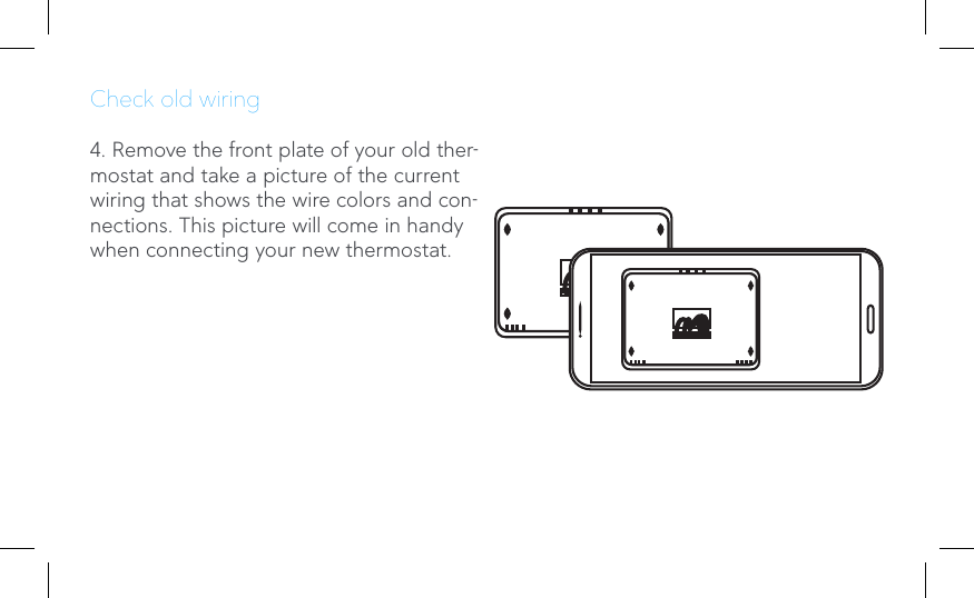
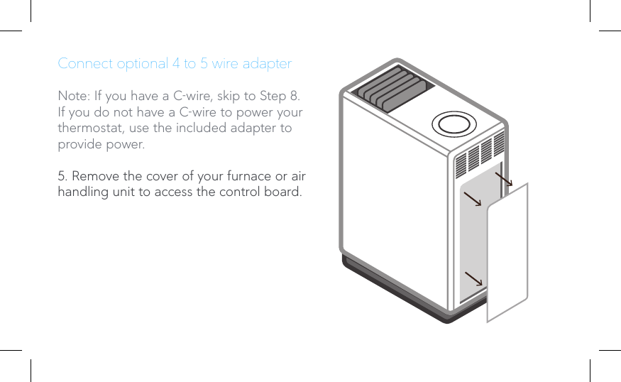
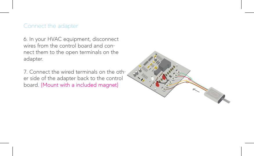
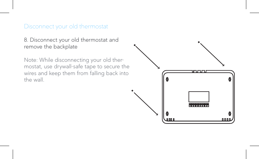
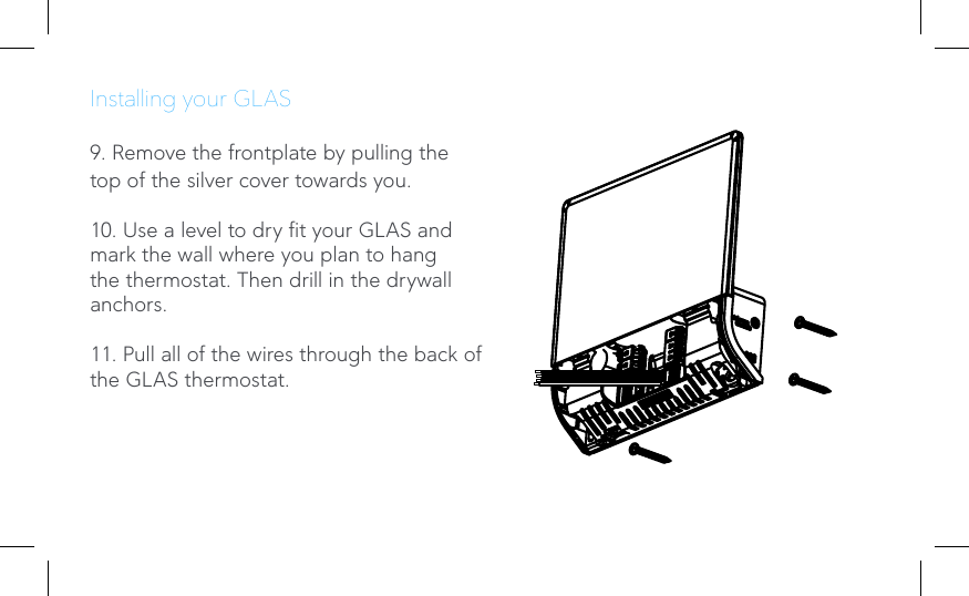
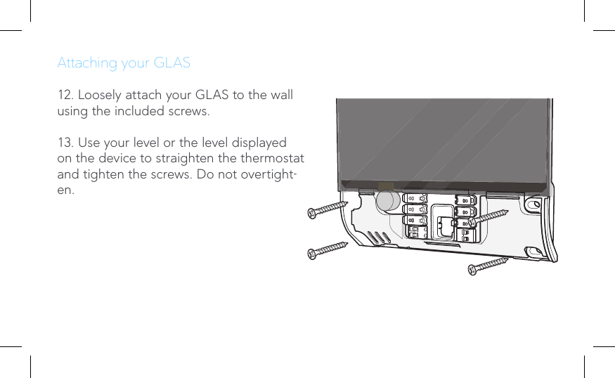
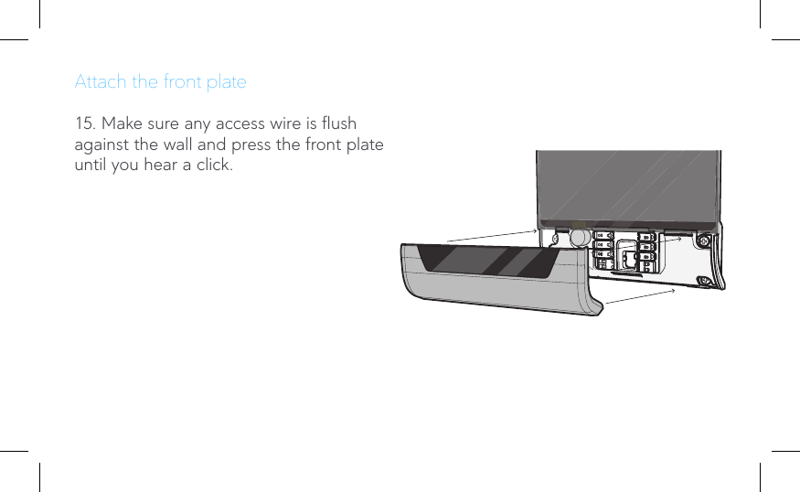
User guide
2.
Quick guide
3.
Quick start guide
User guide
Navigation menu
Upload a User Manual
Namespaces
Wiki Guide
HTML
PDF
Info
Views
User Manual
Discussion / Help
Navigation