Johnson Controls KONOZ KONOz Smart Hub Thermostat User Manual
LUX Products Corporation KONOz Smart Hub Thermostat
UserManual.wiki
>
Johnson Controls
>
KONOZ User Manual
>
User Manual
Contents
1.
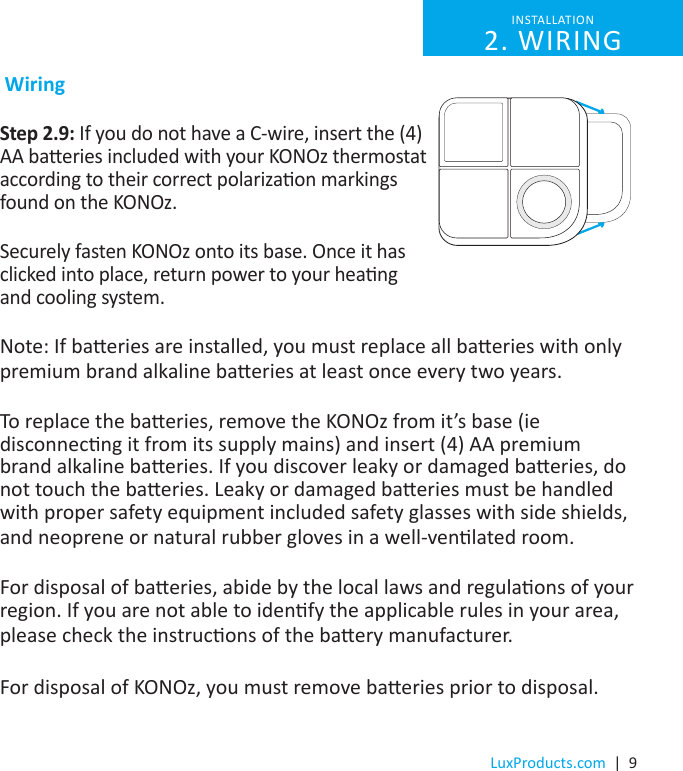
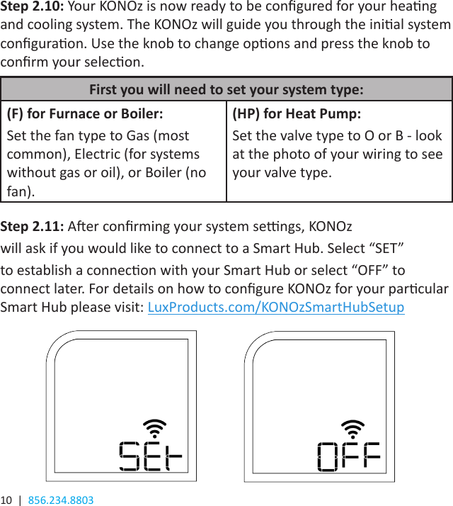
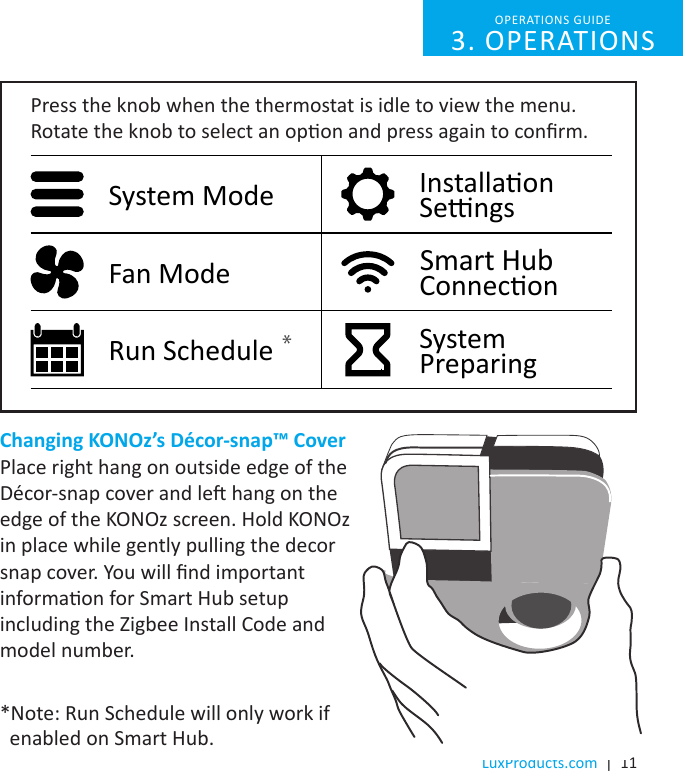
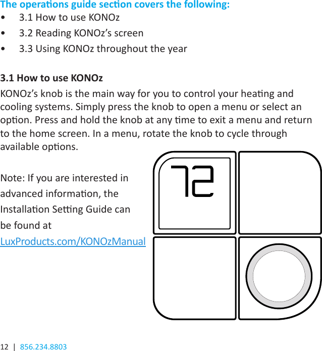
User Manual
2.
Packaging
User Manual
Navigation menu
Upload a User Manual
Namespaces
Wiki Guide
HTML
PDF
Info
Views
User Manual
Discussion / Help
Navigation