Johnson Controls KONOZ KONOz Smart Hub Thermostat User Manual
LUX Products Corporation KONOz Smart Hub Thermostat
Contents
- 1. User Manual
- 2. Packaging
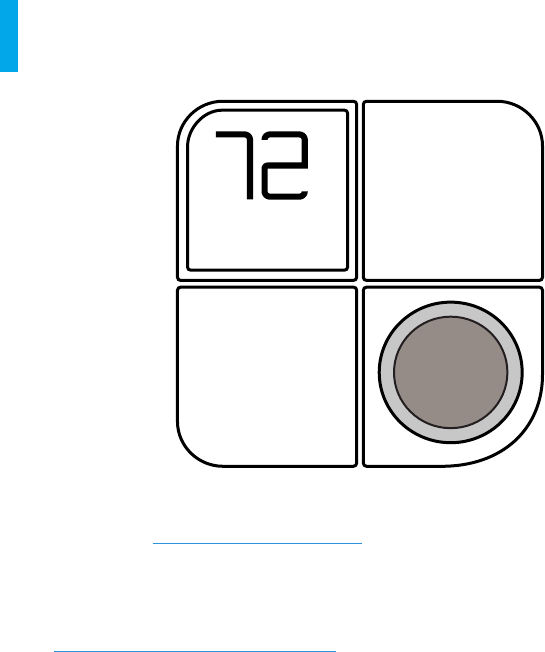
User Manual

Installaon Manual
Smart Hub
THERMOSTAT
™
Thank you for inving KONOz™ into your home. The setup process
is easy. All you need to do is follow these simple steps and you’ll
be on your way to saving energy and making your home even more
comfortable.
LUX Products oers installaon and product videos
Please visit LuxProducts.com/videos or visit our YouTube channel
LUX Products Corporaon.
Note: To contact LUX Technical Support, please call 856.234.8803.
Para ver estas instrucciones en español, por favor visite.
LuxProducts.com/KONOzmanualSP
LuxProducts.com | 3
1. START HERE
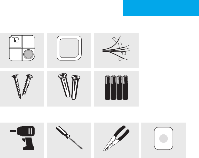
Tools Needed
Table of Contents
1. Start Here ......................................................................................2-5
2. Installing KONOz ..........................................................................6-10
3. Operang KONOz ......................................................................11-16
4. Appendix....................................................................................17-19
KONOz
Drill Oponal: Wire Stripper Smart HubPhillips Screwdriver
Baeries
What’s in the box?
Screws Wall Anchors
Trim Plate Wiring Labels
4 | 856.234.8803
This manual is a comprehensive guide for the installaon and wiring
of your KONOz thermostat.
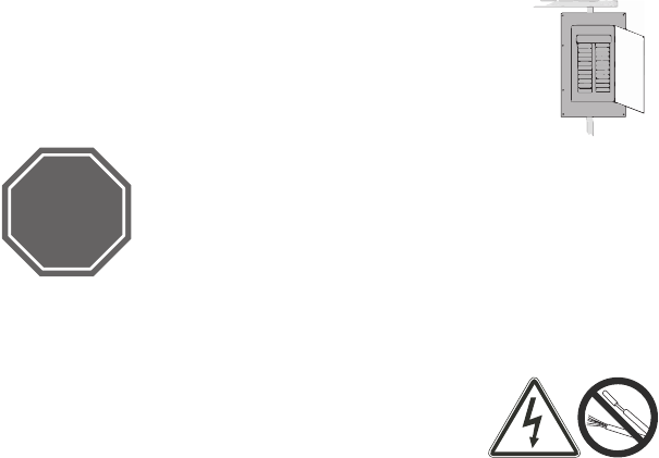
Step 1.1: Turn o the power at the circuit breaker to both
your heang and cooling systems before performing any
wiring.
Step 1.2: Conrm that your heang
and cooling system is powered down by changing the
temperature on your exisng thermostat. The heang
and cooling should not come on but may show the
temperature change on your exisng thermostat.
Note: Your system should not make any noise and you
should not feel any air exing your vents.
Step 1.3: Remove the front of your old thermostat
from its base.
If you see thick black wires, wire nuts, or any
labels that say 120-240VAC or High Voltage, your
system is not compable with KONOz . Please call
LUX Technical Support at 856.234.8803 before proceeding with your
installaon. If you do not see any high voltage labels or wires, you may
connue with the installaon process.
HIGH
VOLTAGE
STOP
LuxProducts.com | 5
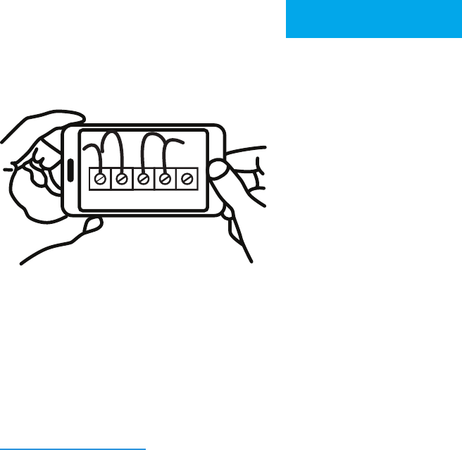
Step 1.4: Take a picture of your current wiring layout. The picture can
be used as reference later.
Step 1.5: Use the included wire labels to mark which wire is connected
to each terminal in your old thermostat.
Note: Wiring leer designaons correspond to either a “Heat Pump” or
“Convenonal” system.
Note: A wiring compatability tool is available at
LuxProducts.com/wiring
1. START HERE
6 | 856.234.8803
Wiring
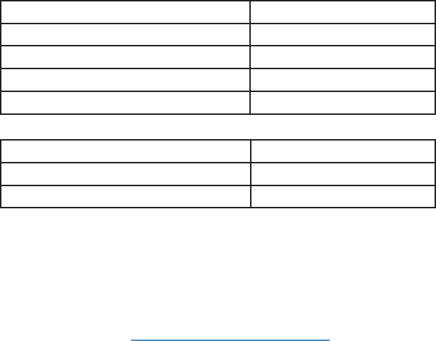
Step 2.1: Idenfy your system conguraon (see wiring diagrams in
appendix). Potenal conguraons include:
System Conguraon Wiring Conguraon
Convenonal: 1H/1C without C-wire Y, G, W1, R
Convenonal: 1H/1C with C-wire Y, G, W1, R, C
Convenonal: 2H/1C without C-wire Y, G, W1, W2, R
Convenonal: 2H/1C with C-wire Y, G, W1, W2, R, C
System Conguraon Wiring Conguraon
Heat Pump: 1H/1C with C-wire Y, G, R, O/B, C
Heat Pump with auxiliary or dual fuel: Y, G, R, O/B, W1, C
If you have only one R wire, please use the RH terminal. If you have a
dierent conguraon other than what is listed above, please call LUX
Technical Support for help with your installaon. If you have a “C” wire
then the included baeries are not needed.
Note: If you do not have a C-wire but would rather not use replaceable
baeries, please visit shop.LuxProducts.com/PowerBridge to learn more
about our Lux Power Bridge soluon.
LuxProducts.com | 7
Step 2.2: Verify that each wire has been properly labeled and remove
each wire from its terminal — make sure that they don’t fall into the
wall.
Step 2.3: Remove the mounng screws from the base of the old
thermostat and remove the base from the wall.
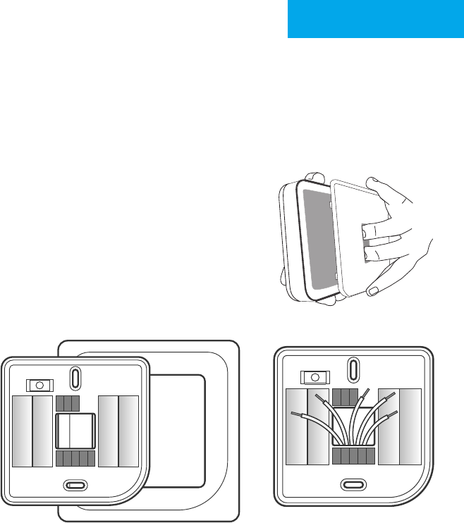
Step 2.4: Separate KONOz from its base.
Step 2.5: If you would like to use the trim
plate or wall anchors, you may install them
now.
Step 2.6: Pull the wires from your wall
through the center hole of the KONOz
base. Secure the base to the wall using the
included mounng hardware. Follow the
built in level to ensure that it is straight.
INSTALLATION
2. WIRING
Step 2.4
Step 2.5 Step 2.6
8 | 856.234.8803
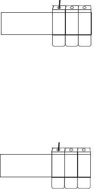
Opon 1 - Convenonal (furnace) Systems:
Step 2.7f: Follow the terminal labels
marked “Convenonal” on the thermostat
base. Press the lever and insert each
labeled wire into the top hole of the
corresponding terminal.
Step 2.8f: If you have both an RC and RH wire present, then remove the
red cap next to the reset buon. You can now proceed to step 2.9.
Opon 2 - Heat Pump Systems:
Step 2.7hp: Follow the terminal labels
marked “Heat Pump” on the thermostat base.
Referencing your wiring photo, press the
lever and insert each labeled wire into the top
hole of the corresponding terminal.
If your old thermostat did not have a W1 wire but did have a W2 wire,
insert the W2 wire into the W1 terminal.
Step 2.8hp: If you have both an O wire and a B wire
(i.e. in a Trane system), install the B wire in the “C” terminal.
For more detailed direcons, please see the wiring diagrams in the
appendix or call LUX Technical Support.
CONVENTIONAL C Y1 W2
HEAT PUMP C Y1 O/B
POWER BRIDGE 4
CONVENTIONAL C Y1 W2
HEAT PUMP C Y1 O/B
POWER BRIDGE 4
LuxProducts.com | 9
Wiring
Step 2.9: If you do not have a C-wire, insert the (4)
AA baeries included with your KONOz thermostat
according to their correct polarizaon markings
found on the KONOz.
Securely fasten KONOz onto its base. Once it has
clicked into place, return power to your heang
and cooling system.
Note: If baeries are installed, you must replace all baeries with only
premium brand alkaline baeries at least once every two years.
To replace the baeries, remove the KONOz from it’s base (ie
disconnecng it from its supply mains) and insert (4) AA premium
brand alkaline baeries. If you discover leaky or damaged baeries, do
not touch the baeries. Leaky or damaged baeries must be handled
with proper safety equipment included safety glasses with side shields,
and neoprene or natural rubber gloves in a well-venlated room.
For disposal of baeries, abide by the local laws and regulaons of your
region. If you are not able to idenfy the applicable rules in your area,
please check the instrucons of the baery manufacturer.
For disposal of KONOz, you must remove baeries prior to disposal.
INSTALLATION
2. WIRING
10 | 856.234.8803
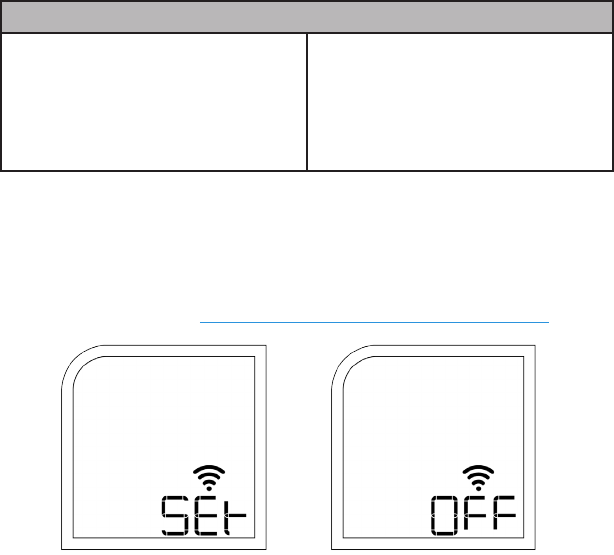
Step 2.11: Aer conrming your system sengs, KONOz
will ask if you would like to connect to a Smart Hub. Select “SET”
to establish a connecon with your Smart Hub or select “OFF” to
connect later. For details on how to congure KONOz for your parcular
Smart Hub please visit: LuxProducts.com/KONOzSmartHubSetup
(F) for Furnace or Boiler:
Set the fan type to Gas (most
common), Electric (for systems
without gas or oil), or Boiler (no
fan).
(HP) for Heat Pump:
Set the valve type to O or B - look
at the photo of your wiring to see
your valve type.
First you will need to set your system type:
Step 2.10: Your KONOz is now ready to be congured for your heang
and cooling system. The KONOz will guide you through the inial system
conguraon. Use the knob to change opons and press the knob to
conrm your selecon.
LuxProducts.com | 11
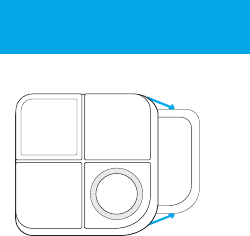
Changing KONOz’s Décor-snap™ Cover
Place right hang on outside edge of the
Décor-snap cover and le hang on the
edge of the KONOz screen. Hold KONOz
in place while gently pulling the decor
snap cover. You will nd important
informaon for Smart Hub setup
including the Zigbee Install Code and
model number.
*Note: Run Schedule will only work if
enabled on Smart Hub.
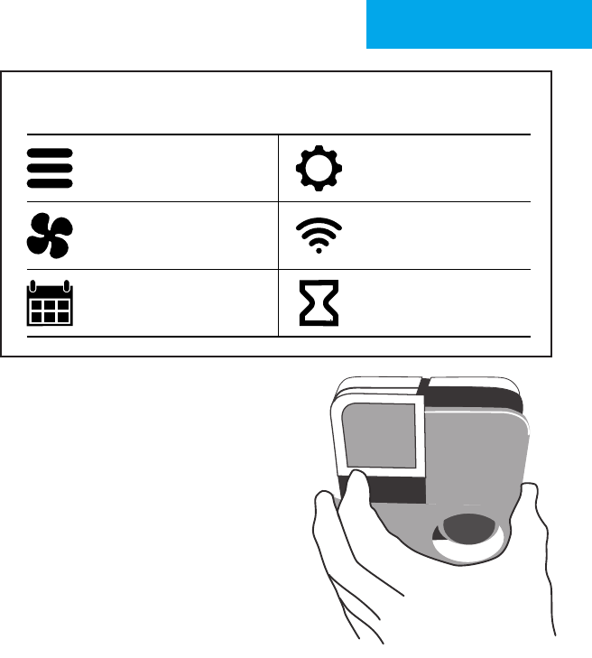
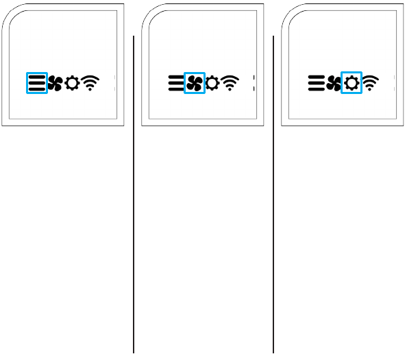
Press the knob when the thermostat is idle to view the menu.
Rotate the knob to select an opon and press again to conrm.
Press the knob when the thermostat is idle to
view the menu. Rotate the knob to select an
opon and press again to conrm.
System Mode Installaon
Sengs
Fan Mode Network
Connecon
Run Schedule System
Preparing
For more informaon about
installaon sengs, please visit
LuxProducts.com/KONOmanual
OPERATIONS GUIDE
3. OPERATIONS
Smart Hub
*
12 | 856.234.8803
The operaons guide secon covers the following:
• 3.1 How to use KONOz
• 3.2 Reading KONOz’s screen
• 3.3 Using KONOz throughout the year
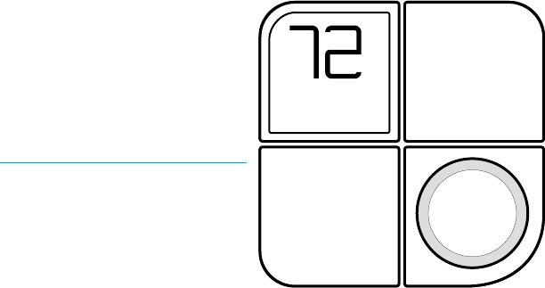
3.1 How to use KONOz
KONOz’s knob is the main way for you to control your heang and
cooling systems. Simply press the knob to open a menu or select an
opon. Press and hold the knob at any me to exit a menu and return
to the home screen. In a menu, rotate the knob to cycle through
available opons.
Note: If you are interested in
advanced informaon, the
Installaon Seng Guide can
be found at
LuxProducts.com/KONOzManual
LuxProducts.com | 13
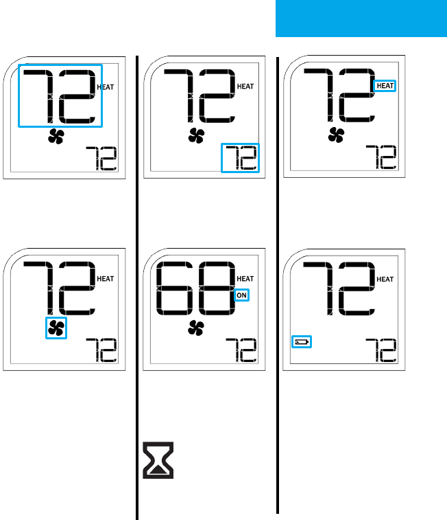
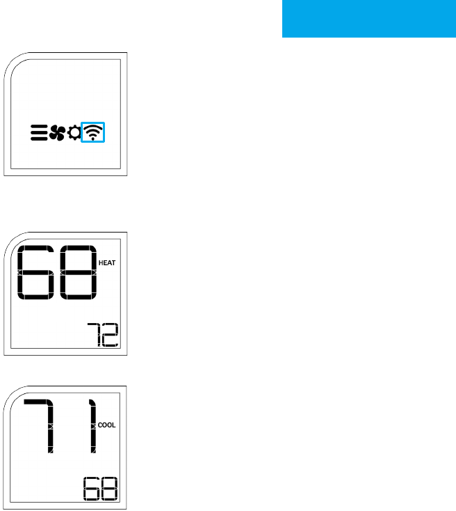
3.2 Reading KONOz’s screen
The large number in
the top le shows
your ambient room
temperature.
The small number in the
boom right shows your
set temperature.
The selected system
mode (HEAT, COOL or
OFF) is shown to the right
of the ambient room
temperature.
The acve fan status
is shown by the icon
below the ambient
room temperature. If
it is o, your fan is not
running. If it is on, your
fan is running. Please
note that your fan will
run depending on your
selected fan mode (either
AUTO or ON).
If you see ON under
your system mode, it
means that your system
is acvely heang or
cooling your home.
This icon indicates the
baery levels of the
KONOz.
Note: Replace all four AA
baeries in the KONOz if the
low baery icon or blinking
empty baery icon appears
on your KONOz.
OPERATIONS GUIDE
3. OPERATIONS
This icon shows that
your HVAC system is
preparing to turn on
or o. Please wait for
heang and cooling
to start.
14 | 856.234.8803
Reading KONOz’s screen
This icon opens the
system mode menu.
In this menu, you can
set your HVAC system
to OFF, HEAT, or COOL.
Your thermostat will
automacally detect
which modes are
available when you install
your thermostat, so you
may not see all three
opons depending on
your system type.
This icon opens the
fan mode menu. In
this menu, you can set
your fan to AUTO, or
ON. AUTO will run your
fan when your system
is acvely heang or
cooling. ON will run your
fan connuously. If you
set a lter life value in
the installaon sengs,
you’ll be able to check
the remaining life of your
lter in the fan sengs
menu.
This icon opens the
installaon sengs
menu. In this menu, you
can adjust advanced
preferences for special
applicaons. Select the
gear icon, then aer IS
appears on the screen,
select YES to begin the
installaon sengs ow.
For more informaon
about the installaon
sengs, please view the
“Installaon Sengs
Guide”.
LuxProducts.com | 15
This icon opens the Smart Hub network
connecon menu. In this menu, you can choose
to connect or disconnect from your Smart Hub.
Select “SET” to establish a new Smart Hub
connecon. Select “OFF” to temporarily disable
the connecon. Lastly, select “ON” to reconnect
to your Smart Hub. For more informaon
about connecng to a Smart Hub, please view
KONOz’s Smart Hub Setup Guide.
3.3 Using KONOz throughout the year
Cold Weather:
Heat mode is the best seng to use when it’s
cold out and you won’t need to use your air
condioner. This will make sure that your air
condioner stays idle and that your heater
keeps your home’s temperature above your
chosen set-temperature.
Hot Weather:
Cool mode is the best seng to use when it’s
hot out and you won’t need to use your heang
system. This will make sure that your heater
stays idle and that your air condioner keeps
your home’s temperature below your chosen
set-temperature.
OPERATIONS GUIDE
3. OPERATIONS

16 | 856.234.8803
Congratulaons!
Installaon is complete and your KONOz is ready to go. Now let’s save
some energy and make your home more comfortable.
Personalize your KONOz.
It’s more than a thermostat, it’s décor! Match KONOz to your style by
simply changing the Décor-snap cover. Check out our wide variety of
designer colors and nishes at LuxProducts.com/ShopCovers
Hibiscus
Red Sea
Green Deep
Blue True
White
Midnight
Black
Sky
Blue Sea Mist
Grey Champagne
Gold Paint
It
Driwood
LuxProducts.com | 17
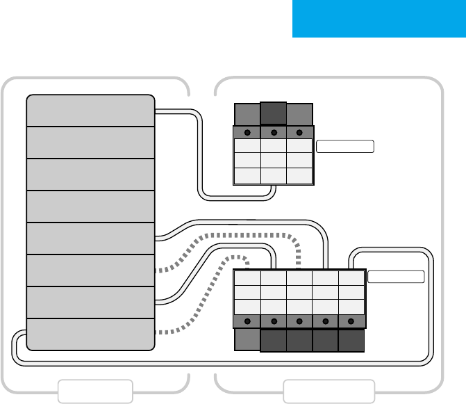
Convenonal System
Notes:
• C-wire oponal
• The W2 terminal is used for 2 stage heang
• If you have both an RH and RC wire, please remove the red cap from the back of
the thermostat
4. APPENDIX
RC
RC
G
G
1
C
C
4
Y1
Y1
W2
O/B
W1
W1
2
RH
RH
3
Conventional
Heat Pump
Power Bridge
Conventional
Heat Pump
Power Bridge
Furnace Thermostat
Fan
Heat (Stage 1)
Heat (Stage 2)
Cool
Transformer
18 | 856.234.8803
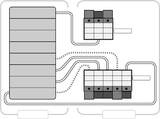
Heat Pump System
Notes:
• C-wire oponal
• The W1 terminal is used for Auxiliary/Emergency heat or on Dual Fuel systems
RC
RC
G
G
1
C
C
4
Y1
Y1
W2
O/B
W1
W1
2
RH
RH
3
Conventional
Heat Pump
Power Bridge
Conventional
Heat Pump
Power Bridge
Fan
AUX/Emer Heat
Changeover Valve
Compressor
Transformer
Heat Pump Thermostat

LuxProducts.com | 19
4. APPENDIX
Technical Informaon:
Disconnecon Means: Type 1B
Polluon Degree: 2
Impulse Voltage: 330V
Automac Acon: 100,000 cycles
Electrical Rang:
-Input: 24V a.c. 60Hz or 4xAA Alkaline baery
-Output: @24V a.c. Max. 1.5A
FCC Part 15C
Warning: Changes or modicaons to this unit not expressly approved by the party responsible for compliance
could void the user’s authority to operate the equipment.NOTE: This equipment has been tested and found to
comply with the limits for a Class B digital device, pursuant to Part 15 of the FCC Rules. These limits are designed to
provide reasonable protecon against harmful interference in a residenal installaon. This equipment generates,
uses and can radiate radio frequency energy and, if not installed and used in accordance with the instrucons, may
cause harmful interference to radio communicaons.
However, there is no guarantee that interference will not occur in a parcular installaon.If this equipment does
cause harmful interference to radio or television recepon, which can be determined by turning the equipment o
and on, the user is encouraged to try to correct the interference by one or more of the following measures:
• Reorient or relocate the receiving antenna.
• Increase the separaon between the equipment and receiver.
• Connect the equipment into an outlet on a circuit dierent from that to which the receiver is connected.
• Consult the dealer or an experienced radio/TV technician for help.
This device complies with Part 15 of the FCC Rules. Operaon is subject to the following two condions:
(1) This device may not cause harmful interference, and (2) this device must accept any interference received,
including interference that may cause undesired operaon. FCC RF Radiaon Exposure Statement
Cauon: To maintain compliance with the FCC’s RF exposure guidelines, place the unit at least 20cm from nearby
persons.
RSS-247
This device complies with Industry Canada licence-exempt RSS standard(s). Operaon is subject to the following two
condions: (1) this device may not cause interference, and (2) this device must accept any interference, including
interference that may cause undesired operaon of the device.
Le présent appareil est conforme aux CNR d’Industrie Canada applicables aux appareils radio exempts de licence.
L’exploitaon est autorisée aux deux condions suivantes: (1) l’appareil ne doit pas produire de brouillage, et (2)
l’ulisateur de l’appareil doit accepter tout brouillage radioélectrique subi, même si le brouillage est suscepble d’en
compromere le fonconnement.

LUX PRODUCTS CORPORATION
Philadelphia, PA 19112 USA
LuxProducts.com
Designed in Philadelphia.
53620