Johnson and Johnson Surgical Vision SIGACPM2 Advanced Control Pedal Master User Manual User s Manual 2
Abbott Medical Optics Advanced Control Pedal Master User s Manual 2
Contents
- 1. User manual 1
- 2. User Manual 2
User Manual 2
5 • Anterior Segment Surgery Operating Modes
WHITESTAR SIGNATURE™ System Rx Only – Z370147 Rev. C 1008 5-39
3. Press Finished to close the window.
Low Power Pulse Phaco Power
Low Power Pulse generates short pulses of ultrasonic power in footpedal Position
3. When you press the footpedal, the pulses become longer and eventually blend
together to become continuous phaco power.
High Power Pulse Phaco Power
High Power Pulse generates continuous Phaco Power in footpedal Position 3.
When you press the footpedal, the continuous pulse changes into long pulses and
then gradually changes to short pulses.
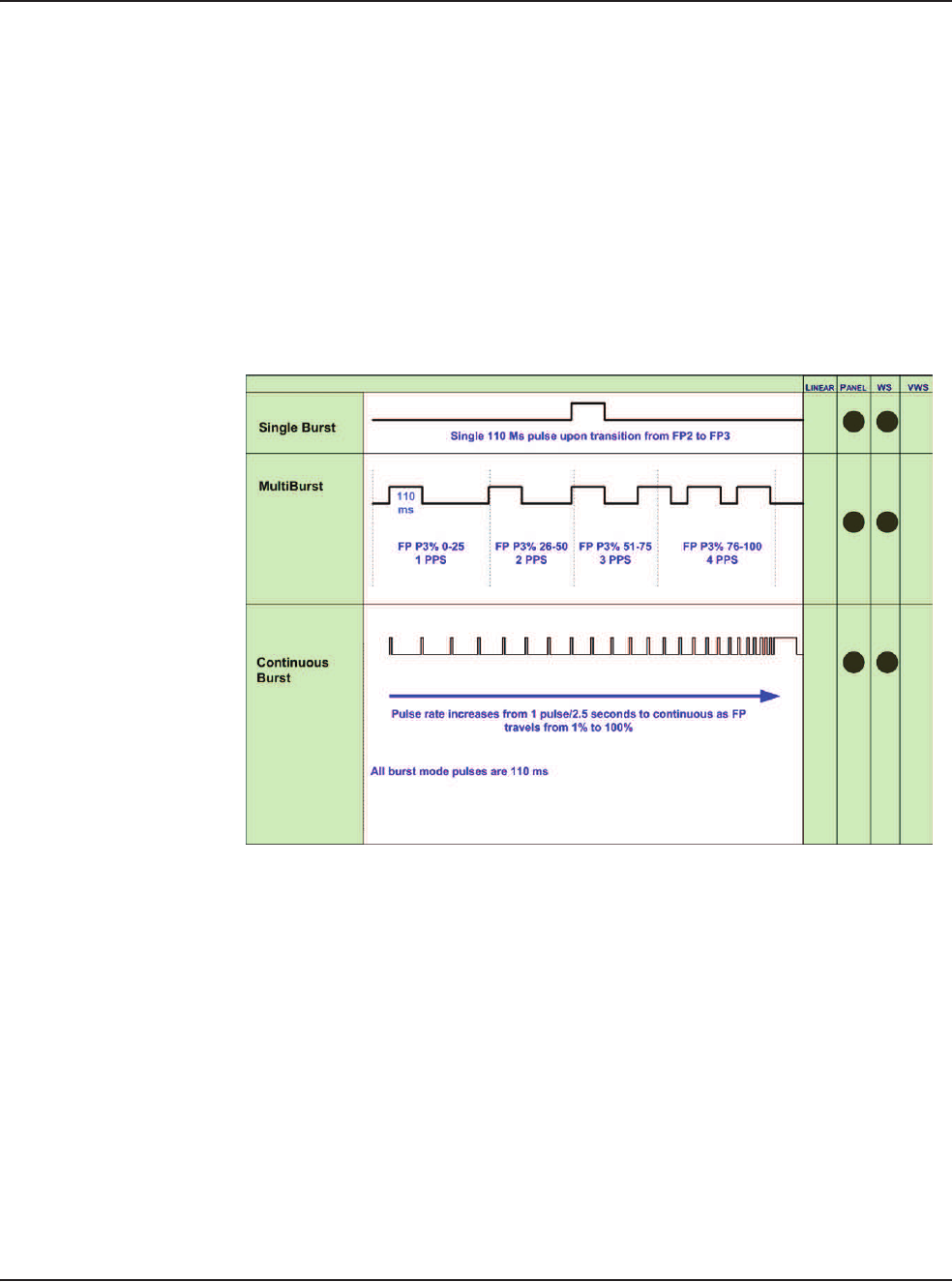
Figure 5.31 – AMO™ Phaco Burst Power Modes
Single Burst Phaco Power (Panel Only)
Single Burst delivers a single burst of ultrasonic power of 110 ms duration when
you press the footpedal to Position 3. You must return to footpedal Position 2,
pause for approximately one-half (.5) second, and then press the footpedal to
Position 3 to obtain an additional burst of energy.
Multiple Burst Phaco Power (Panel Only)
Multiple Burst generates a burst of ultrasonic power of 110 ms duration, with
additional bursts deployed beginning at approximately 1 burst per second when you
press the footpedal to Position 3.
The frequency of burst increases as you press the footpedal. At the maximum level
of footpedal Position 3, the bursts are delivered at the rate of 4 bursts per second.
5 • Anterior Segment Surgery Operating Modes
WHITESTAR SIGNATURE™ System Rx Only – Z370147 Rev. C 1008 5-40
Continuous Burst Phaco Power (Panel Only)
Continuous Burst delivers a 110 ms ultrasonic burst duration. As you press the
footpedal through Position 3, the bursts get closer together. At the maximum level
of footpedal Position 3, the bursts blend together, and the power becomes
continuous (at the preset power level).
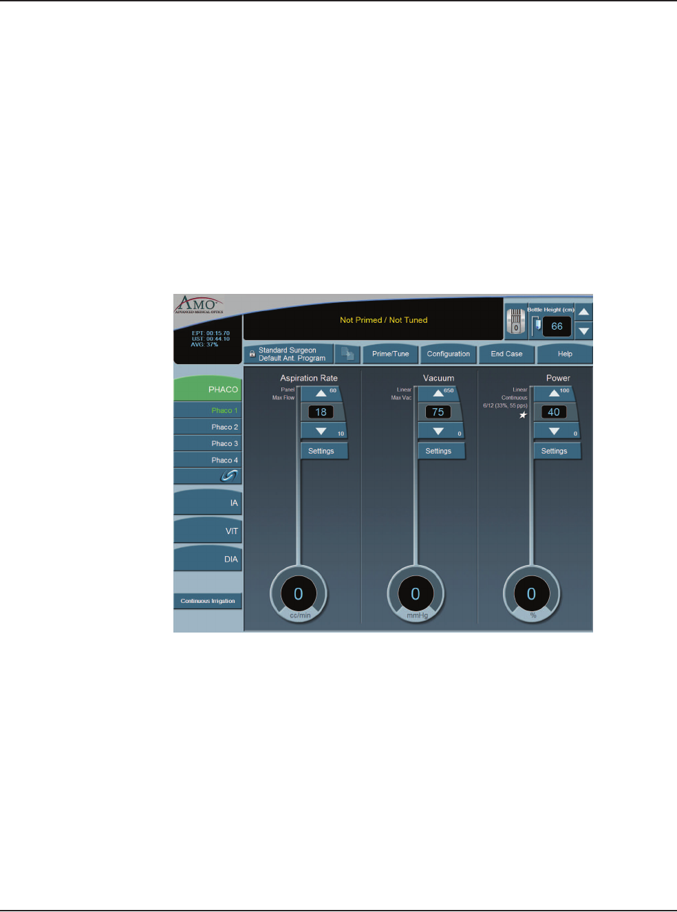
Override PHACO Submode Settings
You can override the settings for a PHACO submode by selecting the submode,
and either press the Up and Down arrows to increase or decrease Aspiration Rate,
Vacuum, or Power settings, or press Settings on the control panels for Aspiration
Rate, Vacuum, or Power. If you pressed the Settings button, the Settings pop-up
window appears.
Figure 5.32 – Override PHACO Submode Settings
5 • Anterior Segment Surgery Operating Modes
WHITESTAR SIGNATURE™ System Rx Only – Z370147 Rev. C 1008 5-41
OCCLUSION
MODE™ Phaco
Settings
CASE Mode
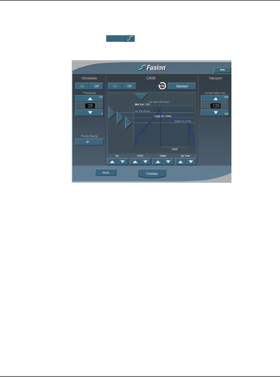
To access the OCCLUSION MODE™ Phaco and CASE settings:
1. Press the button from the PHACO operating screen.
Figure 5.33 – CASE OCCLUSION MODE™ Phaco
CASE maintains a stable chamber by detecting an impending occlusion break, and
reducing the vacuum before occlusion surge can occur. When the occlusion is
detected, the System waits long enough to allow the particle to be firmly grasped,
and then reduces the vacuum to a lower level in order to allow the occlusion to be
safely cleared. When the occlusion is fully cleared, the vacuum returns to the
previous vacuum level.
5 • Anterior Segment Surgery Operating Modes
WHITESTAR SIGNATURE™ System Rx Only – Z370147 Rev. C 1008 5-42
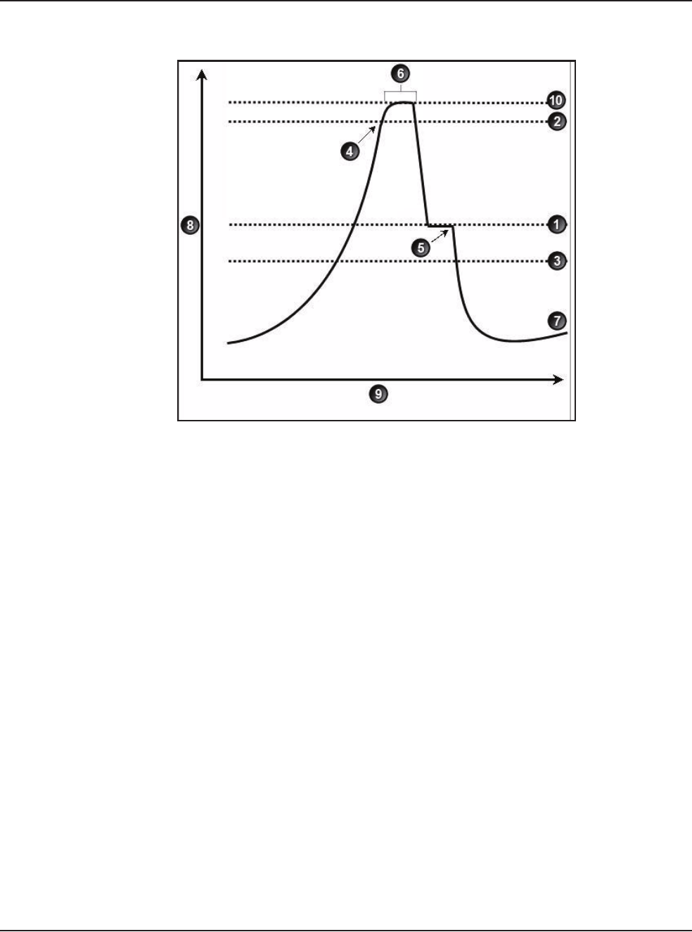
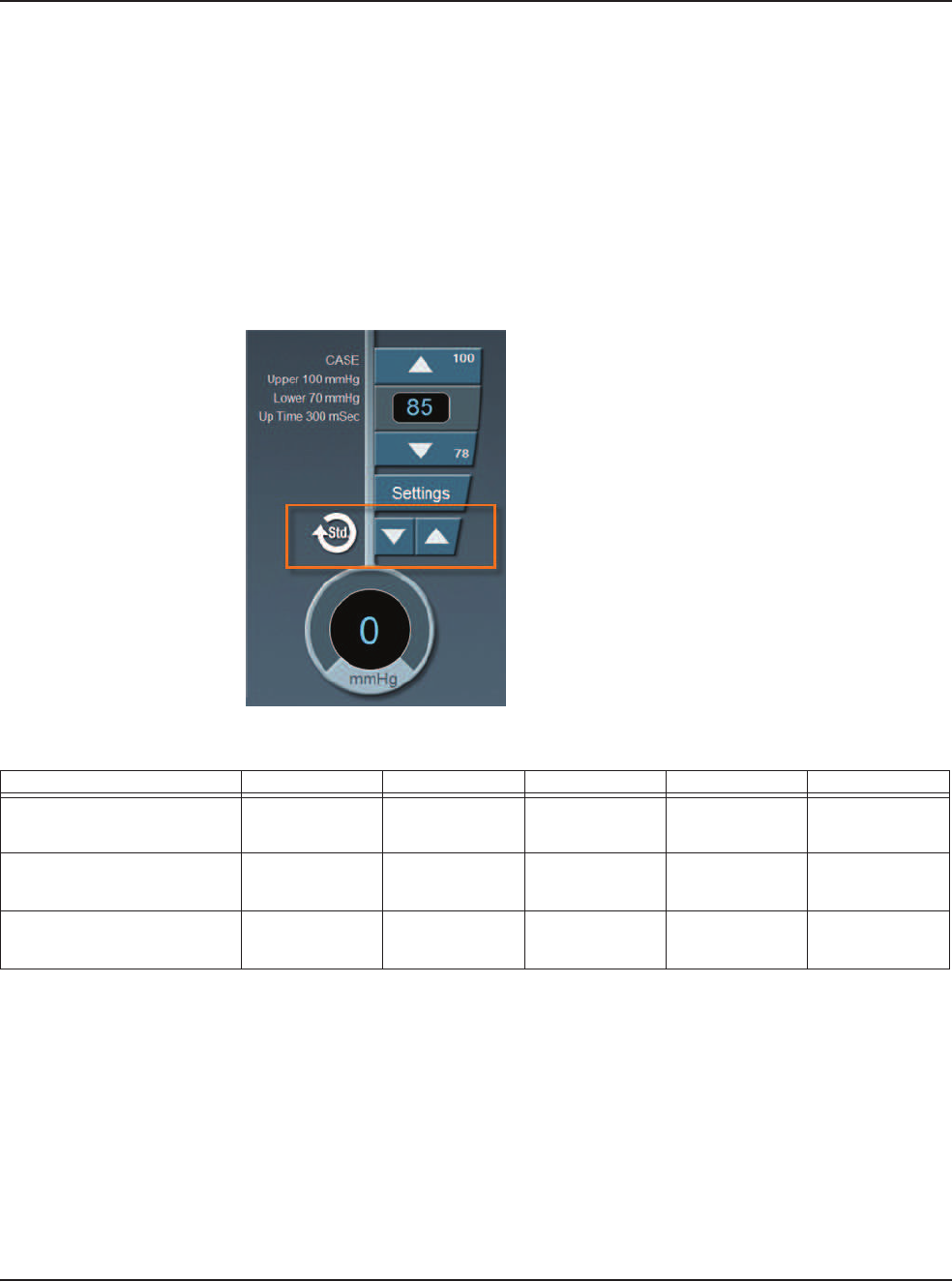
Figure 5.34 – CASE OCCLUSION MODE™ Phaco
You can control and customize the CASE behavior by setting the:
1. Upper and Lower Vacuum Threshold levels
2. CASE Vacuum Level
3. “Up Time” delay, which determines the maximum time that the Upper
Threshold Vacuum level is maintained.
1. CASE Vacuum 6. Up Time
2. Upper Threshold 7. Vacuum Level
3. Lower Threshold 8. Vacuum
4. Vacuum Level crosses Upper Threshold 9. Time
5. Phaco activated 10. Max Vac
5 • Anterior Segment Surgery Operating Modes
WHITESTAR SIGNATURE™ System Rx Only – Z370147 Rev. C 1008 5-43
CASE One Touch
To simplify the programming of the CASE function, you only need to define the
basic CASE parameters once. The CASE function can then be adjusted quickly and
simply from the CASE One Touch settings on the surgical screen. Using these
controls, the CASE functionality can be changed to provide greater efficiency (Up
arrow) or provide more control (Down arrow) to suit any particular combination of
cataract density, surgical technique or personal preference.
When CASE is On, use the One Touch buttons to adjust the CASE parameters.
Figure 5.35 – CASE One Touch
Table 5.10 – CASE One Touch Parameter Settings
Parameter CASE -2 CASE -1 CASE STD CASE +1 CASE +2
Pump Ramp Setting Program
default
Program
default
Program
default
CASE STD
+10%
CASE STD
+20%
CASE Occlusion Delay CASE STD
-200 ms
CASE STD
-100 ms
Program
default
CASE STD
+100 ms
CASE STD
+200 ms
CASE Upper
Threshold
CASE STD
-5%
Program
default
Program
default
Program
default
CASE STD
+5%
5 • Anterior Segment Surgery Operating Modes
WHITESTAR SIGNATURE™ System Rx Only – Z370147 Rev. C 1008 5-44
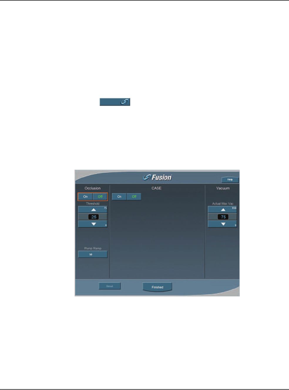
OCCLUSION MODE™ Phaco Settings
You can set different Aspiration Rates for occluded aspiration as opposed to
unoccluded aspiration.
With the OCCLUSION MODE™ Phaco you can set a different vacuum rise time
when the phaco tip is occluded without changing the aspiration rate through an
unoccluded needle.
To set the Occluded Aspiration Rate thresholds:
1. Press PHACO.
2. Press on the left of the screen. Three new control panels appear for
Aspiration and Power. The center panel is for a graphical display of the CASE
settings.
3. Press On to set the thresholds.
4. Change the settings in the new control panels as needed.
5. Press Finished to close the window.
Figure 5.36 – OCCLUSION MODE™ Phaco
6. Press Finished to close the screen.
5 • Anterior Segment Surgery Operating Modes
WHITESTAR SIGNATURE™ System Rx Only – Z370147 Rev. C 1008 5-45
Occlusion Vacuum Threshold
In OCCLUSION MODE™ Phaco, you can set an occluded threshold value for
vacuum.
When in OCCLUSION MODE™ Phaco, there is an additional control panel for
Vacuum. The Vacuum Threshold setting lets you choose the vacuum level at which
occluded settings take effect.
To adjust the Occluded Vacuum Threshold:
1. Press the Up or Down arrows, in Occlusion mode, to increase or decrease the
Occluded Vacuum Threshold.
2. When the threshold is decreased, the occlusion settings take effect sooner.
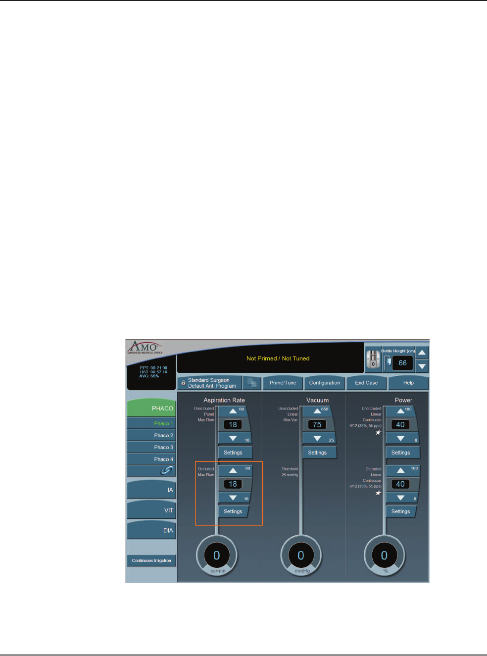
Occlusion Aspiration Rate
In OCCLUSION MODE™ Phaco, you can set a different Max Flow value for
aspiration. There is an additional control panel for aspiration below the standard
aspiration control panel.
To adjust the occluded aspiration rate:
1. In OCCLUSION MODE™ Phaco, press the Up or Down arrows to increase or
decrease the occluded aspiration rate.
Figure 5.37 – Occlusion Aspiration Rate
Or
2. Press Settings. The Occluded Aspiration Rate pop-up window appears.
5 • Anterior Segment Surgery Operating Modes
WHITESTAR SIGNATURE™ System Rx Only – Z370147 Rev. C 1008 5-46
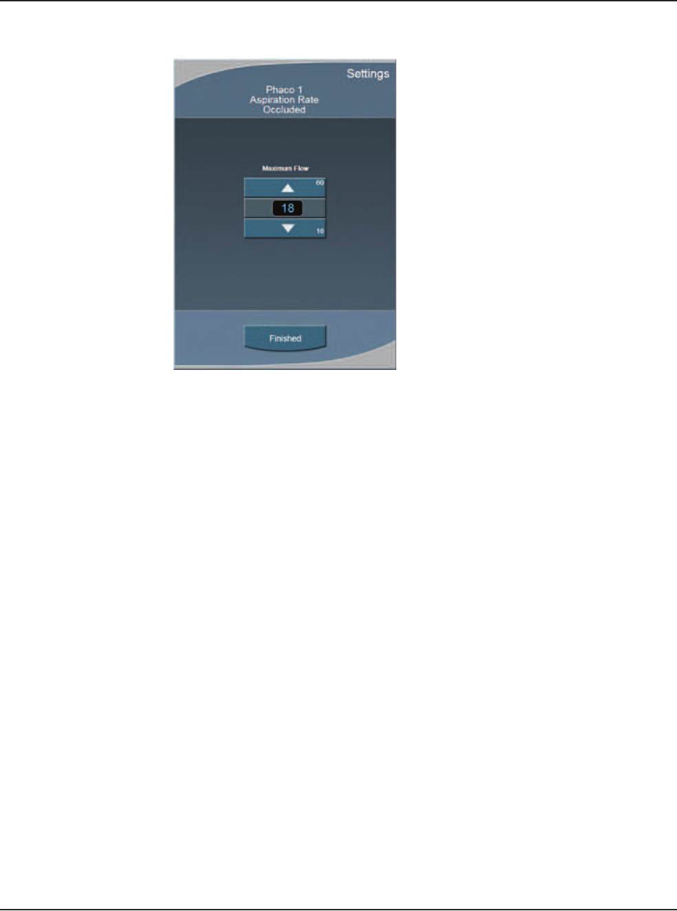
Figure 5.38 – Occluded Aspiration Rate Pop-up Window
3. Press the Up or Down arrows to increase or decrease the occluded aspiration
rate.
4. Press Finished to close the window.
5 • Anterior Segment Surgery Operating Modes
WHITESTAR SIGNATURE™ System Rx Only – Z370147 Rev. C 1008 5-47
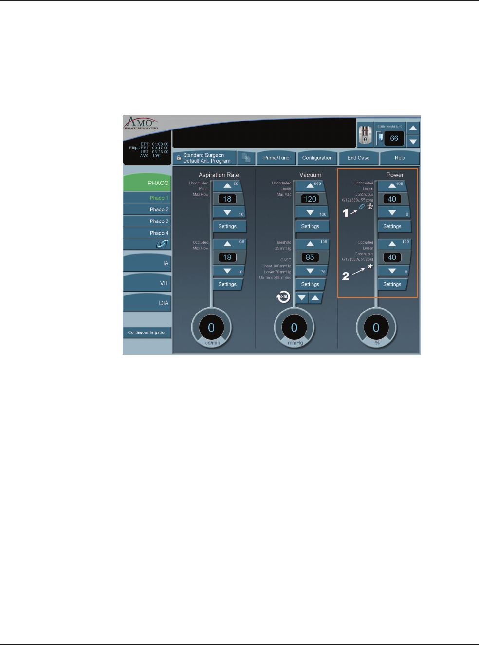
OCCLUSION MODE™ Phaco Power Settings
You can set different power levels when the phaco tip is occluded.
When you are in OCCLUSION MODE™ Phaco, there is an additional control
panel for Power.
Figure 5.39 – OCCLUSION MODE™ Phaco Power Settings
To adjust the occluded power delivery:
1. In OCCLUSION MODE™ Phaco, press the Up or Down arrows to increase or
decrease the occluded power level.
2. Press Settings to change other power settings. A Power Settings screen opens.
3. Press Linear or Panel. Depending on whether you select Linear or Panel,
there are a total of nine different power settings you can choose.
4. Press the buttons on the right of the Settings screen to select a power delivery
value.
5. Press the On button to engage WHITESTAR® Technology.
6. Press Finished to close the screen.
Venting an Occlusion
When the aspiration port is blocked or occluded by tissue or other material, the
vacuum pressure builds up. The aspiration flow system vents to the bottle when the
footpedal is released. Another choice is that you can release the footpedal to
Position 1 and that causes the aspiration system fluid to vent using pump rotation.
1. WHITESTAR® Technology with Pulse Shaping with Ellips™ Technology
2. WHITESTAR® Technology without Pulse Shaping
5 • Anterior Segment Surgery Operating Modes
WHITESTAR SIGNATURE™ System Rx Only – Z370147 Rev. C 1008 5-48
These methods release the material at the aspiration port and gives you full control
if the tip accidentally grabs the capsule or iris. The internal fluidic system allows
the desired vacuum level to be maintained when you hold the footpedal at a
constant position. The two adjustments associated with aspiration flow are Max
Vac and Max Flow.
Passive Reflux You can select from either Yes or No. The Yes reverses the pump to vent. The No
option opens a path to the bottle pressure and allows reflux into the eye.
1. Select Configuration.
2. Select Surgeons and Programs.
3. Select the applicable operating mode and submode.
4. Press the Passive Reflux button to select either Yes or No. The system default
is Yes.
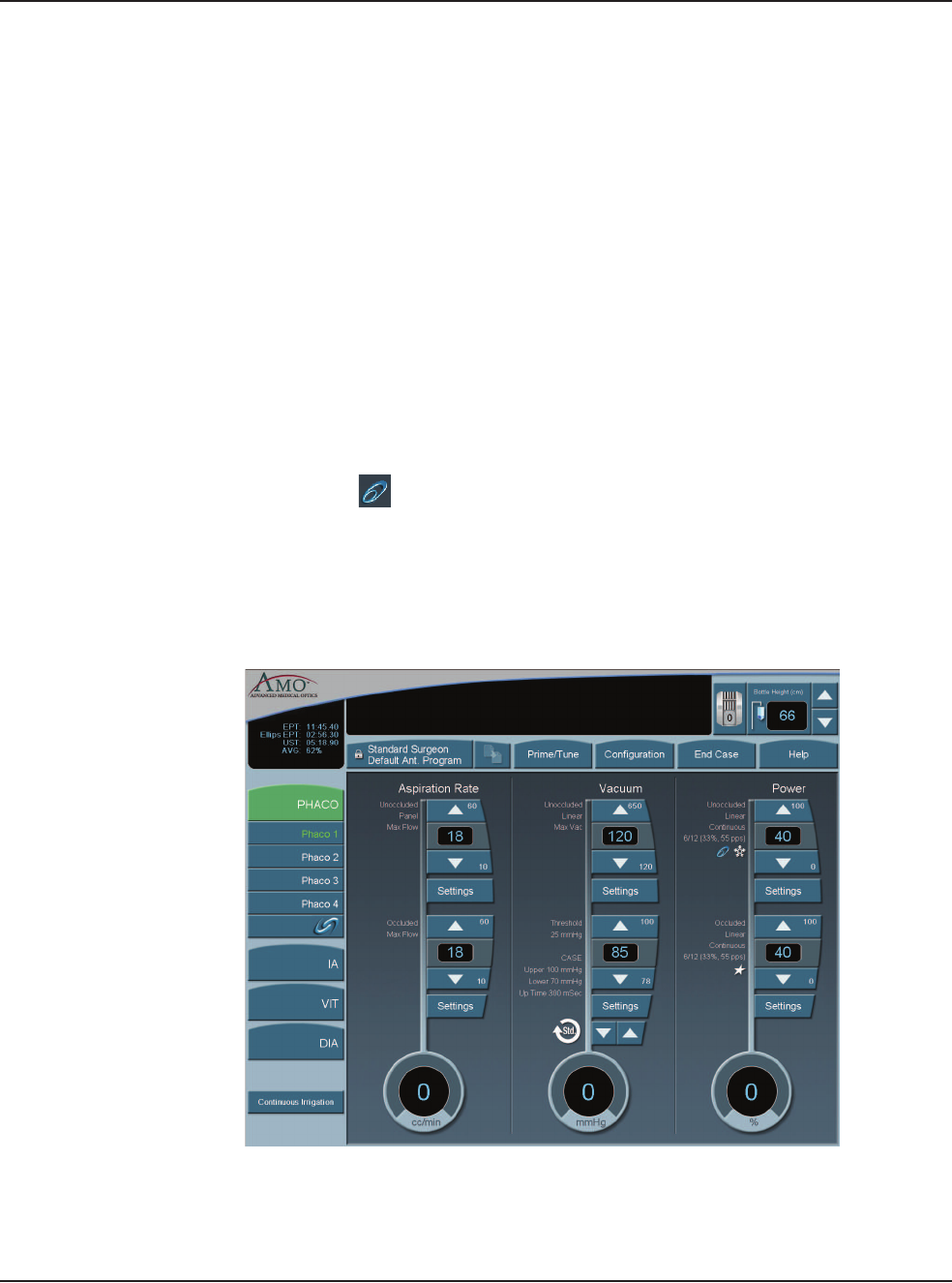
Ellips™ Technology Press the Ellips™ Technology button on the Phaco Power Settings screen to
activate. The is shown on the Phaco operating mode screen when Ellips™
Technology is on. Ellips™ Technology can be set for each Phaco submode.
Note: You must have an Ellips™ Phaco handpiece attached to the system before
you can activate the Ellips™ Technology.
Figure 5.40 – Phaco with Ellips™ Technology

WHITESTAR SIGNATURE™ System Rx Only – Z370147 Rev. C 1008 6-1
Select Surgeon/Program
Add a New Surgeon
Edit a Surgeon
Select a Preferred Program
Create a New Program
Edit a Surgeon Program
Copy a Surgeon Program
Delete a Surgeon
Delete a Program
Delete a Database
Lock a Program
Program – Assign Order
6SURGEON PROGRAMS
6 • Surgeon Programs
WHITESTAR SIGNATURE™ System Rx Only – Z370147 Rev. C 1008 6-2
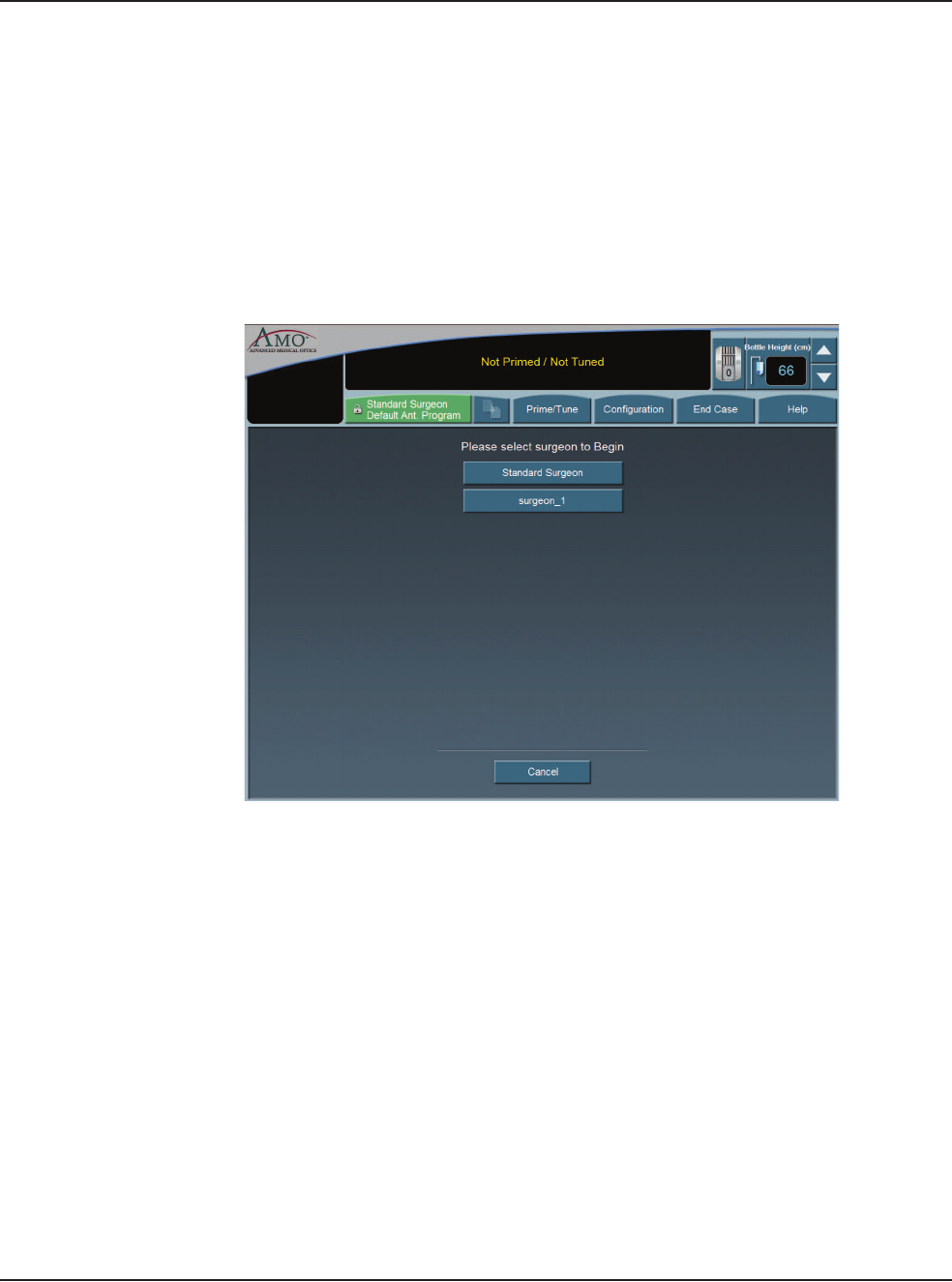
Select Surgeon/
Program
1. When the System completes the Self Test routine, you are prompted by the
System to select a Surgeon (by name). If there are no surgeons defined on the
system this screen is not shown.
Note: If your name is not listed, you can use Standard Surgeon, the AMO
default surgeon setup, and then save those settings to your name.
2. After you select a surgeon, the System prompts you to select a Surgeon
Program. If there are no programs defined on the system, the Select A
Surgeon Program screen is not shown.
Figure 6.1 – Select Surgeon Window
6 • Surgeon Programs
WHITESTAR SIGNATURE™ System Rx Only – Z370147 Rev. C 1008 6-3
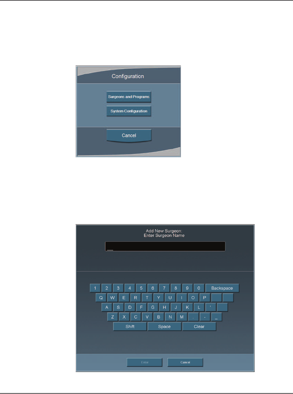
Add a New Surgeon To create a new Surgeon program:
1. Press Configuration.
2. Press Surgeons and Programs.
Figure 6.2 – Configuration Pop-up Window
3. The Program Settings screen opens.
4. Press Add New Surgeon. The Keyboard window opens.
5. Enter the name of the surgeon.
6. Press Enter to save the new surgeon and exit the Keyboard window. The new
Surgeon now appears in the list of available surgeons.
Figure 6.3 – Keyboard Screen
6 • Surgeon Programs
WHITESTAR SIGNATURE™ System Rx Only – Z370147 Rev. C 1008 6-4
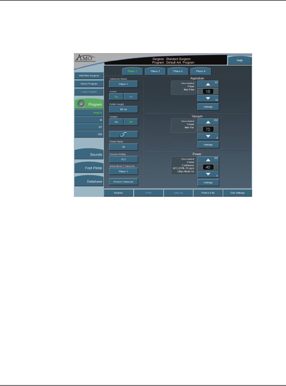
7. Edit the settings for this surgeon on the Program Settings screen. Use the
Copy Program to copy another surgeon's program. Refer to Copy a Surgeon
Program in this chapter.
Figure 6.4 – PHACO Submode Settings
6 • Surgeon Programs
WHITESTAR SIGNATURE™ System Rx Only – Z370147 Rev. C 1008 6-5
8. Press SAVE. If you do not edit any of the settings you can only use Save As.
9. Press Exit Settings.
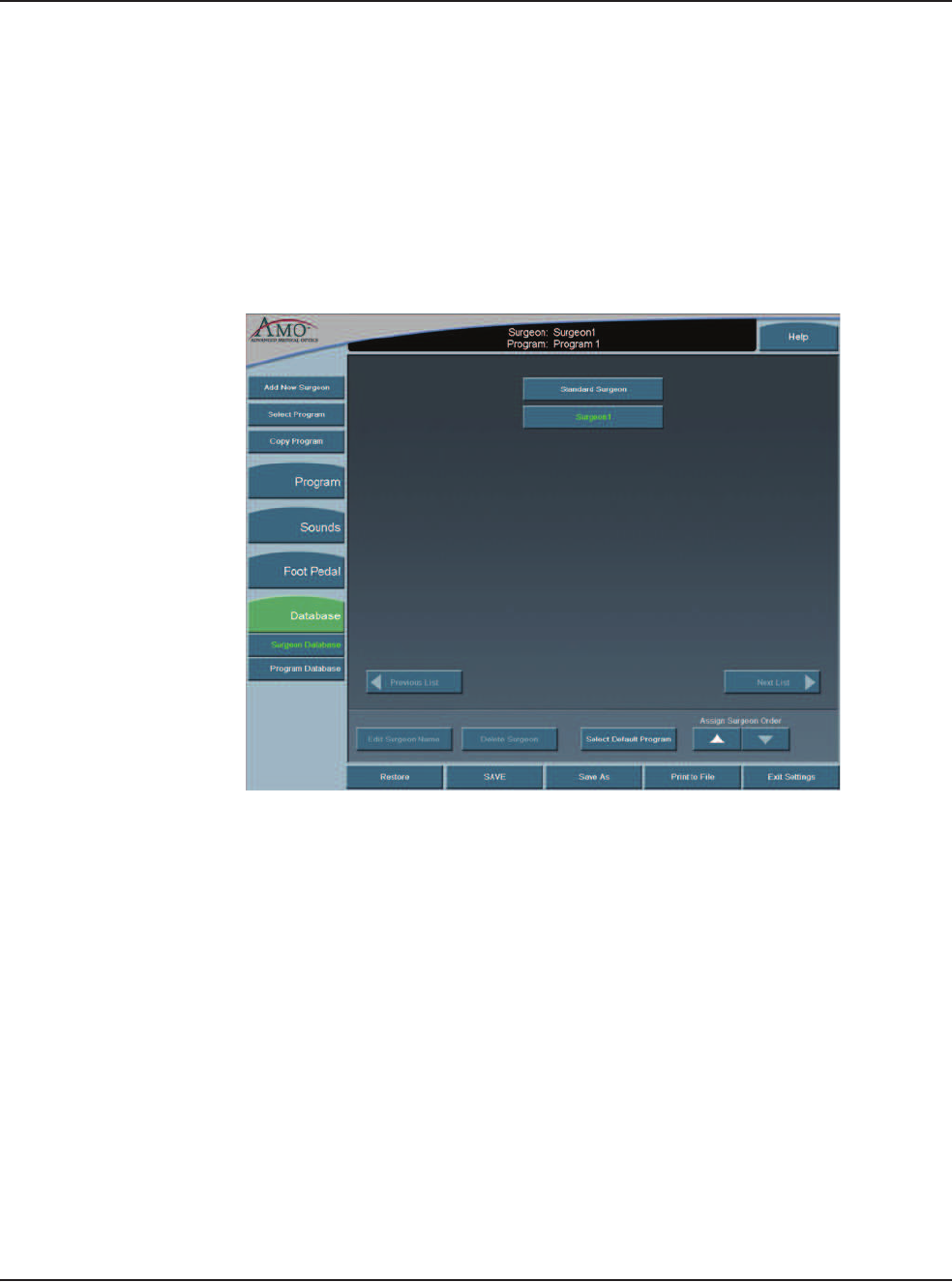
Edit a Surgeon 1. Press Configuration.
2. Press Surgeons and Programs.
3. Press Database.
4. Press Surgeon Database button.
5. Select a surgeon from the list.
Figure 6.5 – Select Surgeon
6. Press Edit Surgeon Name. The Keyboard window appears.
7. Edit the name.
8. Press Enter.
9. Press Exit Settings.
6 • Surgeon Programs
WHITESTAR SIGNATURE™ System Rx Only – Z370147 Rev. C 1008 6-6
Select a Preferred
Program
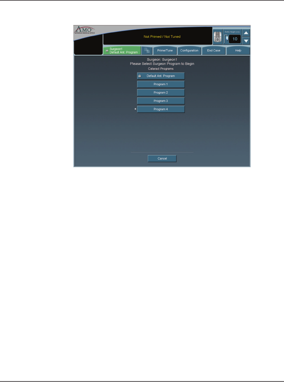
Use the Select Surgeon screen to assign your preferred or default program. the
program selected here is indicated with an asterisk (*) on the Select Program to
Begin screen when the system is started. When you select Next Case the system
asks if you want to return to your preferred program. You are prompted only if you
are not in your preferred program.
1. Press Configuration.
2. Press Surgeons and Programs.
3. Press Database.
4. Press Surgeon Database.
5. Select a surgeon from the list.
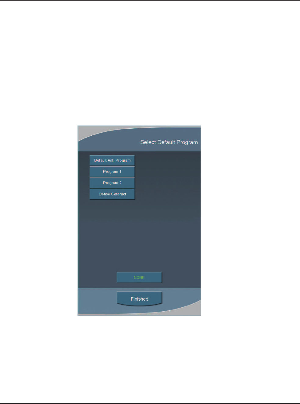
6. Select Assign Default Program.
Figure 6.6 – Select Default Program Pop-up
7. Select a program or select None to clear a selection.
8. Select Finished to close the window. Your preferred program is indicated with
an asterisk on the Select Program to Begin screen when the system is started.
6 • Surgeon Programs
WHITESTAR SIGNATURE™ System Rx Only – Z370147 Rev. C 1008 6-7
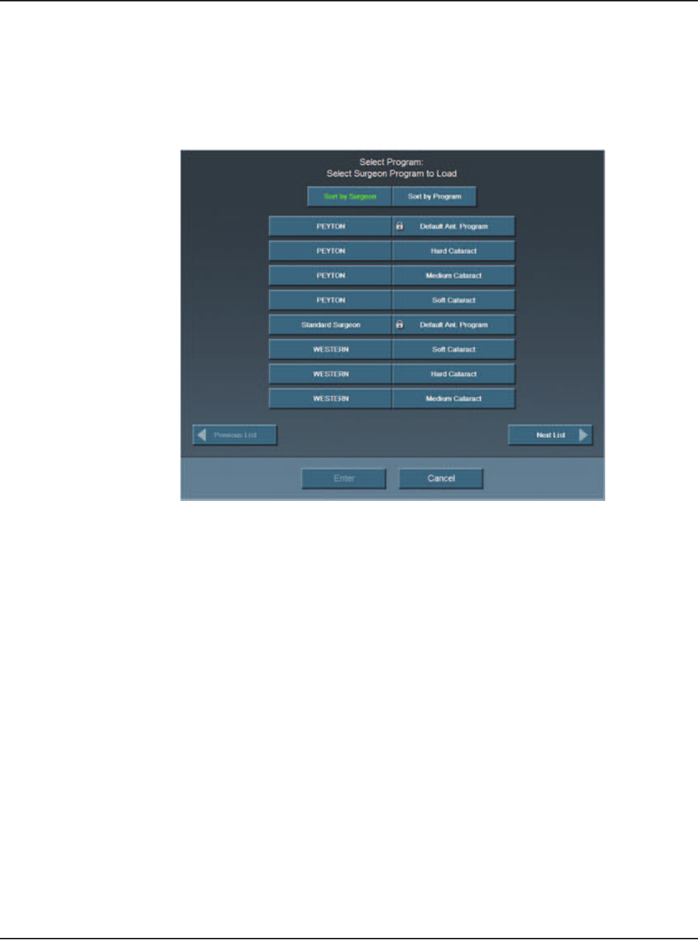
Figure 6.7 – Select a Program to Begin Screen

6 • Surgeon Programs
WHITESTAR SIGNATURE™ System Rx Only – Z370147 Rev. C 1008 6-8
Create a New
Program
When you create a new surgeon, that surgeon is assigned the AMO Default
Program setup. You can customize a program for that surgeon name with your
preferred settings. You can also create new programs for existing surgeons.
1. Press Configuration.
2. Press Surgeons and Programs.
3. Press Select Program.
4. Select the surgeon or program from the list.
5. Press Enter.
6. Edit the settings for this program on the Settings window. Use the Copy
Program to copy another surgeon's program. Refer to Copy a Surgeon
Program in this chapter.
7. Press Save As. The Keyboard window opens.
8. Enter the name of the program.
9. Press Enter.
10. Press Exit Settings.
6 • Surgeon Programs
WHITESTAR SIGNATURE™ System Rx Only – Z370147 Rev. C 1008 6-9
Edit a Surgeon
Program
1. Press Configuration.
2. Press Surgeons and Programs.
3. Press Select Program.
4. Select the surgeon or program from the list.
Figure 6.8 – Select Program
5. Press Enter.
6. Select the mode and submode to edit.
7. Edit the settings for this program on the Settings window.
8. Press SAVE.
9. Press Exit Settings.

6 • Surgeon Programs
WHITESTAR SIGNATURE™ System Rx Only – Z370147 Rev. C 1008 6-10
Copy a Surgeon
Program
You can copy the settings of one surgeon program for use by another surgeon.
To copy a surgeon program:
1. Press Configuration.
2. Select Surgeons and Programs.
3. Press Copy Program and select the Surgeon or Program you want to copy
from the list. This copies all of the settings of the selected program and the
submodes.
Note: If Standard Surgeon is the active surgeon, Copy Program is not
available to the user. Press Select Program to change the surgeon and
program.
4. Press Enter.
5. Press Save As at the bottom of the screen. The Keyboard window opens.
6. Enter the new name for the program.
7. Press Enter to save the new program and exit the Keyboard window. The new
program now appears in the list of available programs.
8. Press Exit Settings.
6 • Surgeon Programs
WHITESTAR SIGNATURE™ System Rx Only – Z370147 Rev. C 1008 6-11
Delete a Surgeon Use Delete Surgeon to remove a surgeon from the Select Surgeon screen. You
cannot delete the current surgeon.
Note: You cannot delete a current surgeon or a surgeon that is selected on the
Settings screen.
1. Press Configuration.
2. Press Surgeons and Programs.
3. Press Database.
4. Press Surgeon Database.
5. Select a surgeon to delete.
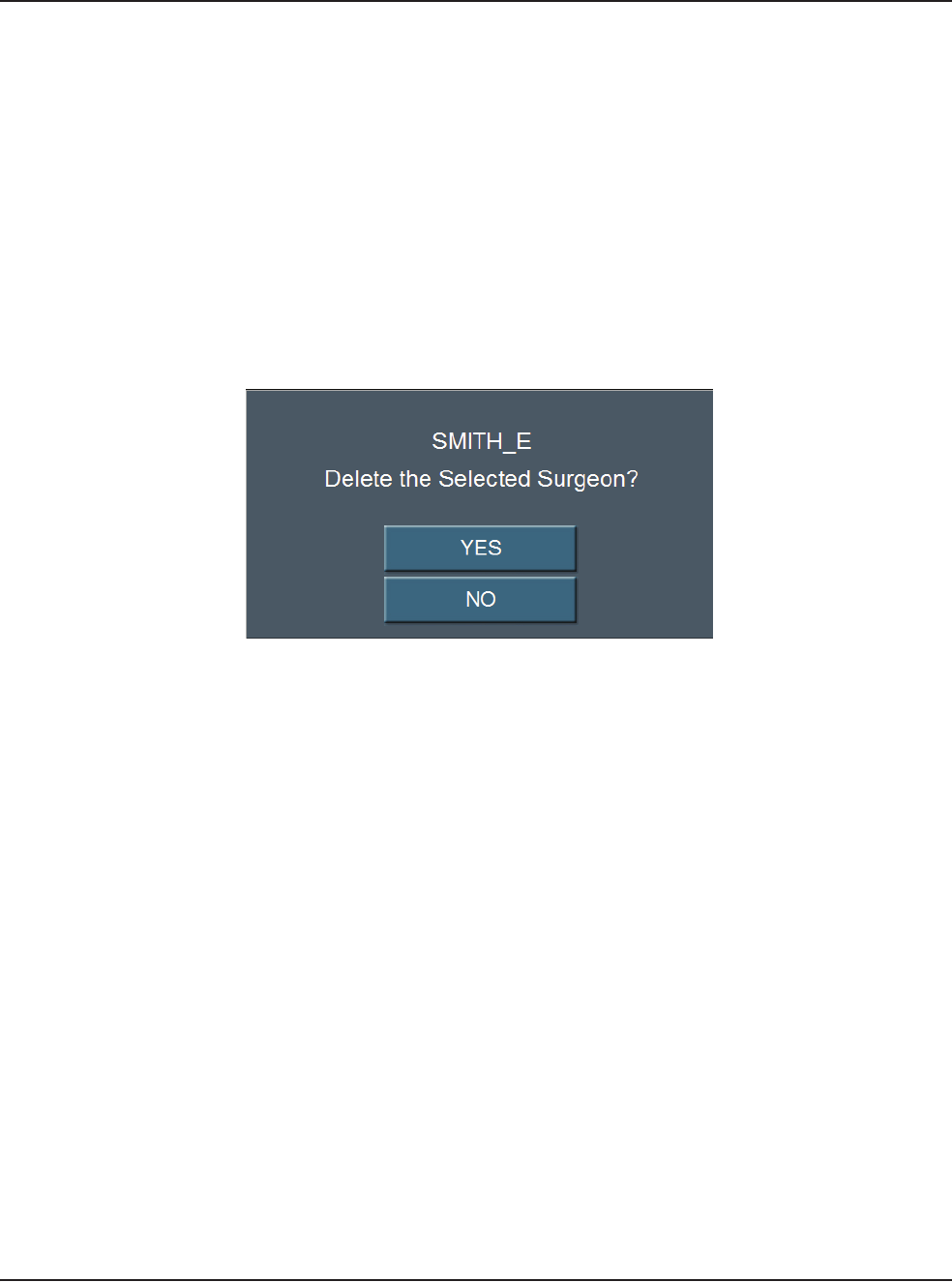
6. Select Delete Surgeon. A delete confirmation pop-up appears.
Figure 6.9 – Delete Confirmation Pop-up Window
7. Press Yes.
8. Select Exit Settings.
6 • Surgeon Programs
WHITESTAR SIGNATURE™ System Rx Only – Z370147 Rev. C 1008 6-12
Delete a Program Use Delete Program to remove a surgeon program from the Select Program
screen. You cannot delete the current program.
Note: You cannot delete a current program or a program that is selected on the
Settings screen.
1. Press Configuration.
2. Press Surgeons and Programs.
3. Press Database.
4. Press Program Database.
5. Select a program to delete.
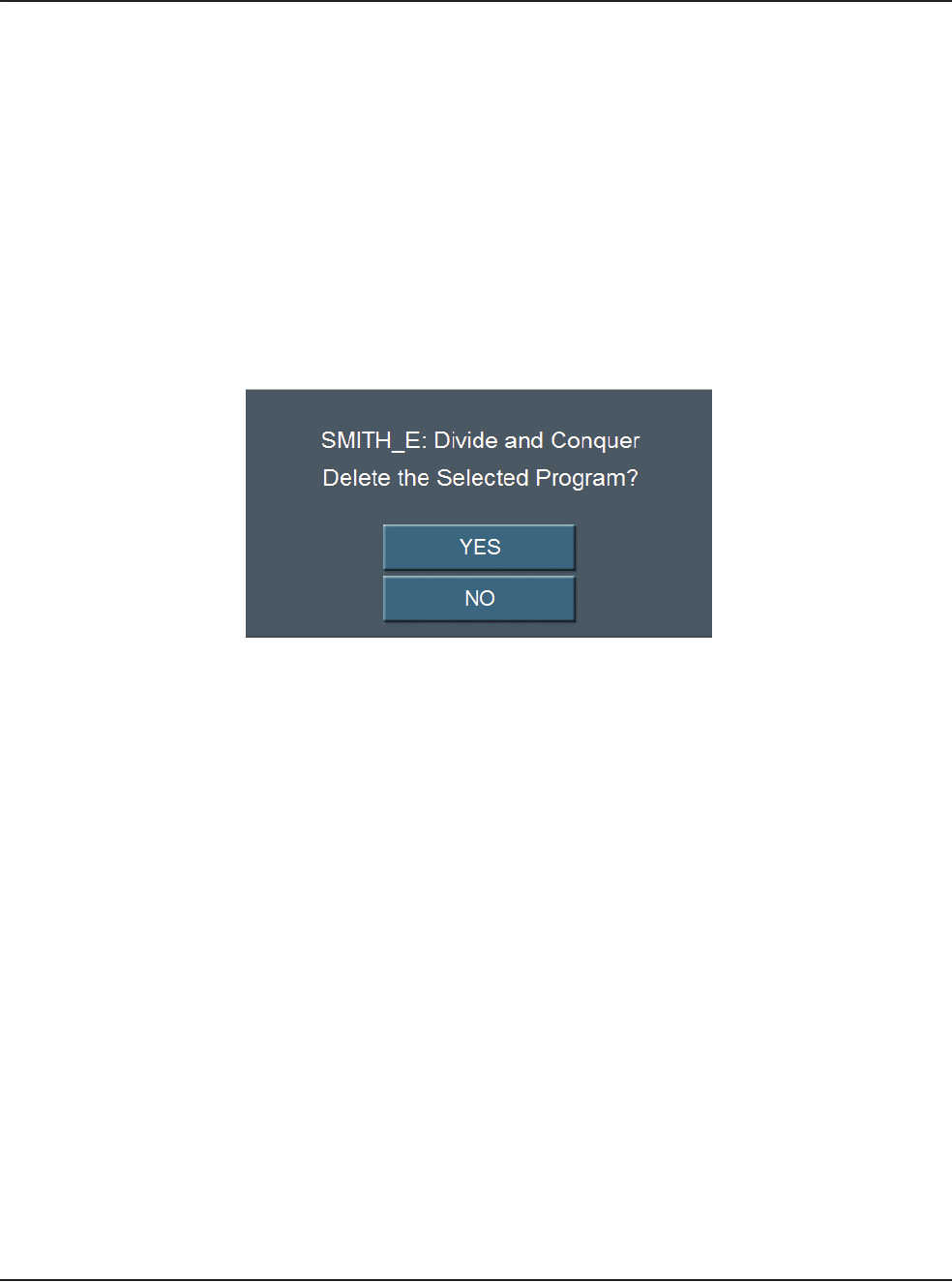
6. Select Delete Program. A delete confirmation pop-up appears.
Figure 6.10 – Deletion Confirmation
7. Press Yes.
8. Select Exit Settings.
6 • Surgeon Programs
WHITESTAR SIGNATURE™ System Rx Only – Z370147 Rev. C 1008 6-13
Delete a Database You can delete a database from your memory device. Contact your AMO Service
Representative to delete a database from your system's hard drive.
Note: Use only AMO recommended USB stick drives.
1. Insert the USB flash drive into the port on the back of the system.
2. From Configuration, press System Configuration to access the Diagnostic
screen.
3. Press Restore All.
4. Press the database to delete from the list.
5. Press Delete Selection.
6. Press OK at the confirmation window.
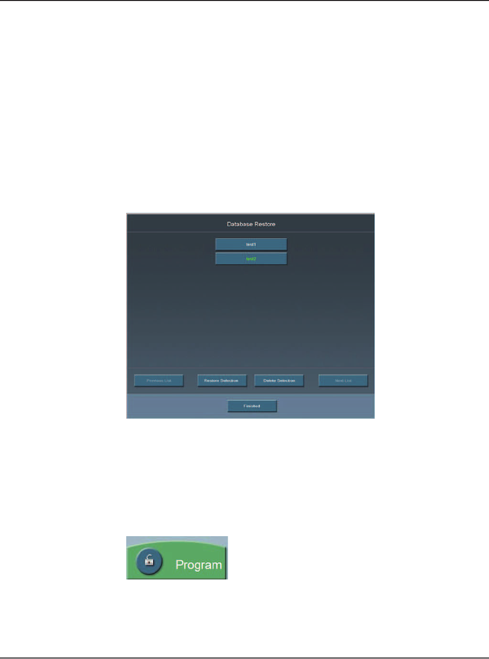
7. Press Finished to close the window.
Figure 6.11 – Database Restore Screen
Lock a Program Press the open padlock at any time to lock the program. To edit a locked program,
use Save As and rename the program.
Note: When a program is locked the program cannot be unlocked. You cannot
edit a locked program.
Figure 6.12 – Program Lock Button
6 • Surgeon Programs
WHITESTAR SIGNATURE™ System Rx Only – Z370147 Rev. C 1008 6-14
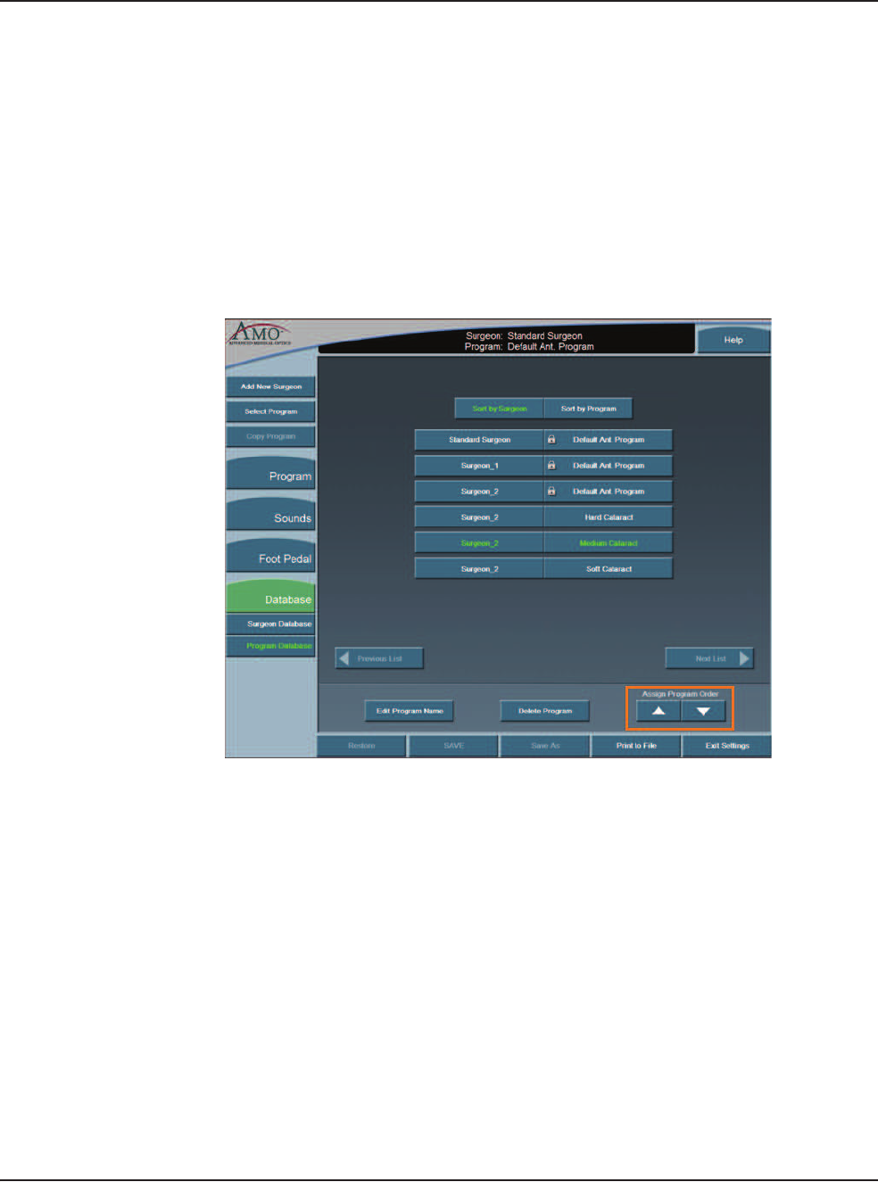
Program – Assign
Order
Use Program Assign Order to change the order in which the surgeon names are
shown on the Select Surgeon window.
1. Press Configuration.
2. Press Surgeons and Programs.
3. Press Database.
4. Select Program Database. A list of programs appears.
5. Select a program.
6. Use the Assign Program Order Up and Down arrows to move the Program.
The arrows are found at the bottom of the window.
Figure 6.13 – Surgeon and Program Databases
7. Repeat steps 5 and 6 until you are satisfied with the order.
8. Select Exit Settings.

WHITESTAR SIGNATURE™ System Rx Only – Z370147 Rev. C 1008 7-1
Diagnostics
Wireless Footpedal Setup
Wireless Foot Pedal Calibration
Wireless Remote Control Setup
Calibrate Touch Screen
7DIAGNOSTICS
7 • Diagnostics
WHITESTAR SIGNATURE™ System Rx Only – Z370147 Rev. C 1008 7-2
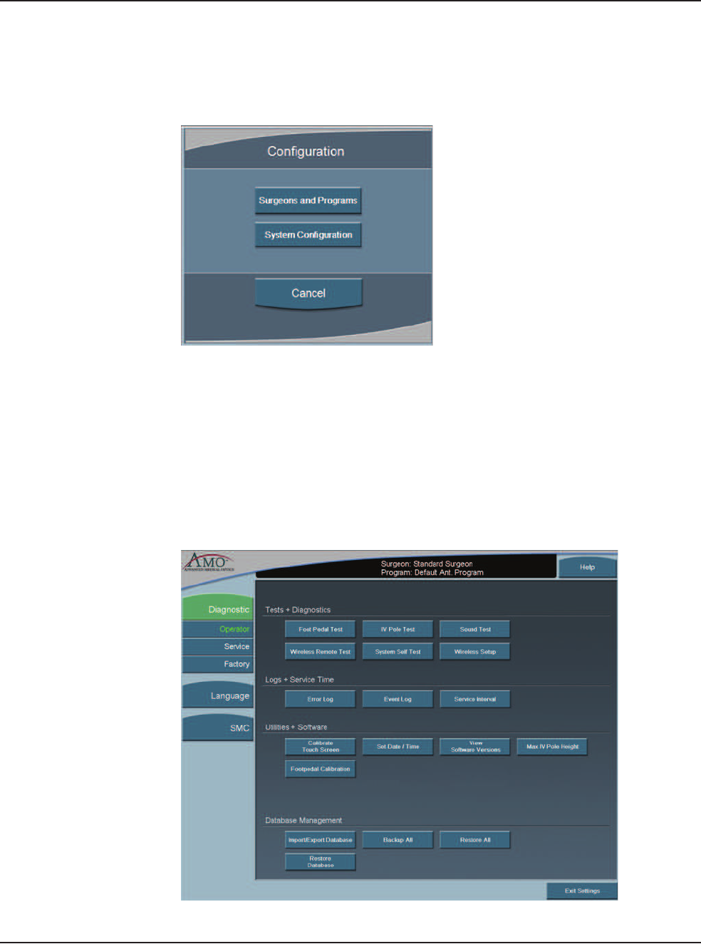
Diagnostics To access diagnostics:
1. Press Configuration.
Figure 7.1 – Configuration Pop-up Window
2. Press System Configuration. On the System Configuration screen, Diagnostic
is selected by default.
The Diagnostic screen shows the various Diagnostic Routines, Logs, System
Utilities and Database Management functions that can be accessed by the Operator.
Press the button for the diagnostic routine you want to run or view. Follow the
instructions on the screen to complete the test process. The Service and Factory
Diagnostic routines can only be accessed by authorized AMO service personnel.
Figure 7.2 – Diagnostics Screen
7 • Diagnostics
WHITESTAR SIGNATURE™ System Rx Only – Z370147 Rev. C 1008 7-3
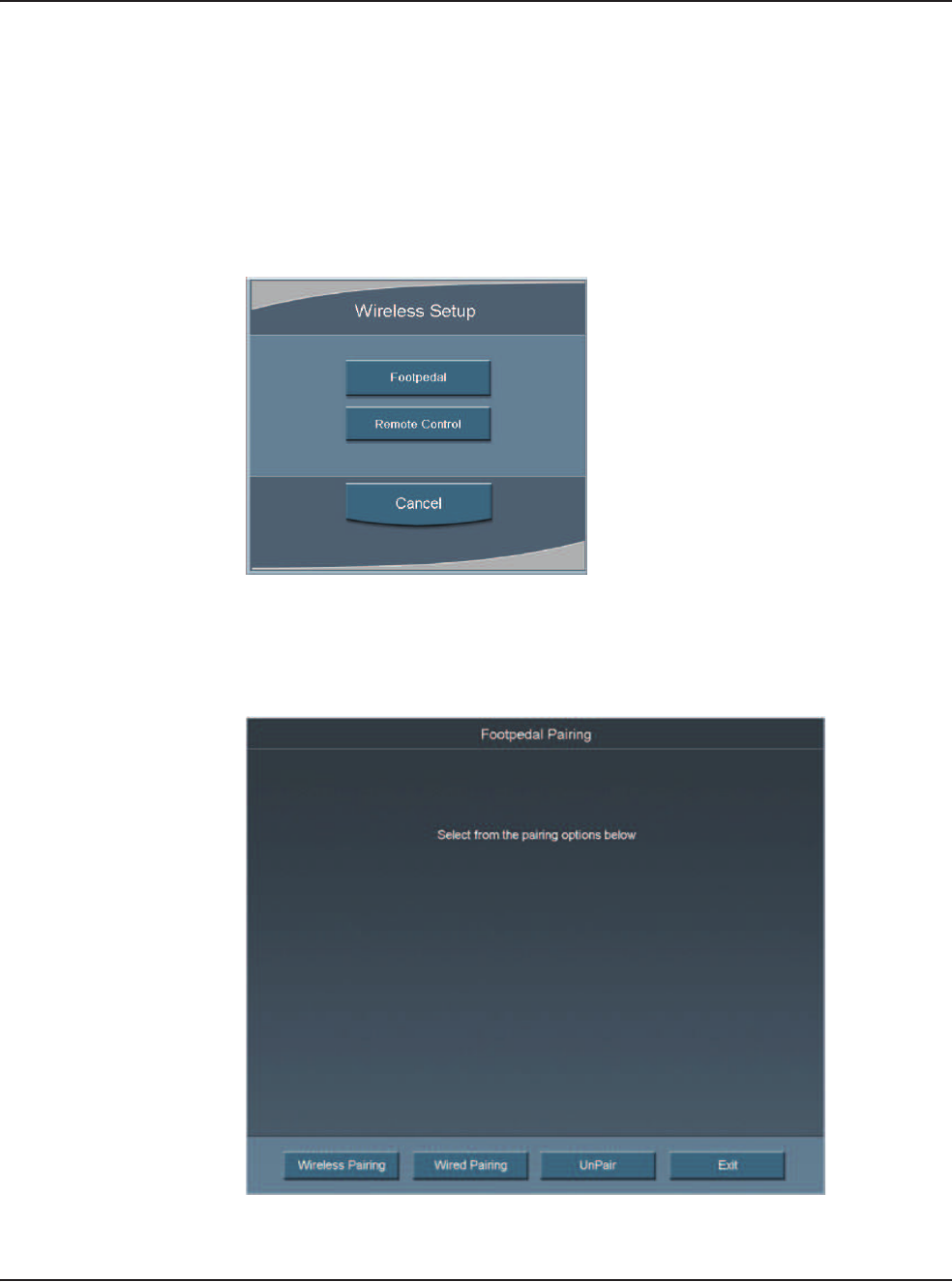
Wireless Footpedal
Setup
You can pair the Wireless Foot Pedal (Advanced Control Pedal) to the system with
either the Footpedal Cable or wireless. The Wireless Foot Pedal uses Bluetooth®
technology to communicate with the system. The Wireless Foot Pedal has a range
of ten (10) feet from the system.
1. Press Wireless Setup.
2. Select Footpedal.
Figure 7.3 – Wireless Setup Pop-up Screen
3. Select either Wireless Pairing or Wired Pairing. To use Wired Pairing you
must have the Footpedal Cable attached to the system.
Figure 7.4 – Footpedal Pairing Screen
4. Follow the instructions shown on the screen.

7 • Diagnostics
WHITESTAR SIGNATURE™ System Rx Only – Z370147 Rev. C 1008 7-4
Figure 7.5 – Wireless Footpedal Pairing Instructions
5. Press Exit to close the screen and access the Foot Pedal Test screen.
• If the blue light is on, the wireless foot pedal is paired.
• If the blue light is flashing the wireless foot pedal is not paired.
• If the green light is on, the batteries in the foot pedal are charged.
• If the green light is blinking, the batteries in the wireless foot pedal need to
be charged. Attach the cable to charge the batteries.
6. Use UnPair to unpair either of the Advanced Control Pedals (dual linear) from
the system.
7 • Diagnostics
WHITESTAR SIGNATURE™ System Rx Only – Z370147 Rev. C 1008 7-5
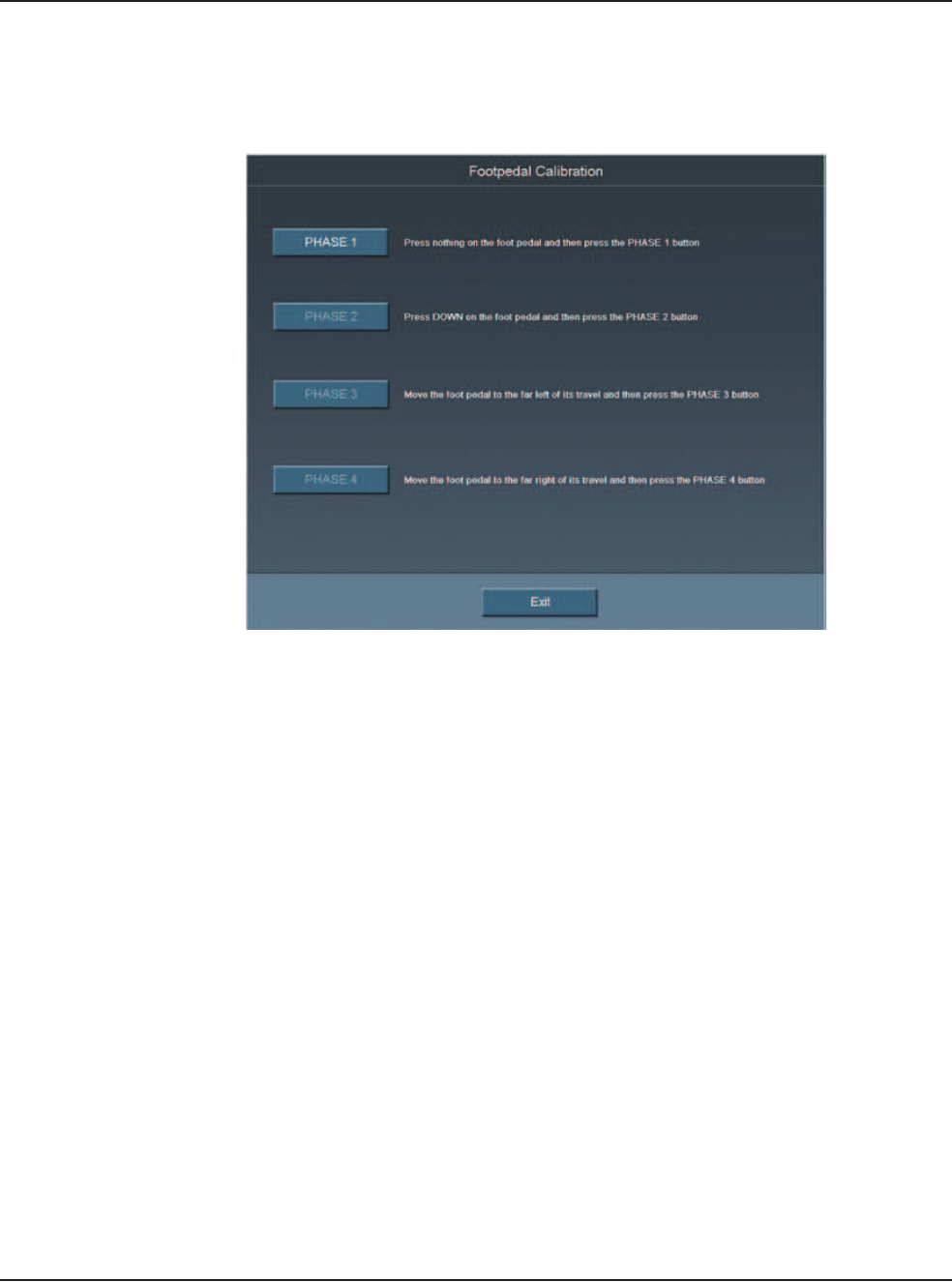
Wireless Foot Pedal
Calibration
To maintain optimal use of the foot pedal, the wireless foot pedal must be
calibrated from time to time.
Figure 7.6 – Footpedal Calibration Screen
1. Press Footpedal Calibration from the Diagnostic screen. The Footpedal
Calibration screen can also be accessed from the Foot Pedal Threshold screen.
Note: Only press the foot pedal when you are instructed. If you press the foot
pedal at any other time the calibration of the foot pedal can fail.
2. Follow the instructions shown on the screen. The Calibration screen closes
automatically when completed and the Foot Pedal Test screen opens.
3. Test the foot pedal.
7 • Diagnostics
WHITESTAR SIGNATURE™ System Rx Only – Z370147 Rev. C 1008 7-6
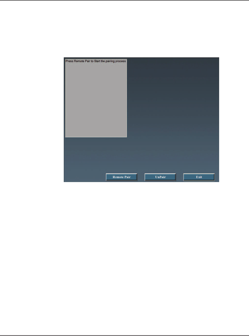
Wireless Remote
Control Setup
Use the Wireless Setup button to connect the System with a Wireless Remote
Control.
Note: Make sure that the Backlight feature for the Wireless Remote Control is off
(before you start the Wireless Setup process).
Figure 7.7 – Wireless Setup Screen
1. Press Wireless Setup.
2. Select Remote Control.
3. Press Remote Pair.
4. Follow the messages shown on the screen.
5. For the Remote Control:
• Press the corresponding buttons on the wireless remote control as prompted.
If Remote Pair fails, follow the instructions on the screen.
• Press the buttons on the wireless remote control.
• Verify for each button that the corresponding button on the screen lights. If
the button does not light on the screen, the test fails. If the test fails contact
AMO for technical service.
6. Press Exit to close the window.
7. Press the Unpair button to unpair the Remote.

7 • Diagnostics
WHITESTAR SIGNATURE™ System Rx Only – Z370147 Rev. C 1008 7-7
Calibrate Touch
Screen
The System touch screen needs to be calibrated as part of the system maintenance.
Press Calibrate Touch Screen to start the calibration procedure.
1. Press the center of the target circle until the Touch message changes to
Release.
Figure 7.8 – Touch Screen Target Circle
2. When released, the circle moves to the next point to be calibrated.
3. Repeat Step 1 for all of the calibration points.
4. Press Accept when all of the calibration points are completed.

WHITESTAR SIGNATURE™ System Rx Only – Z370147 Rev. C 1008 8-1
System Check-out
8CHECK-OUT PRECAUTIONS

8 • Check-out Precautions
WHITESTAR SIGNATURE™ System Rx Only – Z370147 Rev. C 1008 8-2
System Check-out The purpose of the check-out procedure is to verify that the System is installed and
operating properly. The check-out procedure must be performed at least prior to the
first case of the day and any time program changes are made as outlined in the
following steps. The IA mode and handpiece are tested first, then the PHACO
mode and handpiece, so that the phaco handpiece (which is used first) is set up and
ready for surgery.
If any of the check-out steps are not successfully performed, they must be repeated.
If the instrument still does not work correctly, refer to Chapter 10, “Error Messages
Troubleshooting and Diagnostics”.
Note: Refer to WARNINGS in Chapter 3, “System Setup” before you set up the
System.
Set-Up and Prime/Tune
Refer to the System Setup and Equipment Operation chapters of this manual for
instructions on installing the tubing and priming/tuning the system.
Irrigation and Aspiration
1. Connect the tubing to the IA handpiece.
2. Select IA mode.
3. Hold the test chamber near the handpiece tip, press and hold the footpedal in
Position 1.
4. Observe the irrigation flow.
Phacoemulsification
1. Connect the tubing to the phaco handpiece.
2. Screw the phaco needle onto the handpiece, use your fingers to engage the
screw thread, and then use the tip wrench to tighten the needle. Screw the
irrigation sleeve assembly over the needle.
3. Select the PHACO mode.
4. Press and hold the footpedal in Position 1.
5. Observe the irrigation flow.
6. Hold the handpiece approximately at the patient’s eye level, and fill the test
chamber with irrigation fluid.
7. Place the test chamber over the irrigation sleeve.
8. Occlude the aspiration tubing just below the phaco handpiece. Press and hold
the footpedal in Position 2. The actual vacuum level should rise to the preset
level.

8 • Check-out Precautions
WHITESTAR SIGNATURE™ System Rx Only – Z370147 Rev. C 1008 8-3
9. Release the occlusion and watch the test chamber to make sure that the test
chamber does not collapse. A dent or dimple in the test chamber is normal.
10. To test irrigation, pinch the irrigation tubing at the IA handpiece and watch for
the test chamber to collapse. Release the irrigation tubing and the test chamber
should fill.
11. Press Next Case to reset the Phaco timer.
Phacoemulsification check-out is complete.
Diathermy
CAUTION: IF A TONE IS NOT HEARD WHEN THE
FOOTPEDAL IS PRESSED AND VOLUME ADJUSTMENT IS
UNSUCCESSFUL, THE MODE IS NOT FUNCTIONING PROPERLY.
REFER TO Chapter 10, “Error Messages Troubleshooting and Diagnostics”.
1. Connect the Diathermy forceps to the cable and the cable to the front panel of
the console.
2. Select the Diathermy mode.
3. Press the footpedal. A tone should be heard when the footpedal is pressed.
Vitrectomy
1. Attach the irrigation and aspiration cassette pack tubing together.
2. Press Prime on the Prime/Tune screen.
3. Press the VIT button to enter VIT mode.
4. Follow the instructions on the screen.
5. Observe that the:
• irrigation fluid flows
• aspiration tubing is full and clear of air
• the vitrectomy cutter motor is activated (slight sense of motion of the
handpiece)
• cutter blade operates
6. Press Start Vit Prime. The screen closes automatically when the handpiece is
primed.
Vitrectomy check-out is complete.
!

WHITESTAR SIGNATURE™ System Rx Only – Z370147 Rev. C 1008 9-1
Cleaning Procedures
Sterilization Procedures
WHITESTAR SIGNATURE™ System Cleaning and Care
9CARE AND CLEANING

9 • Care and Cleaning
WHITESTAR SIGNATURE™ System Rx Only – Z370147 Rev. C 1008 9-2
Cleaning Procedures All previously used reusable items must be handled according to ANSI/AAMI
ST79:2006 Comprehensive guide to steam sterilization and sterility assurance in
health care facilities. Information about the reuse of any products can be found in
the Directions for Use for the particular product. All single use items or items
which have completed their recommended useful life must be disposed of in
accordance with accepted hospital practices and procedures and local governing
ordinances and recycling plans. These items can include, but are not limited to,
waste materials, waste collection bags, tubing, infusion-sleeves and test chambers.
Note: Inspect the Diathermy, Vitrectomy and Phaco handpiece cables for possible
damage on a daily basis.
Phaco Handpiece
The following cleaning procedures for the phaco handpieces must be implemented
immediately after use. The straight-through design of the phaco handpiece makes
cleaning easy and greatly reduces the likelihood of the handpiece clogging.
However, to maximize the life of your instruments, you must clean the instruments
immediately after use. Failure to properly clean the instrument can result in tissue
buildup and dangerous cross-contamination.
WARNING: Balanced salt solutions tarnish and pit metals, which causes
the handpiece to deteriorate. Proper cleaning of the instruments prolongs their
useful life. AMO recommends using sterile nonpyrogenic water to clean the
handpieces and accessories.
CAUTION: DO NOT STERILIZE THE HANDPIECES PRIOR TO
PERFORMING THE CLEANING PROCEDURES DESCRIBED BELOW.
The following cleaning procedure is to be performed at the end of each surgical
case:
1. With the tip cap sleeve and phaco tip still in place on the handpiece, inject 60 cc
of sterile nonpyrogenic water through the irrigation tubing of the handpiece
with a syringe. Remove the syringe and fill the syringe with air. Attach the
syringe and flush the tube and handpiece with air.
2. Inject 60 cc of sterile nonpyrogenic water through the aspiration tubing of the
phaco handpiece. It is helpful to use a female to female connector to attach the
syringe to the aspiration tubing. Remove the syringe and fill the syringe with
air. Attach the syringe and flush the tube and handpiece with air.
3. Carefully remove the phaco tip cap sleeve and phaco tip from the handpiece for
disposal or to be sanitized and stored
4. Inject sterile nonpyrogenic water into the test chamber with a syringe and then
empty. Repeat this step three to four times.
!
!
9 • Care and Cleaning
WHITESTAR SIGNATURE™ System Rx Only – Z370147 Rev. C 1008 9-3
5. Aspirate sterile nonpyrogenic water through the phaco tip into a syringe; this
clears any debris from within the tip and prevents clogging of the suction port.
6. Gently wipe the power cable of the handpiece with gauze soaked in distilled
water.
WARNING: Improper/inadequate cleaning may result in particulate
matter adhering to the instrument and exfoliation of particles into the surgical field.
In addition, the function and life expectancy of the phaco handpiece can become
compromised.
CAUTION: DO NOT CLEAN THE PHACO HANDPIECE WITH
ANY TYPE OF ULTRASONIC CLEANING DEVICE; THE CLEANING
DEVICE CAN DAMAGE THE PIEZOELECTRIC CRYSTALS.
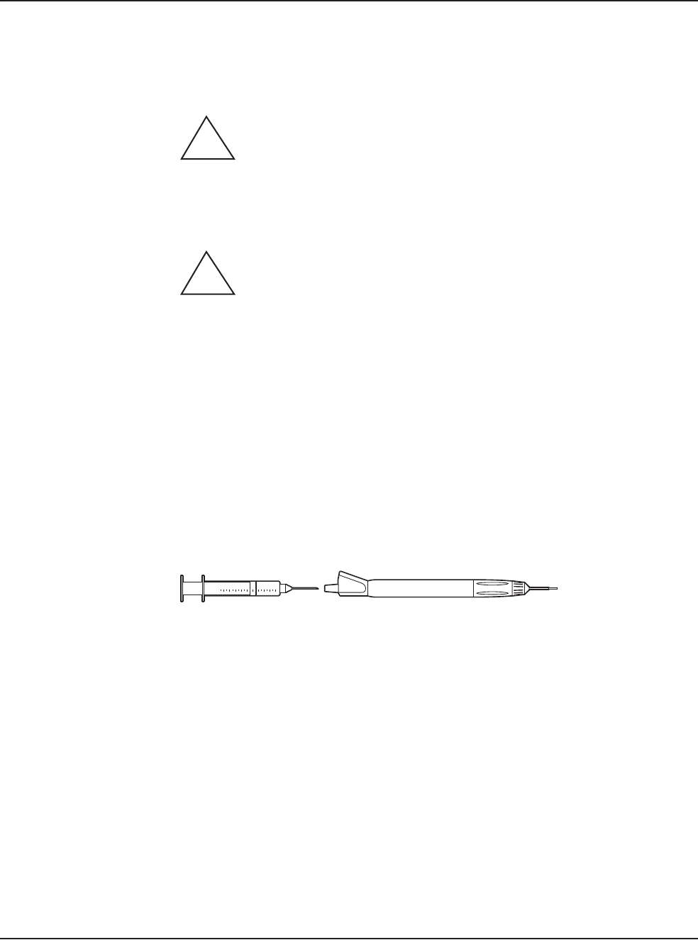
Irrigation/Aspiration Handpiece
1. Back-flush the IA handpieces immediately at the end of the procedure.
Use a 10cc syringe with sterile nonpyrogenic water and flush the water from
the back of the handpiece through the tip. This process must be performed at
least two times through both the irrigation and aspiration channels.
Note: You can use other available AMO™ products designed for this process
(IA Cleaning Kit, AMO Part No. OM05510114).
Figure 9.1 – I/A Handpiece Cleaning
2. Make sure IA handpieces are dry when they are stored.
Diathermy Handpiece
Clean the diathermy handpieces with the same procedures you use to clean other
ophthalmic instruments.
Note: Inspect the Diathermy, Vitrectomy and Phaco handpiece cables for possible
damage on a daily basis.
Vitrectomy Cutter
The vitrectomy cutter is a disposable, single-use instrument.
!
!

9 • Care and Cleaning
WHITESTAR SIGNATURE™ System Rx Only – Z370147 Rev. C 1008 9-4
Sterilization
Procedures
AMO recommends that you follow the sterilization procedures outlined in this
section to maximize the life of your System instruments.
All parts must be cleaned thoroughly prior to sterilization, and all sterilization
equipment must be validated prior to use.
CAUTION: DO NOT STERILIZE THE HANDPIECES PRIOR TO
PERFORMING THE CLEANING PROCEDURES DESCRIBED EARLIER
IN THIS SECTION.
THE STORAGE CASES PROVIDED CANNOT BE PLACED IN AN
AUTOCLAVE.
The following sterilization techniques, times, and temperatures must be used in
order to ensure consistent product performance:
Gravity Displacement Sterilization – A type of sterilizer in which incoming steam
displaces the residual air through a port or drain usually in or near the bottom of the
sterilizer chamber. Typical operating temperatures are 121 to 123°C (250 to 254°F)
and 132 to 135°C (270 to 275°F).
Prevacuum Sterilization – A type of sterilizer which relies on one or more pressure
and vacuum excursions at the beginning or end of the cycle.
This method of operation usually results in shorter cycle times because of the rapid
removal of air from the chamber and the load by the vacuum system, the usually
higher operating temperature (132 to 135°C / 270 to 275°F; 141 to 144°C / 285 to
290°F), and the shorter exposure time for porous loads.
Note: The cycle times require the product to be wrapped. In an emergency
situation only Flash Sterilization in accordance with ANSI/AAMI
ST79:2006 Comprehensive guide to steam sterilization and sterility
assurance in health care facilities can be used. The parameters for mixed
porous and nonporous items must be used.
CAUTION: GAS STERILIZATION IS NOT RECOMMENDED.
Cooling is not necessary prior to reassembly; however, caution must be used to
prevent burns. Follow the handpiece assembly instructions.
!
!

9 • Care and Cleaning
WHITESTAR SIGNATURE™ System Rx Only – Z370147 Rev. C 1008 9-5
WARNING: Sterility assurance is the responsibility of the user. All non-
sterile accessories must be sterilized prior to use. In addition, AMO recommends a
terminal sterilization cycle in the autoclave after the final case of the day. This
cycle must include a drying cycle to remove moisture from the tubing and
handpieces for storage.
Devices undergoing sterilization must be thoroughly cleaned to minimize
bio-burden. Validation of the sterilization vessel and the sterilization cycle is the
responsibility of the user.
1. After sterilization, store the instruments in a safe, clean environment. Keep the
instruments dry and free of dust. Make sure that the handpiece nose cone tips
are adequately protected during storage.
2. Do not wind the phaco handpiece cord too tight. Handle the cord as you would
a fiber optic cable. Follow the natural curve of the cord and wind only as tight
as the natural curve of the cord (approximately 6 inch coiled cord diameter).
WARNING: Handle the phaco handpiece with extreme care. The
piezoelectric crystal in the handpiece is very sensitive to shock. If the handpiece is
dropped, it is possible that the handpiece might not function correctly. If this
happens, contact AMO for repair information or replacement.
WHITESTAR
SIGNATURE™
System Cleaning and
Care
1. Turn the power switch on the back of the System Off before you unplug the
system from the wall outlet.
2. At the end of the day, thoroughly wipe down the system, cart, power pole and
footpedal using a cloth dampened with a germicidal detergent and sterile
nonpyrogenic water. Be careful not to saturate any part of the system or the
footpedal with liquid. Excessive liquid can damage the System electronics.
3. Do not push or pull on the system components.
4. AMO recommends that you leave the footpedal and power cords connected to
the system to prevent loss and unnecessary wear on the electrical connectors.
5. Although the footpedal is water-resistant, make sure that the footpedal is kept
as dry as possible.
6. Place the Advanced Control Pedal (dual linear) in the storage recess at the
bottom of the console so that the footpedal batteries can charge. You can attach
the footpedal cable to the console to charge the batteries.
7. Place the wireless remote control in the storage recess on the top of the console
so that the Wireless Remote Control batteries can charge.
!
!

WHITESTAR SIGNATURE™ System Rx Only – Z370147 Rev. C 1008 10-1
Error Message Display
Fuse Replacement Procedure
Wireless Foot Pedal Battery Replacement Procedure
Most Common User-Correctable Problems
Status, Warning and Error Messages
System Operation (Error) Messages
Troubleshooting
10 ERROR MESSAGES
TROUBLESHOOTING AND
DIAGNOSTICS

10 • Error Messages Troubleshooting and Diagnostics
WHITESTAR SIGNATURE™ System Rx Only – Z370147 Rev. C 1008 10-2
Error Message
Display
The red Error Messages are shown at the top of the screen. Press the Help button to
open the corrective action for that error. When the error is corrected, press OK to
clear the error message from the screen. If the error message is cleared but not
corrected, the error message is generated again.
The yellow Alerts are shown at the top of the screen. The alert does not need to be
cleared as an error message. An alert, for example, can be: Remote Control Battery
power level is 10 – 25% of maximum. The battery needs to be charged.
WARNING: DO NOT try to replace the Wireless Remote Control
batteries. Call your AMO Technical Service representative to replace the batteries.
Fuse Replacement
Procedure
If the System does not turn on when the power switch is turned On, and you have
confirmed that the power cord is properly connected and plugged in, check to see if
the fuse is bad.
Note: To prevent the risk of fire or damage to the instrument, replace the fuses
with the exact type and rating as indicated below (check the voltage sticker
on the back panel of System to confirm your system voltage):
Table 10.1 – Fuse Specifications
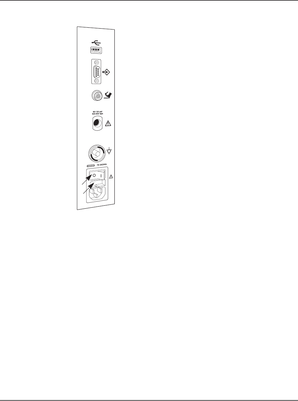
To replace the console fuses:
1. Unplug the System electrical power.
2. Unplug the power cord from the back panel.
3. Locate the fuse holder on the back panel of the System, as shown below.
4. Use a small screwdriver to gently pry open the cover and expose the fuse
holder.
5. Gently pry out the fuse holder.
6. Remove the bad fuse and replace the fuse with a new fuse (value and size
specified above).
7. Replace the fuse holder. Make sure that the arrows point to the right side of the
back panel. Tilt the fuse holder slightly to the right and push in.
8. Push the fuse holder cover up and in until the cover snaps closed.
9. Reconnect the power cord to the back panel.
10. Plug the System into an electrical receptacle (outlet).
!
Voltage Quantity Fuse
Specifications
Console 100/120/240 2 6.3A, 250V,
Bussman GDA
10 • Error Messages Troubleshooting and Diagnostics
WHITESTAR SIGNATURE™ System Rx Only – Z370147 Rev. C 1008 10-3
Figure 10.1 – Fuse Location
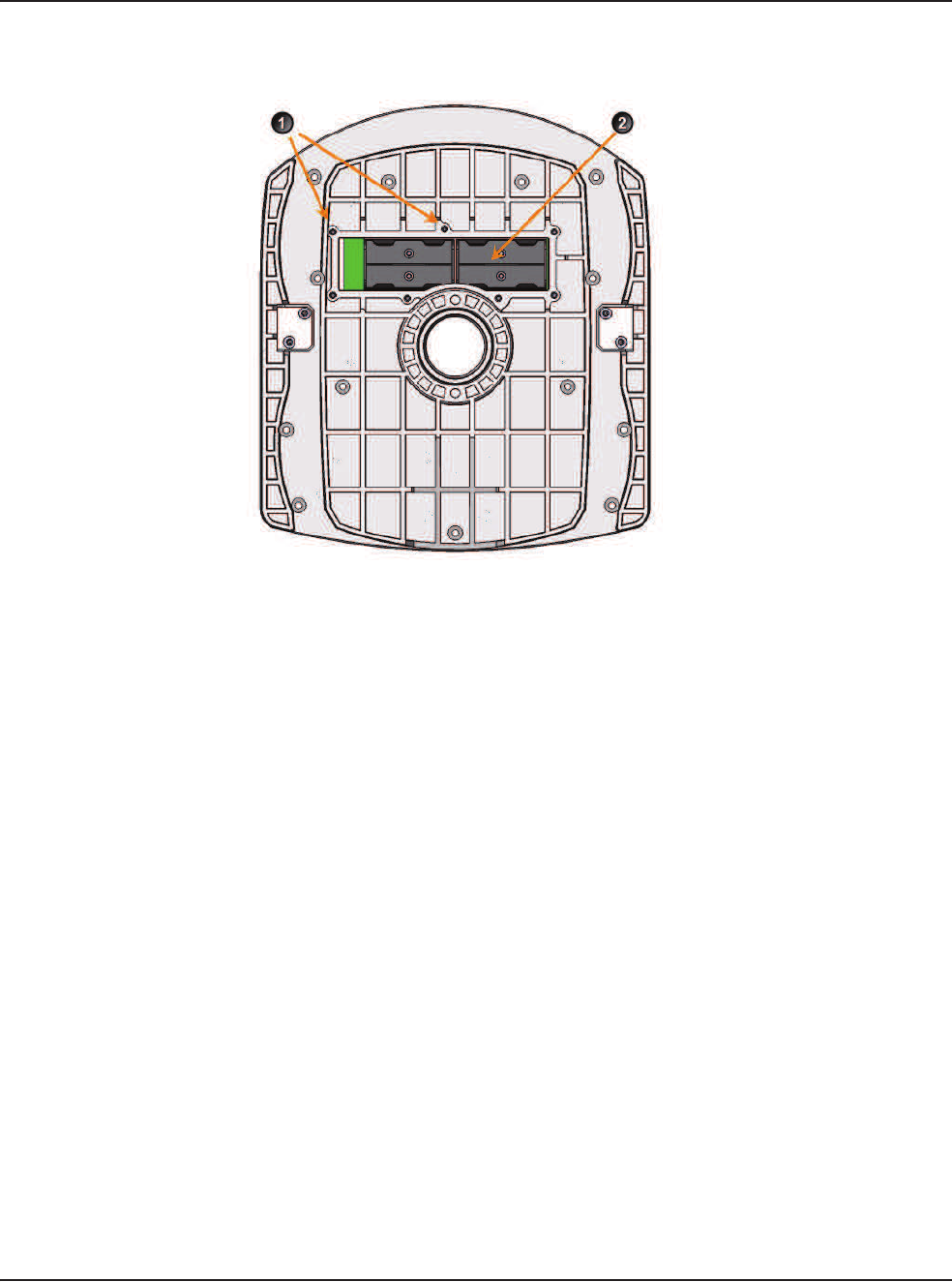
Wireless Foot Pedal
Battery Replacement
Procedure
Four AA size NiMH batteries provide power to the wireless foot pedal. You must
replace the batteries with the same size and type (NiMH) of batteries. If incorrect
batteries are used, the wrong batteries might cause damage to the foot pedal.
To replace the batteries in the foot pedal:
1. Remove the screws on the battery cover. The battery cover is located on the
bottom of the foot pedal.
2. Remove the old batteries. Do not throw the batteries in to the garbage. Use the
proper disposal method for the batteries.
3. Insert the new batteries. Make sure that the batteries are inserted correctly.
4. Replace the battery cover and tighten all of the screws.
1. Power Switch 2. Fuse Holder
1
2
10 • Error Messages Troubleshooting and Diagnostics
WHITESTAR SIGNATURE™ System Rx Only – Z370147 Rev. C 1008 10-4
Figure 10.2 – Battery Location for the Wireless Foot Pedal
1. Battery Cover Screws (7) 2. NiMH Batteries

10 • Error Messages Troubleshooting and Diagnostics
WHITESTAR SIGNATURE™ System Rx Only – Z370147 Rev. C 1008 10-5
Most Common
User-Correctable
Problems
Use the information in this section if you are not successful with the System
Check-out. Consult this section to resolve the problem before you call AMO for
technical service.
Before you call AMO for service:
• Make sure that the System is plugged in to a power recptacle.
• Make sure that there is electrical power to the receptacle.
• If there is no phacoemulsification, make sure that the phaco needle is tight on the
handpiece.
• If there is no phacoemulsification, make sure that the phaco needle is compatible
with the handpiece (for example, non-AMO™ phaco needle on an AMO™
handpiece).
• If there is no phacoemulsification, confirm that phaco needle/handpiece was not
damaged by dropping or misuse.
• If no irrigation occurs, shake the drip chamber to confirm that the ball or valve
moves freely. If there is no rattle sound, replace the drip chamber with another
disposable tubing pack.
Status, Warning and
Error Messages
The System shows Status, Warning and Error Messages on the monitor.
The message can show possible solutions or recommendations to clear the error.
The messages can indicate the available options if a component or subsystem fails.
The messages are listed in the following pages with the corrective actions to be
taken to clear the error.
Recycle Power as a Corrective Action means that you turn the System Off (through
the normal shut down procedure), wait a few seconds, and then turn the System On.
If an error cannot be corrected, document the error message before you call AMO
for technical service. Technical Service needs to know the error message to
diagnose and correct the error.
System Operation
(Error) Messages
Table 10.2 – Fluidic Controller Error Messages
Error
Number
Message Probable Cause Corrective Action
14 Vacuum Parameter Check
Failure.
Hardware failure or
program error.
Select Next Case.
15 Flow Parameter Error Hardware failure or
program error.
Select Next Case.
16 FP Yaw Parameter Error Hardware failure or
program error.
Select Next Case.

10 • Error Messages Troubleshooting and Diagnostics
WHITESTAR SIGNATURE™ System Rx Only – Z370147 Rev. C 1008 10-6
17 FP Pitch Parameter Error Hardware failure or
program error.
Select Next Case.
18 IV Check Error Hardware failure or
program error.
Select Next Case.
19 Vit Cutter Check Error Hardware failure or
program error.
Select Next Case.
101 Fluidics communication
error.
Invalid data from the IH
or communication errors.
Select Next Case.
102 Fluidics write error. Microcontroller SPI, SPI
Bus, EEPROM, or ADC
is faulty.
Cycle power.
103 Fluidics read error. Microcontroller SPI, SPI
Bus, EEPROM, or ADC
is faulty.
Cycle power.
104 Fluidics Reservoir Vacuum
Level Error.
External air pressure low.
Venturi muffler clogged.
External air valve
clogged.
External air leak.
Venturi vacuum path leak.
Vacuum sensor not
calibrated or faulty.
Reprime the System.
105 Fluidics Reservoir Leak. Venturi vacuum path leak Reprime the System.
106 Fluidics Tank Vacuum
Level Error.
Reservoir vacuum is low.
Tank vacuum path leak.
Vacuum sensor not
calibrated or faulty.
Vacuum regulator not
calibrated or faulty.
Vacuum regulator drive
circuit failure.
Reprime the System.
107 Fluidics Tank Leak. Tank vacuum path leak. Reprime the System.
Error
Number
Message Probable Cause Corrective Action

10 • Error Messages Troubleshooting and Diagnostics
WHITESTAR SIGNATURE™ System Rx Only – Z370147 Rev. C 1008 10-7
108 Fluidics Pack Vacuum
Level Error.
Reservoir vacuum is low.
Pack vacuum path leak.
Vacuum sensor not
calibrated or faulty.
Vacuum regulator not
calibrated or faulty.
Vacuum regulator drive
circuit failure.
Reprime the System.
109 Fluidics Pack Leak. Pack leak. Reprime the System.
110 Fluidics RAM error. Bad Microcontroller. Cycle power.
111 Fluidics ROM error. Bad Microcontroller. Cycle power.
112 Fluidics Master
Communication error.
Instrument Host
malfunction.
Bad microcontroller.
Cycle power.
113 Drain Pump Fault. Droplets, bubbles, or fog
on chamber walls.
Bad fluid level sensor(s).
Bad cable.
Fluid level sensor drive
circuits faulty.
Drain pump drive circuit
fault.
Check the chamber and the
bag for over-inflation.
Select Next Case.
114 Fluidics DAC Fault. Circuit failure (I2C bus,
DAC, or micro).
Reprime the System.
115 Fluidics Evacuation
Vacuum Level Error.
Reservoir vacuum is low
Evacuation vacuum path
leak
Vacuum sensor not
calibrated or faulty
Vacuum regulator not
calibrated or faulty
Vacuum regulator drive
circuit failure
Reprime the System.
116 Fluidics Evacuation Leak. Evacuation path leak. Reprime the System.
Error
Number
Message Probable Cause Corrective Action

10 • Error Messages Troubleshooting and Diagnostics
WHITESTAR SIGNATURE™ System Rx Only – Z370147 Rev. C 1008 10-8
117 Fluidics Fluid Level Sense
Error.
Droplets, bubbles, or fog
on chamber walls.
Bad fluid level sensor(s).
Bad cable.
Fluid level sensor drive
circuits faulty.
Check the chamber and the
bag for over-inflation.
Select Next Case.
118 Fluidics Irrigation Valve
error.
Valve failure.
Drive circuit failure.
Cycle power.
119 Fluidics Pinch Valve error. Valve failure.
Drive circuit failure.
Cycle power.
120 Fluidics Silicone Extraction
Valve Fault
Valve failure.
Drive Circuit failure.
Disable Venturi or select
Next Case.
121 Fluidics Pack Alignment
Valve Fault.
Pump failure.
Drive circuit failure.
Reinsert the pack and
reprime.
122 Fluidics Dump Valve Fault. Valve failure.
Drive circuit failure.
Disable Venturi or select
Next Case.
123 Fluidics Venturi Valve
Fault.
Valve failure.
Drive circuit failure.
Disconnect compressed air.
Reprime the system.
124 Fluidics Rotary Vane Fault. Pump failure.
Drive circuit failure.
Connect compressed air.
Reprime the system.
125 Fluidics Pack Valve error. Valve failure.
Drive circuit failure.
Cycle power.
127 Fluidics Valve Vent error. Irrigation blocked. 1. End the current Case.
2. Start a New Case.
3. Reprime the System.
4. Turn the system off, wait a
few seconds, then turn the
system on.
5. Install a new tubing
cassette
6. If the error does not clear or
if the error continues to
occur, document the Error
Message and contact AMO
for technical service.
128 Fluidics Pack Loading
error.
Pack not properly seated. Reload the tubing cassette.
Reprime.
129 Fluidics Proportional Valve
Fault.
Valve failure.
Drive circuit failure.
Disconnect compressed air.
Reprime the system.
Error
Number
Message Probable Cause Corrective Action

10 • Error Messages Troubleshooting and Diagnostics
WHITESTAR SIGNATURE™ System Rx Only – Z370147 Rev. C 1008 10-9
130 Fluidics Encoder error. Pack loading problem.
Encoder is faulty.
Decoder circuit is faulty.
Stepper driver circuit is
faulty.
Reload the tubing cassette.
Select Next Case.
131 Fluidics Mode error. Instrument Host
malfunction.
Bad SSC Board.
Bad footpedal.
Cycle power.
132 Fluidics VAC regulator
current is too high or too
low.
Vacuum regulator faulty.
Drive circuit faulty.
Disable Venturi or select
Next Case.
133 Fluidics strain gauge ADC
error.
ADC is faulty. Cycle power.
134 Fluidics Drain Pump
Rotational Error.
Pack loading problem.
Encoder is faulty.
Decoder circuit is faulty.
Stepper driver circuit is
faulty.
Insert Fusion™ Pack or
select Next Case.
Reprime the system.
135 Low external air pressure. Leak in external air
supply path.
Pressure regulator set too
low.
Pressure sensor faulty.
Reinsert the pack and
reprime.
Check the external air
supply.
136 Fluidics VAC Regulator
Vent Fault.
Pinch valve is blocked. Disable Venturi or select
Next Case.
137 Footpedal error. Bad footpedal or user
depressing footpedal.
Release the footpedal.
Disconnect and reconnect
footpedal.
Cycle power and retry.
138 Tank fluid level has reached
the top sensor.
Drain pump cannot keep
up with the input of fluid.
Please wait for the tank to
drain
144 Fluidics Vacuum Senors
Disagree Error.
Leak in vacuum path
Vacuum sensor faulty.
Reinsert the pack and
reprime.
147 Reservoir vacuum is too
low. Target vacuum cannot
be reached.
Leak
Vacuum regulator faulty
Drive circuit faulty
Select Next Case.
Reprime the system.
Error
Number
Message Probable Cause Corrective Action

10 • Error Messages Troubleshooting and Diagnostics
WHITESTAR SIGNATURE™ System Rx Only – Z370147 Rev. C 1008 10-10
148 Pressure to pack capture
mechanism is less than 60
psi.
Leak Reinsert the pack and
reprime.
149 Unloaded strain gauge
reading is too high or too
low.
Pack not loaded correctly. Reinsert the pack and
reprime.
201 Phaco Communication
error.
Bad data sent from host. Retune or cycle power.
202 Phaco power error. Hardware failure (phaco
driver).
Retune or cycle power.
203 Phaco handpiece error. Bad handpiece. Retune or cycle power.
Replace the phaco handpiece.
204 Phaco handpiece error. Wire in handpiece broken. Retune or cycle power.
Replace the phaco handpiece.
207 Incompatible Handpiece
Error.
Incompatible handpiece. 1. Turn off Ellips™
Technology.
2. Attach the Ellips™
handpiece.
3. Tune the handpiece.
210 Phaco RAM error. Chip is bad. Cycle power.
211 Phaco ROM error. Bad 196 processor. Cycle power.
212 Phaco controller timeout. Host stopped writing to
the Phaco controller.
Cycle power.
281 Phaco communication
error.
Software bug or Hardware
failure.
Cycle power.
282 Phaco error. Bad handpiece. Check handpiece and retune.
283 Phaco error. Driver failure. Check handpiece and retune.
Replace the handpiece and
tune.
284 Phaco power supply error. Bad Power Supply. Cycle power or call service.
285 Check for loose handpiece
and retune.
Tip is loose. Check for loose handpiece
tip and retune.
Replace the handpiece and
tune.
286 Phaco handpiece impedance
error.
Bad handpiece. Check handpiece and retune.
Replace the handpiece and
tune.
Error
Number
Message Probable Cause Corrective Action

10 • Error Messages Troubleshooting and Diagnostics
WHITESTAR SIGNATURE™ System Rx Only – Z370147 Rev. C 1008 10-11
288 Diathermy error. DIA subsystem issue. Check handpiece.
Select Next Case or cycle
power.
290 Footpedal error. Bad footpedal or user
pressing the footswitch.
Check footpedal. Cycle
power.
291 Phaco Diathermy power
supply error.
Software or hardware
failure.
Cycle power.
301 Pneumatics RAM error. Microcontroller failure. Cycle power.
302 Pneumatics ROM error. Microcontroller failure. Cycle power.
303 Pneumatics Master
communication error.
Watchdog event.
PC104 Bus failure.
Micro failure.
CPLD failure.
Cycle power.
307 Pneumatics communication
error.
Invalid data received by
the IH or communication
error.
Cycle power.
308 External air pressure high/
low.
Valve failure.
Drive circuit failure.
Check compressed air
supply.
Select Next Case.
309 Piston pump pressure high/
low.
Pump failure.
Drive circuit failure.
Select Next Case.
310 Vit selector valve pressure
high/low.
VIT Selector Valve
failure.
Drive circuit failure.
Select Next Case.
311 Dump valve pressure high/
low.
VIT Dump Valve failure.
Drive circuit failure.
Select Next Case.
312 Cut valve pressure high/
low.
VIT Cut Valve failure.
Drive circuit failure.
Select Next Case.
322 Pneumatics system pressure
too low.
V1 External Air valve not
open.
Piston Pump not working.
System leak.
Dump valve not closing.
Vitrectomy Cut valve
always on.
Select Next Case.
Error
Number
Message Probable Cause Corrective Action

10 • Error Messages Troubleshooting and Diagnostics
WHITESTAR SIGNATURE™ System Rx Only – Z370147 Rev. C 1008 10-12
323 Pneumatics system pressure
too low.
PP1 Piston Pump not
working.
Piston Pump not working.
System leak.
Dump valve not closing.
Vitrectomy Cut valve
always on.
Select Next Case.
327 Pneumatics system pressure
too low at the high cut rates.
PP1 Piston Pump not
working.
Piston Pump not working.
System leak.
Dump valve not closing.
Vitrectomy Cut valve
always on.
Selector valve is not
changing.
Select Next Case.
336 Pneumatics system pressure
too low at the low cut rates.
PP1 Piston Pump not
working.
Piston Pump not working.
System leak.
Dump valve not closing.
Vitrectomy Cut valve
always on.
Selector valve is not
changing.
Select Next Case.
353 IH to GUI Communication
Timed Out.
Software error or
hardware error.
Select Next Case.
360 IH Fluidics – read error. Communication error. Cycle power.
361 IH Fluidics – write error. Communication error. Cycle power.
362 H Fluidics – Comm. error. Communication error. Cycle power.
370 IH Phaco read error. Communication error. Cycle power.
371 IH Phaco write error. Communication error. Cycle power.
372 Bad Phaco long pulse. Communication error. Check program setting.
Cycle power.
373 IH Invalid Phaco burst
setting.
Communication error. Check program. Cycle
power.
374 Handpiece removed during
Phaco.
No handpiece is
connected.
1. Attach a handpiece.
2. Tune the handpiece.
Error
Number
Message Probable Cause Corrective Action

10 • Error Messages Troubleshooting and Diagnostics
WHITESTAR SIGNATURE™ System Rx Only – Z370147 Rev. C 1008 10-13
375 Incompatible HP. Attempted to use Ellips™
Phaco settings with a
WHITESTAR®
handpiece.
1. Turn off Ellips™
Technology.
2. Attach the Ellips™
handpiece.
3. Tune the handpiece.
380 IH Pneumatics – read error. Communication error. Cycle power.
381 IH Pneumatics – write
error.
Communication error. Cycle power.
390 IH Diag read error. Communication error. Cycle power.
391 IH Diag write error. Communication error. Cycle power.
416 Footpedal communication
error.
Could not open port.
Footpedal not responding.
Reconnect footpedal.
418 Footpedal compatibility
error.
New footpedal firmware. Replace footpedal.
501 Prime excessive vacuum
error.
Communication error. Check the tubing cassette.
Reload or replace the tubing
cassette.
Reprime.
502 Prime low bottle height
error.
Bottle not at the proper
height.
Increase bottle height and
reprime.
503 Prime low vacuum error. Hardware failure. Check the tubing cassette.
Reload or replace the tubing
cassette.
Reprime.
507 Prime EQ pressure error. Hardware failure. Reprime.
508 Prime low venturi vacuum
error.
Hardware failure. Reprime.
511 IV Pole communications
error.
Communication error. Reprime the system.
512 IV Pole communications
error.
Communication error. Reprime the system.
513 IV Pole communications
error.
Communication error. Reprime the system.
514 IV Pole error. Communication error. Reprime the system.
Error
Number
Message Probable Cause Corrective Action

10 • Error Messages Troubleshooting and Diagnostics
WHITESTAR SIGNATURE™ System Rx Only – Z370147 Rev. C 1008 10-14
515 IV Pole calibration error. Communication error. Reprime the system.
516 IV Pole communication
error.
Communication error. Reprime the system.
517 IV Pole jammed. Jammed.
Motor failure.
A “Short” in the motor
wires.
Obstruction is not
allowing the pole to move
Check for obstructions.
Reprime the system.
601 Tune excessive vacuum
error.
Hardware failure. Check the tubing and the
connections to the handpiece.
Retune.
605 Tune no handpiece error. Hardware failure. Insert handpiece and retune.
2000 DLL CRC Error DLL checksum does not
match config.dat.
Cycle power.
2001 CRC Error STR checksum does not
match config.dat.
Cycle power.
2002 Database Self Test Error Database file checksum
does not match config.dat.
Cycle power.
2003 Error updating database
file.
Error when database was
saved.
Cycle power.
2004 Error adding language. Error during the Install
Language session.
Cycle power.
2005 Error reading USB memory
stick.
Error during an Import or
Export session.
Cycle power.
2006 Error loading DLL. Cannot find or load a DLL
file.
Cycle power.
2007 Record file save error. Error when Record
database file was saved.
Cycle power.
2008 Error reading Record file. Cannot read Record
database file.
Cycle power.
2010 IH Communication timed
out.
No communication with
the IH.
Cycle power.
Error
Number
Message Probable Cause Corrective Action

10 • Error Messages Troubleshooting and Diagnostics
WHITESTAR SIGNATURE™ System Rx Only – Z370147 Rev. C 1008 10-15
Troubleshooting Table 10.3 – Troubleshooting – General
2011 Error retrieving version
strings from IH.
Cannot not retrieve the IH
version numbers.
Cycle power.
2012 IH timeout error. No communication with
IH.
Cycle power.
2014 IH Selftest error. Cannot get Selftest status
from the IH.
Cycle power.
Error
Number
Message Probable Cause Corrective Action
General
Problem Corrective Action
The System does not come
on when the power switch
is turned on.
1. Turn the power switch Off.
2. Confirm that the power cord is connected to the console back panel.
3. Confirm that the power cord is plugged into the electrical receptacle or
another power source.
4. Confirm that there is electrical power to the wall receptacle or power
source.
5. Turn the system On.
6. If the system still does not come on, turn the power Off. Check for bad
fuses and replace the fuse if necessary.
7. Contact AMO for Technical Service.

10 • Error Messages Troubleshooting and Diagnostics
WHITESTAR SIGNATURE™ System Rx Only – Z370147 Rev. C 1008 10-16
The wireless remote control
does not pair.
1. Make sure that you are pairing only one remote. If you try to pair more
than one remote at the same time, the pairing fails.
2. Only pair the remote with one console at a time. Do not press the
pairing key sequence on multiple remote controls as this causes the pairing
to fail.
3. Do not have any other Bluetooth™ devices in the same area as the
remote and the console (other remote controls, dual linear foot pedals, cell
phones, or headsets, for example) as the pairing operation will fail. The
software only detects a maximum of nine (9) devices any more than nine
and the pairing fails.
4. Check to see if the remote control is in “Sleep” mode. If the remote is
in “Sleep” mode, press the Backlight button on the remote. Complete the
UP, DOWN, RIGHT, LEFT, RELOAD key sequence to pair the remote.
Note: Always press the Backlight button before you pair the remote.
5. The remote control can only be paired with one console at a time.
Make sure that the remote has not been paired with another console. You
must:
• Unpair the remote from the console.
• Shut down the console.
• Pair the remote with the new console. Make sure this console is at
least 40 meters away from the first console.
6. The remote cannot be paired with another console after that remote has
been paired. (You cannot pair one remote with two (2) consoles.)
• Unpair the remote from the console.
• Move the first remote out of range from the console.
• Wait for the first remote to go into “Sleep” mode.
• Pair the new remote.
7. Make sure that the batteries are fully charged before you pair the
remote with the console. Low batteries can cause pairing failures.
8. Charge the batteries if pairing has failed after several attempts.
9. When the batteries are charging (the remote is in the charge cradle):
• The Bluetooth™ is turned off
• The remote cannot be used
• Pairing cannot be performed
General
Problem Corrective Action

10 • Error Messages Troubleshooting and Diagnostics
WHITESTAR SIGNATURE™ System Rx Only – Z370147 Rev. C 1008 10-17
Dual Linear Foot Pedal
does not pair.(Advanced
Control Pedal)
1. Make sure that the foot pedal is not paired with another console.
2. Do not have any other Bluetooth™ devices in the same area as the foot
pedal and the console (other remote controls, dual linear foot pedals, cell
phones, or headsets, for example) as the pairing operation will fail. The
software only detects a maximum of nine (9) devices any more than nine
and the pairing fails.
3. Make sure that the batteries are fully charged before you pair the foot
pedal with the console. Low batteries can cause pairing failures.
4. Charge the batteries if pairing has failed after several attempts.
5. When the batteries are charging (the foot pedal is in the charge cradle):
• The Bluetooth™ is turned off
• The foot pedal cannot be used
• Pairing cannot be performed
The footpedal is not
operating properly.
1. Go to the Diagnostics section and perform a Footpedal Test.
2. Confirm the footpedal cord is connected at the back of the console.
3. Confirm the footpedal is paired to the System, for the Advanced
Control Pedal (dual linear) only.
4. Perform a Foot Pedal Calibration, for the Advanced Control Pedal
(dual linear) only.
5. Replace the wireless footpedal batteries, Advanced Control Pedal
(dual linear) only.
The Programmable IV Pole
does not respond.
1. The pole might have reached maximum or minimum height.
2. Attempt a Programmable IV Pole height adjustment with the touch
screen, remote, or the up and down switch on the side of the system.
The Touch Screen does not
respond.
Perform the Touch Screen Calibration procedure as described in
Diagnostics.
Priming Errors. 1. Check the tubing pack loading, including reloading the tubing cassette.
2. Verify that there are no kinks, clogs, or loose fittings.
3. Replace the handpiece and the tip and prime.
4. Replace the tubing cassette.
5. Check the test chamber for proper installation and leaks.
6. Contact AMO Technical Service to check the vacuum.
General
Problem Corrective Action

10 • Error Messages Troubleshooting and Diagnostics
WHITESTAR SIGNATURE™ System Rx Only – Z370147 Rev. C 1008 10-18
Table 10.4 – Troubleshooting – Irrigation
Irrigation
Problem Corrective Action
No irrigation flow. 1. Make sure the appropriate mode is selected on the screen.
2. Check for kinks in the irrigation tubing.
3. Check the tubing connection to the handpiece.
4. Tap the drip chamber to make sure the valve operates properly.
5. Check the bottle height.
6. Press the footpedal to Position 1 and check for flow.
7. Listen for the irrigation pinch valve in the tubing manifold area to
confirm that the valve operates when the footpedal is pressed.
8. If there is still no flow, replace the tubing cassette.
Reduced/insufficient
irrigation flow.
1. Check for kinks in the tubing or leaks in the tubing or the handpiece.
2. Check the bottle height.
3. Check the tubing connections.
4. Check for a pinched irrigation sleeve at the incision.
Irrigation flow continues
even when footpedal is Off
(Position 0).
1. Check that the footpedal is not obstructed and not stuck in P 1.
2. Check the footpedal operation.
3. Verify that Continuous Irrigation is not active.
Anterior chamber is too
shallow or too deep.
1. Check the bottle height.
2. Too shallow, check for a pinched irrigation sleeve at the incision.
3. Check the pump speed (flow rate).
4. Check that the irrigation tubing is not obstructed.
5. Make sure Irrigation and Aspiration are balanced.
Using large amounts of
fluid.
1. Check the bottle height.
2. Check the incision size.
3. Check the flow rate (pump speed too high).
4. Check that no fluid enters the collection bag when you do not use
irrigation.
5. Reseat or replace the tubing.

10 • Error Messages Troubleshooting and Diagnostics
WHITESTAR SIGNATURE™ System Rx Only – Z370147 Rev. C 1008 10-19
Table 10.5 – Troubleshooting – Aspiration
Aspiration
Problem Corrective Action
No aspiration. 1. Make sure the appropriate mode is selected on the screen.
2. Check for kinks or clogs in the tubing.
3. Check the tubing connection to the handpiece.
4. Make sure that the handpiece is not clogged.
5. Press the footpedal to Position 2 and check the pump function.
Poor aspiration. 1. Check the flow rate.
2. Check the footpedal operation.
3. Check for kinks or clogs in the tubing.
4. Make sure that the handpiece is not clogged.
5. Check the tubing connection to the handpiece.
6. Check the IA handpiece o-rings for excessive wear. Replace the
o-rings, if needed.
Not building vacuum.
Pump does not turn.
1. Check the programming. If the surgeon is in “linear vacuum” as
opposed to “linear aspiration”, the footpedal must be pressed through
Position 2 for the vacuum to reach the preset maximum.
2. Make sure the footpedal is pressed.
3. Check the tubing connection to the handpiece.
4. Check for air in the irrigation and aspiration tubing.
5. Check the system vacuum settings.
6. Replace the tubing cassette
7. Run IA Prime.
8. Check the flow rate.
Chamber shallowing or
partially collapses.
1. Check the bottle height and the handpieces for correct position.
2. Check the flow rate setting.
3. Check the tubing fittings to the handpiece.
4. Check for kinks in the tubing.
5. Remove the handpiece and perform the test chamber test to make sure
the handpiece is balanced.
6. Make sure Irrigation and Aspiration are balanced.

10 • Error Messages Troubleshooting and Diagnostics
WHITESTAR SIGNATURE™ System Rx Only – Z370147 Rev. C 1008 10-20
Table 10.6 – Troubleshooting – Phacoemulsification
Table 10.7 – Troubleshooting – Diathermy
Phacoemulsification
Problem Corrective Action
No phacoemulsification. 1. Make sure that the PHACO mode is selected on the touch screen.
2. Make sure that the System is Primed and Tuned.
3. Check the footpedal operation.
4. Make sure that the phaco handpiece cord is properly connected to the
phaco receptacle on the front of the system.
5. Check the Phaco Power setting.
6. Make sure that the phaco tip is tight on the handpiece.
7. Check to make sure that the phaco tip is not damaged.
8. If the tip is damaged, replace the tip with a new tip and retune.
Poor or intermittent
phacoemulsification.
1. Check all of the corrective steps above for “No Phacoemulsification”.
2. Remove the phaco tip and then replace the tip. Make sure the tip is
tight on the handpiece.
3. Check the Phaco Power delivery setting for both unoccluded and
occluded (if applicable) settings.
4. Tune the phaco handpiece.
Diathermy
Problem Corrective Action
No diathermy or poor
diathermy.
1. Make sure that the Diathermy mode is selected on the touch screen.
2. Check the footpedal operation.
3. Check the Diathermy Power setting.
4. Check the diathermy cord for a secure connection to the forceps and to
the diathermy receptacles on the system.
5. Make sure that the diathermy cord connections are dry.
6. Try to use diathermy starting at a low power setting and gradually
increase the power.
7. Replace the diathermy cord.
8. Replace the diathermy handpiece.
No sound when using
diathermy.
1. Make sure the Volume Setting is set at 6 or greater in Settings.
2. Check for sounds when you push any touch screen or remote buttons.
3. Check for an audible confirmation upon completion of system start-up
test (at power up).
4. Perform the Sound Test on the Diagnostics screen.

10 • Error Messages Troubleshooting and Diagnostics
WHITESTAR SIGNATURE™ System Rx Only – Z370147 Rev. C 1008 10-21
Table 10.8 – Troubleshooting – Vitrectomy
Vitrectomy
Problem Corrective Action
No vitrectomy cutting or
poor cutting.
1. Make sure that the Vitrectomy mode is selected on the touch screen.
2. Verify that the surgeon is in footpedal Position 3, if IAC step
vitrectomy is programmed. If ICA is programmed, verify the footpedal is
in Position 2.
3. Check the footpedal operation.
4. Check the tubing connections to the vitrectomy cutter.
5. Check the vitrectomy tubing connection to the front panel receptacle
on the system.
6. Check the Vitrectomy Rate (CPM) setting on the touch screen. Lower
the CPM, if necessary.
7. Check that irrigation and aspiration are working correctly.
8. Verify that the cutter blade moves.
9. Replace the vitrectomy cutter and try again.

WHITESTAR SIGNATURE™ System Rx Only – Z370147 Rev. C 1008 11-1
Warranty Statement
11 WARRANTY AND MAINTENANCE

11 • Warranty and Maintenance
WHITESTAR SIGNATURE™ System Rx Only – Z370147 Rev. C 1008 11-2
Warranty Statement AMO warrants for a period of two years (24 months) from the date of installation of
the WHITESTAR SIGNATURE™ System console, footpedal, wireless remote
control, programmable power pole and the phaco handpiece to be free from defects
in materials and workmanship when properly installed, maintained, and used for
the intended purpose.
MISUSE AND MISHANDLING ARE NOT COVERED UNDER WARRANTY.
AMO’s sole obligation is to repair or replace, at AMO’s option, the defective
part(s).
The Irrigation/Aspiration Handpiece Set, Diathermy Forceps and Diathermy Cord
are warranted for ninety (90) days.
This warranty applies only to the original purchaser/user of the device and only so
long as the equipment is used in the country to which it was originally shipped by
AMO.
THIS WARRANTY IS IN LIEU OF ALL OTHER WARRANTIES, EXPRESSED
OR IMPLIED, INCLUDING WITHOUT LIMITATION THE WARRANTIES OF
MERCHANTABILITY OR FITNESS FOR A PARTICULAR PURPOSE. IN NO
EVENT SHALL AMO BE LIABLE TO THE PURCHASER FOR
CONSEQUENTIAL DAMAGES.
Extended Warranty
Extended Warranty Contracts (excluding the phaco handpiece) are available.
Contact AMO for information on the availability of an Extended Warranty
Contract.
Note: If outside the United States, contact your local AMO office or
representative for warranty information.
Maintenance
User maintenance of the WHITESTAR SIGNATURE™ System is limited to those
adjustments and corrective actions given in the Error Messages and
Troubleshooting, and Diagnostics sections of this manual. There are no user
serviceable components within the machine and you must not attempt to access the
internal components. Any attempt to do so will void the warranty.
Routine or periodic maintenance of the WHITESTAR SIGNATURE™ System by
an AMO representative is recommended at least annually. AMO recommends the
measurement of PE resistance and leakage current according to IEC 601-1 every
two years.
If a problem continues following setup, check-out and troubleshooting as per the
procedures given in this manual, contact AMO for corrective action (1-877-AMO-
4LIFE in USA 1-877-266-4543). Please contact your local AMO office or
representative for region-specific phone numbers.

WHITESTAR SIGNATURE™ System Rx Only – Z370147 Rev. C 1008 12-1
Physical Specifications
Environmental Specifications
Electrical Specifications
Diathermy Specifications
Irrigation and Aspiration Specifications
Phacoemulsification Specifications
Vitrectomy Specifications
Diathermy Power Graphs
Diathermy Power versus Load Impedance
Phaco Power Graphs
12 SPECIFICATIONS

12 • Specifications
WHITESTAR SIGNATURE™ System Rx Only – Z370147 Rev. C 1008 12-2
Physical
Specifications
Table 12.1 – System Physical Specifications
English /
U.S.
Metric:
WHITESTAR SIGNATURE™ System Console:
Console Dimensions (with
display)
Width 24 inches 61 cm
Depth 24 inches 61 cm
Height 54 inches 137 cm
Power Cord Length 20 feet 6 meters
Electrical Enclosure Current
Leakage
IEC 60601-1
compliance
UL 60601-1
Weight (including IV pole) 195 pounds 88.5 kg
Footpedal:
Single Linear
Dimensions Width 12 inches 31 cm
Length 10.5 inches 27 cm
Height 5.5 inches 14 cm
Weight 10.0 pounds 4.5 kg
Advanced Control Pedal
(Dual Linear)
Dimensions Width 10.5 inches 27 cm
Length 14 inches 36 cm
Height 5.5 inches 14 cm
Weight 15 pounds 7 Kg
Cord Length 11.8 feet 36 cm
Power IV Pole:
Maximum Travel 41 inches 107 cm
Velocity 2.4 inches/sec 6 cm/sec.
Maximum Lift Weight 2.43 pounds 1.1 kg
Wireless Remote Control
Width 5 inches 13 cm
Length 5 inches 13 cm
Height 1.5 inches 4 cm
Weight 2.0 pounds .9 kg

12 • Specifications
WHITESTAR SIGNATURE™ System Rx Only – Z370147 Rev. C 1008 12-3
Environmental
Specifications
Table 12.2 – Environmental Specifications
Electrical
Specifications
Table 12.3 – Electrical Specifications
Diathermy
Specifications
Table 12.4 – Diathermy Specifications
Irrigation and
Aspiration
Specifications
Table 12.5 – Irrigation and Aspiration Specifications
Environmental
Specifications
Operating Temperature
Humidity
10 to 40°C
Up to 95% RH,
non-condensing
Storage/Transportation
Conditions
Storage Temperature
Humidity
-20 to 60°C
Up to 95% RH,
non-condensing
Voltage Frequency Rated Power Fuse Rating Enclosure
Current Leakage
System 100/120/240
Vac
50/60 Hz 750 VA 6.3A, 250V,
Bussman
GDA
<500 uA
Diathermy
Specifications
Power Adjustment
Diathermy Power (maximum power
into rated load)
Diathermy Type
5 to 100%, in 5% increments
8.5 Watts into 350 ohms 386 KHz
Bipolar
IA Specifications
Peristaltic Pump Vacuum Level 0–650 mmHg in 5 mmHg increments
Pump Flow 0 to 60 cc/minute
Venturi Pump Vacuum Level 0-600 mmHg in 5 mmHg increments

12 • Specifications
WHITESTAR SIGNATURE™ System Rx Only – Z370147 Rev. C 1008 12-4
Phacoemulsification
Specifications
Table 12.6 – Phacoemulsification Specifications
Vitrectomy
Specifications
Table 12.7 – Vitrectomy Specifications
Phacoemulsification
Specifications
Phaco Power 0 to 100%, in 5% increments
Peristaltic Pump Vacuum Level 0–650 mmHg in 5 mmHg increments
Pump Flow Rate 0 to 60 cc/minute
Venturi Pump Vacuum Level 0-600 mmHg in 5 mmHg increments
Vitrectomy Specifications
Peristaltic Pump Vacuum Level 0–650 mmHg in 5 mmHg increments
Pump Flow Rate 10 to 60 cc/minute, in 2 cc increments
Venturi Pump Vacuum Level 0-600 mmHg in 5 mmHg increments
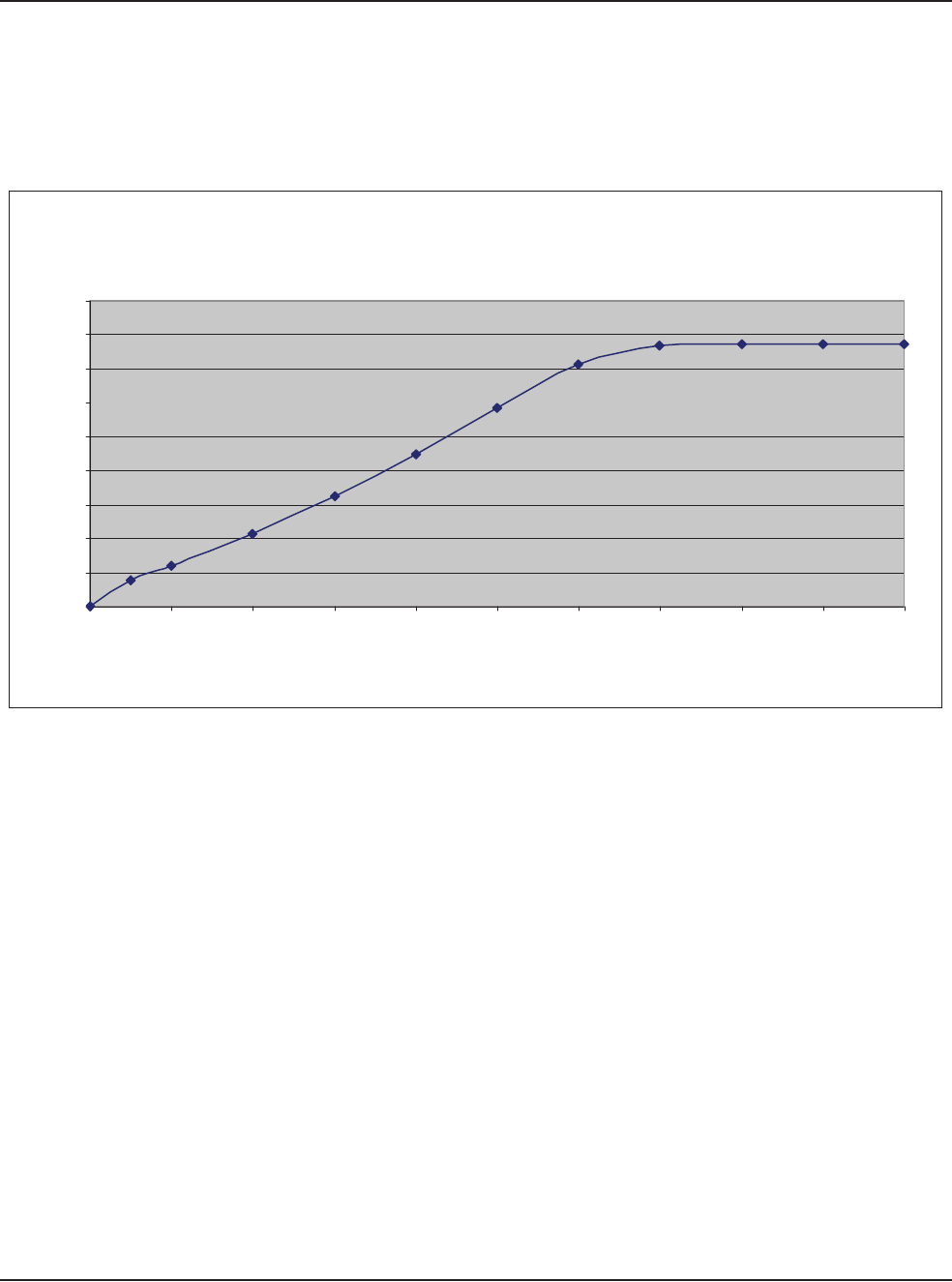
12 • Specifications
WHITESTAR SIGNATURE™ System Rx Only – Z370147 Rev. C 1008 12-5
Diathermy Power
Graphs
Table 12.8 – Diathermy Output Power (Typical) 50 Ohm
Diathermy Output Power (Typical)
50 Ohm
0
0.5
1
1.5
2
2.5
3
3.5
4
4.5
0 10 20 30 40 50 60 70 80 90 100
Control Panel Settings (%)
Output Power (Watts) +/- 20%
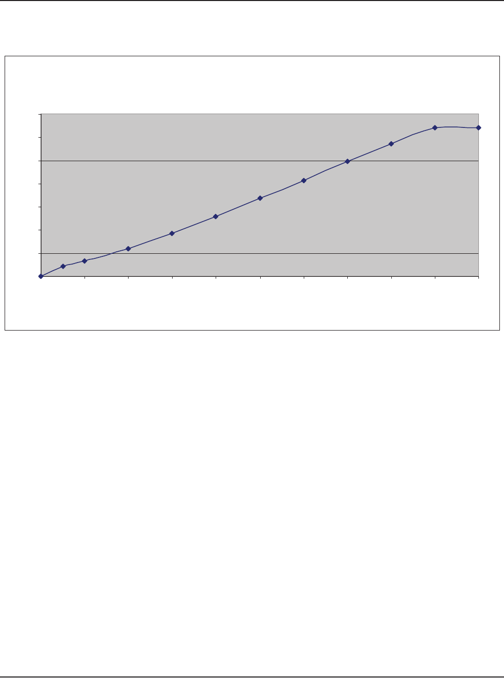
12 • Specifications
WHITESTAR SIGNATURE™ System Rx Only – Z370147 Rev. C 1008 12-6
Table 12.9 – Diathermy Output Power (Typical) 100 Ohm
Diathermy Output Power (Typical)
100 Ohm
0
1
2
3
4
5
6
7
0 10 20 30 40 50 60 70 80 90 100
Control Panel Settings (%)
Output Power (Watts) +/- 20%
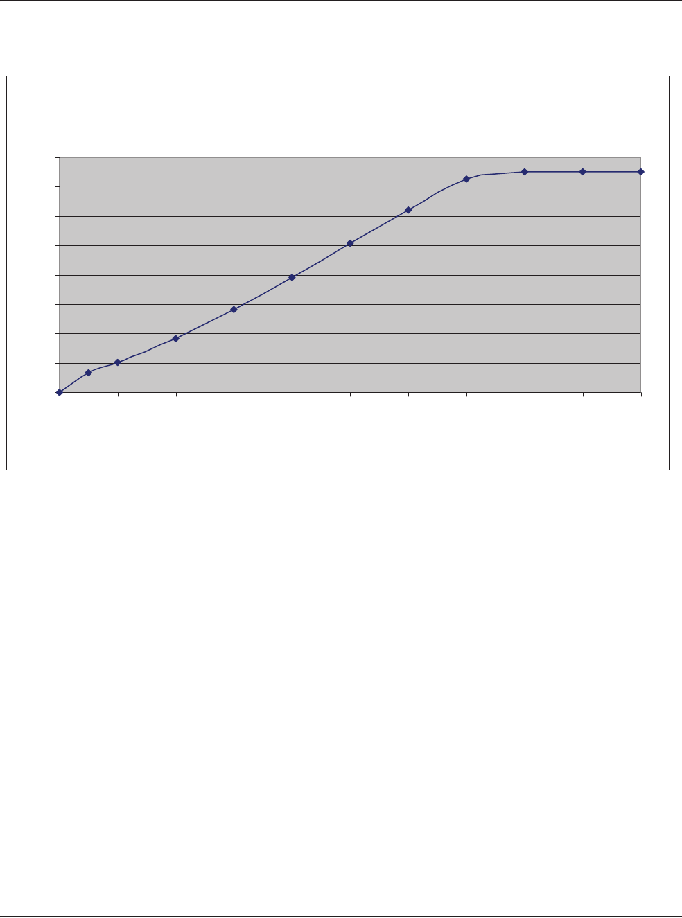
12 • Specifications
WHITESTAR SIGNATURE™ System Rx Only – Z370147 Rev. C 1008 12-7
Table 12.10 – Diathermy Output Power (Typical) 200 Ohm
Diathermy Output Power (Typical)
200 Ohm
0
1
2
3
4
5
6
7
8
0 10 20 30 40 50 60 70 80 90 100
Control Panel Settings (%)
Output Power (Watts) +/- 20
%
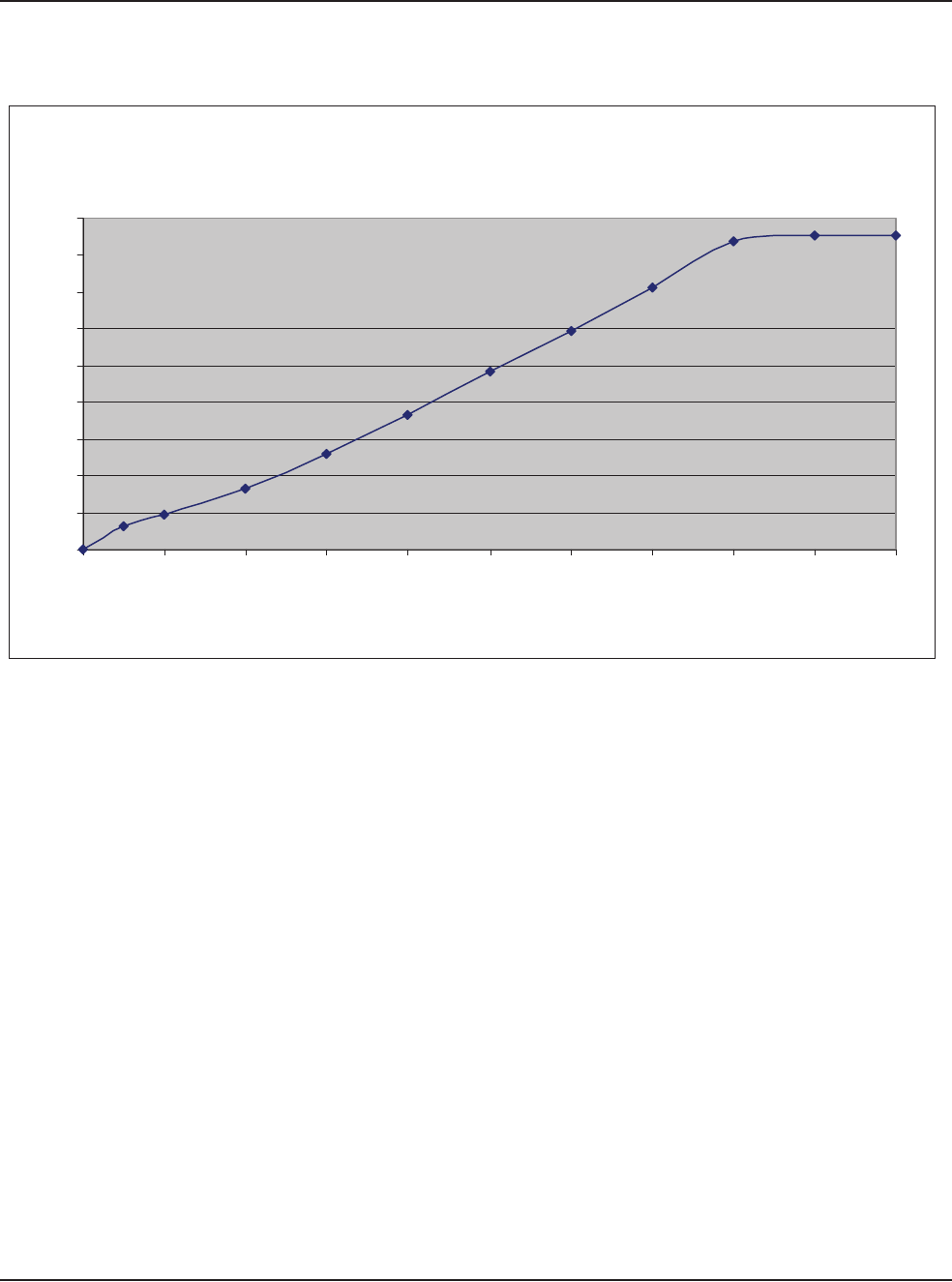
12 • Specifications
WHITESTAR SIGNATURE™ System Rx Only – Z370147 Rev. C 1008 12-8
Table 12.11 – Diathermy Output Power (Typical) 500 Ohm
Diathermy Output Power (Typical)
500 Ohm
0
1
2
3
4
5
6
7
8
9
0 10 20 30 40 50 60 70 80 90 100
Control Panel Settings (%)
Output Power (Watts) +/- 20
%
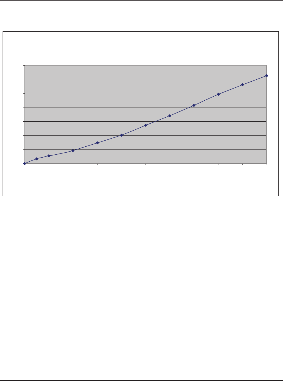
12 • Specifications
WHITESTAR SIGNATURE™ System Rx Only – Z370147 Rev. C 1008 12-9
Table 12.12 – Diathermy Output Power (Typical) 1000 Ohm
Diathermy Output Power (Typical)
1000 Ohm
0
1
2
3
4
5
6
7
0 10 20 30 40 50 60 70 80 90 100
Control Panel Settings (%)
Output Power (Watts) +/- 20%
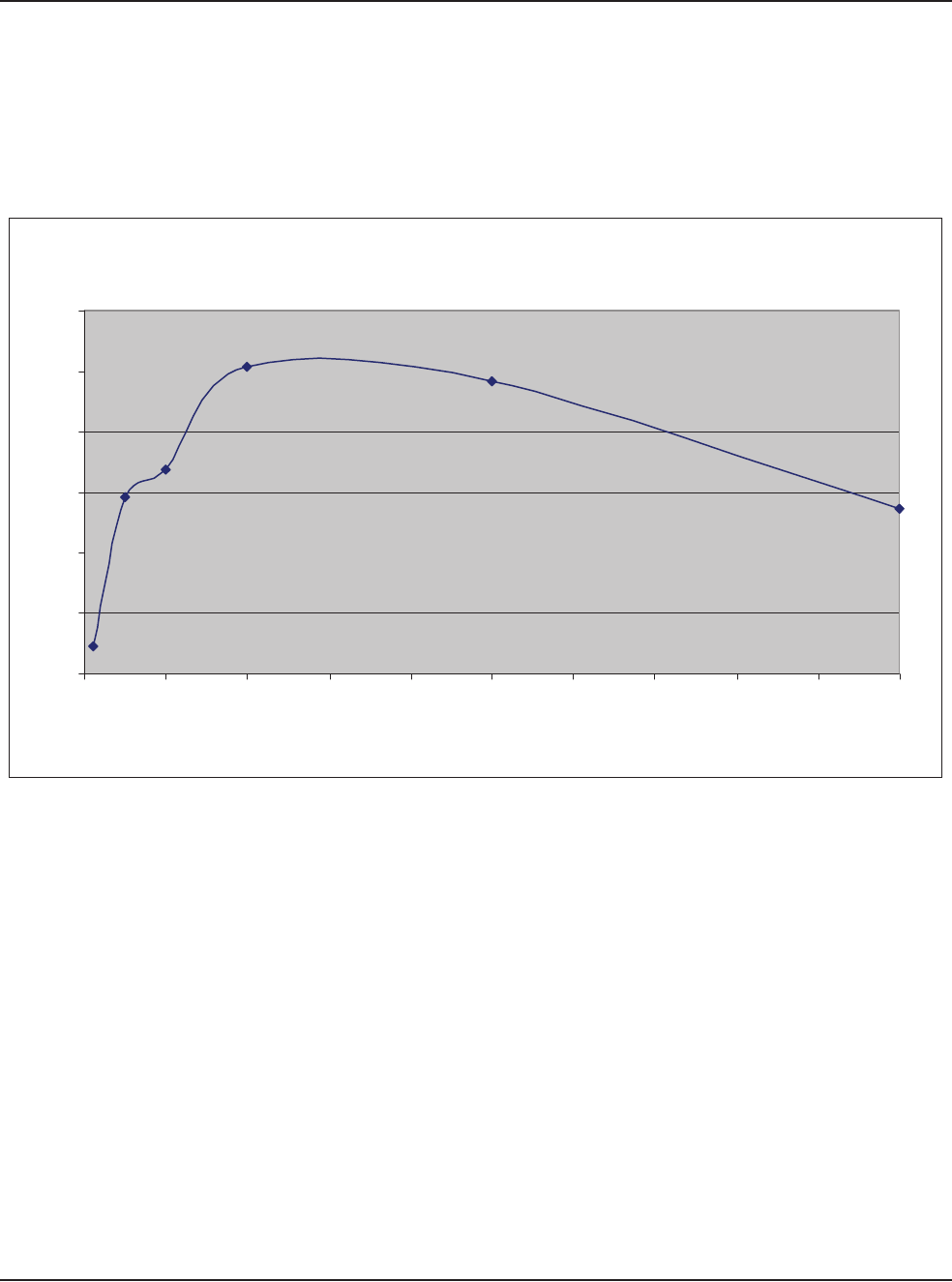
12 • Specifications
WHITESTAR SIGNATURE™ System Rx Only – Z370147 Rev. C 1008 12-10
Diathermy Power
versus Load
Impedance
Table 12.13 – Diathermy Output Power (50% Setting)
Diathermy Output Power (50% Setting)
0
1
2
3
4
5
6
0 100 200 300 400 500 600 700 800 900 1000
Load Resistance (Ohms)
Output Power (Watts) +/- 20%
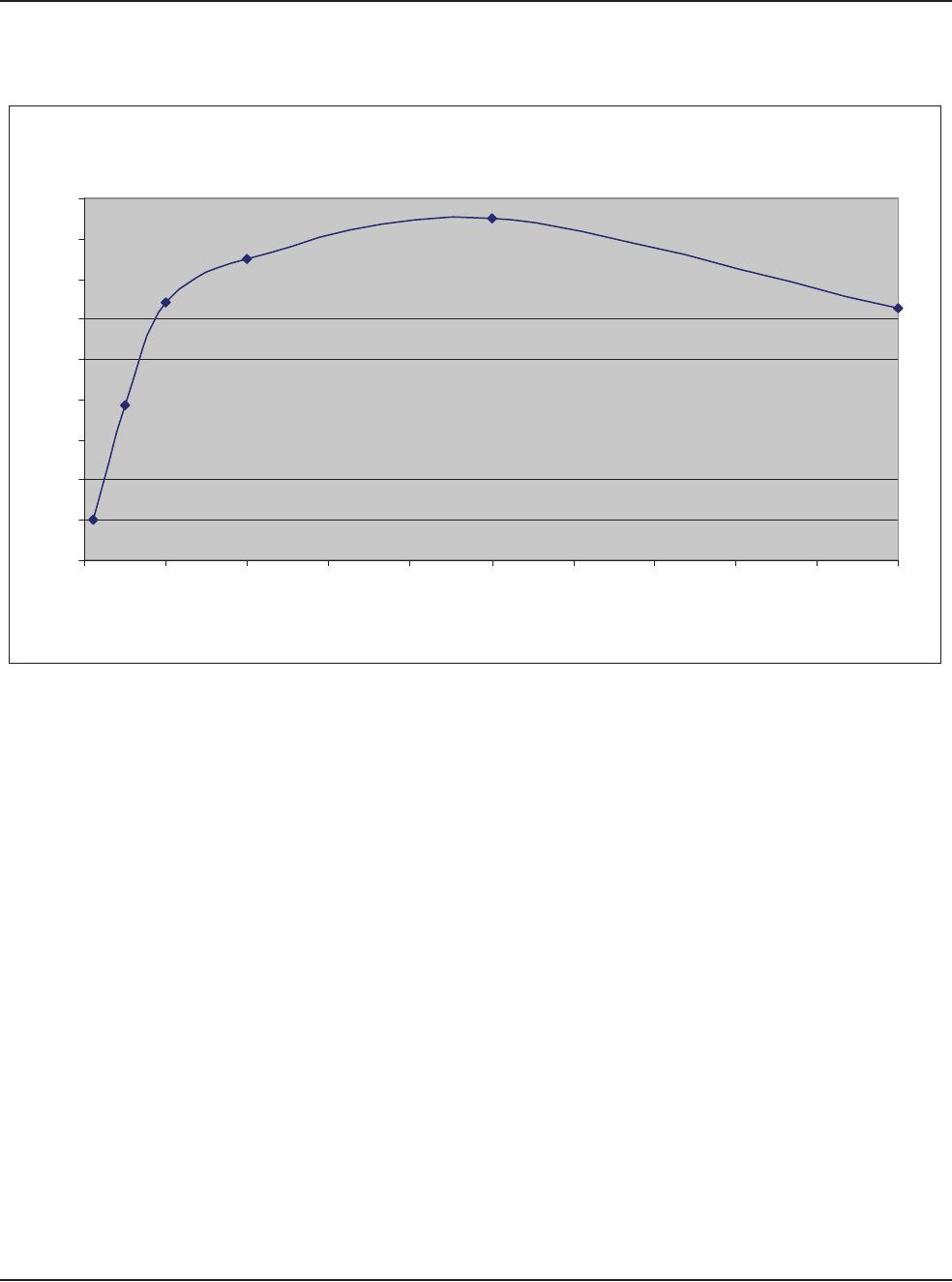
12 • Specifications
WHITESTAR SIGNATURE™ System Rx Only – Z370147 Rev. C 1008 12-11
Table 12.14 – Diathermy Output Power (100% Setting)
Diathermy Output Power (100% Setting)
0
1
2
3
4
5
6
7
8
9
0 100 200 300 400 500 600 700 800 900 1000
Load Resistance (Ohms)
Output Power (Watts) +/- 20%

12 • Specifications
WHITESTAR SIGNATURE™ System Rx Only – Z370147 Rev. C 1008 12-12
Table 12.15 – Diathermy Voltage
Diathermy Voltage
0
20
40
60
80
100
120
140
160
0 10 20 30 40 50 60 70 80 90 100
Control Panel Settings (%)
Output Voltage (Volts) +/- 20%
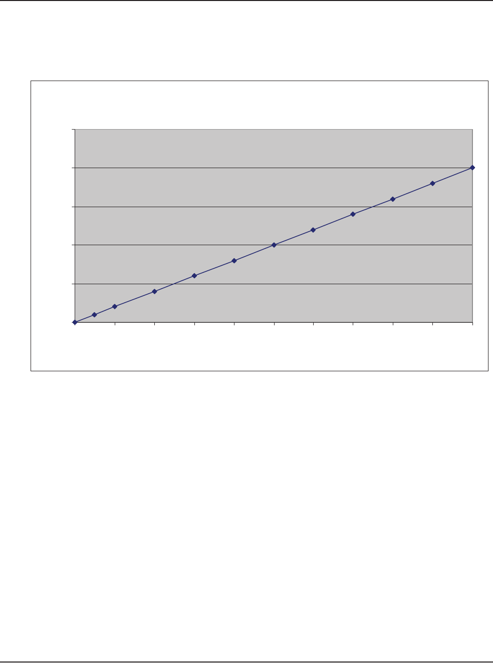
12 • Specifications
WHITESTAR SIGNATURE™ System Rx Only – Z370147 Rev. C 1008 12-13
Phaco Power
Graphs
Table 12.16 – Longitudinal Phaco Power
Phaco Power (Longitudinal)
0
5
10
15
20
25
0 10 20 30 40 50 60 70 80 90 100
Control Panel Settings (%)
Output Power (Watts) +/- 20%
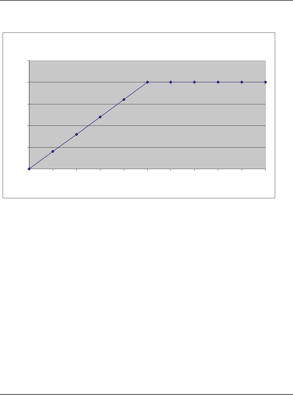
12 • Specifications
WHITESTAR SIGNATURE™ System Rx Only – Z370147 Rev. C 1008 12-14
Table 12.17 – Ellips™ Phaco Power Ellips
Phaco Power (Ellips™)
0
5
10
15
20
25
0 10 20 30 40 50 60 70 80 90 100
Control Panel Settings (%)
Output Power (Watts) +/- 20%
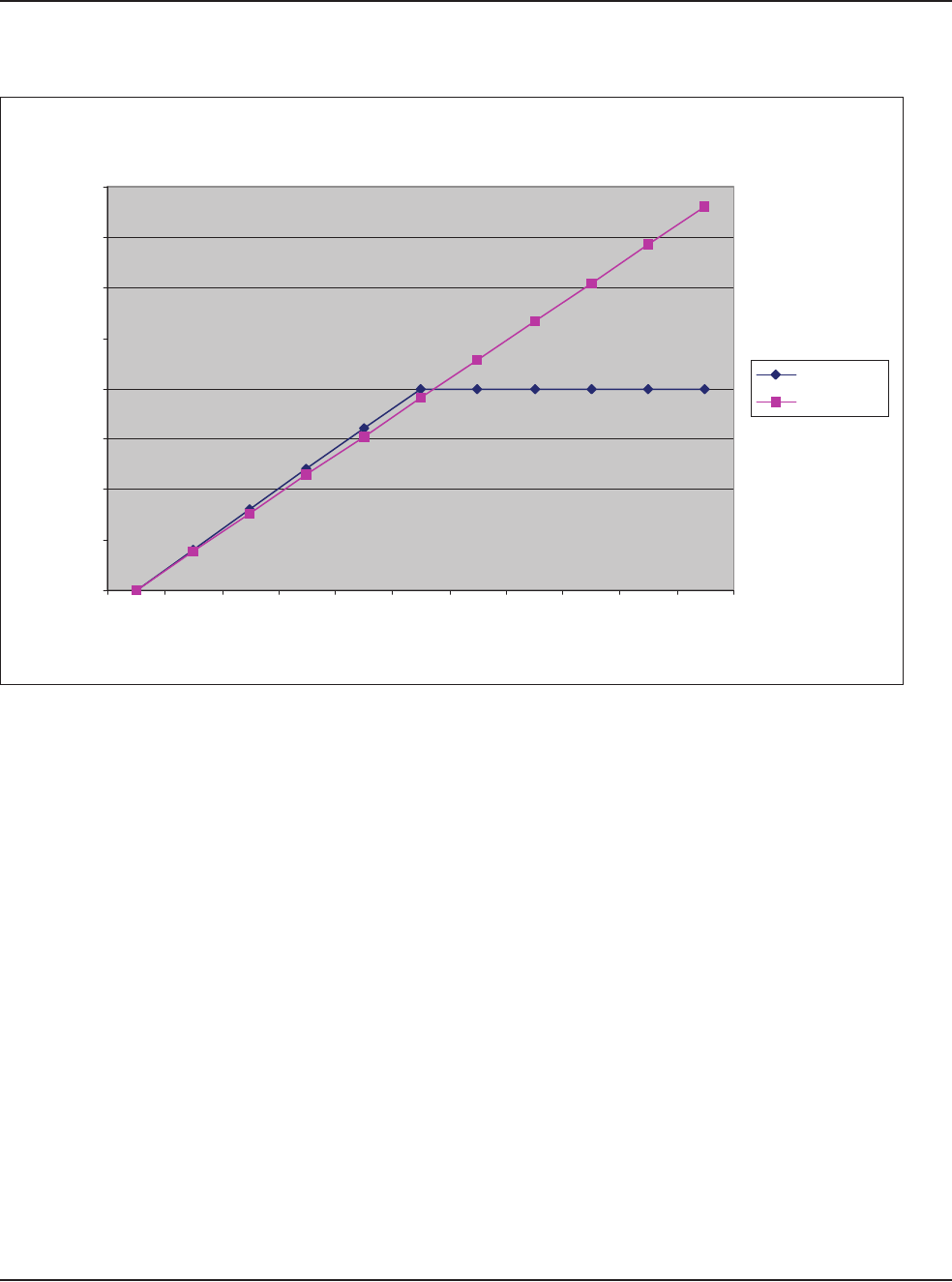
12 • Specifications
WHITESTAR SIGNATURE™ System Rx Only – Z370147 Rev. C 1008 12-15
Table 12.18 – Ellips™ and Longitudinal Phaco Power
Pow er Output (Watts)
0.00
5.00
10.00
15.00
20.00
25.00
30.00
35.00
40.00
0% 10% 20% 30% 40% 50% 60% 70% 80% 90% 100%
Displayed % Pow er
Watts
Ellips
Longitudinal
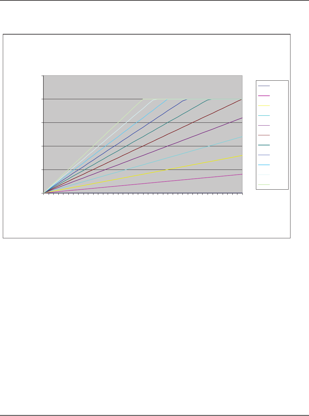
12 • Specifications
WHITESTAR SIGNATURE™ System Rx Only – Z370147 Rev. C 1008 12-16
Table 12.19 – Ellips™ Phaco Power Linear Mode
Ellips™ Power (in Linear Mode) Depending Upon User Defined
Max Power Setting
0.00
5.00
10.00
15.00
20.00
25.00
0.00%
10.00%
20.00%
30.00%
40.00%
50.00%
60.00%
70.00%
80.00%
90.00%
100.00%
Footpedal P3% Depression
Delivered Power (Watts)
0%
10%
20%
30%
40%
50%
60%
70%
80%
90%
100%

WHITESTAR SIGNATURE™ System Rx Only – Z370147 Rev. C 1008 13-1
List of Accessories with Part Numbers
13 ACCESSORIES AND PARTS
REORDERING

13 • Accessories and Parts Reordering
WHITESTAR SIGNATURE™ System Rx Only – Z370147 Rev. C 1008 13-2
Table 13.1 – WHITESTAR SIGNATURE™ System Part Number
List of Accessories
with Part Numbers
The following table is a list of accessories that you can use to reorder parts for your
WHITESTAR SIGNATURE™ System. Your AMO representative can advise you
of recommended inventory levels based on the volume of phacoemulsification
procedures done in your facility. All of the items listed below are ordered through
your AMO representative or directly through AMO Customer Service.
Table 13.2 – Accessories and Parts List
Name Description Part No.
WHITESTAR SIGNATURE™
Console
An ophthalmic microsurgical system. NGP680300
System Accessories Description Part No.
Phaco Handpiece AMO™ Phaco Handpiece SOV680290
WHITESTAR™ Phaco Handpiece,
Coaxial
690697
Ellips™ Phaco Handpiece 690858
19 Gauge LAMINAR™ Flow Phaco Tip,
0° Round Tip
OPOR0019L
19 Gauge LAMINAR™ Flow Phaco Tip,
15° Round Tip
OPOD1519L
19 Gauge LAMINAR™ Flow Phaco Tip,
30° Round Tip
OPOD3019L
19 Gauge LAMINAR™ Flow Phaco Tip,
45° Round Tip
OPOD4519L
Disposable 20 Gauge LAMINAR™
Flow Phaco Tip, 0° Round Tip
OPOD0020L
Disposable 20 Gauge LAMINAR™
Flow Phaco Tip, 15° Round Tip
OPOD1520L
Disposable 20 Gauge LAMINAR™
Flow Phaco Tip, 30° Round Tip
OPOD3020L
Disposable 20 Gauge LAMINAR™
Flow Phaco Tip, 45° Round Tip
OPOD4520L
Disposable LAMINAR™ Flow Phaco
Tip, 19 Gauge, 30° Curved
OPOCR3019L
Disposable LAMINAR™ Flow Phaco
Tip, 20 Gauge, 30° Curved
OPOCR3020L
19 Gauge LAMINAR™ Flow Irrigation
Sleeve and Test Chamber
OPOS19L
Disposable 20 Gauge LAMINAR™ Flow
Infusion Sleeve and Test Chamber
OPOD20L

13 • Accessories and Parts Reordering
WHITESTAR SIGNATURE™ System Rx Only – Z370147 Rev. C 1008 13-3
LAMINAR™ Flow Tip Wrench OPOMTWL
SOLO™ I/A Handpiece, 20 Ga., Curved
Silicone Sleeve Tip
OPOIA20CRV
SOLO™ I/A Handpiece, 20 Ga., 45°
Silicone Sleeve Tip
OPOIA2045D
SOLO™ I/A Handpiece, 20 Ga., Straight
Silicone Sleeve Tip
OPOIA20STR
SOLO™ I/A Handpiece Kit OPOIA20KIT
I/A Handpiece PHACOFIT™ Titanium Handle OM055002
PHACOFIT™ I/A Tip Curved .5 mm Port OM05510110
PHACOFIT™ O-Ring's I/A Tip (5PK) OM05510112
PHACOFIT™ Titanium, Multi-Tip Set OM05510113
PHACOFIT™ Cleaning/Flushing Kit OM05510114
PHACOFIT™ Tip, Luer Adapter
(Aspiration)
OM05510115
PHACOFIT™ Tip, 45 Degree Silicone
(No Sleeve)
OM05510116
PHACOFIT™ I/A Tip Straight .3MM
Port
OM0551011
PHACOFIT™ I/A Tip Curved .3 mm Port OM0551012
PHACOFIT™ I/A Tip 45 Degree 0.3 mm
Port
OM0551013
PHACOFIT™ I/A Tip 90 Degree 0.3 mm
Port
OM0551014
PHACOFIT™ I/A Tip Binkhorst 0.3 mm
Port
OM0551015
PHACOFIT™ I/A Tip Straight SI 0.3 mm
Port
OM0551016
PHACOFIT™ I/A Luer Adapter, F/F OM0551017
PHACOFIT™ I/A Tip Curved, SI, .3 mm
Port
OM0551018
PHACOFIT™ I/A Tip Straight .5MM
Port
OM0551019
PHACOFIT™ Athlete I/A Tip Straight
Type
OM0551020J
PHACOFIT™ Athlete I/A Tip 45 Degree
Type
OM0551021J
DUET™ STARTER KIT, 20GA DUA02020
System Accessories Description Part No.

13 • Accessories and Parts Reordering
WHITESTAR SIGNATURE™ System Rx Only – Z370147 Rev. C 1008 13-4
DUET™ ASPIRATION HANDLE DU02100
DUET™ IRRIGATION HANDLE DU02200
DUET™ 20G CURVED IRRIGATOR
CLOSED END
DU02301
DUET™ 20G CURVED ASPIRATION
.3MM PORT CAP POL
DU02302
DUET™ 19G FINE IRRIGATING
CHOPPER
DU02303
DUET™ 20G OLSON II IRRIGATING
CHOPPER
DU02305
DUET™ MST Aguirre Duet Tip DU02325
DUET™ MST Fine/Nagahara Tip DU02335
Diathermy Handpiece Bipolar Cord with Fischer Connection K106075
Bipolar Forceps, Curved Iris 0.5 mm Tip K121085
18 Gauge Straight Diathermy Pencil,
reusable
K147000
Vitrectomy Cutter 20 gauge Vitreous Cutter NGP0020
23 gauge Vitreous Cutter NGP0023
25 gauge Vitreous Cutter NGP0025
FUSION™ Tubing Pack Fusion™ Tubing Pack (disposable,
sterile)
OPO70
Fusion™ Dual Pump Tubing Pack
(disposable, sterile)
OPO71
Wireless Remote Control WHITESTAR SIGNATURE™ System
Remote Control
NGP680135
Footpedal WHITESTAR SIGNATURE™ Foot
Pedal (Single Linear)
NGP680701
Advanced Control Pedal for the
WHITESTAR SIGNATURE™
(Dual Linear)
NGP680702
Miscellaneous Power Cord, Hospital Grade, 20 ft., 6.1
meters
2410-0049-L
Footpedal Cable to WHITESTAR
SIGNATURE™ System
0100-0055
WHITESTAR SIGNATURE™ Dust
Cover
0100-0750
Sterilization Tray MSR309
WHITESTAR SIGNATURE™ System
Owner's Manual (English)
NGP Z370147
System Accessories Description Part No.

13 • Accessories and Parts Reordering
WHITESTAR SIGNATURE™ System Rx Only – Z370147 Rev. C 1008 13-5
WHITESTAR SIGNATURE™ System
Owner's Manual (Chinese)
NGP Z370161
WHITESTAR SIGNATURE™ System
Owner's Manual (Korean)
NGP Z370163
WHITESTAR SIGNATURE™ System
Owner's Manual (Japanese)
NGP Z370162
WHITESTAR SIGNATURE™ System
Owner's Manual (French)
NGP Z370148
WHITESTAR SIGNATURE™ System
Owner's Manual (German)
NGP Z370150
WHITESTAR SIGNATURE™ System
Owner's Manual (Swedish)
NGP Z370157
WHITESTAR SIGNATURE™ System
Owner's Manual (Finnish)
NGP Z370160
WHITESTAR SIGNATURE™ System
Owner's Manual (Portuguese)
NGP Z370152
WHITESTAR SIGNATURE™ System
Owner's Manual (Italian)
NGP Z370149
WHITESTAR SIGNATURE™ System
Owner's Manual (Spanish)
NGP Z370151
WHITESTAR SIGNATURE™ System
Owner's Manual (Danish)
NGP Z370158
WHITESTAR SIGNATURE™ System
Owner's Manual (Dutch)
NGP Z370153
WHITESTAR SIGNATURE™ System
Owner's Manual (Greek)
NGP Z370156
WHITESTAR SIGNATURE™ System
Owner's Manual (Norwegian)
NGP Z370159
WHITESTAR SIGNATURE™ System
Owner's Manual (Polish)
NGP Z370154
WHITESTAR SIGNATURE™ System
Owner's Manual (Russian)
NGP Z370155
WHITESTAR SIGNATURE™ System
Owner's Manual CD, Multilingual
NGP Z370164
System Accessories Description Part No.

WHITESTAR SIGNATURE™ System Rx Only – Z370147 Rev. C 1008 Glossary-1
GLOSSARY
Term Definition
Active Reflux Reflux that occurs in response to a user request (typically by way of
the footpedal).
Active State The state where the instrument responds to the footpedal in all zones.
All the surgical modes are operative.
Active Vacuum Vent The vacuum is relieved by a controlled reversal of the peristaltic
pump or by the vacuum regulator.
Advanced Control Pedal (Dual
Linear)
A footpedal for the WHITESTAR SIGNATURE™
Phacoemulsification System that operates in two independent linear
movement planes (Pitch and Yaw). The two linear movement planes
provide proportional control of user-defined functions.
Anterior Chamber A fluid filled space inside the eye between the iris and the innermost
corneal surface.
Anterior Mode The Anterior function operating mode of the instrument.
Anterior Segment The front third of the globe; includes structures located between the
front surface of the cornea and the vitreous.
Aspiration Removal of fluid from the eye using the pumps.
Aspiration Line Fluids pathway within he handpiece that is utilized to extract fluid and
tissue from the eye.
Burst Mode One of the available options on the WHITESTAR SIGNATURE™
System for phaco power delivery. Characterized by short periods of
time where the power is turned on, interspersed with off times.
CASE ChAmber Stabilization Environment is an intelligent vacuum system
that monitors occlusions and adjusts the vacuum to prevent or reduce
post occlusion surge or chamber collapse.
Cassette The tubing packs that are installed on the system to connect the tubing
on the hand pieces to the vacuum and irrigation sources in the
instrument.
Compatible Surgeon Programs Programs that have the same Pack Type, Pump Type, and Infusion
method.
Continuous Phaco Power One of the available Phaco power delivery modes.

Glossary
WHITESTAR SIGNATURE™ System Rx Only – Z370147 Rev. C 1008 Glossary-2
Controller A processor or microcontroller that is programmed to fulfill a specific
task. It can be anything from a small 8-bit microprocessor to a PC-
compatible system. On the WHITESTAR SIGNATURE™ system,
the following controllers have been identified: GUI Host Processor,
Instrument Host Processor, Fluidics Controller, Phaco-Diathermy
(PD) Controller, Pneumatic Controller, Diagnostic Controller, IV
Pole Controller, Remote Controller, Touch Screen Controller,
Footpedal Controller, Footpedal Wireless Controller, Remote
Wireless Controller, and Sound Controller.
Continuous Burst Phaco Power One of the available Phaco power delivery modes.
Diathermy Method used to coagulate blood vessels during a cataract procedure
and to join together the conjunctiva at the end of a cataract procedure
using electrical current.
DLL Dynamic Link Library. A collection of software routines that can be
loaded and accessed at run time.
Ellips™ Technology A technology that provides both longitudinal and transverse
movement within the Ellips™ handpiece.
EMI Electromagnetic Interference. Emitted by electrical circuits carrying
rapidly changing signals, as a by-product of their normal operation,
and which causes unwanted signals (interference or noise) to be
induced in other circuits.
Evacuation The removal, by suction, of fluids from the eye cavity through a
phacoemulsification ultrasonic handpiece.
Extraction The process or act of pulling or drawing out fluids from the eye cavity
during Phacoemulsification surgery.
Fluidics The components and aspects of the system involving fluid;
specifically, irrigation, aspiration, vacuum, pressure and their
performance as interdependent systems.
FPn Foot Pedal zone position (0, 1, 2, or 3). The zone changes when the
footpedal is pressed.
FUSION™ The screen in which the Occlusion mode, CASE mode, and Actual
Maximum Vacuum settings can be modified.
FUSION™ Fluidics Pack
(OPO70)
The fluidic tubing pack which interfaces only with the peristaltic
pump related components.
FUSION™ Dual Pump Pack
(OPO71)
The FUSION™ dual pump fluidic tubing pack which interfaces with
both the peristaltic and the vacuum-based pump related components.
Gravity Infusion The bottle height-induced irrigation when the IV pole is positioned at
a specific height.
GUI Graphical User Interface. Used to reference the interface presented to
the user on a graphical screen.
High Power Pulse Phaco Power One of the available Phaco power delivery modes.
Term Definition

Glossary
WHITESTAR SIGNATURE™ System Rx Only – Z370147 Rev. C 1008 Glossary-3
IV Pole The programmable pole used to position the irrigation solution during
the phacoemulsification process.
I/A A general term for Irrigation/Aspiration, and a specific footpedal
configuration.
IAC A Vitrectomy mode that uses the Irrigation, Aspiration, and Cutting
sequences as the footpedal is pressed.
ICA A Vitrectomy mode that uses the Irrigation, Cutting, and Aspiration
sequences as the footpedal is pressed.
Irrigation Causing fluid to be moved into/toward the eye via the irrigation line.
Irrigation Line The fluid path within the handpiece that is used to allow the clean
balanced salt solution to travel from the bottle into the eye.
LCD The Liquid Crystal Display on the WHITESTAR SIGNATURE™
System.
Linear Variable Any switch on the footpedal that is used for Linear control. (Pitch or
Yaw.)
Long Pulse Phaco Power One of the available Phaco power delivery modes.
Low Power Pulse Phaco Power One of the available Phaco power delivery modes.
Max Vac (Maximum Vacuum) The value for a vacuum based fluidic is the lesser of 600 mmHg or
85% of the CASE Upper Threshold. The maximum value for a
peristaltic pump is 650 mmHg.
Motor Venting Used with both the FUSION™ Fluidics pack (OPO70) and the Dual
Linear (OPO71) pack. Driving the peristaltic pump in the reverse
direction to vent.
Multiple Burst Phaco Power One of the available Phaco power delivery modes.
NiMh Nickel-Metal Hydride. A type of rechargeable battery.
One-Touch CASE The ability to alter the CASE settings with a single press of a button.
The modes are +2, +1, Standard, -1, -2.
Operating Mode The current operating mode of the instrument. The modes are Phaco,
I/A, Vitrectomy, and Diathermy.
Pairing The process of matching two BlueTooth Devices, the console and the
remote control or the console and the wireless foot pedal, so that they
can communicate with one another.
Pars Plana Incision A surgical cut into the eyeball that passes through the sclera and the
pars plana area of the cilary body, between the pars plans and the ora
serrata. Common site for instruments used for Vitrectomy procedures.
Passive Reflux A small reflux from the aspiration line that occurs automatically when
the system vents. Historically, this has occurred on AMO systems that
utilize valve venting.
Peristaltic A flow based pump.
Term Definition

Glossary
WHITESTAR SIGNATURE™ System Rx Only – Z370147 Rev. C 1008 Glossary-4
Phacoemulsification / Phaco The term is abbreviated as Phaco. Phaco is a cataract extraction
technique originally developed by Dr. Charles Kelman. To use this
technique, a surgeon makes a small incision in the eye and emulsifies
the cataract with the help of a vibrating needle inserted through the
incision. The emulsified particles of the cataract are gently aspirated
through the needle while the surgeon continues to irrigate the eye's
chamber to maintain intraocular pressure (IOP).
Pitch The vertical travel of the footpedal.
Pneumatics Components and aspects of the system involving high and low
pressure and vacuum.
Post Occlusion Surge A result of rapidly changing pressures within the anterior chamber of
the eye. The fluid surge is caused when the Phaco Tip is blocked
during a procedure and is suddenly cleared. The surge can cause an
imbalance of fluids leaving the eye and potential damage to the eye
tissue.
Power Boost Mode An operating mode in which the yaw movement of the Advanced
Control Pedal (Dual Linear Footpedal) is utilized to provide a
temporary increase (Boost) in phaco power.
Primary Venting Mechanism A venting mechanism (valve, motor) selected by the host software as
the preferred means of performing venting.
Programming Mode (System
Configuration)
When the system is not Primed/and not Tuned Phaco, I/A, and
Vitrectomy surgical modes are not available. However, the user can
program and update surgical and system settings.
Pump Ramp A characteristic of the peristaltic pump that determines the point at
which the pump speed is decreased in order to maintain a manageable
rate of vacuum rise.
Pulse Shape A feature of WHITESTAR® Technology which allows the user to
define a "kick" of increased power at the beginning of a
WHITESTAR® pulse over a range of Phaco power settings.
Reflux Fluid that is moved into/toward the eye via the aspiration port/line.
The reverse flow within the aspiration line that can be used to release
or dislodge unwanted material from the handpiece tip or to “tent” the
incision site to allow easier tip insertion. Reflux is not intended to
clear a clogged handpiece. However, reflux can be used to identify a
blockage.
Remote Control A user interface control for the GUI system through a wireless
connection. The Remote Control commands are interpreted to control
the GUI software.
Safe State A state where the Phaco, Vitrectomy, Diathermy, and fluidics
functions are disabled, with irrigation on and the fluid vented. The
instrument the footpedal is disabled. As a result, all of the surgical
modes become inoperable.
Term Definition

Glossary
WHITESTAR SIGNATURE™ System Rx Only – Z370147 Rev. C 1008 Glossary-5
Secondary Venting Mechanism A venting mechanism (valve, motor or vacuum regulator)
automatically used by the system to attempt venting if the primary
venting mechanism should fail.
Short Pulse Phaco Power One of the available Phaco power delivery modes.
Single Burst Phaco Power One of the available Phaco power delivery modes.
Single Linear Footpedal A footpedal with only one plane of travel allowing proportional
control of system parameters.
SubMode A submode is a defined set of parameters for the current mode. Most
operating modes have multiple submodes. For example, there are
three I/A submodes for Anterior surgery, each of which contains a set
of potentially different parameters for the I/A mode.
Surgical Media Center (SMC) An optional accessory product that can be connected to the
WHITESTAR SIGNATURE™ system to generate and record video
images of the surgery. The video images contain embedded
information about the instrument status and settings throughout the
surgical procedure.
System A hardware unit and associated peripherals including software
required to perform a specific function.
Tenting the Incision (Wound) Using reflux while inserting the handpiece into the eye. This
technique causes the incision (wound) to open slightly (tent), thus
making handpiece insertion easier.
Touch Screen The display surface of the Liquid Crystal Display (LCD) that
responds to touch.
Vacuum Boost Mode An operating mode in which the yaw movement of the Dual Linear
Footpedal is utilized to provide a temporary increase (Boost) in the
maximum vacuum.
Vacuum Regulator Venting Using the vacuum regulator in the WHITESTAR SIGNATURE™
system to vent the vacuum in the OPO71 vacuum tank. Used only
with the Venturi pump.
Valve Reflux The fluid flows back through the pinch valve.
Valve Vent The vacuum is vented through the aspiration line.
Valve Venting Used with OPO70 pack only. Manipulation of the fluidic connections
to cause fluid from the irrigation bottle to be directed toward the
aspiration port in order to vent. Typically this results in passive reflux.
Variable WS A mode where the user can define the WHITESTAR® Technology
delivery based on the footpedal position.
Venting Relieving vacuum in the aspiration tube. Typically venting is
performed when the Footpedal is moved from position 2 into position
1 or 0.
Venturi A vacuum based pump.
Term Definition

Glossary
WHITESTAR SIGNATURE™ System Rx Only – Z370147 Rev. C 1008 Glossary-6
Vitrectomy The removal of vitreous with a needle-like cutter that has fluid
injection and suction capabilities.
WHITESTAR® Technology A proprietary software technology that is used to deliver finely
modulated pulses of energy, interrupted by extremely brief cooling
periods.
Yaw The horizontal movement of the footpedal that works from either the
left or the right of the footpedal.
Yaw Threshold The programmed yaw movement that is allowed before the yaw
switch is activated on the footpedal.
Term Definition

WHITESTAR SIGNATURE™ System Rx Only – Z370147 Rev. C 1008 Index-1
A
Accessories 13-1
Add a Surgeon 6-3
Adjusting
Cut Rates 5-30
Flow Rate 5-29
Advanced Control Pedal
Does Not Pair 10-18
Dual Linear 1-4, 3-11, 3-22, 7-4, 9-5, 12-2
Modes
Vitrectomy 5-21
Pitch
Thresholds 5-32
VIT 5-33
Settings
Dual Linear 5-20
Wireless 3-22
Anterior chamber too deep 10-19
Anterior Segment
Settings 5-38
Surgery 3-15
Anterior Segment Surgery 5-1
Aspiration
Specifications 12-3
Troubleshooting 10-20
Aspiration Flow Rate 5-29
Aspiration Rate
Occlusion 5-46
PHACO 5-7
Vitrectomy 5-18
Assign Order 6-14
Autoclave 9-4
B
Backlight button 10-17
Balance
Irrigation/Aspiration 4-10
balanced salt solution 3-19
batteries
footpedal 3-22, 9-5
remote control 3-26
Battery
Location
Wireless Foot Pedal 10-4
Replacement
Wireless Foot Pedal 10-3
Begin Tune 4-9
blocked
aspiration port 5-49
Bluetooth™ 10-17
Bluetooth™ devices 10-18
Bottle Height
IA 5-26
PHACO 5-27
Vitrectomy 5-28
Burst 5-3
Bypass 4-7, 4-11
INDEX

Index
WHITESTAR SIGNATURE™ System Rx Only – Z370147 Rev. C 1008 Index-2
C
Calibration
Touch Screen 7-7
Wireless Foot Pedal 7-5
Care of the System 9-5
CASE 5-7
CASE Lower Threshold
PHACO 5-27
CASE Mode 5-42
PHACO 5-27
CASE ONE Touch 1-7, 5-44
CASE Upper Threshold
PHACO 5-27
CASE Vac
PHACO 5-27
CASE Vacuum 5-17
Cassette
Loading 3-18
Chamber partially collapses 10-20
Changing
Irrigation 3-3
Mode Parameters 4-12
charging the footpedal 9-5
Check-out 8-2
Irrigation/Aspiration 8-2
Phacoemulsification 8-2
Vitrectomy 8-3
Cleaning
Handpiece 9-2
System 9-5
Common Problems 10-5
Complete
Setup 3-19
Components 2-2
Configuration 4-12
Connecting Handpieces 3-3
Connections
Rear Panel 3-16
Console Dimensions 12-2
Continuous Burst 5-38
PHACO Power 5-41
Continuous Irrigation 1-5, 4-7, 5-6
Cup Fill 4-9
IA 5-26
PHACO 5-27
Continuous Phaco Power 5-39
Continuous Power 5-38
Controls
Screens 4-2
Copy a Program 6-10
Cup Fill 4-7, 4-9
Custom Duty Cycles 5-12
Cut Rate
Adjusting 5-30
Vitrectomy 5-18, 5-28
cuts per minute 5-30
Cutter
Vitrectomy 3-21
Cutting Rates
Vitrectomy 5-30
D
Database 4-2
Delete 6-13
Management 7-2
Program 6-14
Restore 6-13
Default Program 4-6, 5-22
Default Settings
Diathermy 5-25
Footpedal 5-24
Irrigation/Aspiration 5-26
PHACO 5-27
Sound 5-23
Vitrectomy 5-28
Delete
Database 6-13
Program 6-12, 6-13
Surgeon 6-11
DIA time 5-3
Diagnostics 4-2, 7-2, 10-1

Index
WHITESTAR SIGNATURE™ System Rx Only – Z370147 Rev. C 1008 Index-3
Diathermy 1-6, 3-4, 5-2
Default Settings 5-25
Forceps 3-21
Handpiece 9-3
Part Numbers 13-4
Output Power 12-10
Pencil Probe 3-21
Power 12-10
Power Graphs 12-5
Specifications 12-3
Troubleshooting 10-21
Using 5-3
Voltage 12-12
Dimensions 12-2
drainage bag 3-18
DT 5-3
Dual Linear
Advanced Control Pedal 1-4, 3-11, 3-22,
5-32, 7-4, 9-5, 12-2
Settings 5-20
Settings
Advanced Control Pedal 5-20
VIT Footpedal Settings 5-33
Dual Linear Foot Pedal does not pair 10-18
Dual Pump 1-5
Duty Cycles 5-10
PHACO 5-28
E
Edit
Program 6-9
Surgeon 6-5
Effective Phaco Time 5-36
Electrical
Specifications 12-3
Ellips™ 1-4
Handpiece 1-4, 3-17
Technology 5-49
End Case 4-2, 5-35
Environmental
Specifications 12-3
EPT 5-36
Equipment Operation 4-1
Error Message 10-2
Error Messages 10-5
F
failed to pair 10-17
Feedback
Footpedal 5-25
Flash Sterilization 9-4
Flow Rate
Adjusting 5-29
Fluidics 1-4
Error Messages 10-5
Mode
PHACO 5-27
Foot Pedal
Battery Replacement 10-3
Calibration 7-5
Pitch
Advanced Control Pedal 5-32
Pitch Thresholds
single linear 5-31
Settings
single linear 5-20
Single Linear 1-4
wireless 3-4
Footpedal 1-4, 3-22, 4-2
Advanced Control Pedal 3-11
charging 9-5
Dual Linear
Advanced Control 3-11
Feedback 5-25
Modes
Vitrectomy 5-21
Part Number 13-4
Pitch 3-23
Pitch Regions 5-25
Positions 3-23, 5-12
Settings 5-24, 5-31
Setup
Wireless 7-3
Single Linear 3-22
Specifications 12-2

Index
WHITESTAR SIGNATURE™ System Rx Only – Z370147 Rev. C 1008 Index-4
Summary
single linear 5-24
Switch Assignment 5-33
Threshold 5-25
Vitrectomy 5-18, 5-28
Wireless 1-4, 3-22
Forceps 11-2
Diathermy 3-21
Fuse
Location 10-3
Replacement 10-2
Fusion 5-17, 5-45
FUSION™ 2-4
FUSION™ Tubing Pack
Part Number 13-4
G
Gas Sterilization 5-29, 9-4
General
Troubleshooting 10-16
Graph
Phaco Power 12-13
Graphic User Interface 1-5
Graphs
Diathermy Power 12-5
Gravity Displacement Sterilization 9-4
GUI 1-5
H
Handpiece
Cleaning 9-2, 9-3
Connecting 3-3
IA 3-18
Phaco 3-20
Priming 4-8
Ultrasonic 3-3
Warranty 11-2
Help 10-2
High Power
Limit 5-15
Pulse 5-38
PHACO Power 5-40
I
IA
Handpiece 3-18
Submodes 5-5
IAC 5-21
ICA 5-21
ICE Pulse Shaping
WHITESTAR® 5-15
Infusion Sleeve 2-4
Initial Mode 5-8, 5-25, 5-26, 5-29
Inspection Instructions 2-2
Install Tubing Cassette 4-6
Irrigation
Changing 3-3
Continuous 4-7, 5-6
flow does not stop 10-19
Inadequate 3-3
Specifications 12-3
Troubleshooting 10-19
Irrigation/Aspiration 1-7, 5-4
Balance 4-10
Check-out 8-2
Default Settings 5-26
IV Pole
does not work 10-18
Programmable 3-4, 3-25, 5-4
K
kick 5-15
L
LAMINAR™ Flow 3-18
Linear 5-2, 5-3, 5-29
Occluded Power 5-48
List of Accessories 13-1
Load
Impedance 12-10
Resistance 12-10
Locked Program 6-13
Logs 7-2

Index
WHITESTAR SIGNATURE™ System Rx Only – Z370147 Rev. C 1008 Index-5
Long Pulse
PHACO Power 5-39
Power 5-38
Rate
PHACO 5-27
Low batteries 10-17, 10-18
Low Power
Limit 5-15
Pulse 5-38
PHACO Power 5-40
Lower Threshold 5-17
M
Maintenance 4-2, 11-2
Touch Screen 7-7
Max Aspiration
IA 5-26
Rate
Occluded
PHACO 5-28
PHACO 5-27
Vitrectomy 5-28
Max Phaco Power
Occluded
PHACO 5-28
Unoccluded
PHACO 5-28
Max Power
Diathermy 5-25
Max Vacuum 5-9
IA 5-26
PHACO 5-27
Vitrectomy 5-28
maximum vacuum 5-16
Mayo Stand Drape 2-4
Messages
Error 10-2
Miscellaneous Part Numbers 13-4
Mode Programming 1-6
Modes
Changing Parameters 4-12
How to program 5-22
Monitor Drape 2-4
Multiple Burst
PHACO Power 5-40
Power 5-38
Multiple Mode Programming 1-6
N
NiMH 3-22, 10-3
No aspiration 10-20
No diathermy or poor diathermy 10-21
No irrigation flow 10-19
No phacoemulsification 10-21
No sound when using diathermy 10-21
No vacuum 10-20
No vitrectomy cutting 10-22
O
Occluded Aspiration Rate 5-45
Occluded Phaco 5-7
Occlusion
Aspiration Rate 5-46
Threshold 5-9
PHACO 5-27
Vacuum Threshold 5-46
Venting 5-49
OCCLUSION MODE™ Phaco
Settings 5-27, 5-42, 5-45
Off Time 5-28
On Time 5-28
ONE Touch
CASE 5-44
Operating Modes 1-6
Anterior Segment 5-1
Operating the Equipment 4-1
Output Power
Diathermy 12-10
Override Settings 5-41

Index
WHITESTAR SIGNATURE™ System Rx Only – Z370147 Rev. C 1008 Index-6
P
pair
Advanced Control Pedal 10-18
Dual Linear Foot Pedal 10-18
Wireless Remote Control 10-17
Pairing Instruction
Wireless Remote Control 7-6
Pairing Instructions
Wireless Foot Pedal 7-4
Panel 5-2, 5-3, 5-29
Occluded Power 5-48
Parameter Settings
WHITESTAR® Technology 5-11
Parameters
Programming 1-6
Part Numbers 13-2
Parts
Reordering 13-1
Passive Reflux 5-49
Pencil Probe
Diathermy 3-21
Percent Kick
High End of Range 5-15
Low End of Range 5-15
Peristaltic Pump 12-3
PHACO
Default Settings 5-27
Program 5-8
Submodes 5-7
Using 5-8
Phaco Handpiece 1-4, 3-4, 3-17, 3-20, 9-2
Part Numbers 13-2
PHACO Power 5-38
Phaco Power 5-7
Continuous 5-39
Graph 12-13
Phacoemulsification 1-2, 1-7, 3-3, 3-16, 5-6, 5-7,
8-3, 10-21, 12-4
Check-out 8-2
Specifications 12-4
Troubleshooting 10-21
Physical Specifications 12-2
PITCH 3-23
Pitch Regions
Footpedal 5-25
Poor aspiration 10-20
Poor phacoemulsification 10-21
Positions
Footpedal 3-23
Power
Continuous 5-38
Continuous Burst 5-38
Delivery
Diathermy 5-25
PHACO 5-27, 5-28
Failure 3-3
High Pulse 5-38
Long Pulse 5-38
Low Pulse 5-38
Multiple Burst 5-38
PHACO 5-7
Phaco 5-38
Short Pulse 5-38
Single Burst 5-38
Switch 10-5
Power Cord Length 12-2
pps 5-39
Precautions 8-2
Safety 3-2
Preferred Program 6-6
Prevacuum Sterilization 9-4
Prime
Bypass 4-7
Prime/Tune 1-5, 4-2, 4-7, 4-8, 4-9, 5-3, 8-2
Priming
Handpiece 4-8
Vitrectomy 4-11
Problems
Common 10-5

Index
WHITESTAR SIGNATURE™ System Rx Only – Z370147 Rev. C 1008 Index-7
Program 4-2
Assign Order 6-14
Configuration 5-22
Database 6-14
Defaults 5-22
Delete 6-12
Edit 6-9
Lock 6-13
Locked 6-13
Preferred 6-6
Programmable IV Pole 1-6, 3-4, 3-19, 3-25, 5-4
Specifications 12-2
Programming
Multiple Mode 1-6
PHACO 5-8
Programs
Select 4-4
Surgeon 6-1
Pulse Off Time 5-11
Pulse On time 5-11
Pulse Rate 5-11
Pulse Shaping 5-13
pulses per second 5-39
Pump not working 10-20
Pump Ramp
PHACO 5-27
Threshold
IA 5-26
R
Rear Panel 3-16
Recording Mode 3-29
Reduced/insufficient irrigation flow 10-19
Reflux 3-24
Passive 5-49
Remote Control 3-4
Wireless 3-26, 7-6
Remote Pair 7-6
Reordering
Parts 13-1
Replacing
Batteries 10-2, 10-3
Replacing the Fuse 10-2
Reset
Timers 4-10
Restore
Database 6-13
Restriction of Hazardous Substances 3-14
RoHS 3-14
S
Safety Precautions 3-2
Screens
Controls 4-2
Select Program 4-6
Selecting a Language 4-3
Self Test 4-4
Settings
Anterior Segment 5-38
Footpedal 5-31
How to program 5-22
Occlusion Mode 5-45, 5-48
OCCLUSION MODE™ Phaco 5-42
Override 5-41
Submode Parameters 5-4
Setup
Completion 3-19
Sequence 3-15
System 8-2
Wireless 7-6
Short Pulse
PHACO Power 5-39
Power 5-38
Rate
PHACO 5-27
Shutdown
Sequence 3-30
Side VIT 5-21
Side vitrectomy 5-21
Single Burst
PHACO Power 5-40
Power 5-38
Single Linear
Foot Pedal 1-4, 12-2
Settings 5-20
Pitch Thresholds 5-31

Index
WHITESTAR SIGNATURE™ System Rx Only – Z370147 Rev. C 1008 Index-8
Sleep Mode 10-17
SMC
Surgical Media Center 3-28
SOLO™ 3-18
Sounds 4-2
Default Settings 5-23
Specifications
Diathermy 12-3
Electrical 12-3
Environmental 12-3
Footpedal 12-2
Fuse 10-2
IA 12-3
IV Pole 12-2
Phacoemulsification 12-4
Physical 12-2
Vitrectomy 12-4
Start Vit Prime 8-3
Startup 4-4
Status 10-5
STD Surgeon 6-2
Sterilization 3-22, 9-4
Gas 9-4
Gravity Displacement 9-4
Prevacuum 9-4
Storage Conditions 12-3
Submode
Parameters 5-4
PHACO 5-7, 5-41
Submodes
IA 5-5
PHACO 5-7
Surgeon
Add 6-3
Copy 6-10
Delete 6-11
Edit 6-5
Select 6-1
STD 6-2
Surgeon/Program
Select 4-4
Surgeons and Programs 4-13
Surgical Media Center
SMC 3-28
Switch Assignment 5-31
Footpedal 5-33
Symbol Definitions 3-9
System
Check-out 8-2
Cleaning 9-5
Console 1-5
Default Settings 5-23
Description 1-2
Disposal 3-12
does not turn on 10-16
Self Test 4-4
Shutdown 3-30
Tests 7-2
Utilities 7-2
T
Technical Service 10-5
Technology
WHITESTAR® 5-9
Test Chamber 2-4, 13-2
Threshold
Vacuum 5-46
Timers
Reset 4-10
Touch Screen
Calibration 7-7
Does not respond 10-18
Using 4-12
Translucency 3-28
Troubleshooting 8-2, 10-1
Aspiration 10-20
Diathermy 10-21
General 10-16
Irrigation 10-19
Phacoemulsification 10-21
Vitrectomy 10-22
Tubing Cassette 2-4
Install 3-18, 4-6
Tune 4-7
Begin 4-9

Index
WHITESTAR SIGNATURE™ System Rx Only – Z370147 Rev. C 1008 Index-9
U
Ultrasonic (U/S) Time 5-36
Ultrasonic Handpiece 3-3
Unoccluded Phaco 5-7
Unpair 10-17
Up Time
PHACO 5-27
Threshold 5-17
Upper Threshold 5-17
Using
Diathermy 5-3
PHACO 5-8
too much fluid 10-19
Touch Screen 4-12
Vitrectomy 5-19
V
Vacuum 5-35
monitoring 5-16
PHACO 5-7
pressure 5-49
Rate
Linear 5-29
Panel 5-29
Vitrectomy 5-18
Variable WHITESTAR® Technology 5-12
Variable WS 5-12
Venting
Occlusion 5-49
Venturi pump 5-17
VIT Foot Pedal Settings
dual linear 5-33
Vitrectomy 3-4, 3-21, 5-18
Advanced Control Pedal (Dual Linear) Modes
5-21
Check-out 8-3
Cut Rate 5-30
Cutter 3-4
Default Settings 5-28
Footpedal Modes 5-21
Prime 4-11
Specifications 12-4
Troubleshooting 10-22
Using 5-19
VIT 1-7
Voltage
Diathermy 12-12
W
Wake-up 3-24
Warnings 3-2, 3-5
Warranty 11-1
Watts 12-5, 12-14
WHITESTAR
Decrement 5-33
Increment 5-33
WHITESTAR® ICE Technology 1-3
WHITESTAR® Technology 1-3, 5-9
Wireless Advanced Control Pedal 3-22
Wireless Foot Pedal 3-4
Battery Location 10-4
Calibration 7-5
Wireless Footpedal
Pairing 7-4
Setup 7-3
Wireless Remote Control 1-5, 3-4, 3-26
Part Number 13-4
Setup 7-6
wireless remote control does not pair 10-17
Y
Yaw 3-23