Johnson and Johnson Surgical Vision SIGACPM2 Advanced Control Pedal Master User Manual User s Manual 1
Abbott Medical Optics Advanced Control Pedal Master User s Manual 1
Contents
- 1. User manual 1
- 2. User Manual 2
User manual 1
WHITESTAR SIGNATURE ™
OWNER’S AND
OPERATOR’S MANUAL
Manufactured By:
Advanced Medical Optics, Inc.
1700 E. St. Andrew Place
Santa Ana, CA 92705
USA
1-800-449-3060
www.amo-inc.com
For Order Placement
of Surgical Products
(IOLs and Phaco Supplies)
Call 1-877-AMO-4LIFE (USA)
1-877-266-4543
For Phaco Returns or Technical
Service
Call 1-877-AMO-4LIFE (USA)
1-877-266-4543
All returns must be accompanied by a
RGA#
(Returned Goods Authorization)
EC REP
AMO Ireland
Block B
Liffey Valley Office Campus
Quarryvale Co., Dublin Ireland
Rx Only – Z370147 Rev C 1008
© 2008 Advanced Medical Optics, Inc.
Trademarks
AMO, the AMO ADVANCED MEDICAL OPTICS logo and WHITESTAR are registered
trademarks. ELLIPS, FUSION, LAMINAR, PHACOFIT, OCCLUSION MODE, and
WHITESTAR SIGNATURE are trademarks of Advanced Medical Optics, Inc.
DUET and SOLO are trademarks of Micro-Surgical Technology, Inc.
The Bluetooth word mark, figure mark (stylized “B Design”), and combination mark (Bluetooth
word mark and “B Design”) are registered trademarks of the Bluetooth SIG.
All brand names and products and company names mentioned in this document are the trade name,
service mark, or registered trademarks of their respective owners.
Compliance
In accordance with:
• IEC/EN 60601-1

Table of Contents
WHITESTAR SIGNATURE™ System Rx Only – Z370147 Rev. C 1008 i
TABLE OF CONTENTS
Introduction . . . . . . . . . . . . . . . . . . . . . . . . . . . . . . . . . . . . . . . . . . . . . . . . . . . . . . . . . . . . 1-1
About this Manual . . . . . . . . . . . . . . . . . . . . . . . . . . . . . . . . . . . . . . . . . . . . . . . . . . . . . . . . 1-2
About Phacoemulsification. . . . . . . . . . . . . . . . . . . . . . . . . . . . . . . . . . . . . . . . . . . . . . . . . . 1-2
Intended Use . . . . . . . . . . . . . . . . . . . . . . . . . . . . . . . . . . . . . . . . . . . . . . . . . . . . . . . . . . . . . 1-2
WHITESTAR SIGNATURE™ System Description & Features. . . . . . . . . . . . . . . . . . . . . 1-2
WHITESTAR® Technology . . . . . . . . . . . . . . . . . . . . . . . . . . . . . . . . . . . . . . . . . . . . . . . . 1-3
FUSION™ Fluidics System . . . . . . . . . . . . . . . . . . . . . . . . . . . . . . . . . . . . . . . . . . . . . . . . . 1-4
Accessories . . . . . . . . . . . . . . . . . . . . . . . . . . . . . . . . . . . . . . . . . . . . . . . . . . . . . . . . . . . . . . 1-4
WHITESTAR SIGNATURE™ System Console. . . . . . . . . . . . . . . . . . . . . . . . . . . . . . . . . 1-5
WHITESTAR SIGNATURE™ System Operating Modes . . . . . . . . . . . . . . . . . . . . . . . . . 1-6
System Components . . . . . . . . . . . . . . . . . . . . . . . . . . . . . . . . . . . . . . . . . . . . . . . . . . . . . . 2-1
Receipt and Inspection Instructions . . . . . . . . . . . . . . . . . . . . . . . . . . . . . . . . . . . . . . . . . . . 2-2
WHITESTAR SIGNATURE™ System Components . . . . . . . . . . . . . . . . . . . . . . . . . . . . . 2-2
WHITESTAR SIGNATURE™ System with FUSION™ Tubing Pack . . . . . . . . . . . . . . . 2-4
System Setup . . . . . . . . . . . . . . . . . . . . . . . . . . . . . . . . . . . . . . . . . . . . . . . . . . . . . . . . . . . . 3-1
Safety Precautions. . . . . . . . . . . . . . . . . . . . . . . . . . . . . . . . . . . . . . . . . . . . . . . . . . . . . . . . . 3-2
Warnings. . . . . . . . . . . . . . . . . . . . . . . . . . . . . . . . . . . . . . . . . . . . . . . . . . . . . . . . . . . . . . . . 3-5
Symbol Definitions . . . . . . . . . . . . . . . . . . . . . . . . . . . . . . . . . . . . . . . . . . . . . . . . . . . . . . . . 3-9
System Disposal . . . . . . . . . . . . . . . . . . . . . . . . . . . . . . . . . . . . . . . . . . . . . . . . . . . . . . . . . 3-12
Setup Sequence – Anterior Segment Surgery. . . . . . . . . . . . . . . . . . . . . . . . . . . . . . . . . . . 3-15
Footpedal . . . . . . . . . . . . . . . . . . . . . . . . . . . . . . . . . . . . . . . . . . . . . . . . . . . . . . . . . . . . . . 3-22
Programmable IV Pole . . . . . . . . . . . . . . . . . . . . . . . . . . . . . . . . . . . . . . . . . . . . . . . . . . . . 3-25
Wireless Remote Control (Optional) . . . . . . . . . . . . . . . . . . . . . . . . . . . . . . . . . . . . . . . . . 3-26
Surgical Media Center (SMC) (Optional) . . . . . . . . . . . . . . . . . . . . . . . . . . . . . . . . . . . . . 3-28
Shutdown Sequence – Anterior Segment Surgery . . . . . . . . . . . . . . . . . . . . . . . . . . . . . . . 3-30
Equipment Operation . . . . . . . . . . . . . . . . . . . . . . . . . . . . . . . . . . . . . . . . . . . . . . . . . . . . 4-1
Display Screens and Controls . . . . . . . . . . . . . . . . . . . . . . . . . . . . . . . . . . . . . . . . . . . . . . . . 4-2
Language Selection. . . . . . . . . . . . . . . . . . . . . . . . . . . . . . . . . . . . . . . . . . . . . . . . . . . . . . . . 4-3
Startup. . . . . . . . . . . . . . . . . . . . . . . . . . . . . . . . . . . . . . . . . . . . . . . . . . . . . . . . . . . . . . . . . . 4-4
Select Program and Install the FUSION™ Tubing Cassette . . . . . . . . . . . . . . . . . . . . . . . . 4-6
Prime/Tune . . . . . . . . . . . . . . . . . . . . . . . . . . . . . . . . . . . . . . . . . . . . . . . . . . . . . . . . . . . . . . 4-7
Verify Irrigation/Aspiration Balance . . . . . . . . . . . . . . . . . . . . . . . . . . . . . . . . . . . . . . . . . 4-10
Priming for Vitrectomy. . . . . . . . . . . . . . . . . . . . . . . . . . . . . . . . . . . . . . . . . . . . . . . . . . . . 4-11
Selecting and Changing Mode Parameters . . . . . . . . . . . . . . . . . . . . . . . . . . . . . . . . . . . . . 4-12

Table of Contents
WHITESTAR SIGNATURE™ System Rx Only – Z370147 Rev. C 1008 ii
Anterior Segment Surgery Operating Modes . . . . . . . . . . . . . . . . . . . . . . . . . . . . . . . . . 5-1
Operating Mode Descriptions. . . . . . . . . . . . . . . . . . . . . . . . . . . . . . . . . . . . . . . . . . . . . . . . 5-2
Fusion™ Fluidics Phaco . . . . . . . . . . . . . . . . . . . . . . . . . . . . . . . . . . . . . . . . . . . . . . . . . . . 5-16
Programming the Modes and Settings . . . . . . . . . . . . . . . . . . . . . . . . . . . . . . . . . . . . . . . . 5-22
Anterior Segment – Recommended Settings . . . . . . . . . . . . . . . . . . . . . . . . . . . . . . . . . . . 5-38
OCCLUSION MODE™ Phaco Settings . . . . . . . . . . . . . . . . . . . . . . . . . . . . . . . . . . . . . . 5-42
Passive Reflux. . . . . . . . . . . . . . . . . . . . . . . . . . . . . . . . . . . . . . . . . . . . . . . . . . . . . . . . . . . 5-49
Ellips™ Technology . . . . . . . . . . . . . . . . . . . . . . . . . . . . . . . . . . . . . . . . . . . . . . . . . . . . . . 5-49
Surgeon Programs . . . . . . . . . . . . . . . . . . . . . . . . . . . . . . . . . . . . . . . . . . . . . . . . . . . . . . . 6-1
Select Surgeon/Program . . . . . . . . . . . . . . . . . . . . . . . . . . . . . . . . . . . . . . . . . . . . . . . . . . . . 6-2
Add a New Surgeon . . . . . . . . . . . . . . . . . . . . . . . . . . . . . . . . . . . . . . . . . . . . . . . . . . . . . . . 6-3
Edit a Surgeon. . . . . . . . . . . . . . . . . . . . . . . . . . . . . . . . . . . . . . . . . . . . . . . . . . . . . . . . . . . . 6-5
Select a Preferred Program . . . . . . . . . . . . . . . . . . . . . . . . . . . . . . . . . . . . . . . . . . . . . . . . . . 6-6
Create a New Program . . . . . . . . . . . . . . . . . . . . . . . . . . . . . . . . . . . . . . . . . . . . . . . . . . . . . 6-8
Edit a Surgeon Program . . . . . . . . . . . . . . . . . . . . . . . . . . . . . . . . . . . . . . . . . . . . . . . . . . . . 6-9
Copy a Surgeon Program . . . . . . . . . . . . . . . . . . . . . . . . . . . . . . . . . . . . . . . . . . . . . . . . . . 6-10
Delete a Surgeon. . . . . . . . . . . . . . . . . . . . . . . . . . . . . . . . . . . . . . . . . . . . . . . . . . . . . . . . . 6-11
Delete a Program . . . . . . . . . . . . . . . . . . . . . . . . . . . . . . . . . . . . . . . . . . . . . . . . . . . . . . . . 6-12
Delete a Database . . . . . . . . . . . . . . . . . . . . . . . . . . . . . . . . . . . . . . . . . . . . . . . . . . . . . . . . 6-13
Lock a Program. . . . . . . . . . . . . . . . . . . . . . . . . . . . . . . . . . . . . . . . . . . . . . . . . . . . . . . . . . 6-13
Program – Assign Order . . . . . . . . . . . . . . . . . . . . . . . . . . . . . . . . . . . . . . . . . . . . . . . . . . . 6-14
Diagnostics . . . . . . . . . . . . . . . . . . . . . . . . . . . . . . . . . . . . . . . . . . . . . . . . . . . . . . . . . . . . . 7-1
Diagnostics . . . . . . . . . . . . . . . . . . . . . . . . . . . . . . . . . . . . . . . . . . . . . . . . . . . . . . . . . . . . . . 7-2
Wireless Footpedal Setup . . . . . . . . . . . . . . . . . . . . . . . . . . . . . . . . . . . . . . . . . . . . . . . . . . . 7-3
Wireless Foot Pedal Calibration . . . . . . . . . . . . . . . . . . . . . . . . . . . . . . . . . . . . . . . . . . . . . . 7-5
Wireless Remote Control Setup . . . . . . . . . . . . . . . . . . . . . . . . . . . . . . . . . . . . . . . . . . . . . . 7-6
Calibrate Touch Screen . . . . . . . . . . . . . . . . . . . . . . . . . . . . . . . . . . . . . . . . . . . . . . . . . . . . 7-7
Check-out Precautions . . . . . . . . . . . . . . . . . . . . . . . . . . . . . . . . . . . . . . . . . . . . . . . . . . . . 8-1
System Check-out . . . . . . . . . . . . . . . . . . . . . . . . . . . . . . . . . . . . . . . . . . . . . . . . . . . . . . . . . 8-2
Care and Cleaning . . . . . . . . . . . . . . . . . . . . . . . . . . . . . . . . . . . . . . . . . . . . . . . . . . . . . . . 9-1
Cleaning Procedures . . . . . . . . . . . . . . . . . . . . . . . . . . . . . . . . . . . . . . . . . . . . . . . . . . . . . . . 9-2
Sterilization Procedures . . . . . . . . . . . . . . . . . . . . . . . . . . . . . . . . . . . . . . . . . . . . . . . . . . . . 9-4
WHITESTAR SIGNATURE™ System Cleaning and Care . . . . . . . . . . . . . . . . . . . . . . . . 9-5

Table of Contents
WHITESTAR SIGNATURE™ System Rx Only – Z370147 Rev. C 1008 iii
Error Messages Troubleshooting and Diagnostics . . . . . . . . . . . . . . . . . . . . . . . . . . . . 10-1
Error Message Display . . . . . . . . . . . . . . . . . . . . . . . . . . . . . . . . . . . . . . . . . . . . . . . . . . . . 10-2
Fuse Replacement Procedure . . . . . . . . . . . . . . . . . . . . . . . . . . . . . . . . . . . . . . . . . . . . . . . 10-2
Wireless Foot Pedal Battery Replacement Procedure . . . . . . . . . . . . . . . . . . . . . . . . . . . . 10-3
Most Common User-Correctable Problems . . . . . . . . . . . . . . . . . . . . . . . . . . . . . . . . . . . . 10-5
Status, Warning and Error Messages . . . . . . . . . . . . . . . . . . . . . . . . . . . . . . . . . . . . . . . . . 10-5
System Operation (Error) Messages . . . . . . . . . . . . . . . . . . . . . . . . . . . . . . . . . . . . . . . . . . 10-5
Troubleshooting . . . . . . . . . . . . . . . . . . . . . . . . . . . . . . . . . . . . . . . . . . . . . . . . . . . . . . . . 10-16
Warranty and Maintenance . . . . . . . . . . . . . . . . . . . . . . . . . . . . . . . . . . . . . . . . . . . . . . 11-1
Warranty Statement . . . . . . . . . . . . . . . . . . . . . . . . . . . . . . . . . . . . . . . . . . . . . . . . . . . . . . 11-2
Specifications . . . . . . . . . . . . . . . . . . . . . . . . . . . . . . . . . . . . . . . . . . . . . . . . . . . . . . . . . . 12-1
Physical Specifications . . . . . . . . . . . . . . . . . . . . . . . . . . . . . . . . . . . . . . . . . . . . . . . . . . . . 12-2
Environmental Specifications . . . . . . . . . . . . . . . . . . . . . . . . . . . . . . . . . . . . . . . . . . . . . . . 12-3
Electrical Specifications . . . . . . . . . . . . . . . . . . . . . . . . . . . . . . . . . . . . . . . . . . . . . . . . . . . 12-3
Diathermy Specifications . . . . . . . . . . . . . . . . . . . . . . . . . . . . . . . . . . . . . . . . . . . . . . . . . . 12-3
Irrigation and Aspiration Specifications . . . . . . . . . . . . . . . . . . . . . . . . . . . . . . . . . . . . . . . 12-3
Phacoemulsification Specifications . . . . . . . . . . . . . . . . . . . . . . . . . . . . . . . . . . . . . . . . . . 12-4
Vitrectomy Specifications. . . . . . . . . . . . . . . . . . . . . . . . . . . . . . . . . . . . . . . . . . . . . . . . . . 12-4
Diathermy Power Graphs . . . . . . . . . . . . . . . . . . . . . . . . . . . . . . . . . . . . . . . . . . . . . . . . . . 12-5
Diathermy Power versus Load Impedance . . . . . . . . . . . . . . . . . . . . . . . . . . . . . . . . . . . . 12-10
Phaco Power Graphs. . . . . . . . . . . . . . . . . . . . . . . . . . . . . . . . . . . . . . . . . . . . . . . . . . . . . 12-13
Accessories and Parts Reordering . . . . . . . . . . . . . . . . . . . . . . . . . . . . . . . . . . . . . . . . . 13-1
List of Accessories with Part Numbers. . . . . . . . . . . . . . . . . . . . . . . . . . . . . . . . . . . . . . . . 13-2
Glossary. . . . . . . . . . . . . . . . . . . . . . . . . . . . . . . . . . . . . . . . . . . . . . . . . . . . . . . . . . Glossary-1
Index . . . . . . . . . . . . . . . . . . . . . . . . . . . . . . . . . . . . . . . . . . . . . . . . . . . . . . . . . . . . . . .Index-1

WHITESTAR SIGNATURE™ System Rx Only – Z370147 Rev. C 1008 1-1
About this Manual
About Phacoemulsification
Intended Use
WHITESTAR SIGNATURE™ System Description & Features
WHITESTAR® Technology
FUSION™ Fluidics System
Accessories
WHITESTAR SIGNATURE™ System Console
WHITESTAR SIGNATURE™ System Operating Modes
1INTRODUCTION

1 • Introduction
WHITESTAR SIGNATURE™ System Rx Only – Z370147 Rev. C 1008 1-2
About this Manual This manual includes information about the WHITESTAR SIGNATURE™
System which is designed for anterior segment (phacoemulsification) surgical
procedures.
This manual includes information regarding optional System enhancements. The
availability of these features in your System configuration and availability in your
area can be confirmed by your AMO representative.
About
Phacoemulsification
Over thirty years ago, Dr. Charles Kelman conceived and developed
phacoemulsification, a method of cataract removal using ultrasonic emulsification
and aspiration of the cataractous lens through a small incision. Phacoemulsification
is advantageous for both patient and surgeon:
• Greater intraoperative control.
• The smaller incision requires fewer or no sutures, poses less risk of infection and
induced astigmatism, and gives better long-term and short-term predictability of
vision.
• Patients are able to resume normal activity much sooner and with fewer
restrictions than with traditional cataract extraction surgeries.
Advanced Medical Optics, Inc. (AMO) supports phacoemulsification with
sophisticated instrumentation that optimizes the benefits of this surgical procedure.
Intended Use The WHITESTAR SIGNATURE™ System is a modular ophthalmic microsurgical
system that facilitates anterior segment (cataract) surgery. The modular design
allows the users to configure the system to meet their surgical requirements.
This HIGH FREQUENCY (HF) SURGICAL EQUIPMENT is specified for use
without a NEUTRAL ELECTRODE.
WHITESTAR
SIGNATURE™
System Description
& Features
The WHITESTAR SIGNATURE™ System is a multi-functional tool for use in
anterior segment surgery and procedures. The WHITESTAR SIGNATURE™
System represents the latest generation of AMO™ phacoemulsification technology.
Safety, ease-of-use, and reliability are designed and manufactured into every
WHITESTAR SIGNATURE™ System. The WHITESTAR SIGNATURE™
System meets applicable United States and International safety requirements for
this type of device.
The WHITESTAR SIGNATURE™ System contains a number of features based on
extensive research and clinical trials with highly-trained and noted
ophthalmologists who are experienced phacoemulsification surgeons.

1 • Introduction
WHITESTAR SIGNATURE™ System Rx Only – Z370147 Rev. C 1008 1-3
WHITESTAR®
Technology
The WHITESTAR® Technology represents the many enhancements to the power
modulation for the WHITESTAR SIGNATURE™ System. The WHITESTAR®
Technology enhancement was the first to deliver finely modulated pulses of
energy, interrupted by extremely brief cooling periods. This allows the
WHITESTAR SIGNATURE™ System to achieve full ultrasound cutting
efficiency and magnetic followability, while introducing less energy into the eye.
Ultrasound time is minimized or eliminated to reduce the risk of thermal damage.
WHITESTAR® ICE Technology
The WHITESTAR® ICE Technology was the next micro-pulse advance in
phacoemulsification technology, which combined modulated ultrasonic power
(pulse shaping) with vacuum control through the application of the Chamber
Stabilization Environment (CASE).
This pulse shaping technology modified the standard “square” wave pulse, by
increasing the amplitude of the first millisecond of the On Time “kick”, and then
setting the remaining part of the On Time to the standard power setting. This is
repeated for each On Time period, resulting in increased control and efficiency in
phacoemulsification.
OCCLUSION MODE™ Phaco
The OCCLUSION MODE™ Phaco is used to regulate the vacuum rise time
experiences following occlusion of the phaco tip, without limiting the choice of
aspiration rate through an unoccluded needle. In order to independently control the
aspiration rate and vacuum rise time, you can have a different aspiration rate when
the needle is occluded than when the needle is not occluded.
The OCCLUSION MODE™ Phaco is also used to regulate ultrasound power
modulation. The power modulation of the phaco handpiece (continuous, pulse,
burst) can be programmed to automatically change when the phaco tip changes
from an unoccluded condition to an occluded condition.
The FUSION™ Mode allows the user to access the settings and variables for both
CASE and OCCLUSION MODE™ Phaco. The CASE and OCCLUSION
MODE™ Phaco can be used together or independently.

1 • Introduction
WHITESTAR SIGNATURE™ System Rx Only – Z370147 Rev. C 1008 1-4
FUSION™ Fluidics
System
The WHITESTAR SIGNATURE™ System has both a flow-based peristaltic pump
system and a vacuum based Venturi pump system. The patented microprocessor-
based system continuously monitors and controls intraocular conditions of the flow
and vacuum in the eye.
Chamber Stability Environmental (CASE)
CASE is an intelligent vacuum monitoring system used to regulate the maximum
allowable vacuum that is experienced following the occlusion of the phaco tip.
When the phaco tip becomes occluded, the vacuum rises. Clearing of the occlusion
while the vacuum is at a high level can lead to a post-occlusion surge. With CASE
enabled, the System monitors the actual vacuum levels and when the vacuum
exceeds a specific threshold for a specified duration, the System automatically
adjusts the maximum allowable vacuum setting to a lower predefined CASE
maximum vacuum level. When the occlusion is cleared, the System is
automatically restored to the original programmed maximum vacuum setting. This
function makes it possible to have a different maximum vacuum setting when the
needle is occluded than when the needle is not occluded.
Accessories WHITESTAR® Handpiece
The Phaco Handpiece has been designed with a straight-through aspiration channel
for more efficient removal of nuclear fragments, to minimize clogging and to
facilitate cleaning. The hand piece is lightweight, slim, and well-balanced, making
it comfortable to use and easy to manipulate.
Ellips™ Handpiece
An Ellips™ phaco handpiece is available for use with the WHITESTAR
SIGNATURE™ System. The Ellips™ handpiece provides both longitudinal and
transversal movement. The Ellips™ handpiece provides great followability and can
be used with either a straight or a curved tip.
Footpedal
The footpedal controls the various operating modes of the instrument, and all
settings are programmed through the user interface. The WHITESTAR
SIGNATURE™ Single Linear footpedal or the wireless Advanced Control Pedal
(dual linear) can be used with the system.
The footpedal design offers control through the use of increased linearity and
uniform pressure throughout the footpedal movement, easing foot and leg fatigue.
The degrees of movement for each footpedal position can be selected and saved in
memory for each surgeon/mode, pitch for the single linear footpedal only and pitch
and yaw for the Advanced Control Pedal giving the pedal dual linear functionality.
Reflux is activated by programmable switches, giving immediate response. The
footpedal is connected to the rear of the console by a cable or can be wireless as
with the Advanced Control Pedal.

1 • Introduction
WHITESTAR SIGNATURE™ System Rx Only – Z370147 Rev. C 1008 1-5
Wireless Remote Control (Optional)
The WHITESTAR SIGNATURE™ System can be controlled from the wireless
remote control keypad. All modes can be remotely accessed, and all settings can be
adjusted with the use of the wireless remote control, including full programming
and priming capabilities. Backlighting supports low light operating room
conditions.
WHITESTAR
SIGNATURE™
System Console
Operating Room teams contributed significantly to the successful design of the
WHITESTAR SIGNATURE™ System Cart. The solid wheel base and locking
wheels make the cart stable and smooth rolling. An adjustable height Mayo tray
accommodates the handpieces and tubing. The remote control is wireless and
recharges when the remote control is placed in the storage bay. An open bin and
footpedal platform are available for storage.
WHITESTAR SIGNATURE™ System Display (Graphic User
Interface-GUI)
The WHITESTAR SIGNATURE™ System graphic screen display is easy to read
and easy to operate. You can see at a glance the status of the system. The screen
gives you visual indication of operating modes, settings, and system status.
Messages cue you through the procedure, and error messages indicate improper
connections or selections. Help information is available from the touch screen
controls.
Prime/Tune
Before the start of each surgical case, the system requires Prime, Tune or Prime/
Tune to be executed. The Prime mode incorporates the function of tubing purge,
and fills and completes the fluid aspiration and vacuum check. The Tune mode
incorporates the ultrasonic power calibration and safety check for the connected
phaco handpiece. The Prime/Tune mode allows the system to prime and tune the
handpiece at the same time.
Dual Pump
The WHITESTAR SIGNATURE™ System provides a fluid aspiration system
using either a peristaltic (flow-based) pump or a Venturi (vacuum-based) pump
system. The surgeon can utilize the Venturi pump in the Phaco, IA, and Vitrectomy
surgical modes.
Continuous Irrigation
Continuous Irrigation is immediately available via dedicated keys on the touch
screen and the wireless remote control. Surgeon control of Continuous Irrigation
with the footpedal is also available. Continuous Irrigation can be used to fill cups
prior to Prime/Tune. The Cup Fill feature can be used in place of Continuous
Irrigation when you fill a cup. The Cup Fill feature is only available from the
Prime/Tune screen. (See Chapter 4 Equipment Operation, Prime/Tune for Detailed
information.)

1 • Introduction
WHITESTAR SIGNATURE™ System Rx Only – Z370147 Rev. C 1008 1-6
Programmable Operating Parameters
The WHITESTAR SIGNATURE™ System is programmable through the screens
on the touch screen monitor. You can select your desired settings for each portion
of the anterior surgical procedure. Up to 50 surgeon names with a maximum of 20
different setups, plus the AMO™ default settings program can be stored in the
instrument program memory. This allows different users to preset their preferences,
or an individual user to select setups for different procedures, including a
personalized initial operating mode.
MMP – Multiple Mode Programming
Multiple submodes are available within the WHITESTAR SIGNATURE™ System
operating modes. This allows you to preset your settings for specific techniques
such as phaco chop or viscoelastic removal.
Programmable IV Pole
The WHITESTAR SIGNATURE™ System is equipped with a programmable IV
pole. The programmable IV pole height settings can be entered independently for
each of the PHACO modes plus settings for Diathermy, IA and Vitrectomy. During
surgery, the programmable IV pole height changes to the preprogrammed height
when you switch modes.
The automated and programmable IV pole allows adjustment of the bottle height to
provide gravity infusion through each procedural phase. Two adjustment keys on
the touch screen or the wireless remote control are used to raise and lower the
bottled balanced salt solution, while maintaining the sterility of the operating field.
A separate up and down switch allows IV pole adjustment from the side of the
system.
WHITESTAR
SIGNATURE™
System Operating
Modes
The WHITESTAR SIGNATURE™ System was designed to provide all the
Operating Modes and surgical capabilities required by the anterior segment or
cataract surgeon. These capabilities include:
Diathermy (DIA)
The Diathermy mode is used by most surgeons to coagulate blood vessels during
the procedure and by some surgeons to “coag” the conjunctiva at the end of the
procedure. An isolated output frequency allows non-contact tissue coagulation,
eliminating adhesion and traction. Also, the depth of penetration of the energy field
is less than that of lower frequency units, which minimizes tissue shrinkage or
charring. The gentleness of the diathermy mode allows the surgeon to stop
“bleeders” within the incision with only minimal scleral shrinkage.

1 • Introduction
WHITESTAR SIGNATURE™ System Rx Only – Z370147 Rev. C 1008 1-7
Phacoemulsification (PHACO)
The Phacoemulsification mode is used to break up (emulsify) the nucleus of the
lens and then allows the nucleus of the lens to be aspirated from the eye through a
small incision. The continuous autotuning circuitry maximizes the emulsification
efficiency for each lens density, even varying densities within the same lens. Phaco
time is displayed in minutes and seconds. The convenient selection of linear or
panel preset phaco power, in a variety of power delivery options (pulsed, burst,
transversal), provides increased precision and control.
The WHITESTAR® Technology allows you to safely remove all lens types through
small incisions with single-mode, single-instrument convenience.
The WHITESTAR® Technology is a patented software application proven to
change the characteristics of phacoemulsification using little or no ultrasound. This
is done by changing the thermal properties and improving control of the lens
without reducing the cutting power or changing technique or efficiency.
CASE One Touch
The One Touch button simplifies the programming of the CASE function and
allows you to easily define the basic CASE settings once. The CASE function can
then be adjusted quickly with the CASE One Touch settings on the surgical
screens. When these controls are used, the CASE functionality can be changed to
provide enhanced control or improved efficiency to suit any particular combination
of cataract density, surgical technique or personal preferences.
Irrigation/Aspiration (IA)
The Irrigation and Aspiration mode allows for controlled aspiration of cortical
material from the eye, while maintaining intraocular stability, by replacing the
aspirated material with a balanced salt solution. A peristaltic pump provides a
predictable and stable aspiration rate. Complete control is achieved with
“Aspiration Rate” and “Vacuum”. Irrigation is gravity-fed.
The gravity-fed mode is regulated by adjusting the height of the balanced salt
solution bottle. This mode gives you flexible control of each case with
independently adjustable vacuum level and flow rate settings.
Vitrectomy (VIT)
The Vitrectomy mode is used to remove vitreous from the eye during surgery. The
WHITESTAR SIGNATURE™ System uses air pressure to drive the vitreous
cutter. The wide range of user-controlled, programmable cut rates supports both
anterior segment and posterior segment surgeries.

WHITESTAR SIGNATURE™ System Rx Only – Z370147 Rev. C 1008 2-1
Receipt and Inspection Instructions
WHITESTAR SIGNATURE™ System Components
WHITESTAR SIGNATURE™ System with FUSION™ Tubing Pack
2SYSTEM COMPONENTS

2 • System Components
WHITESTAR SIGNATURE™ System Rx Only – Z370147 Rev. C 1008 2-2
Receipt and
Inspection
Instructions
When you receive your WHITESTAR SIGNATURE™ System inspect the exterior
packaging for any signs of damage that might have occurred during shipping and
record this damage on the shipping documents. If there are any signs of damage,
carefully unpack the WHITESTAR SIGNATURE™ System and inspect the
System for damage. If any damage to the package contents has occurred, you must
immediately file a claim with the transporter. The transporters accept claims only
from the recipient (you), not from the shipper (AMO).
Your AMO Representative will have contacted you to schedule both the
Installation and the In-Service Training when you receive your new WHITESTAR
SIGNATURE™ System. We suggest that you leave the WHITESTAR
SIGNATURE™ System in the original packaging and store the package in a
cool, dry environment until the AMO installation personnel arrive to assemble,
install and test your equipment. Extreme heat, cold or moisture can damage any
electronic equipment.
WHITESTAR
SIGNATURE™
System Components
Your WHITESTAR SIGNATURE™ System consists of some or all of the
following components:
• WHITESTAR SIGNATURE™ System console with an integral cart, mayo tray
on an adjustable arm and a Programmable IV Pole
• FUSION™ Tubing Pack (disposable)
• Footpedal and Power Cord (Single or Advanced Control Pedal (Dual Linear))
• Power Cord (detachable)
• Wireless Remote Control Module
• WHITESTAR SIGNATURE™ System Owner’s Manual
2 • System Components
WHITESTAR SIGNATURE™ System Rx Only – Z370147 Rev. C 1008 2-3
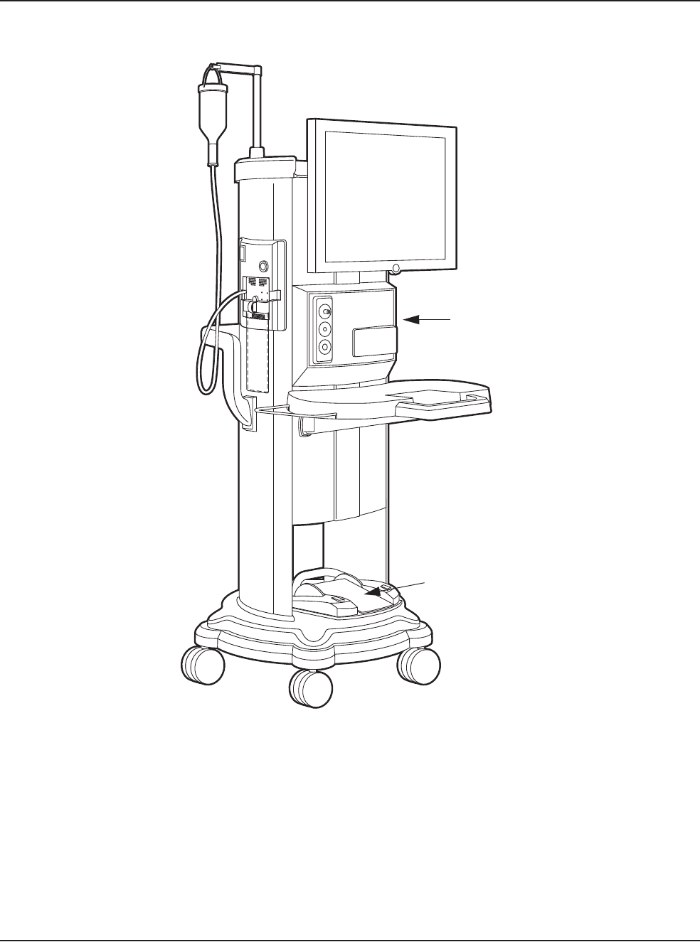
Figure 2.1 – WHITESTAR SIGNATURE™ System
1. Programmable IV Pole 4. WHITESTAR SIGNATURETM System console
with Integral Cart and Mayo Tray
2. FUSIONTM Tubing Cassette
3. Wireless Remote Control Module (Storage bay on
top of the system)
5. Footpedal
1
2
3
4
5
2 • System Components
WHITESTAR SIGNATURE™ System Rx Only – Z370147 Rev. C 1008 2-4
WHITESTAR
SIGNATURE™
System with
FUSION™ Tubing
Pack
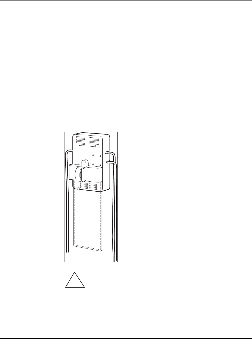
Each surgical procedure requires a disposable FUSION™ Tubing Cassette for
either the peristaltic pump or the Venturi pump. The FUSION™ Tubing Cassette
only works with the peristaltic pump, which is used in anterior/cataract surgeries.
The Dual Pump Tubing Cassette works with both the peristaltic pump and the
Venturi pump. With the Fusion™ Dual Pump Pack you can select either pump
while you are in a surgical case.
The tubing pack contains the following components:
• Tubing cassette with irrigation and aspiration tubing (administration set) with an
attached, sealed drain bag
• Infusion Sleeve
• Test Chamber – to test and prime/tune the phaco handpiece
• Mayo Stand Drape – to cover the Mayo tray and arm
• Monitor Drape – to cover the front of the touch screen
Figure 2.2 – FUSION™ Tubing Cassette
Proper handling and disposal methods for biohazards must be used when
you dispose of the tubing cassette, Mayo stand drape and monitor drape.
!

WHITESTAR SIGNATURE™ System Rx Only – Z370147 Rev. C 1008 3-1
Safety Precautions
Warnings
Symbol Definitions
System Disposal
Setup Sequence – Anterior Segment Surgery
Footpedal
Programmable IV Pole
Wireless Remote Control (Optional)
Surgical Media Center (SMC) (Optional)
Shutdown Sequence – Anterior Segment Surgery
3SYSTEM SETUP

3 • System Setup
WHITESTAR SIGNATURE™ System Rx Only – Z370147 Rev. C 1008 3-2
Safety Precautions Now that the system is set up and you have verified that all of the functions are
operating properly, you are almost ready to use your WHITESTAR
SIGNATURE™ System.
Read the following Safety Precautions and Warnings carefully before you use the
WHITESTAR SIGNATURE™ System in surgery.
1. The WHITESTAR SIGNATURE™ System is equipped with 3-prong power
plug which must be plugged into an outlet with a ground receptacle.
If the plug does not fit the outlet, contact an electrician. DO NOT modify or
remove the ground pin.
2. Do not use extension cords with your system.
3. Do not overload your electrical receptacle (outlet).
4. If the cord or plug is damaged, do not use the instrument. An electric shock or
fire hazard can result. Call AMO customer service to order a new cord.
5. The instrument has ventilation openings at the rear of the console to allow
ambient air intake and the release of heat generated during operation. If the
openings are blocked, heat build-up can cause system failures which can result
in a fire hazard.
6. Do not try to move the WHITESTAR SIGNATURE™ System cart on deep
pile carpets or over objects on the floor such as cables and power cords.
7. Take care not to trip over power and footpedal cords.
8. Do not try to lift the WHITESTAR SIGNATURE™ System cart.
9. Do not place the instrument on uneven or sloped surfaces.
10. Do not use disposables, accessories or other surgical instruments that are not
designed for this system. Use only parts recommended by AMO to achieve
optimum performance and safety.
11. Do not operate the WHITESTAR SIGNATURE™ System in a condensing
environment. Take care to protect the instrument from fluid sprays or fluid
buildup.
12. To protect the patient from contaminated fluids or handpieces, use only:
• sterile tubing cassettes
• sterile irrigation fluid
• sterile handpieces
13. Use caution when you extend, retract or swivel the Mayo stand articulating
arm. Stay clear of the hinged hardware.
14. Use caution when you use handpieces with sharp edges or pointed tips.

3 • System Setup
WHITESTAR SIGNATURE™ System Rx Only – Z370147 Rev. C 1008 3-3
15. Always replace the tubing cassette between cases.
16. Wrap the excess power cord neatly around the cord wrap on the back of the
console.
Changing Irrigation Flow
Use extreme caution when you lower or raise the balanced salt solution bottle to
decrease or increase fluid flow and pressure. If you lower the bottle too much it can
cause the anterior chamber to collapse. If you raise the bottle too high it can cause
the anterior chamber to deepen. To make sure that the bottle height does not go too
high, you can set the maximum bottle height on the Diagnostics screen.
Note: Use a new bottle of balanced salt solution at the start of each case.
Phacoemulsification without Adequate Irrigation
Operating phacoemulsification without an adequate irrigation flow can result in an
elevated temperature of the tip and subsequent damage to the eye tissue or could
cause the chamber to collapse. Confirm that there is irrigation flow before you
initiate phacoemulsification. A tight wound or the angle of the needle next to the
wound can also constrict the irrigation flow by pinching the coaxial irrigation
sleeve assembly on the needle of the phaco handpiece.
Power Failure during Surgery
If there is a loss of power during a procedure, you need to:
• Withdraw the handpiece from the eye
• Release the footpedal to Position 0
When power is restored:
• Select Prime/Tune to reprime the fluids and tune the phaco handpiece. Use
Bypass to reduce the length of prime time.
• Select the mode that was in use when power was lost (PHACO, IA, Vitrectomy
or Diathermy)
Connecting Handpieces
It is very important that the electrical connectors on the handpieces are completely
dry before they are connected to the WHITESTAR SIGNATURE™ System
receptacles. You can receive a “Handpiece Ground Fault Error” message if the
connector is wet.
Handling the Phaco Handpiece
The phaco handpiece is a very delicate instrument and must be handled with
EXTREME care. If the handpiece is dropped or receives any other significant
impact, the handpiece will not work properly. The ultrasonic titanium phaco tip
must never touch any solid material while in use.
Always flush the handpiece immediately following surgery.

3 • System Setup
WHITESTAR SIGNATURE™ System Rx Only – Z370147 Rev. C 1008 3-4
See cleaning instructions given in Chapter 9, “Care and Cleaning”.
Handpieces can be extremely hot immediately after sterilization. Use care and
caution when handling.
Phaco and Vitrectomy Operation
The phaco handpiece and the vitrectomy cutter must never be activated with the
tips exposed to air. If the tips are activated in the air, the useful life of the handpiece
and the cutter is reduced. If power is to be introduced to the phaco handpiece or the
vitrectomy cutter, the tips must be in a test chamber filled with a balanced salt
solution, in a container of balanced salt solution, or in the patient's eye.
Vitrectomy
Failure to properly attach the tubing to the appropriate vacuum or pressure source
can affect the vitrectomy cutter operation. Be sure to read the vitrectomy cutter
package insert for correct assembly and connection procedures.
Diathermy
When you enter the Diathermy mode, an audible tone should be heard. Also,
whenever diathermy power is applied, an audible tone should be heard.
The diathermy cable must be checked periodically for damage. If the cable shows
signs of damage, replace the cable immediately with the same type of cable. Use of
other types of cables can affect the diathermy performance.
During surgery, the diathermy output power must be as low as possible for the
intended purpose. AMO recommends the 30% setting to start.
The diathermy cable must be positioned in such a way that contact with the patient
or other leads is avoided. Grounded or ungrounded metal parts must not come in
contact with the patient when diathermy is used.
For proper operation of the diathermy, replace the handpiece with the same type.
Programmable IV Pole
Do not exceed the maximum weight of two 500 ml balanced salt solution bottles on
the IV pole bottle holder.
Wireless Remote Control and Wireless Foot Pedal
These devices comply with part 15 of the FCC (Federal Communications
Commission) Rules. Operation is subject to the following two conditions:
1. This device may not cause harmful interference.
2. This device must accept any interference received, including interference that
may cause undesired operation.
Any changes or modifications not expressly approved by Advanced Medical
Optics, Inc. can void the user's authority to operate the equipment.

3 • System Setup
WHITESTAR SIGNATURE™ System Rx Only – Z370147 Rev. C 1008 3-5
Note: This equipment has been tested and found to comply with the limits for a
Class A digital device, pursuant to part 15 of the FCC Rules. These limits
are designed to provide reasonable protection against harmful interference
when the equipment is operated in a commercial environment. This
equipment generates, uses, and can radiate radio frequency energy and, if
not installed and used in accordance with the instruction manual, may cause
harmful interference to radio communications. Operation of this equipment
in a residential area is likely to cause harmful interference in which case the
user will be required to correct the interference at his own expense.
Warnings
WARNING: All personnel who might operate this equipment must read
and understand the instructions in this manual before the system is used. Failure to
do so might result in the improper operation of the system. This device is only to be
used by a trained licensed physician.
WARNING: The fluid level in the balanced salt solution bottle must be
monitored by the surgical nursing staff. The result of a low bottle or an empty bottle
affects the fluid balance and the intra-ocular pressure (IOP) while aspirating. The
low or empty bottle can result in:
• The inadvertent chamber shallowing or collapse
• The Aspiration of tissue
• An ultrasonic wound heating commonly called wound burn (extreme case)
The surgical staff must monitor the fluid level at all times.
WARNING: DO NOT attempt to use the system if the system fails to
perform properly as stated in this manual.
WARNING: DO NOT use the System in the presence of flammable
anesthetics, or other flammable gases, near flammable fluids or objects, or in the
presence of oxidizing agents, as a fire could result.
!
!
!
!

3 • System Setup
WHITESTAR SIGNATURE™ System Rx Only – Z370147 Rev. C 1008 3-6
WARNING: This unit might interfere with any cardiac pacemaker fitted
to the patient; therefore qualified advice must be obtained prior to such use.
WARNING: The patient must not come into contact with metal parts
which are grounded or have appreciable capacitance to ground. The use of an
antistatic mat for this purpose is recommended.
WARNING: Proper handling and disposal methods for biohazards must
be used when you dispose of the tubing cassette, mayo stand drape and monitor
drape.
WARNING: Monitoring electrodes or other types of equipment must be
placed as far from those of the WHITESTAR SIGNATURE™ System as possible.
High current limiting devices are recommended for the protection of such systems.
Needle monitoring electrodes are not recommended.
WARNING: Keep the diathermy cord away from the patient and other
handpieces or leads (for example, monitoring electrodes).
WARNING: The output power selected must be as low as possible for
the intended purpose.
WARNING: Although this unit complies with all Electromagnetic
Interference (EMI) standards and requirements, it is possible that interference
provided by the operation of the HIGH FREQUENCY (HF) SURGICAL
EQUIPMENT can adversely influence the operation of other electronic equipment.
!
!
!
!
!
!
!

3 • System Setup
WHITESTAR SIGNATURE™ System Rx Only – Z370147 Rev. C 1008 3-7
WARNING: Skin to skin contact on the patient, for example, between
the arms and the torso is not recommended. Insert dry gauze to avoid contact, as
appropriate.
Note: The unit does not contains any neutral electrode.
Note: The diathermy output is bipolar.
Note: It is recommended that the condition of all inter-connecting and handpiece
cables be checked on a regular basis.
WARNING: Risk of burns and fire. Do not use the system near
conductive materials such as metal bed parts, inner spring mattresses, or similar
items. Replace electrode cables on evidence of deterioration.
WARNING: Hazardous electrical output. This equipment is for use only
by qualified personnel.
WARNING: Disconnect the power before you service the equipment.
WARNING: Remove the power cord from the power outlet when the
equipment is not in use.
WARNING: Do not obstruct the power outlet so that the power cord can
be readily removed, as needed.
WARNING: Not recommended for use in condensing environments. If
exposed to a condensing environment, allow the system to equilibrate to typical
operating room conditions prior to use.
!
!
!
!
!
!
!

3 • System Setup
WHITESTAR SIGNATURE™ System Rx Only – Z370147 Rev. C 1008 3-8
WARNING: This HIGH FREQUENCY (HF) SURGICAL
EQUIPMENT is specified for use without a NEUTRAL ELECTRODE.
WARNING: Failure of the HIGH FREQUENCY (HF) SURGICAL
EQUIPMENT could result in an unintended increase of output power.
WARNING: DO NOT try to replace the Wireless Remote Control
batteries. Call your AMO Technical Service representative to replace the batteries.
WARNING: Sterility assurance is the responsibility of the user. All non-
sterile accessories must be sterilized prior to use.
WARNING: Prior to using any invasive portions of the handpiece
assembly, examine under the microscope for any obvious damage, oxidation, or the
presence of foreign material. If any questionable characteristics are noted, use a
backup handpiece for surgery. Use of contaminated or damaged system accessories
can cause patient injury.
WARNING: Use of non-AMO approved products with the
WHITESTAR SIGNATURE™ System, can affect overall system performance and
is not recommended. AMO cannot be responsible for system surgical performance
if these products are utilized in surgery.
!
!
!
!
!
!
3 • System Setup
WHITESTAR SIGNATURE™ System Rx Only – Z370147 Rev. C 1008 3-9
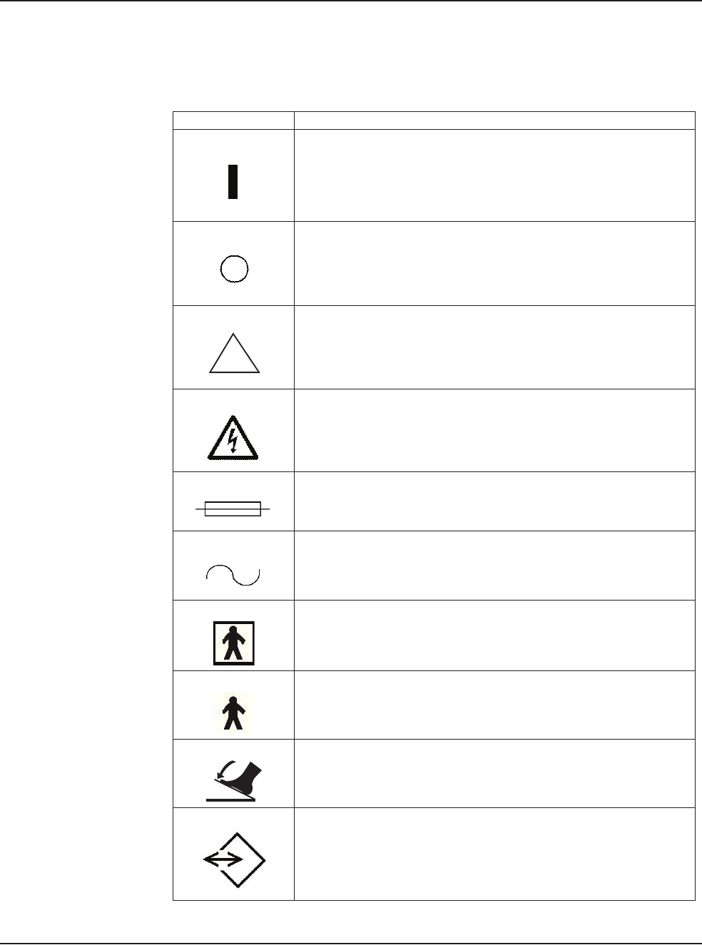
Symbol Definitions The following symbols appear on the WHITESTAR SIGNATURE™ System front
and back panels and in the software:
Table 3.1 – Symbol Definitions
Symbol Definition
Symbol on power switch indicates Power is On.
Symbol on power switch indicates Power is Off.
Indicates that there are important operating and
maintenance instructions included in the Owner’s and
Operator’s Manual.
Indicates the presence of uninsulated high voltage inside
the instrument. Risk of electric shock. Do not remove the
instrument cover.
Indicates fuse.
Single phase alternating current.
Patient applied part is isolated from earth ground.
Patient applied part is grounded OR no direct electrical
energy is involved.
Footpedal connection.
Communications Port
!
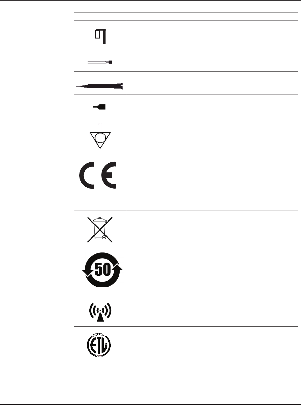
3 • System Setup
WHITESTAR SIGNATURE™ System Rx Only – Z370147 Rev. C 1008 3-10
Programmable IV Pole
Diathermy Receptacle
Phaco Handpiece Receptacle
Vitrectomy Cutter Connection
Potential Equalizer
Indicates compliance with the Medical Device Directive.
Separate Disposal/Collection Required
Environment Friendly Use Period in Years (RoHS)
Indicates compliance with IEC 60601-1-2:2001,
“Electromagnetic Compatibility Requirements and Tests
for Medical Electrical Equipment.”
ETL Listed Mark issued to those products that have met the
requirements of product safety standards for the United
States and Canada. (ETL formerly Edison Testing
Laboratory)
Symbol Definition
0050
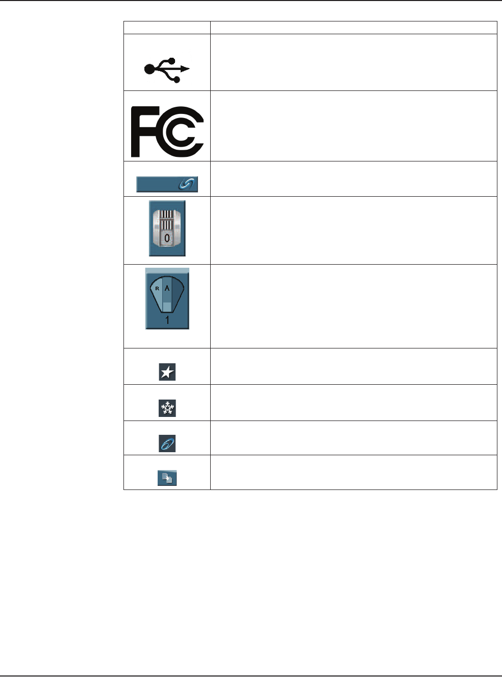
3 • System Setup
WHITESTAR SIGNATURE™ System Rx Only – Z370147 Rev. C 1008 3-11
Universal Serial Bus (USB) Port
Note: Use only AMO recommended USB stick drives.
Federal Communications Commission (FCC)
The FCC regulates interstate and international
communications by radio, television, wire, satellite and
cable under the FCC’s jurisdiction.
FUSION™ Mode button used to open the CASE settings
screen.
Single Linear Foot Pedal Icon. Shows the position of the
footpedal when the footpedal is pressed. The number
shown changes when the position is changed.
Advanced Control Pedal (Dual Linear) Icon. Shows the
position of the footpedal when the footpedal is pressed. The
number shown changes when the position is changed. The
letters indicate the location of Aspiration (A), Irrigation (I),
Phaco (P), Reflux (R), Whitestar Increment/Decrement
(WS) and Switch (S).
WHITESTAR® Technology is On.
WHITESTAR® Technology is On and ICE Pulse Shaping
is On.
Ellips™ Technology is On.
Reload button is used to cycle through the surgeon’s
programs.
Symbol Definition

3 • System Setup
WHITESTAR SIGNATURE™ System Rx Only – Z370147 Rev. C 1008 3-12
System Disposal WEEE
The electronic components of the WHITESTAR SIGNATURE™ System are
subject to the European Union Directive 2002/96/EC on Waste Electrical and
Electronic Equipment. This directive applies to all electronic equipment in the
European Union only.
The disposal to municipal waste is prohibited for electronic equipment subject to
this directive; this equipment must be treated or recycled. Each component that is
subject to this regulation is marked on the component itself with the following
symbol:
In some cases where the component’s size prohibits marking (such as handpieces)
the marking can be found on the directions for use and the warranty. Treatment
and/or recycling of the electronic equipment are provided at no cost to you. Please
see the contact information below for disposition of unwanted AMO electronic
equipment.
For disposal of your unit, contact your local AMO subsidiary or the AMO service
center nearest you.
Belgium
Contact
De Ceunynck Medical
nv/sa
Kontichsesteenweg 36
B-2630 AARTSELAAR
Belgium
Denmark
Distributor
AMO Denmark ApS
c/o Advanced Medical Optics
Norden AB
Kanalvagen 3A
SE 194 61 Upplands Vasby
Sweden
Finland
AMO Norden AB
Vantaa/Finland
Rajatorpantie 41 C, 3. krs
FIN-01640 Vantaa
Finland
Phone: +358 9 8520 2192
France
AMO France SAS
Greenside 15,
750 Avenue de Roumanille
06410 Biot
France
Phone: +33 4 93 00 11 95

3 • System Setup
WHITESTAR SIGNATURE™ System Rx Only – Z370147 Rev. C 1008 3-13
Germany
AMO Germany GmbH
Rudolf-Plank Strasse 31
D-76275 Ettlingen
Germany
Phone: +49 7243 729 444 (Hotline)
Greece
Distributor
Nexus Medicals s.a.
12th km Nat. Road Ave Athens-
Lamia & Zakynthou str.
14451 Metamorfosi
Athens
Greece
Ireland
AMO Ireland
Block B
Liffy Valley Office Campus
Quarryvale,
Co. Dublin
Ireland
Italy
AMO Italy Srl
Via Pio Emmanuelli, n.1
00143 Rome
Italy
Phone: +39 06 51 29 61
Netherlands
AMO Netherlands B.V.
Kantoorgebouw La Residence
Weverstede 25
3431 JS Nieuwegein
The Netherlands
Phone: +31 (0)30 600 8787
Norway
Distributor
Advanced Medical Optics
Norway AS
c/o Advanced Medical Optics
Norden AB
Kanalvagen 3A
SE 194 61 Upplands Vasby
Sweden
Poland
Distributor
Oko-Vita Polska sp.z.o.,
ul Marywilska 34,
03-228 Warsaw,
Poland
Portugal
Advanced Medical Optics Spain
S.L.
sucursal em Portugal
Praca Nuno Rodreguez dos Santos
no 7, 1600-171
Lisboa
Portugual
Russia
Distributor
Tradomed Ltd.,
Marksistskaya Str. 3,
Bld 1,
Moscow,
109147,
Russia
Spain
Advanced Medical Optics
Spain, S.L.
c/Dr. Zamenhof, n. 22, 4B
28027 Madrid
Spain
Phone: +34 9176 88 000

3 • System Setup
WHITESTAR SIGNATURE™ System Rx Only – Z370147 Rev. C 1008 3-14
RoHS (Restriction of Hazardous Substances)
For Chinese Regulation: Administrative Measure on the Control of Pollution
Caused by Electronic Information Products
Sweden
Advanced Medical Optics
Norden AB
Kanalvagen 3A
SE 194 61 Upplands Vasby
Sweden
Switzerland
Distributor
AMO Switzerland GmbH,
Churerstrasse 160 B,
CH-8808 Pfäffikon,
Switzerland
United Kingdom
AMO United Kingdom Ltd
Jupiter House
Mercury Park
Wooburn Green
High Wycombe
Buckinghamshire
HP10 0HH United Kingdom
Phone: +44 1628 551600
Table 3.2 – Names and Content of Toxic and Hazardous Substances or
Elements
Parts Name Toxic and Hazardous Substances or Elements
Pb Hg Cd Cr6+ PBB PBDE
Housing x o o x o o
Power Supply x o o x x x
Motherboard x o o o x x
Rear Panel
Assembly Board
x o o x x x
Pneumatics x o o x o o
LCD x x o o x x
Base Unit x o o o x x
Fluidics x o o x o o
o: Indicates that this toxic or hazardous substance contained in all of the
homogeneous materials for this part is below the limit requirement in SJ/
T11363-2006
x: Indicates that this toxic or hazardous substance contained in at least one of
the homogeneous materials used for this part is above the limit requirement in
SJ/T11363-2006 (Enterprises may further provide in this box technical
explanation for marking "X" based on their actual conditions.)

3 • System Setup
WHITESTAR SIGNATURE™ System Rx Only – Z370147 Rev. C 1008 3-15
Setup Sequence –
Anterior Segment
Surgery
The following is a general overview of the steps to be taken to prepare the
WHITESTAR SIGNATURE™ System for surgery:
1. Connect the WHITESTAR SIGNATURE™ System power cord to the rear of
system. Plug the power cord into a grounded power outlet.
2. Connect the footpedal to the rear panel receptacle.
3. Connect the compressed air line to the compressed air receptacle (optional).
4. Turn the system On at the back of the console.
5. Press the On/Off button on the Touch Screen monitor.
6. After completion of the Start Up Self Test, select the surgeon and program.
7. Install the tubing cassette, attach the required accessories (phaco, vitrectomy or
diathermy handpieces) and set up the tubing.
8. Prime and tune the handpieces. (Refer to Chapter 4, Equipment Operation,
Prime/Tune.)
9. Perform the final test of the fluidics and the handpiece integrity with the
footpedal. (Refer to Chapter 4, Equipment Operation, Verify Irrigation/
Aspiration Balance.)
3 • System Setup
WHITESTAR SIGNATURE™ System Rx Only – Z370147 Rev. C 1008 3-16
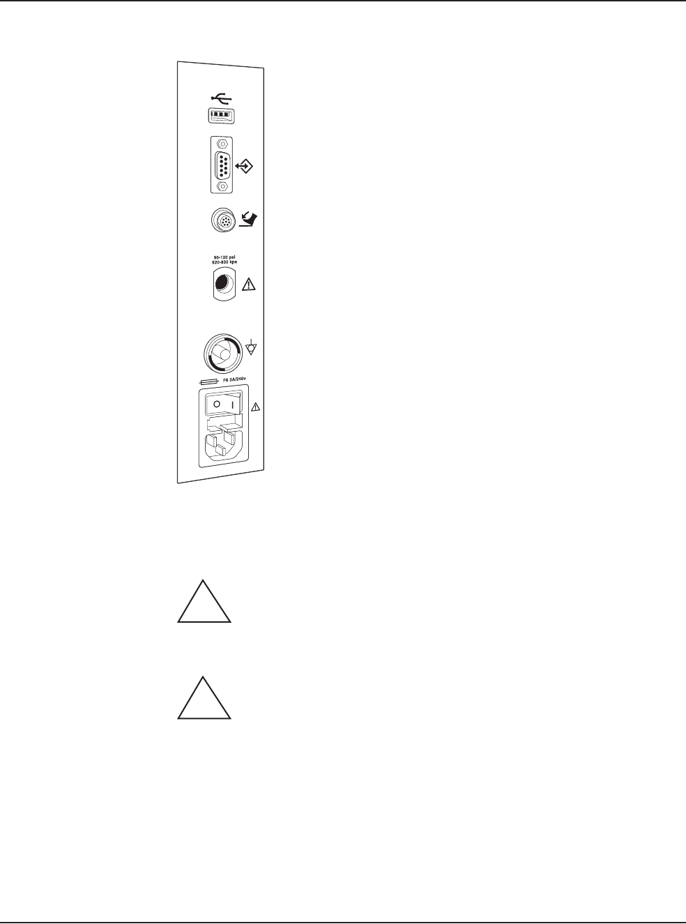
Figure 3.1 – Rear Panel Connections
Phacoemulsification Ultrasonic Handpiece
WARNING: Sterility assurance is the responsibility of the user. All non-
sterile accessories must be sterilized prior to use.
WARNING: Prior to using any invasive portions of the handpiece
assembly, examine under the microscope for any obvious damage, oxidation, or the
presence of foreign material. If any questionable characteristics are noted, use a
backup handpiece for surgery. Use of contaminated or damaged system accessories
can cause patient injury.
1. Use caution to prevent burns when handling the handpiece directly from
sterilization.
2. Remove the tubing cassette and accessories from the tubing pack and place
them in the sterile area.
1. USB Port 4. Compressed Air
2. Communications Port 5. Potential Equalizer
3. Foot Pedal Connector 6. Power Switch and Power Cord Connection
1
2
3
4
5
6
!
!
3 • System Setup
WHITESTAR SIGNATURE™ System Rx Only – Z370147 Rev. C 1008 3-17
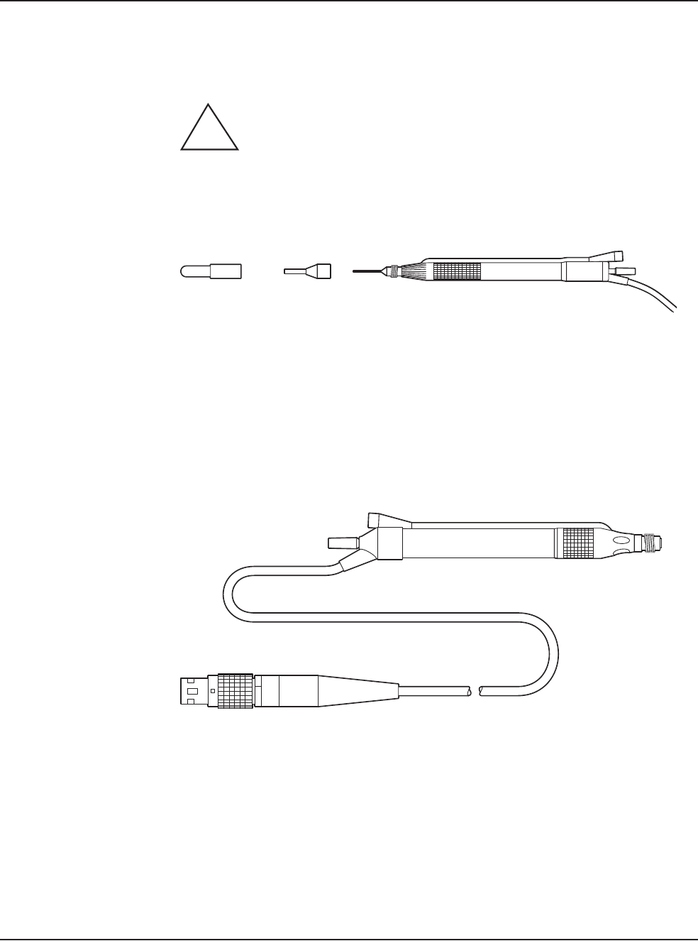
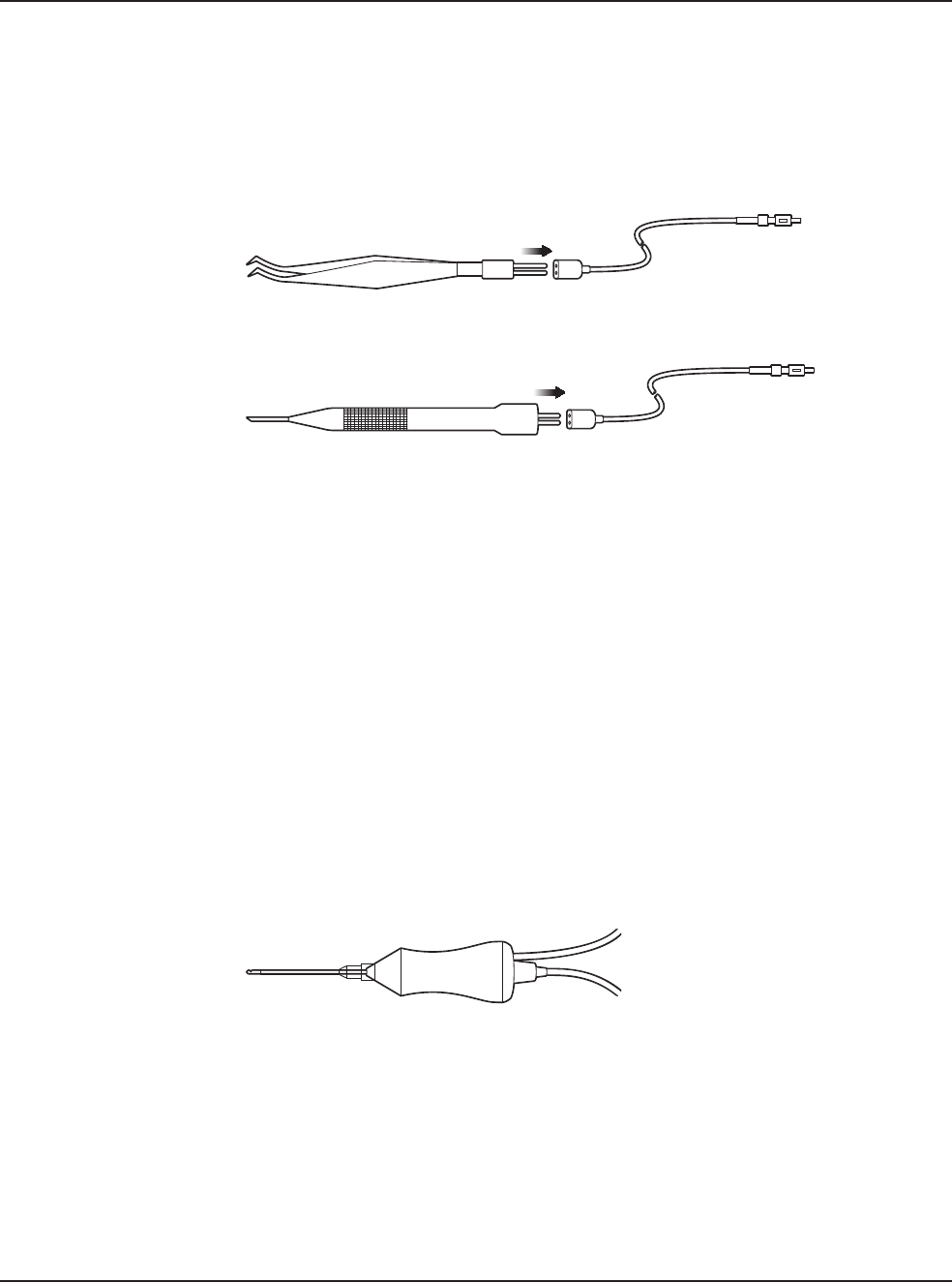
3. Assemble the phaco handpiece as shown below. You need the handpiece,
titanium phaco tip, the appropriate tip wrench, one of the infusion sleeves and
the test chamber.
CAUTION: NEVER ATTEMPT TO STRAIGHTEN A BENT
NEEDLE. THIS MIGHT PRODUCE A BROKEN TIP WHEN
ULTRASOUND IS APPLIED.
Figure 3.2 – Phaco Handpiece Assembly
4. Attach the connector end of the handpiece to the phaco receptacle on the front
of the WHITESTAR SIGNATURE™ System. Make sure there is no
moisture on the connectors prior to connecting. Moisture prevents the
handpiece from operating properly.
Figure 3.3 – Ellips™ Handpiece
Note: The Ellips™ handpiece can be used with WHITESTAR® Technology and
Ellips™ Technology phaco settings.
1. Test Chamber
2. Infusion Sleeve
3. Handpiece with Tip
!
1 2 3
3 • System Setup
WHITESTAR SIGNATURE™ System Rx Only – Z370147 Rev. C 1008 3-18
Irrigation/Aspiration Handpiece
1. Assemble the SOLO™ Irrigation/Aspiration (IA) Handpiece by attaching the
infusion sleeve.
Note: The infusion sleeve and the test chamber are provided in the
FUSION™ Tubing Pack. The LAMINAR™ Flow 20 ga. infusion
sleeves can also be used and are available with the OPOS20L or any
20 ga. LAMINAR™ Phaco Tip.
Figure 3.4 – IA Handpiece Assembly
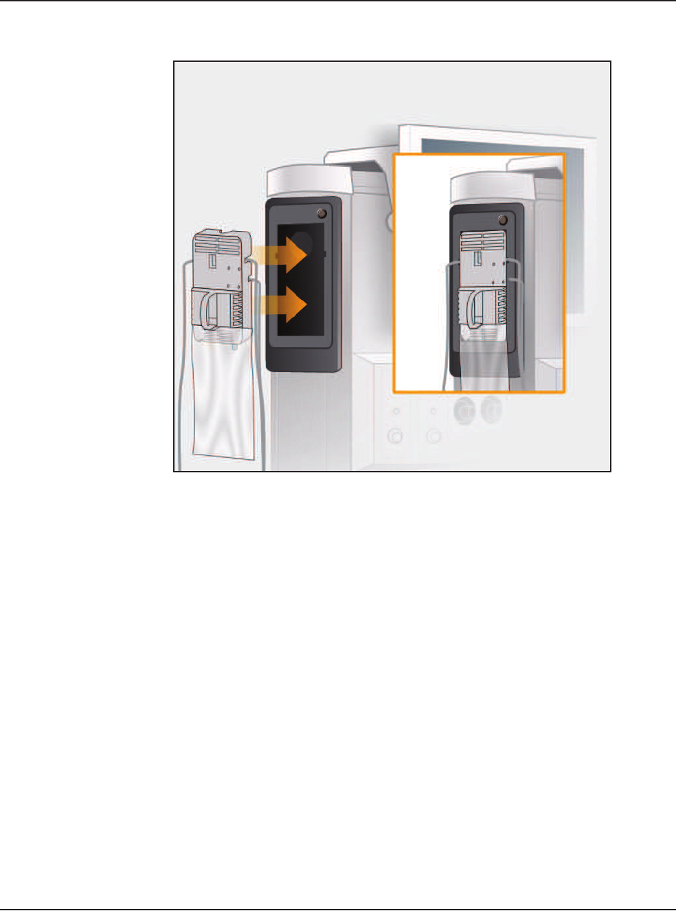
Load the FUSION™ Tubing Cassette
1. Open the tubing pack packaging.
2. Install the FUSION™ cassette into the side receptacle, as shown below.
3. Make sure that the drainage bag is properly attached to the cassette.
1 2
4
3
5
1. Infusion Sleeve 4. SOLOTM Curved Tip
2. SOLOTM Straight Tip 5. SOLOTM 45o Silicone Sleeve Tip
3. Handpiece
3 • System Setup
WHITESTAR SIGNATURE™ System Rx Only – Z370147 Rev. C 1008 3-19
Figure 3.5 – Loading the FUSION™ Tubing Cassette
Note: Press the button above the cassette to remove the cassette.
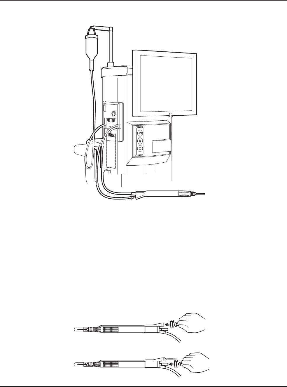
Setup Completion
IMPORTANT! Before you insert the spike into the bottle, shake the irrigation drip
chamber at the end of the irrigation tubing to confirm that the irrigation valve
moves. If the valve does not rattle, the valve cannot operate properly and irrigation
cannot flow.
1. Place a new bottle of balanced salt solution on the top of the system console.
2. Insert the drip chamber spike into the balanced salt solution bottle.
3. Hang the balanced salt solution bottle from the Programmable IV Pole and
squeeze the drip chamber.
4. Fill the drip chamber with fluid to the half-full level. The Programmable IV
Pole moves to the appropriate height automatically.
5. Raise or lower the pole if needed. Use the IV pole Up and Down arrows on
upper right of the touch screen. You can also use the Up/Down switch on the
console.
3 • System Setup
WHITESTAR SIGNATURE™ System Rx Only – Z370147 Rev. C 1008 3-20
Figure 3.6 – System Setup
6. Connect the IA tubing to the desired handpiece.
7. Insert the male luer end of the irrigation tubing into the phaco handpiece.
8. Attach the female luer fitting end of the aspiration tubing to the phaco
handpiece.
Note: To protect the patient from contamination, use only:
• sterile tubing sets
• sterile irrigation fluid
• sterile handpieces
Figure 3.7 – Phaco Handpiece Connections
3 • System Setup
WHITESTAR SIGNATURE™ System Rx Only – Z370147 Rev. C 1008 3-21
Diathermy
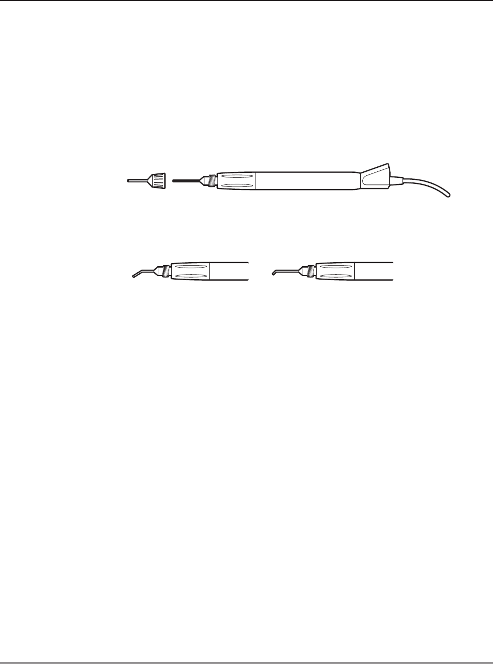
1. Connect the diathermy cord to the Diathermy Forceps or Pencil Probe.
2. Connect the diathermy cord to the diathermy receptacle on the front panel.
Figure 3.8 – Diathermy Forceps
Figure 3.9 – Diathermy Pencil
Note: Other diathermy accessories are regionally available. Contact your AMO
representative.
Vitrectomy
If vitrectomy is indicated during surgery:
1. Connect the AMO™ Vitrectomy Cutter as shown below. Vitrectomy requires
the following components:
• IA Tubing (from FUSION™ Tubing Cassette)
• Vitrectomy Cutter
• Vitrectomy Infusion Sleeve, or a 23 Gauge Limbal Infusion Needle, if
desired.
2. Assemble the handpiece using the instructions provided with the vitrectomy
cutter.
Figure 3.10 – Vitrectomy Cutter
3. Attach the connector end of the vitrectomy cord to the vitrectomy receptacle on
the front panel.

3 • System Setup
WHITESTAR SIGNATURE™ System Rx Only – Z370147 Rev. C 1008 3-22
Pre-Operative Sterilization
The Instrument Sterilization Procedures in Chapter 9, “Care and Cleaning” identify
the WHITESTAR SIGNATURE™ System instruments that must be sterilized prior
to each surgical case. The recommended sterilization techniques, times and
temperatures are given in Chapter 9, “Care and Cleaning”. AMO recommends that
you follow the sterilization guidelines to maximize the life of your WHITESTAR
SIGNATURE™ System instruments.
Footpedal The footpedal controls all of the WHITESTAR SIGNATURE™ System functions,
therefore, it is essential that you understand the footpedal operation.
The System software automatically detects if a footpedal and what type of
footpedal is connected during power up.
The footpedal settings and adjustments can be selected and preset for the footpedal
in the Configuration screen. Instructions for the footpedal settings are given in
Chapter 5, “Anterior Segment Surgery Operating Modes”. The footpedal housing
incorporates a handle, making the footpedal easy to grip for repositioning and
storage.
The Footpedal cable attaches to the footpedal connector on the rear of the console.
The Advanced Control Pedal (dual linear) can also be setup with a wireless
connection.
Note: You must NEVER handle the footpedal by the cable.
WARNING: Use only NiMH type batteries in the wireless Advanced
Control Pedal.
Figure 3.11 – Footpedal - Single Linear
!
3 • System Setup
WHITESTAR SIGNATURE™ System Rx Only – Z370147 Rev. C 1008 3-23
Figure 3.12 – Footpedal - Advanced Control Pedal (Dual Linear)
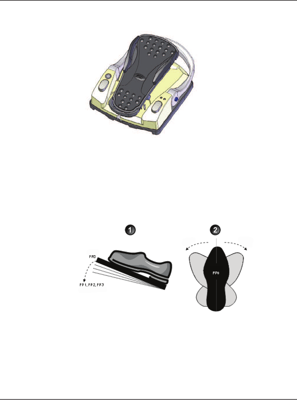
Footpedal Operation
The footpedal has three active “PITCH” ranges, which are referred to as Positions
1, 2 and 3. Position 0 is the Off position, and Position 3 is the fully pressed position.
The ranges are shown below. The Advanced Control Pedal has two Yaw switches.
Figure 3.13 – Footpedal “Pitch” and “Yaw” Positions
The footpedal position determines the function that is delivered by the handpiece,
which depends on the mode selected on the touch screen. When the footpedal has
been connected, place your foot on the pedal and press to the desired position. The
footpedal settings and programming are addressed in Chapter 5, “Anterior Segment
Surgery Operating Modes”.
1. Pitch 2. Yaw
Toe Down/Up Toe Right/Left
Configurable Ranges Configurable Ranges

3 • System Setup
WHITESTAR SIGNATURE™ System Rx Only – Z370147 Rev. C 1008 3-24
Note: Four to six minutes after the system is shutdown and power is turned off,
the wireless footpedal goes into a power-save mode. To turn on the
Wireless Footpedal after you start up the system, touch the Wake-up
button.
Reflux
Reflux is the controlled backflow of fluid through the aspiration port of the
handpiece. Reflux is used to gently release or dislodge unwanted material from the
handpiece tip. Reflux can also be used to “tent” the incision site to allow easier tip
insertion. Reflux pressure depends on bottle head pressure (IV pole height and
gravity) for the FUSION™ Fluidics pack (OPO70), and as such, is not intended to
clear a clogged handpiece. However, reflux can be used to identify a blockage.
The reflux action can be programmed on any available footpedal switch. When
Reflux is activated, the system reverses the peristaltic pump. This causes fluid to be
expelled from the aspiration line into or towards the eye.
The reflux is active until the footpedal switch is released.
The FUSION™ Fluidics pack (OPO70):
• allows an inter-connection of the irrigation line to the aspiration line, so that
sterile balanced salt solution can enter the aspiration line.
• has no time restriction for Reflux as there is no pump reversal
The DP pack (OPO71):
• includes support for the vacuum tank used in the Venturi vacuum system
• does not support inter-connecting the irrigation line to the aspiration line.
Therefore, only previously aspirated fluid is being refluxed.

3 • System Setup
WHITESTAR SIGNATURE™ System Rx Only – Z370147 Rev. C 1008 3-25
Programmable IV
Pole
The Programmable IV Pole is controlled by the Up and Down arrows on the upper
right of the touch screen, next to the bottle height indicator. The buttons on the
remote control and the switch on the side of the console can also be used to control
the IV Pole. These controls are used to raise and lower the pole, and the height is
indicated in the Programmable IV Pole screen. The Programmable IV Pole moves
at a rate of approximately 6 cm (2 inches) per second.
The Programmable IV Pole is adjustable from 0 to 104 centimeters, and can be set
for either inches or centimeters. The height measurement is relative to the distance
from the irrigation valve to the center of the drip chamber. The Programmable IV
Pole height for each fluidic mode or submode (PHACO, IA, VIT) is saved in the
WHITESTAR SIGNATURE™ System memory. A Maximum IV Pole height can
be set on the Diagnostics screen.
When a surgery mode is selected, the Programmable Power IV Pole automatically
moves to the preset height. To manually adjust the IV pole height, use the Up and
Down arrows on the touch screen. Manual adjustments to the IV pole can also be
made by pressing the rocker switch located on the side of the console. If a
maximum height has been set, the IV pole will not move above that height.
3 • System Setup
WHITESTAR SIGNATURE™ System Rx Only – Z370147 Rev. C 1008 3-26
Wireless Remote
Control (Optional)
The wireless remote control keypad can be used to operate the WHITESTAR
SIGNATURE™ System. All Modes, Programs, Diagnostics and End Case can be
accessed and adjustments to the settings can be made with the remote control. The
buttons on the remote keypad work the same as the controls on the WHITESTAR
SIGNATURE™ System touch screen.
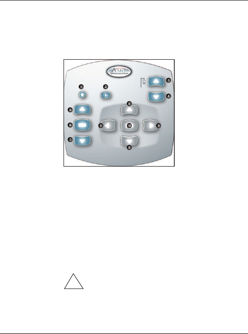
Figure 3.14 – Wireless Remote Control Module
When not in use, store the Wireless Remote Control on the top of the system to
charge the batteries.
After you turn the system On, press the Remote Control Backlight button to
activate the Remote Control. When the system is Off the Remote Control is in a
power save mode.
Note: After four to six minutes of idle time, the Remote Control goes into a power-
save mode. To turn the Remote Control on, press the Backlight button.
WARNING: DO NOT try to replace the Wireless Remote Control
batteries. Call your AMO Technical Service representative to replace the batteries.
1. Remote Backlight On 6. Mode Select
2. Reload 7. Mode Down
3. IV Pole Up 8. Navigation Up/Down
4. IV Pole Down 9. Navigation Left/Right
5. Mode Up 10. Select
!
3 • System Setup
WHITESTAR SIGNATURE™ System Rx Only – Z370147 Rev. C 1008 3-27
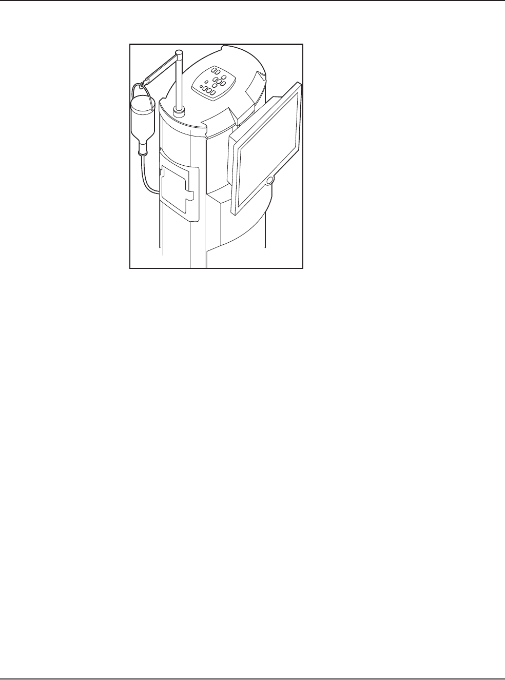
Figure 3.15 – Wireless Remote Control Module Storage
Surgical Media
Center (SMC)
(Optional)
The Surgical Media Center (SMC) is used to record the surgery and the instrument
settings to be viewed at a later date and time. The surgery is displayed on a monitor
with the instrument settings. The SMC hardware is connected to your
WHITESTAR SIGNATURE™ System Communications port on the rear panel.
(See Figure 3.1 Rear Panel Connections.)
1. To configure the Surgical Media Center, select:
• Configuration
• System Configuration
•SMC
3 • System Setup
WHITESTAR SIGNATURE™ System Rx Only – Z370147 Rev. C 1008 3-28
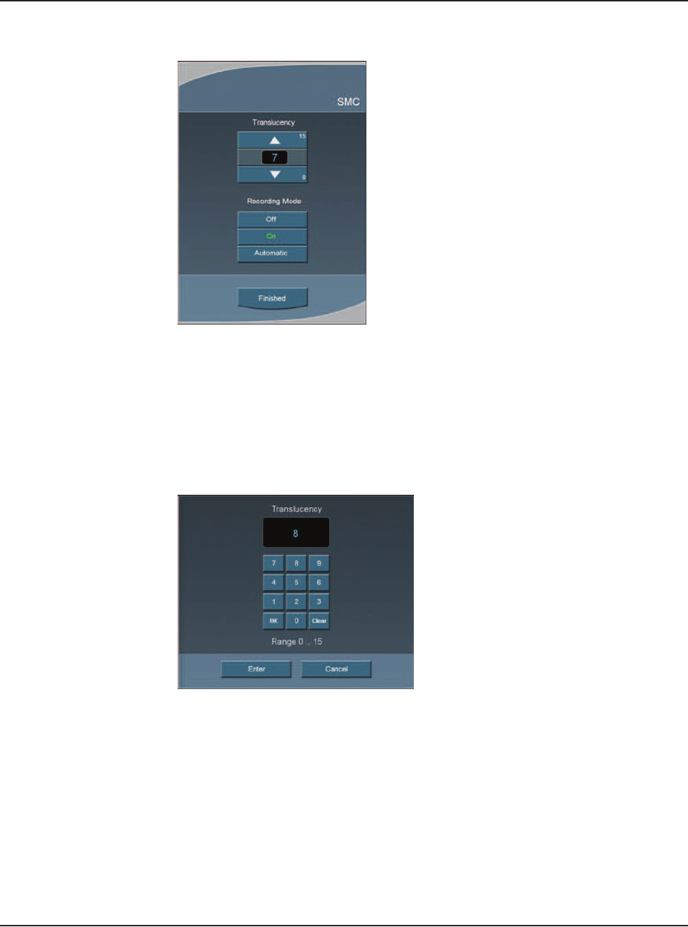
Figure 3.16 – Surgical Media Center Pop-up Window
2. Use the Up and Down arrows to adjust the settings. Translucency is used to
make the overlay (instrument settings) more or less opaque.
Note: Press on the number in the control panel to open a numeric keypad and
enter the required value. Press Enter on the Keypad pop-up window
when you are finished.
Figure 3.17 – Numeric Keypad Pop-up Window
3. Select the Recording Mode. Off, On, or Automatic. If the Recording Mode
is On, the recording continues between cases. Automatic stops recording
between cases.
Note: The Footpedal Switch can be set up to activate the SMC Record function.
4. Press Finished to close the pop-up window.

3 • System Setup
WHITESTAR SIGNATURE™ System Rx Only – Z370147 Rev. C 1008 3-29
Shutdown Sequence
– Anterior Segment
Surgery
The following is a general overview of the steps to be taken to shut the System
down after surgery:
1. Select End Case.
2. Select Shutdown. At the prompt, select Yes.
3. Wait for shutdown sequence to complete.
4. Turn the system Off at the back of the console.
5. Remove the power cord from the power outlet.
6. Wrap the excess power cord neatly around the cord wrap on the back of the
console.
7. Place the footpedal in the storage area on the console.
8. Place the Wireless Remote Control on top of the console to charge.
9. Refer to Chapter 9, “Care and Cleaning”, Cleaning Procedures for additional
information.

WHITESTAR SIGNATURE™ System Rx Only – Z370147 Rev. C 1008 4-1
Display Screens and Controls
Language Selection
Startup
Select Program and Install the FUSION™ Tubing Cassette
Prime/Tune
Verify Irrigation/Aspiration Balance
Priming for Vitrectomy
Selecting and Changing Mode Parameters
4EQUIPMENT OPERATION
4 • Equipment Operation
WHITESTAR SIGNATURE™ System Rx Only – Z370147 Rev. C 1008 4-2
Display Screens and
Controls
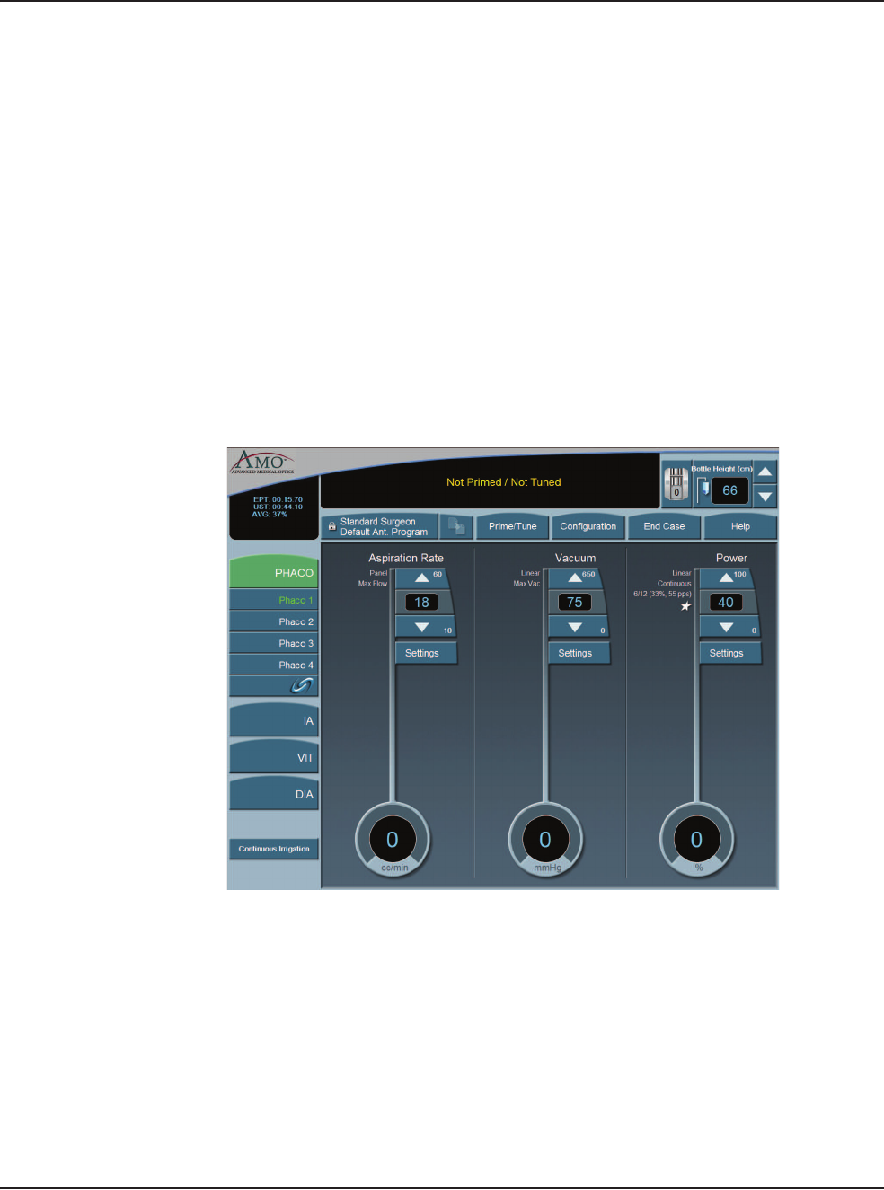
The touch screen is designed to give you visual indication of the status of the
control systems at all times. When a mode (DIA, PHACO, IA, or VIT) is selected,
the current settings are shown on the screen. As adjustments to settings are made,
the screen shows the changes. The screens and controls are shown below.
Each Anterior segment surgery mode and submode has their own distinct screen
setup:
• Irrigation/Aspiration
• Phaco without OCCLUSION MODE™
• Phaco with OCCLUSION MODE™ and/or CASE (FUSION™ MODE)
• Phaco with Ellips™ technology
• Vitrectomy
• Diathermy
Figure 4.1 – PHACO Screen
Additionally, there are screens or sub-screens for:
• Prime/Tune
• End Case
• Program
• Sounds
• Footpedal
• Database
• Diagnostics
4 • Equipment Operation
WHITESTAR SIGNATURE™ System Rx Only – Z370147 Rev. C 1008 4-3
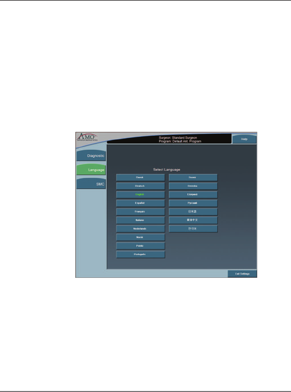
Language Selection The WHITESTAR SIGNATURE™ System features a 17-language user interface.
Before you proceed, select one of the languages for your touch screen and controls.
(English is the default language).
1. To access the Select Language screen, from the main screen, select:
• Configuration
• System Configuration
•Language
2. Select the desired language from the listing.
3. Press Yes at the confirmation pop-up. The screen automatically changes to the
selected language.
4. Press Exit Settings to proceed with the selected language.
Figure 4.2 – Language Screen
Note: On any screen, if you press the screen about 25 times, the System changes
to the default language (English).You must press the same spot on the
screen.
4 • Equipment Operation
WHITESTAR SIGNATURE™ System Rx Only – Z370147 Rev. C 1008 4-4
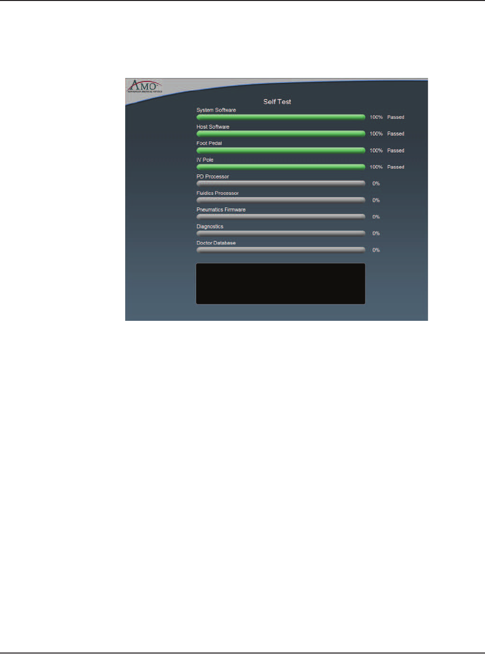
Startup After you have turned on the WHITESTAR SIGNATURE™ System, the system
performs a series of Self Tests.
Figure 4.3 – Self Test
After start up, the screen shows the available Surgeons and Programs that can be
selected.
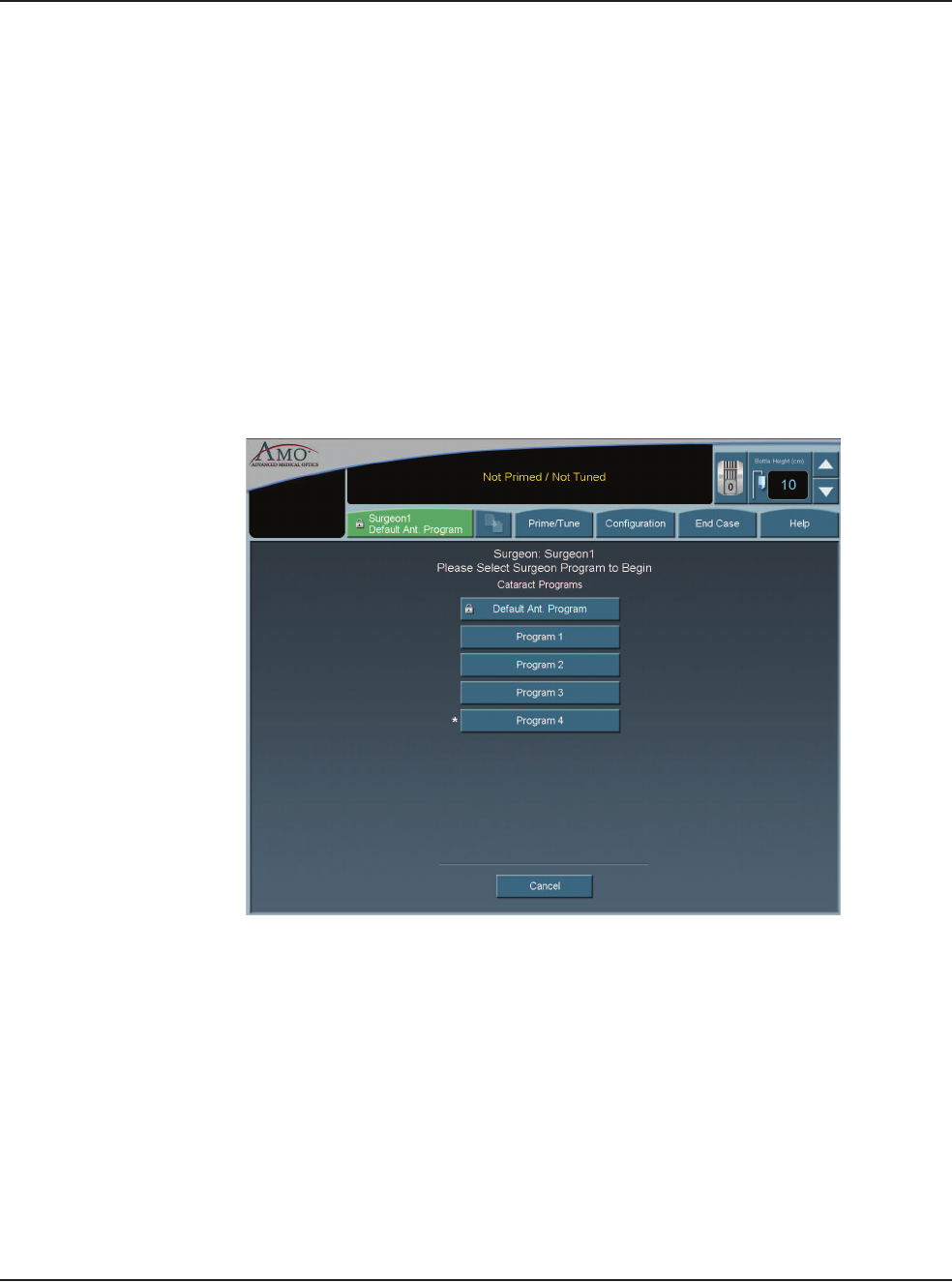
You can now select a Surgeon and a Program. A Program (or Surgeon Name) is a
set of pre-established operating settings for each operating mode. The
WHITESTAR SIGNATURE™ System allows you program up to a maximum of
50 Surgeon names, and 20 customized surgeon setups (programs) for each surgeon.
4 • Equipment Operation
WHITESTAR SIGNATURE™ System Rx Only – Z370147 Rev. C 1008 4-5
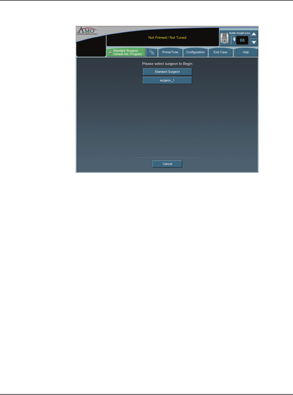
Figure 4.4 – Select Surgeon Screen
If Standard Surgeon is the only surgeon set up, this screen is not shown, and the
System proceeds immediately to the tubing cassette installation screen.
From the Main Menu you can:
• Select a Surgeon/Program and begin surgery based on the values of that
program
• Enter the Settings (Configuration) page, where you can edit, add, or delete
programs and setup operating parameters
• Enter the End Case screen (Refer to Chapter 5, Anterior Segment surgery
Operating Modes, End Case.)
4 • Equipment Operation
WHITESTAR SIGNATURE™ System Rx Only – Z370147 Rev. C 1008 4-6
Select Program and
Install the
FUSION™ Tubing
Cassette
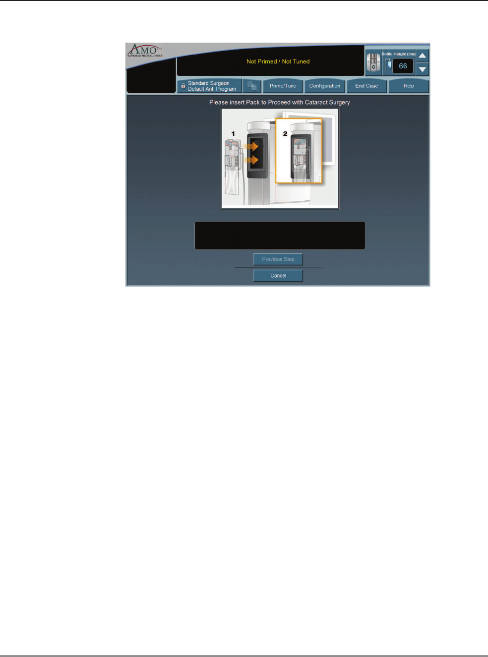
After you select a surgeon, you must select a program from the surgeon's available
programs. If this is the first time the system has been used, AMO Default Program
is the only program that appears on the screen. The first program you create uses
the AMO Default Program settings as a starting point. You can modify the
settings and Save As a specific program or surgeon name. The system does not let
you overwrite the AMO Default Program when you press SAVE.
If a surgeon only has one program set up, this screen is not shown, and the System
proceeds immediately to the tubing cassette installation screen for the type of
program that is set up for that surgeon. The System automatically recognizes the
type of tubing casette that is installed.
Note: An asterisk next to a program name indicates that the surgeon as selected
that program as their default program.
Figure 4.5 – Select Program Screen
4 • Equipment Operation
WHITESTAR SIGNATURE™ System Rx Only – Z370147 Rev. C 1008 4-7
Figure 4.6 – Install Cassette Screen
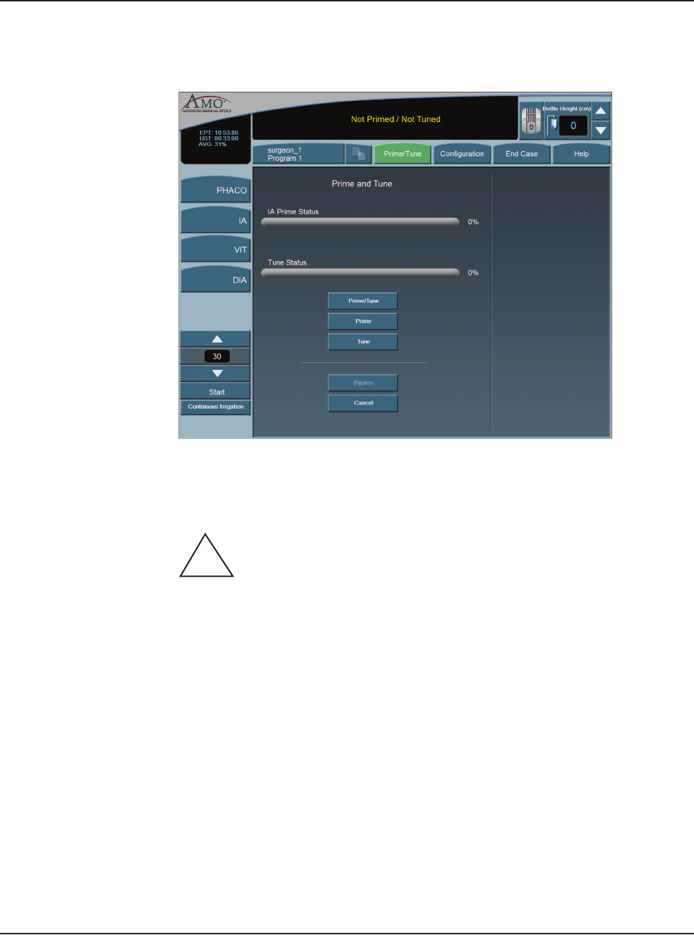
Prime/Tune Prime/Tune is required before surgery is performed to fill the IA tubing with fluid,
perform a vacuum check and to test and characterize the phaco handpiece. You
must Prime and Tune:
• before each procedure
• anytime the handpiece is reconnected
• after you have inserted or replaced a tubing cassette
Continuous Irrigation can be selected to allow fluid to free flow from the bottle in
order to collect fluid.
Note: Before you Prime and Tune, the Cup Fill feature can be used to fill cups. Use
the Up and Down arrows to set the amount needed, either 30, 60 or 90 cc, to fill the
cup and then press Start. The Cup Fill stops when the selected amount is dispensed
or Stop is pressed. You can still use Continuous Irrigation to fill cups.
IA Prime is designed for a procedure that does not require a phaco handpiece. Tune
is designed for a quick tune of the phaco handpiece with an IA tubing set. Tune can
be used if a phaco tip is replaced during a procedure.
When you Bypass prime the overall fluidics prime sequence is shortened and the
time to prime the WHITESTAR SIGNATURE™ System is reduced. Bypass can
be used if Continuous Irrigation has been used or the I/A tubing was primed. If
the I/A tubing was not properly primed, errors can occur.
To access the Prime/Tune routines, press the Prime/Tune button. The main
console shows the Prime/Tune screen with all prime and tune options.
4 • Equipment Operation
WHITESTAR SIGNATURE™ System Rx Only – Z370147 Rev. C 1008 4-8
Note: Prime/Tune is a combination of Tune followed by IA Prime.
Figure 4.7 – Prime and Tune Screen
The WHITESTAR SIGNATURE™ System tracks the successful completion of the
Prime and Tune cycle independently. In the event a retune is required (new tip,
failed tune), only the Tune needs to be selected and run.
CAUTION: THE PHACO HANDPIECE AND VITRECTOMY
CUTTER MUST NEVER BE ACTIVATED WITH THE TIP IN THE AIR.
EXPOSURE OF THE TIP TO AIR DRASTICALLY REDUCES THE
USEFUL LIFE OF THE HANDPIECE. IF POWER IS TO BE
INTRODUCED TO THE PHACO HANDPIECE OR VITRECTOMY
CUTTER, THE TIP MUST BE IN A TEST CHAMBER FILLED WITH
BALANCED SALT SOLUTION, IN A CONTAINER OF BALANCED SALT
SOLUTION OR IN THE PATIENT’S EYE.
Suggestions for Priming the Handpieces
Always fill the test chamber completely prior to running the Prime/Tune Cycle.
Do not lay the handpiece and the empty test chamber down and have the system fill
the test chamber. This allows air to collect in the test chamber and can produce an
error.
To collect the balanced salt solution:
1. Use the test chamber, a medicine cup, or similar container.
!

4 • Equipment Operation
WHITESTAR SIGNATURE™ System Rx Only – Z370147 Rev. C 1008 4-9
2. Use the Up and Down arrows to increase or decrease the amount of the fluid
needed.
3. Press Start to turn on Cup Fill.
4. Use Stop to turn off Cup Fill before the requested amount of fluid is dispensed.
5. Perform a full Phaco Prime/Tune.
The Prime/Tune screen indicates the progress of the priming process.
1. Use the Cup Fill feature to fill the test chamber with fluid and to eliminate all
air. If the test chamber is attached to the handpiece, remove the test chamber
before you start the Cup Fill process.
2. Place the test chamber over the handpiece tip and the sleeve hub.
3. Press the Prime/Tune button, this starts the Prime and Tune sequences.
• To perform a Prime only, press the Prime button.
• To perform a Tune only, press the Tune button.
4. Make sure the movement of the IV pole is not blocked by low ceilings.
5. Watch the fluid fill the drip chamber. The fluid moves toward the handpiece
and fills the test chamber.
6. The touch screen indicates the progress of the Prime and Tune process.
7. As the tubing lines are filled, the system software performs functional checks.
The checks include:
• Monitoring for the presence of irrigation flow (bottle height)
• Leaks (via vacuum rise checks)
8. If the phaco handpiece is plugged in and Prime/Tune or Tune was selected,
the system automatically includes a handpiece tuning test concurrently with the
prime cycle.
• At the end of the priming sequence, the WHITESTAR SIGNATURE™
System makes an audible sound to indicate that Prime process is complete.
• At the end of the phaco tuning test, the WHITESTAR SIGNATURE™
System makes an audible alert sound to indicate that tune process is
complete.
9. To discontinue Prime or Tune during the process, select Cancel.
10. When Prime and Tune are complete, the system automatically proceeds to the
preprogrammed submode or Phaco 1 operating mode. It is important that you
verify the IA balance prior to operating.
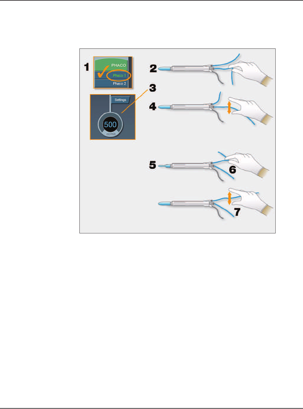
4 • Equipment Operation
WHITESTAR SIGNATURE™ System Rx Only – Z370147 Rev. C 1008 4-10
Verify Irrigation/
Aspiration Balance
We strongly recommend verifying that Irrigation/Aspiration is balanced properly
for the settings to be used in surgery.
Figure 4.8 – Irrigation/Aspiration Balance Procedure
To verify Irrigation/Aspiration balance:
1. In PHACO 1 mode, hold the handpiece at approximate patient eye level.
2. Occlude the aspiration line just below the handpiece, while you press and hold
the footpedal in position 2. Make sure the footpedal is connected. (Refer to
Chapter 3, System Setup, Footpedal.)
3. The actual vacuum level should rise to the preset level.
4. Release the aspiration line and watch the test chamber to make sure that the test
chamber does not collapse. A slight shallowing of the test chamber is normal.
5. If the test chamber collapses, raise the IV bottle height or lower the vacuum
setting.
6. Pinch the irrigation tubing at the handpiece and watch for the test chamber to
collapse.
7. Release the irrigation line and the test chamber should fill.
8. Press Reset in the upper left corner of the screen to open the Reset Timers
pop-up window. Press Yes to rest the timers. You are now ready to begin
surgery.
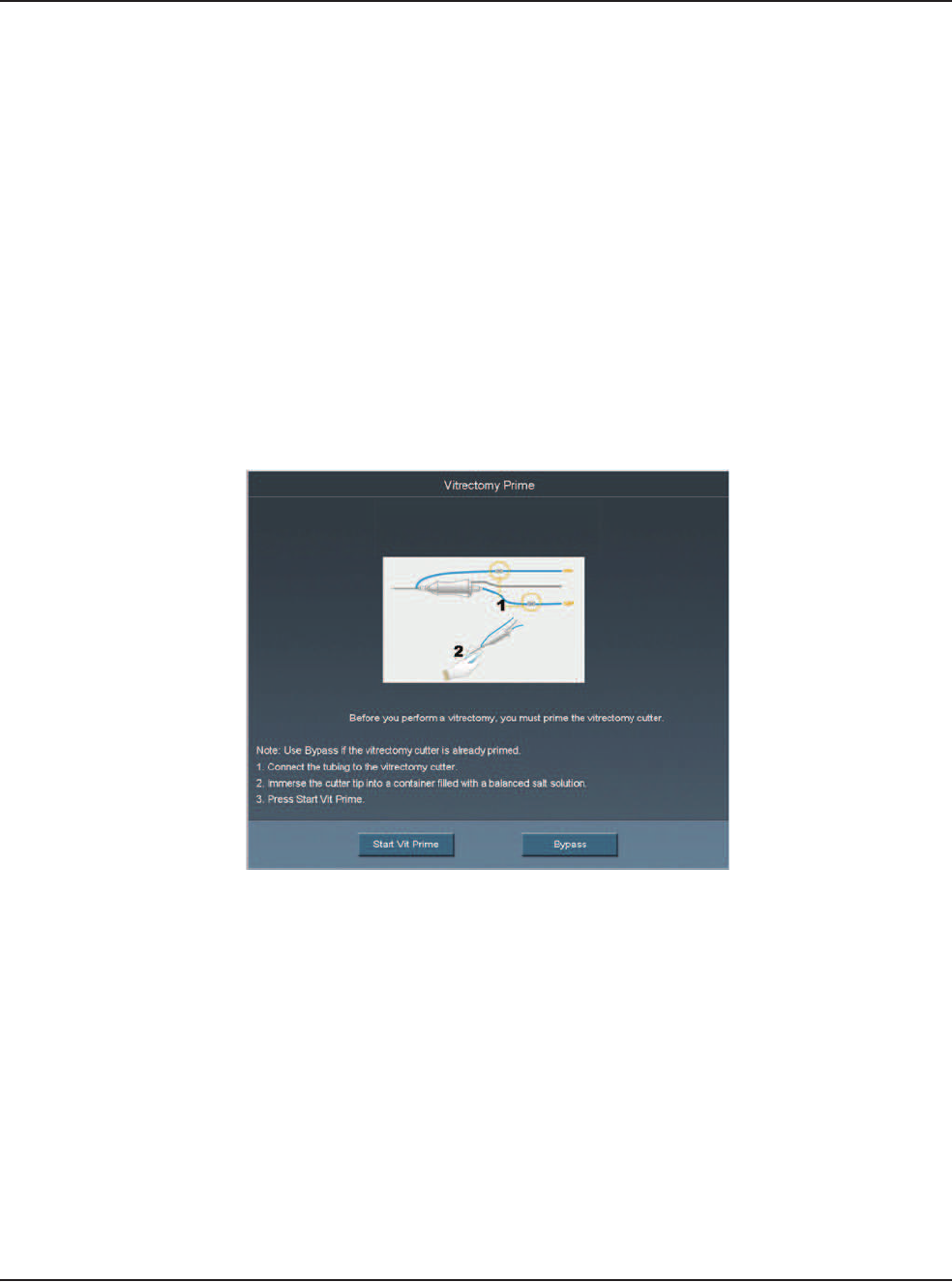
4 • Equipment Operation
WHITESTAR SIGNATURE™ System Rx Only – Z370147 Rev. C 1008 4-11
Priming for
Vitrectomy
Before you perform vitrectomy, we recommend you prime the handpiece in order
to reduce the chance of errors. Each time you select vitrectomy mode you are
prompted to prime the vitrectomy handpiece. If you do not need to prime, press
Bypass.
To prime the handpiece:
1. Attach the irrigation and aspiration cassette pack tubing together.
2. Press Prime on the Prime/Tune screen.
3. Press the VIT button to enter VIT mode.
4. Follow the instructions on the screen.
5. Press Start Vit Prime. The screen closes automatically when the handpiece is
primed.
Note: If you must perform vitrectomy in the middle of phaco surgery, perform
steps 3 through 5.
Figure 4.9 – Vitrectomy Prime Procedure

4 • Equipment Operation
WHITESTAR SIGNATURE™ System Rx Only – Z370147 Rev. C 1008 4-12
Selecting and
Changing Mode
Parameters
The system's graphical user interface (GUI) and touch screen is designed for
ease-of-use, consistent application and maximum informational display during all
operating modes.
Your interface with the system requires only three basic steps, which apply to all of
the selections, settings and operations. Once this basic organization is understood,
you can move quickly and easily through all of the system functions and
operations.
The touch screen is organized into panels. The top panel shows current status,
configuration options, the bottle height, and the footpedal icon. The left-side
column lists the operating modes and submodes. The main panel that dominates the
screen shows current operating levels for aspiration, vacuum and power.
• To switch operating modes or submodes, press a button in the left panel. The
control panels in the main panel show the operating levels for that mode.
• To make basic changes to the settings, press the Up and Down arrows to increase
or decrease a value.
Note: Press on the number in the Settings control panel to open a numeric keypad
and enter the required value. Refer to Figure 3.17 Numeric Keypad Pop-up
Window. Press Enter to close the Keypad window.
• To change other control panel settings, such as Panel or Linear power, press the
Settings button on that control panel. A Settings window opens, and you can
make your selections.
Figure 4.10 – PHACO Mode Screen
• To make overall changes to a program, press Configuration on the top panel.
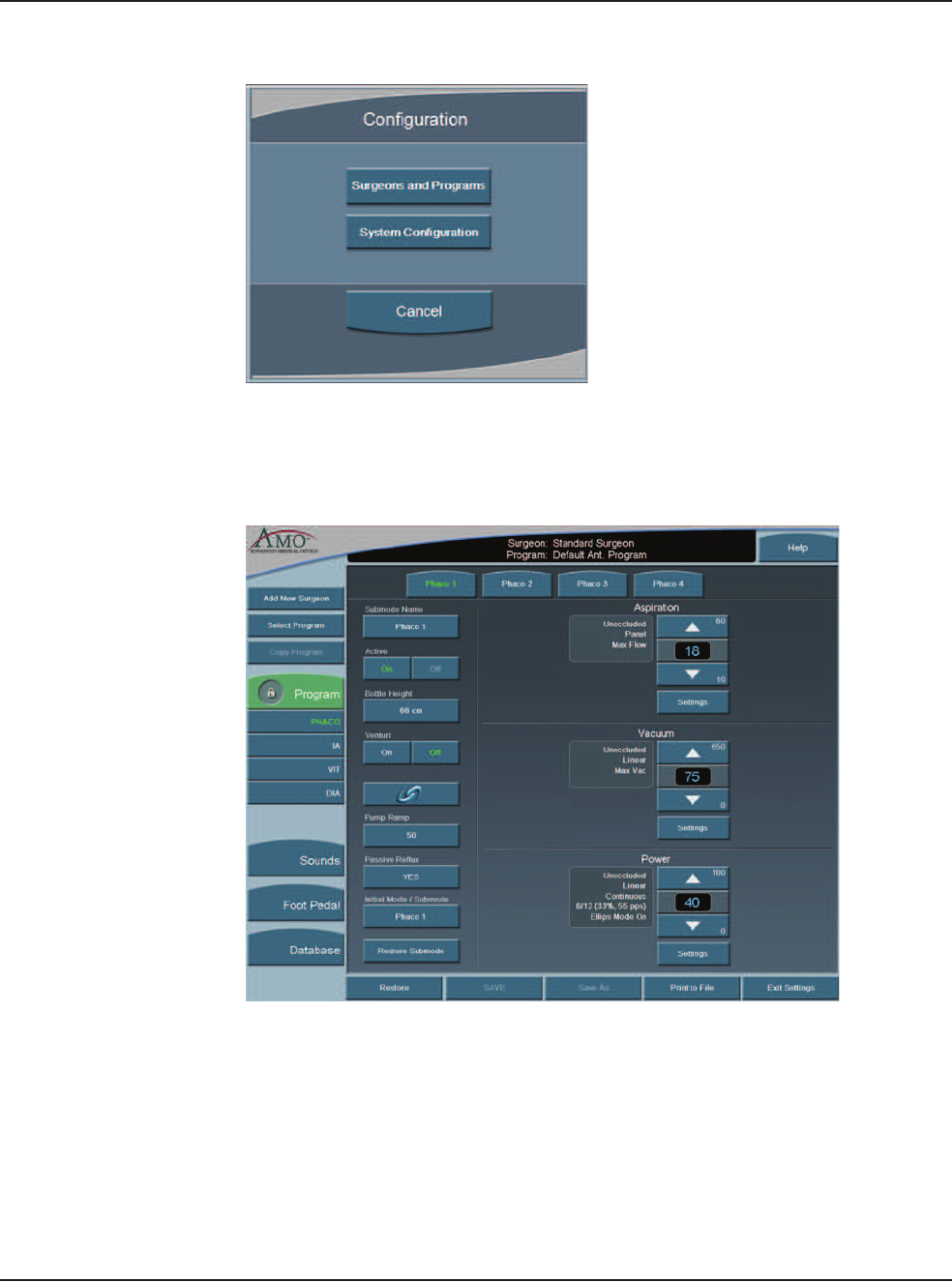
4 • Equipment Operation
WHITESTAR SIGNATURE™ System Rx Only – Z370147 Rev. C 1008 4-13
Figure 4.11 – Configuration Pop-up Window
• Press Surgeons and Programs to access surgeon names and their associated
program setups.
Figure 4.12 – PHACO Submode Configuration Screen

WHITESTAR SIGNATURE™ System Rx Only – Z370147 Rev. C 1008 5-1
Operating Mode Descriptions
Fusion™ Fluidics Phaco
Programming the Modes and Settings
Anterior Segment – Recommended Settings
OCCLUSION MODE™ Phaco Settings
Passive Reflux
Ellips™ Technology
5ANTERIOR SEGMENT SURGERY
OPERATING MODES
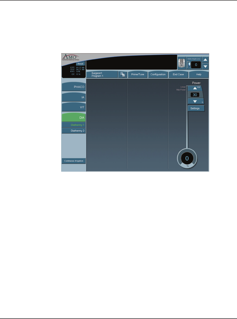
5 • Anterior Segment Surgery Operating Modes
WHITESTAR SIGNATURE™ System Rx Only – Z370147 Rev. C 1008 5-2
Operating Mode
Descriptions
Diathermy
While the system is priming, you can select the Diathermy (DIA) mode (a function
which does not require irrigation and aspiration flow) and perform Diathermy
procedures. This process is referred to as a Diathermy during Prime.
Figure 5.1 – Diathermy Mode Screen
If Diathermy is selected during Prime, the screen indicates the Prime/Tune status
and any messages associated with the prime and/or tune.
The WHITESTAR SIGNATURE™ System provides power for bipolar
coagulation or diathermy. The amount of diathermy power is shown on the
Diathermy screen. If Panel power is selected, you can increase or decrease power
by pressing the Up or Down arrows on the Power control panel. If the Linear mode
is selected, the power is controlled with the footpedal up to the maximum preset
value.
Note: Press on the number in the Settings control panel to open a numeric keypad
and enter the required value. Refer to Figure 3.17 Numeric Keypad Pop-up
Window. Press Enter when you are finished.
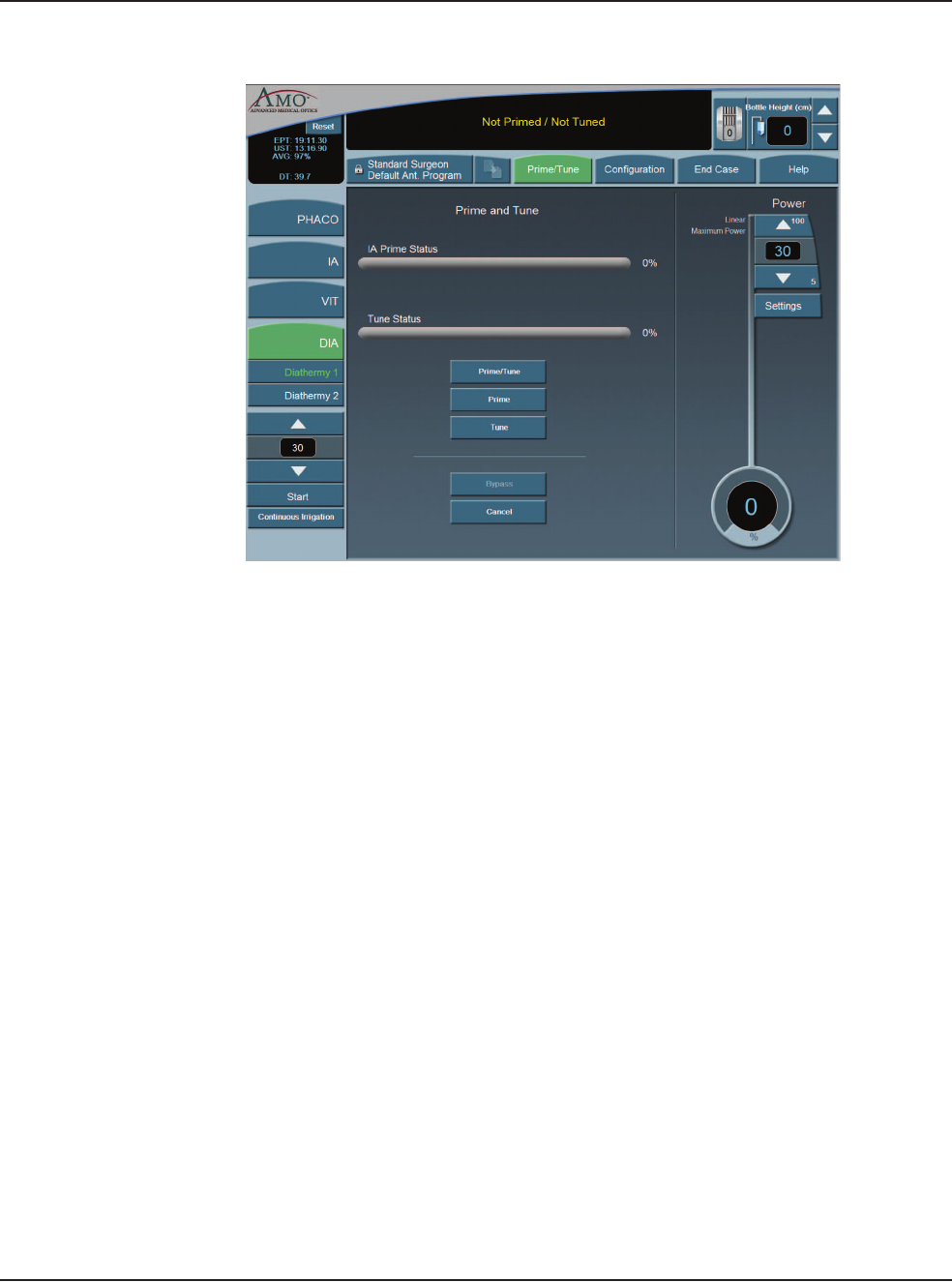
5 • Anterior Segment Surgery Operating Modes
WHITESTAR SIGNATURE™ System Rx Only – Z370147 Rev. C 1008 5-3
Figure 5.2 – Prime/Tune in Diathermy Mode
Using Diathermy
To begin Diathermy:
1. On the left panel press DIA.
2. Press the desired DIA submode button (DIA 1 is selected by default).
The elapsed DIA time is displayed in the upper left corner as “DT”.
In the main panel, you can increase or decrease the power by pressing the
diathermy Power Up or Down arrows. If Linear power is selected, you can use the
footpedal to increase or decrease the power up to the maximum preset value.
To change the power delivery, press Settings. The Settings window opens. Set the
power delivery to Panel, Linear or Burst. Linear delivery is the default.
•Panel – Diathermy power is delivered consistently at the power level (%)
selected and indicated on the screen as Panel Maximum Power.
•Linear – Diathermy power is delivered from 5% to the maximum selected value
(Maximum Power) as the footpedal is pressed.
•Burst – Diathermy is delivered as a single 150 ms pulse, at the selected power,
as the footpedal is pressed.
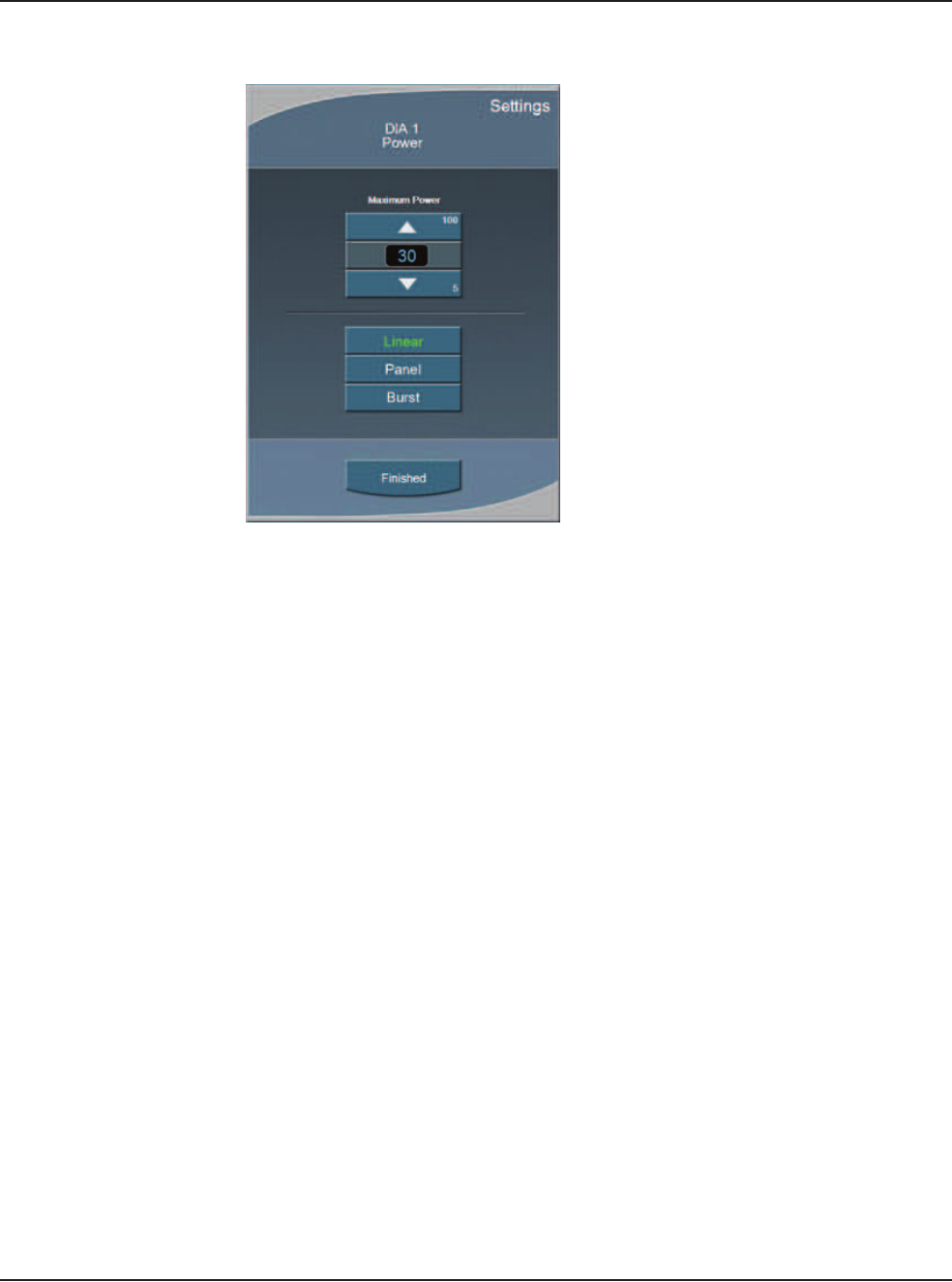
5 • Anterior Segment Surgery Operating Modes
WHITESTAR SIGNATURE™ System Rx Only – Z370147 Rev. C 1008 5-4
Figure 5.3 – Diathermy Power Submode
To set the submode parameters:
1. Make the desired settings to the DIA 1 values
2. Press the DIA 2 button to set the parameter values.
3. Change the parameter values for DIA 2.
4. After the submode (Program submode DIA 1, DIA 2) parameters are set, you
can press another mode button in the left panel to program PHACO, IA, or
VIT modes.
5. To access the SAVE buttons and save the submode settings, press End Case in
the top panel if no other changes are needed and save the settings.
Irrigation/Aspiration
Aspiration flow is necessary to remove the emulsified cataract material from the
eye. An irrigation supply is necessary to replace fluid removed by aspiration of
cortical material and fluid lost to leakage from the incision.
This fluid balance maintains the anterior chamber during surgery. Irrigation is
controlled by gravity.
The flow rate of irrigation solution through the irrigation sleeve on the phaco tip is
determined by the height of the drip chamber (head pressure). The drip chamber
hangs from the bottle on the Programmable IV Pole. AMO recommends that at the
start of a procedure, the irrigation solution level in the drip chamber be located
approximately 65–70 cm above the patient's eye level. To increase irrigation
pressure, the IV bottle is raised. To decrease pressure, the bottle is lowered.
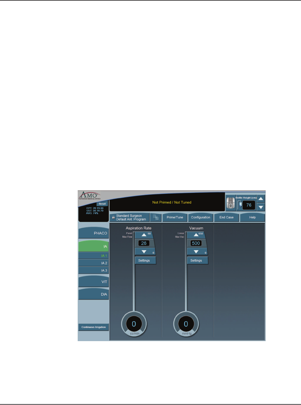
5 • Anterior Segment Surgery Operating Modes
WHITESTAR SIGNATURE™ System Rx Only – Z370147 Rev. C 1008 5-5
The irrigation tubing runs through the tubing cassette and irrigation is controlled by
the footpedal. When the footpedal is pressed, the pinch valve is opened and the
irrigation fluid flows. Irrigation runs in footpedal Positions 1, 2 and 3.
To program IA submodes:
1. On the left panel, press IA.
2. Select the desired IA submode. IA 1 is selected by default.
3. Press the Up or Down arrows in the control panels on the main panel to
increase or decrease Aspiration Rate or Vacuum.
Note: If the Venturi pump is On, only the Vacuum Settings are shown. To turn
the Venturi pump setting on, use the IA Submode Configuration screen.
4. Press the Settings button in the control panels on the main panel to change
Aspiration Mode or Vacuum Mode,
5. Press Finished to close the Settings window.
6. After all the submodes are programmed, select another mode.
7. If no other changes are needed press End Case to access the SAVE buttons and
save the settings.
Figure 5.4 – Irrigation/Aspiration Mode
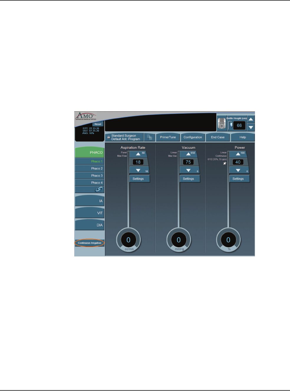
5 • Anterior Segment Surgery Operating Modes
WHITESTAR SIGNATURE™ System Rx Only – Z370147 Rev. C 1008 5-6
Continuous Irrigation
Continuous Irrigation is designed for collection of balanced salt solution for use
during the case. This function opens the irrigation valve for fluid collection
independent of the footpedal or prime cycle.
To activate Continuous Irrigation:
1. On the side panel, press the Continuous Irrigation button. This opens the
valve and starts the flow of irrigation fluid.
2. Press Continuous Irrigation again to deactivate the continuous irrigation.
Figure 5.5 – Continuous Irrigation
Phacoemulsification
The purpose of phacoemulsification or PHACO is to emulsify the lens material.
The phacoemulsification (phaco) handpiece provides ultrasonic energy, irrigation
and aspiration simultaneously so that the lens material is extracted as it is
emulsified. The phacoemulsification handpiece has a hollow needle that vibrates
longitudinally at an ultrasonic frequency or a blend of longitudinal and transversal,
if using the Ellips™. The rapid movement of the needle and the resulting
cavitational energy disintegrates the cataract on contact. The debris is removed by
suction through the hollow needle (aspiration). The resulting loss in volume of the
anterior chamber is compensated by incoming balanced salt solution (irrigation).
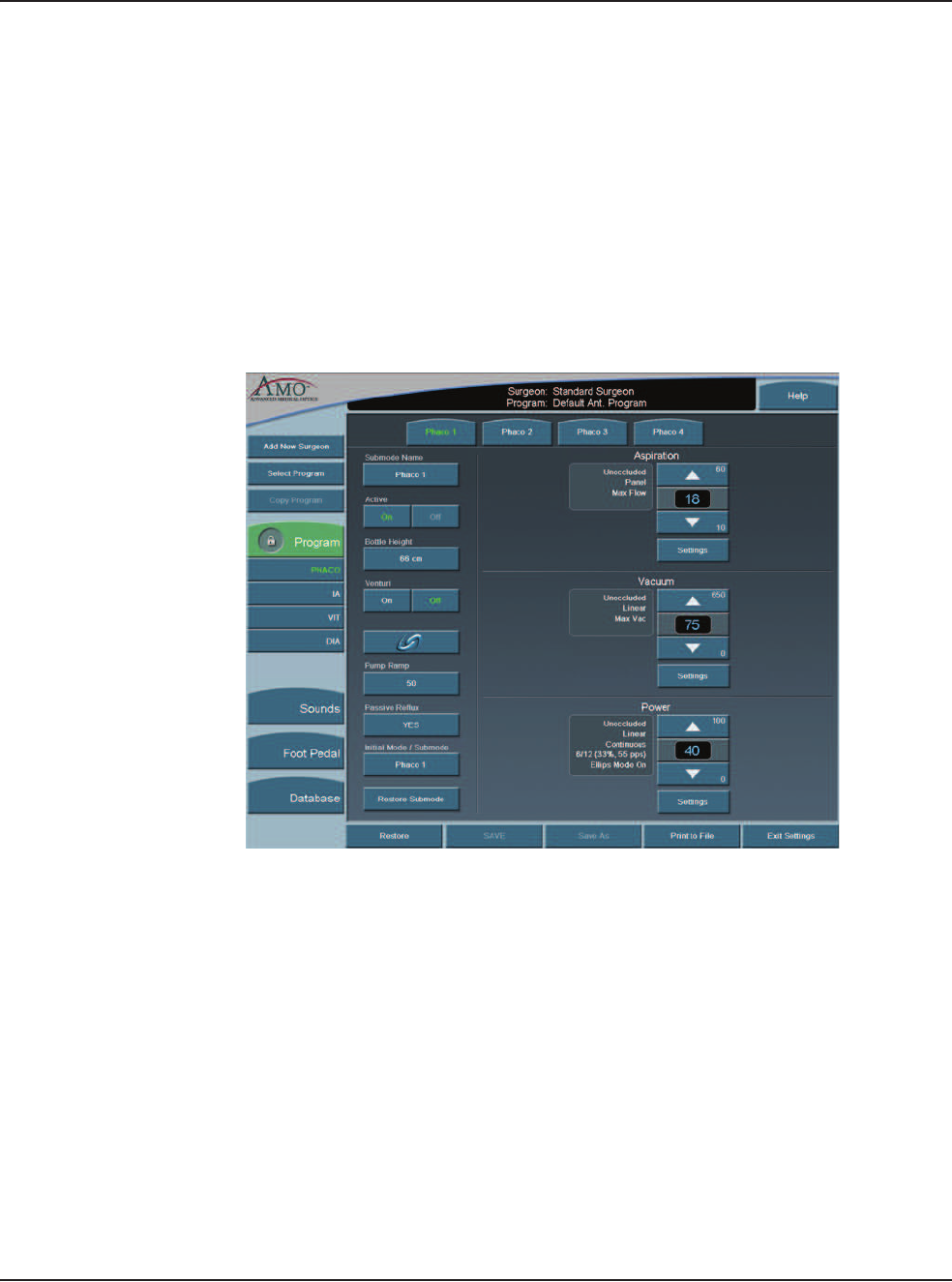
5 • Anterior Segment Surgery Operating Modes
WHITESTAR SIGNATURE™ System Rx Only – Z370147 Rev. C 1008 5-7
PHACO Submodes
There are four PHACO submodes. Within each submode, there are programmable
parameters for Unoccluded Phaco, and Occluded Phaco, and CASE settings.
Phaco Power is a combination of stroke length, frequency and handpiece
efficiency. A preset power setting of 30% using linear control allows you the
ultimate control during phaco. Adjustments to phaco power depend on factors that
include nuclear density, your preferences and your experience.
Phacoemulsification mode lets you set four submodes with different settings. You
can adjust the individual parameters of each submode.
Figure 5.6 – PHACO Submodes
For each PHACO submode, you can change the following settings:
• Aspiration Rate
• Vacuum
• Power
Before phacoemulsification, you must complete the steps to verify the Irrigation
and Aspiration balance, as recommended in the Irrigation/Aspiration section in this
chapter.
5 • Anterior Segment Surgery Operating Modes
WHITESTAR SIGNATURE™ System Rx Only – Z370147 Rev. C 1008 5-8
Using PHACO
1. Press PHACO.
2. Press Phaco 1, Phaco 2, Phaco 3, or Phaco 4 to select the submode. The main
panel shows all of the settings for Aspiration Rate, Vacuum and Power. Each
submode has different default settings.
3. Press the footpedal to activate phacoemulsification. The Aspiration Rate,
Vacuum and Power control panels indicate the associated levels throughout the
procedure. The Footpedal icon in the upper right corner of the screen shows the
position of the footpedal.
How to Program PHACO
1. Press the PHACO button.
2. Press the desired submode button. Phaco 1 is selected by default.
Note: You can set your Initial Mode/Submode on the Phaco Configuration screen.
The Initial Mode/Submode is then your default setting. (Refer to Program
Configuration, in this chapter.)
3. In the control panels in the main panel, click the Up or Down arrows to
increase or decrease Aspiration Rate, Vacuum, or Power.
Note: If the Venturi pump is On, only the Vacuum and Power Settings are shown.
CASE is not accessible when the Venturi pump is On.
4. Repeat for each submode you want to program.
5. If OCCLUSION MODE™ Phaco or CASE is desired, press in the
left column to activate the FUSION™ Mode screen. When OCCLUSION
MODE™ Phaco is active, the On button is green.
Figure 5.7 – Fusion™ Fluidics Screen
5 • Anterior Segment Surgery Operating Modes
WHITESTAR SIGNATURE™ System Rx Only – Z370147 Rev. C 1008 5-9
If you use CASE or OCCLUSION MODE™ Phaco, you can set different values
for both Occlusion Threshold and Max Vacuum. Refer to Fusion™ Fluidics Phaco
for programming CASE and OCCLUSION MODE™ Phaco modes.
After all four PHACO submodes are programmed; press a mode button to select
another mode.
If no other changes are needed press End Case to access the SAVE buttons and
save the settings.
WHITESTAR® Technology
The WHITESTAR® Technology can be applied in any phaco power delivery
mode. This technology is an advanced phacoemulsification power mode that
delivers finely modulated pulses of energy interrupted by extremely brief cooling
periods. This technology is available in Linear or Panel mode. When the
WHITESTAR® delivery mode is turned on, either or appears on the touch
screen, along with the WHITESTAR® Duty Cycle.
Figure 5.8 – WHITESTAR® Technology
WHITESTAR® Duty Cycles are expressed as Pulse Time On/Pulse Time Off, to
achieve a desired Duty Cycle. For example, the Duty Cycle setting 6/12 means that the
pulse time On is 6 ms, and the pulse time Off is 12 ms, resulting in a 33% duty cycle.
5 • Anterior Segment Surgery Operating Modes
WHITESTAR SIGNATURE™ System Rx Only – Z370147 Rev. C 1008 5-10
Table 5.1 – WHITESTAR® Technology Parameter Settings
Figure 5.9 – Duty Cycle
When the Variable WHITESTAR® Technology is used, different duty cycles are
applied as the footpedal moves through the power delivery zone. The zone is
divided into four equal size quadrants, and a different duty cycle can be applied in
each quadrant.
Setting Pulse On
Time (ms)
Pulse Off
Time (ms)
Duty Cycle Pulse Rate
(pps)
6/12 6 12 33% 55
4/8 4 8 33% 83
6/4 6 4 60% 100
6/8 6 8 43% 71
8/4 8 4 67% 83
4/24 4 24 14% 35
6/28 6 28 18% 29
6/24 6 24 20% 33
8/24 8 24 25% 31
6/18 6 18 25% 41
5 • Anterior Segment Surgery Operating Modes
WHITESTAR SIGNATURE™ System Rx Only – Z370147 Rev. C 1008 5-11
Figure 5.10 – Variable WHITESTAR® Technology Footpedal Positions and
Duty Cycles
The WHITESTAR SIGNATURE™ System maintains duty cycles to be used with
Variable WHITESTAR® – Variable WS. Variable WS contains the four duty
cycles that are used in the different quadrants. You can also use the sliding
adjustments to create Custom WHITESTAR® duty cycles for WS.
1. Footpedal Position 3
2. WHITESTAR® Duty Cycle
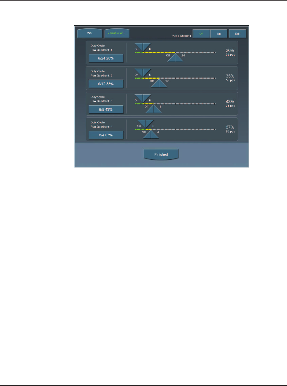
5 • Anterior Segment Surgery Operating Modes
WHITESTAR SIGNATURE™ System Rx Only – Z370147 Rev. C 1008 5-12
Figure 5.11 – Duty Cycles for Variable WS
WHITESTAR® ICE Technology Pulse Shaping
The WHITESTAR® ICE Technology was the next micro-pulse advance in
phacoemulsification technology, which combined modulated ultrasonic power
(pulse shaping) with vacuum control through the application of the Chamber
Stabilization Environment (CASE).
This pulse shaping technology modified the standard “square” wave pulse, by
increasing the amplitude of the first millisecond of the On Time “kick”, and then
setting the remaining part of the On Time to the standard power setting. This is
repeated for each On Time period, resulting in increased control and efficiency in
phacoemulsification.
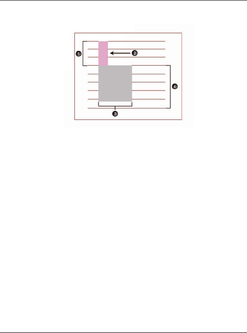
5 • Anterior Segment Surgery Operating Modes
WHITESTAR SIGNATURE™ System Rx Only – Z370147 Rev. C 1008 5-13
Figure 5.12 – WHITESTAR® ICE Technology Pulse Shaping
To access the WHITESTAR® ICE Technology settings:
1. Press the Power Settings button.
2. Press the WHITESTAR mode button.
3. Press On for Pulse Shaping.
4. Press Edit to access the Pulse Shaping parameter settings.
5. Press Finished to close the screen. Continue to press Finished to return to the
main screen.
1. Kick Amplitude 3. Burst Width
2. 1 Millisecond Kick 4. Phaco Power Level
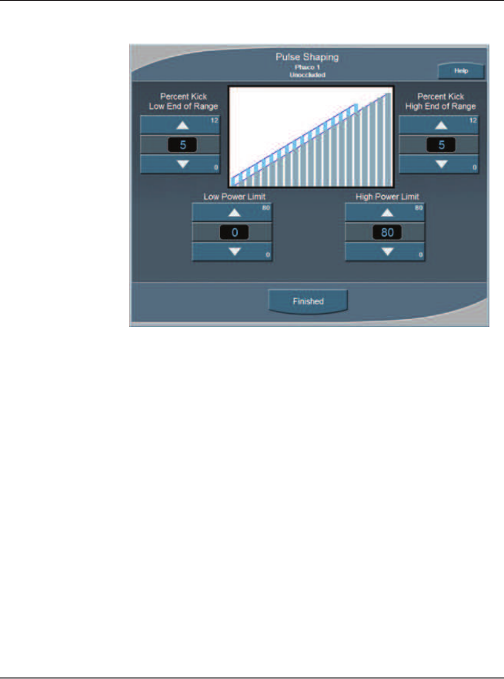
5 • Anterior Segment Surgery Operating Modes
WHITESTAR SIGNATURE™ System Rx Only – Z370147 Rev. C 1008 5-14
Figure 5.13 – Pulse Shaping Screen
There are four settings for WHITESTAR® ICE Pulse Shaping:
• Low Power Limit
• High Power Limit
• Percent Kick Low End of Range
• Percent Kick High End of Range
The Low and High Power Limit settings define the range over which pulse shaping
is applied. When the applied Phaco Power is outside of these limits, no pulse
shaping is applied.
The Percent Kick settings determine the amplitude, or amount of Phaco Power
“kick” that is applied in the first millisecond of Phaco Power application, either in
the low end or the high end of the power range. As the Phaco power increases from
the Low Power limit to the High Power Limit, the percentage of kick is interpolated
for the power ranges in between the two limits.
As an example, if a small kick setting is established for the Low End of the range
and a large kick setting is established for the High End of the range, the kick
percentage gradually increases as the Phaco Power increases. When the Percent
Kick at the Low End is the same as the High End, then the kick remains constant
throughout the Low to High range.
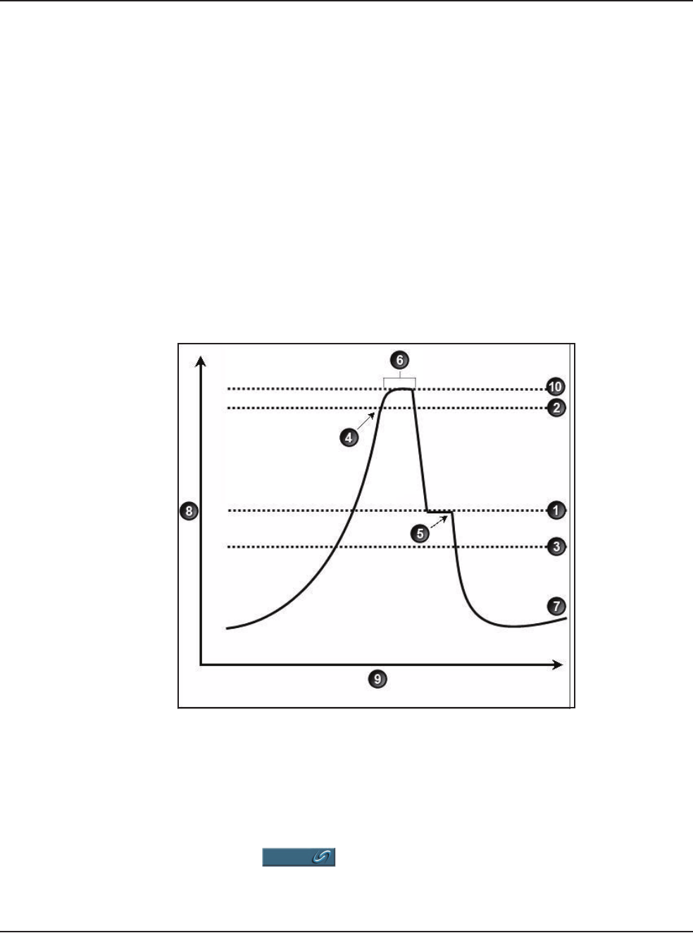
5 • Anterior Segment Surgery Operating Modes
WHITESTAR SIGNATURE™ System Rx Only – Z370147 Rev. C 1008 5-15
Fusion™ Fluidics
Phaco
Fusion™ Fluidics Phaco is an intelligent vacuum monitoring system used to
regulate the maximum allowable vacuum that is experienced following an
occlusion of the phaco tip. When the phaco tip becomes occluded, the vacuum
rises. Clearing of the occlusion while the vacuum is at a high level can cause a post-
occlusion surge. With CASE enabled, the System monitors the actual vacuum
levels and when the vacuum exceeds a specific threshold for a specified duration,
the System automatically adjusts the maximum allowable vacuum setting to a
lower predefined CASE maximum vacuum level. When the occlusion is cleared,
the System is automatically restored to the original programmed maximum vacuum
setting. It is possible to have a different maximum vacuum setting when the needle
is occluded than when the needle is not occluded.
The power modulation of the phaco handpiece can be programmed to automatically
change when the phaco tip changes from an unoccluded condition to an occluded
condition.
Figure 5.14 – Fusion™ Fluidics Phaco
The CASE screen shows the settings as a graph. To access the OCCLUSION
MODE™ Phaco and CASE settings:
1. Press the button from the PHACO mode screen.
1. CASE Vacuum 6. Up Time
2. Upper Threshold 7. Vacuum Level
3. Lower Threshold 8. Vacuum.
4. Vacuum Level crosses Upper Threshold. 9. Time.
5. Phaco activated. 10. Max Vac
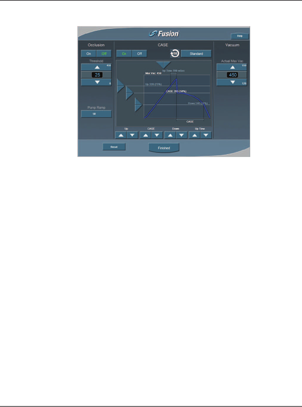
5 • Anterior Segment Surgery Operating Modes
WHITESTAR SIGNATURE™ System Rx Only – Z370147 Rev. C 1008 5-16
Figure 5.15 – Fusion™ Fluidics Phaco Screen
2. Press the On button to turn CASE mode on.
Note: If the Venturi pump option is On, you cannot access the Fusion™ Fluidics
screen. There is no Occlusion Mode or CASE Mode with Venturi.
3. Use the Up and Down arrows at the bottom of the screen to adjust the:
•CASE Vacuum (CASE) – This is the optimum occlusion vacuum setting
•Upper Threshold (Up) – This is the maximum threshold vacuum setting,
which is maintained for the amount of time defined by the Up Time
Threshold.
•Lower Threshold (Down) – After the occlusion is cleared, the vacuum is
reduced to the lower vacuum threshold setting to allow the occlusion to be
safely cleared, and then gradually returned to the previous levels.
4. Use the Right and Left arrows in the graphic to change the Up Time
Threshold. The Up Time Threshold is the maximum time that the maximum
threshold vacuum is maintained.
5. Press Finished to close the screen
Use the Fusion™ Fluidics screen to turn OCCLUSION MODE™ Phaco Off or On.
When OCCLUSION MODE™ Phaco is On, the main PHACO operating screen
provides for alternative Aspiration, Vacuum and Phaco Power settings that are used
when an occlusion is detected.
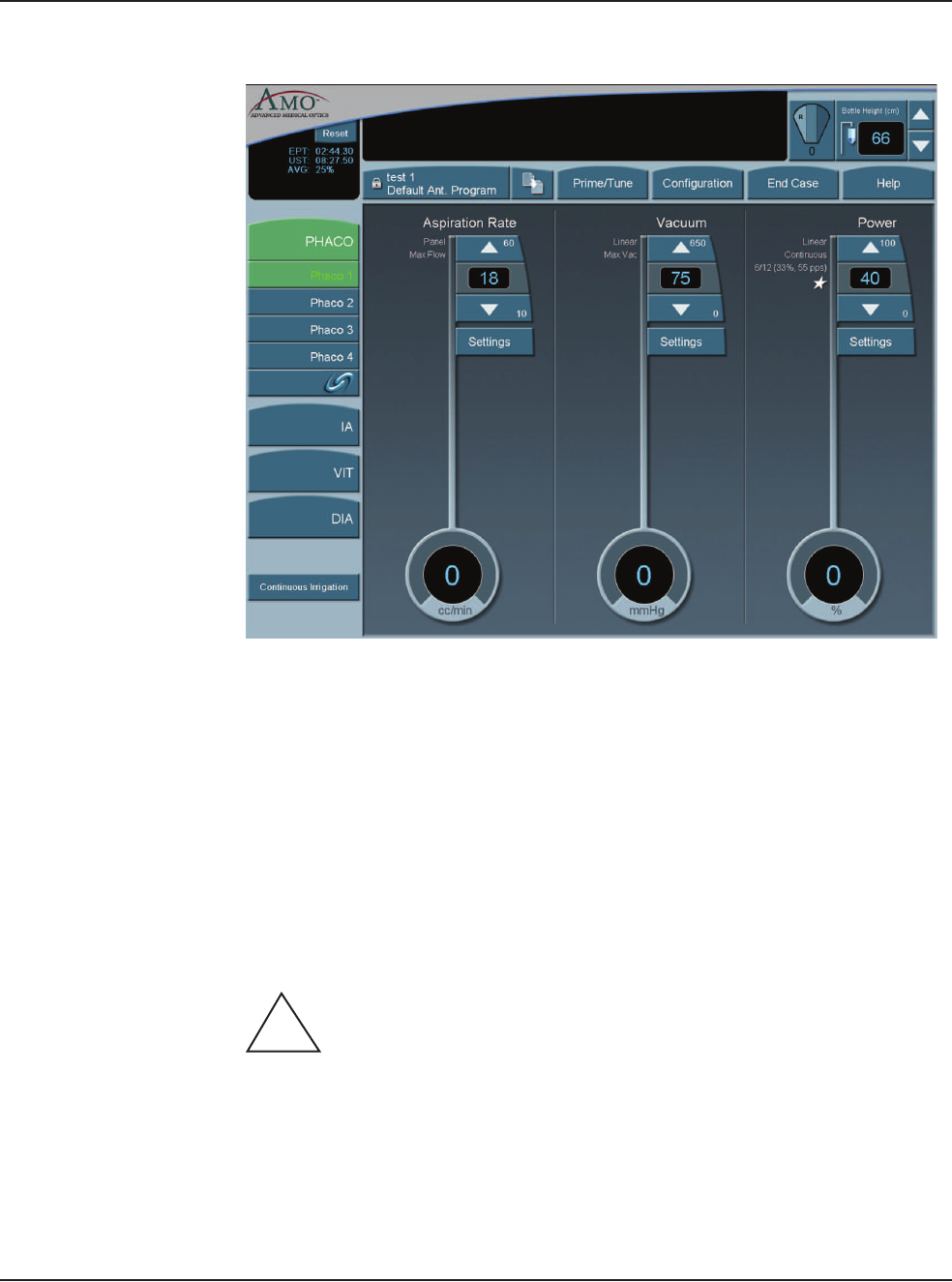
5 • Anterior Segment Surgery Operating Modes
WHITESTAR SIGNATURE™ System Rx Only – Z370147 Rev. C 1008 5-17
Figure 5.16 – PHACO Screen
Vitrectomy
The WHITESTAR SIGNATURE™ System uses a pneumatic guillotine vitrectomy
cutter. The handpieces are designed for cutting vitreous during anterior segment
surgery and operate in conjunction with the Irrigation/Aspiration mode. The cutting
speed can be changed on the touch screen. There are four adjustments related to the
Vitrectomy mode:
• Aspiration Rate
• Vacuum
• Cut Rate
• Footpedal
CAUTION: THE PHACO HANDPIECE AND VITRECTOMY
CUTTER MUST NEVER BE ACTIVATED WITH THE TIPS IN THE AIR.
EXPOSING THE TIP TO AIR DRASTICALLY REDUCES THE USEFUL LIFE
OF THE HANDPIECE. IF POWER IS TO BE INTRODUCED TO THE PHACO
HANDPIECE OR VITRECTOMY CUTTER, THE TIPS MUST BE IN A TEST
CHAMBER FILLED WITH A BALANCED SALT SOLUTION, IN A
CONTAINER OF BALANCED SALT SOLUTION OR IN THE PATIENT’S
EYE.
!
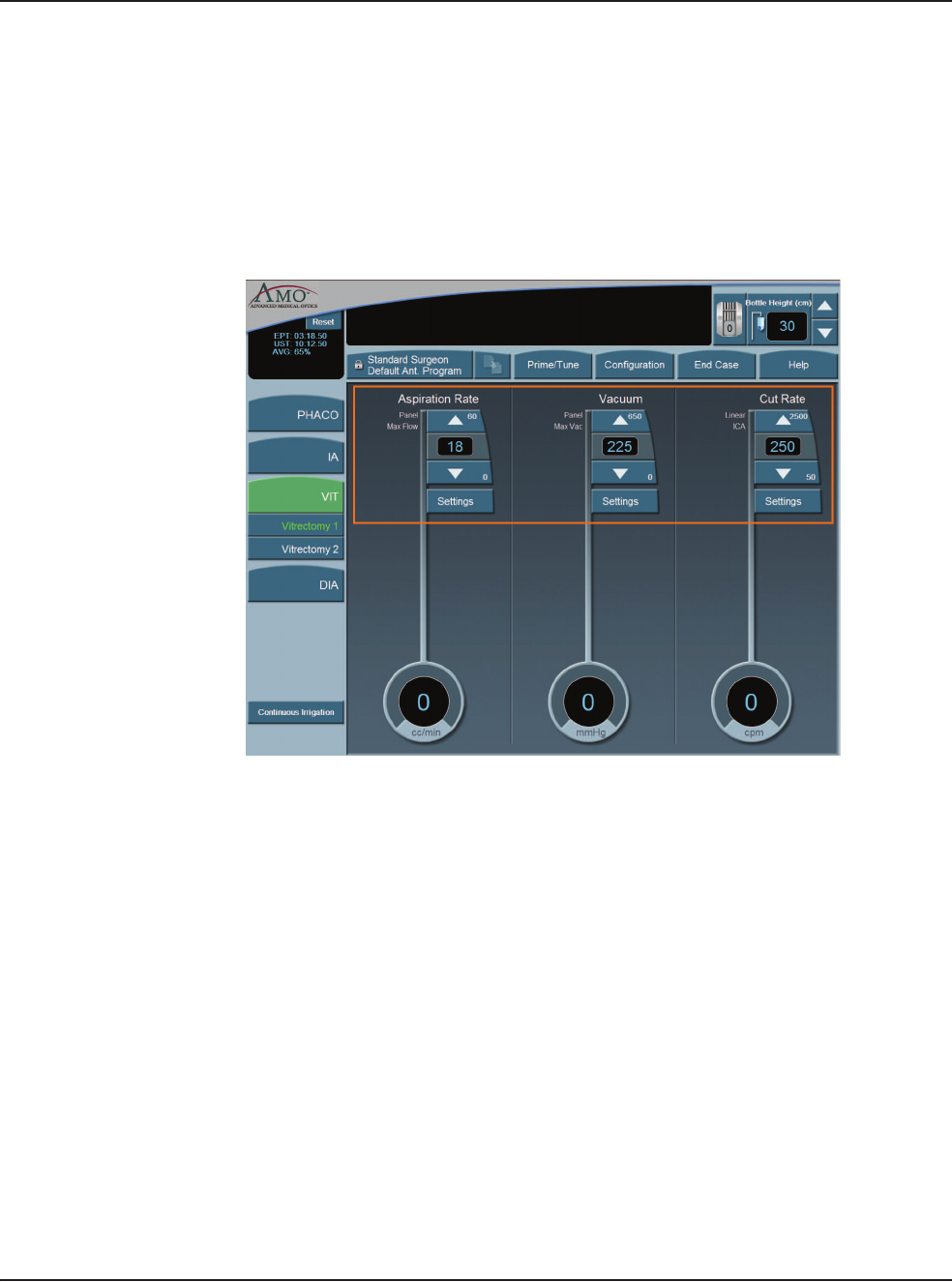
5 • Anterior Segment Surgery Operating Modes
WHITESTAR SIGNATURE™ System Rx Only – Z370147 Rev. C 1008 5-18
Using Vitrectomy
In the left panel, press VIT 1 or VIT 2 to select a submode. VIT 1 is selected by
default.
Note: Each time you select the vitrectomy mode you are prompted to prime the
vitrectomy handpiece. Refer to Chapter 4, Equipment Operation, Priming
for Vitrectomy for detailed information.
Figure 5.17 – Vitrectomy Mode Screen
1. In the main panel, press the Up or Down arrows to increase or decrease the
Aspiration Rate, Vacuum, or Cut Rate.
Note: If the Venturi pump is On, only the Vacuum and Cut Rate Settings are
shown.
2. To program the footpedal, go to Configuration, Surgeons and Programs,
Foot Pedal, Configuration, VIT.
3. Select a Submode to program.
4. Edit the footpedal settings as needed.
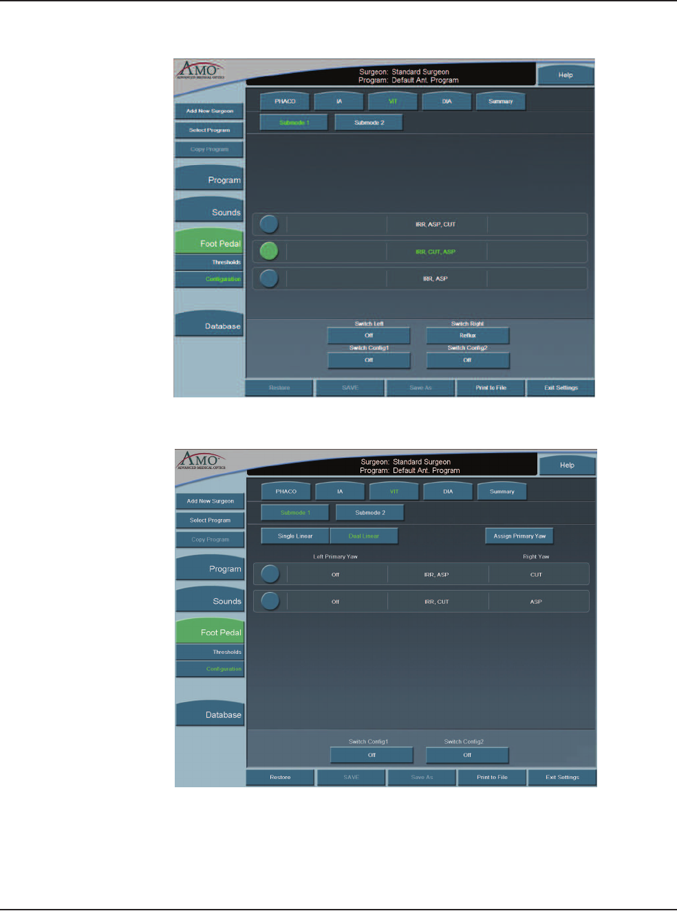
5 • Anterior Segment Surgery Operating Modes
WHITESTAR SIGNATURE™ System Rx Only – Z370147 Rev. C 1008 5-19
Figure 5.18 – Single Linear Foot Pedal Settings Screen
Figure 5.19 – Dual Linear Foot Pedal Settings Screen
5. When finished, press Exit Settings.
6. If no other changes are needed, press End Case to access the SAVE buttons
and save the settings

5 • Anterior Segment Surgery Operating Modes
WHITESTAR SIGNATURE™ System Rx Only – Z370147 Rev. C 1008 5-20
Footpedal Vitrectomy Modes
The footpedal mode selection must be made for ICA, IAC, or Side vitrectomy
(VIT), which determines how the vitrectomy cutter is activated as the footpedal is
pressed from Positions 1 through 3. Use the left side switch to activate the cutter at
the panel rate for Side VIT only.
Table 5.2 Vitrectomy Single Linear Footpedal Modes
Table 5.3 Vitrectomy Advanced Control Pedal (Dual Linear) Modes
Footpedal
Positions
Vitrectomy Footpedal Modes
ICA IAC Side VIT
1 Irrigation Irrigation Irrigation
2 Irrigation/Cut Irrigation/
Aspiration
Irrigation/
Aspiration
3 Irrigation/Cut/
Aspiration
Irrigation/
Aspiration/Cut
Irrigation/
Aspiration
Footpedal
Positions
Vitrectomy Footpedal Modes
ICA IAC Side VIT
1 Irrigation Irrigation N/A
2 Irrigation/Cut Irrigation/
Aspiration
N/A
Yaw Aspiration Cut N/A
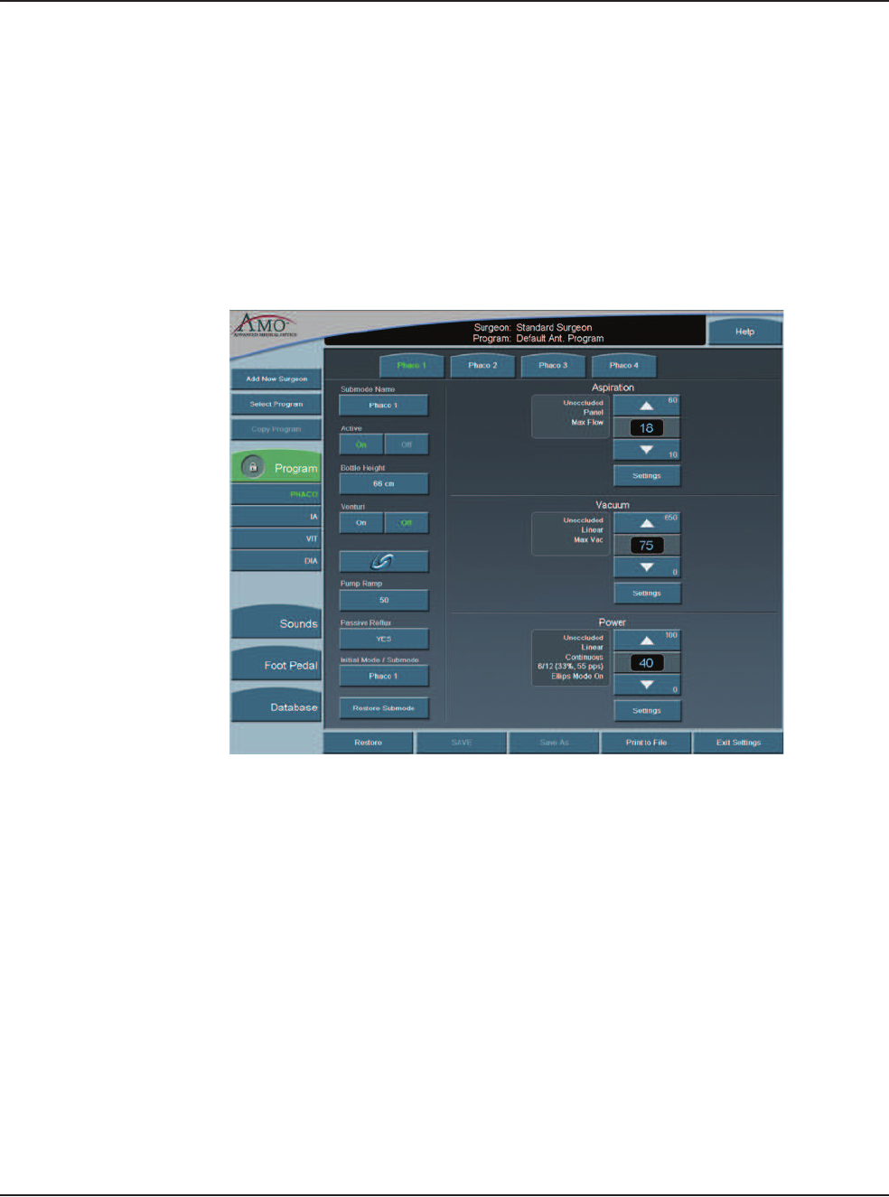
5 • Anterior Segment Surgery Operating Modes
WHITESTAR SIGNATURE™ System Rx Only – Z370147 Rev. C 1008 5-21
Programming the
Modes and Settings
Program Configuration
These programmed settings allow for the selection of operational features and
options pertinent to general operation for each mode and submode, the footpedal,
system sounds and the system database.
When the AMO Default Program is selected, all of the modes and submodes are
preset. Although these settings can be changed, they cannot be saved. Use the
defaults as a source to your system settings. All default settings can be easily
viewed on the Mode Configuration screens.
Figure 5.20 – PHACO Program Screen

5 • Anterior Segment Surgery Operating Modes
WHITESTAR SIGNATURE™ System Rx Only – Z370147 Rev. C 1008 5-22
AMO Default Setups
Sounds
Table 5.4 – WHITESTAR SIGNATURE™ System Default Settings
Specific to each surgeon program/setup
Sounds Available Settings AMO Default
Settings
High Vacuum On, Off On
Mode Change Off, Tone, Voice Voice On
Submode Change Off, Tone, Voice Voice On
Value Change On, Off Voice On
Activity Confirmation On, Off Voice On
Vacuum Off–10 6
Diathermy 5–10 6
Phaco Power Off–10 Off
Error 5–10 6
Irrigation Off-10 3
Key Press Off–10 6
Speech Off–10 6
CASE Activation 0–10 5
Master Volume 0–10 10
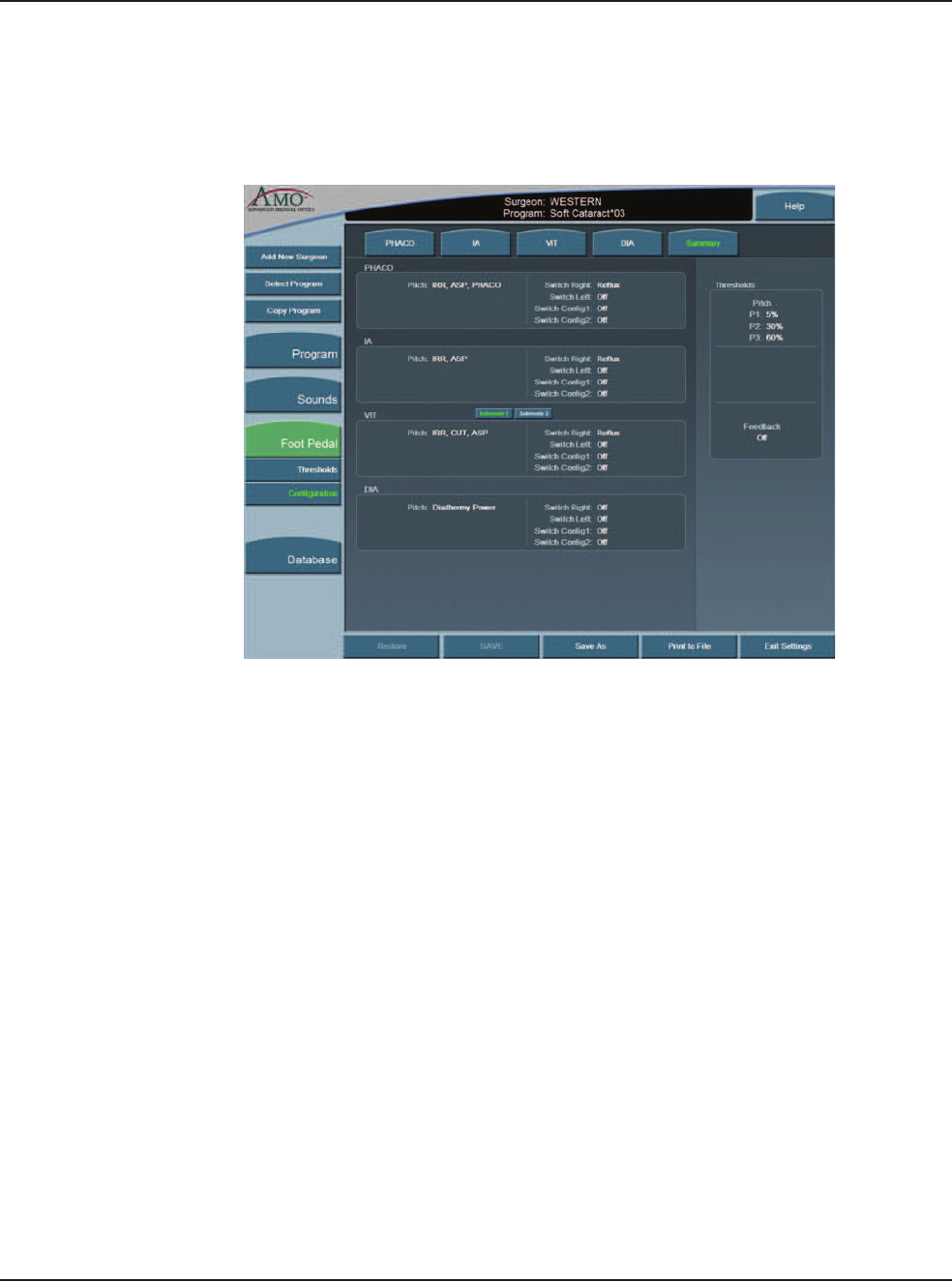
5 • Anterior Segment Surgery Operating Modes
WHITESTAR SIGNATURE™ System Rx Only – Z370147 Rev. C 1008 5-23
Footpedal – AMO Default Settings
The AMO Default footpedal settings for each operating mode are shown on the
System's Summary Screen.
Figure 5.21 – Single Linear Footpedal Summary Settings

5 • Anterior Segment Surgery Operating Modes
WHITESTAR SIGNATURE™ System Rx Only – Z370147 Rev. C 1008 5-24
Table 5.5 – Footpedal Threshold AMO Default Settings
*Switch Assignments
Table 5.6 – Diathermy – AMO Default Settings
Footpedal
Type
Parameter Available
Settings
AMO Default
Settings
Single Linear Pitch
Regions
1–100% P1=5%
P2=30%
P3=60%
Switch
Position
Switch1= *
Switch 2= *
Switch1=Off
Switch 2=Off
Right= *
Left= *
Right=Off
Left=Off
Feedback On, Off Off
Advanced
Control Pedal
(Dual Linear)
Primary Yaw * Reflux
Pitch Region 1-100% P1=5%
P2=30%
P3=60%
Yaw Position 5-100% Left=50%
Right=50%
Switch
Position
Switch1= *
Switch 2= *
Switch1=Off
Switch 2=Off
Yaw
Threshold
5% - 100% 5%
Feedback On, Off Off
Surgeon Program Up Surgeon Program Down Previous Major Mode Next Major Mode Previous Active Mode
Next Active Mode Previous Sub Mode Next Sub Mode Toggle SMC Record Bottle Up
Bottle Down Reflux Continuous Irrigation 1-Touch Up (Phaco
Only)
1-Touch Down (Phaco
Only)
Toggle Case (Phaco
Only)
Single Vit Cut
(Vitrectomy Only)
Parameter Available
Settings
AMO Default Settings
DIA 1 DIA 2
Max Power 5–100% 30% 30%
Power Delivery
Type
Linear, Burst,
Panel
Linear Burst
Initial Mode/
Submode
Any of the
Submode
Names
Phaco 1 Phaco 1

5 • Anterior Segment Surgery Operating Modes
WHITESTAR SIGNATURE™ System Rx Only – Z370147 Rev. C 1008 5-25
Table 5.7 – I/A – AMO Default Settings
Parameter Available
Settings
AMO Default Settings
IA1 IA2 IA3
Continuous
Irrigation
On, Off Off Off Off
Pump
Selection
Venturi
Peristaltic
Peristaltic Peristaltic Peristaltic
Bottle Height 0–104 cm
0–42 inches
76 cm
30 inches
50 cm
20 inches
50 cm
20 inches
Max Vacuum 0–650
mmHg
500
mmHg
500
mmHg
15 mmHg
Max
Aspiration/
Mode
(Peristaltic)
0–60 cc/min 26 cc/min
Panel
26 cc/min
Linear
6 cc/min
Panel
Peristaltic
Pump Ramp
Threshold
10–100% 80% 80% 80%
Venturi Pump On, Off Off Off Off
Passive Reflux
(Fusion™
Fluidics Pack)
Yes, No Yes Yes Yes
Passive Reflux
(Fusion™
Dual Pump
Pack)
Yes, No Yes Yes Yes
Initial Mode/
Submode
Any of the
Submode
Names
Phaco 1 Phaco 1 Phaco 1
Fluidic Mode Panel, Linear Panel
Aspiration
Linear
Vacuum
Linear
Aspiration
Panel
Vacuum
Panel
Aspiration
Linear
Vacuum

5 • Anterior Segment Surgery Operating Modes
WHITESTAR SIGNATURE™ System Rx Only – Z370147 Rev. C 1008 5-26
Table 5.8 – PHACO – AMO Default Settings
Parameter Available
Settings
AMO Default Settings
Phaco 1 Phaco 2 Phaco 3 Phaco 4
Bottle Height 0–104cm
0–42 inches
66 cm
26 inches
76 cm
30 inches
76 cm
30 inches
76 cm
30 inches
Continuous
Irrigation
On, Off Off Off Off Off
Pump Selection Venturi
Peristaltic
Peristaltic Peristaltic Peristaltic Peristaltic
Max Vacuum
Peristaltic
0–650 mmHg 75 mmHg 300 mmHg 400 mmHg 350 mmHg
Max Vacuum
Venturi
0-600 mmHg 75 mmHg 300 mmHg 400 mmHg 350 mmHg
Venturi Pump On, Off Off Off Off Off
Passive Reflux Yes, No
Fusion™
Fluidics Pack
Yes Yes Yes Yes
Fusion™ Dual
Pump Pack
Yes Yes Yes Yes
Initial Mode/
Submode
Any of the
Submode
Names
Phaco 1 Phaco 1 Phaco 1 Phaco 1
Max Flow/
Aspiration Rate,
Unoccluded
(Peristaltic)
10–60 cc/min 18 cc/min 24 cc/min 18 cc/min 24 cc/min
Fluidics Mode Panel, Linear Panel
Aspiration,
Linear
Vacuum
Panel
Aspiration,
Panel
Vacuum
Panel
Aspiration,
Linear
Vacuum
Panel
Aspiration,
Linear
Vacuum
Occlusion
Threshold
0–Max Vac. 25 mmHg 140 mmHg 60 mmHg 80 mmHg
OCCLUSION
MODETM Phaco
On, Off Off On On Off
CASE Mode On, Off Off Off On On
CASE Upper
Threshold.
0–Max Vac. 100 mmHg 250 mmHg 325 mmHg 300 mmHg
CASE Lower
Threshold.
0–Max Vac. 70 mmHg 175 mmHg 200 mmHg 200 mmHg
Up Time 0–2000 ms 300 ms 300 ms 300 ms 300 ms
CASE Vac 120–650
mmHg
85 mmHg 225 mmHg 250 mmHg 250 mmHg
CASE
One-Touch
-2, -1, STD,
+1, +2
STD STD STD STD
Peristaltic Pump
Ramp
10–100% 50% 60% 50% 70%
Power Delivery
Mode
(Unoccluded and
Occluded)
Continuous
Short Pulse
Long Pulse
Low Power
Pulse
High Power
Pulse
Single Burst
Multi-Burst
Continuous
Burst
Continuous Continuous Continuous Continuous
Short Pulse Rate 1–14 pps 6 pps 6 pps 6 pps 6 pps
Long Pulse Rate 1–6 pps 4 pps 4 pps 4 pps 4 pps

5 • Anterior Segment Surgery Operating Modes
WHITESTAR SIGNATURE™ System Rx Only – Z370147 Rev. C 1008 5-27
Table 5.9 – Vitrectomy – AMO Default Settings
WHITESTAR®
Technology
Duty Cycles
2–30 On Time
2–30 Off Time
Predefined: 6/
12, 4/8, 6/4, 6/
8, 8/4, 4/24, 6/
28, 6/24,
8/24, 6/18
6/12 (33%) 6/12 (33%) 6/12 (33%) 6/12 (33%)
Max Aspiration
Rate Occluded
10–60 cc/min 18 cc/min 28 cc/min 14 cc/min 24 cc/min
Max Phaco
Power Occluded
0–100% 40% 30% 10% 40%
Max Ellips™
Phaco Power
Occluded
On, Off Off Off Off Off
Max Phaco
Power
Unoccluded
0–100% 40% 20% 5% 30%
Max Ellips™
Phaco Power
Unoccluded
On, Off Off Off Off Off
Power Delivery
Type Occluded
Linear, Panel Linear Linear Linear Linear
Customized to Each Surgeon Program/Setup AMO Default Settings
Parameter Available
Settings
VIT 1 VIT 2
Bottle Height 0–104 cm
0–42 inches
30 cm
12 inches
30 cm
12 inches
Continuous Irrigation On, Off Off Off
Pump Selection Venturi
Peristaltic
Peristaltic Peristaltic
Max Vacuum/Mode
(Peristaltic)
0–650 mmHg
Panel, Linear
225 mmHg
Panel
225 mmHg
Panel
Max Aspiration Rate/
Mode
0–60 cc/min
Panel, Linear
18 cc/min
Panel
12 cc/min
Panel
Fluidic Mode Panel, Linear Panel
Aspiration
Panel
Vacuum
Panel
Aspiration
Panel
Vacuum
Cut Rate 50–2500 cpm 250 cpm 450 cpm
Footpedal Mode ICA, IAC ICA IAC
Pump Ramp
Threshold
10 - 100% 100% 100%
Venturi Pump On, Off Off Off
Parameter Available
Settings
AMO Default Settings

5 • Anterior Segment Surgery Operating Modes
WHITESTAR SIGNATURE™ System Rx Only – Z370147 Rev. C 1008 5-28
Aspiration Rate
The Aspiration Flow Rate is the speed at which material is removed from the eye
through the aspiration tubing. A pump provides the necessary aspiration flow to
withdraw fluid and lens material from the eye chamber through the handpiece.
With this aspiration flow system, the vacuum builds when the aspiration port is
blocked or occluded. The vacuum reduces as the occlusion clears.
You can adjust the rate in 1 cc increments from 0 to 60 cc per minute. You can also
choose Panel or Linear flow.
The flow rate decreases as the vacuum approaches maximum.
To adjust the flow rate:
1. On the Aspiration Rate control panel, press the Up or Down arrows to increase
or decrease the aspiration rate from 0 to 60 cc per minute.
2. Press the Settings button to select Linear or Panel aspiration flow.
The Settings panel appears.
3. Press the Linear or Panel button.
The Linear vacuum rate is linear with respect to the footpedal position. As the
footpedal is pressed through Position 2, the vacuum level travels between 0
mmHg and the maximum preset level as occlusions at the aspiration port occur.
The actual vacuum level is indicated by the vacuum progress shown on the
screen.
The Panel vacuum rate provides a continuous evacuation at the established
vacuum rate. The vacuum builds only when the footpedal is in Position 2 and
an occlusion in the aspiration port is created.
4. Press Finished to close the window.
Passive Reflux
(Fusion™ Fluidics
Pack)
Yes, No Yes Yes
Passive Reflux
(Fusion™ Dual
Pump Pack)
Yes, No Yes Yes
Initial Mode/
Submode
Any of the
Submode
Names
Phaco 1 Phaco 1
Customized to Each Surgeon Program/Setup AMO Default Settings
Parameter Available
Settings
VIT 1 VIT 2
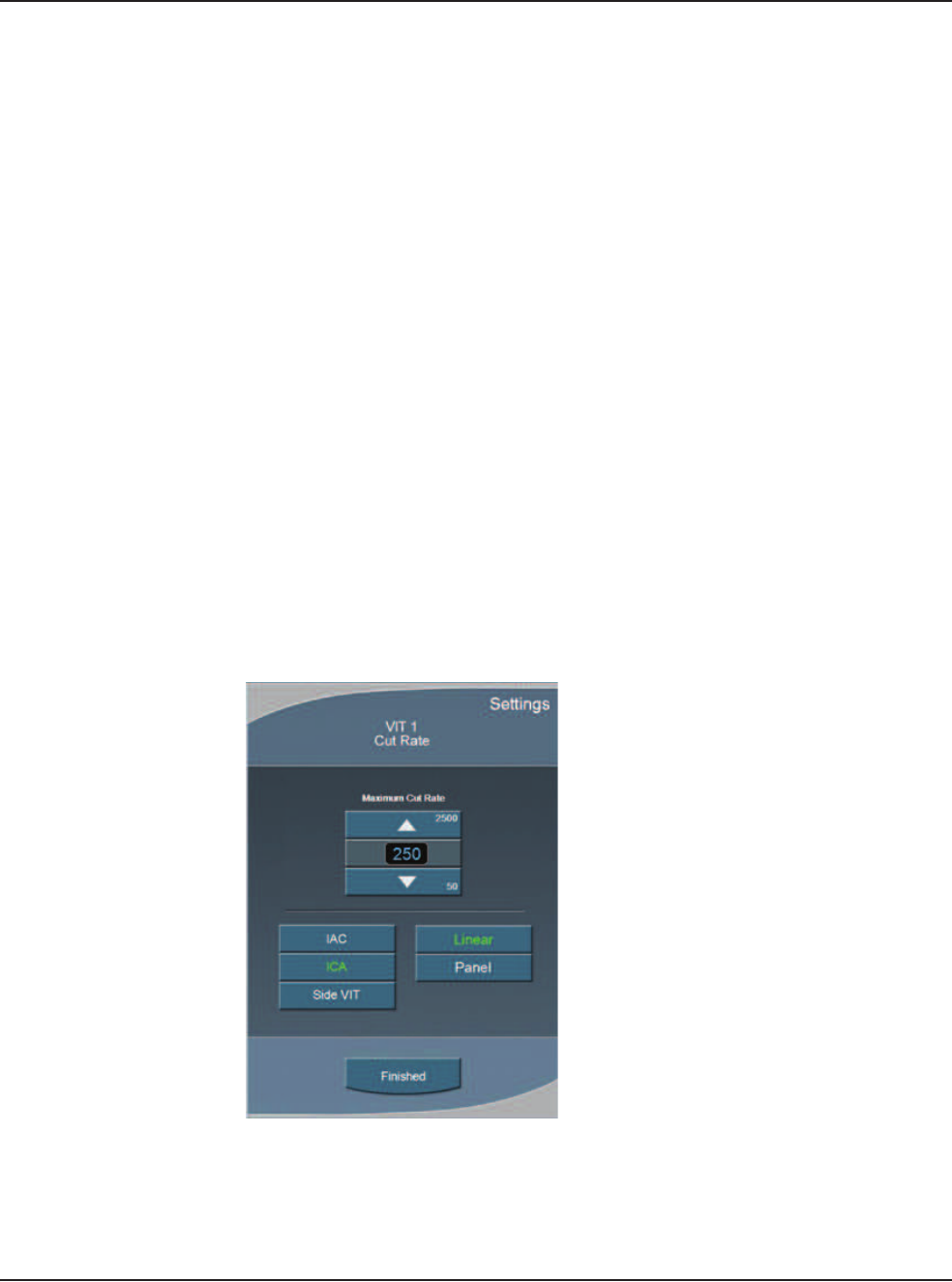
5 • Anterior Segment Surgery Operating Modes
WHITESTAR SIGNATURE™ System Rx Only – Z370147 Rev. C 1008 5-29
Vitrectomy Cutting Rates
Note: Each time you select the vitrectomy mode you are prompted to prime the
vitrectomy handpiece. Refer to Chapter 4, Equipment Operation, Priming
for Vitrectomy for detailed information.
You can vary the Vitrectomy Cut Rate of the vitrectomy cutter from 50-2500 CPM
(cuts per minute) in increments of 50 CPM between 100–1000, and 100 CPM
between 1000–2500 CPM.
Some surgeons prefer a higher rate, which allows the surgeon to perform the same
amount of cutting with smaller “bites” of vitreous. This minimizes motion and is
gentle on the tissue.
To adjust the cut rate
1. On the Cut Rate panel, press the Up or Down arrows to increase or decrease
the cut rate.
2. Press Settings to select either Linear or Panel cutting methods. The Settings
window opens.
Note: Side Vit is only available for use with a single linear foot pedal.
3. Press Linear or Panel button.
4. Press Finished to close the window.
Figure 5.22 – VIT Cut Rate
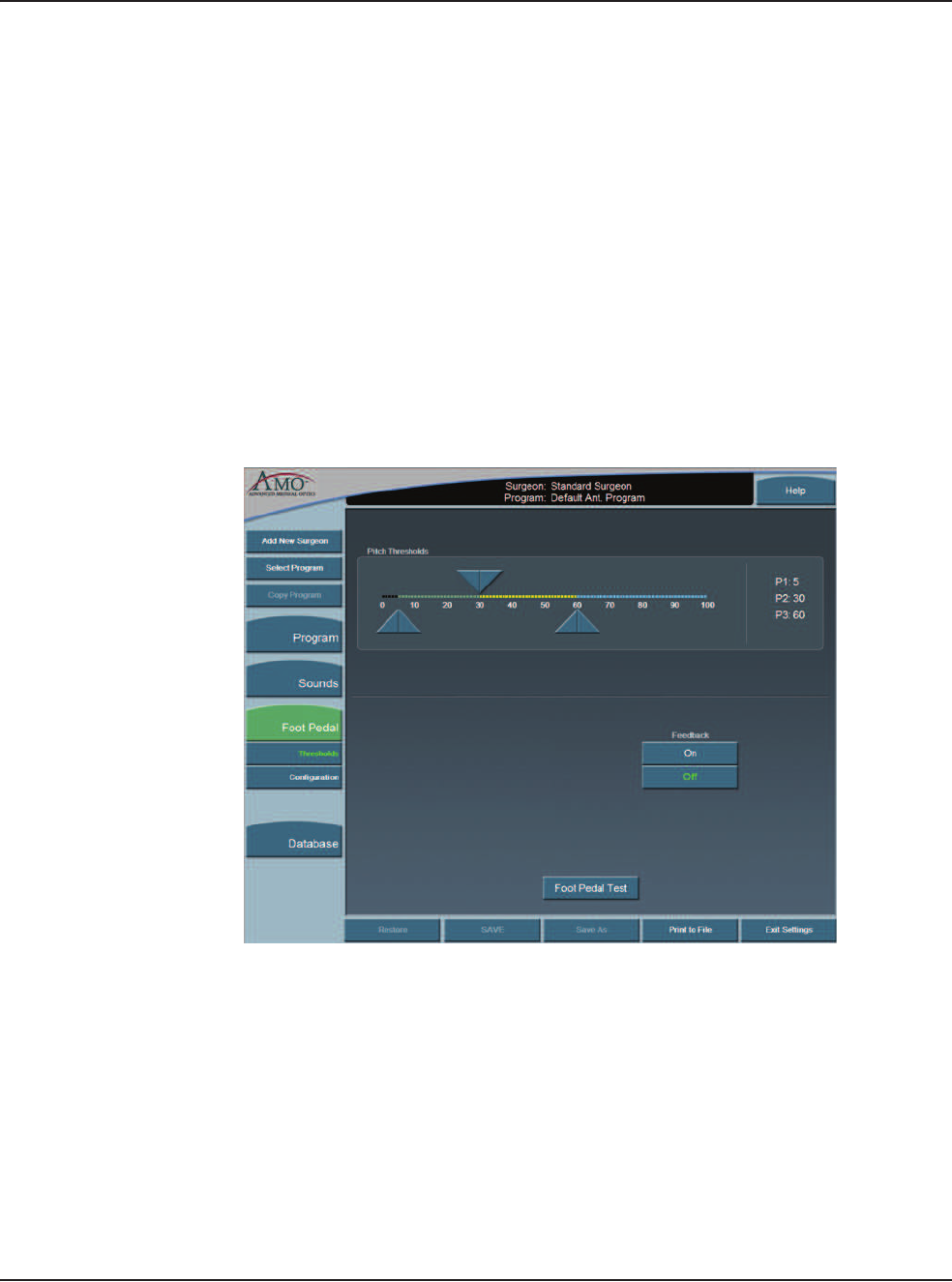
5 • Anterior Segment Surgery Operating Modes
WHITESTAR SIGNATURE™ System Rx Only – Z370147 Rev. C 1008 5-30
Footpedal Settings
The System accommodates multiple configurations for setting footpedal operation.
Each surgeon has one set of footpedal settings for all programs.
The Switch Assignment screen opens when you select On for any of the switches
on the Foot Pedal selection screens. The Switch Assignment screen allows you to
make a selection for that switch.
Footpedal Settings
From the top panel of any operating screen, press Configuration. The program
highlighted on the Main Menu is used.
1. Press Surgeons and Programs in the pop-up window.
2. In the side panel press Foot Pedal.
Figure 5.23 – Foot Pedal Pitch Thresholds - Single Linear
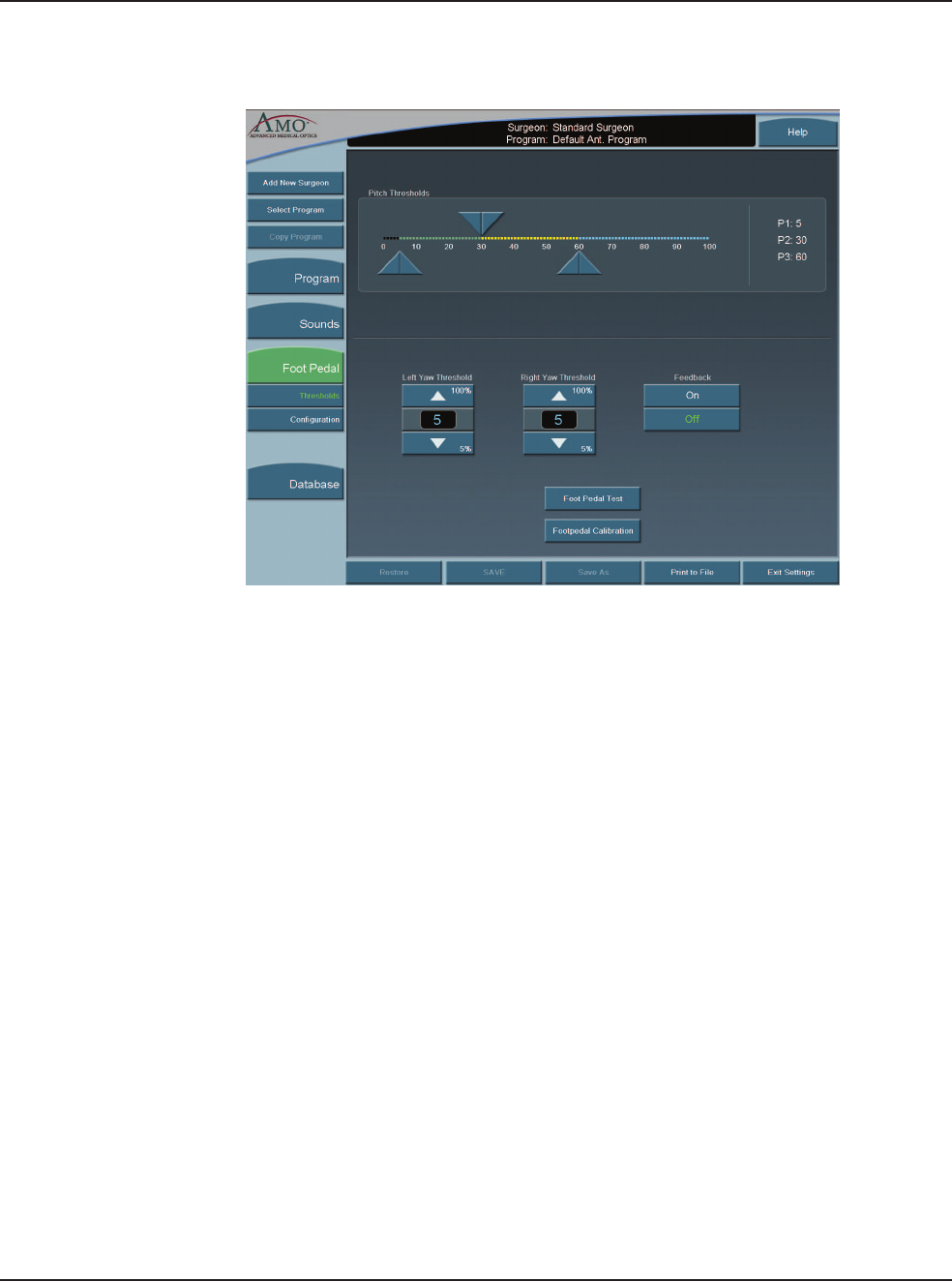
5 • Anterior Segment Surgery Operating Modes
WHITESTAR SIGNATURE™ System Rx Only – Z370147 Rev. C 1008 5-31
Figure 5.24 – Foot Pedal Pitch Thresholds - Advanced Control Pedal (Dual
Linear)
3. Adjust the Yaw Threshold percentage if the Advanced Control Pedal is used.
4. Adjust the Foot Pedal Pitch Threshold settings.
5. Turn the Foot Pedal Feedback On or Off. You can use the Foot Pedal Test
button to test your settings.
6. Press Configuration. The Foot Pedal Settings options are shown.
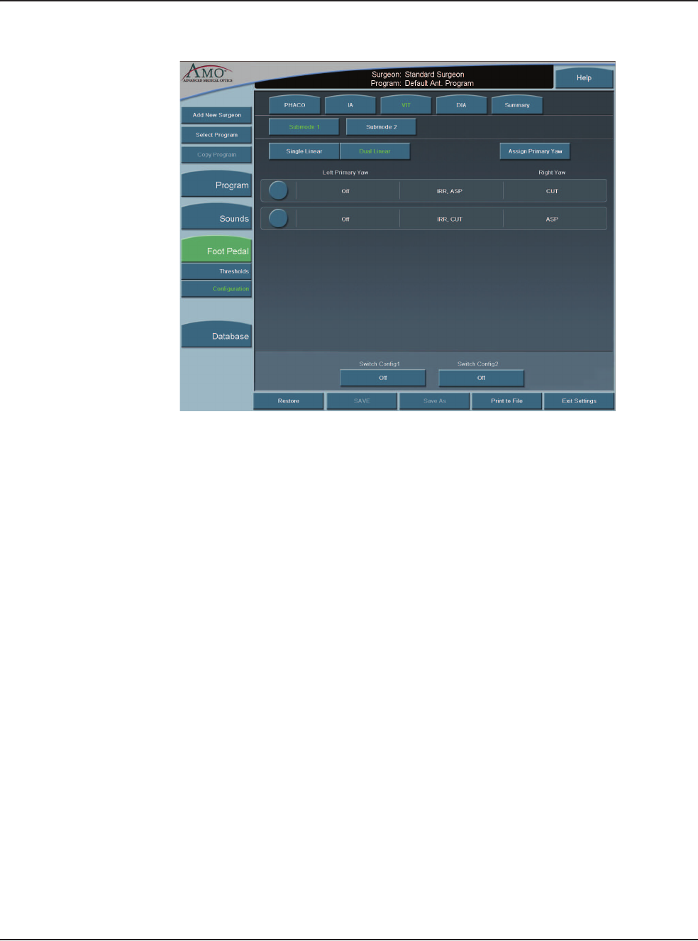
5 • Anterior Segment Surgery Operating Modes
WHITESTAR SIGNATURE™ System Rx Only – Z370147 Rev. C 1008 5-32
Figure 5.25 – VIT Foot Pedal Settings Advanced Control Pedal (Dual Linear)
7. Select the type of foot pedal.
8. Select the Primary Yaw. Each time you select the Assign Primary Yaw button,
the selection is changed from left-to-right or right-to-left.
9. Select the operating modes for that surgery using the top Mode tabs and
complete the footpedal setup for each mode (PHACO, IA, VIT, or DIA). The
footpedal settings are shown in the center of the screen. Select Summary to
view the footpedal settings for all of the modes.
10. Press each of the switches in any of the four modes. A pop-up window is shown
for each switch.
11. Select the Switch Assignment from the list.
Note: WHITESTAR Increment/Decrement is used to increase or decrease the
Duty Cycles during surgery.
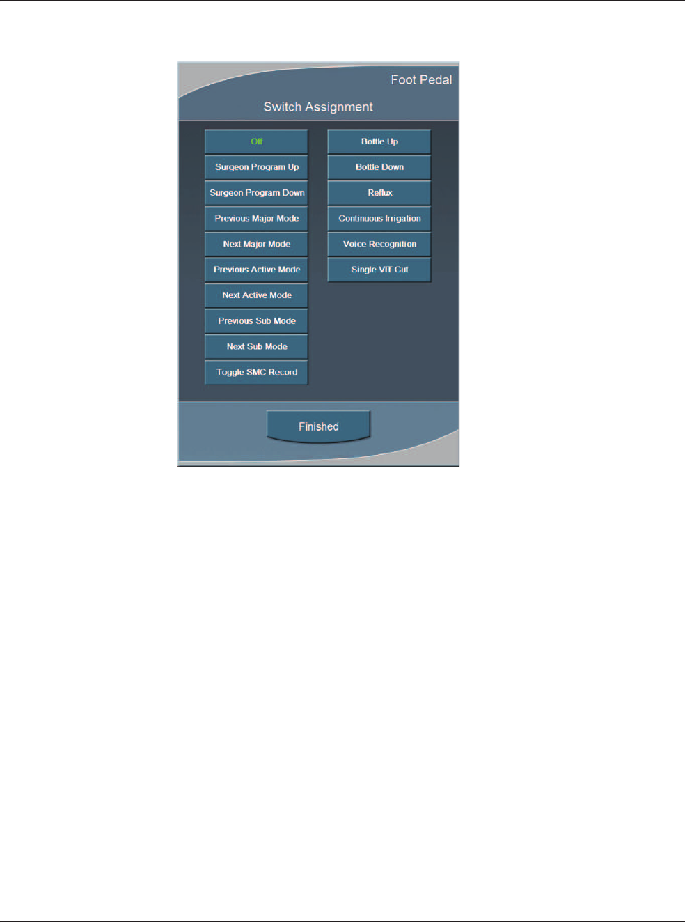
5 • Anterior Segment Surgery Operating Modes
WHITESTAR SIGNATURE™ System Rx Only – Z370147 Rev. C 1008 5-33
Figure 5.26 – Vitrectomy Switch Assignment Pop-up Window
12. Press Finished to close the window.
13. Press SAVE to retain the settings.
Note: If you entered Configuration while in an Operating mode, press Exit
Settings to return to the previous mode.

5 • Anterior Segment Surgery Operating Modes
WHITESTAR SIGNATURE™ System Rx Only – Z370147 Rev. C 1008 5-34
Vacuum
The vacuum is the force exerted on the aspirated fluid in the aspiration tubing. To
make sure you have fluidic balance while in phacoemulsification, you can adjust
the Max Vac from 0 to 650 mmHg (Peristaltic pump), as indicated on the Vacuum
panel.
1. To adjust the vacuum settings:
• To increase or decrease vacuum force, press the Up and Down arrows on the
Vacuum panel.
2. To select Linear or Panel flow, press Settings. The Vacuum Settings pop-up
window appears.
3. Press the Linear or Panel button.
4. Press Finished.
The Linear flow increases from the minimum (0 cc per min) to the maximum preset
flow rate as the surgeon presses the footpedal through Position 2. A higher flow
rate (as delivered from the footpedal) results in a quicker vacuum rise time. A
slower flow rate results in a slower vacuum rise time.
The Panel flow provides a constant evacuation at the preset flow rate when the
footpedal enters Position 2.
End Case
End Case is available in the top panel from any programming or surgical mode.
End Case allows you terminate the programming session or surgical case. If
changes were made to the program settings, you are prompted to SAVE the
settings.
Note: For ease of viewing, the EPT, Ellips EPT, UST and AVG times are shown
in a large font size on the End Case window. The Ellips EPT is shown only
when Ellips™ Technology is On.
Program
Note: SAVE, Save As, and Restore have the same functions on the Program
Configuration screens.
SAVE – Saves the changes to the existing Surgeon Name/Program.
Save As – Saves the program changes (made to an existing program) to a new
program name when you enter a program name.
Restore – Erases any program changes and resets the values back to the last saved
values.
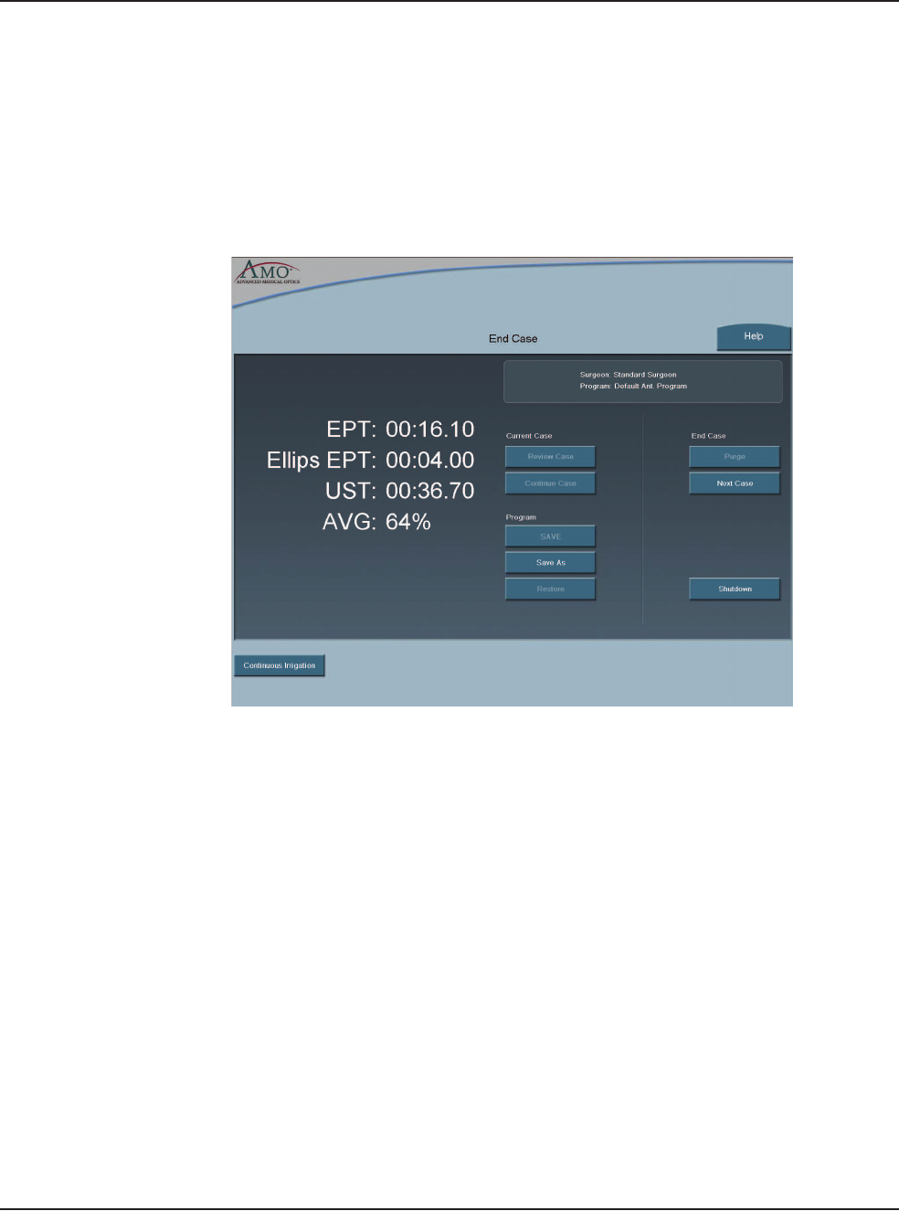
5 • Anterior Segment Surgery Operating Modes
WHITESTAR SIGNATURE™ System Rx Only – Z370147 Rev. C 1008 5-35
End Case
Purge – Select Purge to remove all of the fluid from the irrigation and aspiration
tubing before you remove the tubing cassette.
Next Case – Select Next Case to install a new tubing cassette.
Note: Use a new bottle of balanced salt solution at the start of each case.
Figure 5.27 – End Case Screen
The timers in the upper left corner indicate Effective Phaco Time (EPT), Ultrasonic
(U/S) Time in Footpedal Position 3, and Ellips EPT if Ellips™ Technology is On.
Effective Phaco Time is ultrasound time as a weighted total that takes into account
the amount of power being used:
• at 100% power: 1 sec. U/S Time = 1 sec. EPT
• at 50% power: 1 sec. U/S Time = .5 sec. EPT
Current Case
Review Case – shows the graphical history of the surgery. (Refer to Figure 5.28
Review Case Screen.)
1. Select a shorter time interval to adjust the Time Line Duration and to see
greater case details. For example, 10 Sec shows more detail than 15 Min.
2. Select a longer time interval for an overview of the surgery or sessions, such as
1 hour or 2 hours. This view provides less detail, but gives you a better
indication of the trends over a period of time. Use the << or >> buttons to
change the time intervals. You cannot use the arrow buttons when you view an
active case.
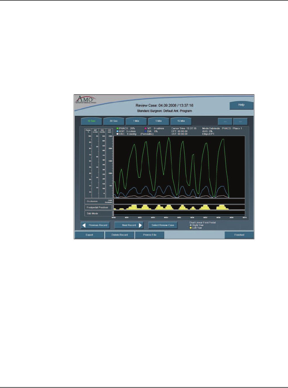
5 • Anterior Segment Surgery Operating Modes
WHITESTAR SIGNATURE™ System Rx Only – Z370147 Rev. C 1008 5-36
3. Press the Select Review Case to select and view a specific surgical case.
4. Press Export to name and save the record to a USB device. Enter a name for
the Case History.
Note: Use only AMO recommended USB stick drives.
5. Use the Print to File to save the data to a file format. The Delete Record
button removes the case from the Record database.
6. Select Finished to close the window.
Figure 5.28 – Review Case Screen
Continue Case – Select Continue Case to return to the current case, after you
selected Review Case or Restore.
Shutdown – Select the Shutdown button to turn the System Off. At the prompt,
press Yes to complete the process.
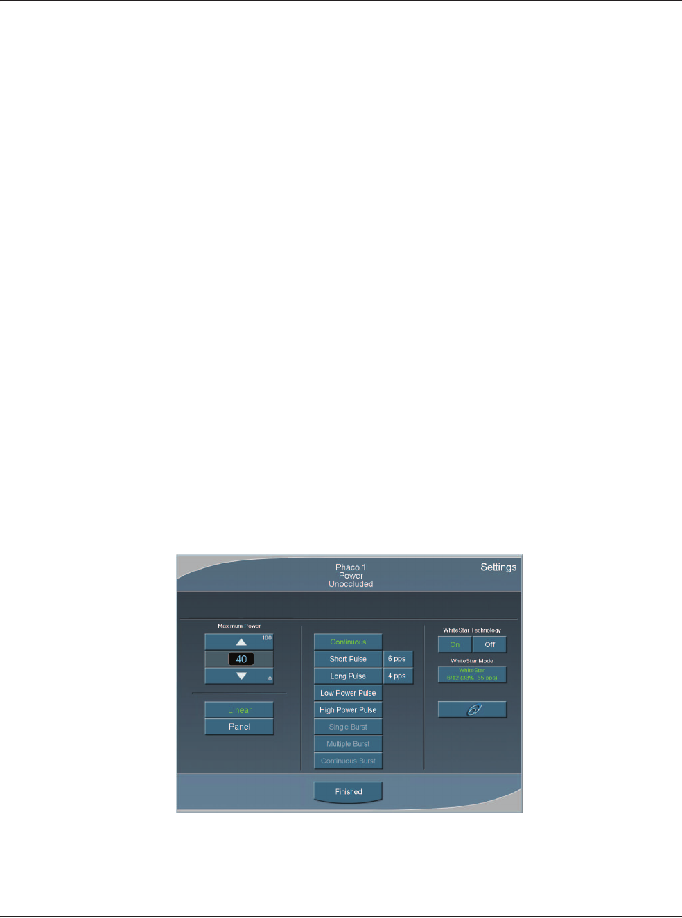
5 • Anterior Segment Surgery Operating Modes
WHITESTAR SIGNATURE™ System Rx Only – Z370147 Rev. C 1008 5-37
Anterior Segment –
Recommended
Settings
Phaco Power
You can adjust power from 0% to 100% in 5% increments for both Occluded and
Unoccluded phaco tips. The large number in the power panel indicates the selected
maximum Phaco Power. The phaco power can be either Linear or Panel.
1. Linear – Power is controlled with the footpedal, the power increases from 0%–
100% to the maximum preset level. When the footpedal is fully pressed, the
power level is at the maximum preset level. The power increase is indicated by
the power display bar.
2. Panel – Power is delivered consistently at the power level (%) indicated on the
screen. The power level does not change when you press the footpedal.
There are eight choices for delivery of phaco power:
•Continuous
•Short Pulse
•Long Pulse
•Low Power Pulse
•High Power Pulse
•Single Burst (Panel only)
•Multiple Burst (Panel only)
•Continuous Burst (Panel only)
From the PHACO operating screen, press Settings and the Phaco Power selection
screen appears.
Figure 5.29 – Phaco Power Settings
In addition to the eight Phaco Power modes, you can also select the WHITESTAR
Mode. The WHITESTAR® Technology and Ellips™ Technology are discussed
later in this section.
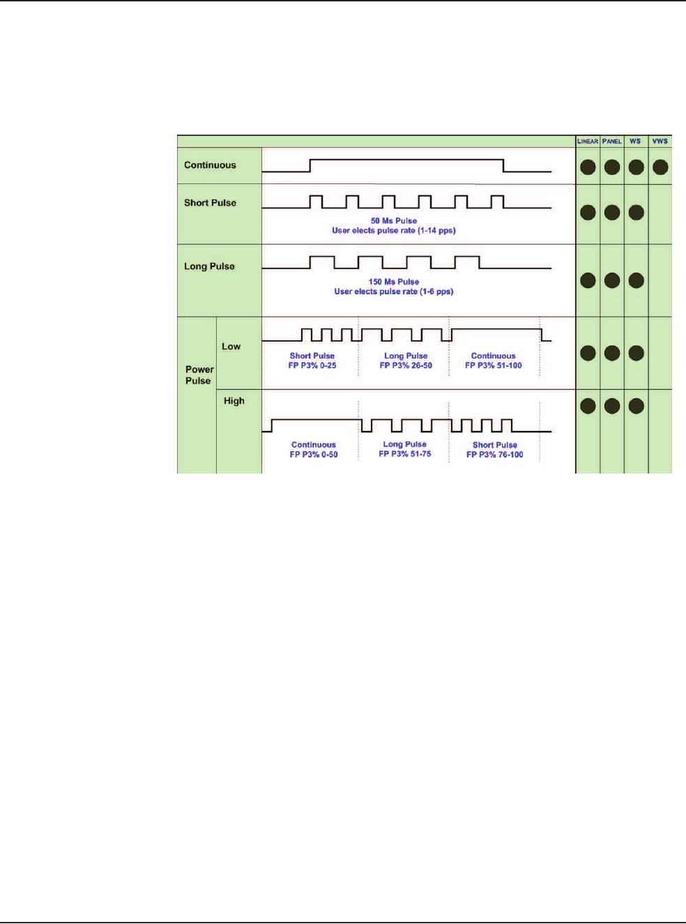
5 • Anterior Segment Surgery Operating Modes
WHITESTAR SIGNATURE™ System Rx Only – Z370147 Rev. C 1008 5-38
Continuous Phaco Power
Continuous Phaco Power delivers continuous, uninterrupted phaco power to the
handpiece and requires no pulse rate setting.
Figure 5.30 – AMO™ Phaco Power Modes
Short Pulse Phaco Power
Short Pulse delivers Phaco in pulses of 50 ms when the footpedal is in Position 3.
You can set this in a range of 1 to 14 pulses per second (pps). The actual number of
pps is shown on the button to the right of the Short Pulse button.
To set the Short Pulse range:
1. Press the button to the right of the Short Pulse button. A Settings pop-up
window appears.
2. Press the Up or Down arrow to increase or decrease the pps from 1 to 14.
3. Press Finished to close the window.
Long Pulse Phaco Power
Long Pulse delivers Phaco in pulses of 150 ms when the footpedal is in Position 3.
You can set this in a range of 1 to 6 pulses per second (pps). The actual number of
pps is displayed on the button to the right of the Long Pulse button.
To set the Long Pulse range:
1. Press the button to the right of the Long Pulse button. A Settings pop-up
window appears.
2. Press the Up or Down arrow to increase or decrease the pps from 1 to 6.