Jorjin Technologies WG7831DELF Wireless module User Manual 1
Jorjin Technologies Inc. Wireless module 1
Contents
- 1. User Manual
- 2. User manual
User Manual
a module solution provider
Operating User Manual
WG7831DELF
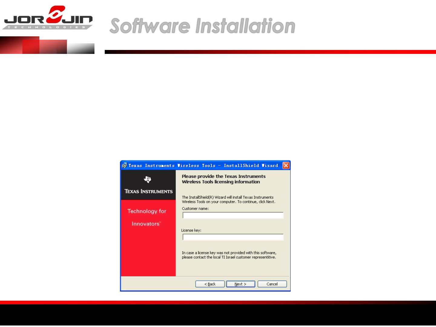
a module solution provider Software lnstallation
(1) Executive TI Wireless Tools HDK2.0.exe, met process of
following screen , please fill in
Customer name = Random
License Key = 644509802
Others Were to select the preset
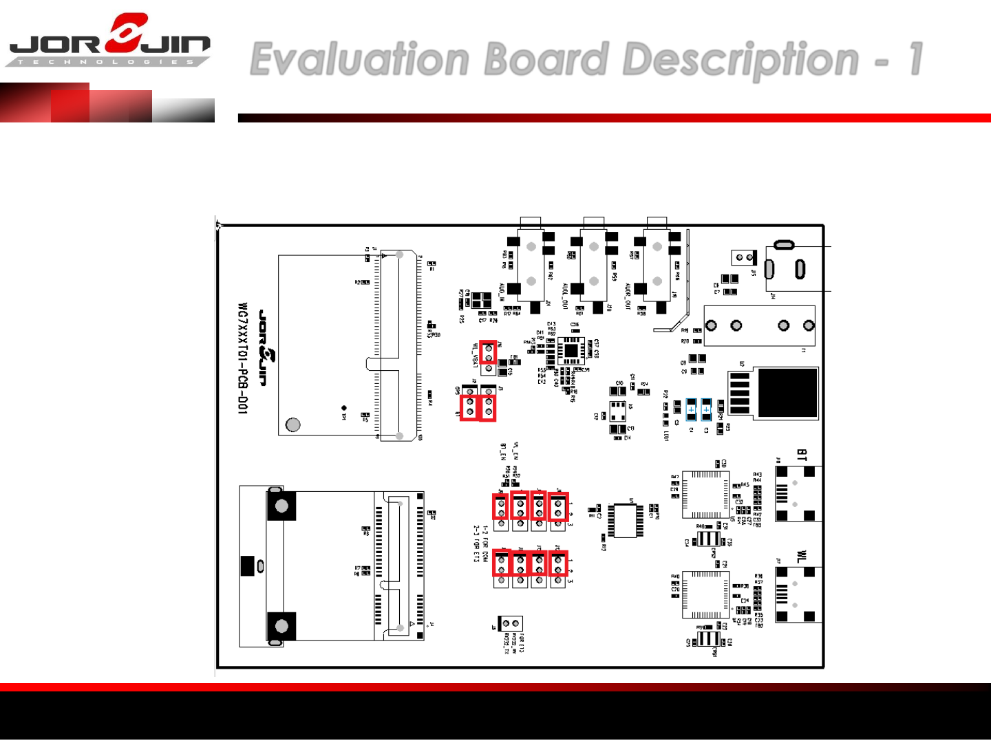
a module solution provider Evaluation Board Description - 1
Jumper insertion position for the red box
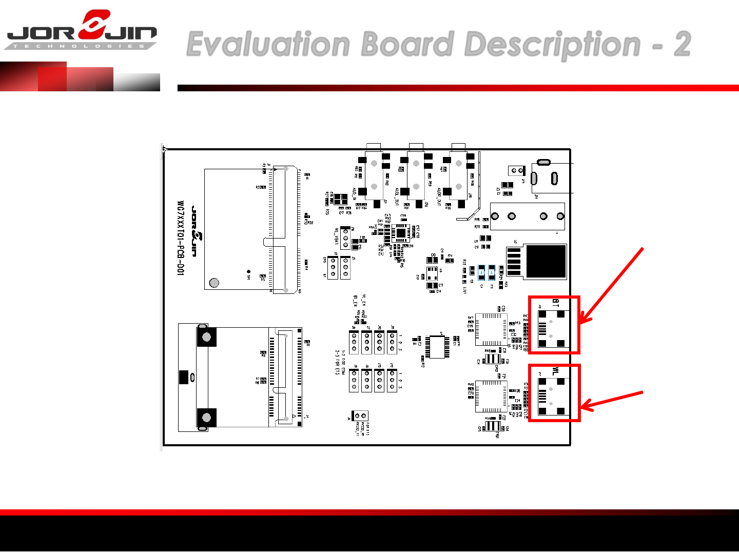
a module solution provider Evaluation Board Description - 2
BT Test
Connection USB
WIFI Test
Connection USB
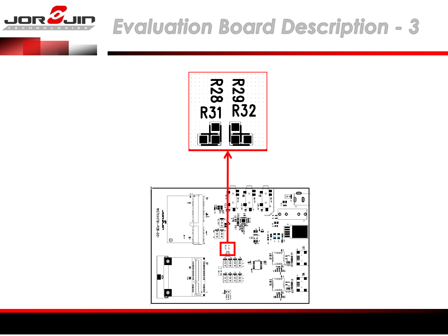
a module solution provider Evaluation Board Description - 3
BT ON : R28
BT OFF : R31
WIFI ON : R29
WIFI OFF : R32
a module solution provider
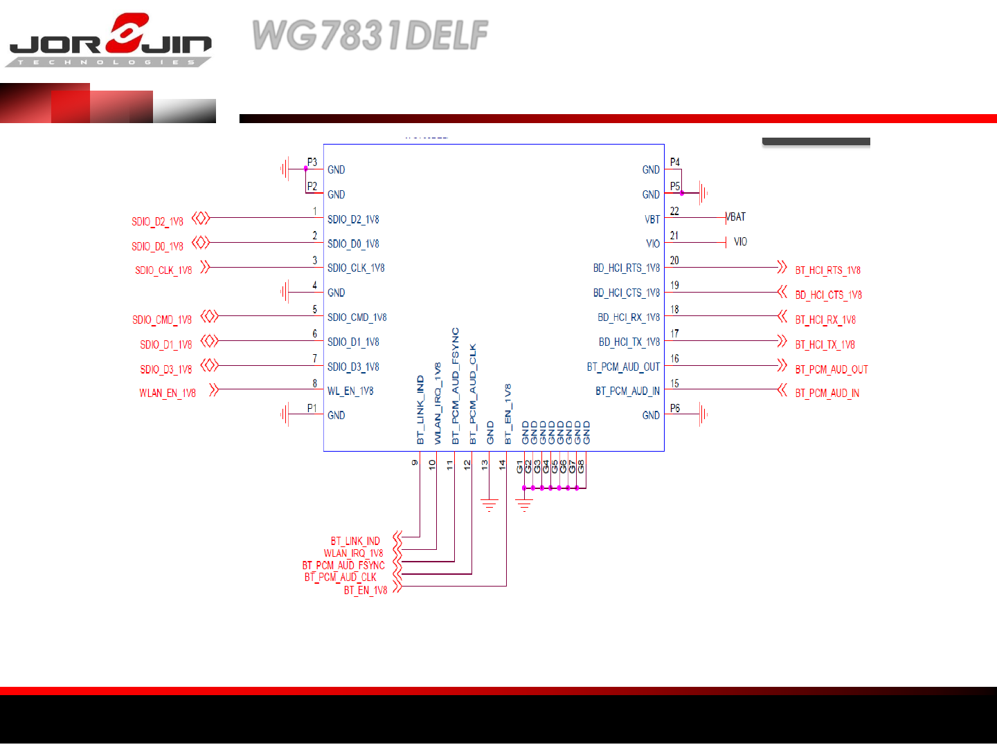
WG7831DELF
Reference Schematics
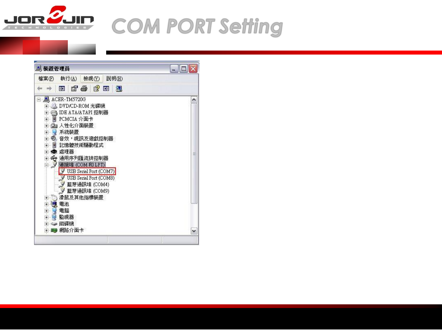
a module solution provider COM PORT Setting
1. Install TI Wireless Tools
2. When the hardware is connected to
the PC,
it is possible to find the port number for
communication.
Under the Device Manager, select Ports
(Com & LPT).
3. Run “RTTT” to start WiFi test software.
The USB ports are Com7 and Com8. Normally, the first
port, Com7, is the communication port, while the
next port, Com8, is the debug port.
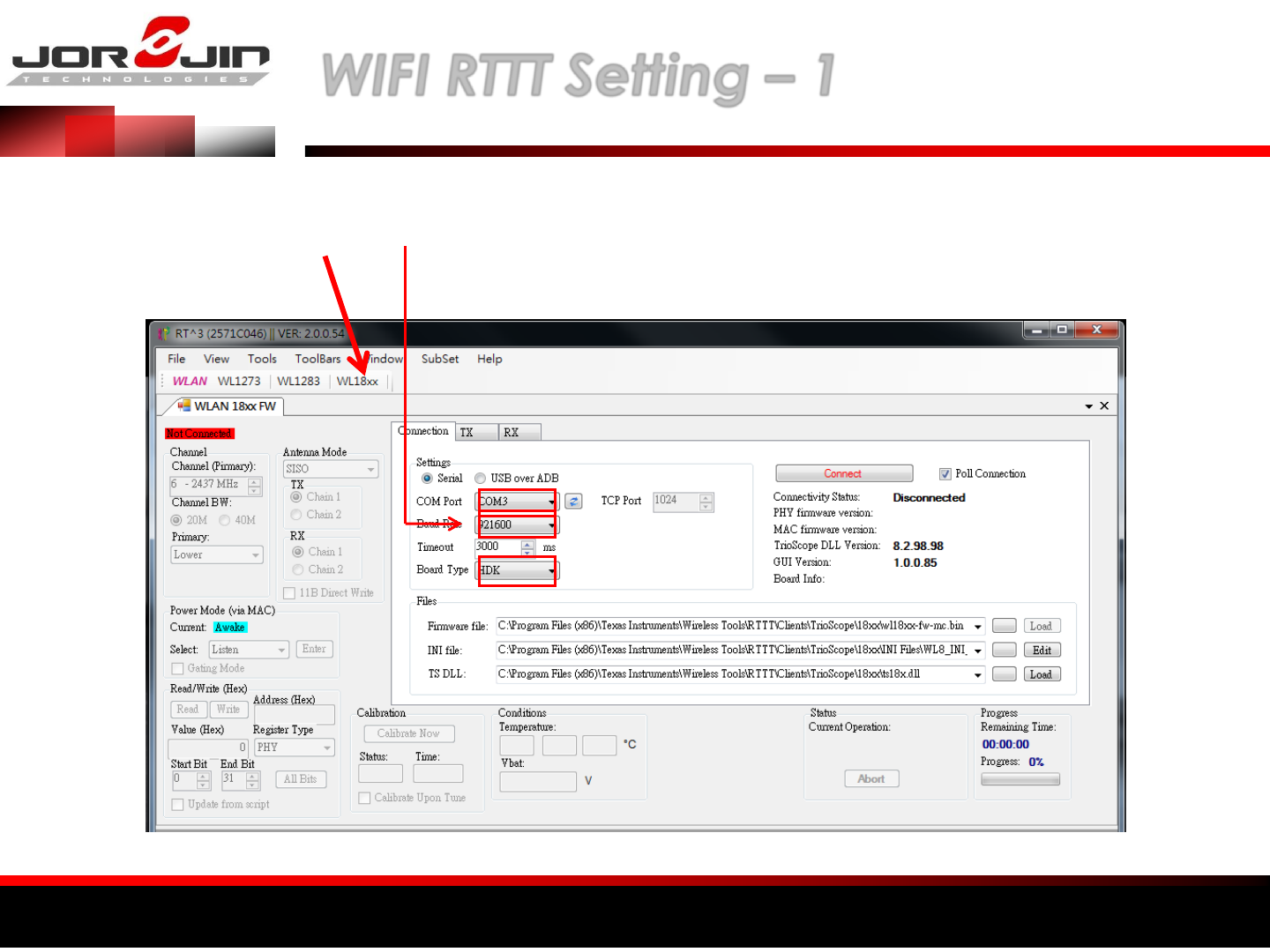
a module solution provider WIFI RTTT Setting – 1
(1) Select
WL18XX
(2) SET COM PORT
(3) SET Baud Rate ( 921600 )
(4) SET Board Type : HDK
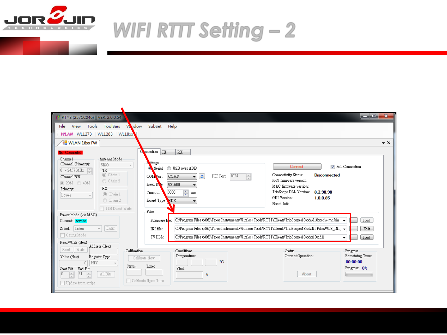
a module solution provider WIFI RTTT Setting – 2
Set file path
Firmware file : C:\Program Files (x86)\Texas Instruments\Wireless Tools\RTTT\Clients\TrioScope\18xx\wl18xx-fw-mc.bin
INI file : C:\Program Files (x86)\Texas Instruments\Wireless Tools\RTTT\Clients\TrioScope\18xx\INI Files\WL8_INI_2ANT.ini
TS DLL : C:\Program Files (x86)\Texas Instruments\Wireless Tools\RTTT\Clients\TrioScope\18xx\ts18x.dll
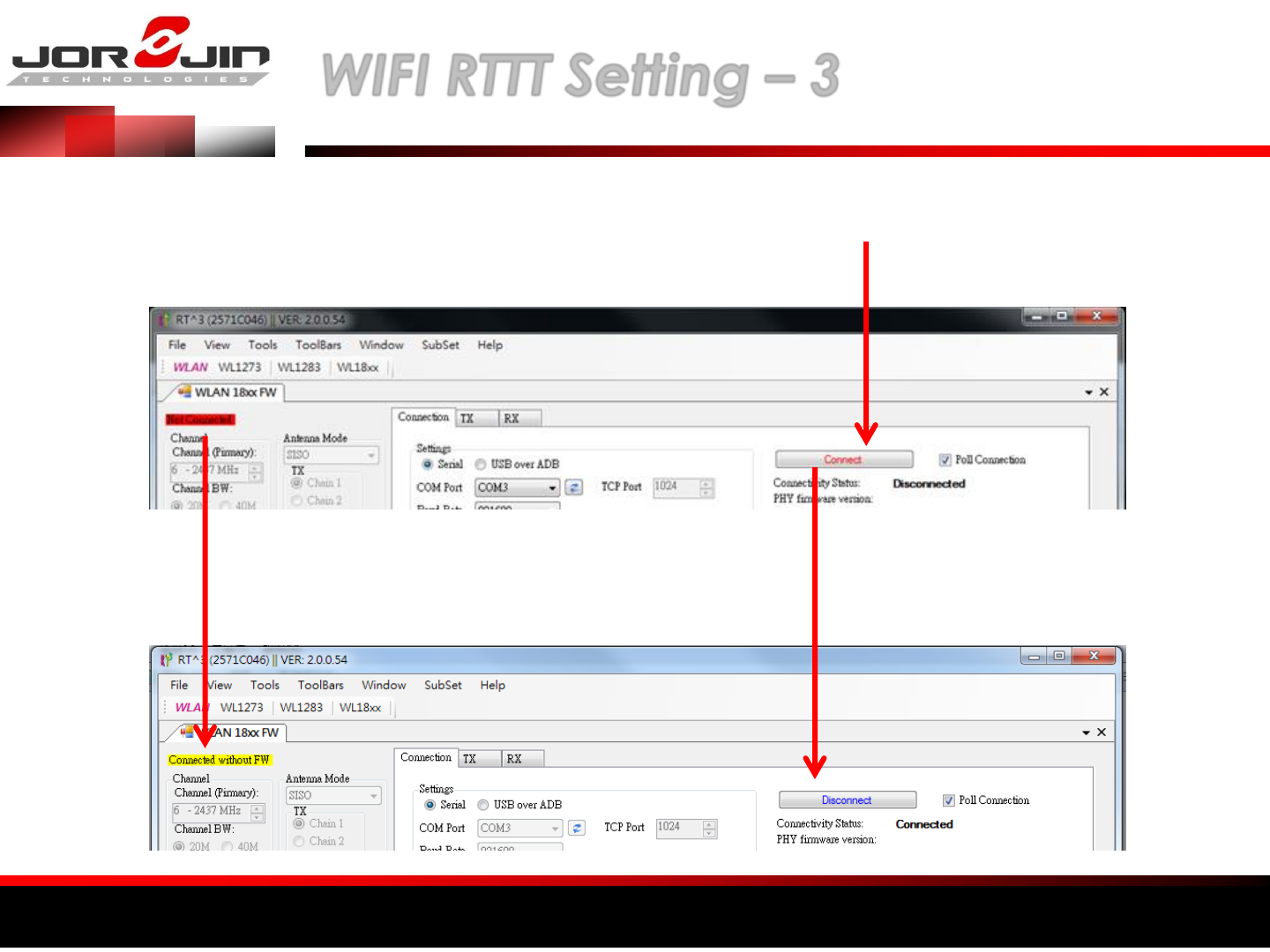
a module solution provider WIFI RTTT Setting – 3
Click Connect
Connected without FW
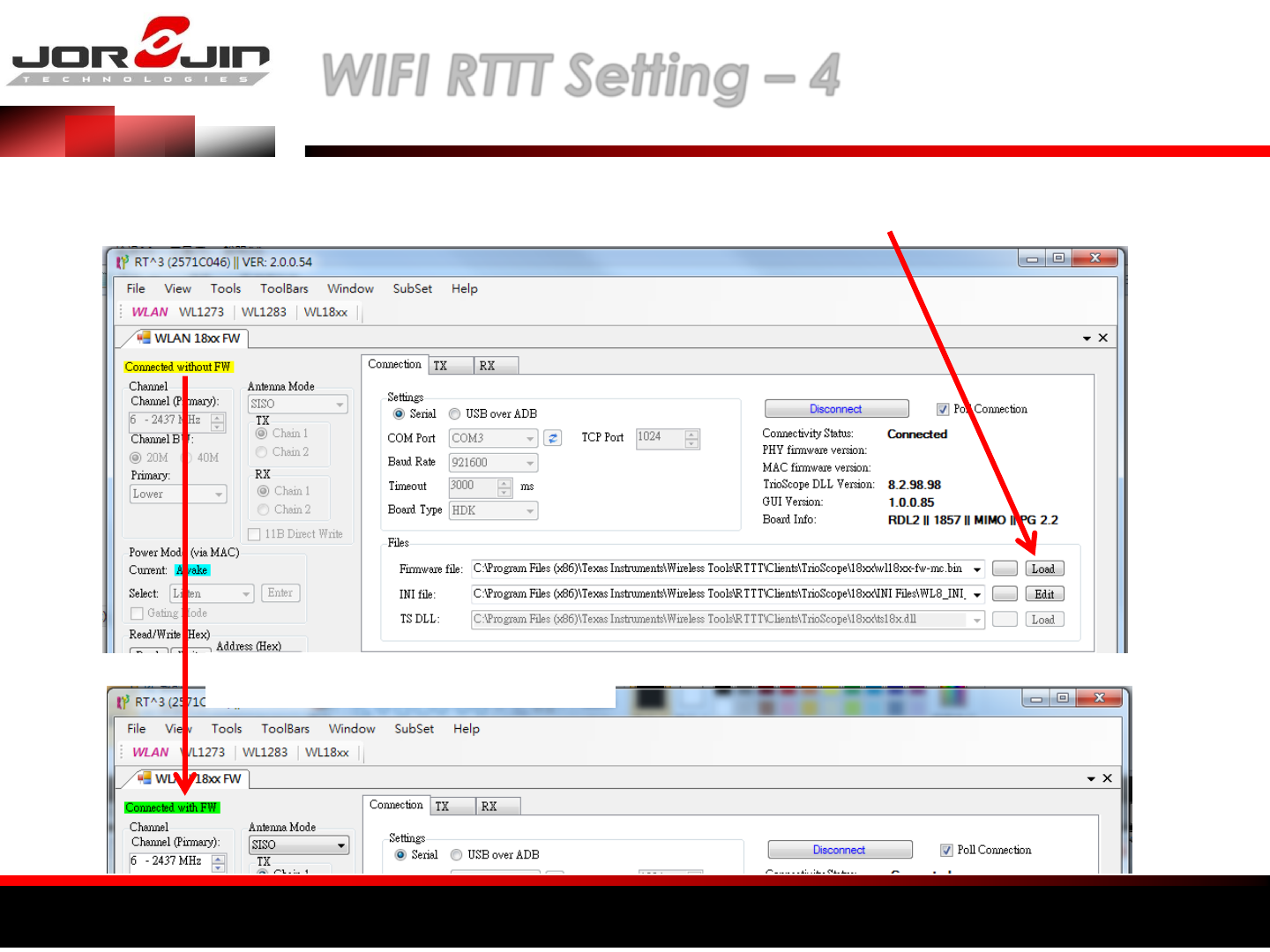
a module solution provider WIFI RTTT Setting – 4
Click “Load” to download Firmware
Download Success
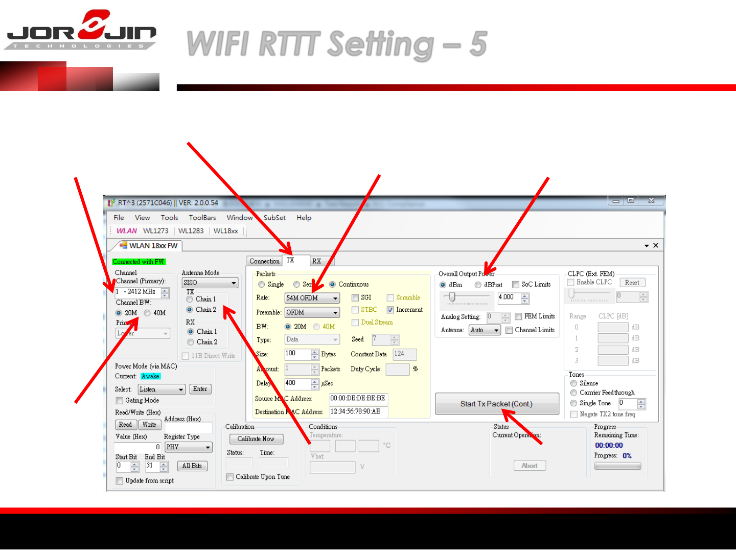
a module solution provider WIFI RTTT Setting – 5
Select TX or RX
Set channel
Select Channel
BW Set ANT
Select Modulation
and data rate Set Power
Switch TX ON/OFF
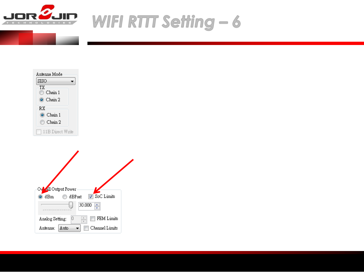
a module solution provider WIFI RTTT Setting – 6
NOTE: Chain 1 Express DUT ANT2,
Chain 2 EXpressDUT ANT1
Select dBm, Do not select dBPsat
Click SoC Limits, Power Limit Will be
locked the Dut settings. Power set
30dBm
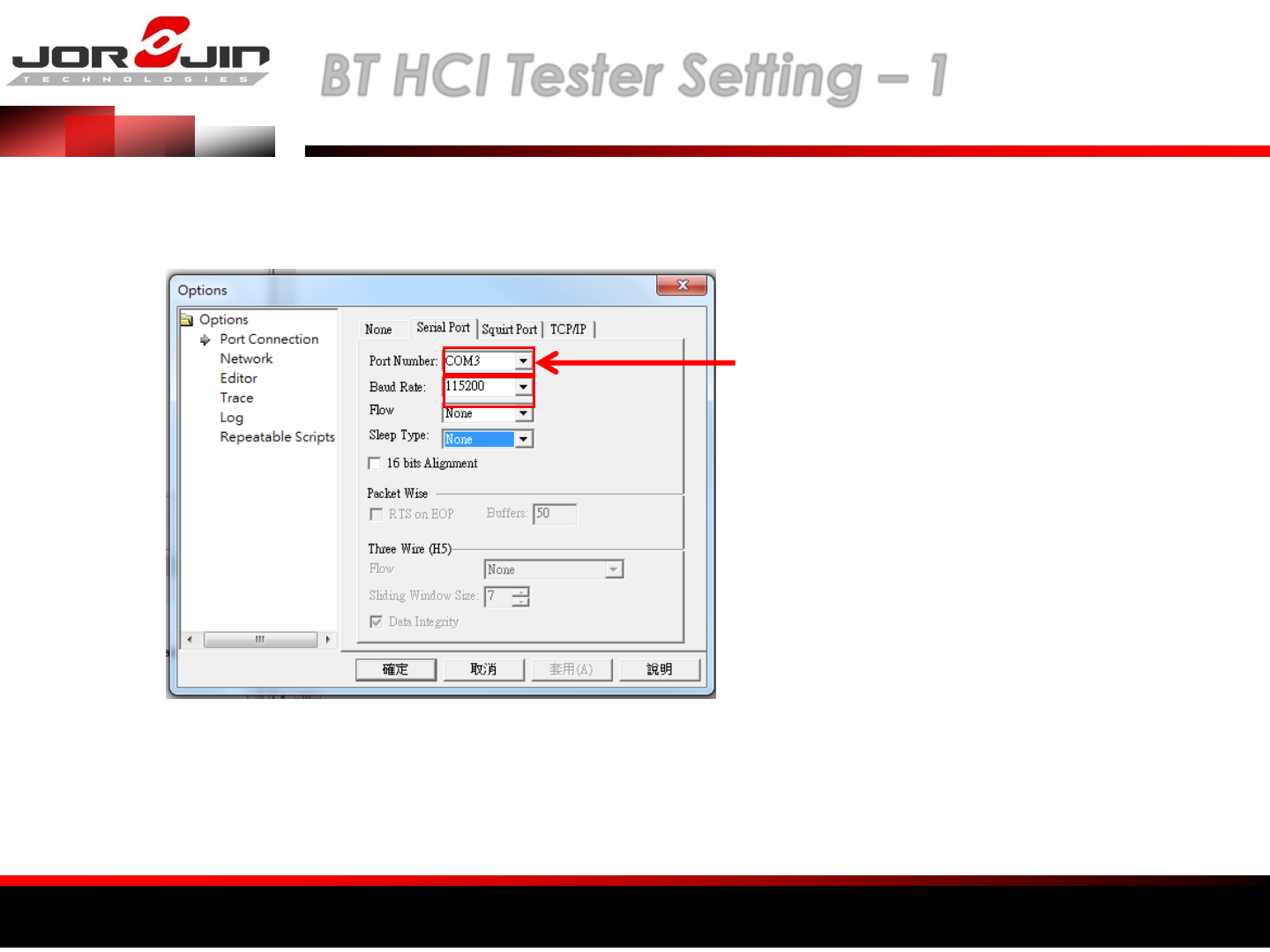
a module solution provider BT HCI Tester Setting – 1
(1) Execute HCI_Tester
(2) Select View Options
(3) SET COM PORT
and Baud Rate
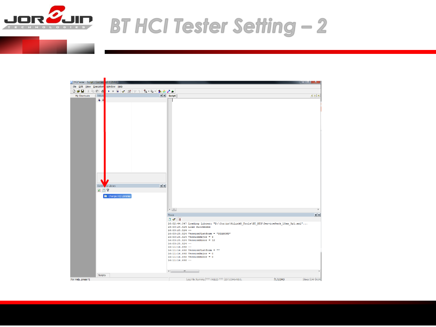
a module solution provider BT HCI Tester Setting – 2
(1) Add NEW XML file
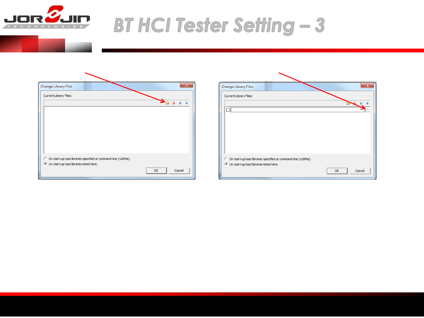
a module solution provider BT HCI Tester Setting – 3
(1) Select NEW (2) Select directory
(3) Select “ServicePack_18xx_3P1.xml”
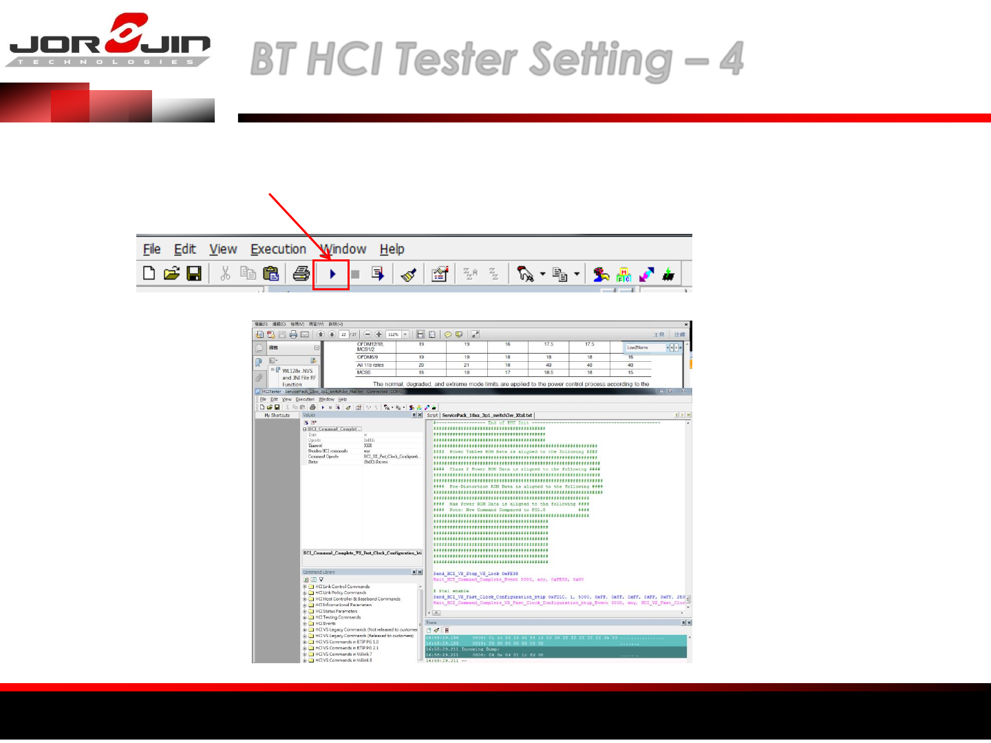
a module solution provider BT HCI Tester Setting – 4
(1) File Open, Select “ServicePack_18xx_3p1_switch3w_Xtal.txt”
(2) Select Execute Scripts
(3) All instructions execute in sequence automatically
a module solution provider 台灣NCC符合性聲明
經型式認證合格之低功率射頻電機,非經許可,公司、商號或使用者均不得擅
自變更頻率、加大功率或變更原設計之特性及功能。
低功率射頻電機之使用不得影響飛航安全及干擾合法通信;經發現有干擾現象
時,應立即停用,並改善至無干擾時方得繼續使用。前項合法通信,指依電信
法規定作業之無線電通信。低功率射頻電機須忍受合法通信或工業、科學及醫
療用電波輻射性電機設備之干擾。
Note: 系統廠商應於平台上標示「本產品內含射頻模組: XXXyyyLPDzzzz-x
(NCC ID) 」字樣

a module solution provider Regulatory information/warning
Manual Information to the End User
The OEM integrator has to be aware not to provide information to the end user regarding how to
install or remove this RF module in the user’s manual of the end product which integrates this
module. The end user manual shall include all required regulatory information/warning as show in
this manual.
Federal Communication Commission Interference Statement
This device complies with Part 15 of the FCC Rules. Operation is subject to the following two
conditions: (1) This device may not cause harmful interference, and (2) this device must accept
any interference received, including interference that may cause undesired operation.
This equipment has been tested and found to comply with the limits for a Class B digital device,
pursuant to Part 15 of the FCC Rules. These limits are designed to provide reasonable protection
against harmful interference in a residential installation. This equipment generates, uses and can
radiate radio frequency energy and, if not installed and used in accordance with the instructions,
may cause harmful interference to radio communications. However, there is no guarantee that
interference will not occur in a particular installation. If this equipment does cause harmful
interference to radio or television reception, which can be determined by turning the equipment
off and on, the user is encouraged to try to correct the interference by one of the following
measures:

a module solution provider Regulatory information/warning
- Reorient or relocate the receiving antenna.
- Increase the separation between the equipment and receiver.
- Connect the equipment into an outlet on a circuit different from that to which the receiver is
connected.
- Consult the dealer or an experienced radio/TV technician for help.
Any changes or modifications not expressly approved by the party responsible for
compliance could void the user's authority to operate this equipment.
This transmitter must not be co-located or operating in conjunction with any other antenna
or transmitter.
a module solution provider Regulatory information/warning
Industry Canada Statement
This device complies with Industry Canada license-exempt RSS standard(s). Operation is
subject to the following two conditions:
(1) this device may not cause interference, and
(2) this device must accept any interference, including interference that may cause
undesired operation of the device.
Le présent appareil est conforme aux CNR d'Industrie Canada applicables aux appareils
radio exempts de licence. L'exploitation est autorisée aux deux conditions suivantes:
(1) l'appareil ne doit pas produire de brouillage, et
(2) l'utilisateur de l'appareil doit accepter tout brouillage radioélectrique subi, même si le
brouillage est susceptible d'en compromettre le fonctionnement."
CAN ICES-3(B)/ NMB-3(B)
Radiation Exposure Statement
This equipment complies with FCC/IC radiation exposure limits set forth for an uncontrolled
environment. This equipment should be installed and operated with minimum distance
20 cm between the radiator & your body.

a module solution provider Regulatory information/warning
End Product Labeling
When the module is installed in the host device, the FCC/IC ID label must be visible through
a window on the final device or it must be visible when an access panel, door or cover is
easily re-moved. If not, a second label must be placed on the outside of the final device that
contains the following text: “Contains FCC ID: WS2-WG7831DELF” “Contains IC: 10462A-
WG7831DELF “
The grantee's FCC ID/IC ID can be used only when all FCC/IC compliance requirements are
met.
This device is intended only for OEM integrators under the following conditions:
(1) The antenna must be installed such that 20 cm is maintained between the antenna and
users,
(2) The transmitter module may not be co-located with any other transmitter or antenna.
(3) The Chip antenna with -2.46 dBi gain was verified in the conformity testing. Radiated
transmit power must be equal to or lower than that specified in the FCC/IC Grant of
Equipment Authorization for FCC ID: WS2-WG7831DELF and IC: 10462A-WG7831DELF. A
separate approval is required for all other antenna type, or higher gain antenna.

a module solution provider Regulatory information/warning
In the event that these conditions cannot be met (for example certain laptop configurations
or co-location with another transmitter), then the FCC/IC authorization is no longer
considered valid and the FCC ID/IC ID cannot be used on the final product. In these
circumstances, the OEM integrator will be responsible for re-evaluating the end product
(including the transmitter) and obtaining a separate FCC/IC authorization.