Jotron AS L3FFSVR Protective Capsule for S-VDR and EPIRB User Manual tron ny manual
Jotron AS Protective Capsule for S-VDR and EPIRB tron ny manual
UserManual.wiki
>
Jotron AS
>
L3FFSVR User Manual
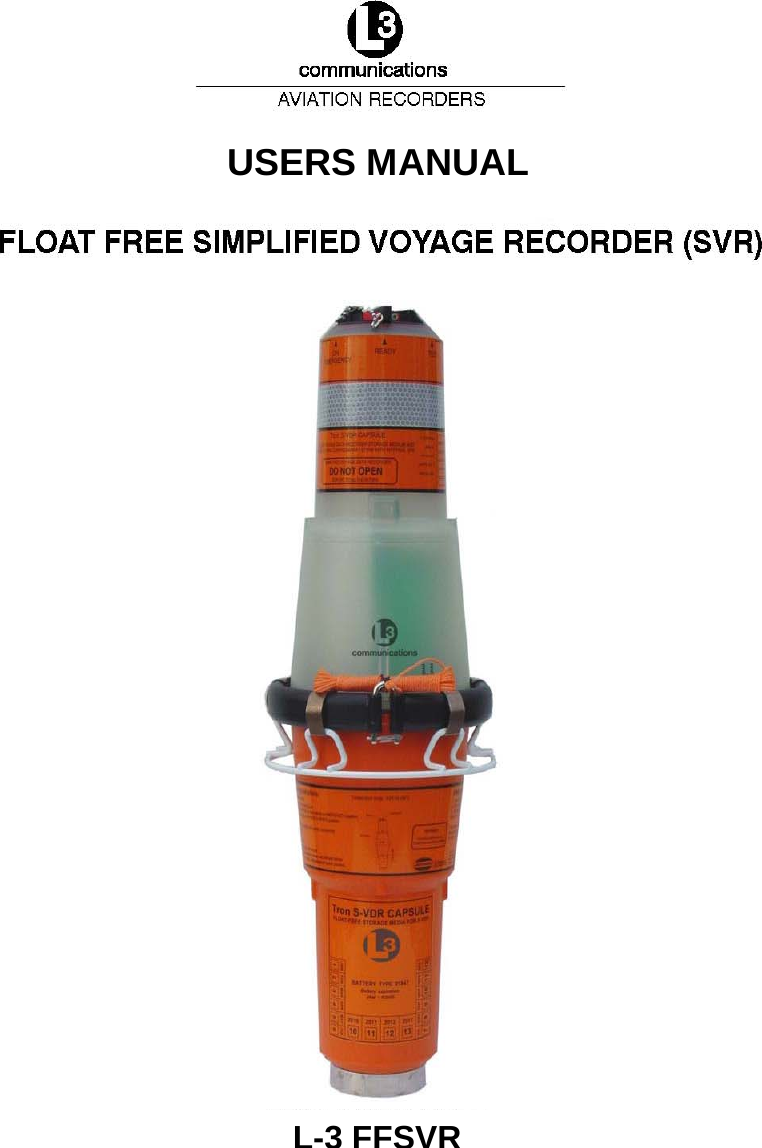
Users Manual
Navigation menu
Upload a User Manual
Namespaces
Wiki Guide
HTML
PDF
Info
Views
User Manual
Discussion / Help
Navigation
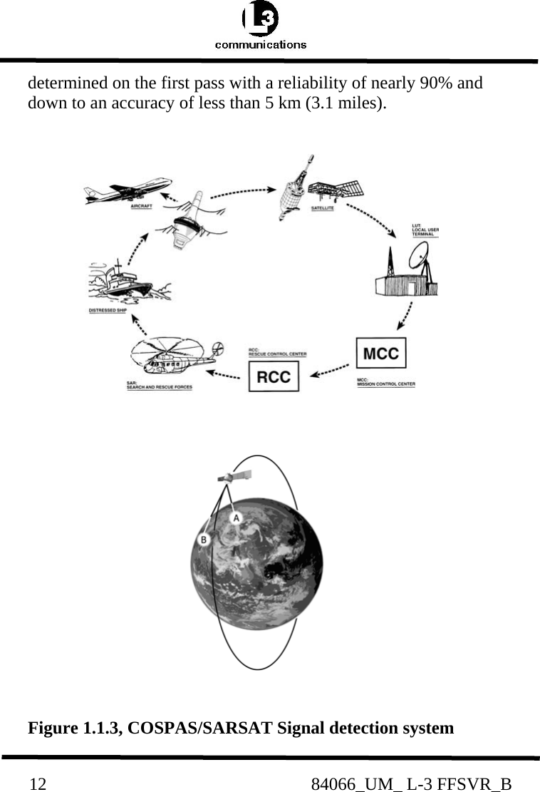
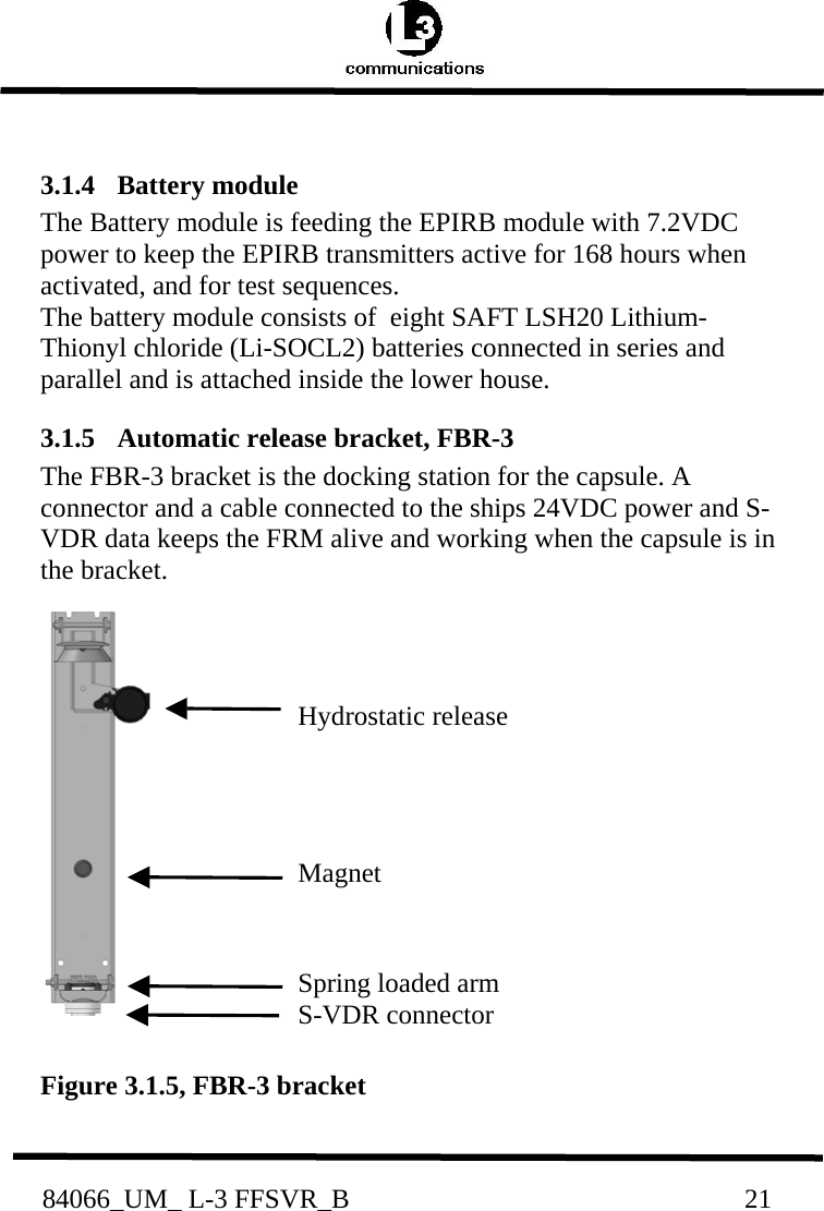
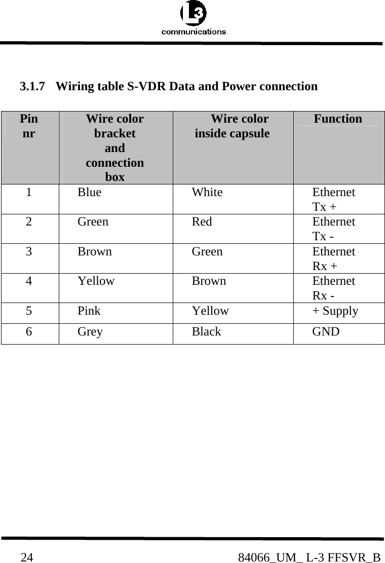
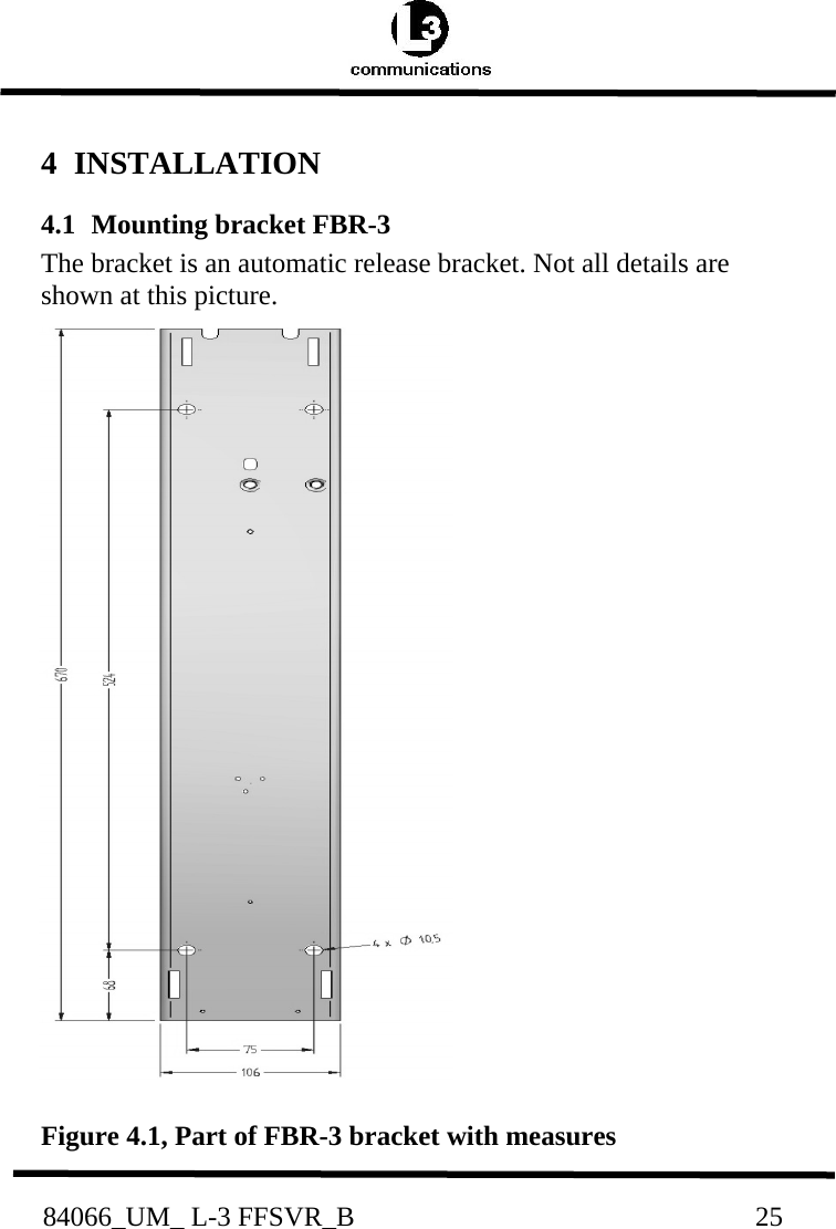
![84066_UM_ L-3 FFSVR_B 11 ground station. The ground station or LUT has a 2500 km satellite reception radius centered at the LUT. In areas without LUT coverage (mostly less populated areas in the southern hemisphere), signals from the 121.5MHz transmitter will not be detected by the satellites, only by passing aircraft’s. From the year 2006,no new satellites will be launched including 121.5MHz receiver, and from the year 2009,satellitedetection of the 121.5MHz EPIRB is terminated. This is not the case with the 406MHz transmitter, because the satellites have a memory unit, which stores the signals for relay to the next available LUT giving it a truly global coverage. Once the signal is received by the LUT, it is processed for location and sent to a Mission Control Center (MCC).The MCC sorts the alert data according to geographic search and rescue regions and distributes the information to the appropriate Rescue Co-ordination Center (RCC), or if outside the national search and rescue area, to the appropriate MCC that covers the area that the distress signal was detected. The RCC in turn takes the necessary action to initiate search and rescue activities. 1.1.3 Distress location determination The location of the distress signal is determined by taking measurements of the doppler shift of the EPIRB frequency when the satellite first approach and then pass the EPIRB. The actual frequency is heard at the time of closest approach (TCA). Knowing the position of the satellite and using the received doppler signal information, it is possible to determine the location of the Capsule from the satellite at the TCA. At the LUT, actually two positions are calculated. One is the actual position (A) and the other is the mirror image (B) position [FIG.1.1.3]. A second satellite pass confirms the correct location (A).With the 406MHzsystem the real solution can be](https://usermanual.wiki/Jotron-AS/L3FFSVR/User-Guide-862600-Page-11.png)