Jotron AS RA-7203C VHF Receiver 156.300-162.000MHz for coast stations and offshore installations requiring high quality FM voice and digital selective calling (DSC) User Manual Operators handbook TR7750
Jotron AS VHF Receiver 156.300-162.000MHz for coast stations and offshore installations requiring high quality FM voice and digital selective calling (DSC) Operators handbook TR7750
Users Manual
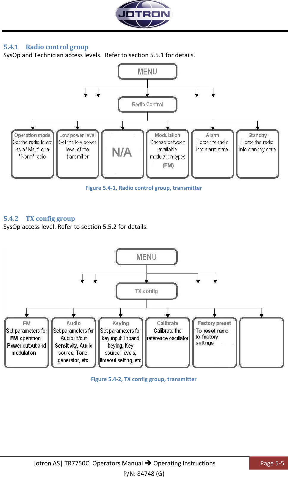
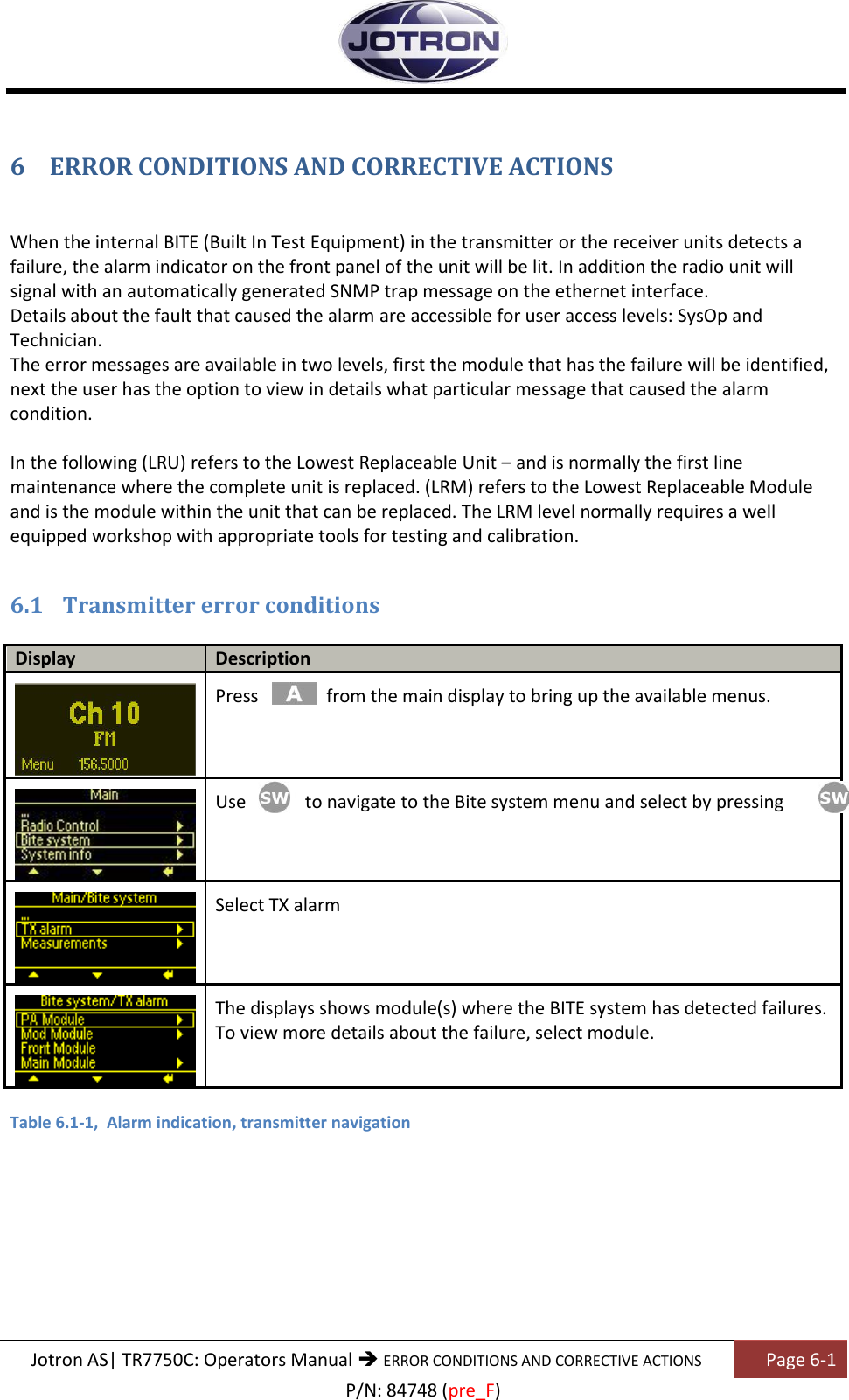
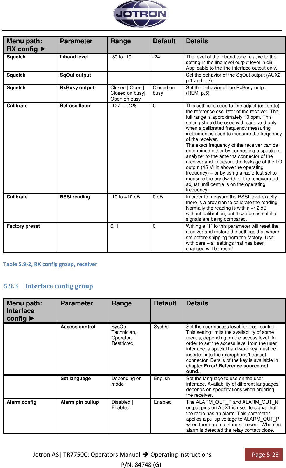
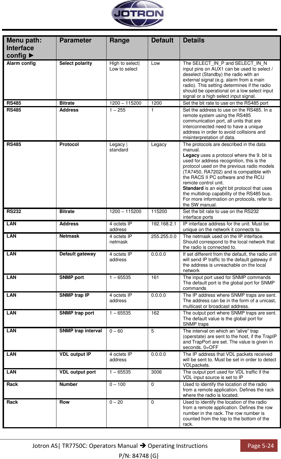
![Jotron AS| TR7750C: Operators Manual Operating Instructions Page 5-14 P/N: 84748 (G) 5.5.4 Bite system group Menu path: Interface config ► Parameter Range Default Details TX alarm Depends on the alarm status of the radio unit This option displays all active alarms in the unit. See section 6.1 for more info. Measurements Forward 30 – 47 dBm Displays the forward power in dBm detected at the output of the transmitter Measurements Reflected 0 – Forward power Displays the reflected power in dBm detected on the output of the transmitter Measurements VSWR 1 : ∞ Displays the calculated VSWR from the forward and reflected measurements Measurements Modulation Up to ± 5kHz Displays the measured modulation level on the output of the transmitter [kHz] Measurements Current Max 10 A when keyed Displays the total current consumption (28V) of the transmitter [A] Measurements PA Temp Max 85°C Displays the temperature measured on the PA module in the transmitter [°C] Measurements LO level Min. 0 dBm Displays the level measured at the output of the local oscillator in dBm Measurements Line level Input line level Displays the input line level in dBm Measurements 28 Volt 20.0 – 29.0 V Displays the regulated 28V supply from the power regulator board. The 28V is used on the PA board. Measurements 12 Volt 11.0 – 12.8 V Displays the regulated 12V supply from the power regulator board The 12V is used on the main board Measurements 6 Volt 5.0 – 7.0 V Displays the regulated 6V on the modulator board Measurements 5 Volt 4.5 – 5.5 V Displays the regulated 5V supply from the power regulator board. The 5V is used on several modules Measurements -5 Volt -6.2 - -4.0 V Displays the regulated -5V supply from the power regulator board. The -5V is used on the main board. Measurements 3.3 Volt 2.9 – 3.6 V Displays the regulated 3.3V supply from the power regulator board. The 3.3V is used on several modules Table 5.5-4, Bite system group, transmitter](https://usermanual.wiki/Jotron-AS/RA-7203C/User-Guide-2287888-Page-64.png)

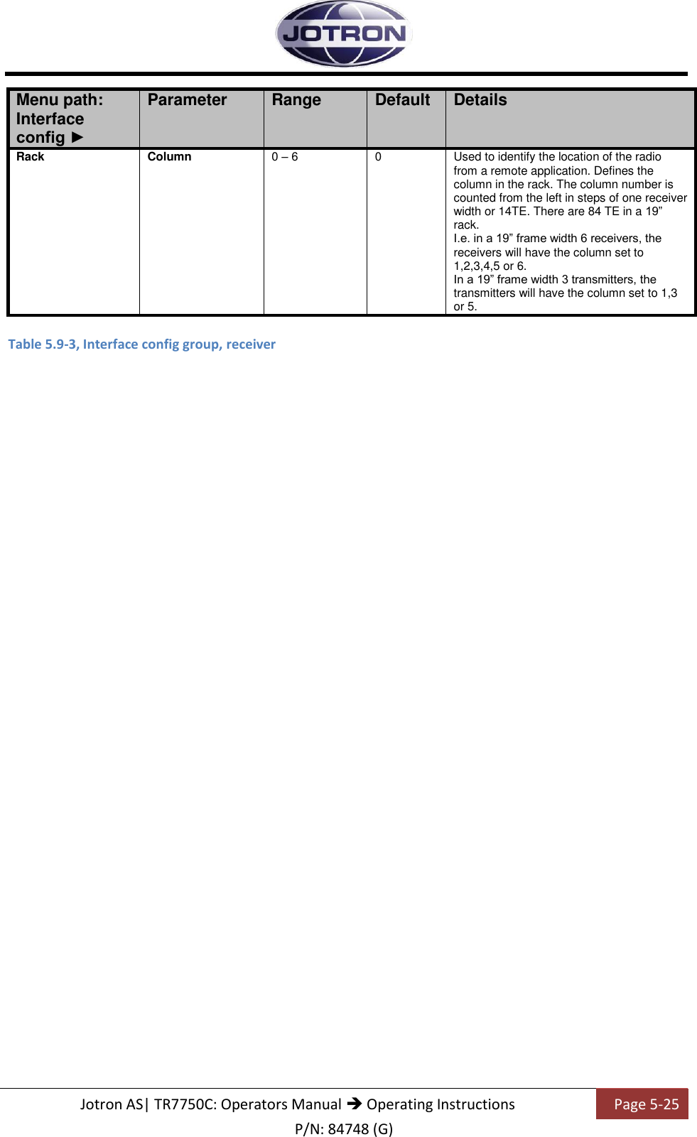
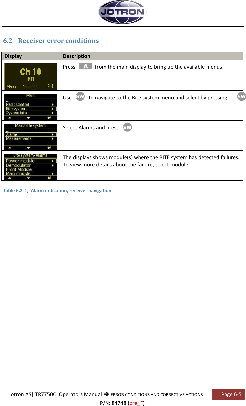
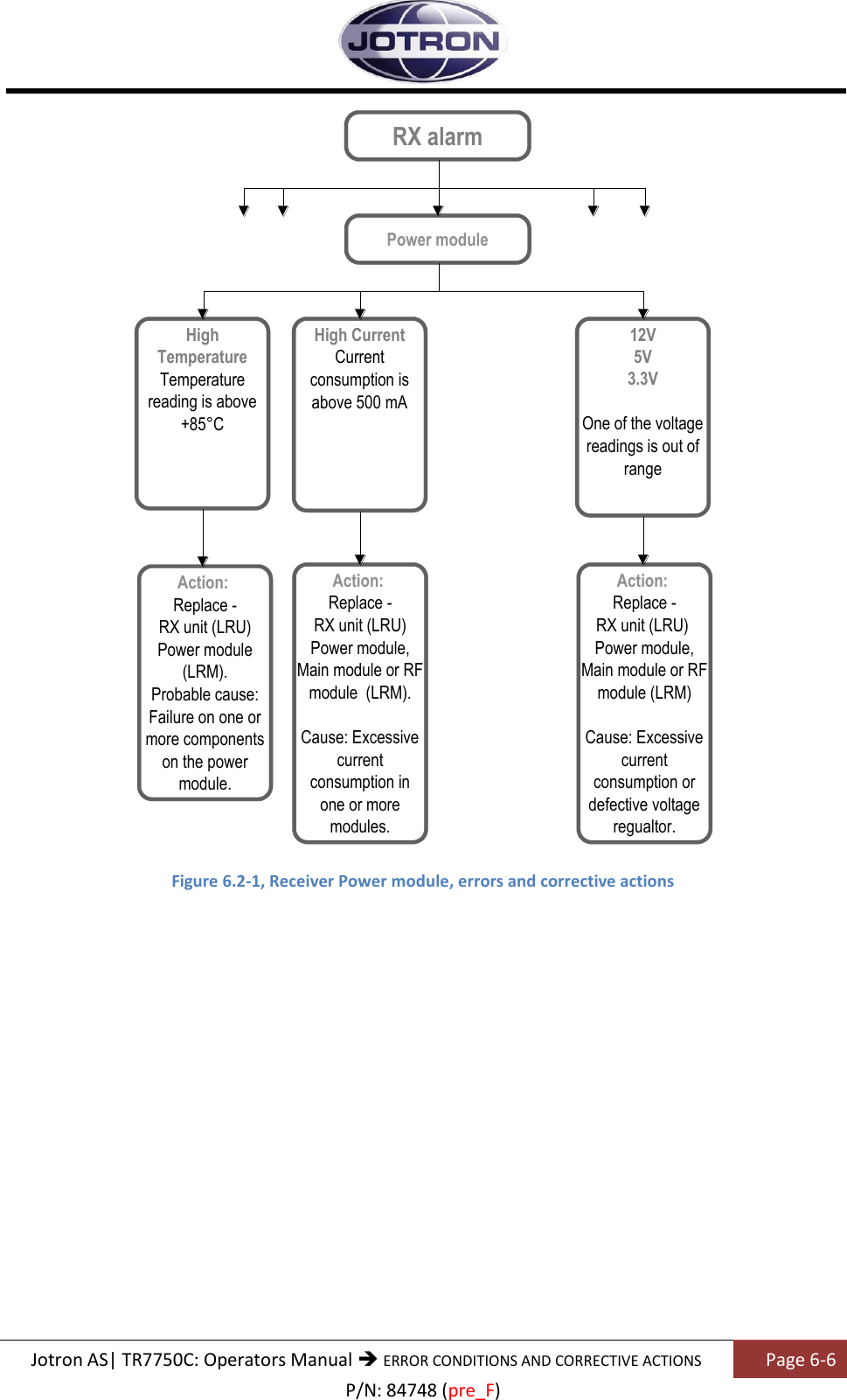
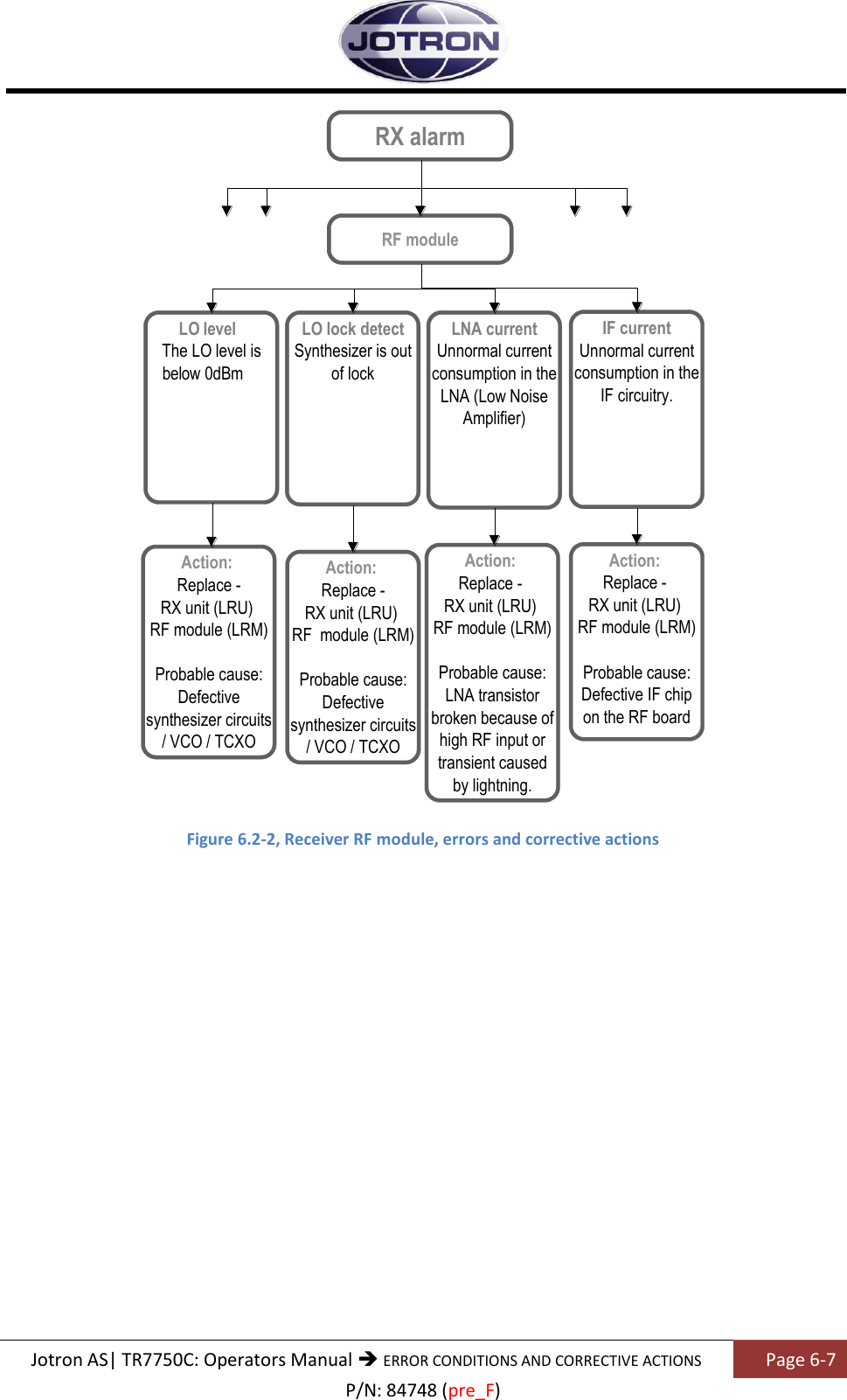
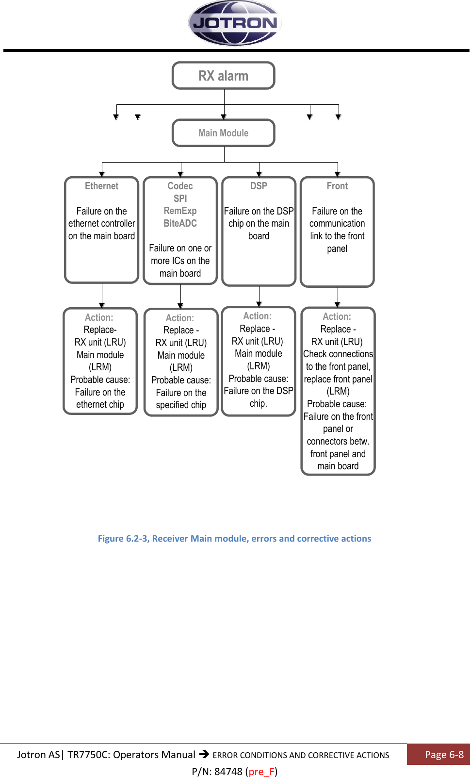
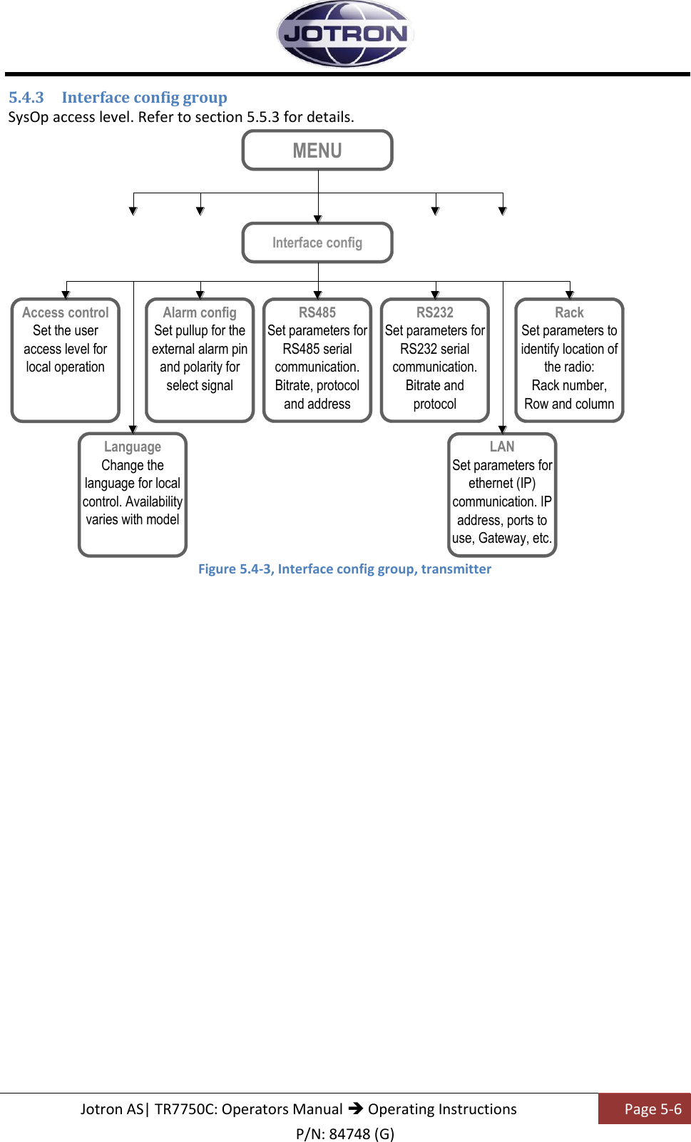
![Jotron AS| TR7750C: Operators Manual Operating Instructions Page 5-26 P/N: 84748 (G) 5.9.4 Bite system group Menu path: Interface config ► Parameter Range Default Details RX alarm Depends on the alarm status of the radio unit This menu item displays all active alarms in the unit. See Receiver error conditions for more information Measurements RSSI -10 - +110 dBuV Displays the received signal level (RSSI) in dbuV Measurements Line level -40 - +10 dBm Displays the level measured on the output of the 600 ohm line interface Measurements AGC volt 0 – 5 V Displays the internal AGC voltage Measurements Codec/Eth LD Lock / Unlock Displays the status of the VCO used for the Codec and Ethernet chips. Measurements Temperature Max 85°C Displays the internal temperature measured on the main board [°C] Measurements DC current 0.1 – 0.3 A Displays the total current consumption [28V] of the receiver [A] Measurements IF current 20 – 60 mA Displays the current consumption in the IF (Intermediate Frequency) circuit [mA] Measurements LNA current 20 – 60 mA Displays the current consumption in the LNA (Low noise amplifier) [mA] Measurements LO level Min. 15 dBm Displays the level measured at the output of the local oscillator in dBm Measurements LO lock Lock / Unlock Displays the status of the local oscillator in the receiver. Measurements 12 Volt 11.0 – 12.8V Displays the regulated 12V supply from the power supply board The 12V is used on the main board Measurements 6 Volt 5.0 – 7.0V Displays the regulated 6V on the demodulator board Measurements 5 Volt 4.5 – 5.5V Displays the regulated 5V supply from the power supply board. The 5V is used on several modules Measurements 3.3 Volt 2.9 – 3.6V Displays the regulated 3.3V supply from the power supply board. The 3.3V is used on several modules Measurements AC Present/Not Present / Not present. Signals that AC is present or not present at the input of the unit. Measurements VDL2-CO 0 – 100 % Displays the channel occupancy (CO) when in VDL 2 mode. The value is calculated every second, or by the interval set in VDL2-CO Trap interval. Table 5.9-4, Bite system group, receiver](https://usermanual.wiki/Jotron-AS/RA-7203C/User-Guide-2287888-Page-76.png)