Jotron AS RA-7203C VHF Receiver 156.300-162.000MHz for coast stations and offshore installations requiring high quality FM voice and digital selective calling (DSC) User Manual Operators handbook TR7750
Jotron AS VHF Receiver 156.300-162.000MHz for coast stations and offshore installations requiring high quality FM voice and digital selective calling (DSC) Operators handbook TR7750
Users Manual


Jotron AS| TR7750C: Operators Manual Introduction
Page ii
P/N: 84748 (G)
Approvals
The equipment is designed to meet the essential requirements of European Directives 1999/5/EC,
89/336EEC as amended by Directive 93/68/EEC and 72/23/EEC
Standards
The following standards are applied:
EMC: EN301843-1 and EN301843-2
FCC part 80
Health and Safety: EN60950
Radio specifications: EN301929-1 and EN301929-2
For an updated list of approvals and statements of conformity, these are available on:
www.jotron.com

Jotron AS| TR7750C: Operators Manual Introduction
Page iii
P/N: 84748 (G)
List of abbreviations and definitions
BITE
Built In Test Equipment
bps
Bits Per Second.
DSP
Digital Signal Processor
ETSI
European Telecommunication Standardisation Institute
ICAO
International Civil Aviation Organization
IEC
International Electro-technical Commission.
LAN
Local Area Network
PA
Power Amplifier
PSU
Power Supply Unit. Separate unit to power the equipment.
PTT
Push To Talk
RF
Radio Frequency
S/N
SIGNAL- TO-NOISE RATIO
SNMP
Simple Network Management Protocol, a network protocol used to control the radio equipment.
This equipment is defined as an AGENT in a SNMP system.
VSWR
Voltage Standing Wave Ratio

Jotron AS| TR7750C: Operators Manual Introduction
Page iv
P/N: 84748 (G)
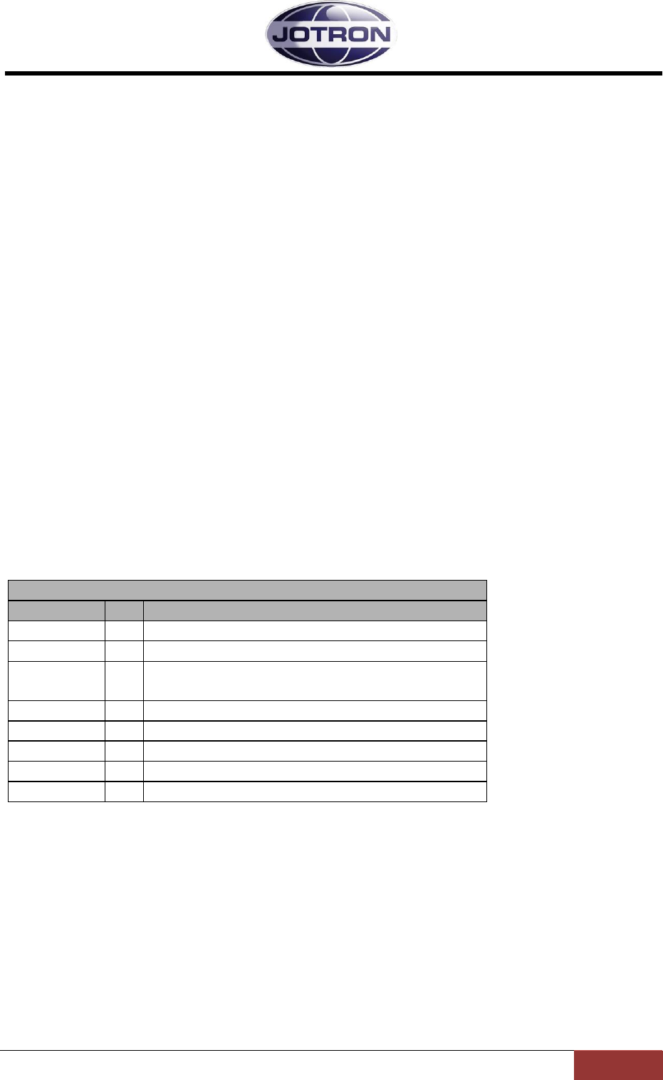
Amendment Record
NO
INIT
DATE
CHAPTERS
VERSION
REASONFOR CHANGE
1
ES
13.08.08
All
84748_O
perators
_TR7000
C_A
New product
2
OH
11.11.08
3.2.5, 3.2.6, 3.2.7,
3.4.4, 3.4.5, 3.4.6
B
Information regarding Frequency stability,
Hardware Key and protection of I/O lines added.
3
ES
29.06.09
3-5
C
Information regarding type of LAN cable
4
OH
10.11.09
3.4.5, 1.1
D
Pin 8 Aux 2 is N/C, Output power configuration
range in radio model table.
5
BA
05.04.13
3.2.7, 3.2.8, 3.4.6,
4.6.1
E
Fixed RS485 polarity error.
6
BR
28.04.14
4.4
F
FCC and IC approval
7
BA
04.06.14
Page vi
G
Added warning statement, modification warning
statement and digital device statement.
8
9
10
11
12
13
14
15
16
17
18
19
20
The information in this book has been carefully checked and is believed to be accurate. However, no
responsibility is assumed for inaccuracies.
Jotron AS reserves the right to make changes without further notice to any products or modules
described herein to improve reliability, function or design. Jotron AS does not assume any liability
arising out of the application or use of the described product.

Jotron AS| TR7750C: Operators Manual Introduction
Page v
P/N: 84748 (G)
SAFETY INSTRUCTIONS
CAUTION!
This equipment contains CMOS integrated circuits. Observe handling precautions to avoid static
discharges which may damage these devices.
WARNING!
Some RF semiconductor devices used in this equipment may contain Beryllium Oxide. If inhaled, dust
from this oxide can be toxic. No danger will arise from normal handling but no attempt should be
made to tamper with these devices. On no account must these transistors be destroyed or discarded
with industrial or domestic waste, but should be returned to the manufacturers for subsequent
disposal.

Jotron AS| TR7750C: Operators Manual Introduction
Page vi
P/N: 84748 (G)
WARNING STATEMENT
This device complies with part 15 of the FCC Rules. Operation is subject to the following two
conditions: (1) This device may not cause harmful interference, and (2) this device must accept any
interference received, including interference that may cause undesired operation.
MODIFICATION WARNING STATEMENT
Changes or modifications not expressly approved by the party responsible for compliance could void
the user's authority to operate the equipment.
DIGITAL DEVICE STATEMENT
This equipment has been tested and found to comply with the limits for a Class B digital device,
pursuant to part 15 of the FCC Rules. These limits are designed to provide reasonable protection
against harmful interference in a residential installation. This equipment generates, uses and can
radiate radio frequency energy and, if not installed and used in accordance with the instructions, may
cause harmful interference to radio communications. However, there is no guarantee that
interference will not occur in a particular installation.
If this equipment does cause harmful interference to radio or television reception, which can be
determined by turning the equipment off and on, the user is encouraged to try to correct the
interference by one or more of the following measures:
--Reorient or relocate the receiving antenna.
--Increase the separation between the equipment and transceiver.
--Connect the equipment into an outlet on a circuit different from that
to which the transceiver is connected.
--Consult the dealer or an experienced radio/TV technician for help.

Jotron AS| TR7750C: Operators Manual Introduction
Page viii
P/N: 84748 (G)
TABLE OF CONTENTS
1 INTRODUCTION ....................................................................................................................... 1-1
1.1 MODELS COVERED BY THIS MANUAL ..................................................................................... 1-1
1.2 LAYOUT OF THE TRANSCEIVER .............................................................................................. 1-1
1.3 APPLICATIONS ........................................................................................................................ 1-2
2 TECHNICAL SPECIFICATIONS ............................................................................................ 2-1
2.1 GENERAL SPECIFICATION, TRANSCEIVER UNITS, TR-7750C ................................................ 2-1
2.2 TRANSMITTER UNITS, TA-7650C .......................................................................................... 2-1
2.3 RECEIVER UNIT, RA-7203C ................................................................................................... 2-2
2.4 POWER SUPPLY UNIT, PSU-7002 ........................................................................................... 2-2
3 FUNCTIONAL DESCRIPTION ............................................................................................... 3-1
3.1 FRONT PANEL CONTROLS, TRANSMITTER UNIT .................................................................... 3-1
3.1.1 Display ............................................................................................................................ 3-1
3.1.2 Scroll/Select switch and Navigation buttons A, B and C ................................................ 3-1
3.1.3 PTT button ...................................................................................................................... 3-1
3.1.4 ON/OFF button ............................................................................................................... 3-1
3.1.5 LED Indicators ............................................................................................................... 3-2
3.1.6 Mic/Headset connector ................................................................................................... 3-2
3.2 TRANSMITTER, REAR CONNECTIONS ...................................................................................... 3-4
3.2.1 Antenna connector (50 ohm N) ....................................................................................... 3-4
3.2.2 Receiver ant. Connector (50 ohm BNC) ......................................................................... 3-4
3.2.3 DC input connector (Amphenol MS 3106A 10SL4S)(Jotron P/N: 96715) ..................... 3-4
3.2.4 LAN connector (RJ45) .................................................................................................... 3-5
3.2.5 AUX1 CONNECTOR (RJ45) .......................................................................................... 3-5
3.2.6 AUX2 connector (RJ45) .................................................................................................. 3-6
3.2.7 REM connector (RJ45) ................................................................................................... 3-6
3.2.8 Rx connector (RJ45) ....................................................................................................... 3-7
3.3 FRONT PANEL CONTROLS, RECEIVER UNIT ........................................................................... 3-8
3.3.1 Display ............................................................................................................................ 3-8
3.3.2 Scroll/Select switch and Navigation buttons A, B and C ................................................ 3-8
3.3.3 ON/OFF button ............................................................................................................... 3-8
3.3.4 LED Indicators ............................................................................................................... 3-8
3.3.5 Headset connector .......................................................................................................... 3-9
3.4 RECEIVER, REAR CONNECTIONS ........................................................................................... 3-10
3.4.1 Antenna connector (50 ohm N) ..................................................................................... 3-10
3.4.2 DC input connector (Amphenol MS 3106A 10SL4S)(Jotron P/N: 96715) ................... 3-10
3.4.3 LAN connector (RJ45) .................................................................................................. 3-11
3.4.4 AUX1 CONNECTOR (RJ45) ........................................................................................ 3-11
3.4.5 AUX2 connector (RJ45) ................................................................................................ 3-12
3.4.6 REM connector (RJ45) ................................................................................................. 3-12
3.5 PSU-7002, POWER SUPPLY UNIT, FRONTVIEW .................................................................... 3-13
3.5.1 LED Indicators ............................................................................................................. 3-13
3.6 POWER SUPPLY UNIT REAR CONNECTORS. .......................................................................... 3-14
3.6.1 DC input connector (Amphenol MS 3106A 10SL4S)(Jotron P/N: 96715) ................... 3-14
3.6.2 DC Output Connector(Amphenol MS 3106A 12S3P)(Jotron P/N: 93697) .................. 3-14
3.6.3 AC Input connector ....................................................................................................... 3-15
4 INSTALLATION ........................................................................................................................ 4-1
4.1 INTRODUCTION. ...................................................................................................................... 4-1

Jotron AS| TR7750C: Operators Manual Introduction
Page ix
P/N: 84748 (G)
4.2 INITIAL INSPECTION ............................................................................................................... 4-1
4.3 INSTALLATION INTO EQUIPMENT CABINET ............................................................................ 4-2
4.4 ANTENNA CONNECTORS ......................................................................................................... 4-2
4.5 AC AND DC CONNECTORS ..................................................................................................... 4-2
4.6 REMOTE SIGNALS ................................................................................................................... 4-2
4.6.1 REM connector (receiver) and RX connector (transmitter) ........................................... 4-3
4.6.2 Audio in/out and Line loop keying .................................................................................. 4-6
4.6.3 Other key signals ............................................................................................................ 4-9
4.6.4 Squelch and AGC signals, receiver unit ....................................................................... 4-11
4.6.5 Alarm and Select signals transmitter and receiver ....................................................... 4-12
4.6.6 Miscellaneous signals, transmitter ............................................................................... 4-14
4.7 APPLICATIONS ...................................................................................................................... 4-15
4.7.1 Transceiver, local configuration................................................................................... 4-15
4.7.2 Transceiver, remote configuration ............................................................................... 4-18
4.7.3 Transmitter, main / backup configuration .................................................................... 4-20
4.7.4 Receiver, main / backup configuration ......................................................................... 4-22
5 OPERATING INSTRUCTIONS ............................................................................................... 5-1
5.1 INTRODUCTION ....................................................................................................................... 5-1
5.2 USER MENU – TRANSMITTER (RESTRICTED ACCESS LEVEL) .................................................. 5-2
5.3 USER MENU – TRANSMITTER (DEFAULT ACCESS LEVEL) ....................................................... 5-3
5.4 SETTING, INFORMATION AND CONFIGURATION MENUS – TRANSMITTER ............................... 5-4
5.4.1 Radio control group ........................................................................................................ 5-5
5.4.2 TX config group .............................................................................................................. 5-5
5.4.3 Interface config group .................................................................................................... 5-6
5.4.4 Bite system group ............................................................................................................ 5-7
5.4.5 System info group ........................................................................................................... 5-7
5.5 PARAMETER DETAILS – TRANSMITTER .................................................................................. 5-8
5.5.1 Radio control group ........................................................................................................ 5-8
5.5.2 TX config group .............................................................................................................. 5-8
5.5.3 Interface config group .................................................................................................. 5-11
5.5.4 Bite system group .......................................................................................................... 5-14
5.6 USER MENU – RECEIVER (RESTRICTED ACCESS LEVEL) ....................................................... 5-15
5.7 USER MENU – RECEIVER (DEFAULT ACCESS LEVEL)............................................................ 5-16
5.8 SETTING, INFORMATION AND CONFIGURATION MENUS – RECEIVER.................................... 5-17
5.8.1 Radio control group ...................................................................................................... 5-18
5.8.2 RX config group ............................................................................................................ 5-18
5.8.3 Interface config group .................................................................................................. 5-19
5.8.4 Bite system group .......................................................................................................... 5-20
5.8.5 System info group ......................................................................................................... 5-20
5.9 PARAMETER DETAILS – RECEIVER ....................................................................................... 5-21
5.9.1 Radio control group ...................................................................................................... 5-21
5.9.2 RX config group ............................................................................................................ 5-22
5.9.3 Interface config group .................................................................................................. 5-23
5.9.4 Bite system group .......................................................................................................... 5-26
6 ERROR CONDITIONS AND CORRECTIVE ACTIONS ..................................................... 6-1
6.1 TRANSMITTER ERROR CONDITIONS ........................................................................................ 6-1
6.2 RECEIVER ERROR CONDITIONS ............................................................................................... 6-5
7 LIST OF TABLES AND FIGURES .......................................................................................... 7-1
APPENDIX A. LIST OF MARITIME CHANNELS AND FREQUENCIES ............................ 7-1
Jotron AS| TR7750C: Operators Manual Introduction
Page 1-1
P/N: 84748 (G)
1 Introduction
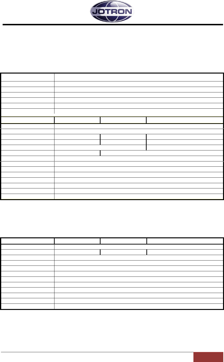
1.1 Models covered by this manual
The following models / variants are covered by this operator’s manual
Model
P/N
Contain units
Output
Frequency
range
Modes
TR-7750C, Transceiver
X-84610
RA-7203C, TA-7650C,
PSU-7002
10 - 50 Watts
156-162 MHz
FM, (G3E)
TA-7650C, Transmitter
X-84555
TA-7650C,
PSU-7002
10 - 50 Watts
156-162 MHz
FM, (G3E)
RA-7203C, Receiver
X-84550
RA-7203C
N/A
156-162 MHz
FM, (G3E)
Table 1.1-1, Radio models
Throughout this manual the term transmitter unit, TX, TA-7650C refers to the transmitter unit.
The term transceiver, TR, TR-7750C refers to any variant of the transceiver unless specifically noted
in the text and the term receiver, RX and RA-7203C is used for the receiver unit.
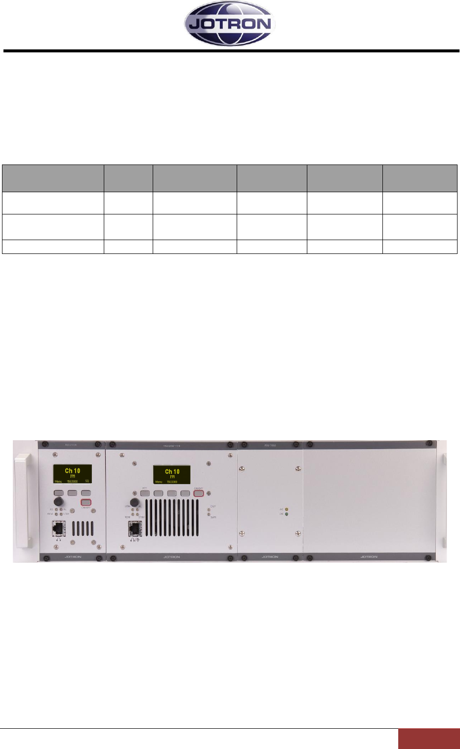
1.2 Layout of the transceiver
The receiver unit, RA-7203C operates as an independent receiver. The transmitter unit TA-7650C
operates as an independent transmitter, but requires the power supply unit, PSU-7002 for operation
on AC power. The receiver and transmitter units may be placed in entirely different locations or
together when configured as a transceiver.
Figure 1.1, Complete Transceiver, RA-7203C, TA-7650C and PSU-7002

Jotron AS| TR7750C: Operators Manual Introduction
Page 1-2
P/N: 84748 (G)
1.3 Applications
The transmitter TA-7650C and the receiver RA-7203C can be used either as a standalone transmitter
/ receiver for maritime voice or data communication, or combined as a transceiver.
The transmitter / receiver can be operated in the following modes:
Locally as an analogue FM transceiver, with microphone and headphone connected to the
front panel connector,
Connected to a VCS (Voice Control System) using 600-ohm analogue lines for audio, together
with keying in form of in-band tones, external voltages or phantom keying.
In addition the transmitter/receiver has a large range of options for remote control using
Ethernet, serial lines or front panel controls.
Jotron AS| TR7750C: Operators Manual Technical SPECIFICATIONS
Page 2-1
P/N: 84748 (G)
2 Technical SPECIFICATIONS
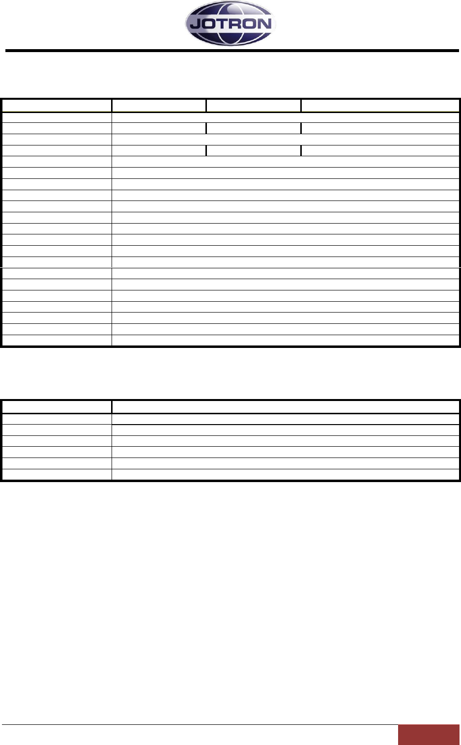
2.1 General specification, Transceiver Units, TR-7750C
Standards
EN 301489-x ,Health and Safety: EN 60950,Radio specifications:EN301929-1 and EN301929-2,FCC part80
Environmental, all units
Temperature range
-20°C to +55°C (operating) -40°C to +70°C (storage)
Humidity
90% @+40°C (non condensing)
Shock
Transport: IEC-721-3-2, Class 2M3
Vibration
Transport: IEC-68-2-32, Class 2M3. IEC-68-2-6
EMC
EN 301 489 – part 22, FCC, IC
General, all units
FM 25 kHz
FM 12.5 kHz
DSC
Frequency range
156-162 MHz , All channels, simplex and duplex within the maritime VHF band is available.
Frequency stability
+/- 1.0 ppm
RF Modes
G3E
G3E
G2B
Keying time
< 1.0ms
< 1.0ms
< 1.0ms
Bit rate
2.4 kbit/s
Frequency response
300-3400 Hz
350-2500 Hz
Data ports
RS232, RS485, 100BaseT
Protocols
Simple Network Management Protocol (SNMP v.2), RS232, RS485; See Protocol description
BITE monitoring
VSWR, Voltages, Currents, Levels, Lock detect,
Temperature, Output power, Reflected power, a.o.
Supply voltage, AC
115/230VAC +15/-10% / 50-60Hz
Supply voltage, DC
21.6 - 31.2VDC negative ground
MTBF
>10 years / unit
MTTR
<30 minutes at lowest replaceable unit
2.2 Transmitter Units, TA-7650C
Transmitter unit
FM 25 kHz
FM 12.5 kHz
DSC
Output power
10-50W
Adjacent channel power
>80dBc
>70dBc
>80dBc
Modulation level
up to ± 5kHz deviation
Distortion
< 3%
Line input
600, -36 - +7dBm
Intermodulation protection
ratio
>40 dB when interfering signal is decoupled with at least 30 dB
Tx timeout
10s to 5 min in 10s steps
Inband keying
Configurable tones: 150 – 3400Hz
VSWR
1 : Infinity
Duty cycle
100% continuous operation @ambient below 40°C
Power consumption
<280VA
Dimension Transmitter nit
142mm(28TE)(W) * 230mm(D) * 128mm (H), Weight 3.0 kg
Jotron AS| TR7750C: Operators Manual Technical SPECIFICATIONS
Page 2-2
P/N: 84748 (G)
2.3 Receiver Unit, RA-7203C
Receiver unit
FM 25 kHz
FM 12.5 kHz
DSC
Sensitivity, FM@1V/30% pd
10dB SINAD (CCITT)
Adjacent channel rejection
>80dB
>80dB
>70dB
Intermodulation (3 signal)
>80 dBc
IF bandwidth
+/- 11kHz
+/- 3.5 kHz
+/- 11 kHz
Image and IF frequency
response
>110 dB
Squelch operation
Adjustable -107dBm, 30dB
S/N + carrier override
Activation time <20ms
Hysteresis <3dB
Audio AGC
30% - 90%, <1dB variation
Signal / Noise
>45dB on any output @100V, 30%
AGC range
-107dBm to +5dBm
Inband squelch signal
User configurable tones: 150 - 3400 Hz
Line output
600, -36 - +7dBm @90% modulation
Harmonic distortion
<5% @90% AM (line output)
Cross modulation
>85dB @ 100 kHz frequency offset
Blocking
>100dB @1MHz offset,>110 dB out of band signals
Dynamic range
>110dB
Spurious response rejection
>90dB
Weight
1.7 kg
Dimension Receiver unit
71mm (14TE)(W) * 230mm(D) * 128mm (H)
2.4 Power Supply Unit, PSU-7002
Power supply unit
Supply voltage, AC
115/230VAC +15/-10% / 50-60Hz
Output voltage
+28 VDC regulated
DC throughput
When AC not present
Max load
10A average, 18A peak (300W)
Dimension PSU unit
71mm (14TE)(W) * 303mm(D) * 128mm (H)
Weight
1.3Kg
Jotron AS| TR7750C: Operators Manual Functional description
Page 3-1
P/N: 84748 (G)
3 Functional description
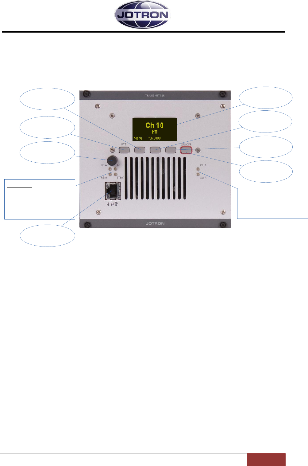
3.1 Front Panel Controls, Transmitter unit
Navigation
button A Display
Navigation
button B
Indicators:
OUT: Output power indicator
SWR: High SWR indicator
PTT button
Scroll / Select
Switch
ON/OFF
button
Navigation
button C
Indicators:
LOW: Transmits in low power
AL: Alarm active (red)
REM: Remote ready (green)
STBY: Standby (yellow)
Mic/Headset
connector
Figure 3.1-1, Front view, transmitter unit, TA-7650C/25C/10C
3.1.1 Display
The display shows the most important operational parameters; Channel, frequency and modulation.
In addition, the display will show several menus, submenus and operational parameters when
entering into the menu using Navigation button A.
3.1.2 Scroll/Select switch and Navigation buttons A, B and C
The navigation buttons, A, B and C, together with the Scroll/Select switch are used to navigate
through the menus.
The Scroll/Select switch has three actions: It can be turned clockwise, anti-clockwise, or momentarily
pressed.
In general the use of the navigation buttons are:
A or Scroll/Select right: Increase a value (up)
B or Scroll/Select left: Decrease a value (down)
C or Scroll/Select press: Confirm or Enter.
The user interface will indicate which navigation button to use.
3.1.3 PTT button
This button is used to immediately key the transmitter for test/measurement purposes, connected
together with the PTT line available on the microphone connector.
3.1.4 ON/OFF button
Press and hold button (for app. 2s) to switch unit ON or OFF.
Jotron AS| TR7750C: Operators Manual Functional description
Page 3-2
P/N: 84748 (G)
3.1.5 LED Indicators
LOW (yellow): The transmitter transmits in low power, either caused by an internal failure
(SWR, Temperature, or low input voltage) or set by the user. The low power
level is adjustable.
AL (red): Indicates that an alarm is present in the transmitter unit. Details of the alarm
will be shown on the display.
REM (green): This LED has multiple functions. The REMOTE indicator will be lit with a
constant green colour when the transmitter is “ready” for remote operation.
Ready means that the keying options has been set to include keying from an
external source, and that the voice input has been set to an external source
(600 ohm line input).
In addition the REMOTE indicator will flash yellow each time the unit is
communicating on either of the remote interfaces (RS232, RS485, Ethernet).
STBY (yellow): The transmitter is kept in standby, either by user input, an external signal to
the remote interface or because an alarm condition has been detected, and
the transmitter is set up as a MAIN transmitter. In standby the transmitter
will not be able to send, even if a valid key signal is input to the unit.
OUT (yellow): Indicate that the transmitter is keyed and power is being generated. The LED
is activated based on RF detected on the output of the power amplifier, thus
the LED gives an indication that power is generated.
SWR (red): Indicate that the SWR on the antenna is above the threshold value (app. 3:1).
The transmitter will reduce the output power to the predefined low power
level in order to protect the output stage.
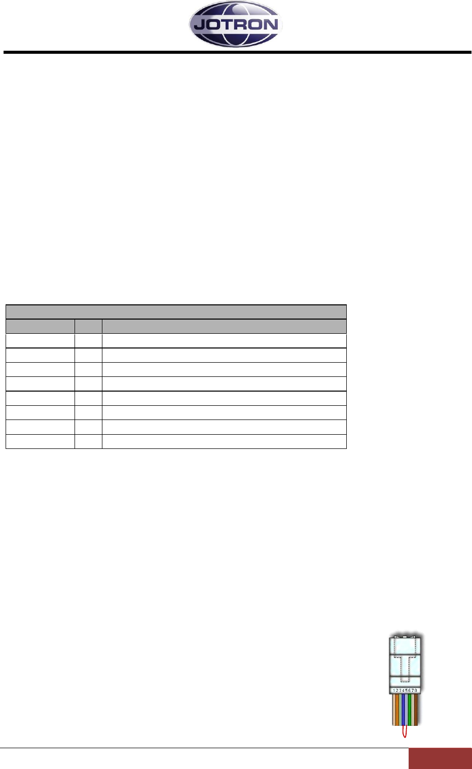
3.1.6 Mic/Headset connector
Table 3.1-1, Mic/Headset connector, transmitter, pin out
The Mic/Headset connector is used for multiple purposes:
Microphone/Headset connector:
Connect the microphone to the Mic input/Mic GND, the +12VDC can be used to power the
microphone or a microphone amplifier. The +12VDC is current limited at 100mA.
The Headset output (referenced to GND) contains the local sidetone generated from the
demodulated signal on the output of the transmitter when the transmitter is keyed, or the
Mic/Headset connector
Name
PIN
Purpose
Mic input
1
Dynamic. Sensitivity 2.5mV nominal.
Mic GND
2
Reference input for mic signal
Headset
3
Headset output, contains sidetone and/or received
audio when used with a receiver (RA7203)
RS232
4
RS232 TX
RS232
5
RS232 RX
PTT
6
PTT input. Connect to GND (p.8) to key
+12VDC
7
+12 VDC to mic. Amplifier (10mA)
GND
8
Common ground

Jotron AS| TR7750C: Operators Manual Functional description
Page 3-3
P/N: 84748 (G)
received audio if the transmitter is connected to a receiver using the T/R bus available on the
rear panels (for details see chapter 3.2.4)
RS232 serial line
The RS232 serial line that can be used to control radio parameters from an external unit, or
to upload new firmware into the radio unit for future functionality. Details regarding
firmware upgrade is described in the maintenance and repair manual.
Hardware key to change access level: In
order to change the access level (see chapter 5.5.3 for details) a hardware
key must be inserted into the microphone/headset connector before
entering in to the menu system. The hardware key consists of a RJ45
connector where pin no. 4 and 5 (RS232 RX and TX) is connected together.
Jotron AS| TR7750C: Operators Manual Functional description
Page 3-4
P/N: 84748 (G)
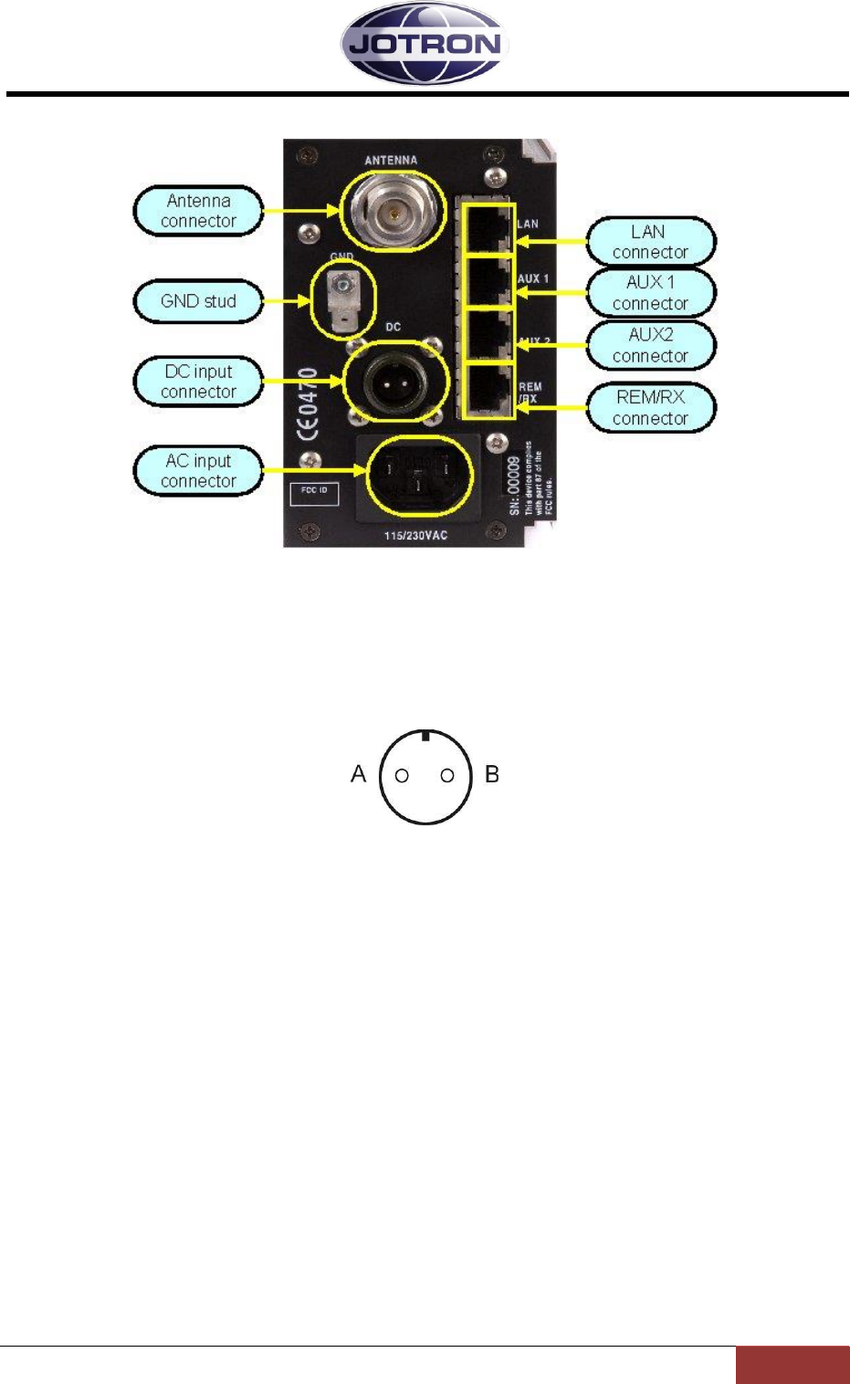
3.2 Transmitter, rear connections
Figure 3.2-1, Rear view, transmitter unit, TA-7650C/25C/10C.
3.2.1 Antenna connector (50 ohm N)
Interface to the antenna cable for the transmitter or the transceiver when used together with a
receiver unit
3.2.2 Receiver ant. Connector (50 ohm BNC)
BNC-Type antenna output – 50 ohm. This connecor is connected to the antenna relay internally in
the transmitter unit and can be connected directly to the antenna input of a mating receiver unit
(RA7203).
3.2.3 DC input connector (Amphenol MS 3106A 10SL4S)(Jotron P/N: 96715)
Figure 3.2-2, Transmitter DC input connector, rear view
Connector for DC supply (21.6 - 31.2 VDC).
Connected to the mating power supply, PSU-7002, or to an external DC supply.
A is the positive (+) connection and B is the negative (-) connection points.

Jotron AS| TR7750C: Operators Manual Functional description
Page 3-5
P/N: 84748 (G)
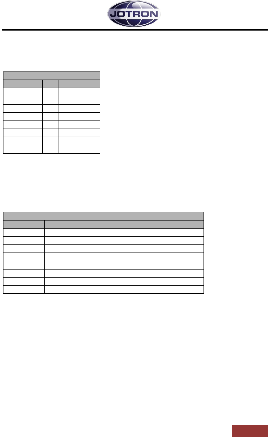
3.2.4 LAN connector (RJ45)
This connector contains the Ethernet bus and is normally connected to a nearby switch/hub or
directly to a computer, using a screened twisted pair Ethernet cable.
LAN interface connector
Name
PIN
Purpose
LAN_TXP
1
Tx data
LAN_TXN
2
Tx data
LAN_RXP
3
Rx data
LAN_D3P
4
Optional
LAN_D3N
5
Optional
LAN_RXN
6
Rx data
LAN_D4P
7
Optional
LAN_D4N
8
Optional
Table 3.2-1, LAN interface connector, pin out
3.2.5 AUX1 CONNECTOR (RJ45)
This connector is normally connected to equipment used for remote control / remote supervision of
the transmitter.
AUX1 connector, transmitterAUX
Name
PIN
Purpose
ALARM_P
1
Alarm out-relay (NO)
ALARM_N
2
Alarm out-relay (NO)
Select_in_P
3
Select in, optocoupler input
RS232_S
4
RS232 Transmit data
RS232_R
5
RS232 Receive data
Select_in_N
6
Select in, optocoupler input
+12V
7
+12VDC output to external equipment (max 300mA)
GND
8
Common ground
Table 3.2-2, AUX1 connector, transmitter, pin out
Jotron AS| TR7750C: Operators Manual Functional description
Page 3-6
P/N: 84748 (G)
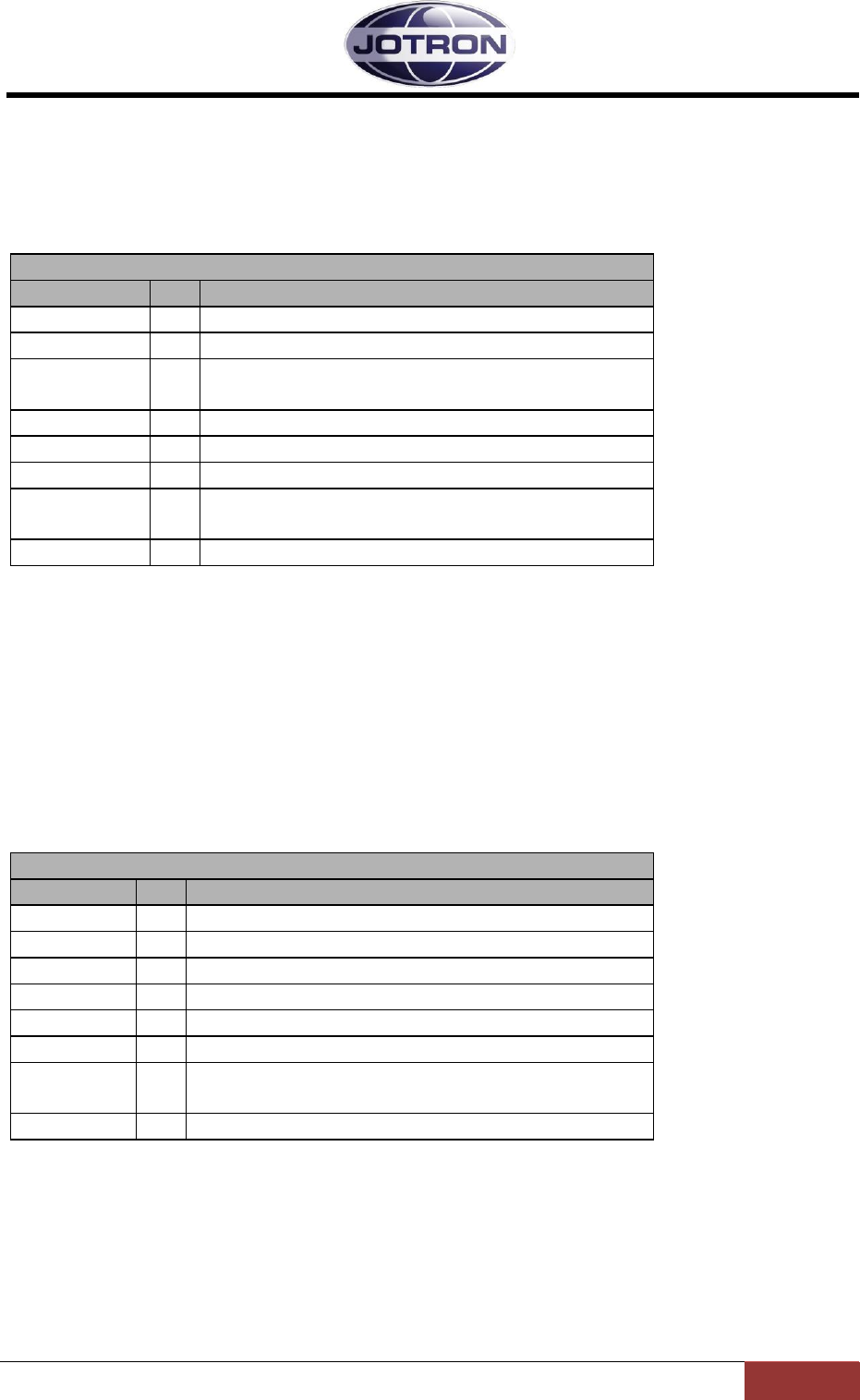
3.2.6 AUX2 connector (RJ45)
This connector is normally connected to equipment used for remote control / remote supervision of
the transmitter.
AUX2 connector, transmitter
Name
PIN
Purpose
KEY_OUT_P
1
Closed=Transmitting, optocoupler output
KEY_OUT_N
2
Closed=Transmitting, optocoupler output
MONITOR_P
3
Monitor output to tape recorder
TXLOW_P
4
Applying a voltage > 5VDC between pin 4 and 5
forces the transmitter into low power
TXLOW_N
5
Applying a voltage > 5VDC between pin 4 and 5
forces the transmitter into low power
MONITOR_N
6
Monitor output to tape recorder
TXKEY_P
7
Applying a voltage > 5VDC between pin 7 and 8 will
key the transmitter
TXKEY_N
8
Applying a voltage > 5VDC between pin 7 and 8 will
key the transmitter
Table 3.2-3, AUX2 connector, transmitter, pin out
3.2.7 REM connector (RJ45)
This connector is normally connected to equipment used for remote control / remote supervision of
the transmitter. It contains the most basic interfaces used for remote control, and will in many cases
be the only connector used.
Note that this connector will also have the most basic functionality for remote controlling the
receiver when the Rx connector is connected to the REM connector on a receiver. In this case the
line, and squelch out signals from the receiver are reflected also on the REM connector.
REM connector, transmitter – Remote control of transceiver
Name
PIN
Purpose
RS485+
1
RS485 (+)
RS485-
2
RS485(-)
LINE_P
3
Diff. line input/output to TA/RA, 600 ohm
TX_KEY_G
4
Grounding this pin will key transmitter
RX_BUSY_OUT
5
RX Busy indicator output (squelch indicator)
LINE_N
6
Diff. line input/output to TA/RA, 600 ohm
ALARM
7
Low=Alarm (TA or TA/RA)
GND
8
Common ground
Table 3.2-4, REM connector, transmitter, pin out
5
6
7
8
9

Jotron AS| TR7750C: Operators Manual Functional description
Page 3-7
P/N: 84748 (G)
3.2.8 Rx connector (RJ45)
This connector is normally connected to the REM connector on a mating receiver when used in a
transceiver configuration.
It gives functionality to a transceiver such as: Common 2 wire line interface, received audio in
transmitter local headset, transceiver alarm, TX/RX busy signalling when used as a VDL modem.
Rx connector, transmitter. Interface to RX (transceiver config)
Name
PIN
Purpose
RS485+
1
RS485 (+)
RS485-
2
RS485(-)
LINE_P
3
Diff. line input from Receiver unit, 600 ohm
TX_BUSY
4
TX Busy indicator output (Mute output)
RX_BUSY
5
RX Busy optocoupler-input (Repeater key input)
LINE_N
6
Diff. line input from Receiver unit, 600 ohm
INT_ALARM
7
Low=Alarm (Note: I/O – low input will also be
recognized as an alarm (EXT))
GND
8
Common ground
Table 3.2-5, Rx connector, transmitter, pin out
Jotron AS| TR7750C: Operators Manual Functional description
Page 3-8
P/N: 84748 (G)
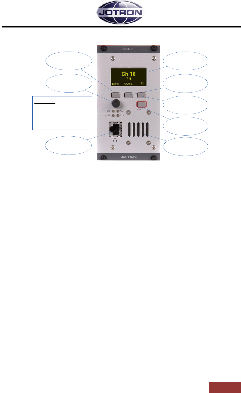
3.3 Front Panel Controls, Receiver unit
Navigation
button A Display
Navigation
button B
Scroll / Select
Switch
ON/OFF
button
Sq / Navigation
button C
Indicators:
SQ: Squelch open (yellow)
AL: Alarm active (red)
REM: Remote ready (green)
STBY: Standby (yellow)
Headset
connector Loudspeaker
Figure 3.3-1, Front view, receiver unit, RA-7203C
3.3.1 Display
The display shows the most important operational parameters; Channel, frequency and modulation.
In addition, the display will show several menus, submenus and operational parameters when
entering into the menu using Navigation button A.
3.3.2 Scroll/Select switch and Navigation buttons A, B and C
The navigation buttons, A, B and C, together with the Scroll/Select switch are used to navigate
through the menus.
The Scroll/Select switch has three actions: It can be turned clockwise, anti-clockwise, or momentarily
pressed in.
In general the use of the navigation buttons are:
A or Scroll/Select right: Increase a value (up)
B or Scroll/Select left: Decrease a value (down)
C or Scroll/Select press: Confirm or Enter.
The user interface will indicate which navigation button to use.
Navigation button C is dedicated to squelch ON/OFF button in the default view.
3.3.3 ON/OFF button
To switch the unit ON or OFF: Press and hold button for approx 2s
3.3.4 LED Indicators
SQ (yellow): The receiver squelch is open (receiving audio) when lit.
Jotron AS| TR7750C: Operators Manual Functional description
Page 3-9
P/N: 84748 (G)
AL (red): Indicates that an alarm is present in the receiver unit. Details of the alarm
will be shown on the display.
REM (green): This LED has multiple functions. The REMOTE indicator will be lit with a
constant green colour when the receiver is “ready” for remote operation.
Ready means that the audio is output to an external source (600 ohm line
input).
In addition the REMOTE indicator will flash yellow each time the unit is
communicating on either of the remote interfaces (RS232, RS485, Ethernet).
STBY (yellow): The receiver is kept in standby, either by user input, an external signal to the
remote interface or because an alarm condition has been detected, and the
receiver is set up as a MAIN receiver. In standby the receiver will not output
any audio on any audio interface.
3.3.5 Headset connector
Table 3.3-1, Headset connector, receiver, pin out
The Headset connector is used for multiple purposes:
Headset connector:
The Headset output (referenced to GND) contains the received audio.
RS232 serial line
The RS232serial line that can be used to control radio parameters from an external unit, or to
upload new firmware into the radio unit for future functionality. Details regarding firmware
upgrade is described in the maintenance and repair manual.
Hardware key to change access level: In
order to change the access level (see chapter 5.5.3 for details) a
hardware key must be inserted into the microphone/headset connector before
entering in to the menu system. The hardware key consists of a RJ45
connector where pin no. 4 and 5 (RS232 RX and TX) is connected
together.
Mic/Headset connector
Name
PIN
Purpose
N/C
1
No connection
N/C
2
No connection
Headset
3
Headset output contains received audio.
RS232
4
RS232 TX
RS232
5
RS232 RX
N/C
6
No connection
+12VDC
7
+12 VDC to external amplifier (10mA)
GND
8
Common ground
Jotron AS| TR7750C: Operators Manual Functional description
Page 3-10
P/N: 84748 (G)
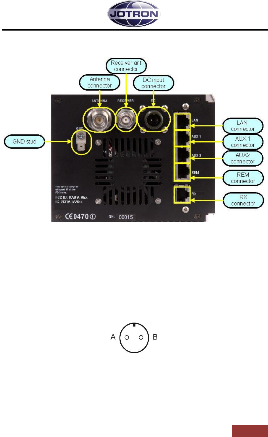
3.4 Receiver, rear connections
Figure 3.4-1, Rear view, receiver unit, RA-7203C.
3.4.1 Antenna connector (50 ohm N)
Connect directly to a receiver antenna, or to the receiver antenna connector (BNC) on the
transmitter unit.
3.4.2 DC input connector (Amphenol MS 3106A 10SL4S)(Jotron P/N: 96715)
Figure 3.4-2, Receiver DC input connector, rear view
Connector for DC supply (21.6 - 31.2 VDC).
Connect to an optional external DC supply to operate the unit on DC or as a backup supply if the
main AC fails.
A is the positive (+) connection and B is connected to ground or chassis (-).
Jotron AS| TR7750C: Operators Manual Functional description
Page 3-11
P/N: 84748 (G)
3.4.3 LAN connector (RJ45)
This connector contains the Ethernet bus and is normally connected to a nearby switch/hub. It can
also be connected directly to a computer, using a twisted pair Ethernet cable.
LAN interface connector
Name
PIN
Purpose
LAN_TXP
1
Tx data
LAN_TXN
2
Tx data
LAN_RXP
3
Rx data
LAN_D3P
4
Optional
LAN_D3N
5
Optional
LAN_RXN
6
Rx data
LAN_D4P
7
Optional
LAN_D4N
8
Optional
Table 3.4-1, LAN interface connector, pin out
3.4.4 AUX1 CONNECTOR (RJ45)
This connector is normally connected to equipment used for remote control / remote supervision of
the receiver.
AUX1 connector, receiver unit
Name
PIN
Purpose
ALARM_P
1
Alarm out-relay (NO)
ALARM_N
2
Alarm out-relay (NO)
Select_in_P
3
Select in, optocoupler input
RS232_S
4
RS232 Transmit data
RS232_R
5
RS232 Receive data
Select_in_N
6
Select in, optocoupler input
+12V
7
+12VDC output to external equipment (max 100mA)
GND
8
Common ground
Table 3.4-2, AUX1 connector, receiver, pin out
Jotron AS| TR7750C: Operators Manual Functional description
Page 3-12
P/N: 84748 (G)
3.4.5 AUX2 connector (RJ45)
This connector is normally connected to equipment used for remote control / remote supervision of
the transmitter.
AUX2 connector, receiver unit
Name
PIN
Purpose
Squelch_out_P
1
Closed=Receiving (Sq open), optocoupler output
Squelch_out_N
2
Closed=Receiving (Sq open), optocoupler output
AGC_HILO_P
3
Hi/Lo output depending on signal strength,
optocoupler output
N/C
4
N/C
5
AGC_HILO_N
6
Hi/Lo output depending on signal strength
AGC_OUT
7
AGC analogue voltage output, depending on signal
strength. Referred to GND
N/C
8
Table 3.4-3, AUX2 connector, receiver, pin out
3.4.6 REM connector (RJ45)
This connector is normally connected to a mating transmitter unit (RX connector) when used in a
transceiver configuration, or to other equipment used for remote control of the receiver.
When connected to a transmitter, the connector gives “transceiver” functionality to the transmitter
and contains necessary signals for audio and control. The TX_BUSY and RX_BUSY signals are also used
in data modes to signal that the transmitter or receiver is busy transferring data.
Interface to Remote equipment or a transmitter unit
Name
PIN
Purpose
RS485+
1
RS485 (+)
RS485-
2
RS485(-)
LINE_P
3
Line output from Receiver unit, 600 ohm
TX_BUSY
4
TX Busy indicator input (Mute input)
RX_BUSY
5
RX Busy output
LINE_N
6
Line output from Receiver unit, 600 ohm
INT_ALARM
7
Low=Alarm (Note: I/O – low input will also be
recognized as an alarm (EXT))
GND
8
Common ground
Table 3.4-4, REM connector, receiver, pin out
5
6
7
8
9
Jotron AS| TR7750C: Operators Manual Functional description
Page 3-13
P/N: 84748 (G)
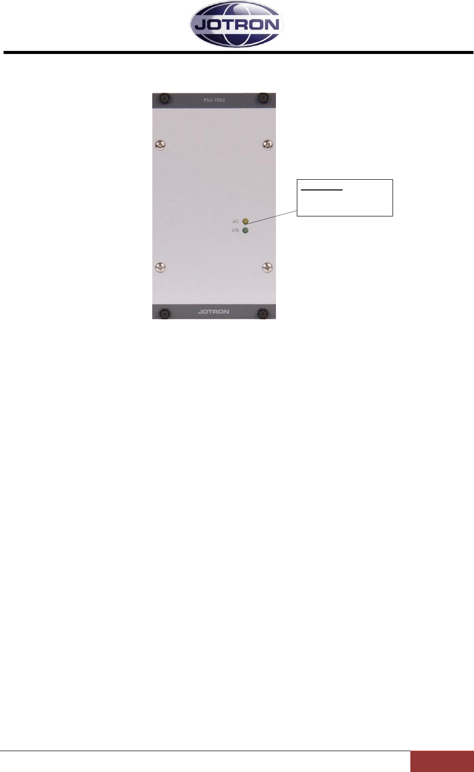
3.5 PSU-7002, Power Supply Unit, frontview
Indicators:
AC: Operating on AC
ON: ON (DC output)
Figure 3.5-1, PSU-7002, front view
3.5.1 LED Indicators
AC (yellow): Indicates that AC is present, and that the unit currently is operating on the
main AC power supply.
ON (green): Indicates that the PSU is ON and delivers DC on its output.
The DC is either derived from the main AC input (shown by the AC indicator),
or from the backup DC input (AC indicator dark).
Jotron AS| TR7750C: Operators Manual Functional description
Page 3-14
P/N: 84748 (G)
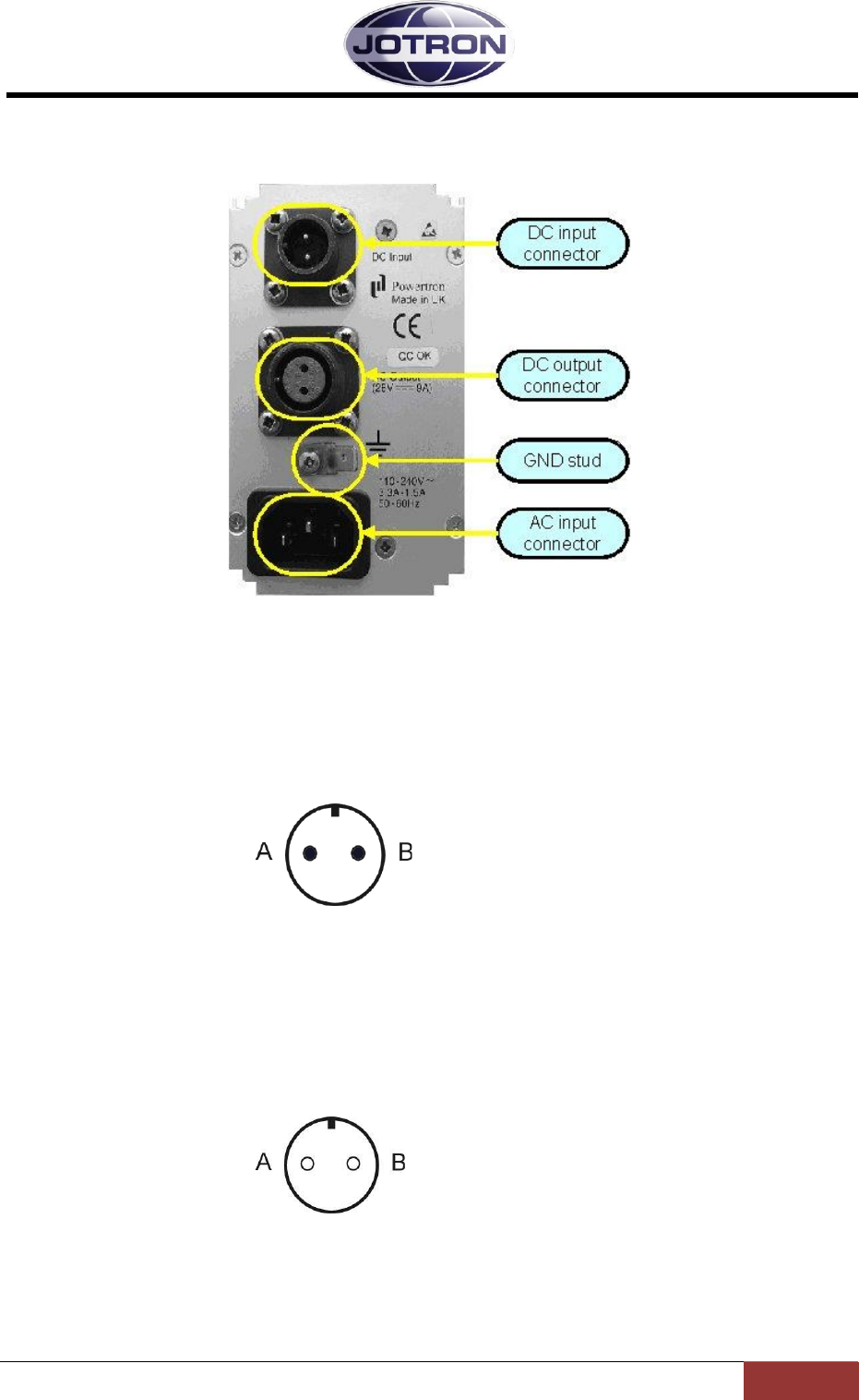
3.6 Power Supply Unit rear connectors.
Figure 3.6-1, Power supply unit - rear view
3.6.1 DC input connector (Amphenol MS 3106A 10SL4S)(Jotron P/N: 96715)
The DC input is connected to the DC backup supply (if available).
Input range is 21.6 - 31.2 VDC and current consumption is max 9A average when the transmitter
operates with full power output (50W).
A is the positive (+) connection and B is connected to ground (-).
Figure 3.6-2, DC input connector, PSU
3.6.2 DC Output Connector(Amphenol MS 3106A 12S3P)(Jotron P/N: 93697)
The DC output connector is connected to the transmitter unit and contains the +28V DC supply for
the transmitter. The DC is generated from the main AC input or the DC backup input.
Figure 3.6-3, DC output, PSU
A is the positive connector pin (+) and B is connected to ground (-).

Jotron AS| TR7750C: Operators Manual Functional description
Page 3-15
P/N: 84748 (G)
3.6.3 AC Input connector
Input for external AC.
AC is input between A and C, B is chassis ground.
The voltage range is from 85 to 250 VAC
Figure 3.6-4, AC input connector, PSU
Jotron AS| TR7750C: Operators Manual Installation
Page 4-1
P/N: 84748 (G)
4 Installation
4.1 Introduction.
The procedures for installing the radio units / transceiver are described in table 4.1 below.
It is recommended that these procedures are completed in the order shown.
Procedure
Reference
1
Initial inspection
4.2
2
Install equipment into 19” sub racks (equipment cabinet)
4.3
3
Connect chassis stud to system earth or cabinet
Figure 3.2-1 (TX)
Figure 3.4-1 (RX)
Figure 3.6-1
(PSU)
4
Connect remote connectors as required
4.6
5
Connect antenna connectors
4.4
6
Connect DC supply (if required)
4.5
7
Connect AC supply (if required
4.5
Table 4.1-1, Installation procedures
4.2 Initial inspection
Items included for a TA-7650C transmitter
P/N
1
Radio unit TA-7650C1
84555
2
Power supply unit PSU-7002
82417
3
Interconnecting cord between TA and PSU
81725
4
CD with Operators guide
84417
5
DC connector
96715
6
AC power cord
92375
Items included for a RA-7203C receiver
P/N
1
Radio unit RA-7203C
84550
2
CD with Operators guide
84417
3
DC connector
96715
4
AC power cord
92375
On receipt of the radio units, remove all transit packaging and check that there is no damage to the
equipment. If damage is evident, contact Jotron immediately and retain the original transit
packaging.
1Variants may include: - Reduced maximum power level <50 W
- PM modulation
- Frequency range 156 – 162MHz
- Inband ptt signalling (option: 84358)
- Inband squelch signalling (option: 84358)
Jotron AS| TR7750C: Operators Manual Installation
Page 4-2
P/N: 84748 (G)
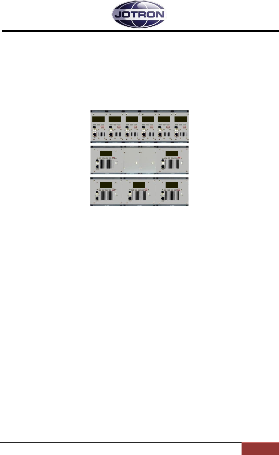
4.3 Installation into equipment cabinet
The units may be installed into a standard 19” subrack with a height of 3U.
The total subrack is divided into 84 TE units. The transmitter occupies 28 TE, the PSU occupies 14TE
and the receiver unit occupies 14TE.
For a transceiver this leaves a free space of 28TE available for other equipment.
Figure 4.3-1 shows some examples for installation into 19” subrack. From top to bottom the figure
shows: 6 receivers in one subrack, 2 transmitters with PSU in one subrack and 3 transmitters without
PSU (operated on DC) in one subrack.
Figure 4.3-1, Examples of various configurations
4.4 Antenna connectors
The antenna should be of good quality with regards to gain and VSWR to obtain maximum
performance. Recommended antennas can be Procom CXL-2-1LW/H (0dBd), Procom CXL-2-3C/M
(3dBd) or similar. Make sure that the VSWR on the antenna is low, and that the cable from the
transmitter to the antenna is of good quality to avoid mismatch and unnecessary losses. The antenna
used with this radio should be installed at least 260cm away from any area where people are likely to
be.
A cable loss of 1 dB is the same as reducing the power output of a 50W transmitter to less than 40W.
Similarly, a cable loss of 2 dB is the same as reducing the output power to less than 32W.
In areas were thunderstorms and lightning is a problem, surge arrestors should be mounted between
the antenna connector and the antenna cable. The arrestors should be of good quality and be
capable of handling the output power of the transmitter.
The antenna output of the transmitter is an N-type antenna connector on the back of the
transmitter. The second connector (BNC-type) is the output of the antenna switch and can be used to
connect the input of a receiver.
4.5 AC and DC connectors
Refer to section 3.4.2, 3.6.1 and 3.6.3 for voltages and connectors.
4.6 Remote signals
Several remote signals are available on the rear interfaces of the radio units.
These signals can be grouped into: Audio signals, Key signals, Data interface signals and other signals.
Note, for all interface signals, RJ45 connectors are used. As far as practically possible, the pairs used
on a standard ethernet connection are used when a signal is input/output as a pair to the radio (e.g.
audio lines). For interconnections between the transmitter and receiver, and for interconnection to a

Jotron AS| TR7750C: Operators Manual Installation
Page 4-3
P/N: 84748 (G)
distribution panel with RJ45 connectors, standard Cat5E, ethernet cable should be used. This is a
good quality, screened cable, with 1 to 1 connections between the two connectors.
Below is an overview of the signals available and their primary use. Refer to chapter 3.2 and 0 for and
overview of the different connectors.
4.6.1 REM connector (receiver) and RX connector (transmitter)
TX - REM/RX RX - REM PIN NAME DESCRIPTION
Pin no Pin no
1 1
RS485+ RS485 - serial communication
2 2
RS485- RS485 - serial communication
3 3
LINE_P RX Audio 600ohm balanced
4 4
TX BUSY TTL L=transmitting (RX pullup)
5 5
RX BUSY TTL L=receiving (TX pullup)
6 6
LINE_N RX Audio 600ohm balanced
7 7
ALARM Alarm (TTL) I/O TRX alarm
8 8
GND Ground
CABLE
4 pairs
RJ45 - Cat 5E, FTP
Table 4.6-1, Transceiver, transmitter – receiver interconnections
The RX connector on the transmitter unit has a special function, and is normally used only in a
“transceiver” configuration.
When connecting the signals on the transmitter RX connector with the signals on the receivers REM
connector, the following functionality is added to the transmitter and receiver:
The receiver audio line (p.3 and p.6) is input to the transmitter.
This enables the possibility to monitor the audio from the receiver from the transmitter
headphone connector, allowing only one plug to be used for a combined
headset/microphone.
In addition, it enables the possibility to use a 2 wire interface to the transmitters audio input
line for the combined transmitter and receiver audio.
Finally, it enables the functionality to monitor both the transmitted audio and the received
audio on the monitor output (TA-AUX2) line on the transmitter.
A RX Busy signal (p.5) is input to the transmitter from the receiver.
This signal signals the transmitter that the RX is busy. This is used in VDL operation.
A TX Busy signal (p.4) is output from the transmitter to the receiver.
This signal signals the receiver that the TX is busy (transmitting). This is used in VDL
operation, and to mute the receiver while transmitting (see table below).
A receiver alarm in/out is connected to the transmitter alarm in/out.
This enables the functionality that the complete transceiver (both receiver and transmitter
unit) will enter into alarm state if one of the units fails. This is useful if the complete
transceiver should be switched to a backup transceiver.
The RS485 serial lines from both units are connected in parallel.
This is useful to have only one connection point for the RS485 on the transceiver for remote
control.

Jotron AS| TR7750C: Operators Manual Installation
Page 4-4
P/N: 84748 (G)
Jotron AS| TR7750C: Operators Manual Installation
Page 4-5
P/N: 84748 (G)
Menu path:
Interface config ►
Parameter
Range
Default
Details
RS485
(TX and RX)
Bitrate
1200 – 115200
1200
Set the bit rate to use on the RS485 port
RS485
(TX and RX)
Address
1 – 255
1
Set the address to use on the RS485. In a
remote system using the RS485
communication port, all units that are
interconnected need to have a unique
address in order to avoid collisions and
misinterpretation of data.
RS485
(TX and RX)
Protocol
Legacy |
standard
Legacy
The protocols are described in the data
manual.
Legacy uses a protocol where the 9. bit is
used for address recognition, this is the
protocol used on the previous radio models
(TA7450, RA7202) and is compatible with
the RACS II PC software and the RCU
remote control unit.
Standard is an eight bit protocol that uses
the multidrop capability of the RS485 bus.
For more information on protocols, refer to
the SW manual.
Menu path:
RX config ►
Parameter
Range
Default
Details
Audio
( RX)
Mute on transmit
False | True
True
Set this to true if the receiver should be
muted while transmitting. Requires that the
Tx busy signal on the transmitters RX
connector is routed to the TX busy input on
the receiver REM connector. (p.4)
Table 4.6-2, Settings associated with the transmitter - receiver interconnection
Jotron AS| TR7750C: Operators Manual Installation
Page 4-6
P/N: 84748 (G)
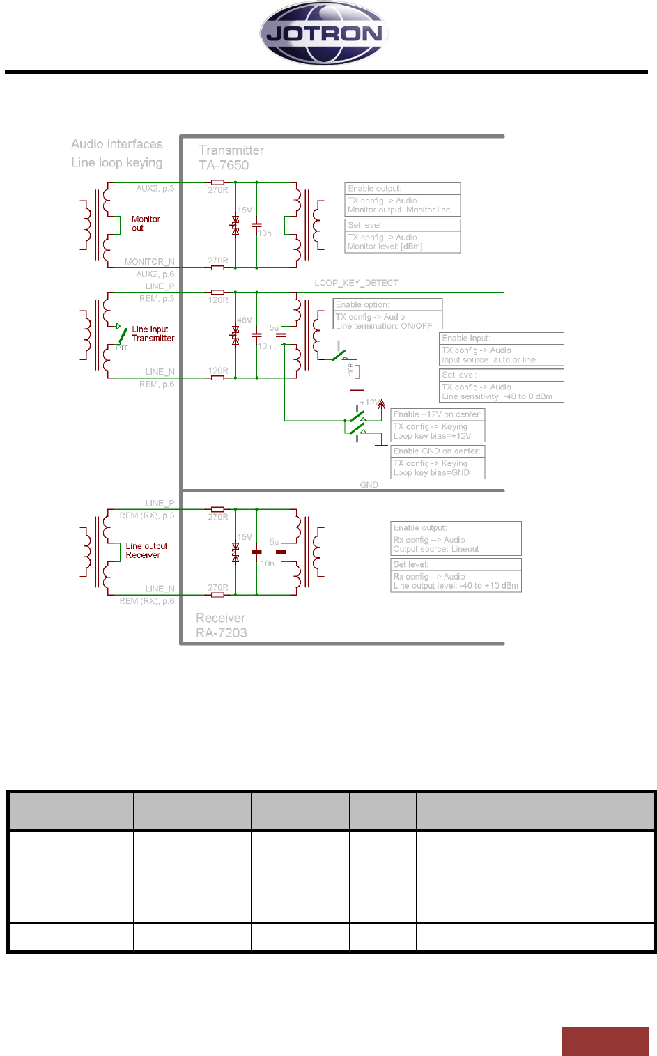
4.6.2 Audio in/out and Line loop keying
Figure 4.6-1, Audio interfaces on the transmitter and receiver units
With reference to
Figure 4.6-1, the following audio remote signals are available on the rear connectors:
Monitor out: Monitor signal, usually connected to a recording unit.
Menu path:
TX config ►
Parameter
Range
Default
Details
Audio
(TX)
Monitor output
Headset |
Monitor output
Monitor
output
Set where the monitor output signal and the
received audio (if a receiver is connected) is
routed.
Can be set to the headset connector, the 600
ohm monitor line output or both.
The monitor signal is the demodulated signal
detected on the output of the transmitter.
Audio
(TX)
Monitor level
-80 – 10 dB
-50 dB
Set the relative output level of the monitor
signal. 10dB = max output, -80dB=minimum
Table 4.6-3, Settings associated with MONITOR OUTPUT (TA – AUX1)

Jotron AS| TR7750C: Operators Manual Installation
Page 4-7
P/N: 84748 (G)
Line input, transmitter: This is the transmitter audio line input. This signal is usually
connected to a VCS system or a remote control that uses a 600 ohm line interface.
Menu path:
TX config ►
Parameter
Range
Default
Details
Audio
(TX)
Input source
Auto | Line | Mic
| modgen | VoIP
Auto
The input source determines where the audio
is applied to the transmitter.
Auto: Uses line input for when a
key signal is detected on one of
the remote connectors and mic
input if the key signal is detected
on the front panel connector.
Line: Uses the 600 ohm line
interface as the audio source
Mic: Uses the microphone input as
the audio source
Modgen: Uses the internal
modgen as audio input source – se
also Modgen frequency
VoIP: Uses the IP interface as the
audio source (availability depends
on radio specifications).
Audio
(TX)
Line sensitivity
-40 – 0 dBm
1 dB steps
-17 dBm
Set the sensitivity of the 600 ohm line input.
This setting determines where the VOGAD
(automatic gain control) start to operate.
Thus if it is set to -17 dBm, levels above -17
dBm will be modulated with 85% (default
setting).
For levels below -17 dBm the modulation will
decrease linearly.
Audio
(TX)
Line termination
OFF | 600 ohm
600 ohm
Set the termination of the input line to either
OFF or 600 ohm. Normally this is set to 600
ohm, but can be set to OFF on one of the
radios, if two transmitters are connected in
parallel. This is to maintain the 600 ohm
impedance on the lines.
Audio
(TX)
Line mute level
OFF or
-40 to -10dBm
1 dB steps
OFF
Below this level, the line input will be muted.
Used where noisy lines are connected to the
transmitter to avoid unnecessary noise on
the produced RF signal during periods of
silence (Automatic transmissions; VOLMET,
ATIS)
Keying
(TX)
Source
Mic, line, txkey,
txgnd, inband
Mic, txkey
Determines what signal that will be used as
the source for keying the transmitter.
Any combinations can be set
Mic: Local PTT input from a
microphone, where the PTT is
connected to pin 4 and 8(gnd) on
the Mic/headset connector.
Line: Keying from a phantom
signal on the line input. Pin 3 and 6
on the Rem/TR connector.
Txkey: The transmitter is keyed by
an external voltage on the
TXKEY_P and TXKEY_N input
pins. Signals located on Pin 7 and
8 on the | connector.
Txgnd: The transmitter is keyed by
a signal on the TXKEY_G input pin
Signals are located on Pin 4 and 8
(gnd) on the REM/TR connector.
Inband: The transmitter is keyed
using an inband tone (see also
inband frequency and inband
sensitivity)

Jotron AS| TR7750C: Operators Manual Installation
Page 4-8
P/N: 84748 (G)
Menu path:
TX config ►
Parameter
Range
Default
Details
Keying
(TX)
Loop key bias
+12V, Gnd,
floating
Floating
Connects the center pin of the line input
transformer to:
Floating: The center pin is not
connected. If loop keying is used,
an external voltage must be
applied to pin 3 (REM connector)
in order to key the transmitter
Gnd: The center pin is grounded. If
loop keying is used, an external
voltage must be applied to pin 3
(REM connector) in order to key
the transmitter.
+12V: A 12V DC is supplied on pin
3(REM/TR connector). The
transmitter can be keyed with a
relay (or equivalent) that create a
DC path on the line input pin, pin 3
and 6 (REM/TR connector).
Table 4.6-4, Settings associated with LINE_INPUT (TX-REM)
Line output, receiver: This is the receiver audio line output. This signal is usually connected
to the VCS system or a remote control that uses a 600 ohm line interface.
Menu path:
RX config ►
Parameter
Range
Default
Details
Audio
(RX)
Output source
Speaker |
Headphone |
Lineout |
VoIP
Speaker,
Headphone,
Lineout
The output source determines where the
received audio is output.
Line: Output audio on the 600
ohm line interface
Speaker: Output audio on the
integrated speaker.
Headphone: Output audio to a
headphone connected to the front
panel connector.
VoIP: Output audio on the IP
interface (availability depends on
radio specifications).
Audio
(RX)
Line output level
-40 to +10 dBm
1 dB steps
-10 dBm
Set the maximum output level on the 600
ohm line output.
Table 4.6-5, Settings associated with LINE_OUTPUT (RX-REM)
Jotron AS| TR7750C: Operators Manual Installation
Page 4-9
P/N: 84748 (G)
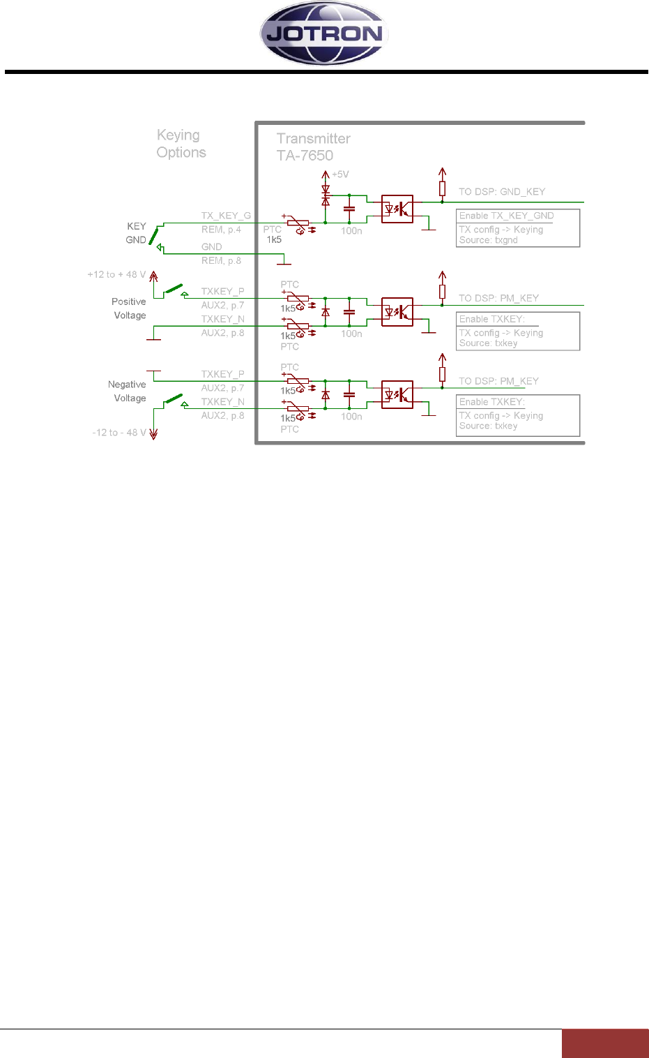
4.6.3 Other key signals
Figure 4.6-2, Key signals on the transmitter unit
In addition to the line loop keying, it is possible to key the transmitter, using several other hardware
and software options.
TX_KEY_G
This is a signal available on the transmitter REM connector, pin 4. This signal, if connected to
GND will key the transmitter.
TXKEY_P, TXKEY_N
This is a differential signal, available on the transmitter AUX2 connector, pin 7 and 8. This
signal will key the transmitter if a voltage between 12 and 48 V is fed between them. Note
also that this is a differential signal, not connected to any ground potential inside the
transmitter, therefore the signal can be configured for both positive and negative voltage
keying (see figure).
Jotron AS| TR7750C: Operators Manual Installation
Page 4-10
P/N: 84748 (G)
Menu path:
TX config ►
Parameter
Range
Default
Details
Keying
(TX)
Source
Mic, line, txkey,
txgnd, inband
Mic, txkey
Determines what signal that will be used as
the source for keying the transmitter.
Any combinations can be set
Mic: Local PTT input from a
microphone, where the PTT is
connected to pin 4 and 8(gnd) on
the Mic/headset connector.
Line: Keying from a phantom
signal on the line input. Pin 3 and 6
on the Rem/TR connector.
Txkey: The transmitter is keyed by
an external voltage on the
TXKEY_P and TXKEY_N input
pins. Signals located on Pin 7 and
8 on the | connector.
Txgnd: The transmitter is keyed by
a signal on the TX_KEY_G input
pin Signals are located on Pin 4
and 8 (gnd) on the REM/TR
connector.
Inband: The transmitter is keyed
using an inband tone (see also
inband frequency and inband
sensitivity)
Table 4.6-6, Key Source settings
Jotron AS| TR7750C: Operators Manual Installation
Page 4-11
P/N: 84748 (G)
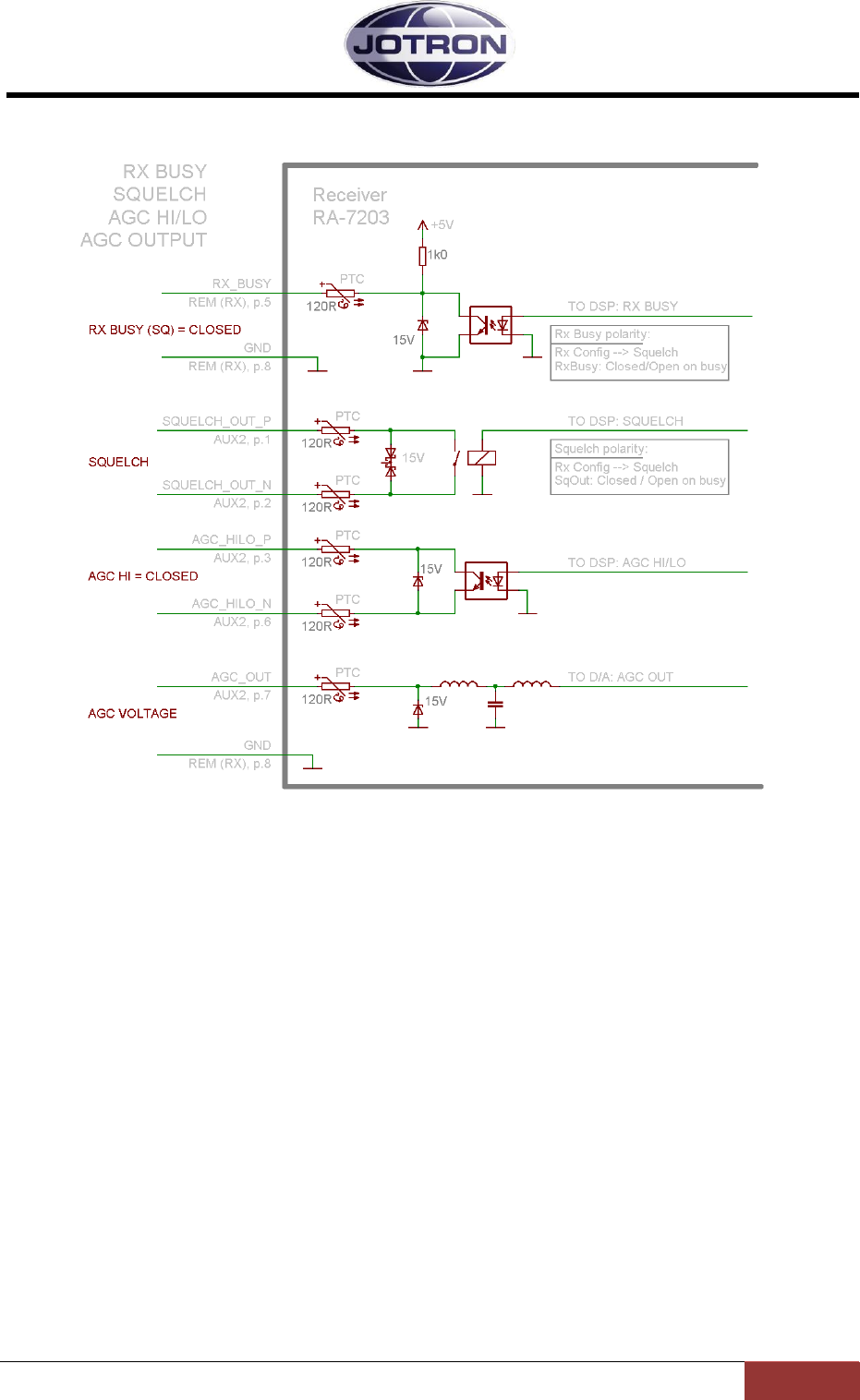
4.6.4 Squelch and AGC signals, receiver unit
Figure 4.6-3, Squelch and AGC signals receiver unit
RX_BUSY (REM, p.5)
Squelch output signal that is referenced to GND.
This signal can be used to detect that the receiver is busy on a connected transmitter unit, on
a remote control or an other unit that can use this signal.
The signal polarity can be configured.
SQUELCH (AUX2, p.1 and p.2)
This signal indicates that the squelch is activated / closed.
The polarity can be configured. The output is a solid state relay, rated for maximum 100V /
100mA.
AGC_HILO_P, AGC_HILO_N (AUX2, p.3 and p.6)
This signal indicates that a signal above approximately +40 dBuV is received.
This can be used to detect if the signal comes from a collocated transmitter operating on the
same frequency or a transmission from an aircraft.
AGC VOLTAGE (AUX2, p.7)
This is an analogue output 0-5V. The output voltage is 0V for an input of xxx uV and increases
linearly with the input signal up to xxx uV where the voltage reach +5V.
Jotron AS| TR7750C: Operators Manual Installation
Page 4-12
P/N: 84748 (G)
Menu path:
RX config ►
Parameter
Range
Default
Details
Squelch
SqOut output
Closed | Open |
Closed on busy|
Open on busy
Closed on
busy
Set the behavior of the SqOut output (AUX2,
pin 1 and pin 2).
Squelch
RxBusy output
Closed | Open |
Closed on busy|
Open on busy
Closed on
busy
Set the behavior of the RxBusy output
(REM, pin 5).
Table 4.6-7, Squelch output configuration
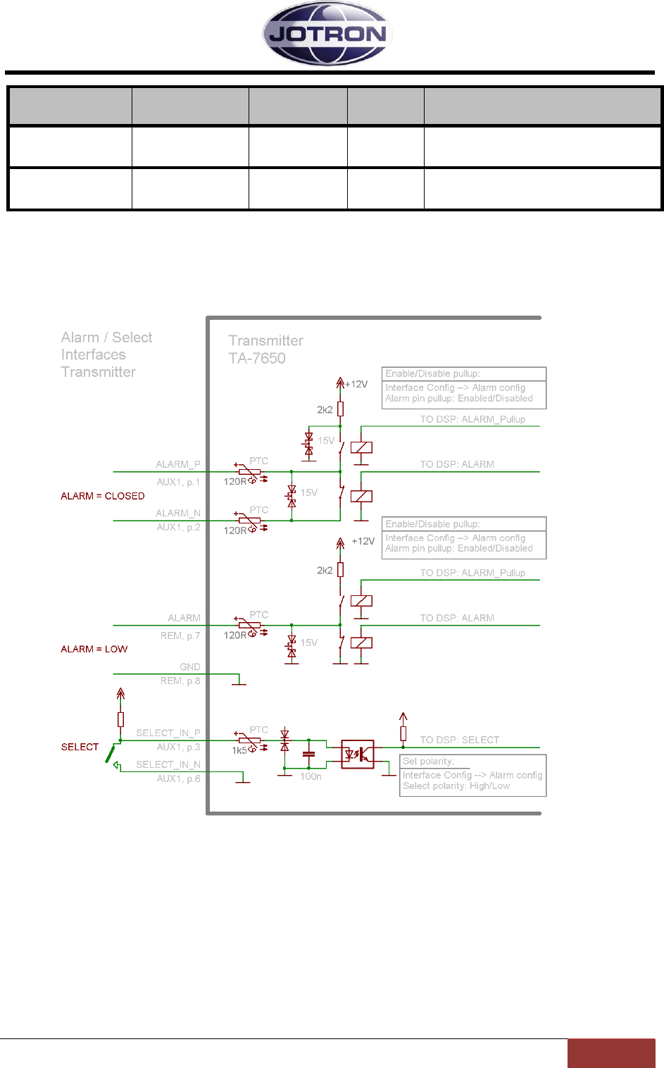
4.6.5 Alarm and Select signals transmitter and receiver
Figure 4.6-4, Alarm and select signals, transmitter
The alarm signals are outputs used to signal that the radio units has detected an alarm internally. The
Select signal is used to select or deselect (inhibit) a particular unit. By deselecting a unit, the unit will
enter into standby and can not be used for radio communication. However, all other functionality of
the radio units is operational when the radio is in the standby state.
The pinout and signals are equal on the transmitter and the receiver unit, except the ALARM (REM,
p.7) pin. This pin has a fixed +5V pull-up on the receiver, while the pull-up is configurable on the
transmitter.
Jotron AS| TR7750C: Operators Manual Installation
Page 4-13
P/N: 84748 (G)
ALARM_P, ALARM_N (AUX1, pin 1 and 2)
This is a differential signal, used to signal the alarm state. The radio can be set up with an
internal pull-up to +12V if desired.
ALARM (REM, pin 7)
Same as the signal above, but this signal is referenced to GND.
SELECT (AUX1, pin 3 and 6)
This input is connected to an optocoupler. The SELECT requires an external voltage to
operate.
One way to use the SELECT signal is in conjunction with the ALARM output signal from
another radio unit. If the ALARM signal (ALARM_P and ALARM_N) on a primary (main) radio
is connected to the SELECT_P and SELECT_N on a secondary (backup) radio, then automatic
switchover from the main to the standby radio is performed when the main radio detects an
alarm. In this mode, a pull-up is required on the ALARM output from the primary radio.
Menu path:
Interface
config ►
Parameter
Range
Default
Details
Alarm config
(TX and RX)
Alarm pin pull-up
Disabled |
Enabled
Enabled
The ALARM_OUT_P and ALARM_OUT_N
output pins on AUX1 is used to signal that
the radio has an alarm. This parameter
applies a pull up voltage to ALARM_OUT_P
when there are no alarms present. When an
alarm is detected the relay contact close.
Alarm config
(TX and RX)
Select polarity
High | Low
Low
The SELECT_IN_P and SELECT_IN_N
input pins on AUX1 can be used to select /
deselect (Standby) the radio with an
external signal (e.g. alarm from a main
radio). This setting determines if the radio
should be operational on a low select input
signal or a high select input signal.
Table 4.6-8, Alarm and Select settings, transmitter and receiver
Jotron AS| TR7750C: Operators Manual Installation
Page 4-14
P/N: 84748 (G)
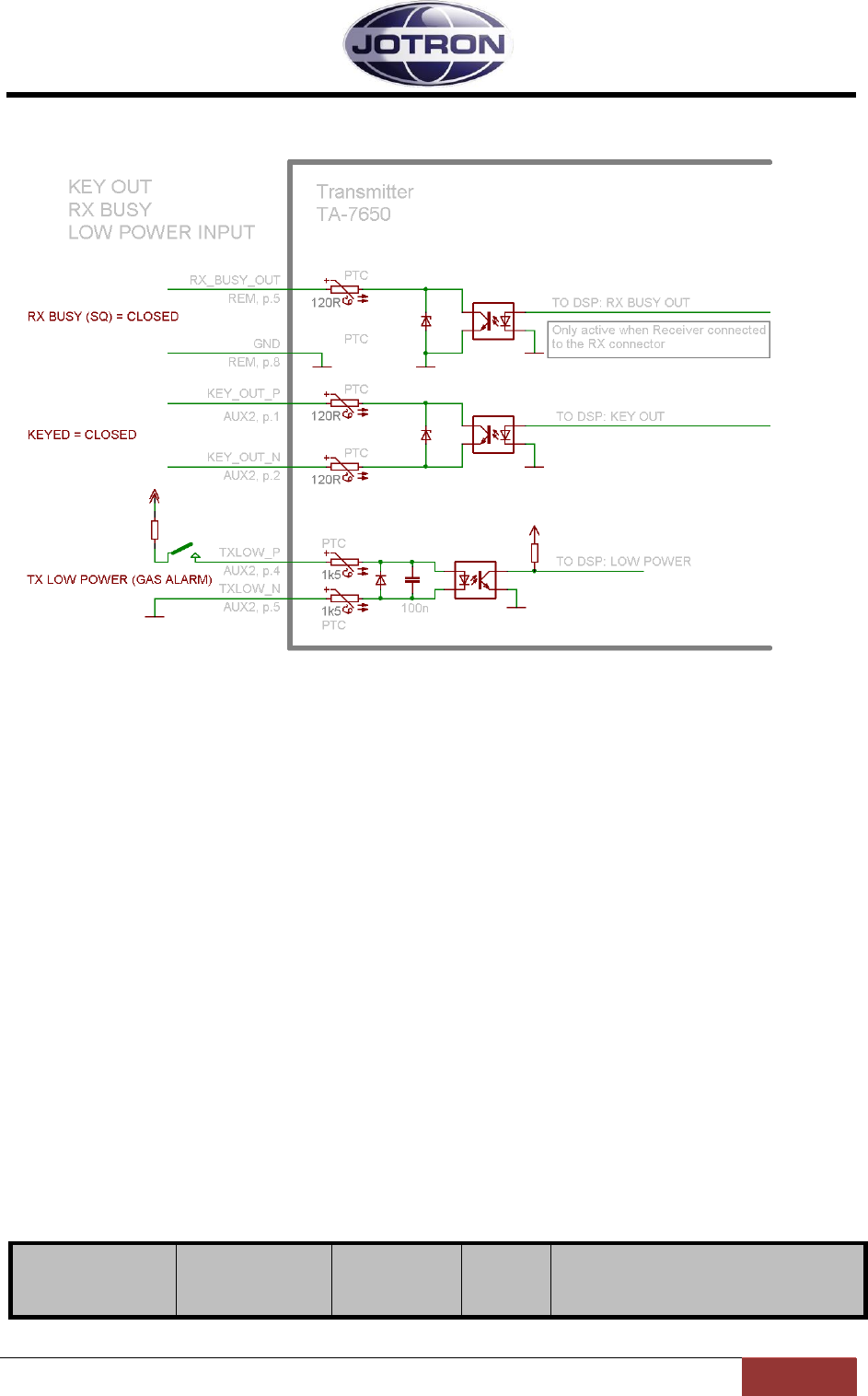
4.6.6 Miscellaneous signals, transmitter
Figure 4.6-5, Misc signals, transmitter
RX BUSY (SQ) (REM, pin 5)
This signal is only available when a receiver is connected with a 8 pin bus between the
transmitter RX and the receiver REM connector.
The signal is the same as the RX BUSY from the receiver, settings are done on the receiver
unit.
KEY_OUT_P, KEY_OUT_N (AUX2, pin 1 and 2)
This output can be used for external equipment that needs a key signal from the transmitter.
The key signal is available immediately after a key input is received on any of the key inputs.
Normally RF is produced only a few ms (<10ms) after a key signal is applied to the
transmitter.
If the KEY_OUT is used for external equipment that used relays for switching the RF, it is
necessary to delay the RF output, this can be done with a software setting, see below.
TXLOW_P, TXLOW_N (AUX2, pin 4 and 5)
This input is used to immediately switch the transmitter into low power. The input requires
an external pull-up to work. The low power level can be adjusted with a software setting.
Menu path:
Radio control
►
Parameter
Range
Default
Details
Jotron AS| TR7750C: Operators Manual Installation
Page 4-15
P/N: 84748 (G)
Menu path:
Radio control
►
Parameter
Range
Default
Details
Low power level
(TX)
30 – 41 dBm
1 dB steps
41 dBm
Set the low power level of the transmitter in 1
dB steps. The low power level is the output
power of the transmitter when the transmitter
is set to low power, either by a command or
by an external input signal.
30 dBm corresponds to 1W output, 41 dBm
is 12W ouput.
Menu path:
TX config ►
Parameter
Range
Default
Details
Keying
(TX)
RF delay
0 – 200 ms
0 (OFF)
This setting is useful when the transmitter is
used together with external equipment such
as T/R relays, power amplifier or other
equipment that includes RF switchover
relays.
Since the RF switching in the transmitter is
done electronically, the RF is produced in
less than 10ms after the PTT signal is
detected. It could be harmful for the external
relays if the RF is applied to them before
switchover has occurred.
In order to delay the RF carrier this
parameter should be used under such
circumstances. A reasonable setting should
be in the order of 40-50 ms.
Table 4.6-9, Misc. settings, transmitter.
4.7 Applications
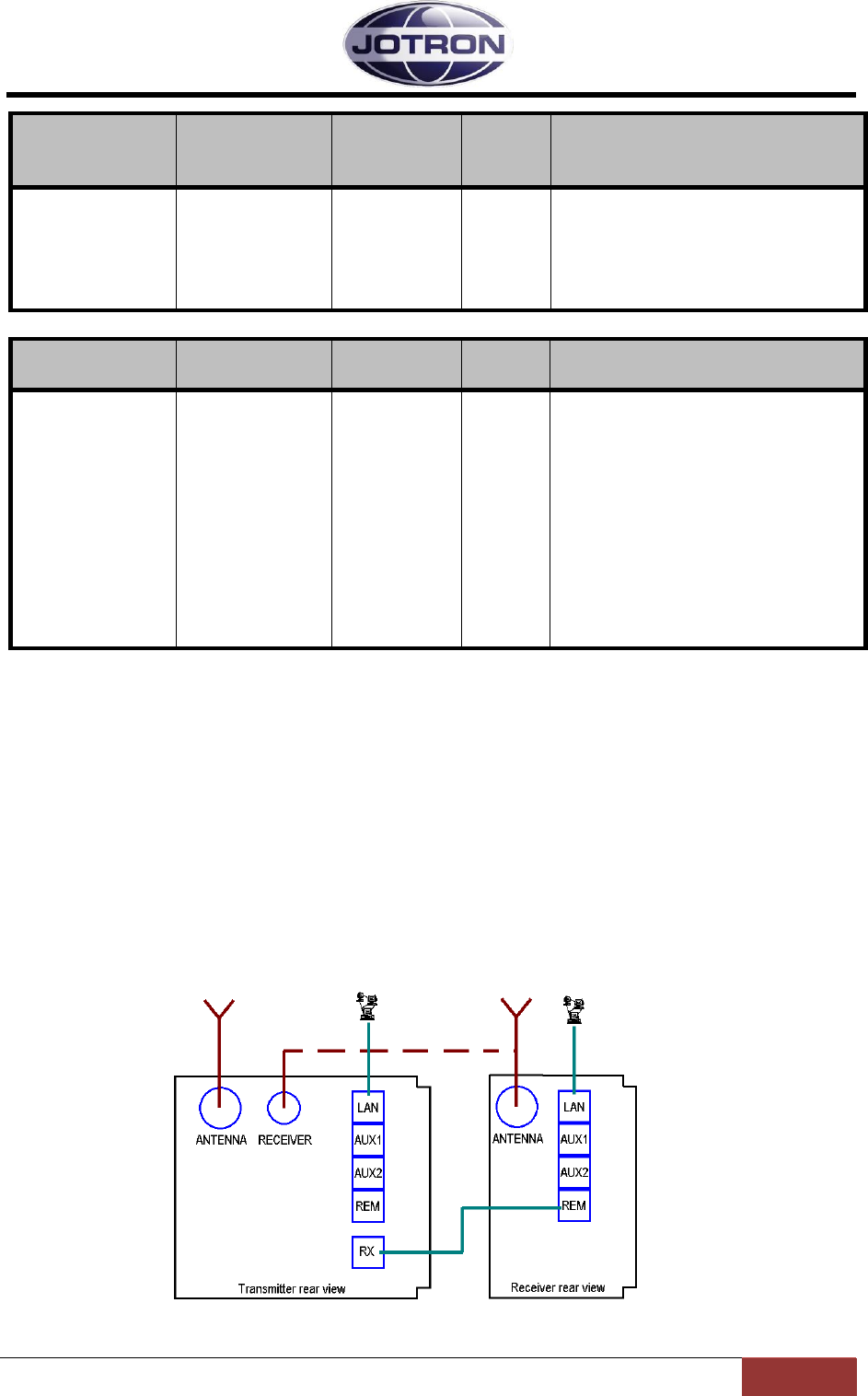
4.7.1 Transceiver, local configuration
In a transceiver setup for local configuration, the mic and headset signals are interfaced to the
microphone/headset connector on the transmitter. The headphone signal can also be derived from
the headset connector on the transmitter.
Connection for local operation is shown in
Figure 4.7-1 and tab.
Figure 4.7-1, Transceiver, Local configuration, interfacing

Jotron AS| TR7750C: Operators Manual Installation
Page 4-16
P/N: 84748 (G)
Jotron AS| TR7750C: Operators Manual Installation
Page 4-17
P/N: 84748 (G)
Step
Description
Reference
1
Connect an 8 wire Cat5e cable between TA-RX connector and RA-
REM connector.
4.6.1 - Pin description
2
Set the Mute on transmit to enabled (receiver)
5.9.2 - RX config group
3
Set Audio output source to Lineout (receiver)
5.9.2 - RX config group
4
Set Audio input source to mic (transmitter)
5.5.2 – TX config group
5
Set Monitor output to headset (transmitter)
5.5.2 – TX config group
6
Set Keying source to include mic (transmitter)
5.5.2 – TX config group
7
Connect a coax cable (RG58 or better) between the TA – Receiver
antenna connector (BNC) and the antenna input on the receiver.
Alternatively, use separate antennas for the TA and RA.
3.2.2 and 3.4.1
Other useful signals in Local configuration:
AUX1
Alarm out, Select in, RS232, +12V
3.2.5 (transmitter AUX1) and
3.4.4 (receiver AUX1)
TA-
AUX2
Key out relay, Monitor output, TX_LOW (Gas alarm) input, TXKEY
3.2.6 (transmitter AUX2)
RA-
AUX2
Squelch out relay, AGC HILO output, AGC voltage output
3.4.6 (receiver AUX2)
TA –
REM
RS485, Line input, Key, Squelch, Alarm
3.2.7 (transmitter REM)
Table 4.7-1, Transceiver, Local configuration
Jotron AS| TR7750C: Operators Manual Installation
Page 4-18
P/N: 84748 (G)
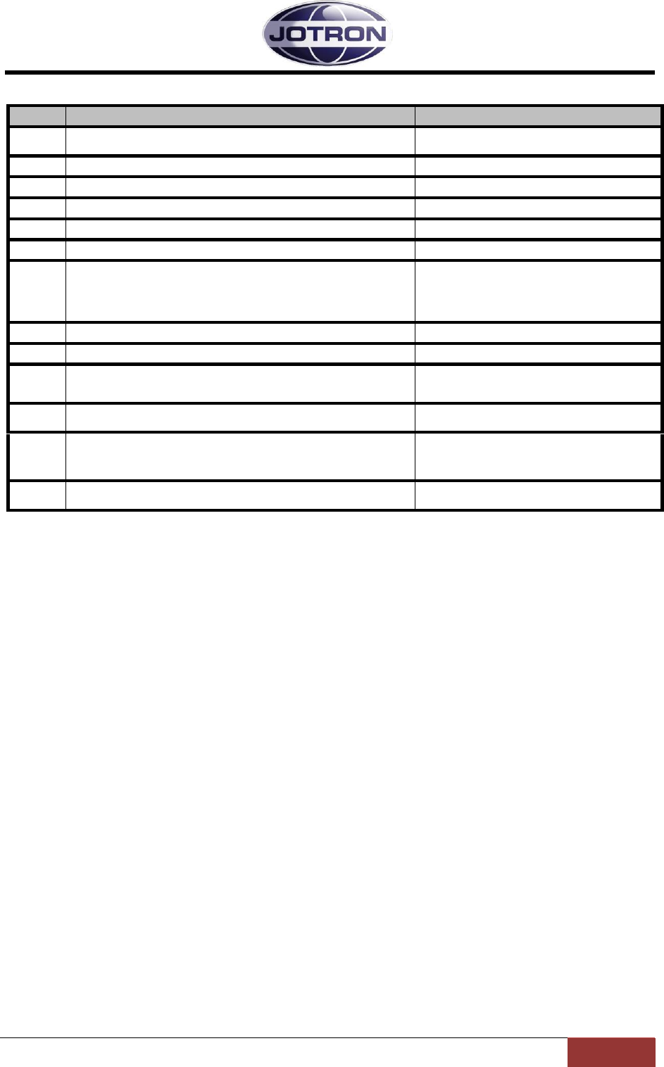
4.7.2 Transceiver, remote configuration
In a transceiver setup for remote configuration, the audio is fed into the transmitter and the received
audio is output from the receiver on the 600 ohm lines.
The line can either be a 2 wire (2W) audio line connected to the transmitter only, or a 4 wire (4W)
interface connected to the transmitter and the receiver units.
Figure 4.7-2, Transceiver, Remote configuration with 2 wire audio interface
Step
Description
Reference
1
Connect an 8 wire Cat5e cable between TA-RX connector and RA-
REM connector.
4.6.1 - Pin description
2
Set Mute on transmit to enabled (receiver) – if desired
5.9.2 - RX config group
3
Set Audio output source to Lineout (receiver)
5.9.2 - RX config group
4
Set Audio input source to line (transmitter)
5.5.2 – TX config group
5
Set Keying source to include txkeygnd
5.5.2 – TX config group
6
Connect a coax cable (RG58 or better) between the TA – Receiver
antenna connector (BNC) and the antenna input on the receiver.
Alternatively, use separate antennas for the TA and RA.
3.2.2 and 3.4.1
Other useful signals in Remote configuration:
AUX1
Alarm out, Select in, RS232, +12V
3.2.5 (transmitter AUX1) and
3.4.4 (receiver AUX1)
TA-
AUX2
Key out relay, Monitor output, TX_LOW (Gas alarm) input, TXKEY
3.2.6 (transmitter AUX2)
RA-
AUX2
Squelch out relay, AGC HILO output, AGC voltage output
3.4.6 (receiver AUX2)
TA –
REM
RS485, Line input, Key, Squelch, Alarm
3.2.7 (transmitter REM)
Jotron AS| TR7750C: Operators Manual Installation
Page 4-19
P/N: 84748 (G)
Table 4.7-2, Transceiver, Remote (2W) interface
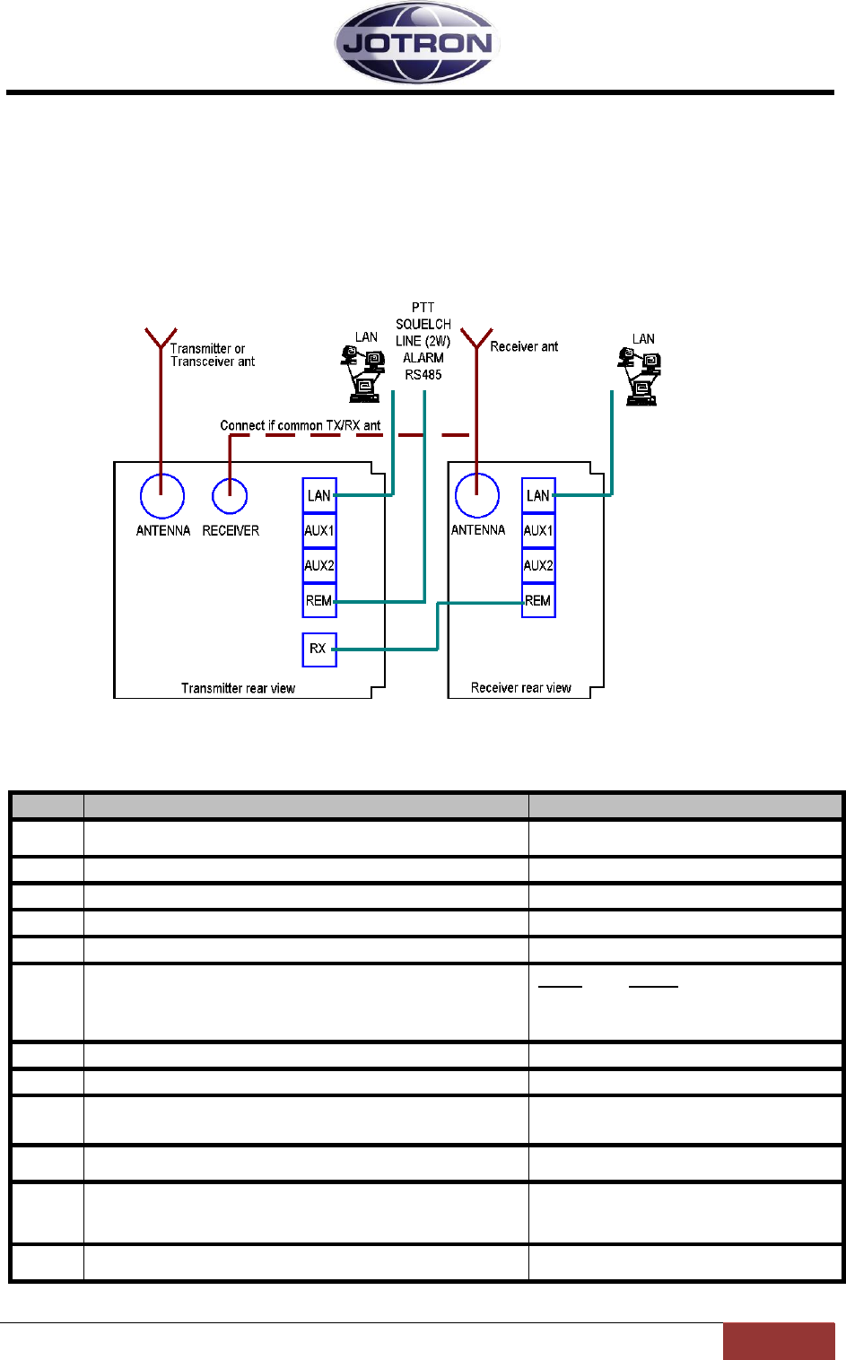
Figure 4.7-3, Transceiver, Remote configuration with 4 wire audio interface
Step
Description
Reference
1
For audio line interfaces refer to the reference
4.6.2 – Audio interface
3
Set Audio output source to Lineout (receiver)
5.9.2 - RX config group
4
Set Audio input source to line (transmitter)
5.5.2 – TX config group
5
Set Keying source to include txkeygnd ( or other signal if
desired)
5.5.2 – TX config group
6
Connect a coax cable (RG58 or better) between the TA – Receiver
antenna connector (BNC) and the antenna input on the receiver.
Alternatively, use separate antennas for the TA and RA.
3.2.2 and 3.4.1

Jotron AS| TR7750C: Operators Manual Installation
Page 4-20
P/N: 84748 (G)
Step
Description
Reference
Other useful signals in Remote configuration:
AUX1
Alarm out, Select in, RS232, +12V
3.2.5 (transmitter AUX1) and
3.4.4 (receiver AUX1)
TA-
AUX2
Key out relay, Monitor output, TX_LOW (Gas alarm) input, TXKEY
3.2.6 (transmitter AUX2)
RA-
AUX2
Squelch out relay, AGC HILO output, AGC voltage output
3.4.6 (receiver AUX2)
TA –
REM
RS485, Line input, Key, Squelch, Alarm
3.2.7 (transmitter REM)
Table 4.7-3, Transceiver, Remote (4W) interface
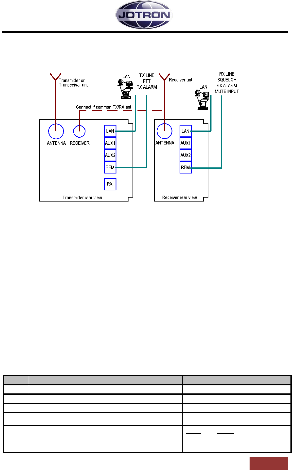
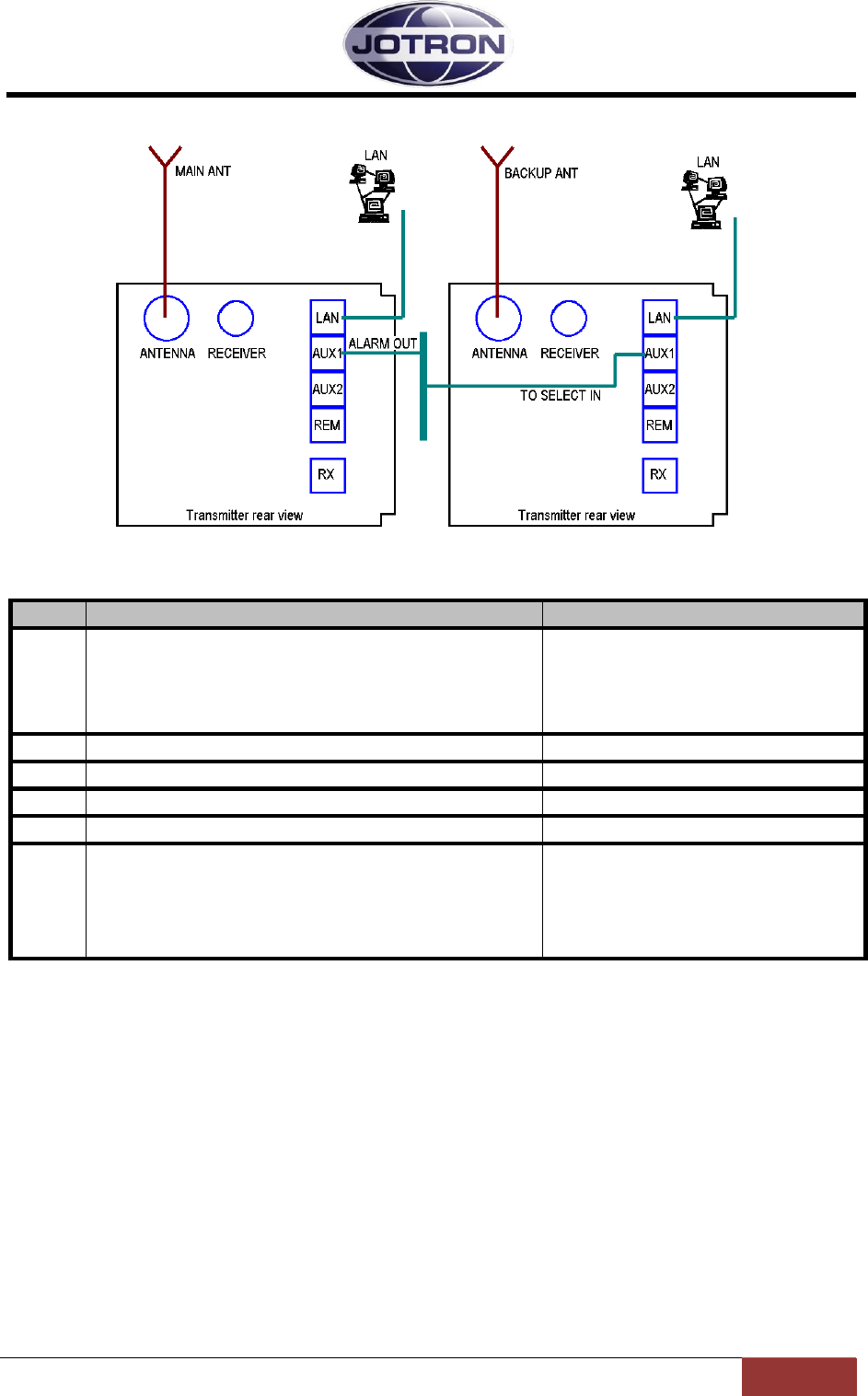
4.7.3 Transmitter, main / backup configuration
By connecting the alarm output from one (main) transmitter to the select input on a backup unit, it is
possible to perform automatic switching between them. In this way, if a main transmitter detects an
internal failure, it can be set up to enter into standby mode and stop transmissions. The alarm signal
will also signal to a backup unit to take over the transmit function.
Jotron AS| TR7750C: Operators Manual Installation
Page 4-21
P/N: 84748 (G)
Figure 4.7-4, Main / Backup transmitter
Step
Description
Reference
1
Connect the alarm_out signal (p.1,2) from AUX1 on the main
transmitter to the select_in signal (p.3.6) on AUX1 on the standby
transmitter. The connection can be done via a distribution panel or
by making a special with RJ45 connectors in each end. The cables
used should be of the same quality as a CAT5E network cable and
the screen should be connected in the plugs.
3.2.5 – AUX1 connector
2
Set Alarm config, Alarm pin pullup to Enabled (default)
5.5.3 – Interface config group
3
Set Alarm config, Select polarity to Low (default)
5.5.3 – Interface config group
4
Set the main transmitter Operation mode to Main
5.5.1 – Radio control group
5
Set the backup transmitter Operation mode to Norm (default)
5.5.1 – Radio control group
6
Connect separate antennas to the two transmitters.
Alternatively use an external antenna change over unit (ACU) in
order to switch the antenna between the main and standby
transmitters. The antenna change over unit can be controlled by
the alarm signal on the main unit
Table 4.7-4, Main/backup configuration, transmitters
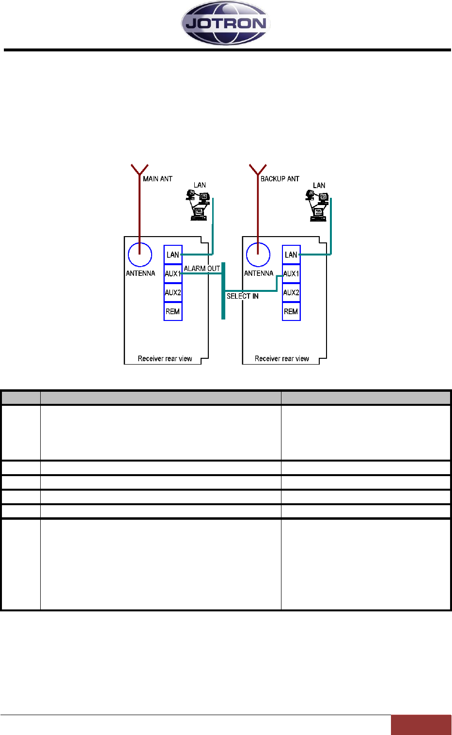
Jotron AS| TR7750C: Operators Manual Installation
Page 4-22
P/N: 84748 (G)
4.7.4 Receiver, main / backup configuration
By connecting the alarm output from one (main) receiver to the select input on a backup unit, it is
possible to perform automatic switching between them. In this way, if a main transmitter detects an
internal failure, it can be set up to enter into standby mode and stop reception of signals. The alarm
signal will also signal to a backup unit to take over the receive function.
Figure 4.7-5, Main / Backup receiver
Step
Description
Reference
1
Connect the alarm_out signal (p.1,2) from AUX1 on the main
receiver to the select_in signal (p.3.6) on AUX1 on the standby
receiver. The connection can be done via a distribution panel or by
making a special with RJ45 connectors in each end. The cables
used should be of the same quality as a CAT5E network cable and
the screen should be connected in the plugs.
3.4.4 – AUX1 connector
2
Set Alarm config, Alarm pin pullup to Enabled (default)
5.8.3 – Interface config group
3
Set Alarm config, Select polarity to Low (default)
5.8.3 – Interface config group
4
Set the main receiver Operation mode to Main
5.8.1 – Radio control group
5
Set the backup receiver Operation mode to Norm (default)
5.8.1 – Radio control group
6
Connect separate antennas to the two receivers.
Alternatively use an external antenna change over unit (ACU) in
order to switch the antenna between the main and backup
receivers. The antenna change over unit can be controlled by the
alarm signal on the main unit.
The antenna connection can also be done via a pair of
main/backup transmitters.
Table 4.7-5, Main/backup configuration, receivers

Jotron AS| TR7750C: Operators Manual Operating Instructions
Page 5-1
P/N: 84748 (G)
5 Operating Instructions
5.1 Introduction
To set up the transmitter and receiver units, several parameters can be selected from the
front panel. This section details how this is done and the range of all parameters.
Since the radio units contains no manual tuning points or switches, all parameters can in
principal be set from the front panel, however except in some rare occasions, most
parameters should be left at their default (factory preset) values.
There are 4 user levels that can be selected to limit the user access to certain parameters.
The user levels can be set on one of the data interface ports. There is also a way to override
the user levels, described in the technical manual.
These user levels are:
Restricted Limits front panel operation to selecting preset channels and adjusting
audio output levels and display appearance. Use this level when the
radio units are used from a remote position or in cases where the
user should be restricted to use preset channels only (1 – 100).
Operation Same as restricted, but in addition the local user has full access to
changing and storing frequencies, and to change the squelch level.
Technician This level gives the local user access to the most used installation
specific parameters (line levels, output power, etc.) and should be
used when installing or maintaining the radio units.
SysOp This level gives unlimited access to all parameters within the radio
units and should be used with care.
In the following section, these symbols and abbreviations are used to explain navigation in
menus / setting of values:
Scroll/Select switch =
Navigation button A (left button) =
Navigation button B (middle button) =
Navigation button C (right button) =
Clockwise = CW
Counter Clockwise = CCW
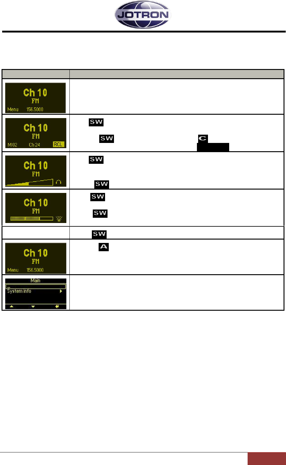
Jotron AS| TR7750C: Operators Manual Operating Instructions
Page 5-2
P/N: 84748 (G)
5.2 User menu – transmitter (Restricted access level)
Main display window in restricted mode.
Display
Description
When the transmitter is switched on, it will show the channel, the
frequency and the operation mode (FM).
Press to navigate to the channel recall screen.
Select any channel (up to 100) that is previously stored in the radio by
rotating . Recall selected channel with
If no channel is stored, the display will show: CH: No channels
Press to navigate to the audio output level screen.
This setting adjusts the audio level output at the front panel
microphone/headset connector.
Rotate CW or CCW to adjust the headset level.
Press to navigate to the display intensity adjust screen.
This setting adjusts the intensity of the display and LED indicators.
Rotate CW or CCW to adjust the intensity.
Press to return to the default screen
Pressing from the main display will bring up the menu options
available for the current user level.
Menus for user level: Restricted
For details regarding submenus, refer to chapter 5.4.
Table 5.2-1, User menu selections transmitter - restriced access level
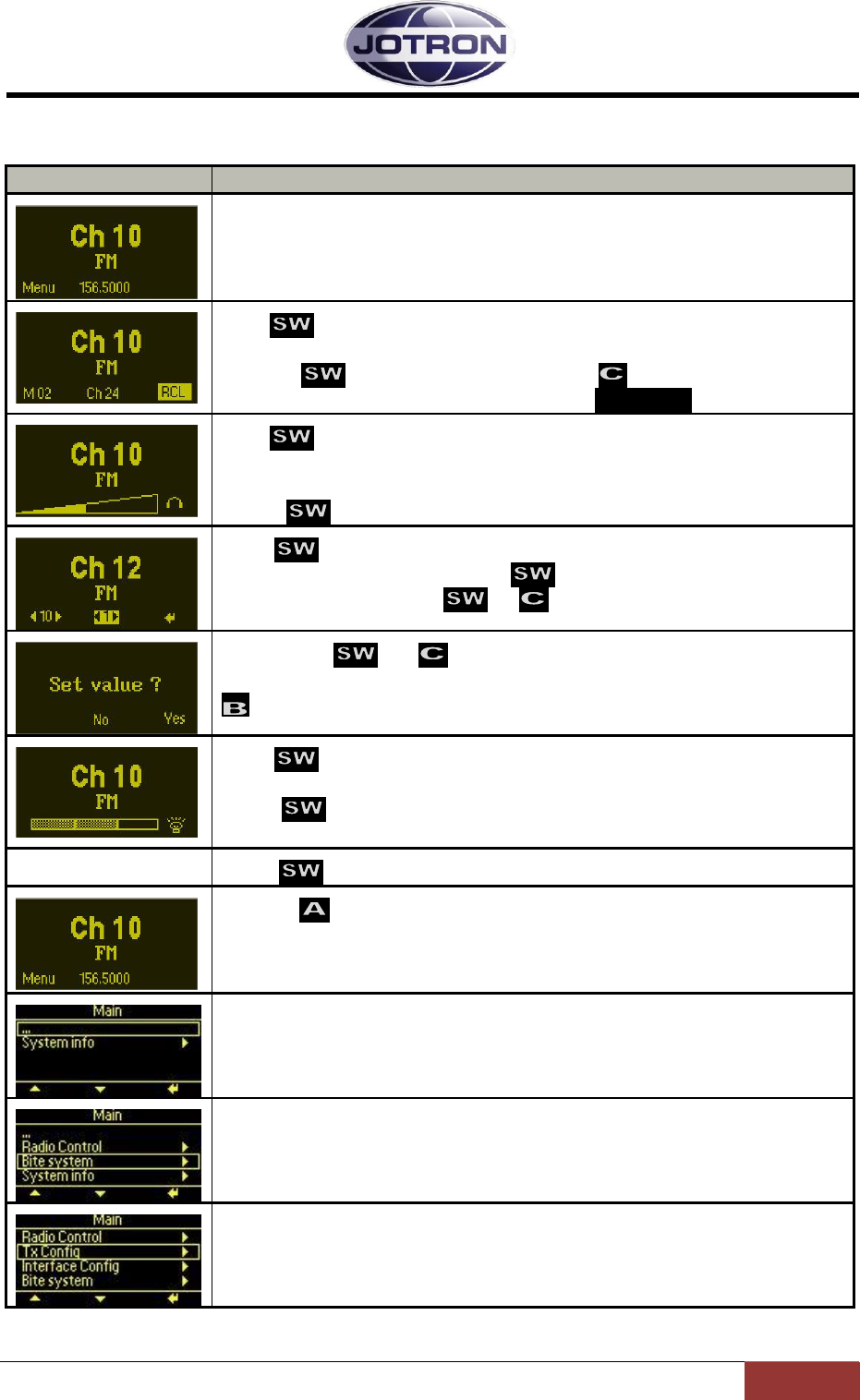
Jotron AS| TR7750C: Operators Manual Operating Instructions
Page 5-3
P/N: 84748 (G)
5.3 User menu – transmitter (Default access level)
Main display window for user levels: Operator, Technician and SysOp.
Display
Description
When the transmitter is switched on, it will show the channel, the
frequency,and the operation mode (FM).
Press to navigate to the channel recall screen.
Select any channel (up to 100) that is previously stored in the radio by
rotating . Recall selected channel with
If no channel is stored, the display will show: CH: No channels
Press to navigate to the audio output level screen.
This setting adjusts the audio level output at the front panel
microphone/headset connector.
Rotate CW or CCW to adjust the headset level.
Press to navigate to the channel select screen.
Select channel number by rotating CW or CCW.
Confirm new channel with or .
Confirm with or .
If the channel is already programmed, the channel may be cleared using
Press to navigate to the display intensity adjust screen.
This setting adjusts the intensity of the display and LED indicators.
Rotate CW or CCW to adjust the intensity.
Press to return to the default screen
Pressing from the main display will bring up the menu options
available for the current user level.
Menus for user level: Operator
For details regarding submenus, refer to chapter 5.4.
Menus for user level: Technician
For details regarding submenus, refer to chapter 5.4.
Menus for user level: SysOp
For details regarding submenus, refer to chapter 5.4.
Table 5.3-1, User menu selections transmitter- Operator, Technician and SysOp access levels
Jotron AS| TR7750C: Operators Manual Operating Instructions
Page 5-4
P/N: 84748 (G)
5.4 Setting, information and configuration menus – transmitter
Under the menu selection from the user menu, various submenu groups are available depending on
the user level.
The submenus and details for them are shown in the tables below.
Submenu
Access level
Description
Radio control
►
SysOp, Technician
Access to operation mode, low power level, climax offset
parameters, modulation and standby settings.
TX config
►
SysOp
Access to configuration parameters for modulation, audio
settings, key (PTT) settings and internal calibration
settings.
Interface config
►
SysOp
Access to configuration parameters for the ethernet interface,
RS232 port, RS485 port, various pin settings on the hardware
interface (remote connectors) and the user access level.
Bite system
►
SysOp, Technician
Displays information about active alarms and gives the
user access to internal measurements.
System info
►
All
Displays information about the firmware and hardware
release, system up-time and radio identification
Table 5.4-1, Submenus available on the transmitter
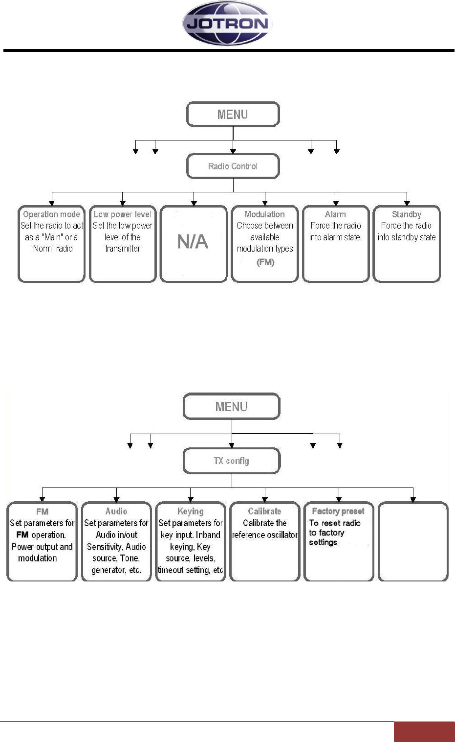
Jotron AS| TR7750C: Operators Manual Operating Instructions
Page 5-5
P/N: 84748 (G)
5.4.1 Radio control group
SysOp and Technician access levels. Refer to section 5.5.1 for details.
Figure 5.4-1, Radio control group, transmitter
5.4.2 TX config group
SysOp access level. Refer to section 5.5.2 for details.
Figure 5.4-2, TX config group, transmitter
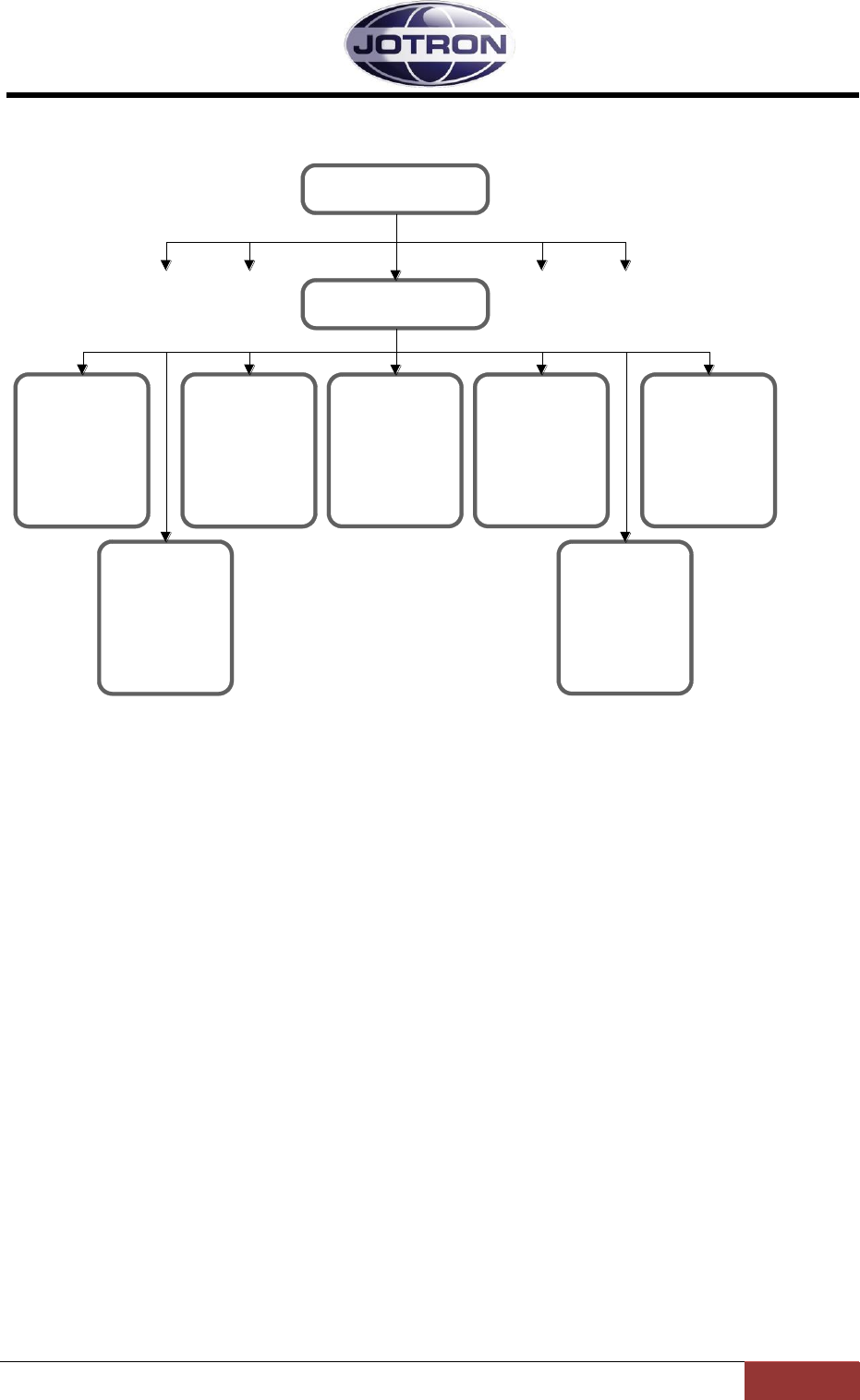
Jotron AS| TR7750C: Operators Manual Operating Instructions
Page 5-6
P/N: 84748 (G)
5.4.3 Interface config group
SysOp access level. Refer to section 5.5.3 for details.
Access control
Set the user
access level for
local operation
LAN
Set parameters for
ethernet (IP)
communication. IP
address, ports to
use, Gateway, etc.
RS232
Set parameters for
RS232 serial
communication.
Bitrate and
protocol
RS485
Set parameters for
RS485 serial
communication.
Bitrate, protocol
and address
Alarm config
Set pullup for the
external alarm pin
and polarity for
select signal
Language
Change the
language for local
control. Availability
varies with model
Interface config
MENU
Rack
Set parameters to
identify location of
the radio:
Rack number,
Row and column
Figure 5.4-3, Interface config group, transmitter
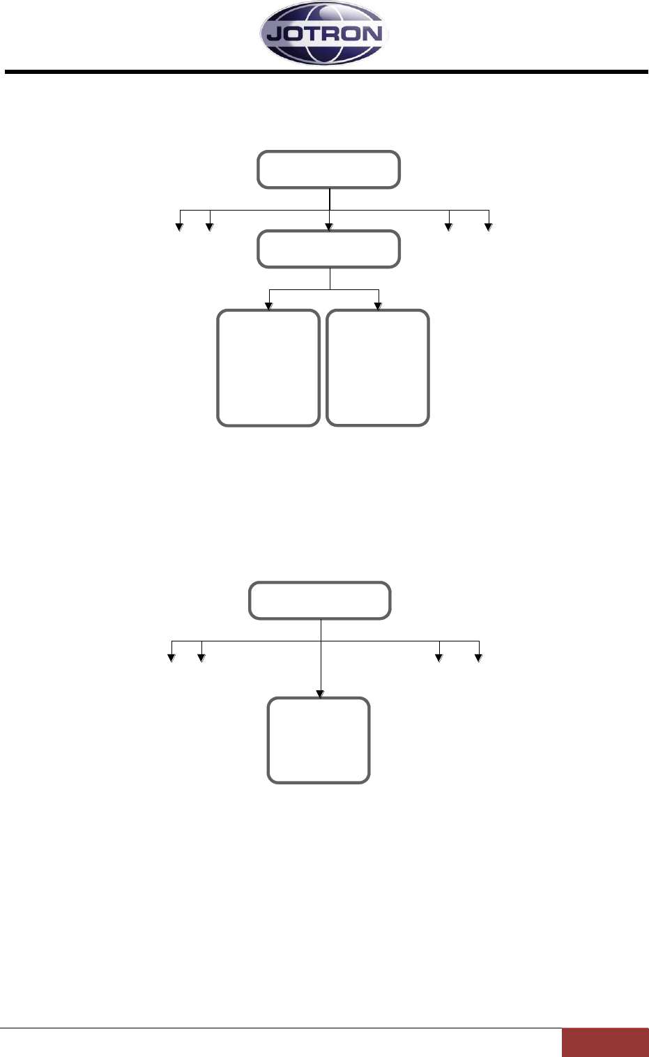
Jotron AS| TR7750C: Operators Manual Operating Instructions
Page 5-7
P/N: 84748 (G)
5.4.4 Bite system group
SysOp and Technician access levels. Refer to section 5.5.4 for details.
Measurements
Measure power
levels, voltages,
currents, lock
detect, etc.
Alarms
Display active
alarms. Identifies
modules and
parameter with
failure.
Bite system
MENU
Figure 5.4-4, Bite system group, transmitter
5.4.5 System info group
All access levels.
System info
ID, FW and HW
release info.
Radio uptime.
MENU
Figure 5.4-5, System info group, transmitter
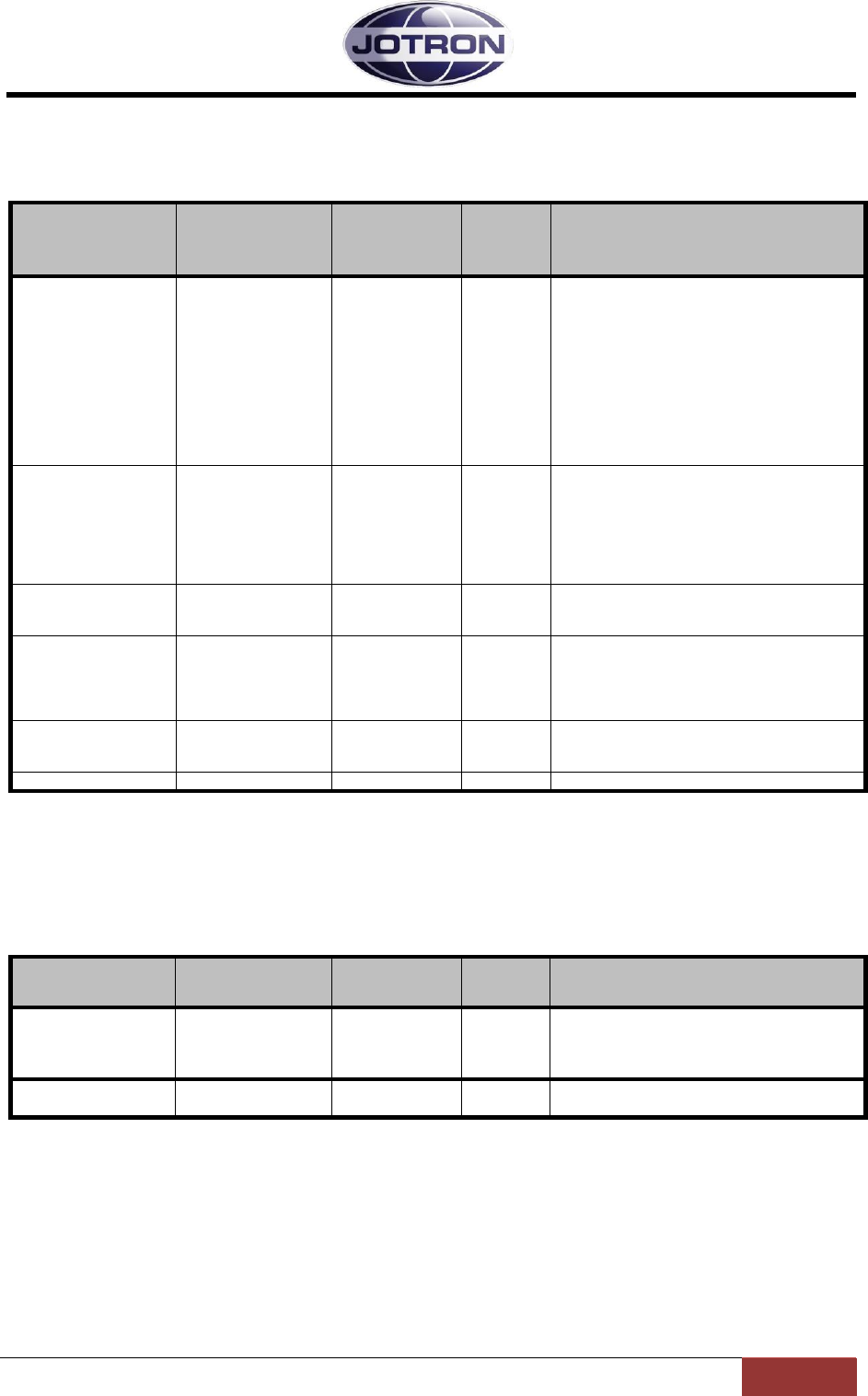
Jotron AS| TR7750C: Operators Manual Operating Instructions
Page 5-8
P/N: 84748 (G)
5.5 Parameter details – transmitter
5.5.1 Radio control group
Menu path:
Radio control
►
Parameter
Range
Default
Details
Operation mode
Main | Norm
Norm
A main radio will enter into standby if an
alarm is detected by the internal BITE
system.
A norm radio will continue operation (if
possible) even if a failure is detected.
In a main / standby configuration, the main
radio is set to Main and the standby radio is
set to Norm. In this way the control can
automatically be transferred to the standby
radio by using the available alarm output and
select input on the radios.
Low power level
30 – 41 dBm
1 dB steps
41 dBm
Set the low power level of the transmitter in 1
dB steps. The low power level is the output
power of the transmitter when the transmitter
is set to low power, either by a command or
by an external input signal.
30 dBm corresponds to 1W output, 41 dBm
is 12W ouput.
Modulation
FM
FM
Select the modulation type / waveform to
use.
Availability depends on radio specifications.
Alarm
On | Off
Off
This setting force the radio into alarm state
(forced alarm) if set to On.
Used for simulations, or to force a radio to
signal an alarm in order to select a backup
(standby) radio.
Standby
On | Off
Off
This setting force the radio into standby state
(forced standby) if set to On.
Used to manually set a radio to standby.
Table 5.5-1, Radio control group, transmitter
5.5.2 TX config group
Menu path:
TX config ►
Parameter
Range
Default
Details
FM
Output power
30 – 47 dBm
1 dB steps
47 dBm
Set the output power for FM operation.
Max. level depends on radio model and is:
47 dBm for TA7650C
FM
Modulation
Up to ±5kHz
deviation
±5kHz
Set the deviation for FM operation.

Jotron AS| TR7750C: Operators Manual Operating Instructions
Page 5-9
P/N: 84748 (G)
Menu path:
TX config ►
Parameter
Range
Default
Details
Audio
Input source
Auto | Line | Mic
| modgen | VoIP
Auto
The input source determines where the audio
is applied to the transmitter.
Auto: Uses line input for when a
key signal is detected on one of
the remote connectors and mic
input if the key signal is detected
on the front panel connector.
Line: Uses the 600 ohm line
interface as the audio source
Mic: Uses the microphone input as
the audio source
Modgen: Uses the internal
modgen as audio input source – se
also Modgen frequency
VoIP: Uses the IP interface as the
audio source (availability depends
on radio specifications).
Audio
Mic sensitivity
-40 – 0 dBm
1 dB steps
-25 dBm
Set the gain (sensitivity) for the microphone
connected to the front panel connector.
Use this setting to increase or decrease the
gain if needed. Setting depends on
microphone used.
Audio
Line sensitivity
-40 – 0 dBm
1 dB steps
-17 dBm
Set the sensitivity of the 600 ohm line input.
This setting determines where the VOGAD
(automatic gain control) start to operate.
Thus if it is set to -17 dBm, levels above -17
dBm will be modulated with 85% (default
setting).
For levels below -17 dBm the modulation will
decrease linearly.
Audio
Line termination
OFF | 600 ohm
600 ohm
Set the termination of the input line to either
OFF or 600 ohm. Normally this is set to 600
ohm, but can be set to OFF on one of the
radios, if two transmitters are connected in
parallel. This is to maintain the 600 ohm
impedance on the lines.
Audio
Line mute level
OFF or
-40 to -10dBm
1 dB steps
OFF
Below this level, the line input will be muted.
Used where noisy lines are connected to the
transmitter to avoid unnecessary noise on
the produced RF signal during periods of
silence (Automatic transmissions; VOLMET,
ATIS)
Audio
Monitor output
Headset |
Monitor output
Monitor
output
Set where the monitor output signal and the
received audio (if a receiver is connected) is
routed.
Can be set to the headset connector, the 600
ohm monitor line output or both.
The monitor signal is the demodulated signal
detected on the output of the transmitter.
Audio
Monitor level
-80 – 10 dBm
-50 dBm
Set the relative output level of the monitor
signal.
Audio
VOGAD
Off, x-fast, fast,
norm, slow, x-
slow
Norm
Set the attack and decrease time of the
automatic gain control (VOGAD).
Off is used only for maintenance
purposes.
Audio
Modgen frequency
100 – 5000 Hz
1 Hz steps
1003 Hz
Set the frequency of the internal modulation
generator. Used in conjunction with the
Audio input source
Audio
Line=>Head gain
-10 to +20 dB
0 dB
Defines the scaling factor of the Rx Audio on
the headset output when the transmitter is
connected to a receiver.
The level is a relative value -10 to +20 dB

Jotron AS| TR7750C: Operators Manual Operating Instructions
Page 5-10
P/N: 84748 (G)
Menu path:
TX config ►
Parameter
Range
Default
Details
Keying
Source
Mic, line, txkey,
txgnd, inband
Mic, txkey
Determines what signal that will be used as
the source for keying the transmitter.
Any combinations can be set
Mic: Local PTT input from a
microphone, where the PTT is
connected to pin 4 and 8(gnd) on
the Mic/headset connector.
Line: Keying from a phantom
signal on the line input. Pin 3 and 6
on the REM connector.
Txkey: The transmitter is keyed by
an external voltage on the
TXKEY_P and TXKEY_N input
pins. Signals located on Pin 7 and
8 on the | connector.
Txgnd: The transmitter is keyed
by a signal on the TXKEY_G input
pin Signals are located on Pin 4
and 8 (gnd) on the REM
connector.
Inband: The transmitter is keyed
using an inband tone (see also
inband frequency and inband
sensitivity)
Keying
Inband frequency
100 – 5000 Hz
1 Hz steps
5000
Set the frequency to be used for the inband
tone that will be used to key the transmitter.
By selected the tone frequency to use, the
transmitter will automatically calculate the
notch filter to use an insert this into the audio
path. Applicable to the line interface input
only.
Keying
Inband trig level
-40 to -10 dBm
-30
The level of the tone used to key the
transmitter on the 600ohm input line.
The value is given in dBm (absolute level
related to 600 ohm). Values above the limit
will key the transmitter.
See also Keying source and Inband
frequency.
Keying
TX Timeout
OFF | 15-300 s
1s steps
OFF
Set the timeout for the key signal. If the PTT
is pressed longer than this timeout, the
transmitter will automatically stop
transmitting. The transmitter will
automatically reset the timer when the key
signal is released.
Keying
RF delay
0 – 200 ms
0 (OFF)
This setting is useful when the transmitter is
used together with external equipment such
as T/R relays, power amplifier or other
equipment that includes RF switchover
relays.
Since the RF switching in the transmitter is
done electronically, the RF is produced in
less than 10ms after the PTT signal is
detected. It could be harmful for the external
relays if the RF is applied to them before
switchover has occurred.
In order to delay the RF carrier this
parameter should be used under such
circumstances. A reasonable setting should
be in the order of 40-50 ms.
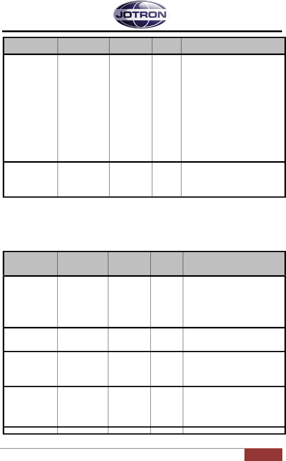
Jotron AS| TR7750C: Operators Manual Operating Instructions
Page 5-11
P/N: 84748 (G)
Menu path:
TX config ►
Parameter
Range
Default
Details
Keying
Loop key bias
Ground, +12V,
Floating
Floating
Connects the centre pin of the line input
transformer to:
Floating: The centre pin is not
connected. If loop keying is used,
an external voltage must be
applied to pin 3 (REM connector)
in order to key the transmitter
Ground: The centre pin is
grounded. If loop keying is used,
an external voltage must be
applied to pin 3 (REM connector)
in order to key the transmitter.
+12V: A 12V DC is supplied on pin
3(REM connector). The transmitter
can be keyed with a relay (or
equivalent) that create a DC path
on the line input pin, pin 3 and 6
(REM connector).
Calibrate
Ref oscillator
-127 – +128
0
This setting is used to fine adjust (calibrate)
the reference oscillator of the transmitter.
The full range is approximately 10 ppm. This
setting should be used with care, and only
when a calibrated frequency measuring
instrument is connected to the transmitter.
Table 5.5-2, TX config group, transmitter
5.5.3 Interface config group
Menu path:
Interface
config ►
Parameter
Range
Default
Details
Access control
SysOp,
Technician,
Operator,
Restricted
SysOp
Set the user access level for local control.
This setting limits the availability of some
menus, depending on the access level. In
order to set the access level from the user
interface, a special hardware key must be
inserted into the microphone/headset
connector. Details of the key is available in
chapter Error! Reference source not
ound.
Set language
Depending on
model
English
Set the language to use on the user
interface. Availability of different languages
depends on specifications when ordering
the transmitter.
Alarm config
Alarm pin pull-up
Disabled |
Enabled
Enabled
The ALARM_OUT_P and ALARM_OUT_N
output pins on AUX1 is used to signal that
the radio has an alarm. This parameter
applies a pull-up voltage to ALARM_OUT_P
when there are no alarms present. When an
alarm is detected the relay contact close.
Alarm config
Select polarity
High to select|
Low to select
Low to
select
The SELECT_IN_P and SELECT_IN_N
input pins on AUX1 can be used to select /
deselect (Standby) the radio with an
external signal (e.g. alarm from a main
radio). This setting determines if the radio
should be operational on a low select input
signal or a high select input signal.
RS485
Bitrate
1200 – 115200
1200
Set the bit rate to use on the RS485 port

Jotron AS| TR7750C: Operators Manual Operating Instructions
Page 5-12
P/N: 84748 (G)
Menu path:
Interface
config ►
Parameter
Range
Default
Details
RS485
Address
1 – 255
1
Set the address to use on the RS485. In a
remote system using the RS485
communication port, all units that are
interconnected need to have a unique
address in order to avoid collisions and
misinterpretation of data.
RS485
Protocol
Legacy |
standard
Legacy
The protocols are described in the data
manual.
Legacy uses a protocol where the 9. bit is
used for address recognition, this is the
protocol used on the previous radio models
(TA7450, RA7202) and is compatible with
the RACS II PC software and the RCU
remote control unit.
Standard is an eight bit protocol that uses
the multidrop capability of the RS485 bus.
For more information on protocols, refer to
the SW manual.
RS232
Bitrate
1200 – 115200
115200
Set the bit rate to use on the RS232
interface ports
LAN
Address
4 octets IP
address
192.168.2.1
IP interface address for the unit. Must be
unique on the network it connects to.
LAN
Netmask
4 octets IP
netmask
255.255.0.0
The netmask used on the IP interface.
Should correspond to the local network that
the radio is connected to.
LAN
Default gateway
4 octets IP
address
0.0.0.0
If set different from the default, the radio unit
will send IP traffic to the default gateway if
the address is unreachable on the local
network
LAN
SNMP port
1 – 65535
161
The input port used for SNMP commands
The default port is the global port for SNMP
commands
LAN
SNMP trap IP
4 octets IP
address
0.0.0.0
The IP address where SNMP traps are sent.
The address can be in the form of a unicast,
multicast or broadcast address.
LAN
SNMP trap port
1 – 65535
162
The output port where SNMP traps are sent.
The default value is the global port for
SNMP traps
LAN
SNMP trap int
0 – 60
5
The interval on which an “alive” trap
(operstate) are sent to the host, if the TrapIP
and TrapPort are set. The value is given in
seconds. 0=OFF
RACK
Number
0 – 100
0
Used to identify the location of the radio
from a remote application. Defines the rack
where the radio is located.
RACK
Row
0 – 20
0
Used to identify the location of the radio
from a remote application. Defines the row
number in the rack. The row number is
counted from the top to the bottom of the
rack.
RACK
Column
0 – 6
0
Used to identify the location of the radio
from a remote application. Defines the
column in the rack. The column number is
counted from the left in steps of one receiver
width or 14TE. There are 84 TE in a 19”
rack.
I.e. in a 19” frame width 6 receivers, the
receivers will have the column set to
1,2,3,4,5 or 6.
In a 19” frame width 3 transmitters, the
transmitters will have the column set to 1,3
or 5.
Table 5.5-3, Interface config group, transmitter

Jotron AS| TR7750C: Operators Manual Operating Instructions
Page 5-13
P/N: 84748 (G)
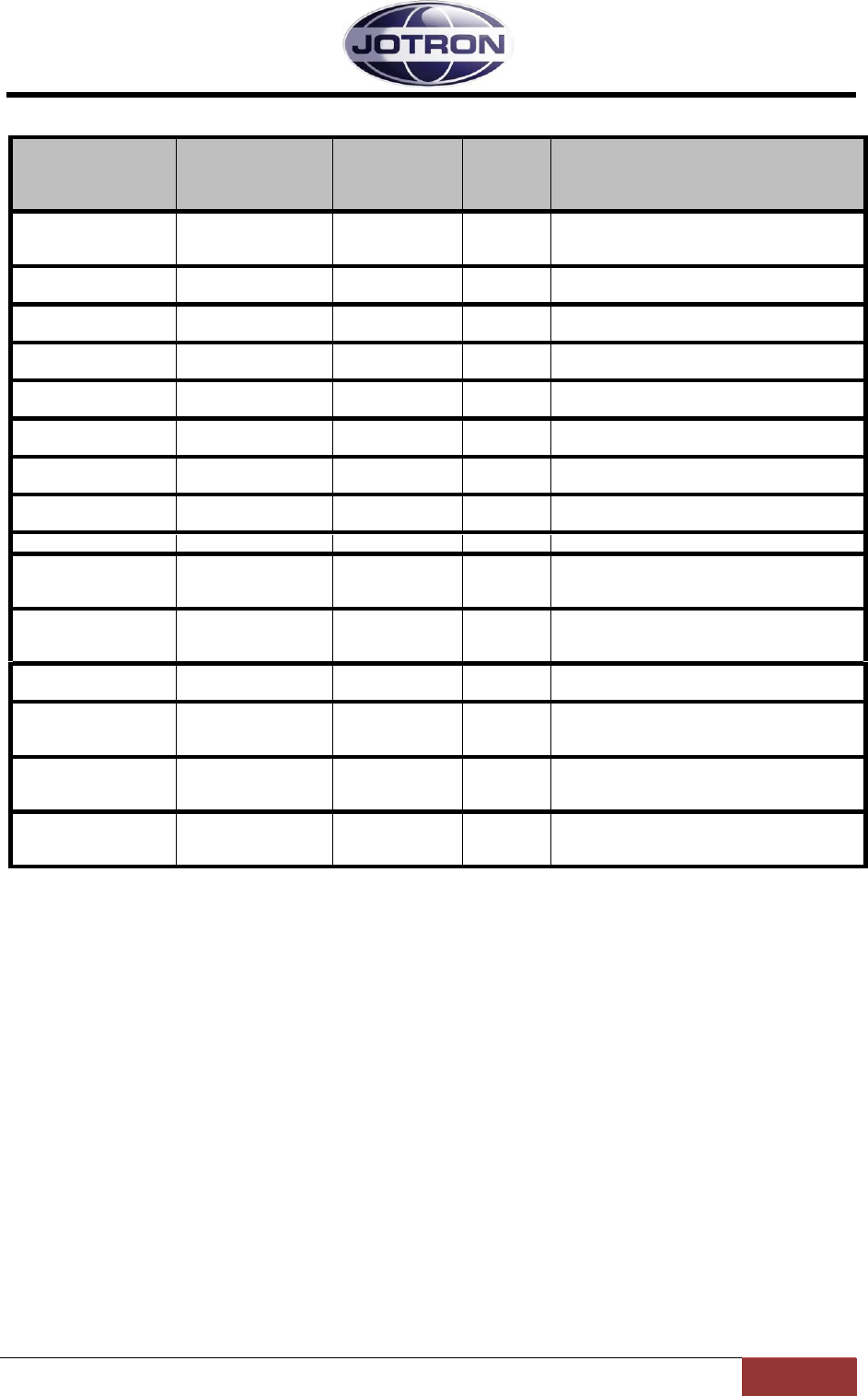
Jotron AS| TR7750C: Operators Manual Operating Instructions
Page 5-14
P/N: 84748 (G)
5.5.4 Bite system group
Menu path:
Interface
config ►
Parameter
Range
Default
Details
TX alarm
Depends on the
alarm status of the
radio unit
This option displays all active alarms in the
unit.
See section 6.1 for more info.
Measurements
Forward
30 – 47 dBm
Displays the forward power in dBm detected
at the output of the transmitter
Measurements
Reflected
0 – Forward
power
Displays the reflected power in dBm
detected on the output of the transmitter
Measurements
VSWR
1 : ∞
Displays the calculated VSWR from the
forward and reflected measurements
Measurements
Modulation
Up to ± 5kHz
Displays the measured modulation level on
the output of the transmitter [kHz]
Measurements
Current
Max 10 A when
keyed
Displays the total current consumption (28V)
of the transmitter [A]
Measurements
PA Temp
Max 85°C
Displays the temperature measured on the
PA module in the transmitter [°C]
Measurements
LO level
Min. 0 dBm
Displays the level measured at the output of
the local oscillator in dBm
Measurements
Line level
Input line level
Displays the input line level in dBm
Measurements
28 Volt
20.0 – 29.0 V
Displays the regulated 28V supply from the
power regulator board.
The 28V is used on the PA board.
Measurements
12 Volt
11.0 – 12.8 V
Displays the regulated 12V supply from the
power regulator board
The 12V is used on the main board
Measurements
6 Volt
5.0 – 7.0 V
Displays the regulated 6V on the modulator
board
Measurements
5 Volt
4.5 – 5.5 V
Displays the regulated 5V supply from the
power regulator board.
The 5V is used on several modules
Measurements
-5 Volt
-6.2 - -4.0 V
Displays the regulated -5V supply from the
power regulator board.
The -5V is used on the main board.
Measurements
3.3 Volt
2.9 – 3.6 V
Displays the regulated 3.3V supply from the
power regulator board.
The 3.3V is used on several modules
Table 5.5-4, Bite system group, transmitter
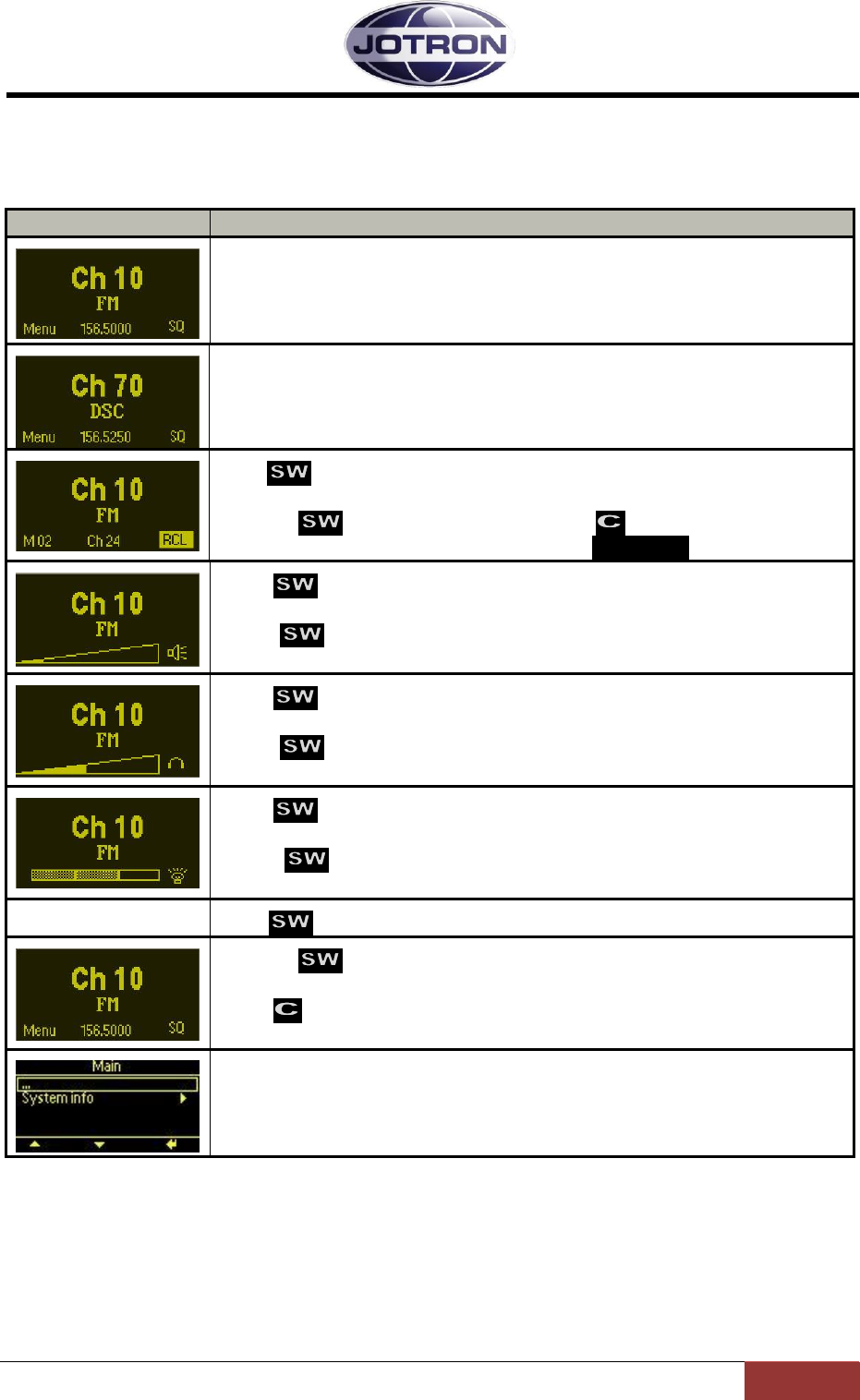
Jotron AS| TR7750C: Operators Manual Operating Instructions
Page 5-15
P/N: 84748 (G)
5.6 User menu – receiver (Restricted access level)
Main display window in restricted mode.
Display
Description
When the receiver is switched on, it will show the channel, the frequency
and the operation mode (FM).
When the DSC dedicated receiver is switched on, it will show the DSC
channel, the DSC frequency and the operation mode (DSC).
Press to navigate to the channel recall screen.
Select any channel (up to 100) that is previously stored in the radio by
rotating . Recall selected channel with
If no channel is stored, the display will show: CH: No channels
Press to navigate to the loudspeaker audio output screen.
This setting adjusts the audio level output in the integrated loudspeaker.
Rotate CW or CCW to adjust the audio level.
Press to navigate to the headset audio output screen.
This setting adjusts the audio level output in the integrated loudspeaker.
Rotate CW or CCW to adjust the audio level.
Press to navigate to the display intensity adjust screen.
This setting adjusts the intensity of the display and LED indicators.
Rotate CW or CCW to adjust the intensity.
Press to return to the default screen
Pressing from the main display will bring up the menu options that
are available for the current user level.
Press to disable / active the squelch.
Menus for user level: Restricted
For details regarding submenus, refer to chapter 5.4.
Table 5.6-1, User menu selections receiver - restriced access level
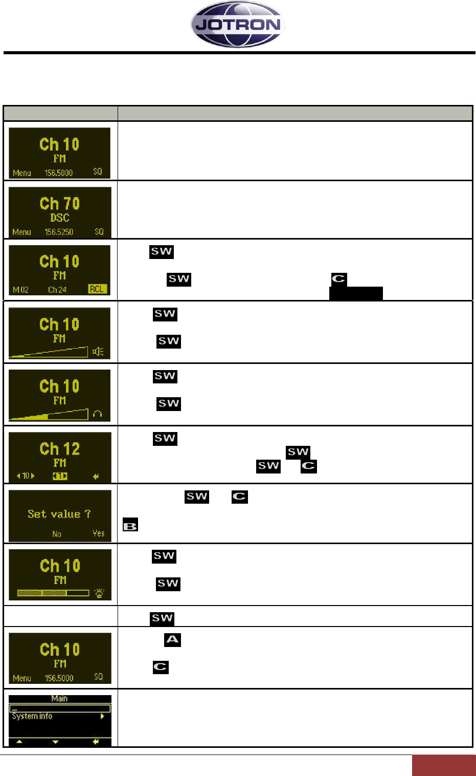
Jotron AS| TR7750C: Operators Manual Operating Instructions
Page 5-16
P/N: 84748 (G)
5.7 User menu – receiver (Default access level)
Main display window for user levels: Operator, Technician and SysOp.
Display
Description
When the receiver is switched on, it will show the channel, the frequency
and the operation mode (FM).
When the DRC dedicated receiver is switched on, it will show the DSC
channel, the DSC frequency and the operation mode (DRC).
Press to navigate to the channel recall screen.
Select any channel (up to 100) that is previously stored in the radio by
rotating . Recall selected channel with
If no channel is stored, the display will show: CH: No channels
Press to navigate to the loudspeaker audio output screen.
This setting adjusts the audio level output in the integrated loudspeaker.
Rotate CW or CCW to adjust the audio level.
Press to navigate to the headset audio output screen.
This setting adjusts the audio level output in the integrated loudspeaker.
Rotate CW or CCW to adjust the audio level.
Press to navigate to the channel select screen.
Select channel number by rotating CW or CCW.
Confirm new frequency with or .
Confirm with or .
If the channel is already programmed, the channel may be cleared using
Press to navigate to the display intensity adjust screen.
This setting adjusts the intensity of the display and LED indicators.
Rotate CW or CCW to adjust the intensity.
Press to return to the default screen
Pressing from the main display will bring up the menu options
available for the current user level.
Press to disable / activate the squelch.
Menus for user level: Operator
For details regarding submenus, refer to chapter 5.4.
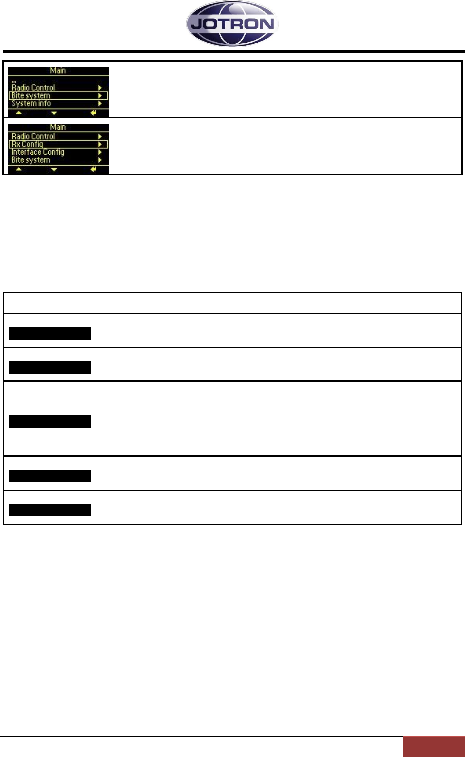
Jotron AS| TR7750C: Operators Manual Operating Instructions
Page 5-17
P/N: 84748 (G)
Menus for user level: Technician
For details regarding submenus, refer to chapter 5.4.
Menus for user level: SysOp
For details regarding submenus, refer to chapter 5.4.
Table 5.7-1, User menu selections receiver - Operator, Technician and SysOp access levels
5.8 Setting, information and configuration menus – receiver
Under the menu selection from the user menu, various submenu groups are available depending on
the user level.
The submenus and details for them are shown in the tables below.
Submenu
Access level
Description
Radio control ►
SysOp, Technician
Access to operation mode, low power level, climax offset
parameters, modulation and standby settings.
RX config ►
SysOp
Access to configuration parameters for modulation, audio
settings, Squelch settings and internal calibration settings.
Interface config ►
SysOp
Access to configuration parameters for the ethernet
interface, RS232 port, RS485 port, various pin settings on
the hardware interface (remote connectors) and the user
access level.
Bite system ►
SysOp, Technician
Displays information about active alarms and gives the
user access to internal measurements.
System info ►
All
Displays information about the firmware and hardware
release, system up-time and radio identification
Table 5.8-1, Submenus available on the receiver
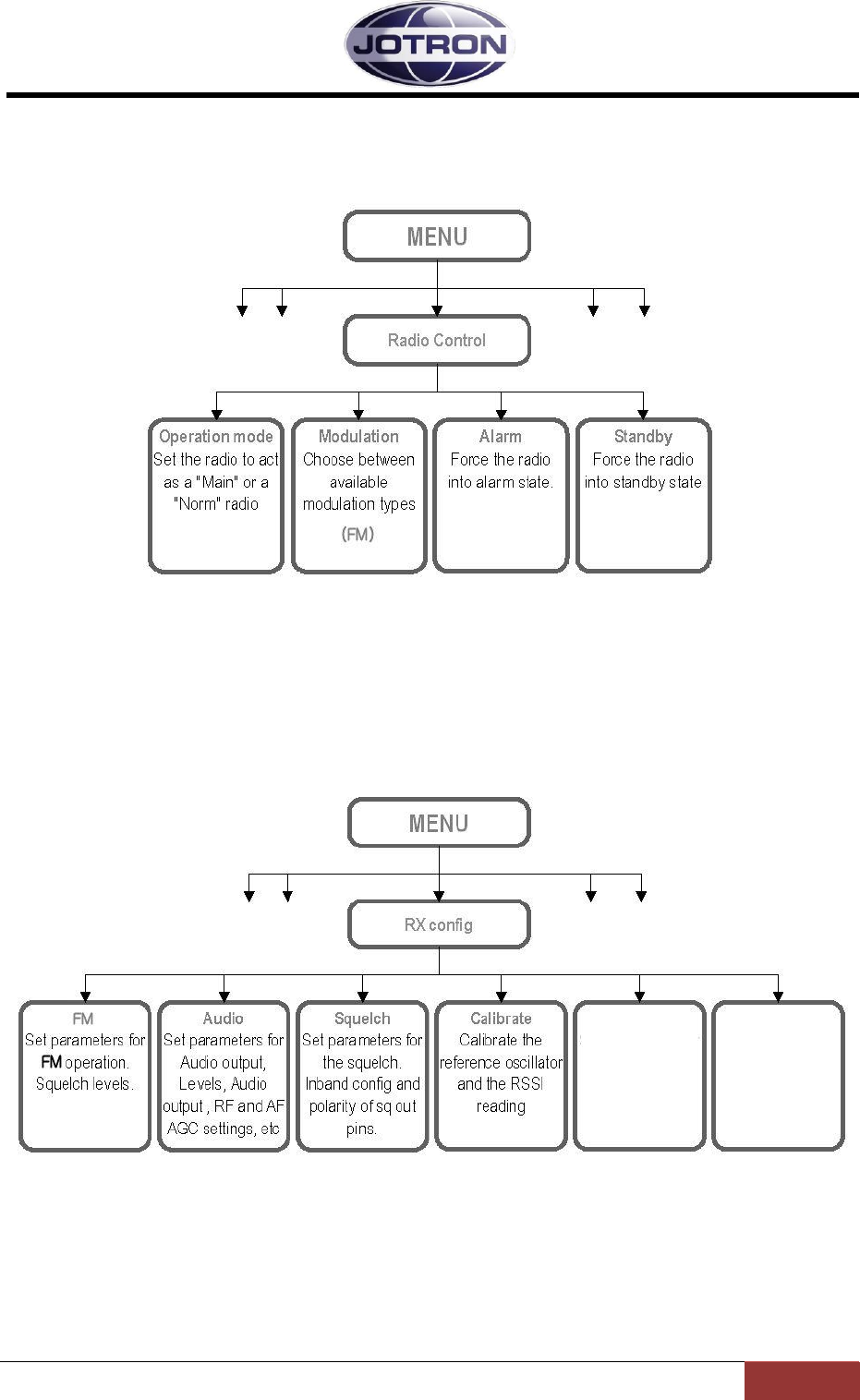
Jotron AS| TR7750C: Operators Manual Operating Instructions
Page 5-18
P/N: 84748 (G)
5.8.1 Radio control group
SysOp and Technician access levels. Refer to section 5.9.1 for details.
Figure 5.8-1, Radio control group, receiver
5.8.2 RX config group
SysOp access level. Refer to section 5.9.2 for details.
Figure 5.8-2, RX config group, receiver
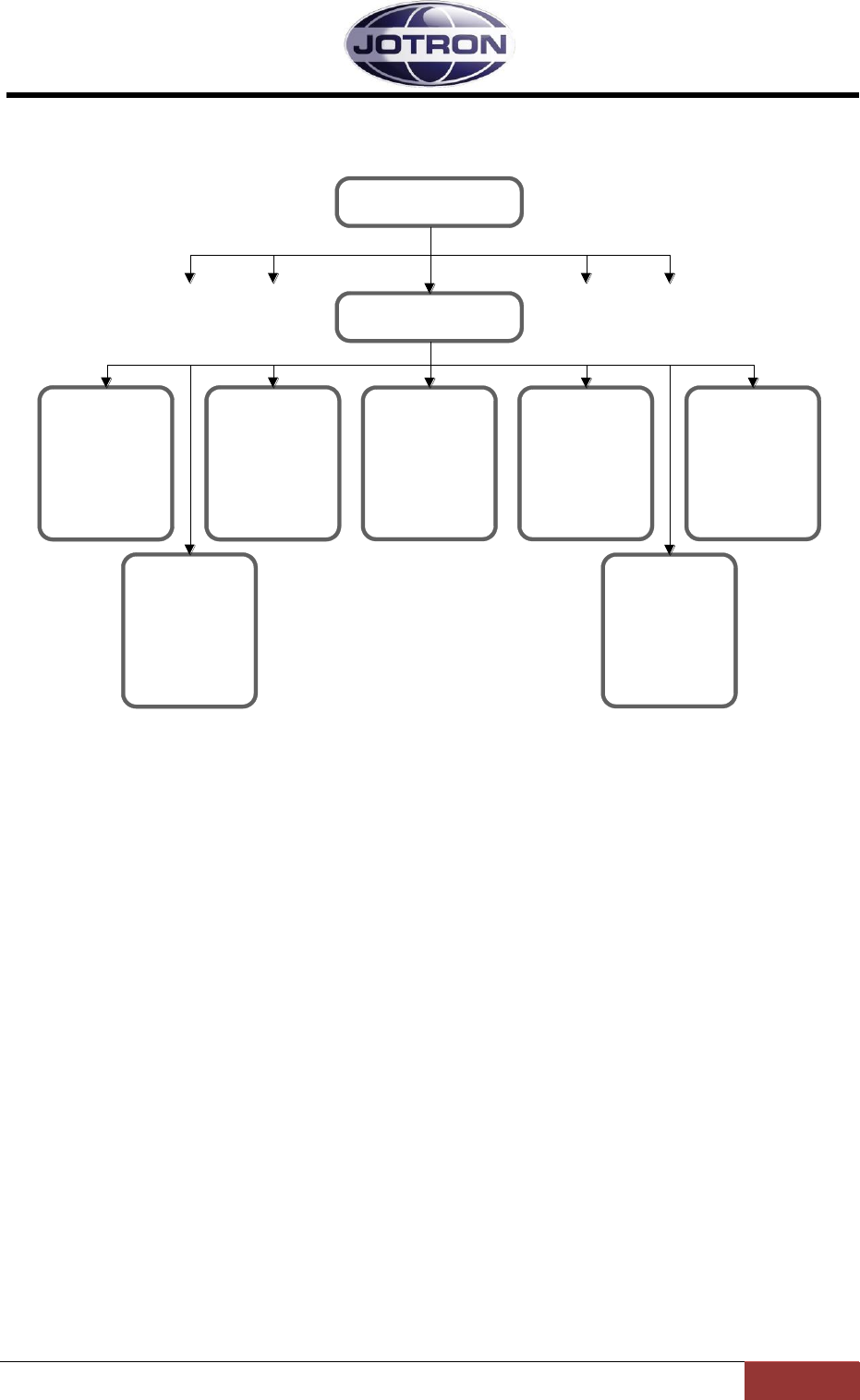
Jotron AS| TR7750C: Operators Manual Operating Instructions
Page 5-19
P/N: 84748 (G)
5.8.3 Interface config group
SysOp access level. Refer to section 5.9.3 for details.
Access control
Set the user
access level for
local operation
Rack
Set parameters to
identify location of
the radio:
Rack number, row
and column
RS232
Set parameters for
RS232 serial
communication.
Bitrate and
protocol
RS485
Set parameters for
RS485 serial
communication.
Bitrate, protocol
and address
Alarm config
Set pullup for the
external alarm pin
and polarity for
select signal
Language
Change the
language for local
control. Availability
varies with model
Interface config
MENU
LAN
Set parameters for
ethernet (IP)
communication. IP
address, ports to
use, Gateway, etc.
Figure 5.8-3, Interface config group, receiver

Jotron AS| TR7750C: Operators Manual Operating Instructions
Page 5-20
P/N: 84748 (G)
5.8.4 Bite system group
SysOp and Technician access levels. Refer to section 5.9.4 for details.
Measurements
Measure power
levels, voltages,
currents, lock
detect, etc.
Alarms
Display active
alarms. Identifies
modules and
parameter with
failure.
Bite system
MENU
Figure 5.8-4, Bite system group, receiver
5.8.5 System info group
Available for all access levels
System info
ID, FW and HW
release info.
System uptime.
MENU
Figure 5.8-5, System info group, receiver

Jotron AS| TR7750C: Operators Manual Operating Instructions
Page 5-21
P/N: 84748 (G)
5.9 Parameter details – receiver
5.9.1 Radio control group
Menu path:
Radio control
►
Parameter
Range
Default
Details
Squelch level
-10 dBuV to +30
dBuV
0 dBuV
Squelch level
This squelch level is the level for the digital
noise compensated squelch.
Operation mode
Main | Norm
Norm
A main radio will enter into standby if an
alarm is detected by the internal BITE
system.
A norm radio will continue operation (if
possible) even if a failure is detected.
In a main / standby configuration, the main
radio is set to Main and the standby radio is
set to Norm. In this way the control can
automatically be transferred to the standby
radio by using the available alarm output and
select input on the radios.
Modulation
FM
FM
Select the modulation type / waveform to
use.
Availability depends on radio specifications.
Alarm
On | Off
Off
This setting force the radio into alarm state
(forced alarm) if set to On.
Used for simulations, or to force a radio to
signal an alarm in order to select a backup
(standby) radio.
Standby
On | Off
Off
This setting force the radio into standby state
(forced standby) if set to On.
Used to manually set a radio to standby.
Table 5.9-1, Radio control group, receiver

Jotron AS| TR7750C: Operators Manual Operating Instructions
Page 5-22
P/N: 84748 (G)
5.9.2 RX config group
Menu path:
RX config ►
Parameter
Range
Default
Details
Audio
Output source
Speaker |
Headphone |
Lineout |
VoIP
Speaker,
Headphone,
Lineout
The output source determines where the
received audio is output.
Line: Output audio on the 600
ohm line interface
Speaker: Output audio on the
integrated speaker.
Headphone: Output audio to a
headphone connected to the front
panel connector.
VoIP: Output audio on the IP
interface (availability depends on
radio specifications).
Audio
Line output level
-40 – +10 dBm
1 dB steps
-10 dBm
The max. output level on the 600 ohm line
output.
Audio
RF AGC
Off, x-fast, fast,
norm, slow, x-
slow
Norm
Set the attack and release times for the RF
AGC
Off is used only for maintenance
purposes.
Audio
AF AGC
On | Off
Off
Set the automatic AF gain control on or off.
Setting AF AGC on will lead to constant
audio output when received signals have
varying modulation levels
Audio
Mute on transmit
On | Off
On
Set this to On if the receiver should be
muted while transmitting. Requires that the
Tx busy signal on the RX connector on the
transmitter is routed to the TX busy input on
the receiver REM connector.
Squelch
Override level
-10 dBuV to +30
dBuV
20 dBuV
The override level where the analogue
squelch will open even if it is a “noisy”
signal. This squelch level overrides the
noise compensated squelch. Setting this
level to a lower level than the “SQ level” will
disable the noise compensated squelch
completely.
Squelch
Inband config
Off, open,
closed, both
Off
Defines the behavior of the inband squelch
signal.
Off: No inband tone is generated
Open: An inband tone is
generated when the squelch is
open (receiving)
Closed: An inband tone is
generated when the squelch is
closed (muted)
Both: Different tones are
generated depending on the
status of the squelch.
Squelch
Inband freq open
100 – 5000 Hz
1 Hz steps
5000
Set the frequency to be used for the inband
tone that will be used to signal that the
squelch is open. Requires that open is
included in the Inband config setting. The
receiver will automatically notch the received
signal and insert a tone at the given
frequency.
Applicable to the line interface output only.
Squelch
Inband freq closed
100 – 5000 Hz
1 Hz steps
5000
Set the frequency to be used for the inband
tone that will be used to signal that the
squelch is closed. Requires that closed is
included in the Inband config setting. The
receiver will automatically insert a tone at
the given frequency.
Applicable to the line interface output only.
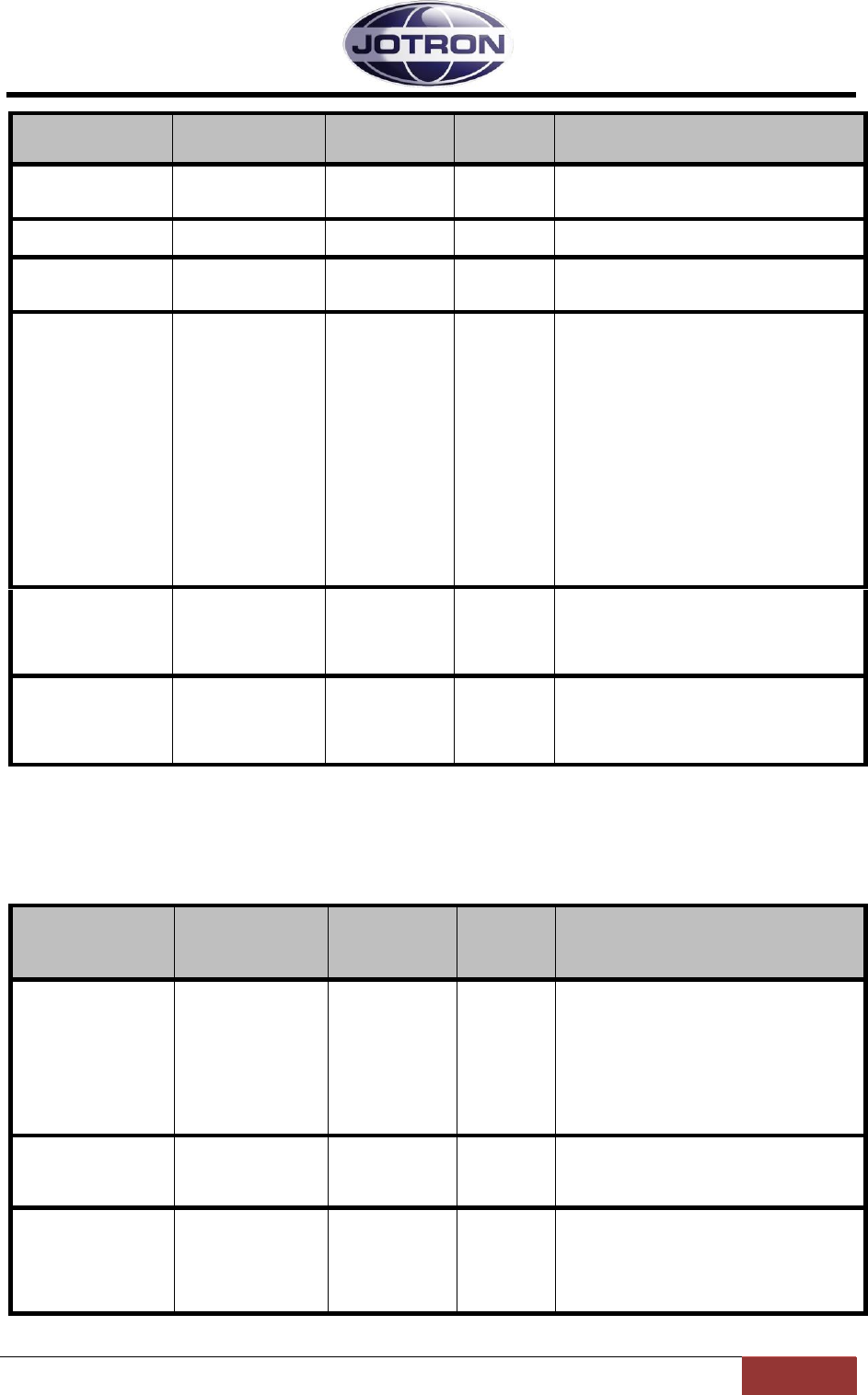
Jotron AS| TR7750C: Operators Manual Operating Instructions
Page 5-23
P/N: 84748 (G)
Menu path:
RX config ►
Parameter
Range
Default
Details
Squelch
Inband level
-30 to -10
-24
The level of the inband tone relative to the
setting in the line level output level in dB,
Applicable to the line interface output only.
Squelch
SqOut output
Set the behavior of the SqOut output (AUX2,
p.1 and p.2).
Squelch
RxBusy output
Closed | Open |
Closed on busy|
Open on busy
Closed on
busy
Set the behavior of the RxBusy output
(REM, p.5).
Calibrate
Ref oscillator
-127 – +128
0
This setting is used to fine adjust (calibrate)
the reference oscillator of the receiver. The
full range is approximately 10 ppm. This
setting should be used with care, and only
when a calibrated frequency measuring
instrument is used to measure the frequency
of the receiver.
The exact frequency of the receiver can be
determined either by connecting a spectrum
analyzer to the antenna connector of the
receiver and measure the leakage of the LO
output (45 MHz above the operating
frequency) – or by using a radio test set to
measure the bandwidth of the receiver and
adjust until centre is on the operating
frequency.
Calibrate
RSSI reading
-10 to +10 dB
0 dB
In order to measure the RSSI level exactly,
there is a provision to calibrate the reading.
Normally the reading is within +/-2 dB
without calibration, but it can be useful if to
signals are being compared.
Factory preset
0, 1
0
Writing a “1” to this parameter will reset the
receiver and restore the settings that where
set before shipping from the factory. Use
with care – all settings that has been
changed will be reset!
Table 5.9-2, RX config group, receiver
5.9.3 Interface config group
Menu path:
Interface
config ►
Parameter
Range
Default
Details
Access control
SysOp,
Technician,
Operator,
Restricted
SysOp
Set the user access level for local control.
This setting limits the availability of some
menus, depending on the access level. In
order to set the access level from the user
interface, a special hardware key must be
inserted into the microphone/headset
connector. Details of the key is available in
chapter Error! Reference source not
ound..
Set language
Depending on
model
English
Set the language to use on the user
interface. Availability of different languages
depends on specifications when ordering
the receiver.
Alarm config
Alarm pin pullup
Disabled |
Enabled
Enabled
The ALARM_OUT_P and ALARM_OUT_N
output pins on AUX1 is used to signal that
the radio has an alarm. This parameter
applies a pullup voltage to ALARM_OUT_P
when there are no alarms present. When an
alarm is detected the relay contact close.

Jotron AS| TR7750C: Operators Manual Operating Instructions
Page 5-24
P/N: 84748 (G)
Menu path:
Interface
config ►
Parameter
Range
Default
Details
Alarm config
Select polarity
High to select|
Low to select
Low
The SELECT_IN_P and SELECT_IN_N
input pins on AUX1 can be used to select /
deselect (Standby) the radio with an
external signal (e.g. alarm from a main
radio). This setting determines if the radio
should be operational on a low select input
signal or a high select input signal.
RS485
Bitrate
1200 – 115200
1200
Set the bit rate to use on the RS485 port
RS485
Address
1 – 255
1
Set the address to use on the RS485. In a
remote system using the RS485
communication port, all units that are
interconnected need to have a unique
address in order to avoid collisions and
misinterpretation of data.
RS485
Protocol
Legacy |
standard
Legacy
The protocols are described in the data
manual.
Legacy uses a protocol where the 9. bit is
used for address recognition, this is the
protocol used on the previous radio models
(TA7450, RA7202) and is compatible with
the RACS II PC software and the RCU
remote control unit.
Standard is an eight bit protocol that uses
the multidrop capability of the RS485 bus.
For more information on protocols, refer to
the SW manual.
RS232
Bitrate
1200 – 115200
115200
Set the bit rate to use on the RS232
interface ports
LAN
Address
4 octets IP
address
192.168.2.1
IP interface address for the unit. Must be
unique on the network it connects to.
LAN
Netmask
4 octets IP
netmask
255.255.0.0
The netmask used on the IP interface.
Should correspond to the local network that
the radio is connected to.
LAN
Default gateway
4 octets IP
address
0.0.0.0
If set different from the default, the radio unit
will send IP traffic to the default gateway if
the address is unreachable on the local
network
LAN
SNMP port
1 – 65535
161
The input port used for SNMP commands
The default port is the global port for SNMP
commands
LAN
SNMP trap IP
4 octets IP
address
0.0.0.0
The IP address where SNMP traps are sent.
The address can be in the form of a unicast,
multicast or broadcast address.
LAN
SNMP trap port
1 – 65535
162
The output port where SNMP traps are sent.
The default value is the global port for
SNMP traps
LAN
SNMP trap interval
0 – 60
5
The interval on which an “alive” trap
(operstate) are sent to the host, if the TrapIP
and TrapPort are set. The value is given in
seconds. 0=OFF
LAN
VDL output IP
4 octets IP
address
0.0.0.0
The IP address that VDL packets received
will be sent to. Must be set in order to detect
VDLpackets.
LAN
VDL output port
1 – 65535
3006
The output port used for VDL traffic if the
VDL input source is set to IP
Rack
Number
0 – 100
0
Used to identify the location of the radio
from a remote application. Defines the rack
where the radio is located.
Rack
Row
0 – 20
0
Used to identify the location of the radio
from a remote application. Defines the row
number in the rack. The row number is
counted from the top to the bottom of the
rack.

Jotron AS| TR7750C: Operators Manual Operating Instructions
Page 5-25
P/N: 84748 (G)
Menu path:
Interface
config ►
Parameter
Range
Default
Details
Rack
Column
0 – 6
0
Used to identify the location of the radio
from a remote application. Defines the
column in the rack. The column number is
counted from the left in steps of one receiver
width or 14TE. There are 84 TE in a 19”
rack.
I.e. in a 19” frame width 6 receivers, the
receivers will have the column set to
1,2,3,4,5 or 6.
In a 19” frame width 3 transmitters, the
transmitters will have the column set to 1,3
or 5.
Table 5.9-3, Interface config group, receiver
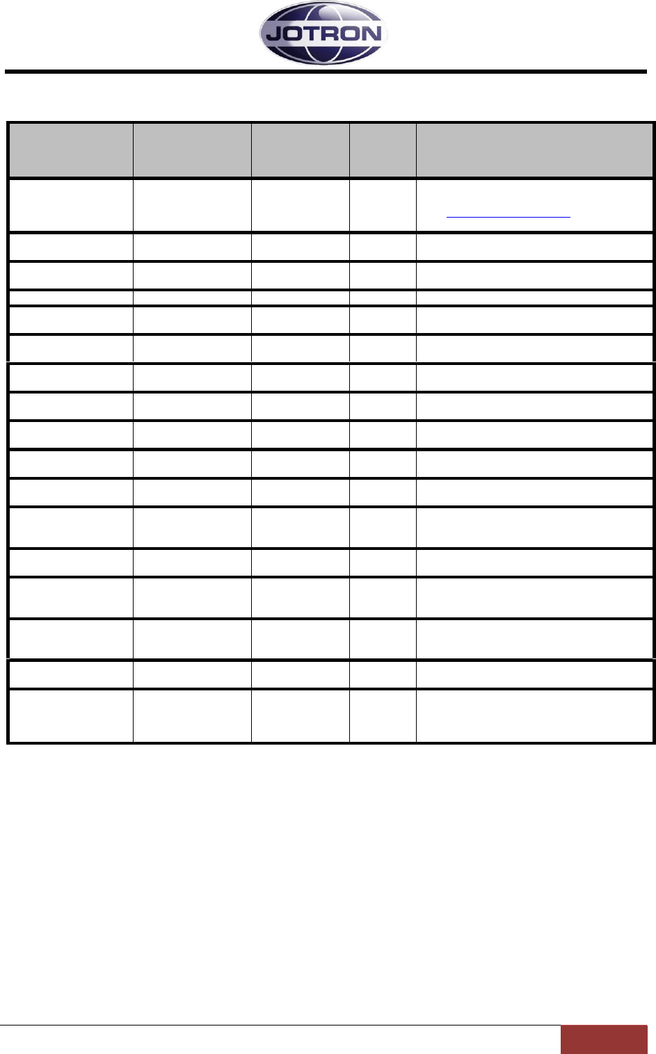
Jotron AS| TR7750C: Operators Manual Operating Instructions
Page 5-26
P/N: 84748 (G)
5.9.4 Bite system group
Menu path:
Interface
config ►
Parameter
Range
Default
Details
RX alarm
Depends on the
alarm status of the
radio unit
This menu item displays all active alarms in
the unit.
See Receiver error conditions for more
information
Measurements
RSSI
-10 - +110 dBuV
Displays the received signal level (RSSI) in
dbuV
Measurements
Line level
-40 - +10 dBm
Displays the level measured on the output of
the 600 ohm line interface
Measurements
AGC volt
0 – 5 V
Displays the internal AGC voltage
Measurements
Codec/Eth LD
Lock / Unlock
Displays the status of the VCO used for the
Codec and Ethernet chips.
Measurements
Temperature
Max 85°C
Displays the internal temperature measured
on the main board [°C]
Measurements
DC current
0.1 – 0.3 A
Displays the total current consumption [28V]
of the receiver [A]
Measurements
IF current
20 – 60 mA
Displays the current consumption in the IF
(Intermediate Frequency) circuit [mA]
Measurements
LNA current
20 – 60 mA
Displays the current consumption in the LNA
(Low noise amplifier) [mA]
Measurements
LO level
Min. 15 dBm
Displays the level measured at the output of
the local oscillator in dBm
Measurements
LO lock
Lock / Unlock
Displays the status of the local oscillator in
the receiver.
Measurements
12 Volt
11.0 – 12.8V
Displays the regulated 12V supply from the
power supply board
The 12V is used on the main board
Measurements
6 Volt
5.0 – 7.0V
Displays the regulated 6V on the
demodulator board
Measurements
5 Volt
4.5 – 5.5V
Displays the regulated 5V supply from the
power supply board.
The 5V is used on several modules
Measurements
3.3 Volt
2.9 – 3.6V
Displays the regulated 3.3V supply from the
power supply board.
The 3.3V is used on several modules
Measurements
AC
Present/Not
Present / Not present. Signals that AC is
present or not present at the input of the unit.
Measurements
VDL2-CO
0 – 100 %
Displays the channel occupancy (CO) when
in VDL 2 mode. The value is calculated
every second, or by the interval set in VDL2-
CO Trap interval.
Table 5.9-4, Bite system group, receiver
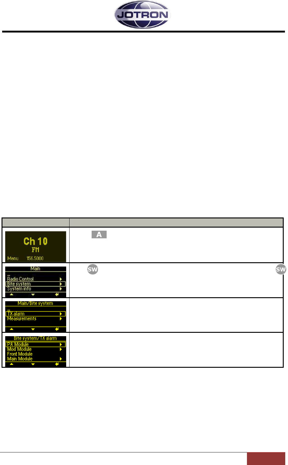
Jotron AS| TR7750C: Operators Manual ERROR CONDITIONS AND CORRECTIVE ACTIONS
Page 6-1
P/N: 84748 (pre_F)
6 ERROR CONDITIONS AND CORRECTIVE ACTIONS
When the internal BITE (Built In Test Equipment) in the transmitter or the receiver units detects a
failure, the alarm indicator on the front panel of the unit will be lit. In addition the radio unit will
signal with an automatically generated SNMP trap message on the ethernet interface.
Details about the fault that caused the alarm are accessible for user access levels: SysOp and
Technician.
The error messages are available in two levels, first the module that has the failure will be identified,
next the user has the option to view in details what particular message that caused the alarm
condition.
In the following (LRU) refers to the Lowest Replaceable Unit – and is normally the first line
maintenance where the complete unit is replaced. (LRM) refers to the Lowest Replaceable Module
and is the module within the unit that can be replaced. The LRM level normally requires a well
equipped workshop with appropriate tools for testing and calibration.
6.1 Transmitter error conditions
Display
Description
Press from the main display to bring up the available menus.
Use to navigate to the Bite system menu and select by pressing
Select TX alarm
The displays shows module(s) where the BITE system has detected failures.
To view more details about the failure, select module.
Table 6.1-1, Alarm indication, transmitter navigation

Jotron AS| TR7750C: Operators Manual ERROR CONDITIONS AND CORRECTIVE ACTIONS
Page 6-2
P/N: 84748 (pre_F)
28V
12V
5V
3.3V
-5V
One of the voltage
readings is out of
range
High
Temperature
Temperature
reading is above
+85°C
High Current
Current
consumption is
above 10A
High SWR
Caused by a SWR
reading higher
than 1:3
PA Module
TX alarm
Action:
Check antenna /
Antenna
connectors /
Antenna Cable
Action:
Replace -
TX unit (LRU)
PA module (LRM)
Probable cause:
Defective output
transistor
Action:
Replace -
TX unit (LRU)
PA module (LRM)
Probable cause:
Defective fan(s)
Action:
Replace -
TX unit (LRU)
PA module (LRM)
Probable cause:
Defective
component on
power regulator
board
Figure 6.1-1, Transmitter PA module, errors and corrective actions
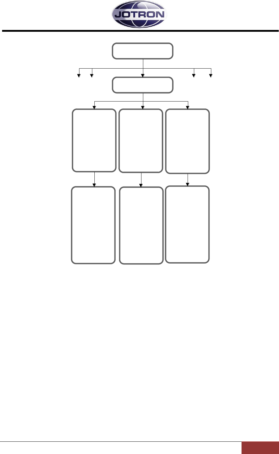
Jotron AS| TR7750C: Operators Manual ERROR CONDITIONS AND CORRECTIVE ACTIONS
Page 6-3
P/N: 84748 (pre_F)
6V
Failure on 6V
regualtor on mod
module
LO lock detect
Synthesizer is out
of lock
LO level
The LO level is
below 0dBm
Mod module
TX alarm
Action:
Replace -
TX unit (LRU)
Modulator module
(LRM)
Probable cause:
Defective
synthesizer circuits
/ VCO / TCXO
Action:
Replace -
TX unit (LRU)
Modulator module
(LRM)
Probable cause:
Defective
synthesizer circuits
/ VCO / TCXO
Action:
Replace -
TX unit (LRU)
Modulator module
(LRM)
Probable cause:
Defective 6V
regulator
modulator board
Figure 6.1-2, Transmitter Modulator module, errors and corrective actions
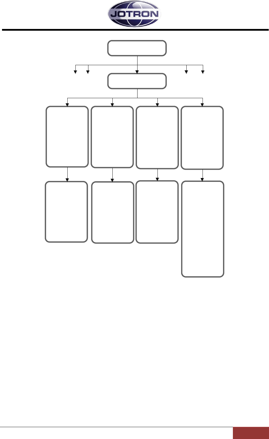
Jotron AS| TR7750C: Operators Manual ERROR CONDITIONS AND CORRECTIVE ACTIONS
Page 6-4
P/N: 84748 (pre_F)
Front
Failure on the
communication
link to the front
panel
DSP
Failure on the DSP
chip on the main
board
Codec
SPI
RemExp
BiteADC
Failure on one or
more ICs on the
main board
Ethernet
Failure on the
ethernet controller
on the main board
Main Module
TX alarm
Action:
Replace-
TX unit (LRU)
Main module
(LRM)
Probable cause:
Failure on the
ethernet chip
Action:
Replace -
TX unit (LRU)
Main module
(LRM)
Probable cause:
Failure on the
specified chip
Action:
Replace -
TX unit (LRU)
Main module
(LRM)
Probable cause:
Failure on the DSP
chip.
Action:
Replace -
TX unit (LRU)
Check connections
to the front panel,
replace front panel
(LRM)
Probable cause:
Failure on the front
panel or
connectors betw.
front panel and
main board
Figure 6.1-3, Transmitter Main module, errors and corrective actions
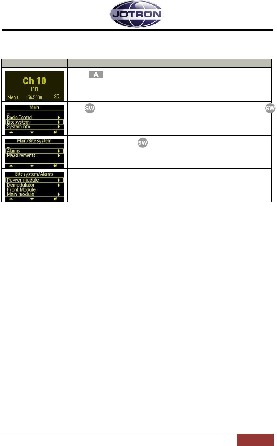
Jotron AS| TR7750C: Operators Manual ERROR CONDITIONS AND CORRECTIVE ACTIONS
Page 6-5
P/N: 84748 (pre_F)
6.2 Receiver error conditions
Display
Description
Press from the main display to bring up the available menus.
Use to navigate to the Bite system menu and select by pressing
Select Alarms and press
The displays shows module(s) where the BITE system has detected failures.
To view more details about the failure, select module.
Table 6.2-1, Alarm indication, receiver navigation
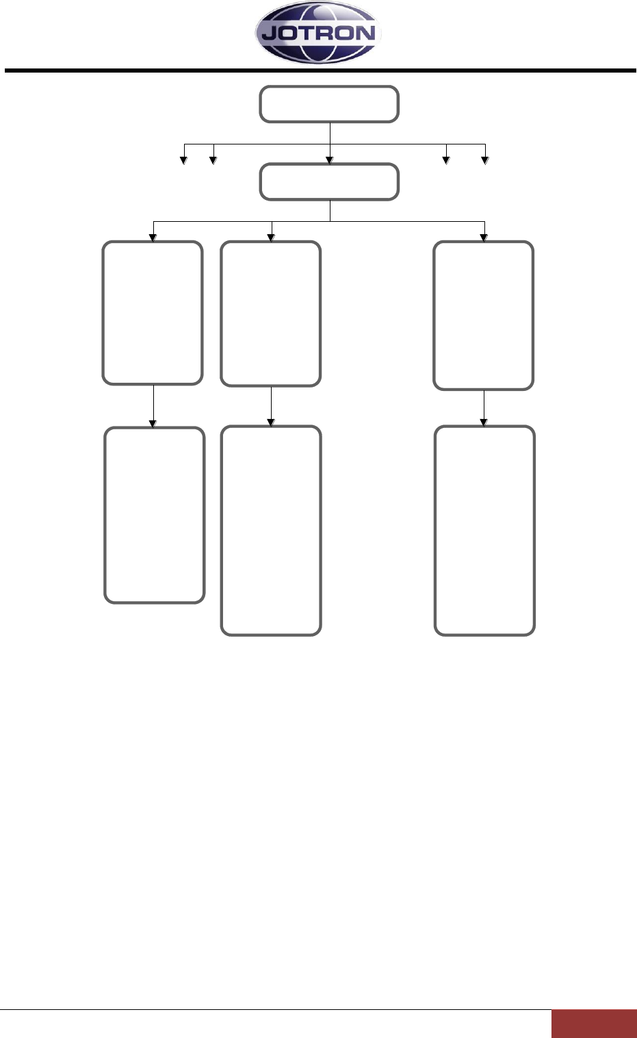
Jotron AS| TR7750C: Operators Manual ERROR CONDITIONS AND CORRECTIVE ACTIONS
Page 6-6
P/N: 84748 (pre_F)
12V
5V
3.3V
One of the voltage
readings is out of
range
High Current
Current
consumption is
above 500 mA
High
Temperature
Temperature
reading is above
+85°C
Power module
RX alarm
Action:
Replace -
RX unit (LRU)
Power module
(LRM).
Probable cause:
Failure on one or
more components
on the power
module.
Action:
Replace -
RX unit (LRU)
Power module,
Main module or RF
module (LRM).
Cause: Excessive
current
consumption in
one or more
modules.
Action:
Replace -
RX unit (LRU)
Power module,
Main module or RF
module (LRM)
Cause: Excessive
current
consumption or
defective voltage
regualtor.
Figure 6.2-1, Receiver Power module, errors and corrective actions

Jotron AS| TR7750C: Operators Manual ERROR CONDITIONS AND CORRECTIVE ACTIONS
Page 6-7
P/N: 84748 (pre_F)
LNA current
Unnormal current
consumption in the
LNA (Low Noise
Amplifier)
LO lock detect
Synthesizer is out
of lock
LO level
The LO level is
below 0dBm
RF module
RX alarm
Action:
Replace -
RX unit (LRU)
RF module (LRM)
Probable cause:
Defective
synthesizer circuits
/ VCO / TCXO
Action:
Replace -
RX unit (LRU)
RF module (LRM)
Probable cause:
Defective
synthesizer circuits
/ VCO / TCXO
Action:
Replace -
RX unit (LRU)
RF module (LRM)
Probable cause:
LNA transistor
broken because of
high RF input or
transient caused
by lightning.
IF current
Unnormal current
consumption in the
IF circuitry.
Action:
Replace -
RX unit (LRU)
RF module (LRM)
Probable cause:
Defective IF chip
on the RF board
Figure 6.2-2, Receiver RF module, errors and corrective actions
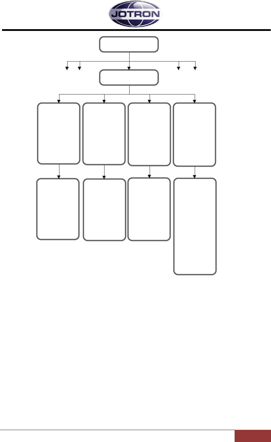
Jotron AS| TR7750C: Operators Manual ERROR CONDITIONS AND CORRECTIVE ACTIONS
Page 6-8
P/N: 84748 (pre_F)
Front
Failure on the
communication
link to the front
panel
DSP
Failure on the DSP
chip on the main
board
Codec
SPI
RemExp
BiteADC
Failure on one or
more ICs on the
main board
Ethernet
Failure on the
ethernet controller
on the main board
Main Module
RX alarm
Action:
Replace-
RX unit (LRU)
Main module
(LRM)
Probable cause:
Failure on the
ethernet chip
Action:
Replace -
RX unit (LRU)
Main module
(LRM)
Probable cause:
Failure on the
specified chip
Action:
Replace -
RX unit (LRU)
Main module
(LRM)
Probable cause:
Failure on the DSP
chip.
Action:
Replace -
RX unit (LRU)
Check connections
to the front panel,
replace front panel
(LRM)
Probable cause:
Failure on the front
panel or
connectors betw.
front panel and
main board
Figure 6.2-3, Receiver Main module, errors and corrective actions

Jotron AS| TR7750C: Operators Manual LIST OF TABLES AND FIGURES
Page 7-1
P/N: 84748 (pre_F)
7 LIST OF TABLES AND FIGURES
TABLE 1.1-1, RADIO MODELS ...................................................................................................................................... 1-1
TABLE 3.1-1, MIC/HEADSET CONNECTOR, TRANSMITTER, PIN OUT..................................................................................... 3-2
TABLE 3.2-1, LAN INTERFACE CONNECTOR, PIN OUT ....................................................................................................... 3-5
TABLE 3.2-2, AUX1 CONNECTOR, TRANSMITTER, PIN OUT ............................................................................................... 3-5
TABLE 3.2-3, AUX2 CONNECTOR, TRANSMITTER, PIN OUT ............................................................................................... 3-6
TABLE 3.2-4, REM CONNECTOR, TRANSMITTER, PIN OUT ................................................................................................. 3-6
TABLE 3.2-5, RX CONNECTOR, TRANSMITTER, PIN OUT..................................................................................................... 3-7
TABLE 3.3-1, HEADSET CONNECTOR, RECEIVER, PIN OUT .................................................................................................. 3-9
TABLE 3.4-1, LAN INTERFACE CONNECTOR, PIN OUT ..................................................................................................... 3-11
TABLE 3.4-2, AUX1 CONNECTOR, RECEIVER, PIN OUT.................................................................................................... 3-11
TABLE 3.4-3, AUX2 CONNECTOR, RECEIVER, PIN OUT.................................................................................................... 3-12
TABLE 3.4-4, REM CONNECTOR, RECEIVER, PIN OUT ..................................................................................................... 3-12
TABLE 4.1-1, INSTALLATION PROCEDURES ..................................................................................................................... 4-1
TABLE 4.6-1, TRANSCEIVER, TRANSMITTER – RECEIVER INTERCONNECTIONS ......................................................................... 4-3
TABLE 4.6-2, SETTINGS ASSOCIATED WITH THE TRANSMITTER - RECEIVER INTERCONNECTION ................................................... 4-5
TABLE 4.6-3, SETTINGS ASSOCIATED WITH MONITOR OUTPUT (TA – AUX1) .................................................................. 4-6
TABLE 4.6-4, SETTINGS ASSOCIATED WITH LINE_INPUT (TX-REM) ................................................................................. 4-8
TABLE 4.6-5, SETTINGS ASSOCIATED WITH LINE_OUTPUT (RX-REM) ............................................................................. 4-8
TABLE 4.6-6, KEY SOURCE SETTINGS .......................................................................................................................... 4-10
TABLE 4.6-7, SQUELCH OUTPUT CONFIGURATION ......................................................................................................... 4-12
TABLE 4.6-8, ALARM AND SELECT SETTINGS, TRANSMITTER AND RECEIVER ......................................................................... 4-13
TABLE 4.6-9, MISC. SETTINGS, TRANSMITTER. .............................................................................................................. 4-15
TABLE 4.7-1, TRANSCEIVER, LOCAL CONFIGURATION ..................................................................................................... 4-17
TABLE 4.7-2, TRANSCEIVER, REMOTE (2W) INTERFACE ................................................................................................. 4-19
TABLE 4.7-3, TRANSCEIVER, REMOTE (4W) INTERFACE ................................................................................................. 4-20
TABLE 4.7-4, MAIN/BACKUP CONFIGURATION, TRANSMITTERS ........................................................................................ 4-21
TABLE 4.7-5, MAIN/BACKUP CONFIGURATION, RECEIVERS .............................................................................................. 4-22
TABLE 5.2-1, USER MENU SELECTIONS TRANSMITTER - RESTRICED ACCESS LEVEL ................................................................... 5-2
TABLE 5.3-1, USER MENU SELECTIONS TRANSMITTER- OPERATOR, TECHNICIAN AND SYSOP ACCESS LEVELS ............................... 5-3
TABLE 5.4-1, SUBMENUS AVAILABLE ON THE TRANSMITTER .............................................................................................. 5-4
TABLE 5.5-1, RADIO CONTROL GROUP, TRANSMITTER ...................................................................................................... 5-8
TABLE 5.5-2, TX CONFIG GROUP, TRANSMITTER ........................................................................................................... 5-11
TABLE 5.5-3, INTERFACE CONFIG GROUP, TRANSMITTER ................................................................................................. 5-12
TABLE 5.5-4, BITE SYSTEM GROUP, TRANSMITTER ......................................................................................................... 5-14
TABLE 5.6-1, USER MENU SELECTIONS RECEIVER - RESTRICED ACCESS LEVEL ....................................................................... 5-15
TABLE 5.7-1, USER MENU SELECTIONS RECEIVER - OPERATOR, TECHNICIAN AND SYSOP ACCESS LEVELS ................................... 5-17
TABLE 5.8-1, SUBMENUS AVAILABLE ON THE RECEIVER .................................................................................................. 5-17
TABLE 5.9-1, RADIO CONTROL GROUP, RECEIVER .......................................................................................................... 5-21
TABLE 5.9-2, RX CONFIG GROUP, RECEIVER ................................................................................................................. 5-23
TABLE 5.9-3, INTERFACE CONFIG GROUP, RECEIVER ....................................................................................................... 5-25
TABLE 5.9-4, BITE SYSTEM GROUP, RECEIVER ............................................................................................................... 5-26
TABLE 6.1-1, ALARM INDICATION, TRANSMITTER NAVIGATION .......................................................................................... 6-1
TABLE 6.2-1, ALARM INDICATION, RECEIVER NAVIGATION ................................................................................................ 6-5
FIGURE 3.1-1, FRONT VIEW, TRANSMITTER UNIT, TA-7650C/25C/10C ............................................................................ 3-1
FIGURE 3.2-1, REAR VIEW, TRANSMITTER UNIT, TA-7650C/25C/10C. ............................................................................. 3-4
FIGURE 3.2-2, TRANSMITTER DC INPUT CONNECTOR, REAR VIEW ...................................................................................... 3-4
FIGURE 3.3-1, FRONT VIEW, RECEIVER UNIT, RA-7203C ................................................................................................ 3-8
FIGURE 3.4-1, REAR VIEW, RECEIVER UNIT, RA-7203C. ................................................................................................ 3-10

Jotron AS| TR7750C: Operators Manual LIST OF TABLES AND FIGURES
Page 7-2
P/N: 84748 (pre_F)
FIGURE 3.4-2, RECEIVER DC INPUT CONNECTOR, REAR VIEW .......................................................................................... 3-10
FIGURE 3.5-1, PSU-7002, FRONT VIEW ..................................................................................................................... 3-13
FIGURE 3.6-1, POWER SUPPLY UNIT - REAR VIEW .......................................................................................................... 3-14
FIGURE 3.6-2, DC INPUT CONNECTOR, PSU ................................................................................................................ 3-14
FIGURE 3.6-3, DC OUTPUT, PSU............................................................................................................................... 3-14
FIGURE 3.6-4, AC INPUT CONNECTOR, PSU ................................................................................................................ 3-15
FIGURE 4.3-1, EXAMPLES OF VARIOUS CONFIGURATIONS .................................................................................................. 4-2
FIGURE 4.6-1, AUDIO INTERFACES ON THE TRANSMITTER AND RECEIVER UNITS ..................................................................... 4-6
FIGURE 4.6-2, KEY SIGNALS ON THE TRANSMITTER UNIT ................................................................................................... 4-9
FIGURE 4.6-3, SQUELCH AND AGC SIGNALS RECEIVER UNIT ............................................................................................ 4-11
FIGURE 4.6-4, ALARM AND SELECT SIGNALS, TRANSMITTER ............................................................................................. 4-12
FIGURE 4.6-5, MISC SIGNALS, TRANSMITTER ................................................................................................................ 4-14
FIGURE 4.7-1, TRANSCEIVER, LOCAL CONFIGURATION, INTERFACING ................................................................................ 4-15
FIGURE 4.7-2, TRANSCEIVER, REMOTE CONFIGURATION WITH 2 WIRE AUDIO INTERFACE ...................................................... 4-18
FIGURE 4.7-3, TRANSCEIVER, REMOTE CONFIGURATION WITH 4 WIRE AUDIO INTERFACE ...................................................... 4-19
FIGURE 4.7-4, MAIN / BACKUP TRANSMITTER.............................................................................................................. 4-21
FIGURE 4.7-5, MAIN / BACKUP RECEIVER .................................................................................................................... 4-22
FIGURE 5.4-1, RADIO CONTROL GROUP, TRANSMITTER .................................................................................................... 5-5
FIGURE 5.4-2, TX CONFIG GROUP, TRANSMITTER ............................................................................................................ 5-5
FIGURE 5.4-3, INTERFACE CONFIG GROUP, TRANSMITTER ................................................................................................. 5-6
FIGURE 5.4-4, BITE SYSTEM GROUP, TRANSMITTER ......................................................................................................... 5-7
FIGURE 5.4-5, SYSTEM INFO GROUP, TRANSMITTER ......................................................................................................... 5-7
FIGURE 5.8-1, RADIO CONTROL GROUP, RECEIVER ........................................................................................................ 5-18
FIGURE 5.8-2, RX CONFIG GROUP, RECEIVER ............................................................................................................... 5-18
FIGURE 5.8-3, INTERFACE CONFIG GROUP, RECEIVER ..................................................................................................... 5-19
FIGURE 5.8-4, BITE SYSTEM GROUP, RECEIVER ............................................................................................................. 5-20
FIGURE 5.8-5, SYSTEM INFO GROUP, RECEIVER ............................................................................................................. 5-20
FIGURE 6.1-1, TRANSMITTER PA MODULE, ERRORS AND CORRECTIVE ACTIONS ..................................................................... 6-2
FIGURE 6.1-2, TRANSMITTER MODULATOR MODULE, ERRORS AND CORRECTIVE ACTIONS ....................................................... 6-3
FIGURE 6.1-3, TRANSMITTER MAIN MODULE, ERRORS AND CORRECTIVE ACTIONS ................................................................. 6-4
FIGURE 6.2-1, RECEIVER POWER MODULE, ERRORS AND CORRECTIVE ACTIONS ..................................................................... 6-6
FIGURE 6.2-2, RECEIVER RF MODULE, ERRORS AND CORRECTIVE ACTIONS ........................................................................... 6-7
FIGURE 6.2-3, RECEIVER MAIN MODULE, ERRORS AND CORRECTIVE ACTIONS ....................................................................... 6-8
Jotron AS| TR7750C: Operators Manual LIST OF MARITIME CHANNELS AND FREQUENCIES
Page 7-1
P/N: 84748 (pre_F)
Appendix A. LIST OF MARITIME CHANNELS AND FREQUENCIES
Channel
Designators
BASE RX
MHz
BASE TX
MHz
0
156.000
156.000
60
156.025
160.625
1
156.050
160.650
61
156.075
160.675
2
156.100
160.700
62
156.125
160.725
3
156.150
160.750
63
156.175
160.775
4
156.200
160.800
64
156.225
160.825
5
156.250
160.850
65
156.275
160.875
6
156.300
156.300
66
156.325
160.925
7
156.350
160.950
67
156.375
156.375
8
156.400
156.400
68
156.425
156.425
9
156.450
156.450
69
156.475
156.475
10
156.500
156.500
DSC 70
156.525
156.525
11
156.550
156.550
71
156.575
156.575
12
156.600
156.600
72
156.625
156.625
13
156.650
156.650
73
156.675
156.675
14
156.700
156.700
Channel
Designators
BASE RX
MHz
BASE TX
MHz
74
156.725
156.725
15
156.750
156.750
75
-
156.775
16
156.800
156.800
76
-
156.825
17
156.850
156.850
77
156.875
156.875
18
156.900
161.500
78
156.925
161.525
19
156.950
161.550
79
156.975
161.575
20
157.000
161.600
80
157.025
161.625
21
157.050
161.650
81
157.075
161.675
22
157.100
161.700
82
157.125
161.725
23
157.150
161.750
83
157.175
161.775
24
157.200
161.800
84
157.225
161.825
25
157.250
161.850
85
157.275
161.875
26
157.300
161.900
86
157.325
161.925
27
157.350
161.950
87
157.375
157.375
28
157.400
162.000
88
157.425
157.425