Jotron AS TRONAISSART TRON AIS-SART User Manual
Jotron AS TRON AIS-SART
UserManual.wiki
>
Jotron AS
>
TRONAISSART User Manual
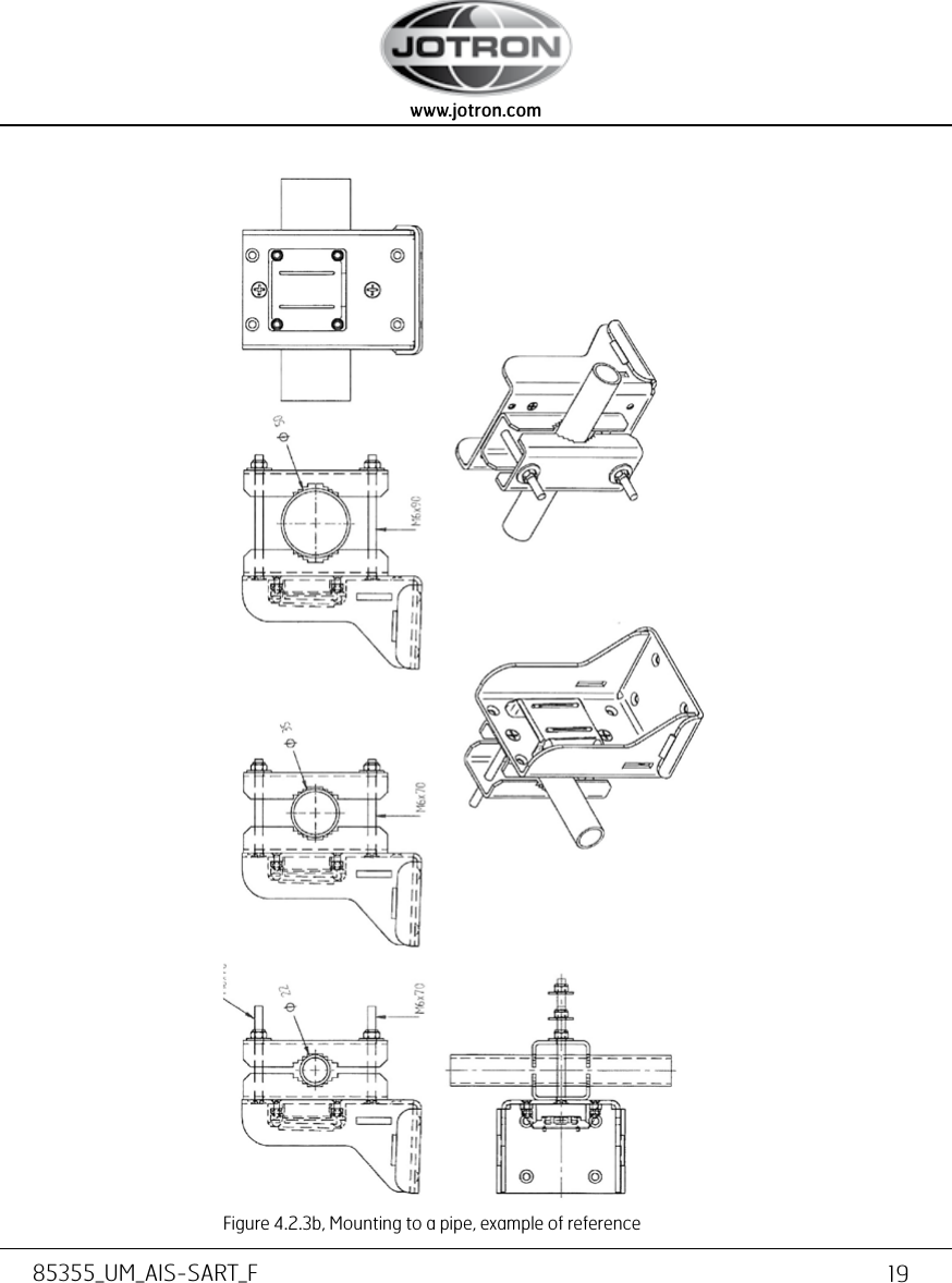
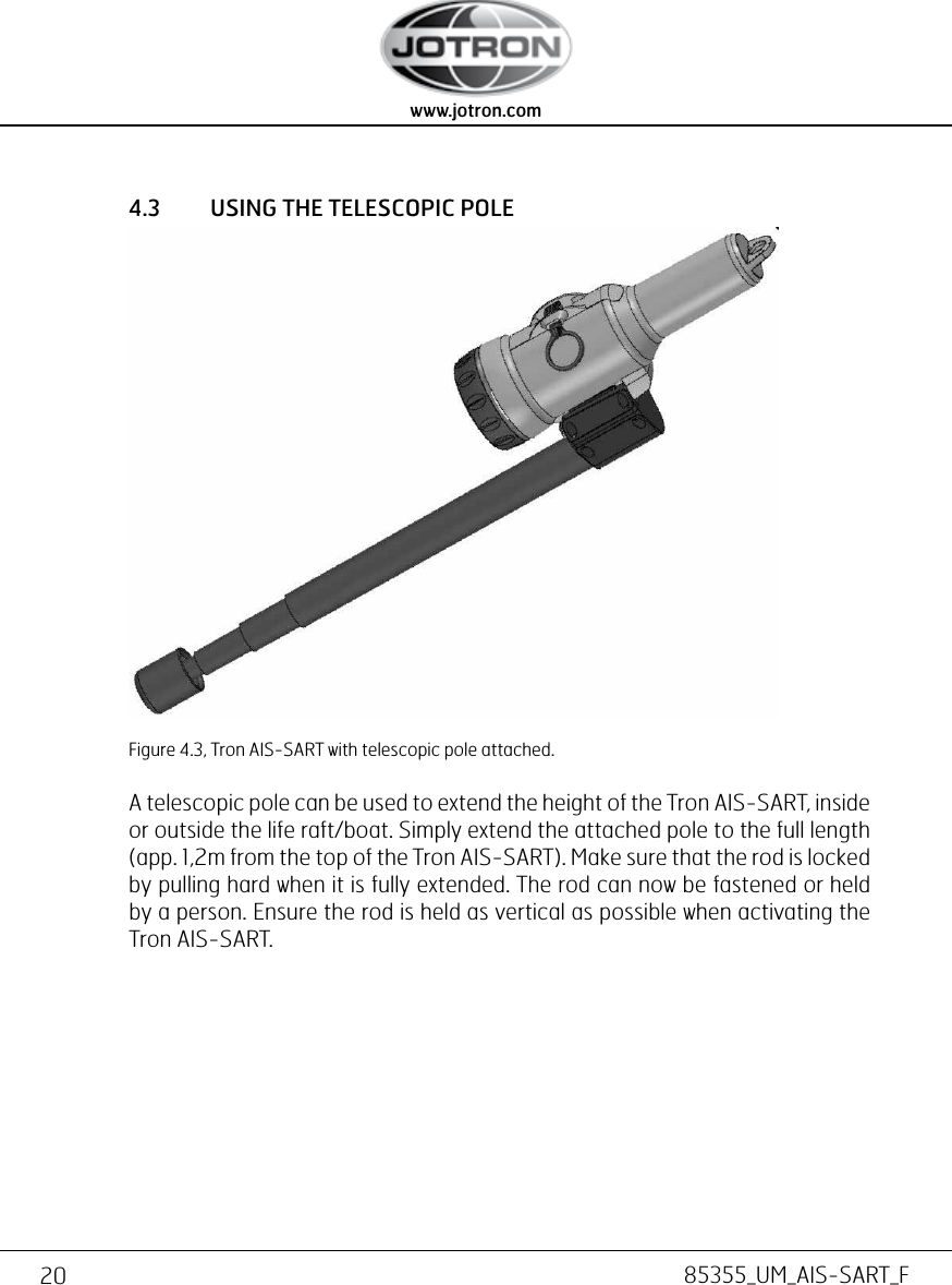
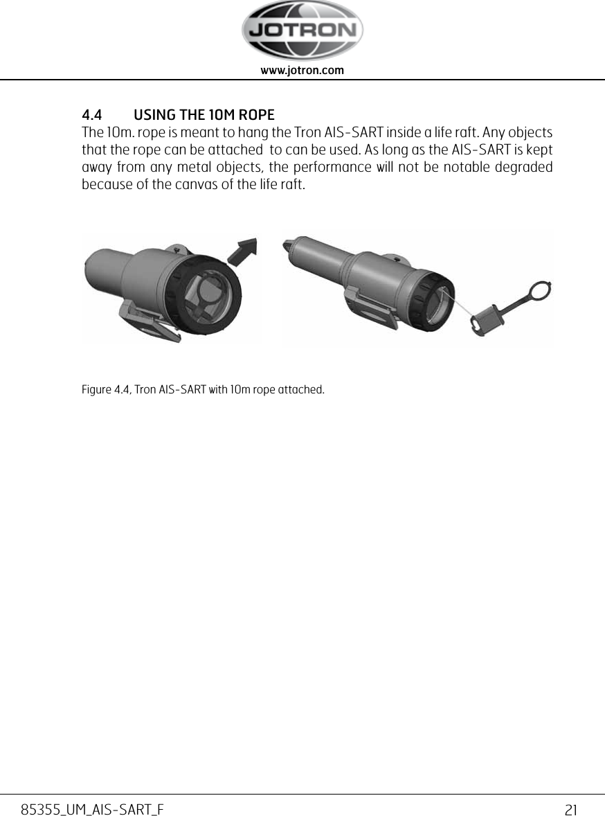
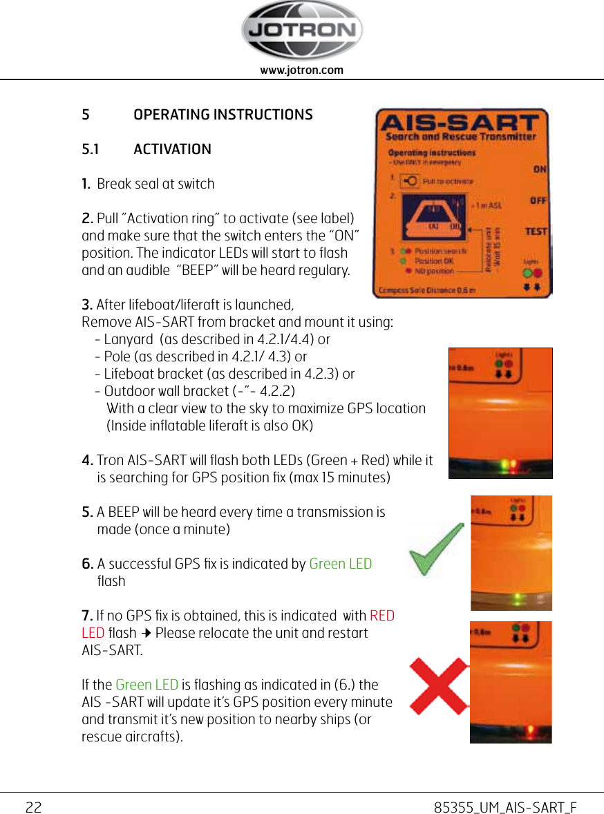
User Manual
Navigation menu
Upload a User Manual
Namespaces
Wiki Guide
HTML
PDF
Info
Views
User Manual
Discussion / Help
Navigation