Jotron AS TRONAISSART TRON AIS-SART User Manual
Jotron AS TRON AIS-SART
User Manual
USERS MANUAL
www.jotron.com
Tron AIS-SART

85355_UM_AIS-SART_F
www.jotron.com www.jotron.com
EC Declaration of Conformity, available at www.jotron.com
The serial number is identical to the user ID of the unit.
2
Abbreviations and definitions
EMC
Electromagnetic Compatibility
LED
Light Emitting Diode
PWB
Printed Wire Board
RF
Radio Frequency
AIS-SART
Search and Rescue Unit based on the AIS system
VHF
Very High Frequency
www.jotron.com
85355_UM_AIS-SART_F
www.jotron.com
3
AMEND- INCORP. DATE PAGE(S) VERSION REASON
MENT NO. BY FOR CHANGE
1 ES 16.06.09 Total: 28 A New product
2 ES 22.11.09 Page 2 B New information
3 FIT 08.12.09 Page 22-27 C Updated information
4 FIT 22.03.10 Total: 30 D Updated information
5 FIT 20.04.10 Total: 34 E Updated information
6 FIT 10.06.10 Page 28 F Updated information
7
8
Amendment Records
The information in this book has been carefully checked and is believed to be
accurate. However, no responsibility is assumed for inaccuracies.
Jotron AS reserves the right to make changes without further notice to any pro-
ducts or modules described herein to improve reliability, function or design. Jo-
tron AS does not assume any liability arising out of the application or use of the
described product.
This equipment contains CMOS integrated circuits. Observe
handling precautions to avoid static discharges which may
damage these devices.

85355_UM_AIS-SART_F
www.jotron.com www.jotron.com
Jotron AS is a prime manufacturer of safety equipment designed for rescue of human
lives and their property. For safety equipment to be effective in line with the design
parameters it is important that they are handled, stowed and maintained in compli-
ance with the manufacturers instructions. Jotron AS cannot be held responsible for
any damage caused due to incorrect use of the equipment or breach of laid down
procedures or for failure of any specific component or other parts of the equipment.
The chapter covering battery replacement (6.2.1) is added for information only. Jo-
tron AS does not take any responsibility for improper disassembling/assembling of
the beacon. We strongly recommend all service to be done by authorized Jotron
agents. In addition to normal service, Jotron agents have the necessary equipment
and knowledge to test the operational functions of the beacon. Non-original mainte-
nance and/or service parts may destroy the equipment function and performance.
WARNING / IMPORTANT
4
Battery safety data sheet
(Form: EEC directive 91/155)
(2) SAFETY ADVICE
S2 Keep out of reach of children.
S8 Keep container dry.
S26 In case of contact with eyes, rinse immediately with plenty of water and seek
medical advice.
S43 In case of fire, use D type extinguishers. Never use water.
S45 In case of accident or if you feel unwell, seek medical advice immediately
(show the label where possible).
(3) FIRST AID MEASURES
In case of contact of cell contents with eyes, flush immediately with water for 15 min. With skin,
wash with plenty of water and take off contaminated clothes. If inhaled, remove from exposure,
give oxygen, and seek medical advice.
(4) FIRE-FIGHTING MEASURES
Extinguishing media
Suitable: Type D fire extinguishers
Not to be used: Water - CO2 - Halon, dry chemical or foam extinguishers
Special exposure hazards
Generation of chlorine, sulphur dioxide, disulphur dichloride during thermal decomposition.
Special protective equipment
Use protective working boots, rubber apron and safety glasses with side shields.
www.jotron.com
85355_UM_AIS-SART_F
www.jotron.com
5

85355_UM_AIS-SART_F
www.jotron.com www.jotron.com
Table of contents
1 General description 8
1.1 Tron AIS-SART features 9
1.2 Battery module 10
2 Technical specifications 11
2.1 Electrical specifications 11
2.2 Mechanical specification 11
3 Functional description 12
3.1 General 12
3.1.1 Tron AIS-SART electronic assembly 12
3.1.2 Battery module 13
3.1.3 Bottom lid 13
4 Installation 14
4.1 Brackets 14
4.1.1 Wall bracket 14
4.1.2 Lifeboat bracket 15
4.2 Installation tips 17
4.2.1 How to use the brackets in life rafts 17
4.2.2 Installation diagram 18
4.2.3 Mounting a pipe 18
4.3 Using the telescopic pole 20
4.4 Using the 10m rope 21
5 Operating instructions 22
5.1 Activation 22
5.2 Reception on nearby vessels AIS transponders and ECS/ECDIS
or chart plotters 23
5.2.1 Reception on a non AIS-SART compliant
AIS transponder 23
5.2.2 Reception on a non AIS-SART compliant
electronic chart (ECS/ECDIS) 23
5.2.3 Reception on an AIS-SART compliant
AIS transponder 24
5.2.4 Reception on an AIS-SART compliant
electronic chart (ECS/ECDIS) 24
5.3 Test 25
5.4 Reception on nearby vessels AIS transponders and ECS/ECDIS
or chart plotters 26
5.4.1 Reception on a non AIS-SART compliant
AIS transponder 26
5.4.2 Reception on a non AIS-SART compliant
electronic chart (ECS/ECDIS) 26
6
www.jotron.com
85355_UM_AIS-SART_F
www.jotron.com
7
5.4.3 Reception on an AIS-SART compliant
AIS transponder 27
5.4.4 Reception on an AIS-SART compliant
electronic chart (ECS/ECDIS) 27
6 Maintenance and troubleshooting 28
6.1 Maintenance 28
6.2 Service 28
6.2.1 Replacing the battery module 29
6.2.2 Battery disposal 31
6.2.3 Incineration 31
6.2.4 Land filling 31
6.2.5 Recycling 31
7 Service agents 32

85355_UM_AIS-SART_F
www.jotron.com www.jotron.com
1 GENERAL DESCRIPTION
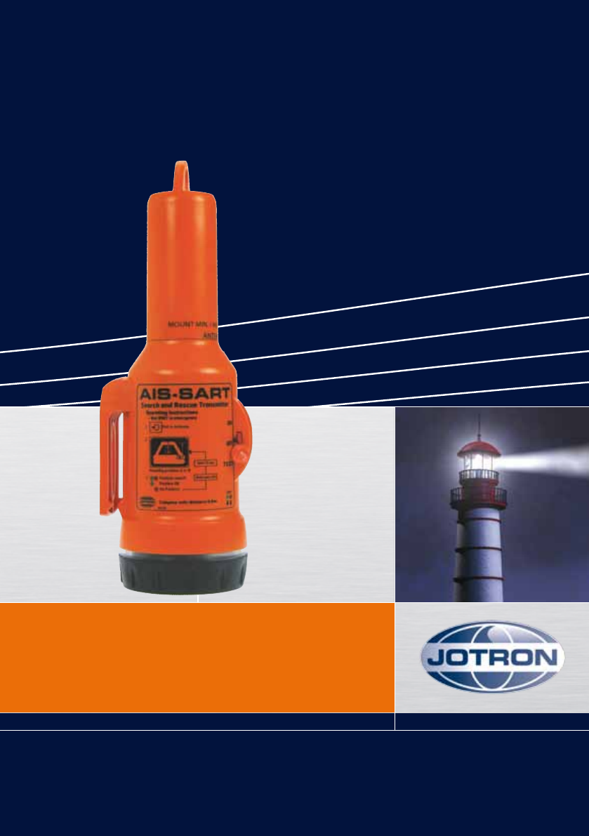
Tron AIS-SART is a battery powered AIS emergency transmitter in a sealed
waterproof enclosure consisting of:
1. Tron AIS-SART unit
2. Mounting rope for life rafts / life boats.
The Tron AIS-SART is developed by Jotron AS to meet the rules and regulations
for use on vessels and life rafts in the maritime service.
Tron AIS-SART meets the specifications for use in search and rescue opera-
tions at sea.
The operating range of the Tron AIS-SART is 7 -10 nautical miles from vessel
AIS Class-A, and more than 40 nautical miles from an airborne AIS receiver.
Tron AIS-SART is buoyant, however to obtain maximum performance, the unit
should be placed in a vertical position and as high up as possible in order to
achieve maximum coverage.
Several mounting brackets and mounting aids are available to ensure correct
mounting and use of the radar unit.
The purpose of the Tron AIS-SART is to perform a secondary alarm when
search and rescue units are searching for a life raft / lifeboat in distress. The
Tron AIS-SART includes a built-in GPS, which will help the units to pinpoint
exactly where the distressed boat is located in a larger area. This is done with
the help of the AIS on the searching ship or helicopter. When started, the Tron
AIS-SART sends its position data in an ordinary AIS message.
In addition the Tron AIS-SART sends a safety text message every forth minute,
containing text: “AIS SART”. This will be received by other AIS systems within
the range.
The batteries of the Tron AIS-SART will last at least 96 hours when activated.
8
www.jotron.com
85355_UM_AIS-SART_F
www.jotron.com
9
To save battery capacity in case of a situation where the unit is needed, the use
should be limited to tests and emergency situations.
1.1 TRON AIS-SART FEATURES
Watertight:
Tron AIS-SART is watertight to a depth of minimum 1 meter.
Buoyant:
Tron AIS-SART is buoyant in case the unit is accidentally dropped into the
water. To increase coverage the AIS-SART should always be held or mounted
as high as possible.
Rugged design:
The Tron AIS-SART will withstand a drop from 20 meters into the water. It is
resistant to seawater, oil and sunlight.
Handling:
Tron AIS-SART is designed for easy operation, with a brief operating instruction
printed on the unit. It comes standard with a 10 meter rope and a shackle hook
to be used for hanging the AIS-SART on the inside of a life raft.
Indicators:
Tron AIS-SART is equipped with two colored LEDs, one green and one red. The
LEDs will give visual status of operation and faults. In addition a built in buzzer
beeps regularly to indicate operation.
Table 1 Functions
FUNCTION INDICATOR BUZZER
GPS position fix OK Green LED flashes Regularly beep
Searching for Red and Green Regularly beep
GPS fix LED flashes
No GPS fix, count Red LED flashes Regularly beep
number of flashes.
85355_UM_AIS-SART_F
www.jotron.com www.jotron.com
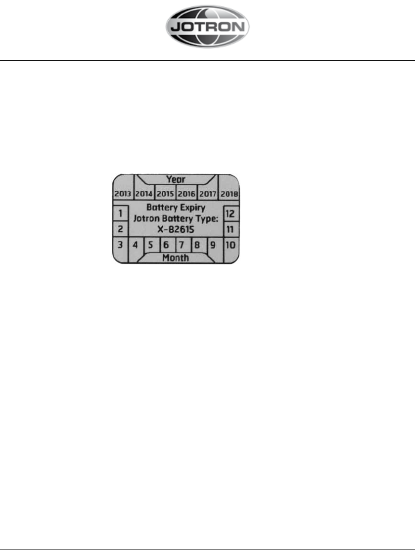
1.2 BATTERY MODULE
The Battery Module comprises of two C-size Lithium batteries, a battery housing, a connector and
cables. The battery module is to be replaced every 5th year. A battery expiry label on the Tron AIS-
SART housing displays the expiry date.
Only original Jotron batteries, partno 82616, are allowed to be used with this product
A new battery comes complete with cable and connector.
10

www.jotron.com
85355_UM_AIS-SART_F
www.jotron.com
2 TECHNICAL SPECIFICATIONS
2.1 ELECTRICAL SPECIFICATIONS
Frequency: 161.975MHz and 162.025MHz
Temperature range: Operating: -20°C to +55°C
Storage: -30°C to +70°C
Radiated power (e.i.r.p): 1W (30dBm ± 3dB)
Antenna pattern: Vertical polarization
Battery: Two C-size SAFT LSH 14 light Lithium batteries,
5 years service life + 18 month storage
(from date of manufacture)
Battery capacity: 96 hours operation when activated at -20°C
5 years storage
2.2 MECHANICAL SPECIFICATION
Materials used:
- Wall bracket (82756): ASA
- Housing (82738): PC GF10
- Lightcover (82739): PC
- Impact Ring (82740): TPE
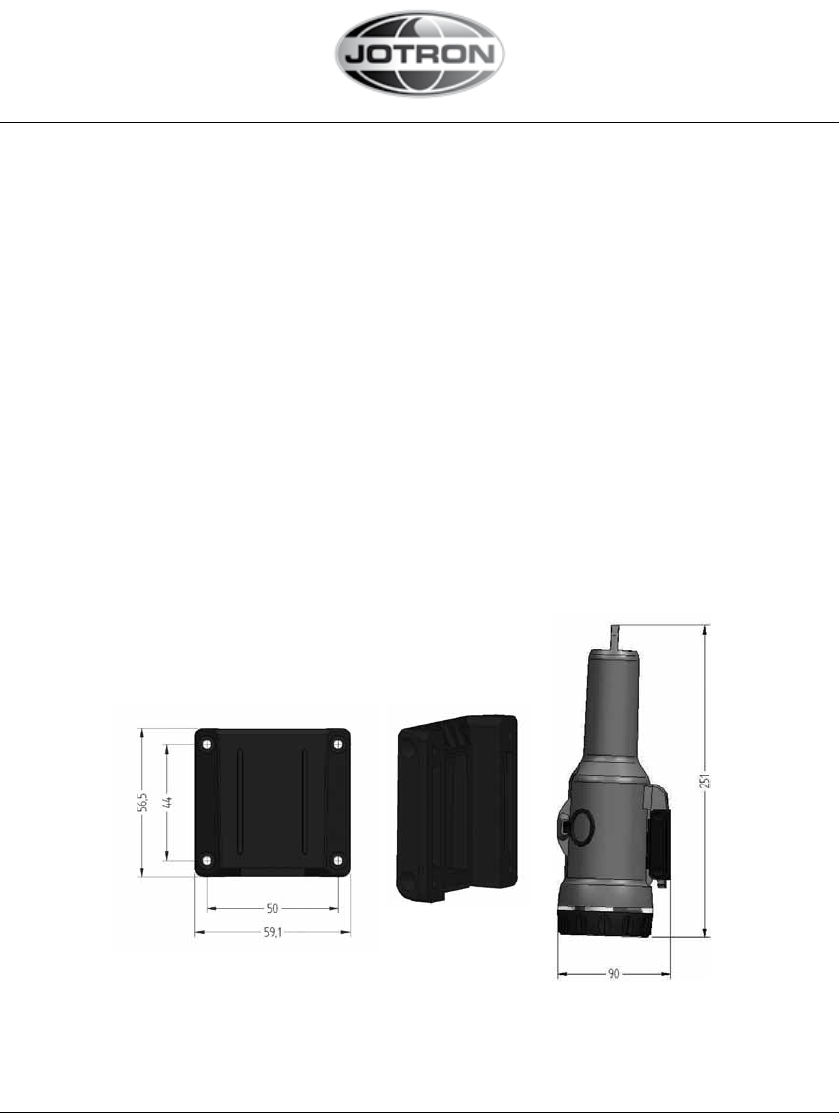
Unit dimensions:
Max diameter: 89 mm
Length: 251 mm
Weight: 450g
Unit with standard storage bracket:
Max diameter: 90 mm
Length: 251 mm
11
85355_UM_AIS-SART_F
www.jotron.com www.jotron.com
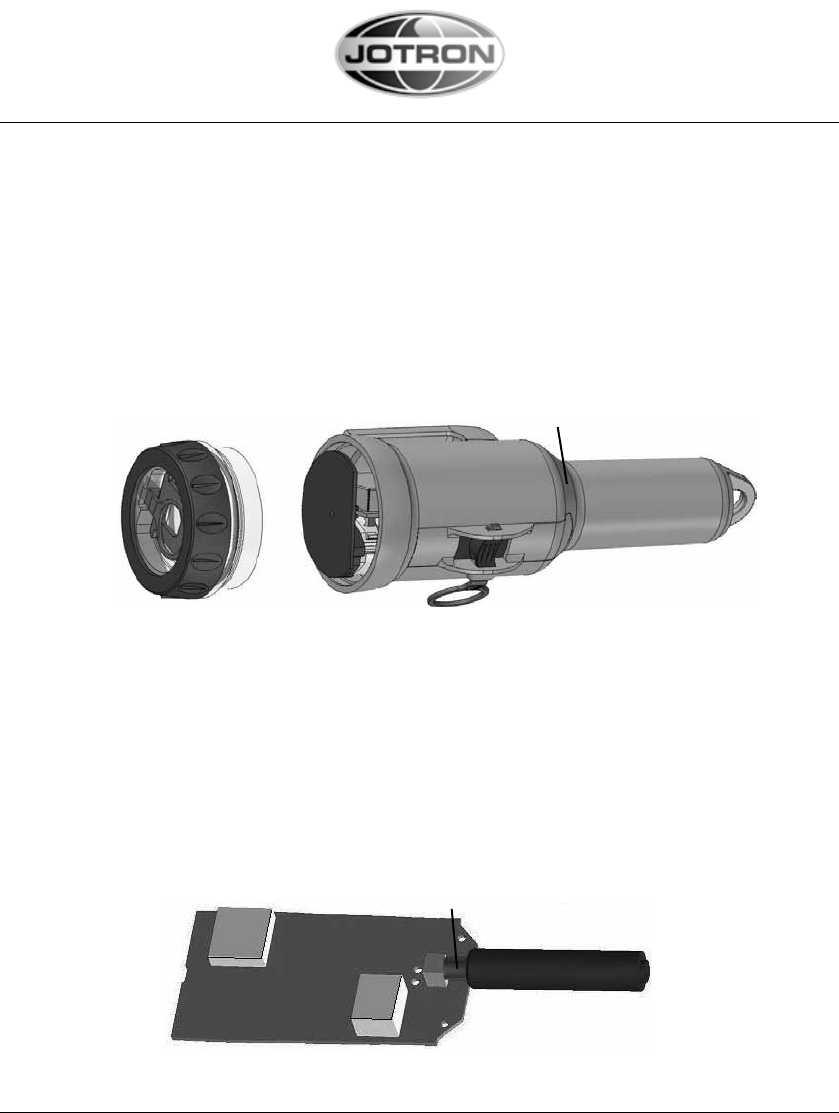
3 FUNCTIONAL DESCRIPTION
3.1 GENERAL
Tron AIS-SART consists of a housing sealed at the lower end with a bottom lid
and may be split into the following main parts:
1. Bottom lid.
2. Housing with Tron AIS-SART electronic assembly and battery module.
The housing is made of polycarbonate.
3. Base of antenna
Figure 3.1, Tron AIS-SART disassembled
3.1.1 TRANSMITTER MODULE
Tron AIS-SART transmitter module is inserted into the Tron AIS-SART housing.
It consists of the main board, antenna and two screen boxes which is mounted
in the housing. It can be divided into the following sections:
1. Transmitter module
2. Antenna
3. Screen Boxes
4. Base of antenna
Figure 3.1.1 Tron AIS-SART Transmitter module
12
1 2
1 2
3
4
3
www.jotron.com
85355_UM_AIS-SART_F
www.jotron.com
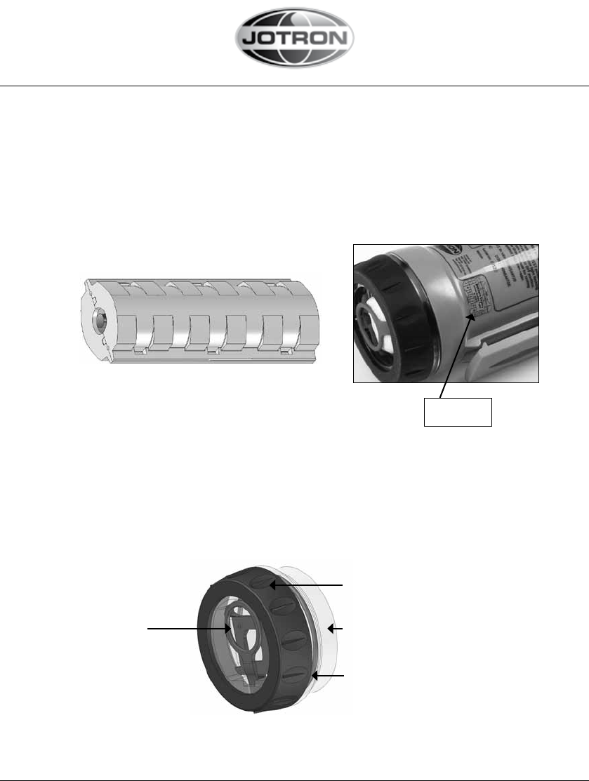
3.1.2 BATTERY MODULE (see page 26 for decription of battery change)
The battery module is inserted into the Tron AIS-SART housing.
A battery expiry label on the Tron AIS-SART housing displays the battery expiry
date.
A new battery module comes complete with cable and connector and can be
changed by opening the bottom lid at of the Tron AIS-SART.
Figure 3.1.2 TRON AIS-SART BATTERY
- module without cable and connector
3.1.3 BOTTOM LID
The Bottom lid includes four items:
1. The winder hook
2. The screw ring
3. The light tower
4. The O-ring
Figure 3.1.3 Bottom lid
13
1
2
3
4
Battery expiry
label
85355_UM_AIS-SART_F
www.jotron.com www.jotron.com
4 INSTALLATION
Tron AIS-SART can be mounted several ways, depending on the options avai-
lable. As a general rule, the transponder should be mounted as high as possible
to increase line of sight to the search and rescue units.
Metal objects close to the transponder should be avoided, these will limit the
performance in the directions they are located.
4.1 BRACKETS
There are two different mounting brackets available.
1. Wall bracket
2. Lifeboat bracket
3. Pole bracket
4.1.1 WALL BRACKET
A wall bracket is delivered with the Tron AIS-SART and should be used for sto-
rage of the unit. The bracket should preferably be mounted in a vertical posi-
tion and in a place where the Tron AIS-SART is easily available in case of an
emergency.
Figure 4.1.1a, wall bracket. Figure 4.1.1b, Tron AIS-SART
mounted in wall bracket.
The bracket should be mounted with four screws (Ø 4 mm).
14
www.jotron.com
85355_UM_AIS-SART_F
www.jotron.com
15
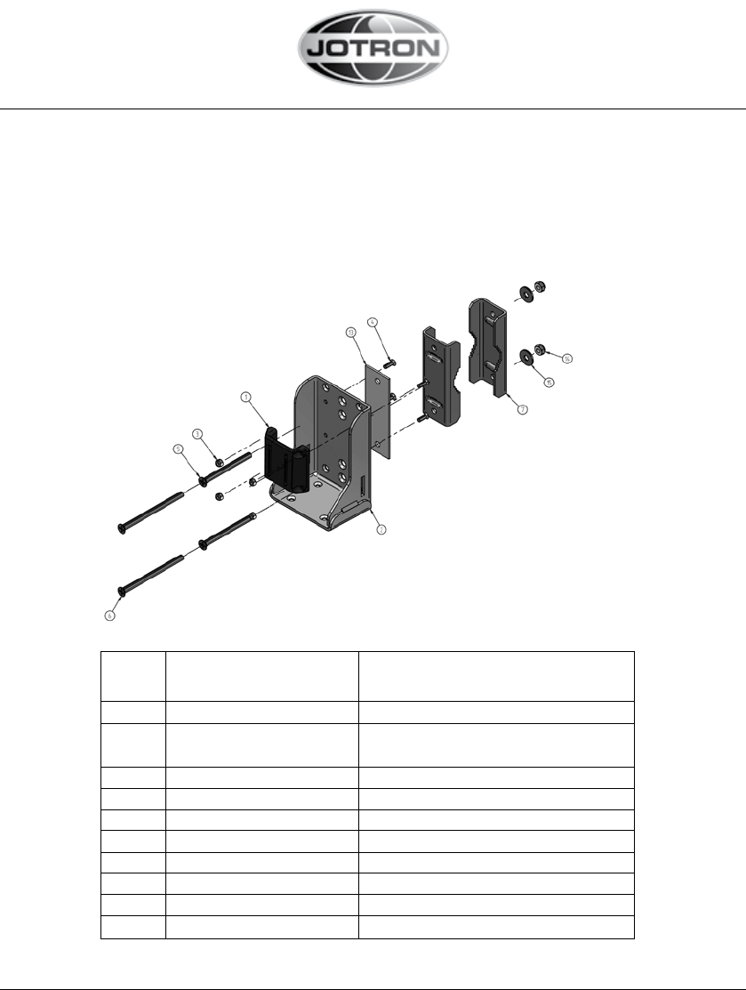
4.1.2 LIFEBOAT BRACKET
The outdoor lifeboat bracket should be mounted vertically on the roof of the
lifeboat (as high as possible).
Activate the unit and put it into the bracket. Secure the transponder to the
bracket. The bracket will fit a pipe with a maximum diameter of 50mm.
Figure 4.1.2a, Lifeboat bracket.
Item Document Title
nr. nr.
1 M-82746 WALL BRACKET
2 M-84163_WELDAMENT M-84163_BRACKET_UNIVERSAL_
WELDAMENT D 1
3 M-80312 Nut nylock M4 DIN 985
4 M-84676 Screw, DIN965 - Pozidrive M4x12
5 M-84854 Screw, DIN965 - Pozidrive M6x70
6 M-84855 Screw, DIN965 - Pozidrive M6x90
7 M-84838 PIPE CLAMP
13 M-84875 WASHER PLATE
14 M-91469 Nut nylock M6 DIN 985
15 M-82275 WASHER, DIN9021 Ø6mm
85355_UM_AIS-SART_F
www.jotron.com www.jotron.com
Figure 4.1.2b, Tron AIS-SART lifeboat bracket. Figure 4.1.2c, AIS-SART to
put into lifeboat bracket.
Figure 4.1.2d Example of Mounting the Bracket on
Interior and Exterior Walls of a Lifeboat
16
www.jotron.com
85355_UM_AIS-SART_F
www.jotron.com
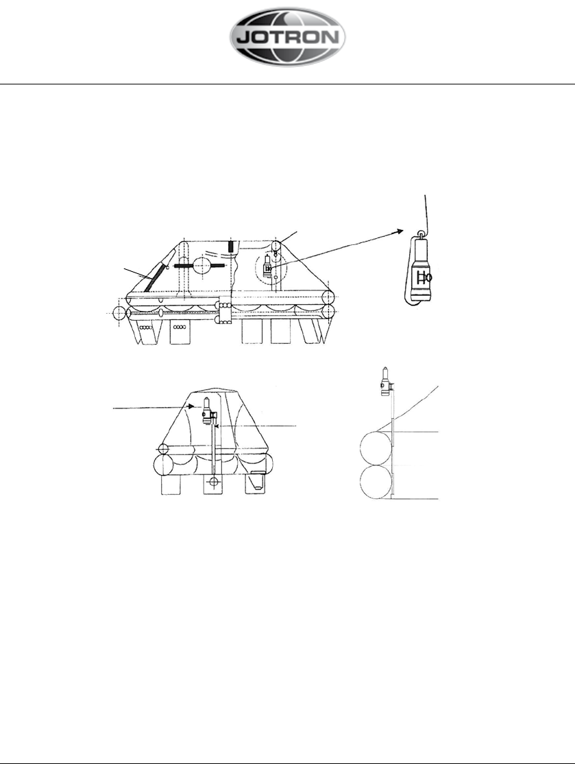
Entrance/Exit
Tent air tube
AIS-SART main unit
Hang the AIS-SART from the AIS-SART
installation seat or radar reflector
Pole
AIS-SART main unit
Figure 4.2.1, How to mount Tron AIS-SART to a liferaft
4.2 INSTALLATION TIPS
4.2.1 HOW TO USE THE BRACKET IN LIFE RAFTS
17
85355_UM_AIS-SART_F
www.jotron.com www.jotron.com
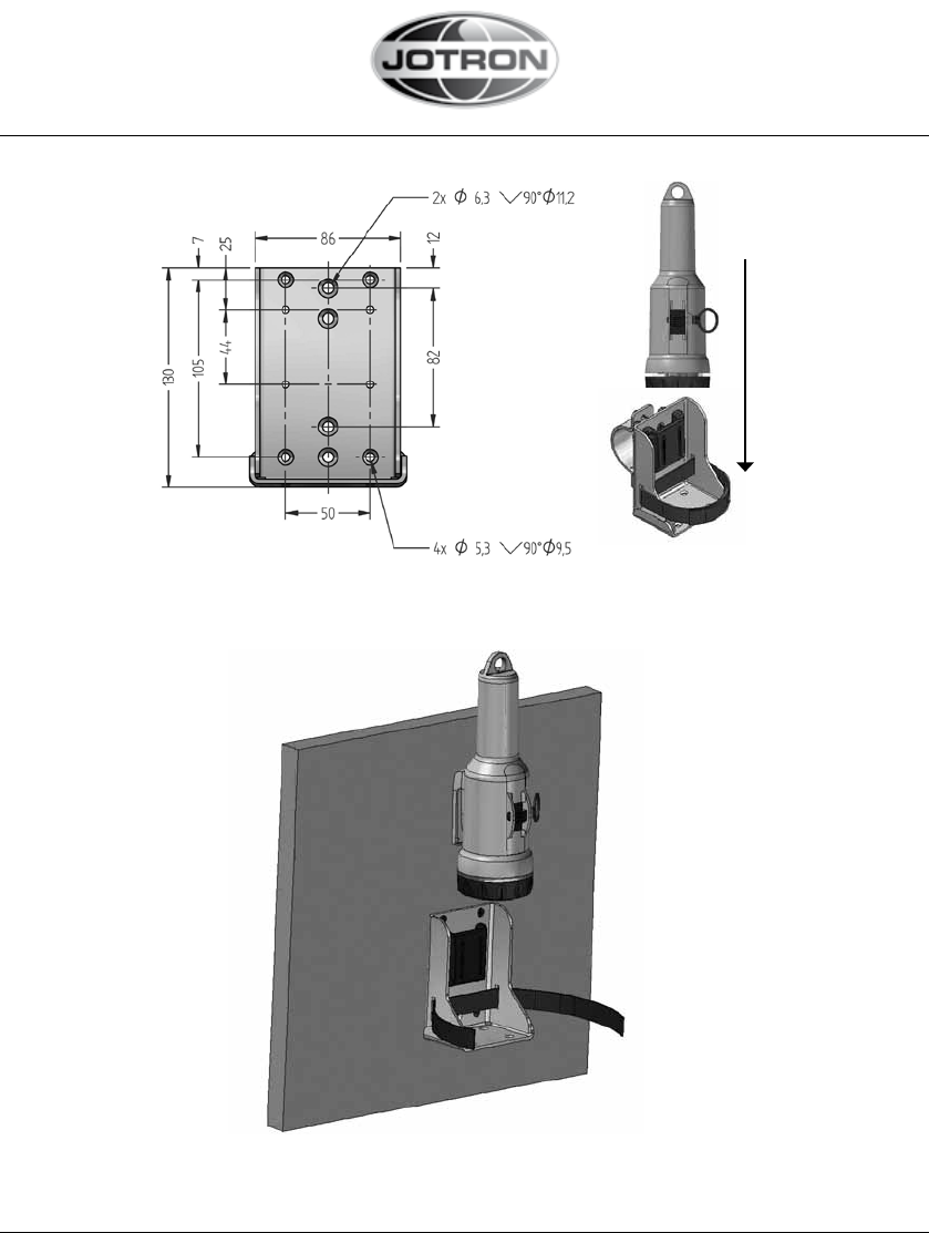
4.2.2 INSTALLATION DIAGRAM
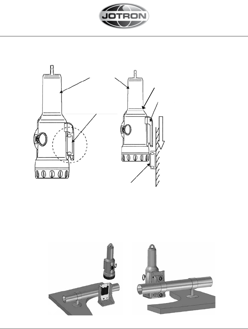
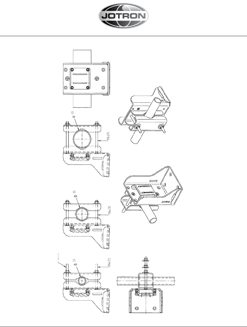
4.2.3 MOUNTING TO A PIPE
Tron AIS-SART main unit
The state when inserted
into the wall bracket
Clip
Insert the clip of the AIS-
SART main unit into the
wall bracket from a top
Wall
Wall bracket:
- For mounting, use 3 mm
screws or wood screws,
depending on the wall type
Figure 4.2.2, Installation diagram of the AIS-SART main unit and the wall bracket
Figure 4.2.3a, Examples of pipe mounting
18
The base of antenna
www.jotron.com
85355_UM_AIS-SART_F
www.jotron.com
Figure 4.2.3b, Mounting to a pipe, example of reference
19
85355_UM_AIS-SART_F
www.jotron.com www.jotron.com
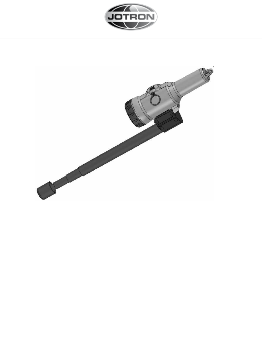
4.3 USING THE TELESCOPIC POLE
Figure 4.3, Tron AIS-SART with telescopic pole attached.
A telescopic pole can be used to extend the height of the Tron AIS-SART, inside
or outside the life raft/boat. Simply extend the attached pole to the full length
(app. 1,2m from the top of the Tron AIS-SART). Make sure that the rod is locked
by pulling hard when it is fully extended. The rod can now be fastened or held
by a person. Ensure the rod is held as vertical as possible when activating the
Tron AIS-SART.
20
www.jotron.com
85355_UM_AIS-SART_F
www.jotron.com
21
4.4 USING THE 10M ROPE
The 10m. rope is meant to hang the Tron AIS-SART inside a life raft. Any objects
that the rope can be attached to can be used. As long as the AIS-SART is kept
away from any metal objects, the performance will not be notable degraded
because of the canvas of the life raft.
Figure 4.4, Tron AIS-SART with 10m rope attached.
85355_UM_AIS-SART_F
www.jotron.com www.jotron.com
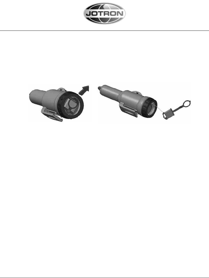
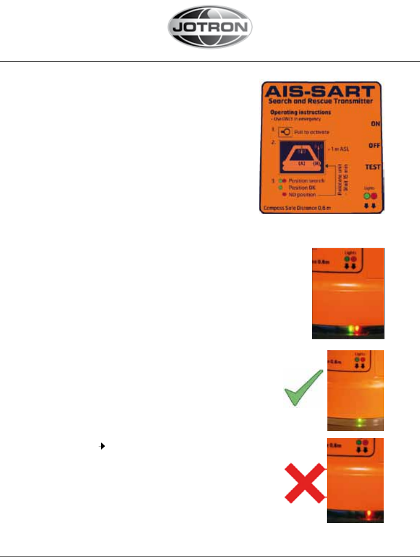
5 OPERATING INSTRUCTIONS
5.1 ACTIVATION
1. Break seal at switch
2. Pull ”Activation ring” to activate (see label)
and make sure that the switch enters the “ON”
position. The indicator LEDs will start to flash
and an audible “BEEP” will be heard regulary.
3. After lifeboat/liferaft is launched,
Remove AIS-SART from bracket and mount it using:
- Lanyard (as described in 4.2.1/4.4) or
- Pole (as described in 4.2.1/ 4.3) or
- Lifeboat bracket (as described in 4.2.3) or
- Outdoor wall bracket (-”- 4.2.2)
With a clear view to the sky to maximize GPS location
(Inside inflatable liferaft is also OK)
4. Tron AIS-SART will flash both LEDs (Green + Red) while it
is searching for GPS position fix (max 15 minutes)
5. A BEEP will be heard every time a transmission is
made (once a minute)
6. A successful GPS fix is indicated by Green LED
flash
7. If no GPS fix is obtained, this is indicated with RED
LED flash Please relocate the unit and restart
AIS-SART.
If the Green LED is flashing as indicated in (6.) the
AIS -SART will update it’s GPS position every minute
and transmit it’s new position to nearby ships (or
rescue aircrafts).
22
www.jotron.com
85355_UM_AIS-SART_F
www.jotron.com
23
5.2 RECEPTION ON NEARBY VESSELS AIS TRANSPONDERS AND
ECS/ECDIS OR CHART PLOTTERS
Today, most AIS transponders installed are not compliant with AIS-SART, but
will still receive them as another ship, both with ID code, Position, Range, Bea-
ring, and Text message
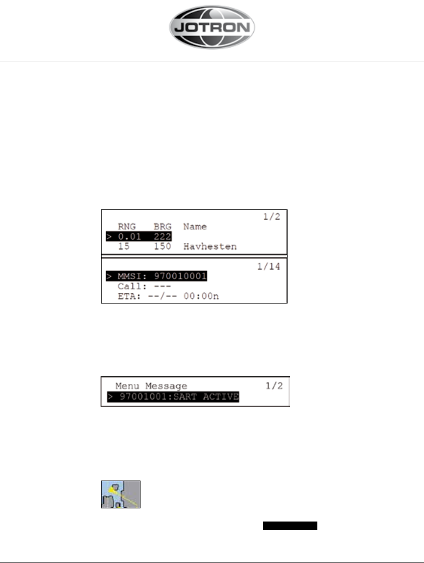
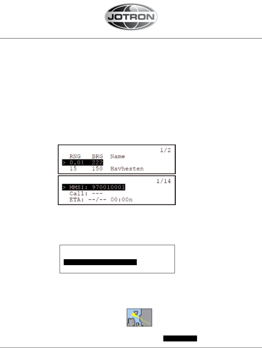
5.2.1 RECEPTION ON A NON AIS-SART COMPLIANT AIS TRANSPONDER:
- will be shown as a ship without name, with MMSI (here
“ID code”), range, bearing and position:
- Some AIS transponders will show MMSI (here “ID code”) when no
vessel name is received
- In addition, a text message will be received:
5.2.2 RECEPTION AN A NON AIS-SART COMPLIANT ELECTRONIC
CHART (ECS/ECDIS):
- will be shown as a ship
- with the same text message received: SART ACTIVE
85355_UM_AIS-SART_F
www.jotron.com www.jotron.com
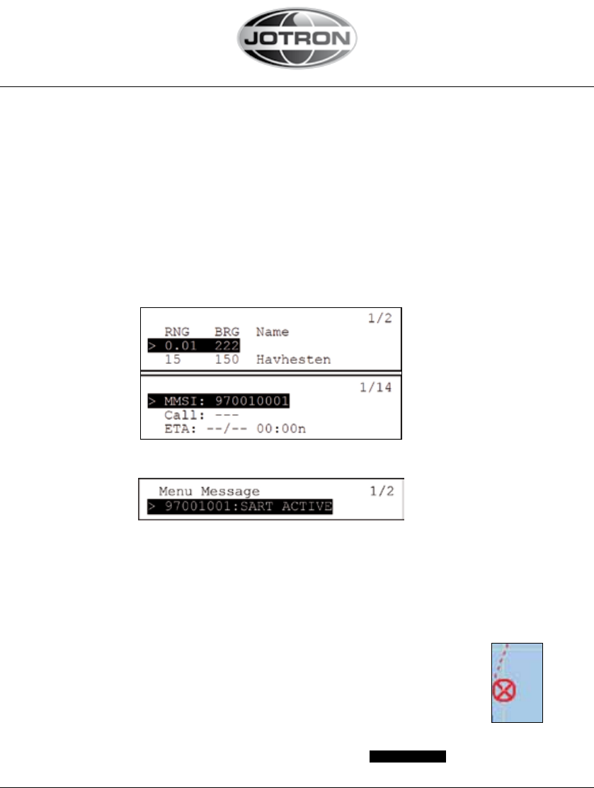
5.2.3. RECEPTION ON AN AIS-SART COMPLIANT AIS TRANSPONDER:
The requirement to have a AIS-SART compliant AIS transponder, is not ready
yet, not when it will be implemented, nor what the final requirement will be. But
there are drafts of new AIS specification, IEC 61993-2 (Ed.2) which states:
By default the target list is auto-sorted in ascending range except the
nearest active AIS SART or, if supported, other target of interest shall be
displayed at the top of the list.
• will be possibly be shown with the text “SART ACTIVE” as “vessel name”
with range, bearing and position:
• In addition, a text message will be received:
5.2.4. RECEPTION ON AN AIS-SART COMPLIANT ELECTRONIC CHART
(ECS/ECDIS):
Even though the AIS transponder is not AIS-SART compliant, the electronic
chart may show the correct symbol when receiving an AIS-SART in “Test” or
“Active” if it is updated to the latest revisions defined below:
- will be shown with this special symbol (red) as defined here:
SN.1/Circ.243/Add.1 and in lates revision of IEC 62388:
- An AIS Search And Rescue Transponder (SART) shall be presented as
a circle with an “X” inscribed inside it. The circle shall be 5 millimetres in
diameter. The symbol shall be drawn using a thick dashed line style with
the colour red. The symbol shall flash until acknowledged by the user.
Once acknowledged, the symbol shall cease flashing.
- with the same text message received: SART ACTIVE
24
www.jotron.com
85355_UM_AIS-SART_F
www.jotron.com
Number of red LED flash Fault indication
2 Transmit power failure
3 Low battery
4 Transmit frequency error
5 User ID not programmed
6 Undefined, contact Jotron
7 Internal communication error
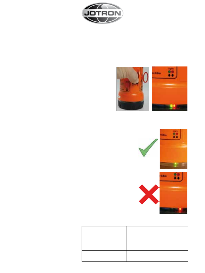
5.3 TEST
1. Test must be conducted outdoors with a clear view to the sky to maximize
GPS location.
2. Move the switch to “TEST” position
until the LEDs start flashing.
Tron AIS-SART will now run through a self
test procedure. If a Red LED flashes, it
is indication of critical faults. *See table
below for error codes.
3. Release the switch when both LEDs start flashing.
The unit will now search for GPS position for maxi-
mum 15 minutes.
4. A successful test is indicated by 15 second beep
and Green LED . See next page for description of in-
dication on a AIS transponder/ Electronic chart etc
5. An unsuccessful test is indicated by 15 second
beep and Red LED. Please relocate the unit and
restart test.
6. To cancel ongoing test, hold the switch on the
Tron AIS-SART in the “TEST” position until the buz-
zer starts to beep.
*Error codes if
RED flash in“2.”
25
85355_UM_AIS-SART_F
www.jotron.com www.jotron.com
5.4 RECEPTION ON NEARBY VESSELS AIS TRANSPONDERS AND
ECS/ECDIS OR CHART PLOTTERS
To conduct a complete test of a Tron AIS-SART, reception on the ships AIS
transponder should also be checked. Today, most AIS transponders installed
are not compliant with AIS-SART, but will still receive them as another ship,
both with ID code, Position, Range, Bearing, and Text message
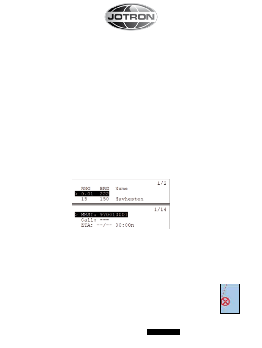
5.4.1 RECEPTION AN A NON AIS-SART COMPLIANT AIS
TRANSPONDER:
- will be shown as a ship without name, with MMSI (here “ID code”),
range, bearing and position:
- Some AIS transponders will show MMSI (here “ID code”) when no
vessel name is received
- In addition, a text message will be received:
5.4.1 RECEPTION AN A NON AIS-SART COMPLIANT ELECTRONIC
CHART (ECS/ECDIS):
- will be shown as a ship
- with the same text message received:
Menu Message 1/2
> 97001001:SART TEST
Menu Message 1/2
> 97001001:SART TEST
26
www.jotron.com
85355_UM_AIS-SART_F
www.jotron.com
5.4.3 RECEPTION AN A AIS-SART COMPLIANT AIS TRANSPONDER:
The requirement to have a AIS-SART compliant AIS transponder, is not ready
yet, not when it will be implemented, nor what the final requirement will be. But
there are drafts of new AIS specification, IEC 61993-2 (Ed.2) which states:
By default the target list is auto-sorted in ascending range except the nearest
active AIS SART or, if supported, other target of interest shall be displayed at
the top of the list.
In addition, there will be possibly automatic filtering of AIS SART’s in TEST since
the test will send text messages to all nearby ships (within VHF range). There
are today two suggestions on how to implement the filtering:
1. Prior to test the AIS-SART on your own ship, you must enter “Configuration
menu” of your own AIS transponder, and turn on “Show AIS-SART Test”
2. Only receive AIS-SART in “Test” within a very limited range
- will be possibly be shown with the text “SART TEST” as “vessel name” with
range, bearing and position:
- In addition, a text message will be received:
5.4.3 RECEPTION AN A AIS-SART COMPLIANT ELECTRONIC CHART
(ECS/ECDIS):
Even though the AIS transponder is not AIS-SART compliant, the electronic
chart may show the correct symbol when receiving an AIS-SART in “Test” or
“Active” if it is updated to the latest revisions defined below:
- will be shown with this special symbol as defined here:
SN.1/Circ.243/Add.1 and in lates revision of IEC 62388:
- An AIS Search And Rescue Transponder (SART) shall be presented as a circle
with an “X” inscribed inside it. The circle shall be 5 millimetres in diameter. The
symbol shall be drawn using a thick dashed line style with the colour red. The sym
bol shall flash until acknowledged by the user.Once acknowledged, the symbol
shall cease flashing.
- with the same text message received:
Menu Message 1/2
> 97001001:SART TEST
27

85355_UM_AIS-SART_F
www.jotron.com www.jotron.com
6 MAINTENANCE AND TROUBLESHOOTING
6.1 MAINTENANCE
Tron AIS-SART requires the following maintenance:
Every month
The unit should be taken out of its bracket and tested using the procedure in
chapter 5.1.
Every 5 years
The battery unit must be replaced every 5 year. Storage of batteries over a long
period of time will reduce their capacity. To ensure long and reliable operation
the battery unit must be replaced every 5 year. The battery replacement can be
performed on board using the procedure in chapter 6.2.1.
6.2 SERVICE
Warranty Service
All goods sold by the Company are warranted to be free from defect in work-
manship and material for the period of twenty-four (24) months from the date
of delivery (unless stated otherwise and confirmed in writings). For further infor-
mation, see pos.6 “Guarantee” in our Terms and Conditions of Sale.
Provided that the unit(s) returned for repair is under warranty, man-hour cost
and material cost will be covered by Jotron. This is not valid if the customer has
tried to repair, modify or rebuild the unit, or if the unit has been exposed to en-
vironmental conditions outside the specifications for the unit.
If the unit is in need of repair, please return it carriage paid to the agent that you
purchased it from.
Additional costs not related to repair/replacement of the unit will not be
covered.
28
www.jotron.com
85355_UM_AIS-SART_F
www.jotron.com
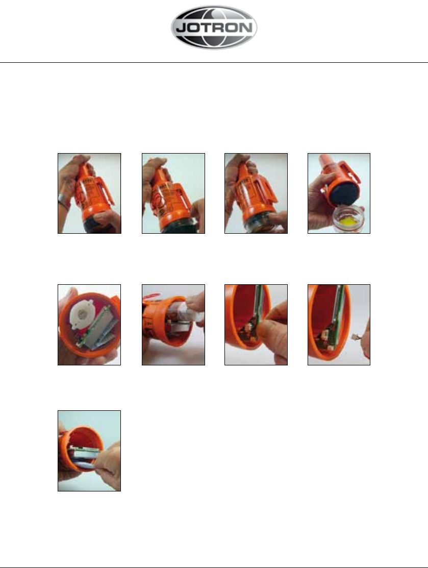
6.2.1 REPLACING THE BATTERY MODULE
Below is a description on how to change batteries on AIS-SART
Dissasembly:
Twist the rubber grip
anti-clockwise to
remove the lid
It might be difficult
to remove the lid. If
so, remove the rub-
ber grip first
And then twist off
the lid
Opened
Rubber holder below
battery and electro-
nics removed
Pull out the battery Pull out the cable from connector
Remove old Silaca
gel bags
29
85355_UM_AIS-SART_F
www.jotron.com www.jotron.com
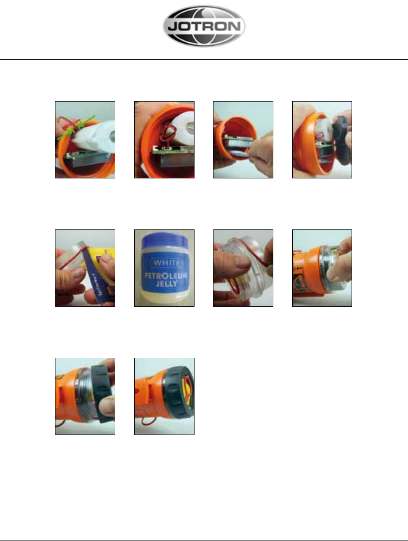
Install the new bat-
tery. Make sure the
cable is within the
guide
Connect cable to
electronics,
black= left,
red= right
Add 2x5 g Silica
gel bags
Assembly:
Mount rubber
holder
Remove old O-ring
using a Credit Card
Use acid-free
Vaseline on the
new O-ring
Fit the new
O-ring
Reinstall lid- tigh-
ten without tools
Replace the rub-
ber grip
Assembly com-
pleted
30
www.jotron.com
85355_UM_AIS-SART_F
www.jotron.com
6.2.2 BATTERY DISPOSAL
Dispose in accordance with applicable regulations, which vary from country
to country.(In most countries, the disposal of used batteries is regulated and
end-users are invited to dispose of them correctly, through non-profit organi-
zations, mandated by local governments or organized on a voluntary basis by
professionals). Lithium batteries should have their terminals insulated prior to
disposal.
6.2.3 INCINERATION
Incineration should never be performed by battery users but by trained profes-
sionals in authorized facilities with proper gas and fumes treatment.
6.2.4 LAND FILLING
Leachability regulations (mg/l)
6.2.5 RECYCLING
Send to authorized recycling facilities, through a licensed waste carrier.
Component Leachability EC limit EPA Other*
Iron 100 5
Nickel 100 500 2 0,5
* Applicable to France
31

85355_UM_AIS-SART_F
www.jotron.com
7 SERVICE AGENTS
Please look at www.jotron.com for Marine Service Agents.
Jotron Group subsidiary companies:
Jotron UK Ltd.
Crosland Park
Cramlington
NE23 1LA
United Kingdom
Tel +44 1670 712000
Fax +44 1670 590265
E-mail: sales@jotron.com
Jotron Asia Pte. Ltd.
Changi Logistics Center
19 Loyang Way #04-26
Singapore 508724
Tel +65 65426350
Fax +65 65429415
E-mail: sales@jotron.com
Jotron USA, Inc.
10645 Richmond Avenue, Suite 140
Houston, TX 77042
USA
Tel +1 713 268 1061
Fax +1 713 268 1062
E-mail: sales@jotron.com
32
www.jotron.com

www.jotron.com