Jotron Electronics A S TRON40S (See comments below) User Manual Technical Handbook
Jotron Electronics A/S (See comments below) Technical Handbook
Contents
- 1. Technical Handbook
- 2. Operators Manual
Technical Handbook

Technical Handbook
Tron 40S
US version
406 MHz EPIRB
JOTRON electronics a.s
3280 TJODALYNG, NORWAY

The information in this book has been carefully checked and is believed to be accurate.
However, no responsibility is assumed for inaccuracies.
ATTENTION !
This equipment contains CMOS integrated circuits. Observe handling precautions to avoid
static discharges which may damage these devices.
CAUTION !
Some RF semiconductor devices used in this equipment may contain Beryllium Oxide. If
inhaled, dust from this oxide can be toxic.
No danger will arise from normal handling but no attempt should be made to tamper with
these devices. On no account must these transistors be destroyed or discarded with industrial
or domestic waste, but should be returned to the manufacturers for subsequent disposal.
JOTRON electronics a.s reserves the right to make changes without further notice
to any products or modules described herein to improve reliability, function or design.
JOTRON electronic a.s does not assume any liability arising
out of the application or use of the described product.

REVISION HISTORY
Revision Page Versio
nDate
First edition A2000.04.03

Contents
1. TECHNICAL SPECIFICATION................................................................................................................ 1-1
1.1 GENERAL........................................................................................................................................................1-1
1.2 406 MHZ TRANSMITTER .................................................................................................................................1-1
1.3 HOMING TRANSMITTER ...................................................................................................................................1-1
1.4 FB4 ................................................................................................................................................................1-2
2. DESCRIPTION............................................................................................................................................. 2-1
2.1 SYSTEM DESCRIPTION .....................................................................................................................................2-1
2.2 SIGNAL DETECTION .........................................................................................................................................2-1
2.3 DISTRESS LOCATION DETERMINATION............................................................................................................2-2
2.4 TRON 40S .......................................................................................................................................................2-2
3. GENERAL DESCRIPTION ........................................................................................................................ 3-1
3.1 ELECTRONIC UNIT WITH ANTENNA..................................................................................................................3-1
3.2 BATTERY UNIT................................................................................................................................................3-1
3.3 EQUATOR RING WITH GASKET. ........................................................................................................................3-1
4. OPERATING INSTRUCTIONS. ................................................................................................................ 4-1
4.1 MANUAL OPERATION ......................................................................................................................................4-1
4.2 AUTOMATIC OPERATION. ................................................................................................................................4-1
4.3 TESTING TRON 40S.........................................................................................................................................4-1
4.4 ERROR MESSAGES...........................................................................................................................................4-2
5. CHANGE OF BATTERY ............................................................................................................................ 5-1
6. TECHNICAL DESCRIPTION.................................................................................................................... 6-1
6.1 MAIN BOARD ..................................................................................................................................................6-1
6.2 406 MHZ SECTION..........................................................................................................................................6-1
6.3 121.5 MHZ SECTION.......................................................................................................................................6-1
6.4 MICROCONTROLLER SECTION .........................................................................................................................6-1
6.5 POWER SUPPLY SECTION .................................................................................................................................6-2
6.6 ANTENNA SECTION .........................................................................................................................................6-2
7. AUTOMATIC RELEASE MECHANISM ................................................................................................. 7-1
7.1 FLOAT FREE BRACKET FB4/FBH4 .................................................................................................................7-1
7.2 MOUNTING THE FB4/FBH4 ............................................................................................................................7-1
7.3 MOUNTING OF TRON40S IN THE FB4/FBH4...................................................................................................7-1
7.4 REPLACEMENT AND MOUNTING OF THE HYDROSTATIC RELEASE MECHANISM ...............................................7-1
8. DRAWINGS.................................................................................................................................................. 8-1

18.04.00 JOTRON electronics a.s 1-1
1.
Technical specification
1.1 General
Dimensions: Height : 38cm
Max diameter :18cm
Weight : app. 2.0 kg
Antenna : Built in, vertical polarisation, omnidirectional.
Visual indication : Built in Xenon flash and Test LED.
Operating temperature : -20ºC to +55ºC. Class2.
-40ºC to +55ºC. Class1.
Battery: JOTRON type number X-97780.
Lithium, 4 years service life.
4 pcs. SAFT LSH20 Lithium- Thionyl chloride (Li-SOCL2)
Connected in series, fuses in each cell.
Operating Life More than 48 hours at -20ºC.
Material housing: Polycarbonate with 10% glassfibre.
1.2 406 MHz transmitter
Frequency: 406.025 MHz ±2ppm
Output power : 5W ± 2dB
Digital Message All protocols available.
Modulation : Phase modulation 1.1 ± 0.1 rad
Data encoding : Bi Phase L.
Stability : Short term : < 10 -9
Medium term : <10-9
Residual noise : < 3x10⁻⁹
Bitrate : 400 b/s
1.3 Homing transmitter
Frequency : 121.500 MHz ±10ppm
Output power: 50mW ±3 dB
Modulation: A9 AM, sweep tone from min 300 Hz to max 1600Hz.
Sweep range 700Hz.
Sweep rate 2-3 Hz.
18.04.00 JOTRON electronics a.s 1-2
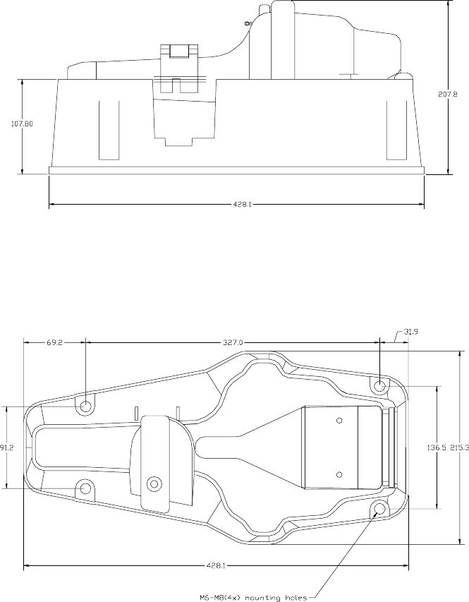
1.4 FB4/FBH4
Dimensions: Height : 42cm
Width : 21cm
Depth : 20cm (including beacon)
Weight : app. 1.6 kg / app. 2.9kg
Material : LURAN S
Hydrostatick release : Hammar H20

18.04.00 JOTRON electronics a.s 2-1
2.
Description
2.1 System description
The COSPAS/SARSAT system was introduced in 1982 as a worldwide search and rescue
system with the help of satellites covering the earth’s surface. Since the introduction of the
system more than 3000 people have been rescued by the COSPAS/SARSAT system.
Currently the system consists of 6 different satellites in a polar orbit constellation, these satellites
cover the entire earth’s surface and receive the emergency signal from the 406 MHz transmitter
within the Tron40S, more polar orbit satellites will be available in the future, giving a faster
location and rescue time.
In addition there is currently 1 geostationary satellite which is equipped with a 406 MHz
transponder, this satellite is not able to locate the Tron40S but will give an early warning to the
rescue forces, minimizing the time from an emergency occurs until the rescue forces are at the
site.
The COSPAS/SARSAT organization will launch more geostationary satellites that cover the
earth’s surface (except polar areas) in the near future (1995-2000).
Each emergency beacon in the system is programmed with its own unique code, therefore it is
vital that the ships data given to the dealer you obtained your Tron40S from, is correct. It is also
important that the beacon is registered in the database for each country. This database is
normally located in the same country that the ship is registered.
2.2 Signal detection
When the Tron40S is activated (manually or automatically) it transmits on the frequencies 121.5
MHz and 406.025 MHz. An analog signal is emitted on 121.5 MHz and a digital signal is
transmitted on 406.025 MHz.
After the Tron40S is activated, the next passing satellite will detect the transmitted signal and
relay it to an antenna at a ground station, called a LUT.
For the 121.5 MHz signal the satellite must be within line of sight of the Tron40S and a ground
station. The ground station or LUT has a 2500 km satellite reception radius centered at the LUT.
In areas without LUT coverage (mostly southern hemisphere), signals from the 121.5 MHz
transmitter will not be detected. However, this is not the case with the 406 MHz transmitter as
the satellites have a memory unit which stores the signals for relay to the next available LUT
giving it a truly global coverage.
Once the signal is received by the LUT, it is processed for location and sent to a Mission Control
Center (MCC). The MCC sorts the alert data according to geographic search and rescue regions
and distributes the information to the appropriate Rescue Coordination Center (RCC), or if
outside the national search and rescue area, to the appropriate MCC that covers the area that the
distress signal was detected. The RCC in turn takes the necessary action to initiate search and
rescue activities.
18.04.00 JOTRON electronics a.s 2-2
2.3 Distress Location Determination
The location of the distress signal is determined by taking measurements of the Doppler shift in
the beacon signal frequency received by the satellite as it approaches and then passes by the
Tron40S. The actual frequency is heard at the time of closest approach (TCA). Knowing the
position of the satellite and using the received Doppler signal information, it is possible to
determine the location of the Tron40S from the satellite at the TCA. At the LUT, actually two
positions are calculated. One is the actual position (A) and the other is the mirror image (B)
position. A second satellite pass confirms the correct location (A). With the 406 system the real
solution can be determined on the first pass with a reliability of nearly 90% and down to an
accuracy of less than 5 km (3.1 miles).
2.4 Tron 40S
Tron40S is a float free emergency beacon intended for use with the COSPAS-SARSAT
satellite system. Tron40S transmits on the frequencies 406.025 MHz and 121.5 MHz.
Tron 40S can be activated automatically or manually.
For automatic activation, put the beacon in the upright position into the water, and the
transmission starts when the sea water completes the circuit between the two external
electrodes (sea water contacts).
When the beacon is mounted in the automatic release mechanism, there is a safety switch in
the battery compartment that disables the seawater contacts.
If submerged in water the hydrostatic release mechanism will release the beacon at a depth of
2-4 meters. The transmission will start when the circuit between the seawater contacts are
closed and the beacon is out of the bracket.
Tron 40S is manually activated with the main switch, and is then independent of seawater
contacts.
Tron 40S may easily be released from the mounting bracket manually.

18.04.00 JOTRON electronics a.s 3-1
3.
General description
Tron 40S may be split into the following main parts:
1. Electronic unit with antenna
2. Battery unit
3. Equator ring with gasket.
3.1 Electronic unit with antenna.
The electronic unit consists of two printed circuit boards which are mounted in the upper
housing. One is the main board and the other is the antenna board.
On top of the antenna board the Xenon flash and an indicator LED is placed.
The main switch is also located on the main board.
The housing is made of polycarbonate.
3.2 Battery unit.
The housing is made of polycarbonate. In the lower part of the housing there is one reed relay
which is activated by a magnet in the release mechanism. This is the safety switch which
prevent the seawater contacts to activate the beacon while placed in the release mechanism.
There is a brass weight which gives stability while floating.
The seawater contacts is also mounted in the battery unit, and is connected to the electronic
unit via the battery connector.
The batteries is mounted in with a plastic battery holder, and is also moulded with silicon.
3.3 Equator ring with gasket.
The two parts of the housing are held together by the equator ring, and is locked with a U-
shaped bolt of stainless steel and a split pin. Between the two halves of the housing there is a
gasket made of neoprene.

18.04.00 JOTRON electronics a.s 4-1
4.
Operating instructions.
4.1 Manual operation
Remove the beacon from the release mechanism.
Break the seal on the main switch and pull the locking pin. Push in the tab on the main switch,
and the switch will go to the Emergency (ON) position.
The red indicator lamp and the Xenon flash on top of the beacon will start operating,
indicating that the beacon is active.
NOTE!
The beacon performs a complete selftest before any emergency signals are transmitted. The
Transmitters will start after approx. 70 seconds.
The transmission can be stopped by turning the switch back to the READY position, and
replacing the locking pin. Make sure the battery compartment is dry, to prevent activation of
the seawater contacts.
4.2 Automatic operation.
When the beacon is removed from the release mechanism and placed into water it will
automatically activate due to the seawater contacts. Transmission will stop when the beacon is
lifted out of the water, and if necessary dried off.
When placed in the automatic release mechanism the seawater contacts is disabled.
When the mechanism is reaching a depth of 2-4 meters , the beacon will be released and
transmission will start automatically.
Note! There is a time delay of approx. 10 seconds of activation/deactivation with the
seawater contacts.
4.3 Testing Tron 40S
To perform the selftest the beacon has to be removed from the release mechanism.
Turn the switch to the «TEST» position. The red indicator will start flashing for approx. 15
sec. This is to allow the internal OCXO (Oven Controlled Reference Oscillator) to warm
up.
Then the output power of both transmitters are checked, the battery voltage and the PLL of the
406 transmitter.
A complete message on the 406 frequency is transmitted, with inverted frame sync.
If all tests are passed there will be one flash in the Xenon bulb, and the red indicator light will
turn on and stay on until the switch is released.
18.04.00 JOTRON electronics a.s 4-2
A successful test will then consist of a series of rapid flashes in the test indicator , followed by
one Xenon flash and continuos light in the test indicator.
Any other behaviour indicates a fault in the beacon.
4.4 Error messages
If the selftest detects a fault in the beacon on or more of the following indications are shown :
1. Flashing LED for 15 sec. followed by one (1) flash , no Xenon flash :
Low power on 406 MHz transmitter
2. Flashing LED for 15 sec. followed by two (2) flashes, no Xenon flash :
Low battery voltage.
3. Flashing LED for 15 sec. followed by three (3) flashes , no Xenon flash :
Low power on 121.5 MHz transmitter
4. Flashing LED for 15 sec. followed by four (4) flash , no Xenon flash :
PLL on 406 transmitter out of lock.
5. Five (5) flashes , no Xenon flash:
Beacon not programmed or programming not complete.

18.04.00 JOTRON electronics a.s 5-1
5.
Change of battery
The lower part of the beacon of the housing is replaced with a new one.
1. Remove split pin and pull the U-shaped bolt from the equator ring.
2. Remove the equator belt by pressing it out from the housing.
3. Separate the two parts of the housing.
4. Unplug the battery connector.
5. Check that the new battery is marked with date of expiration.
6. Place the new gasket on the battery housing.
7. Connect the battery connector.
8. Replace the upper part, taking care that the gasket is correctly fitted and taking note of the
orientation marks on the two housings.
9. Replace the equator ring, U-shaped bolt and split pin.
10.
Perform a Selftest.

18.04.00 JOTRON electronics a.s 6-1
6.
Technical description
6.1 Main board
The main board can be divided into the following groups :
1. 406 MHz section
2. 121.5MHz section
3. Microcontroller section
4. Powersupply section
5. Antenna section
6.2 406 MHz section.
The 406 transmitter consists of VCO (Q101), buffer amplifier (Q102) and power amplifier
(Q103). The output power is 5W. The supply voltage is regulated and switched in the power
supply section.
The output frequency is controlled by a PLL circuit (IC203), prescaler (IC204) and reference
oscillator (IC205).
Modulation is applied to the reference signal by pulling the reference signals phase.
6.3 121.5 MHz section.
The 121.5MHz transmitter is Xtal controlled. The output power is approx. 200mW PEP. The
output power is controlled by IC301 which senses the current in the output stage. The output
signal is fed into the antenna via the matching network consisting of L308 and L307. 406
MHz signal is fed directly to the same antenna via pin diode D809. This diode is reverse
biased when transmitting on 121.5MHz., by rectifying and inverting the modulation
signal(D306).
6.4 Microcontroller section
This section consists of a microcontroller (IC401), EEPROM (IC402) for storing of
programming data, a DIL switch, and an I/R interface for programming.
The DIL switch has the following function :
1. VHF modulation on/off
2. UHF repetition rate normal/fast
3. UHF on/off
4. VHF on/off
18.04.00 JOTRON electronics a.s 6-2
6.5 Power supply section
The main switch controls Q503 via reed relays Rel501, Rel502 and Rel503. The seawater
circuit (IC503) is supplied from a separate reed in the battery compartment, to prevent it from
working when placed in the bracket.
IC502 is the 5V main voltage regulator for the microcontroller. It is also reference voltage for
the 406 supply witch/regulator.
The circuit to prevent continuos transmission on 406MHz consist of R512, C503, IC501B and
Q504. If the transmission length exceeds a few seconds, Q504 is biased and the fuse F501 will
be blown.
6.6 Antenna section
The antenna board is the actual antenna. It behaves as a quarter wave on 406 MHz. It is
matched to 121.5 MHz as described in 121.5 MHz section.
The high voltage converter to the Xenon flash is also located on the antenna board. The
Xenon bulb and test indicator (LED) is placed at the upper end of the antenna board.
18.04.00 JOTRON electronics a.s 7-1
7.
Automatic Release Mechanism
7.1 Float Free Bracket FB4/FBH4
When the Tron40S is mounted in the FB4/FBH4 release mechanism, it operates as a float free
automatic unit.
Therefore it is important that the bracket is mounted in a place where there are no obstructions
that can endanger the automatic release of the beacon.
The location where the bracket is mounted should be as high as possible on the vessel,
protected from environmental conditions such as direct sea spray, chemicals, oil, exhaust and
vibrations. The location must also be easily accessible for testing and maintenance.
7.2 Mounting the FB4/FBH4
Bolt the unit to the vessel using the mounting holes.
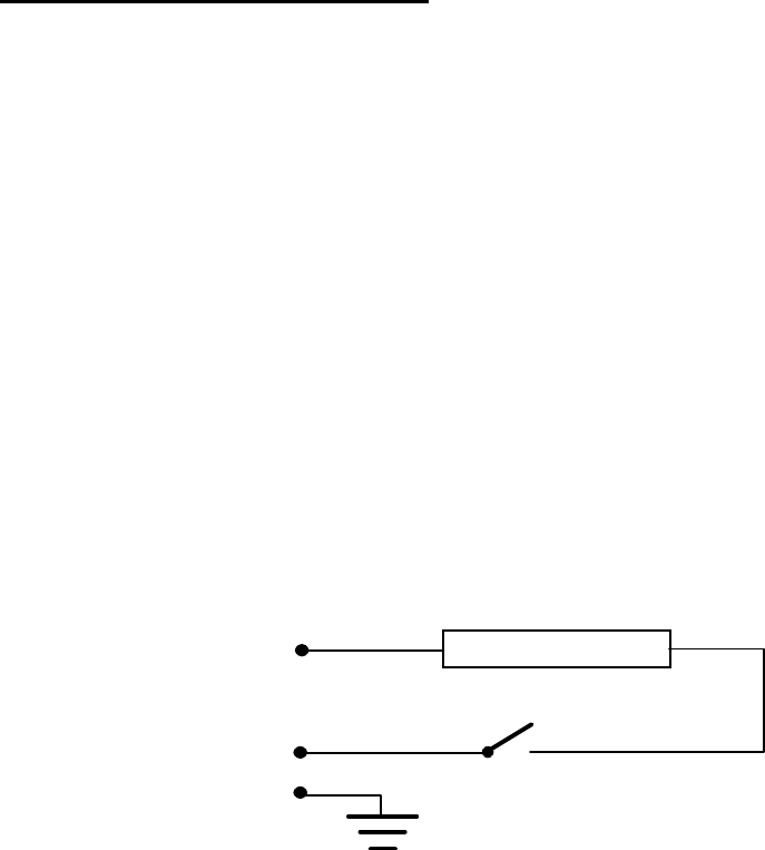
The Float Free Bracket FBH4 must be connected to the fixed installation (230V AC, 10A)
through the termostate connection box according to the connection diagram.
CONNECTION DIAGRAM
230 V AC, 10 A
HEATING ELEMENT
Thermostat
7.3 Mounting of Tron40S in the FB4/FBH4
Place the lower part of Tron40S on the grip in the bracket. Then push the beacon into the
bracket and fold the clamp over the upper part. Place the retaining rod into the corresponding
holes in the clamp and the plastic bolt.
Replace the locking pin.
7.4 Replacement and mounting of the Hydrostatic Release Mechanism
• While holding the Tron 40S in its place, pull out the locking pin on clamp on the top of the
bracket.
• Fold the clamp away.
• Lift the Tron 40S out of the bracket.
• Now the H20 unit is accessible. Unscrew the plastic bolt and remove the unit.
• Replace the old unit with a new one . Screw the new plastic bolt on. Make sure the distance
piece is in place on the plastic bolt.
• Mount the Tron 40S as described earlier.

18.04.00 JOTRON electronics a.s 8-1
8.
Drawings
Main Board :
Circuit diagrams: E-92716-1
E-92716-2
E-92716-3
E-92716-4
E-92716-5
Component Layout KP-92716-1
KP-92716-2
Antenna Board :
Circuit diagrams: E-92718
Component layout KP-92718-1
KP-92718-2
Battery unit: E-97780
Outline drawing: Tron40S in FB4
18.04.00 JOTRON electronics a.s 8-2
Outline drawings FB4/FBH4
18.04.00 JOTRON electronics a.s 8-3