Jotron Electronics A S TRON40S (See comments below) User Manual Technical Handbook
Jotron Electronics A/S (See comments below) Technical Handbook
UserManual.wiki
>
Jotron Electronics A S
>
TRON40S User Manual
>
Technical Handbook
Contents
1.
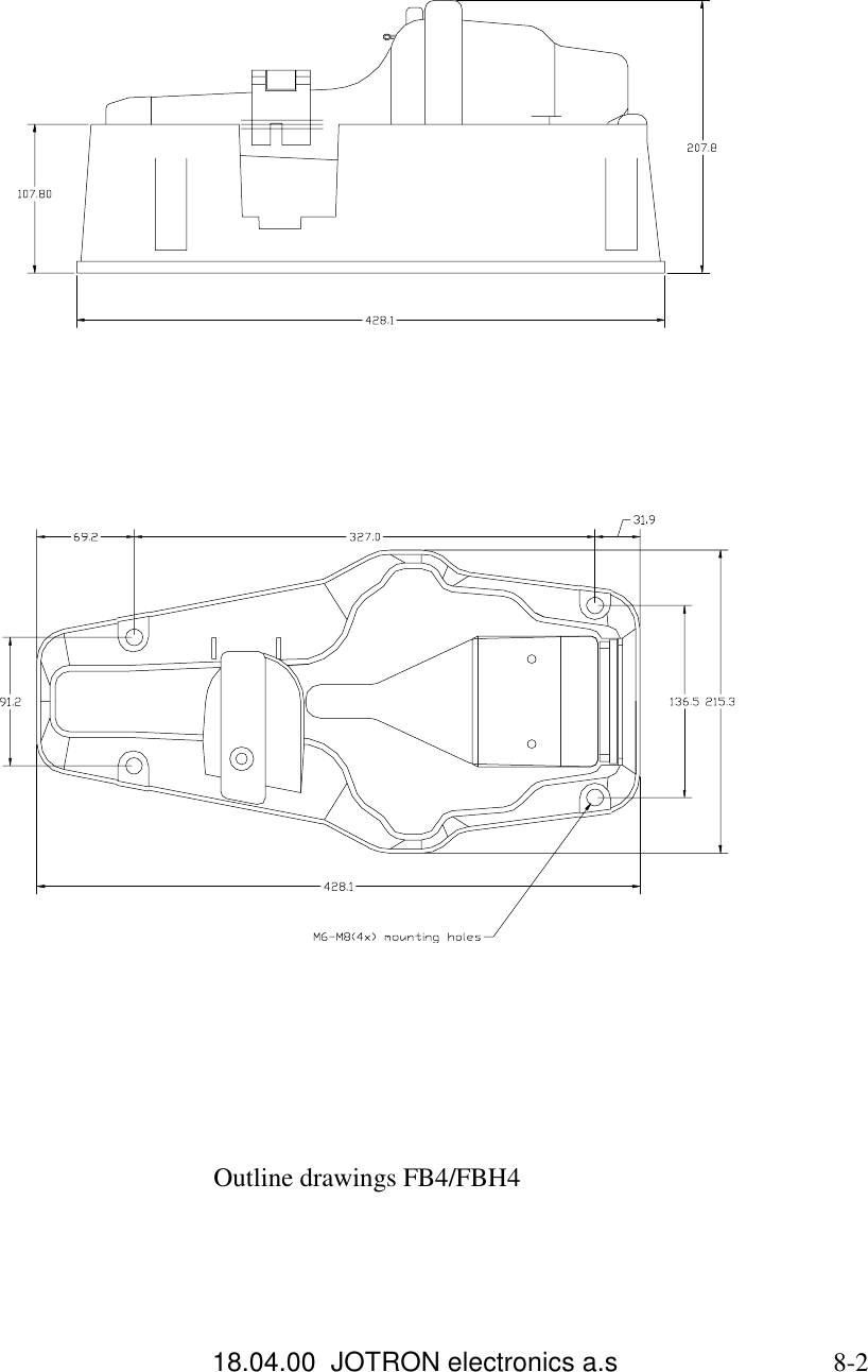
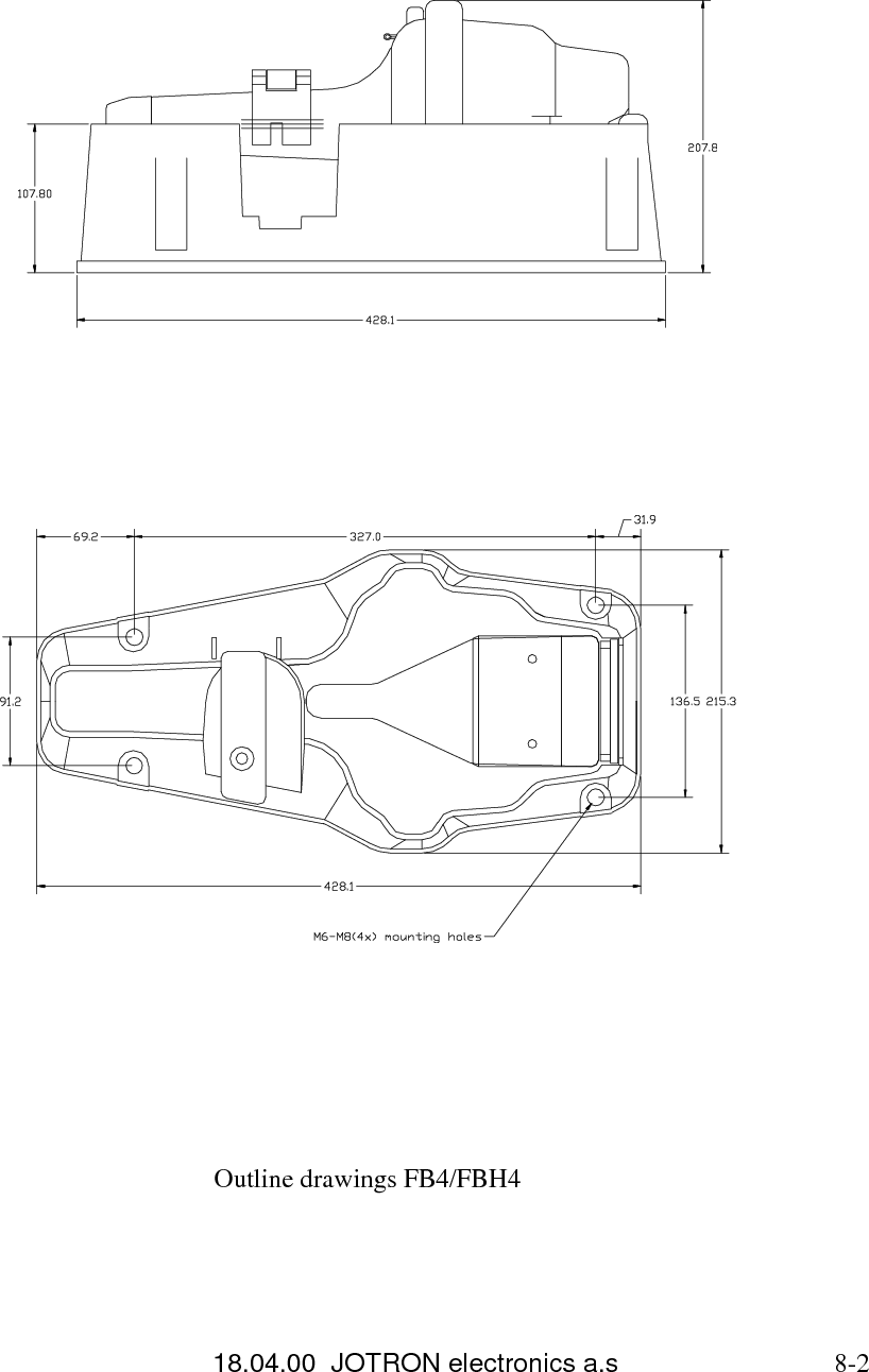
Technical Handbook
2.
Operators Manual
Technical Handbook
Navigation menu
Upload a User Manual
Namespaces
Wiki Guide
HTML
PDF
Info
Views
User Manual
Discussion / Help
Navigation