Joysway Hobby J3C0001 2.4GHz Pistol Grip Radio Control System User Manual J3C91
Joysway Hobby (HK) Limited 2.4GHz Pistol Grip Radio Control System J3C91
User manual
CAUTION
2.4G Binding
To work your R/C with your models correctly and safely,read this manual carefully and keep it in a safe
way as a reference introduction in the future
Warning:
1.This product is only equipped for radio controlled models.
2.The usage of this product should be approved by local relevant law or regulations.
3.we will not be responsible for the damages caused by unauthorized modification, adjustment or
replacement of parts of this product.
4.The manual maybe altered without prior notice. Please contact us if you have any corrections or
clarifications that should be made in the manual.
Before starting the transmitter, make sure the transmitter batteries are well loaded. The voltage of
transmitter batteries is never lower than 4.5V. And please check and confirm that the servos are all
well and properly connected.
Keep the radio system away from moist, high temperature and strong shake. Do not clean the product
with solvent.
The antenna does not touch anything else when power switch is turned on. Do not leave this product
and its accessories within the reach of small children.
Please use this product according to your local relevant law or regulation, we are not responsible for
any incidents or damages.
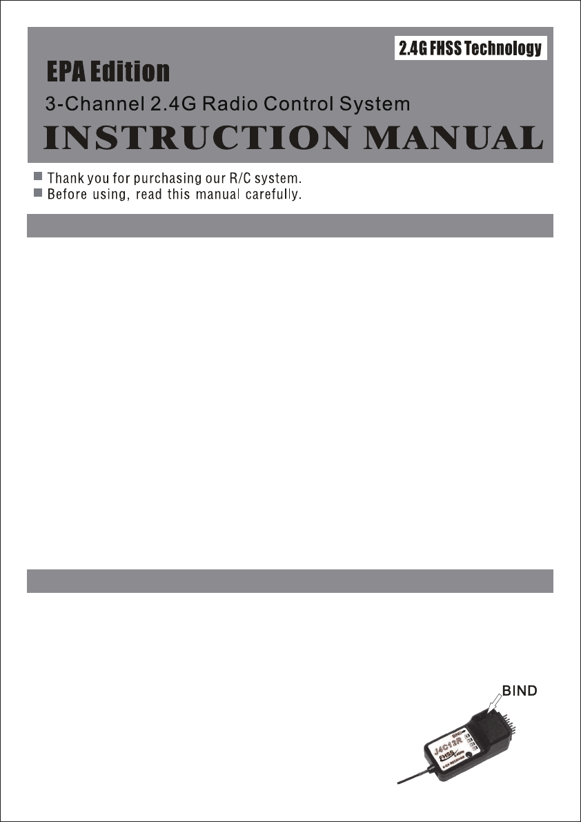
The Binding processing
Turn on the transmitter, then connect the power of receiver, pressing the receiver “BIND” button till the
light turn on GREEN which means the binding is successful. After that, it’s unnecessary to bind again.
Caution:
make sure the RX and TX is within one meter, and around 10 meters no similar devices.
If the light flashing, showing the binding failure. Please do again as above indication.
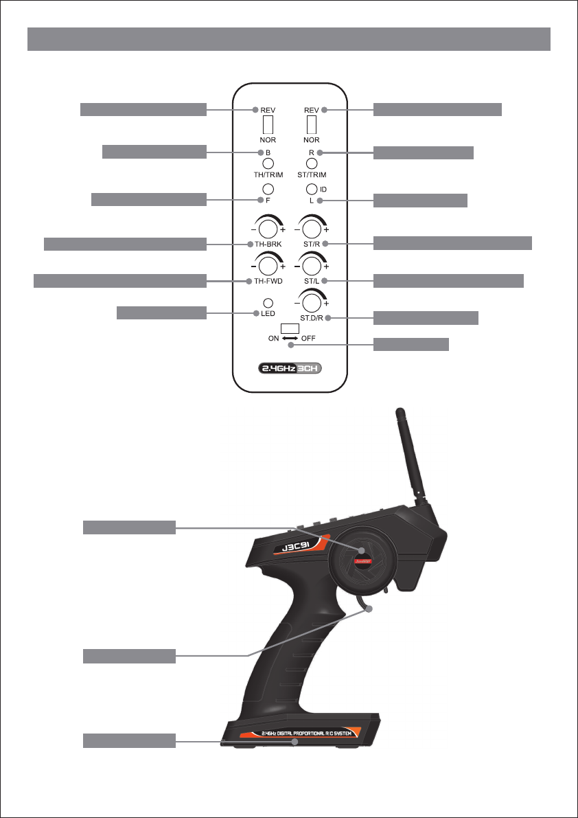
Transmitter introduction
Steering wheel
Throttle Trigger
Battery Box
Steering reverse switch
Throttle reverse switch
Steering trim-right
Steering trim-left
Throttle trim-brake
Throttle trim-forward
Steering traveling angle-right
Steering traveling angle-left
Throttle traveling value-brake
Throttle traveling value-forward
Steering dual rates
Power indicator
Power switch
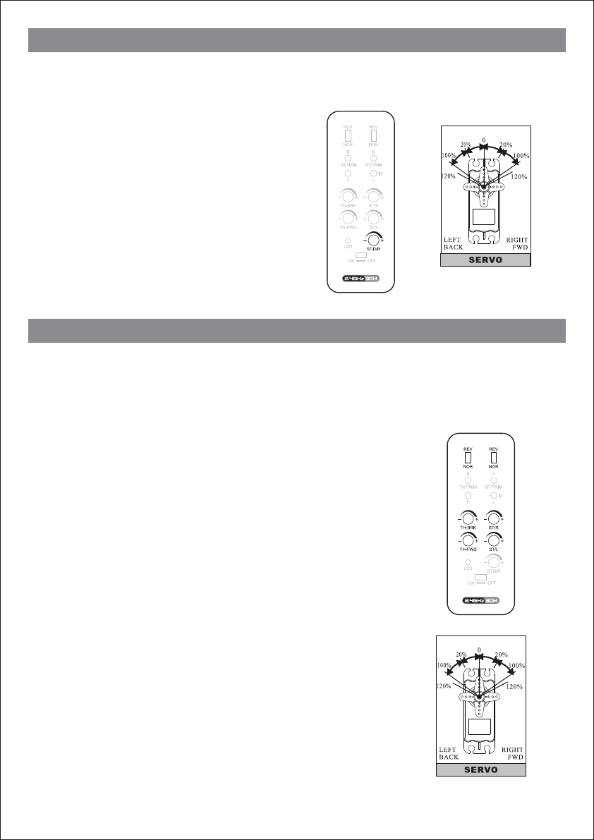
Steering Dual Rates Setup
EPA Adjustment
Function
Using this function to adjust servo travel. The default is 100%, adjusting value range: 20%-120%
Setting
Rotate the “ST.D/R” knob to the left end point means
steering servo of value reach minimum value.
Rotate the “ST.D/R” knob to the right end point means
steering servo of value reach maximum value.
Function
Use this when performing left and right steering angle adjustments, throttle high side/brake side
operation amount adjustment during linkage. End Point Adjustment (EPA)
adjusting value range: 0%-100%
Setting
1.Steering (right side) adjustment
Rotate “ST/R” knob to the left end point means minimum value 0%,
right end point means maximum value 100%.
2.Steering (left side) adjustment
Rotate “ST/L” knob to the left end point means minimum value 0%,
right end point means maximum value 100%.
3.Throttle (brake side) adjustment
Rotate “TH-BRK” knob to the left end point means minimum value 0%,
right end point means maximum value 100%.
4.Throttle (forward side) adjustment
Rotate “TH-FWD” knob to the left end point means minimum value 0%,
right end point means maximum value 100%.
CAUTION:
When adjusting this function, make sure the direction is in agreement
with the car or boat direction, you can adjust by the “REV-NOR” button.
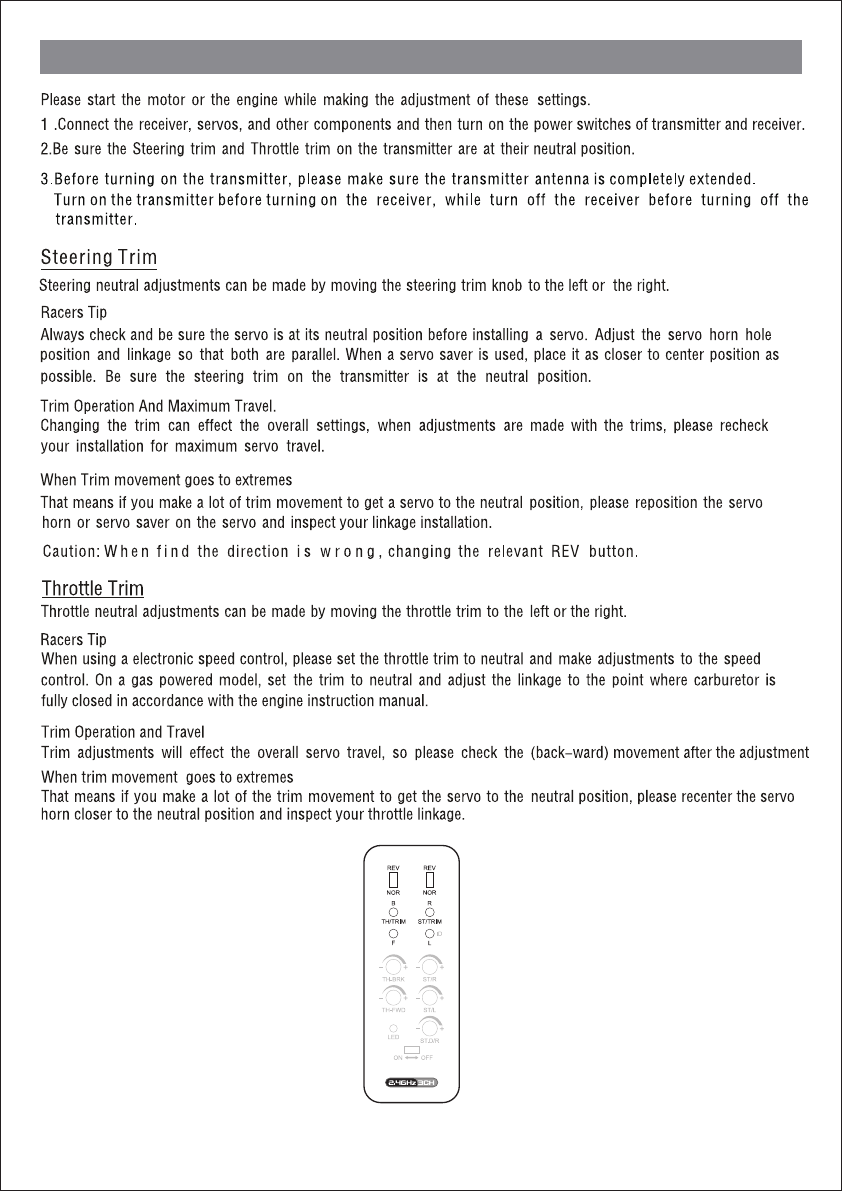
Trim Adjustment
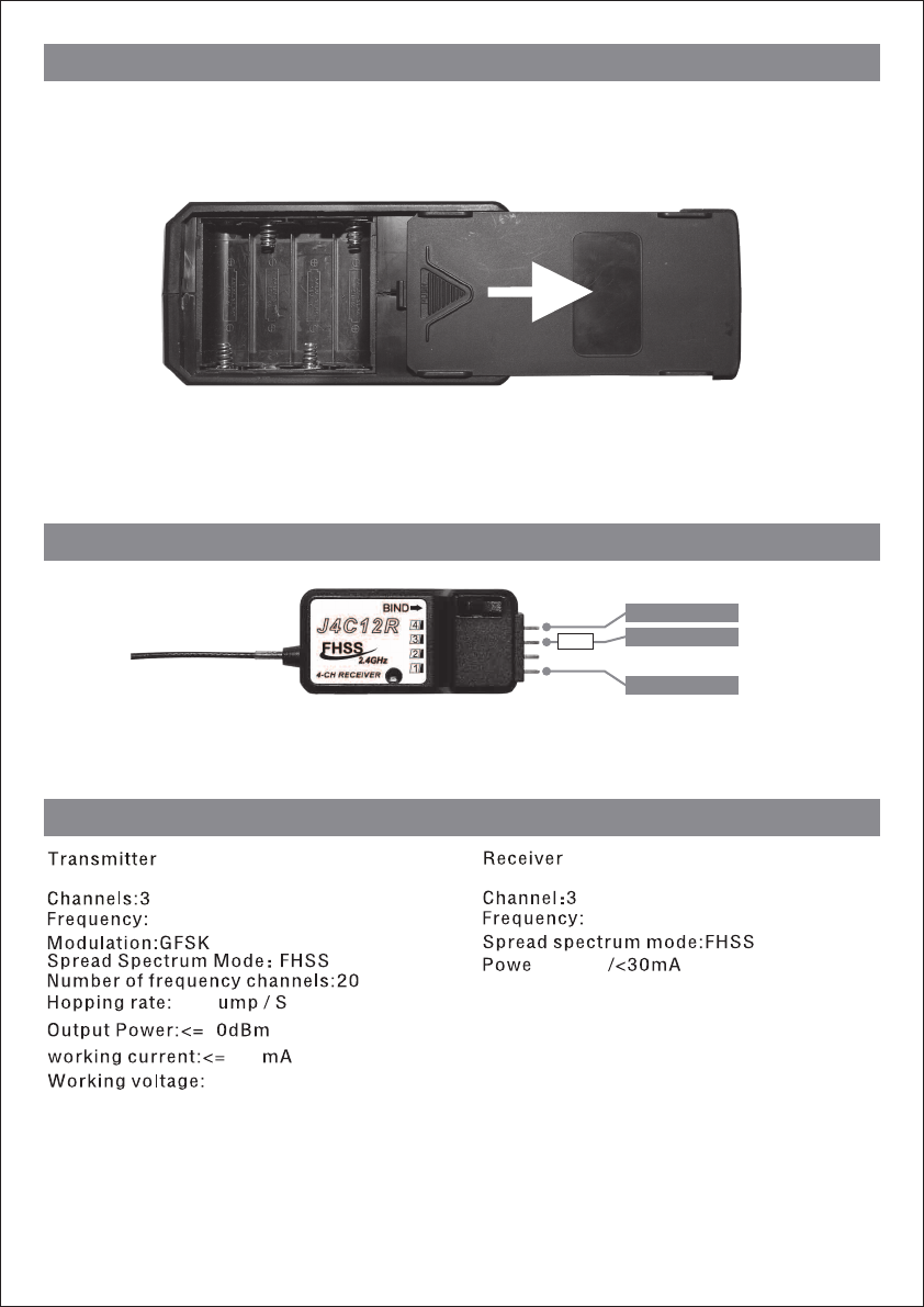
Transmitter Batteries Installation
Receiver Connection Diagram
The transmitter requires 4 “AA” batteries. Do not mix old and new cells. To install the batteries, slide
open the battery door on the bottom of the Transmitter. Install the batteries in the holder as shown in
the diagram (see marks molded inside the case). Make sure to note the proper polarities on each cell.
Close the battery door.
IMPORTANT: Do not operate an R/C model with weak batteries as it could result in reduced range
and/or possible loss of control !
BATT.(5V)
SERVO2(TH.)
SERVO1(ST.)
ESC
Technology Data
2405MHz-2450MHz
100 J
1
6V
2405MHz-2450MHz
:4.8V-6V
180

FCC Statement
This equipment has been tested and found to comply with the limits for a Class B digital device,
pursuant to part 15 of the FCC rules. These limits are designed to provide reasonable protection
against harmful interference in a residential installation. This equipment generates, uses and can
radiate radio frequency energy and, if not installed and used in accordance with the instructions,
may cause harmful interference to radio communications. However, there is no guarantee that
interference will not occur in a particular installation. If this equipment does cause harmful interference
to radio or television reception, which can be determined by turning the equipment off and on, the user
is encouraged to try to correct the interference by one or more of the following measures:
-Reorient or relocate the receiving antenna.
-Increase the separation between the equipment and receiver.
-Connect the equipment into an outlet on a circuit different from that to which the receiver is connected.
-Consult the dealer or an experienced radio/TV technician for help.
To assure continued compliance, any changes or modifications not expressly approved by the party
responsible for compliance could void the user’s authority to operate this equipment. (Example- use
only shielded interface cables when connecting to computer or peripheral devices).
This equipment complies with Part 15 of FCC RF Rules. Operation is subject to the following two
conditions:
1) This device may not cause interference and
2) This device must accept any interference, including interference that may cause undesired
operation of the device.
Caution:
Any changes or modifications not expressly approved by the party responsible for compliance could
void the user's authority to operate this equipment.
EU Declaration of Conformity
Hereby, Joysway Hobby (HK) Limited, declares that this device is in compliance with the essential
requirements and other relevant provisions of Directive 1999/5/EC.