Juniper Networks 632 802.11abgn outdoor AP User Manual Trapeze Manual s and reference
Juniper Networks, Inc. 802.11abgn outdoor AP Trapeze Manual s and reference
Contents
- 1. User Manual
- 2. Campus Connectivity MP Quick Start Guide Rev. A
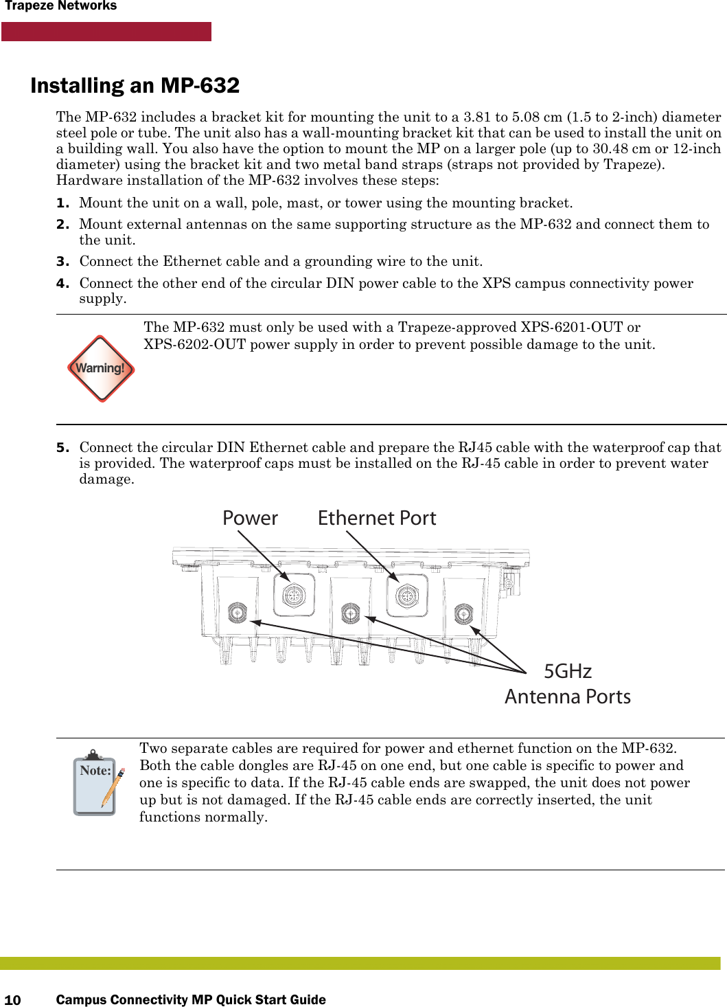
- 3. Campus Connectivity MP Quick Start Guide Rev B
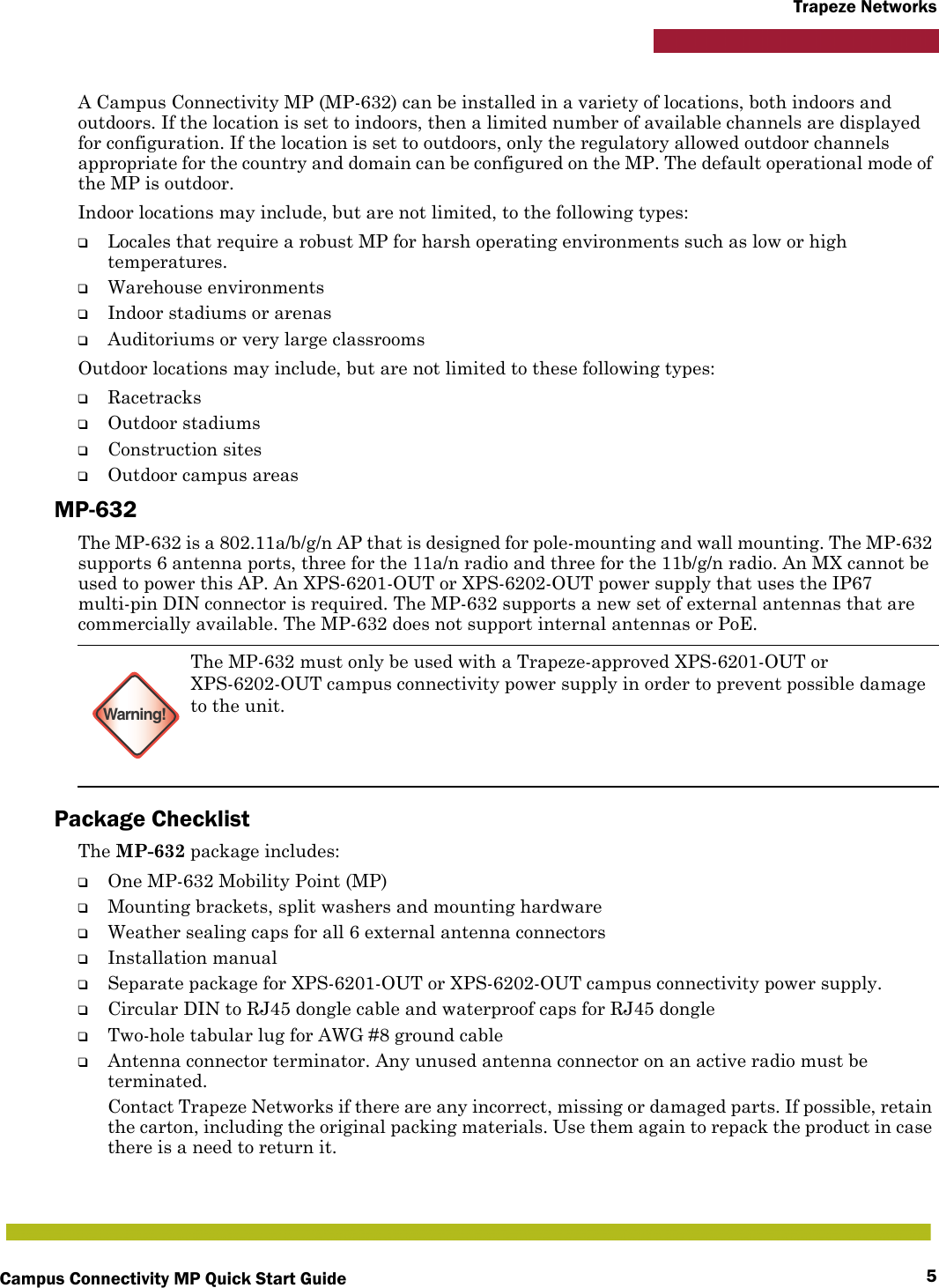
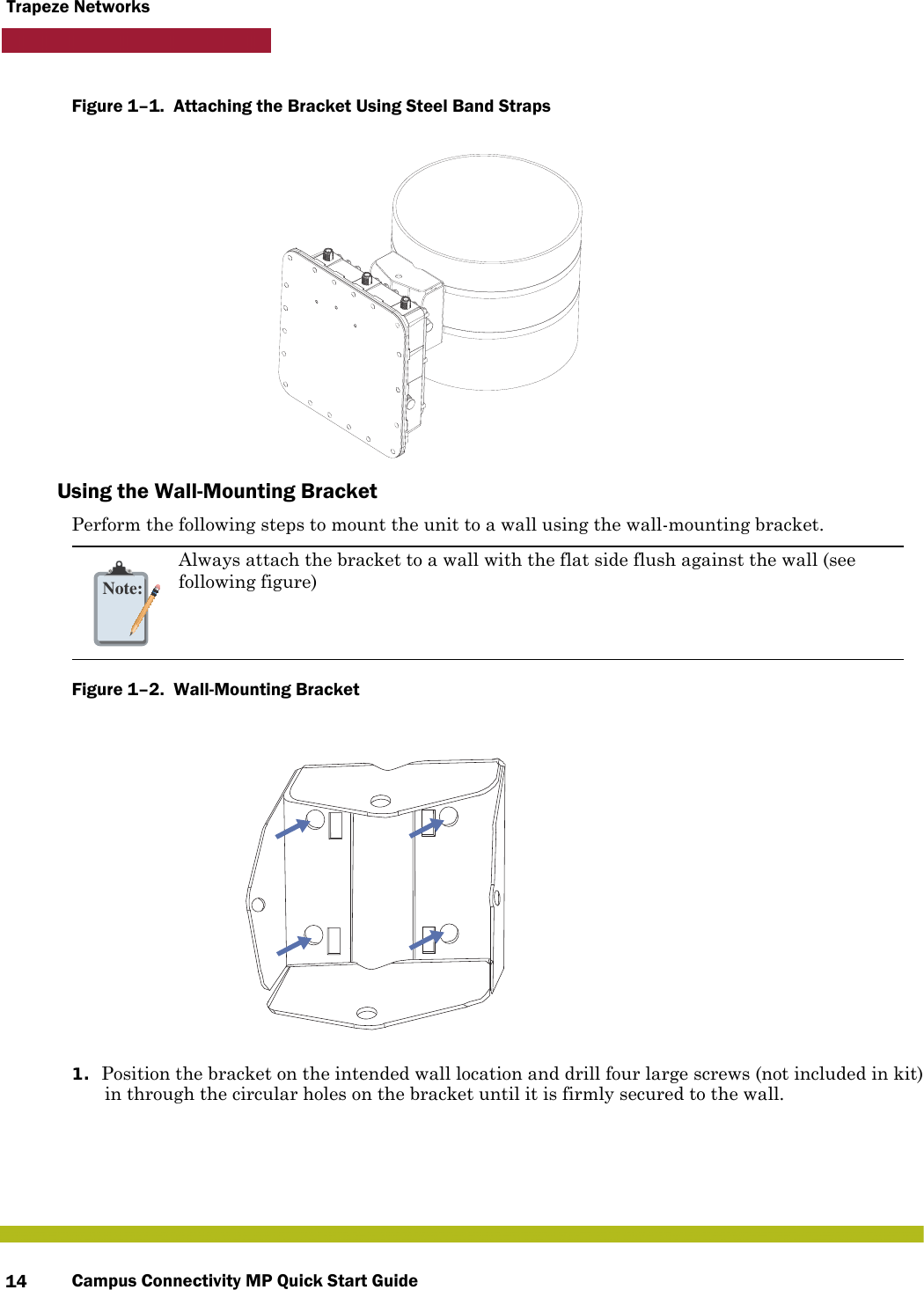
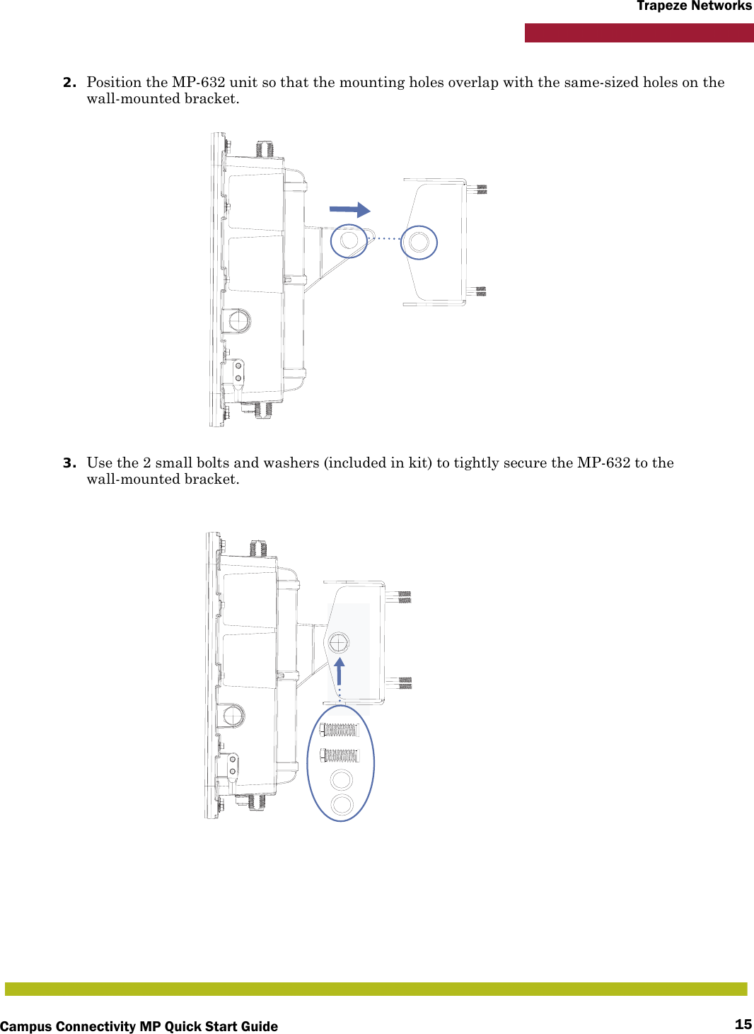
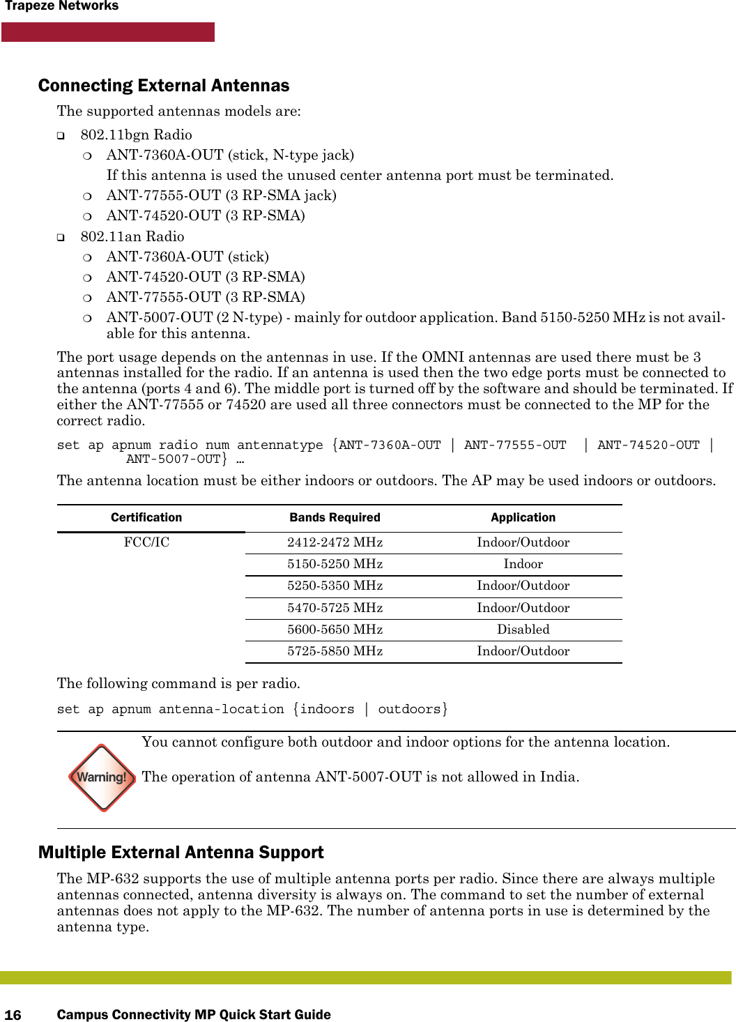
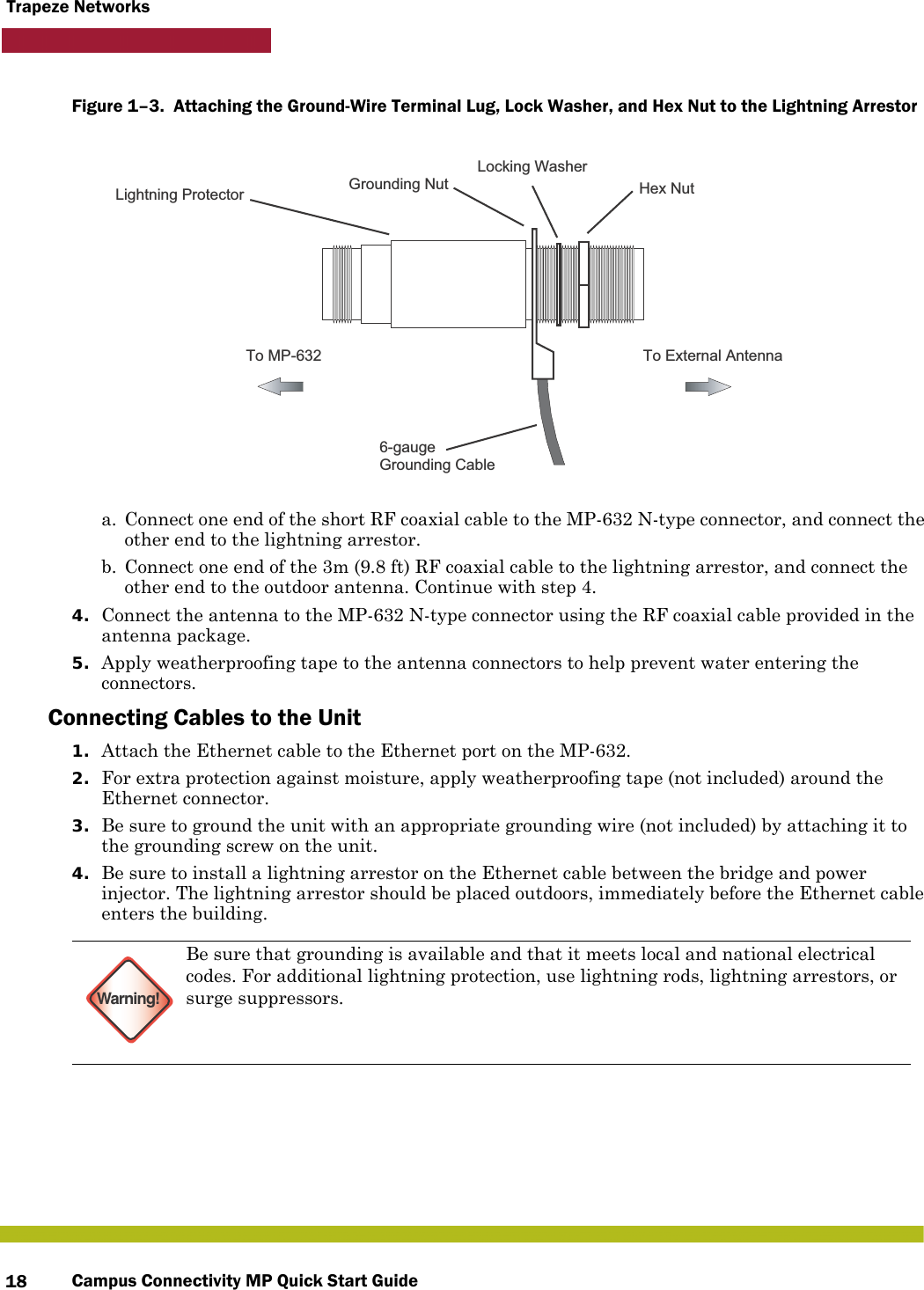
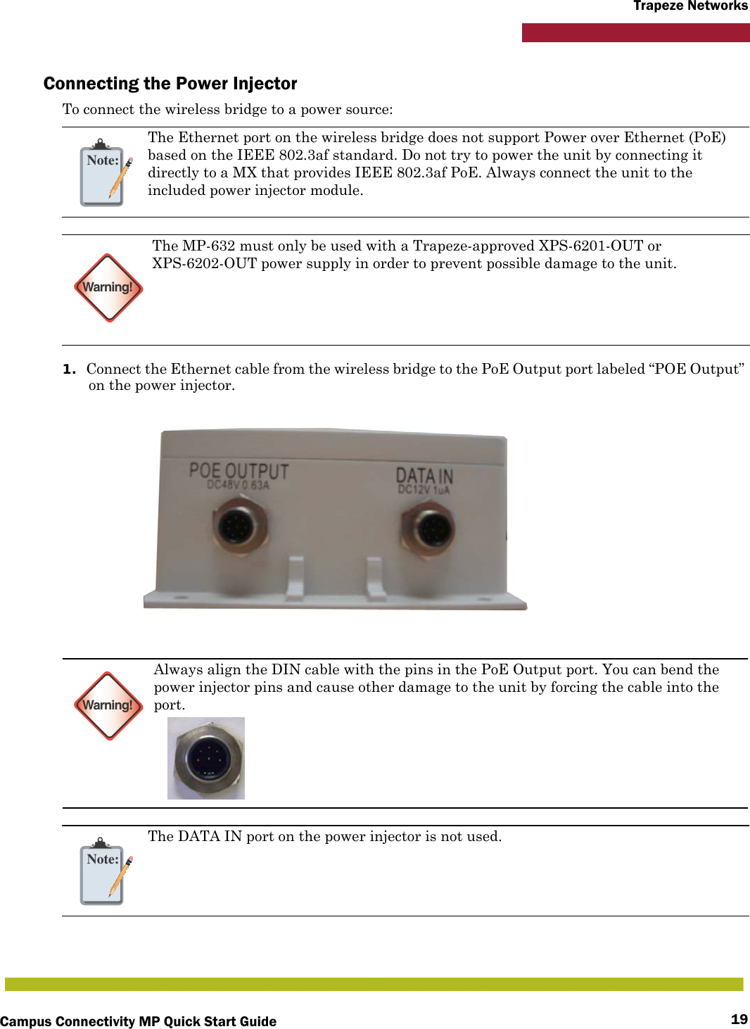
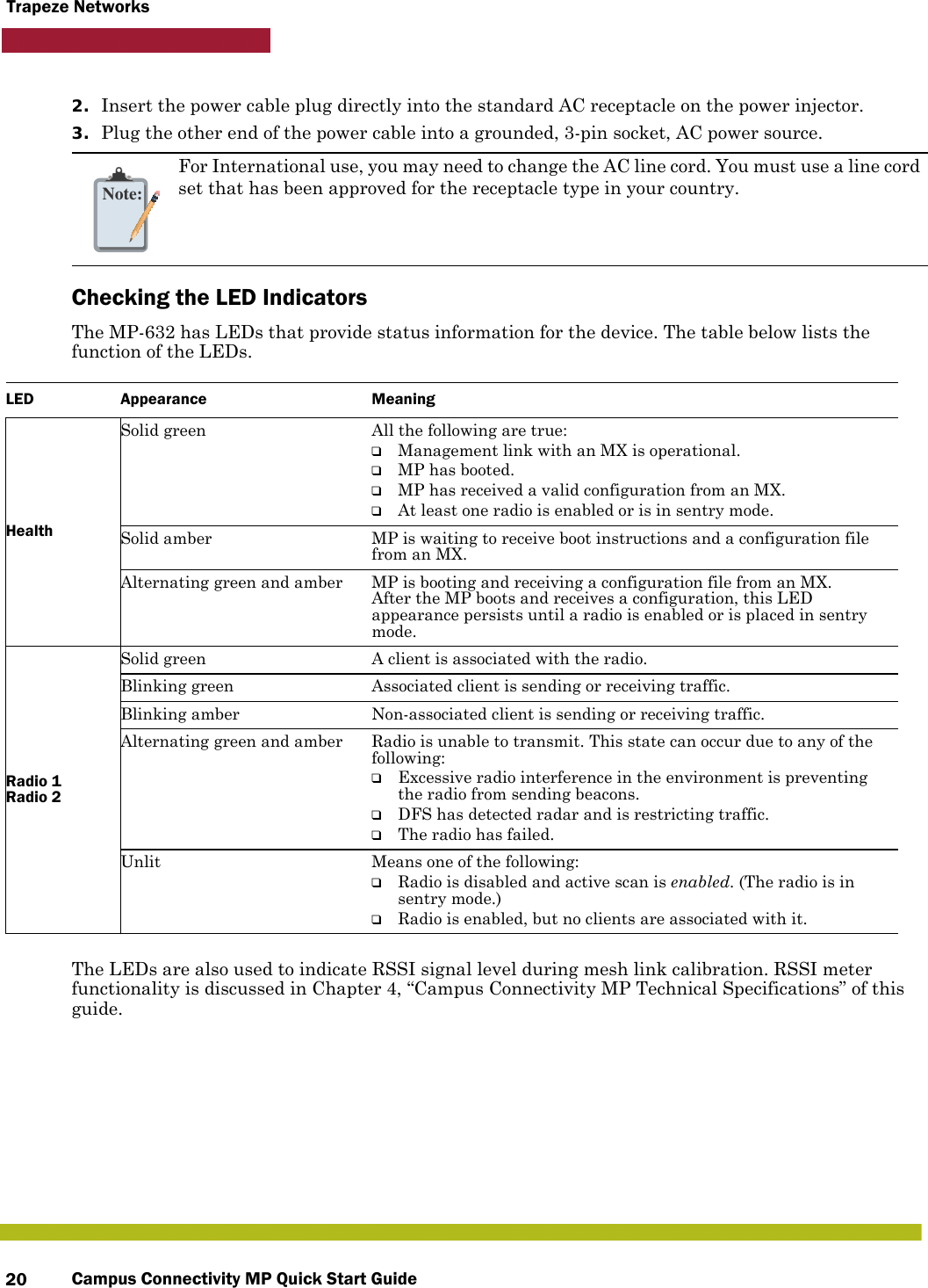
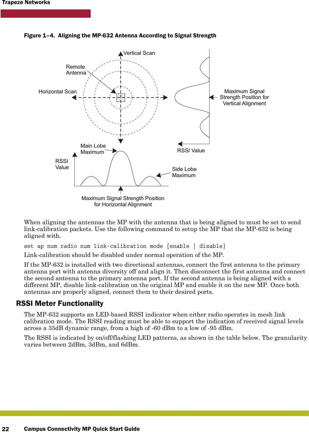
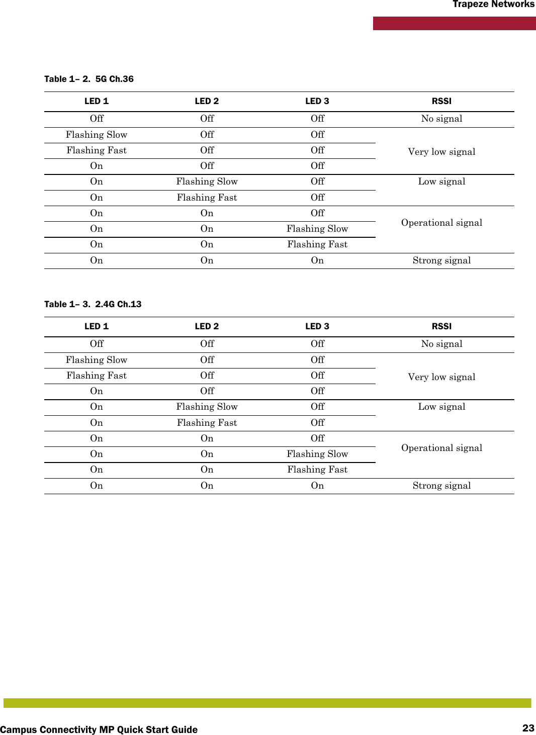
Campus Connectivity MP Quick Start Guide Rev B
![Campus Connectivity MP Quick Start Guide8Trapeze NetworksRadio Frequency ExposureFederal Communications Commission (FCC) Docket 96-8 for Spread Spectrum Transmitters specifies a safety standard for human exposure to radio frequency electromagnetic energy emitted by FCC-certified equipment. When used with the proper antennas (shipped in the product), Trapeze Networks MP access point products meet the uncontrolled environmental limits found in OET-65 and ANSI C95.1-1991. Proper installation of the MP access point according to the instructions in this manual will result in user exposure that is below the FCC recommended limits.!CautionFCC Notice: For indoor operations:Devices will not permit operations on channels 120-132 for 11a and 11n/a which overlap the 5600 - 5650 MHz band.For outdoor operations: In order to meet new FCC, NTIA, FAA and industry restrictions to resolve interference to Terminal Doppler Weather Radar (TDWR) systems used at airports, any outdoor device installed within 35 km of a TDWR location must be separated by at least 30 MHz (center-to-center) from TDWR operating frequency (as shown in the table below). Channels 120-132 and 5600-5650 MHz band are disabled on Trapeze outdoor products.Trapeze recommends that all operators and installers register the location information of the UNII devices operating outdoors in the 5470 – 5725 MHz band within 35 km of any TDWR location at the WISPA sponsored database (see http://www.spectrumbridge.com/udia/home.aspx). This database may be used by government agencies in order to expedite resolution of any interference to TDWRs.Procedures on how to register the devices in the industry-sponsored database with the appropriate information regarding the location and operation of the device and installer information can be found on the database.Table 1– 1. TDWR Location InformationState City Longitute Latitude FrequencyTerrain Elevation (MSL) [ft]Antenna Height Above Terrain [ft]AZ Phoenix W 112 09 46 N 33 25 14 5610 MHz 1024 64CO Denver W 104 31 35 N 39 43 39 5615 MHz 5643 64FL Ft. Lauderdale W 080 20 39 N 26 08 36 5645 MHz 7 113FL Miami W 080 29 28 N 25 45 27 5605 MHz 10 113FL Orlando W 081 19 33 N 28 20 37 5640 MHz 72 97FL Tampa W 082 31 04 N 27 51 35 5620 MHz 14 80FL West Palm Beach W 080 16 23 N 26 41 17 5615 MHz 20 113GA Atlanta W 084 15 44 N 33 38 48 5615 MHz 962 113IL McCook W 087 51 31 N 41 47 50 5615 MHz 646 97](https://usermanual.wiki/Juniper-Networks/632.Campus-Connectivity-MP-Quick-Start-Guide-Rev-B/User-Guide-1365671-Page-8.png)
![Campus Connectivity MP Quick Start Guide 9Trapeze NetworksIL Crestwood W 087 43 47 N 41 39 05 5645 MHz 663 113IN Indianapolis W 086 29 08 N 39 38 14 5605 MHz 751 97KS Wichita W 097 26 13 N 37 30 26 5603 MHz 1270 80KY Covington CincinnatiW 084 34 48 N 38 553 53 5601 MHz 942 97KY Louisville W 085 36 38 N 38 02 45 5646 MHz 617 113LA New Orleans W 090 24 11 N 30 01 18 5645 MHz 2 97MA Boston W 070 56 01 N 42 09 30 5610 MHz 151 113MD Brandywine W 076 50 42 N 38 41 43 5635 MHz 233 113MD Benfield W 076 37 48 N 39 05 23 5645 MHz 184 113MD Clinton W 076 57 43 N 38 45 32 5615 MHz 249 97MI Detroit W 083 30 54 N 42 06 40 5615 MHz 656 113MN Minneapolis W 092 55 58 N 44 52 17 5610 MHz 1040 80MO Kansas City W 094 44 31 N 39 29 55 5605 MHz 1040 64MO Saint Louis W 090 29 21 N 38 48 20 5610 MHz 551 97MS Desoto County W 089 59 33 N 34 53 45 5610 MHz 371 113NC Charlotte W 080 53 06 N 35 20 14 5608 MHz 757 113NC Raleigh Durham W 078 41 50 N 36 00 07 5647 MHz 400 113NJ Woodbridge W 074 16 13 N 40 35 37 5620 MHz 19 113NJ Pennsauken W 075 04 12 N 39 56 57 5610 MHz 39 113NV Las Vegas W 115 00 26 N 36 08 37 5645 MHz 1995 64NY Floyd Bennett FieldW 073 52 49 N 40 35 20 5647 MHz 8 97OH Dayton W 084 07 23 N 40 01 19 5640 MHz 922 97OH Cleveland W 082 00 28 N 41 17 23 5645 MHz 817 113OH Columbus W 082 42 55 N 40 00 20 5605 MHz 1037 113OK Aero. Ctr TDWR #1W 097 37 31 N 35 24 19 5610 MHz 1285 80OK Aero. Ctr TDWR #2W 097 37 43 N 35 23 34 5620 MHz 1293 97OK Tulsa W 095 49 34 N 36 04 14 5605 MHz 712 113OK Oklahoma City W 097 30 36 N 35 16 34 5603 MHz 1195 64PA Hanover W 080 29 10 N 40 30 05 5615 MHz 1266 113PR San Juan W 066 10 46 N 18 28 26 5610 MHz 59 113TN Nashville W 086 39 42 N 35 58 47 5605 MHz 722 97TX Houston IntercontinentalW 095 34 01 N 30 03 54 5605 MHz 154 97TX Pearland W 095 14 30 N 29 30 59 5645 MHz 36 80Table 1– 1. TDWR Location InformationState City Longitute Latitude FrequencyTerrain Elevation (MSL) [ft]Antenna Height Above Terrain [ft]](https://usermanual.wiki/Juniper-Networks/632.Campus-Connectivity-MP-Quick-Start-Guide-Rev-B/User-Guide-1365671-Page-9.png)
![Campus Connectivity MP Quick Start Guide 25Trapeze NetworksCanadian Department of Communications Industry Canada Notice (Canada)This digital apparatus meets the requirements of Canadian Interference-Causing Equipment Regulation RSS-210.This Class B digital apparatus complies with Canadian ICES-003.Operation is subject to the following two conditions: 1. This device may not cause interference.2. This device must accept any interference, including interference that may cause undesired operation of the device. Cet appareil numérique de la classe B conforme á la norme NMB-003 du Canada.Country Code Statement: For product available in the USA/Canada market, only channel 1~11 can be operated. Selection of other channels is not possible.This device and its antenna(s) must not be co-located or operation in conjunction with any other antenna or transmitter.To reduce potential radio interference to other users, the antenna type and its gain should be so chosen that the equivalent isotropically radiated power (e.i.r.p) is not more than that permitted for successful communication.This device has been designed to operate with the antennas listed below, and having a maximum gain of [23.5] dB. Antennas not included in this list or having a gain greater than [23.5] dB are strictly prohibited for use with this device. The required antenna impedance is 50 ohms.The device could automatically discontinue transmission in case of absence of information to transmit, or operational failure. Note that this is not intended to prohibit transmission of control or signaling information or the use of repetitive codes where required by the technology.The device for the band 5150-5250 MHz is only for indoor usage to reduce potential for harmful interference to co-channel mobile satellite systems.The maximum antenna gain permitted (for devices in the band 5725-5825 MHz) to comply with the e.i.r.p. limits specified for point-to-point and non point-to-point operation as appropriate, as stated in section A9.2(3).The maximum antenna gain permitted (for devices in the bands 5250-5350 MHz and 5470-5725 MHz) to comply with the e.i.r.p. limit. High-power radars are allocated as primary users (meaning they have priority) of the bands 5250-5350 MHz and 5650-5850 MHz and these radars could cause interference and/or damage to LE-LAN devices.!CautionIC Radiation Exposure Statement: This equipment complies with IC RSS-102 radiation exposure limits set forth for an uncontrolled environment. This equipment should be installed and operated with minimum distance 20cm (about 8 inches) between the radiator & your body.](https://usermanual.wiki/Juniper-Networks/632.Campus-Connectivity-MP-Quick-Start-Guide-Rev-B/User-Guide-1365671-Page-25.png)