Juniper Networks SSG5 Secure Services Gateway 5 User Manual SSG5 HW
Juniper Networks Inc. Secure Services Gateway 5 SSG5 HW
UserManual.wiki
>
Juniper Networks
>
SSG5 User Manual
users manual
Navigation menu
Upload a User Manual
Namespaces
Wiki Guide
HTML
PDF
Info
Views
User Manual
Discussion / Help
Navigation
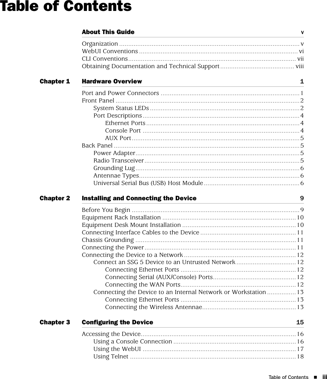
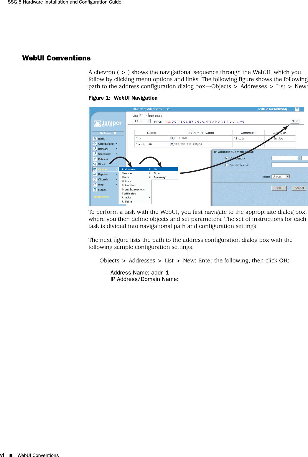
![CLI Conventions viiAbout This GuideIP/Netmask: (select), 10.2.2.5/32Zone: UntrustFigure 2: Navigational Path and Configuration SettingsCLI ConventionsThe following conventions are used to present the syntax of CLI commands in examples and in text.In examples:Anything inside square brackets [ ] is optional.Anything inside braces { } is required.If there is more than one choice, each choice is separated by a pipe ( | ). For example:set interface { ethernet1 | ethernet2 | ethernet3 } managemeans “set the management options for the ethernet1, the ethernet2, or the ethernet3 interface.”Variables are in italic type:set admin user name1 password xyzIn text:Commands are in boldface type.Variables are in italic type.NOTE: When entering a keyword, you need to type only enough letters to identify the word uniquely. For example, typing set adm u kath j12fmt54 is enough to enter the command set admin user kathleen j12fmt54. Although you can use this shortcut when entering commands, all the commands documented here are presented in their entirety.](https://usermanual.wiki/Juniper-Networks/SSG5/User-Guide-683344-Page-7.png)
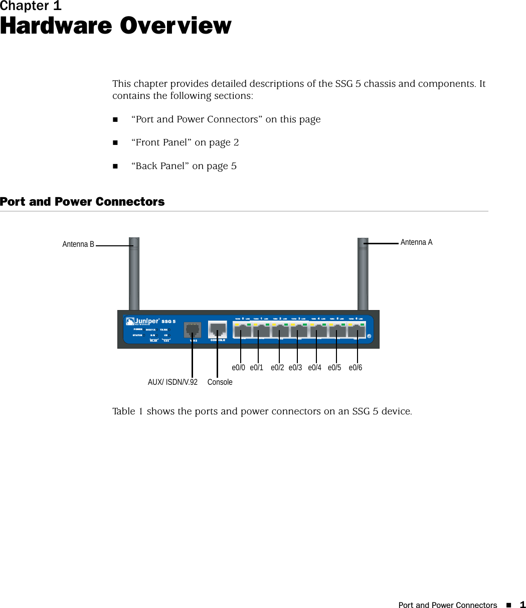

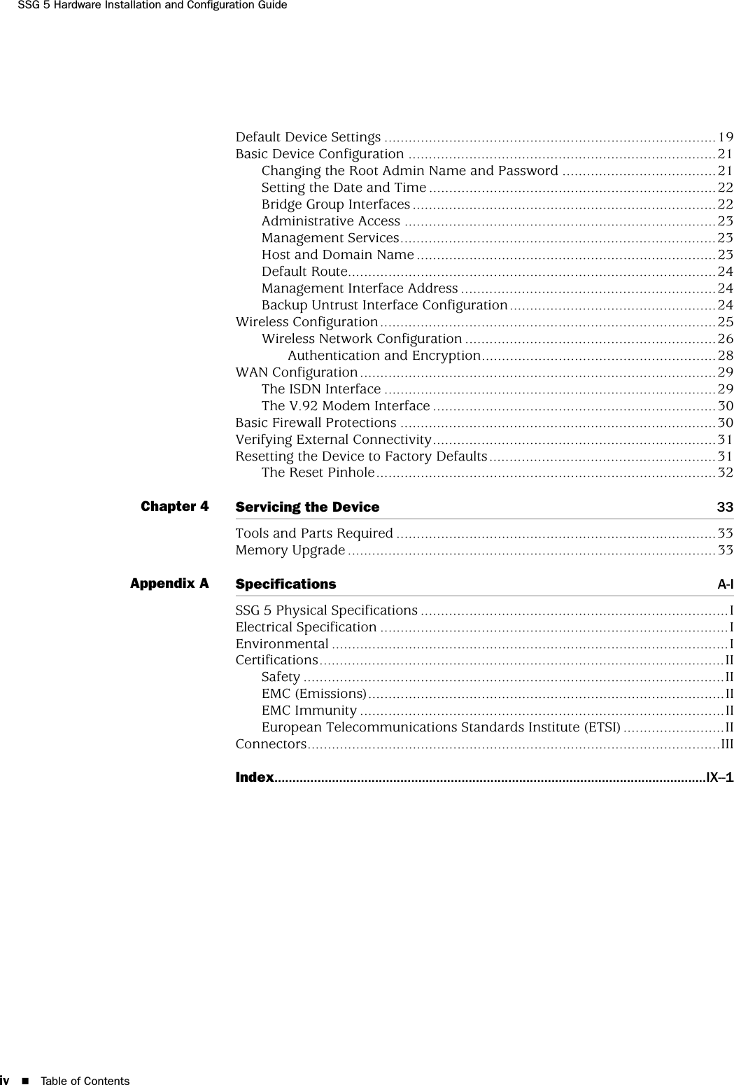
![SSG 5 Hardware Installation and Configuration Guide24 Basic Device ConfigurationCLIset hostname nameset domain namesaveDefault RouteThe default route is a static route used to direct packets addressed to networks that are not explicitly listed in the routing table. If a packet arrives at the device with an address that the device does not have routing information for, the device sends the packet to the destination specified by the default route.WebUINetwork > Routing > Routing Entries > New: Enter the following, then click OK:Network Address/Netmask: 0.0.0.0/0.0.0.0Gateway: (select)Interface: serial1/0 (select)Gateway IP Address: ip_addrCLIset route 0.0.0.0/0 interface serial1/0 gateway ip_addrsaveManagement Interface AddressThe Trust interface has the default IP address 192.168.1.1/24 and is configured for management services. If you connect the 0/2—0/6 port on the device to a workstation, you can configure the device from a workstation in the 192.168.1.1/24 subnetwork using a management service such as Telnet.You can change the default IP address on the trust interface. For example, you might want to change the interface to match IP addresses that already exist on your LAN. Backup Untrust Interface ConfigurationThe SSG 5 devices allow you to configure a backup interface for untrust failover. To set a backup interface for untrust failover, perform the following steps:1. Set the backup interface in the Null security zone with the unset interface interface [ port interface ] CLI command.2. Bind the backup interface to the same security zone as the primary interface with the set interface interface zone zone_name CLI command.To set the ethernet0/4 interface as the backup interface to the ethernet0/0 interface, do either of the following:NOTE: The primary and backup interfaces must be in the same security zone. One primary interface has only one backup interface, and one backup interface has only one primary interface.](https://usermanual.wiki/Juniper-Networks/SSG5/User-Guide-683344-Page-32.png)