Juniper Systems 19799AR BC04 Bluetooth Radio Module User Manual
Juniper Systems, Inc. BC04 Bluetooth Radio Module Users Manual
UserManual.wiki
>
Juniper Systems
>
19799AR User Manual
>
Users Manual
Contents
1.
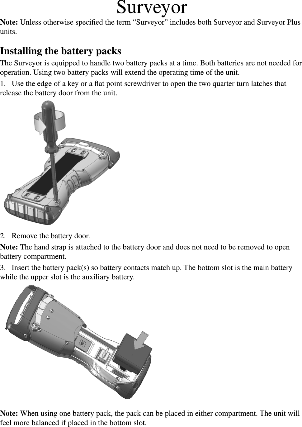
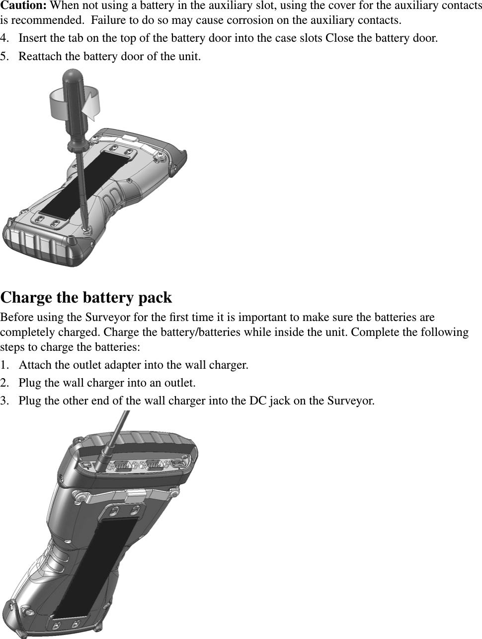
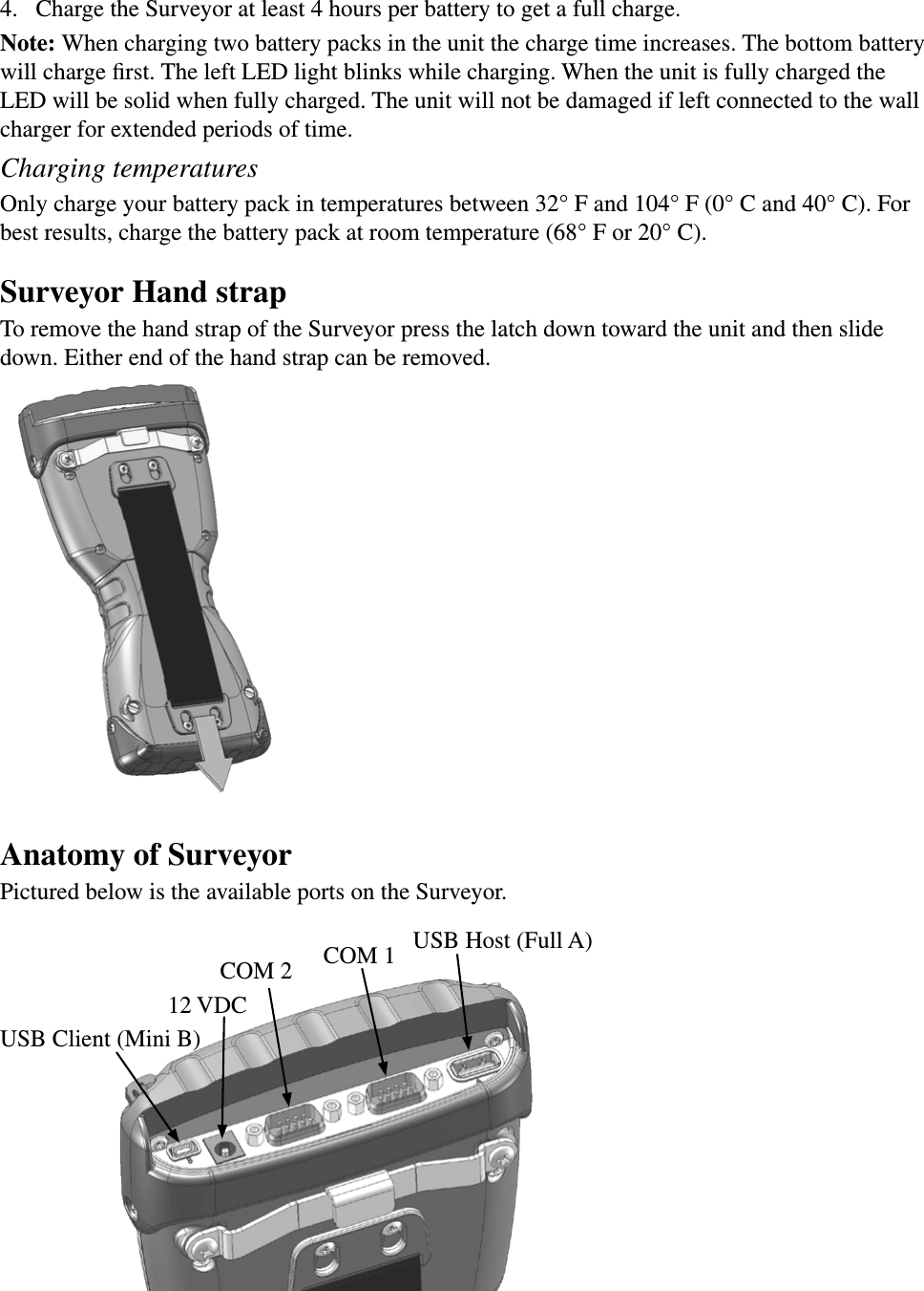
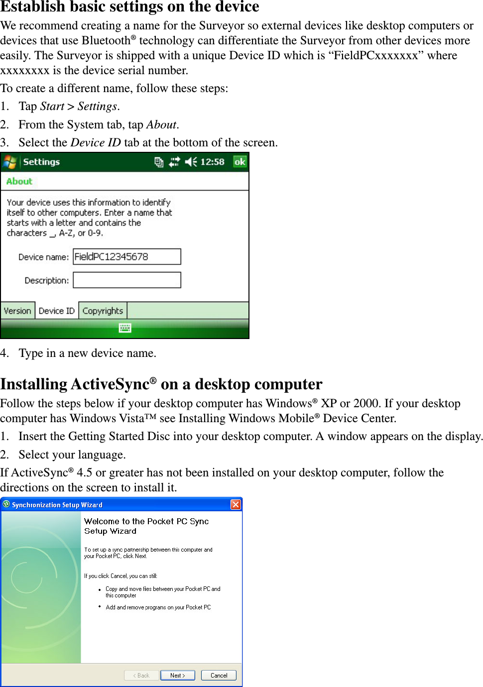
User Manual part 1
2.
User Manual part 2
3.
User Manual
4.
Users Manual
Users Manual
Navigation menu
Upload a User Manual
Namespaces
Wiki Guide
HTML
PDF
Info
Views
User Manual
Discussion / Help
Navigation