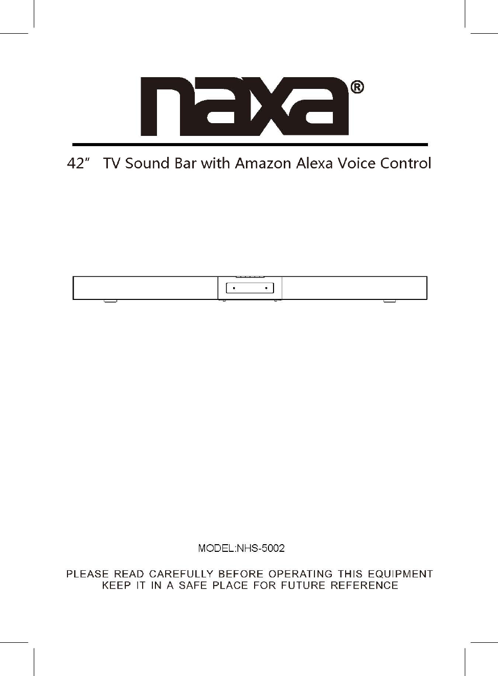
Junlan Electronic CAW70040 42 inch TV Sound Bar with Amazon Alexa Voice Control User Manual 1
Shenzhen Junlan Electronic Ltd 42 inch TV Sound Bar with Amazon Alexa Voice Control 1
User Manual

2
FCC NOTICE:
This device complies with part 15 of the FCC Rules. Operation is subject to the
following two conditions: (1) this device may not cause harmful interference,
and (2) this device must accept any interference received, including
interference that may cause undesired operation..
Any changes or modifications not expressly approved by the party responsible
for compliance could void the user's authority to operate the equipment.
NOTE: This equipment has been tested and found to comply with the limits for
a Class B digital device, pursuant to Part 15 of the FCC Rules. These limits are
designed to provide reasonable protection against harmful interference in a
residential installation. This equipment generates, uses and can radiate radio
frequency energy and, if not installed and used in accordance with the
instructions, may cause harmful interference to radio communications.
However, there is no guarantee that interference will not occur in a particular
installation.
If this equipment does cause harmful interference to radio or television
reception,which can be determined by turning the equipment off and on, the
user is encouraged to try to correct the interference by one or more of the
following measures:
-- Reorient or relocate the receiving antenna.
-- Increase the separation between the equipment and receiver.
-- Connect the equipment into an outlet on a circuit different
from that to which the receiver is connected.
-- Consult the dealer or an experienced radio/TV technician for help.
To maintain compliance with FCC’s RF Exposure guidelines, This equipment
should be installed and operated with minimum distance between 20cm the
radiator your body: Use only the supplied antenna.
FCC ID: OKUCAW70040
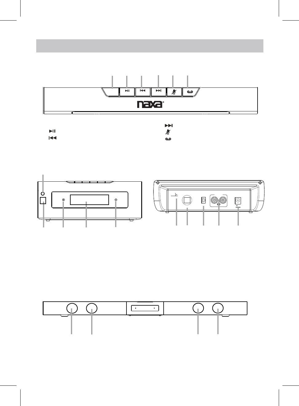
PROdUCT OvERvIEW
3
TOP VIEW
FRONT VIEW REAR VIEW
8. Remote IR Sensor 13. AUX IN 1 Jack
15. DC IN Jack
9. Built-in Microphone
10. Display
STANDBY
MODE VOL-
WPS VOL+
1 2 3 4 5 6
1.STANDBY/MODE Button
2. /WPS Button
3. /VOL- Button
4. /VOL+ Button
5. (Microphone On/Off) Button
6. (Communication) Button
7
8910 9
7. Communication Status LED Indicator
FM AN T
OPI CAL IN
AUX I N 1
AUX I N 2
LRDC 16 V, 3A
11 12 13 14 15
14. AUX IN 2 Jack
11. FM Antenna
12. OPTICAL IN Port
16 16 16 16
FRONT VIEW
16. Speaker
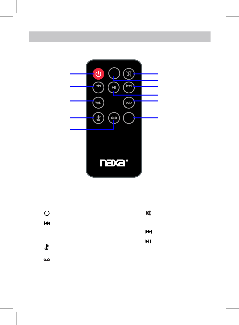
REMOTE CONTROL
(Mute)Button
(Previous)/ TUNE- Button
2.
9.
6.
10.
8.
(Play/pause) Button
VOL - (Volume down) Button
3.
1.
4. (Microphone On/Off) Button
(Next)/TUNE+ Button
VOL + (Volume up) Button
TUNE- TUNE+
WPS
MODE
NHS-5002
1
2
3
4
5
6
7
8
9
10
11
Power Button
5. (Communication) Button
7. MODE Button
11. WPS Button
4
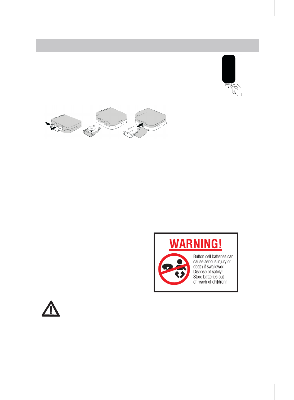
FIRST TIME USE
●Remove and discard the insulation as figure on the right.
●Replacing Batteries For Remote Control
1. Push and slide out the battery holder as figure 1 below.
2. Replace the battery with a new CR2025 button cell as the polarity
markings on the rear of the Remote Control.
3. Close the battery holder.
BATTERY PRECAUTIONS
Follow these precautions when using a battery in this device:
1. Use only the size and type of battery specified.
2. Be sure to follow the correct polarity when installing the battery as indicated in the battery
compartment, a reserved battery may cause damage to the device.
3. Do not mix different types of batteries together ( e.g: Alkaline and Carbon -zinc )
or old batteries with fresh ones.
4. If the batteries in the device are consumed or the device is not to be used for a long period of time,
remove the batteries to prevent damage or injury from possible leakage.
5. Do not try to recharge the battery not intended to be recharged; it can overheat and rupture.
( Follow battery manufacturer’s instructions.)
6. The batteries shall not be exposed to excessive heat such as sunshine, fire or the like.
7. Clean the battery contacts and also those of the device prior to battery installation.
8. The remote control supplied with a coin/button
cell battery. If the coin button cell battery is
swallowed, it can cause severe internal burns in
just 2 hours and can lead to death. Keep new
and used battery away from children. If the
Battery compartment does not close securely,
stop using the product and keep it away from
children. If you think batteries might have been
swallowed or placed any part of the body, seek
immediate medical attention.
CR2025
Fig.1 Fig.2 Fig.3
BATTERY INSTALLATION OF REMOTE CONTROL
Remote control operation range
●When there is an obstacle between the remote and the transmitter, the unit may not operate.
●When direct sunlight, an incandescent lamp, fluorescent lamp or any other strong light
shines on the REMOTE SENSOR of the unit, the operation of the remote may be unstable.
CAUTION
●Danger of explosion if the battery is incorrectly replaced.
●Replace only with the same or equivalent type.
film
5
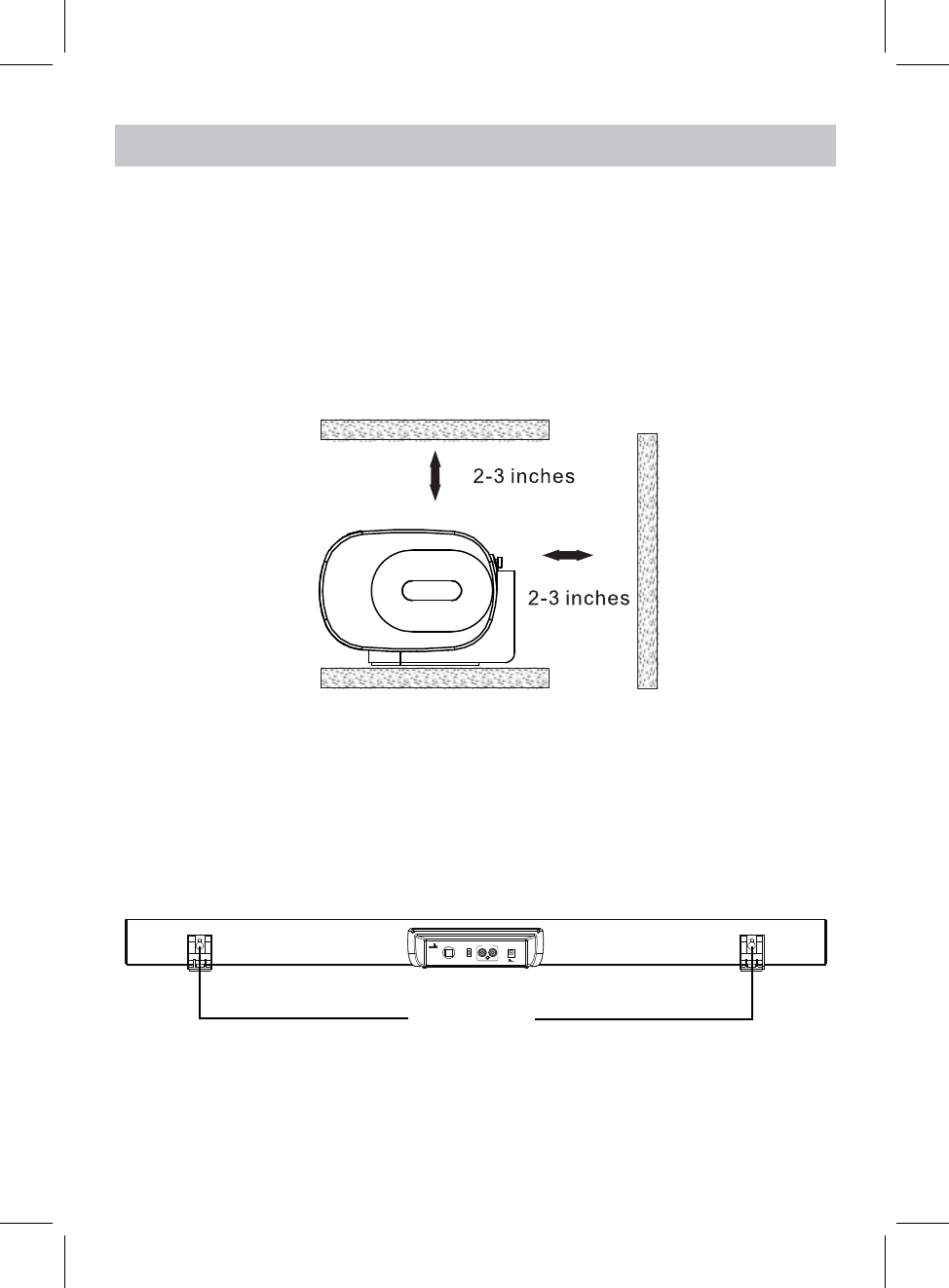
PLACEMENT AND MOUNTING
1. Placing the device on table - Ventilation
When placing the Sound Bar on an entertainment center, bookshelf, or any type of
enclosed space, be sure to allow at least 2-3 inches of space around the Sound Bar for
ventilation. If the Sound Bar is enclosed in a tight space, without ventilation, heat
generated from the Sound Bar could produce a potential heat hazard.
2. The Installation Distance
FM ANT
OPICAL I N
AUX IN 1
AUX IN 2
LRDC 16V,3A
29.1 INCHES
6
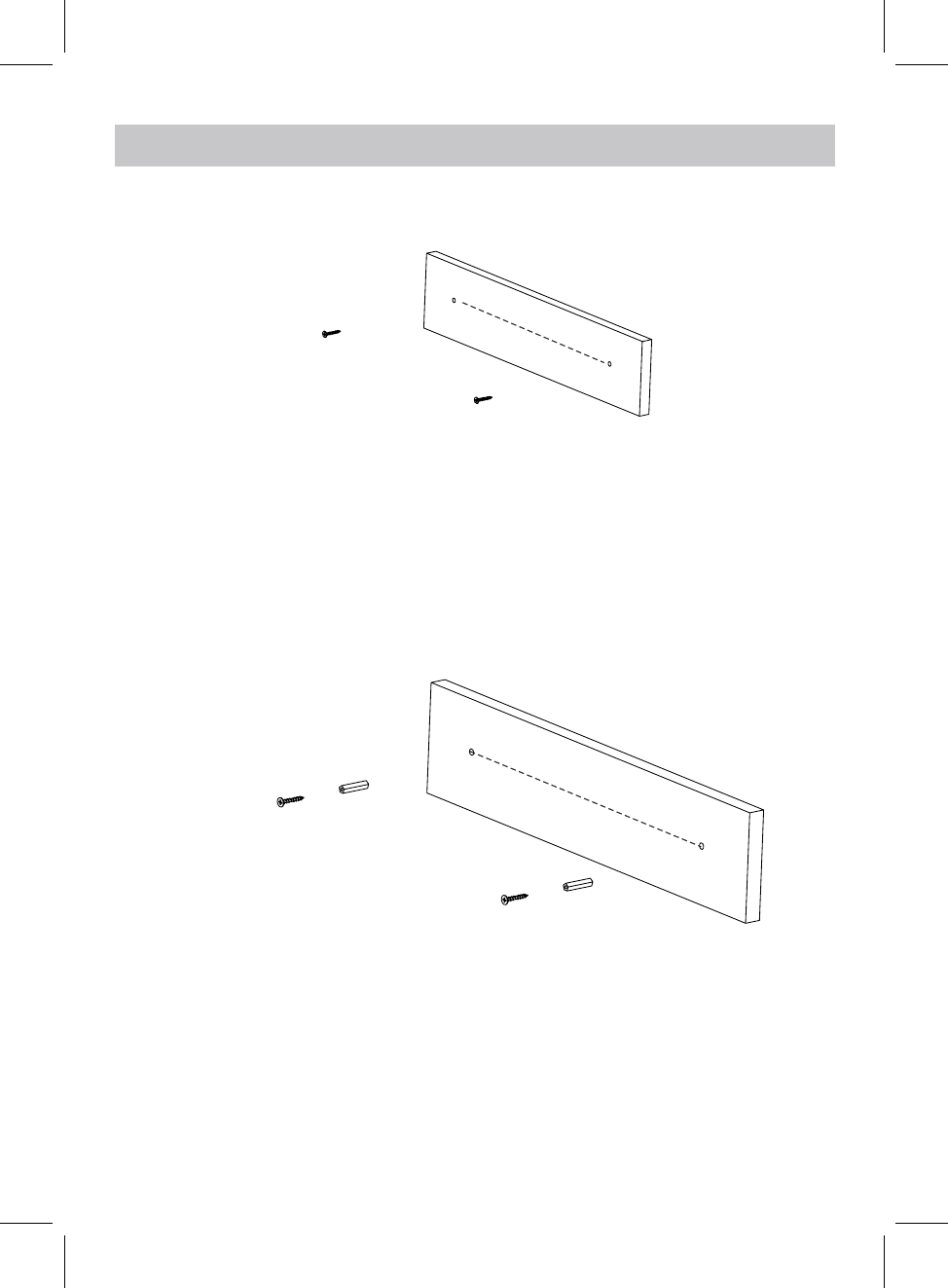
Mounting to a wall
2.1 Mountingto a wooden wall
A. Mark the position of the mounting screws on the wall using a pencil.
C. Put the sound bar onto the mounting screws. Make sure they are firm and stable.
2.2 Mountingto a brick wall
29.1 inches
B. Drill the screws directly into the marks that you have made on the wall and leave
approx. 0.3 inches length to hook the sound bar.
(screws not included)
(screws and plastic fixing plug are not included)
A. Mark the position of the mounting screws on the wall using a pencil.
E. Put the sound bar onto the mounting screws. Make sure they are firm and stable.
C. Insert the fixing plug and hammer into the holes.
D. Secure the screws into the fixing plug and leave approx. 0.3 inches length to hook
the sound bar.
B. Drill 2 holes on wall with a powerful electric drill.
29.1 inches
7

GENERAL OPERATION
BT.............................................................................................Bluetooth Mode
WIFI..................................................................................................WIFI Mode
2. Press and hold the STANDBY/MODE button on the unit or press the Button
3. During Playback:
on remote control to turn on the unit. Press the STANDBY/MODE button on the
unit or press the MODE button on remote control repeatedly to turn to desired
mode as below:
4. When finishing listening, press and hold the STANDBY/MODE button on the unit
or press the button on remote control to put the unit into standby mode.
1. Connect the AC/DC adapter to the unit and wall outlet. "WAIT" will sppear on
display.
AUX 1........................................................................................AUX IN 1 Mode
RADIO......................................................................................FM Radio Mode
AUX 2........................................................................................AUX IN 2 Mode
OPT......................................................................................OPTICAL IN Mode
Press and hold the VOL- or VOL+ button on the unit or press the VOL- or VOL+
button on remote control to adjust the volume.
Press the button on remote control to turn off sound, press again to resume.
8
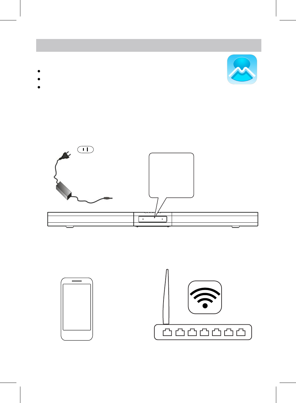
The App icon will appear as the figure on right after successful installation.
APP dOWNLOAd ANd INSTALLATION
MUzO Player
Download the MUZO Player from Apple App store for iOS devies.
Download MUZO Player from Google Play store for Android devices.
CONNECTION
desired WiFi network (router).
1. Plug one end of the adapter to DC IN jack of the speaker, then plug the adapter into the
Connect your iOS or Android device to the
wall outlet, press and hold the STANDBY/MODE button on the unit to turn on the unit.
Wait until "WIFI" blinks on display, now the speaker is ready for connection.
2. Turn on the WiFi on your iOS or Android device(smart phone or tablet with WiFi function),
9
WIFI SETUP
To AC Wall Outlet
To DC IN Jack
WIFI
to continue.
WIFI INFO
1Please enter Wi-Fi password:
Next
Wi-Fi: XXXX
<
Next
Password: Please enter Wi-Fi password
Press the
4. Inputing the WiFi password to make the speaker to connect to WiFi network(router),
Press the Next
<
Press the WPS key on device
WPS
PRESS TO ENTER SETUP M...
to put the device into network
setup mode.
Then click the "Next" button to
Next
2
5. on top of the speaker.
Press and hold the WPS button
button on your MUZO Player to continue.
10
during the connecting process.
6. There will be voice instructing like " searching for WiFi connection", " waiting for WiFi
connection"
PLEASE WAIT
3Wait for device to be
<
Cancel
connected to Wi-Fi...
Don't operate device during Wi-Fi setup.
Please wait for compltion of setup
patiently. It's usually finished in 60
seconds.
If you hear voice prompt for erro message.
please go back and retry
CONNECTED
Device is connected to XXXX
successfully
Current Wi-Fi strength of device:100%
Next
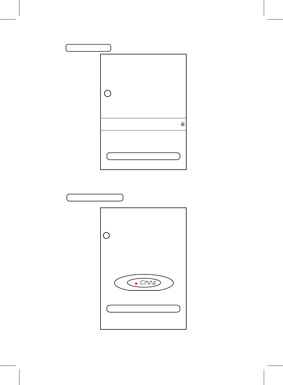
7. When the speaker is connected to the Wi-Fi (router) successfully, and the voice
sounds "Wi-Fi connected", the Indicator on front of the speaker will keep
11
If connection fails, please try again and repeat the above connecting steps.
communication status indicator
WHITE
FRONT VIEW OF THE UNIT
and "WIFI" will stay on display.
D
D
Search
Favorites
My music
TuneIn
iHeartRadio
Line In
Settings
Touch to search
Touch to listen the
collected favorite songs
Touch to listen native
songs
Touch to listen radio,
talks, sports, etc.
Touch to log on
Touch to switch to line
in mode
professional music
platform
Touch to log on
professional online
radio platform
online
songs
Touch to check version and feedback
TIDAL
Sportify
Touch to listen from
online songs platform
Bluetooth
Touch to switch to
Bluetooth mode
HOME PAGE INTERFACE
Click the " MUZO " on screen to enter homepage, operate as below instructions and the
screen instructions. Some platforms may need registration.
Touch to log in Amazon
Touch to add more
service
Amazon
12

1. Tap "Spotify" on MUZO homepage.
2. Input your account and password to log in.
3. Open the Spotify on your phone, tablet or PC, and play any song.
4. Tap the connect icon .
5. Pick your device from the list.
Before use, you have to create an spotify premium account for log in.
Before use, you have to create an iHeartradio account for log in.
Before use, you have to create a TIDAL account for log in.
1. Tap "iHeartradio" on MUZO homepage.
2. Input your account and password to log in.
3. Select the desired song and play.
1. Tap "TIDAL" on MUZO homepage.
2. Input your account and password to log in.
3. Select the desired song and play.
13
Licenses
The Spotify Software is subject to third party licenses found here:
www.spotify.com/connect/third-party-licenses.
SPOTIFY OPERATION
IHEARTRADIO OPERATION
TIDAL OPERATION
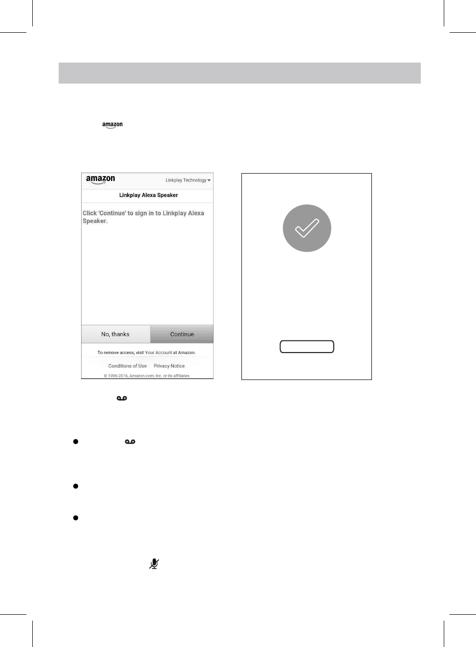
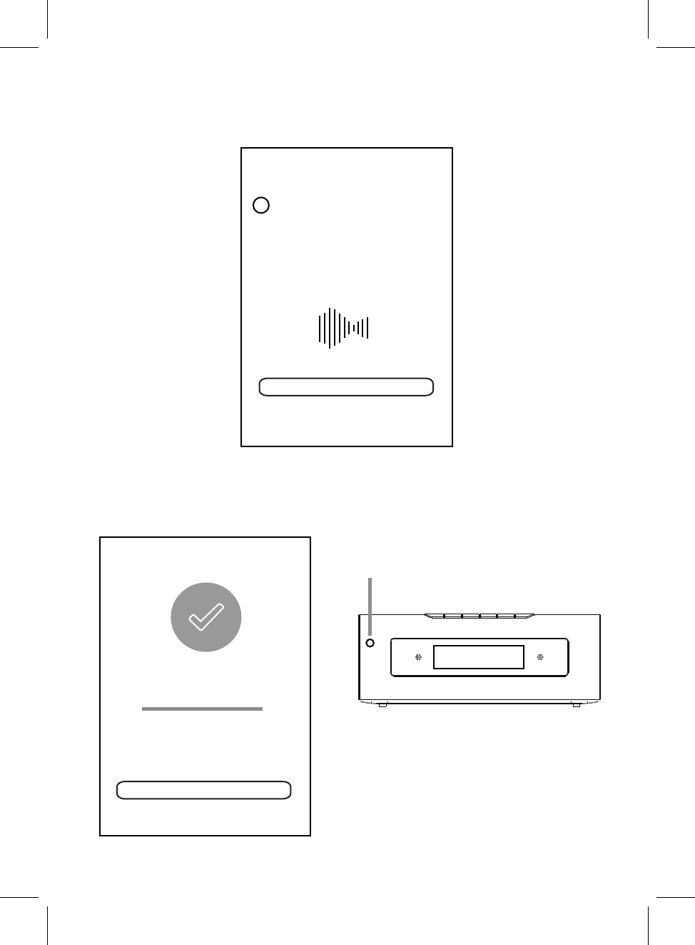
1. Touch on homepage, the log in window will pop up, input your account
AMAZON LINK PLAY ALEXA VOICE CONTROL
Before using Amazon linkplay Alexa voice control function, you must get an Amazon prime
account, creat an account on Amazon website.
Amazon
and password to log in.
2. If you have logged in before, the figures below will appear and operate as the tips.
3. Press the button once to activate the speaker to communicate before asking the
Example 1:
Press the button first, then ask the speaker, what's the weather like today?
The speaker will reply: the weather is not so cold.
The speaker will reply: it is 8 o'clock now.
Continute to ask the speaker to do other things, such as "Play Music!".
The speaker will reply: here is the station we found, the music will be played.
Amazon login successful
Next
14
speaker, (or you must say "ALEXA" to activate the speaker's communication system
without pressing any button).
Example 2:
Just say "ALEXA", then you can ask the speaker, what's the time now?
4. If you want to stop asking or inquiring the speaker, or avoiding external voice interference,
press and hold the button to turn off voice input, the communication indicator will
turn , press and hold this button again to turn on.
REd
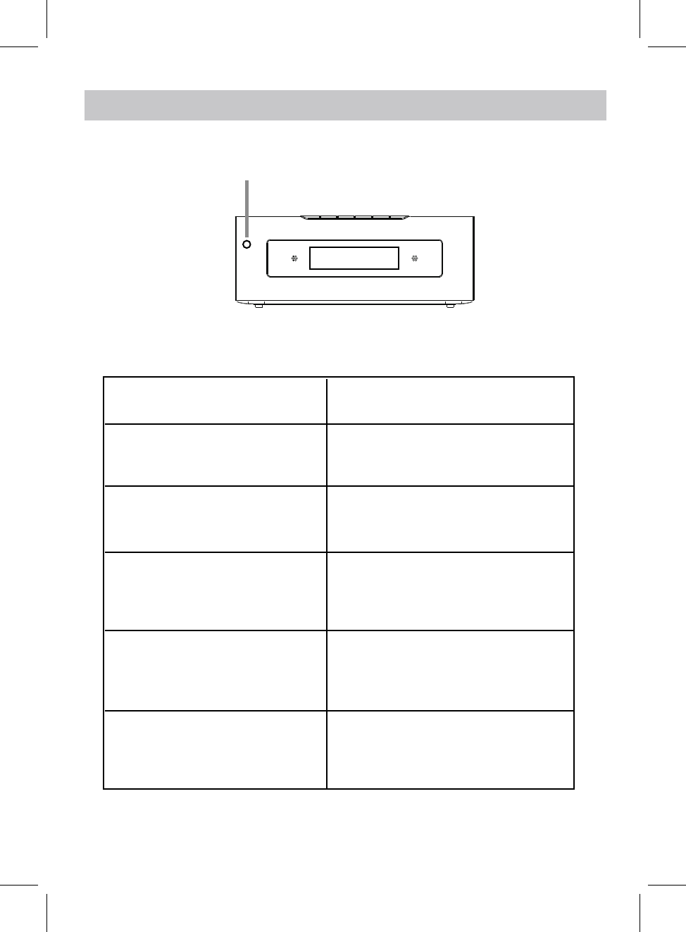
Idle
Listening Blue LED ON
Thinking Blue LED ON
Talking Blue LED blinks
SPEAKER STATUS
COMMUNICATION INDICATOR STATUS
LED STATUS
LED ON
White
Red LED ON
Microphone Off
15
communication status indicator
FRONT VIEW OF THE UNIT

BLUETOOTH OPERATION
Pairing the speaker with Bluetooth devices (phone or music device)
5. Once paired successfully, "BT" will stay on display and a tone will be heard.
6. If pairing is unsuccessful, turn off the speaker first and then re-pair following above steps.
3. Activate the Bluetooth function on your Bluetooth device (phone or music device). Please
refer to the manufacturer’s instructions of your device.
4. Once you have activated Bluetooth on your device, select the speaker name from the
pairing list of available Bluetooth devices.
7. Once you have paired the speaker with a device, the speaker will remember this device
and will pair automatically when the device’s Bluetooth is activated and in range.
During playing:
Press the button on the unit to pause, press again to resume playing.
Press and hold the VOL- or VOL+ button on the unit to adjust the volume.
10
1. Plug one end of the adapter to DC IN jack of the speaker, plug the adapter into the wall
NOTE:
The pairing name is " ".
NAXA NHS-5002
outlet, press and hold the STANDBY/MODE button to powr on the unit, wait until "WIFI"
appears on display.
2. Press the MODE button repeatedly until the "BT" blinks on display. Now it is in pairing
mode.
Press the or on the unit to skip to next or previous track.
16

RAdIO OPERATION
Befor using your unit for FM reception, unwrap and fully extend the antenna wire.
You may need to adjust the position of the antenna wire for maximum signal strength.
4. Press the or to listen the stored station.
3. Press the /WPS button on the unit to search up and down the band. The radio will
search the station available and store automatically.
1. Plug one end of the adapter to DC IN jack of the speaker, plug the adapter into the wall
outlet, press and hold the STANDBY/MODE button to powr on the unit, wait until "WIFI"
appears on display.
2. Press the MODE button repeatedly until the "RADIO" blinks on display.
17
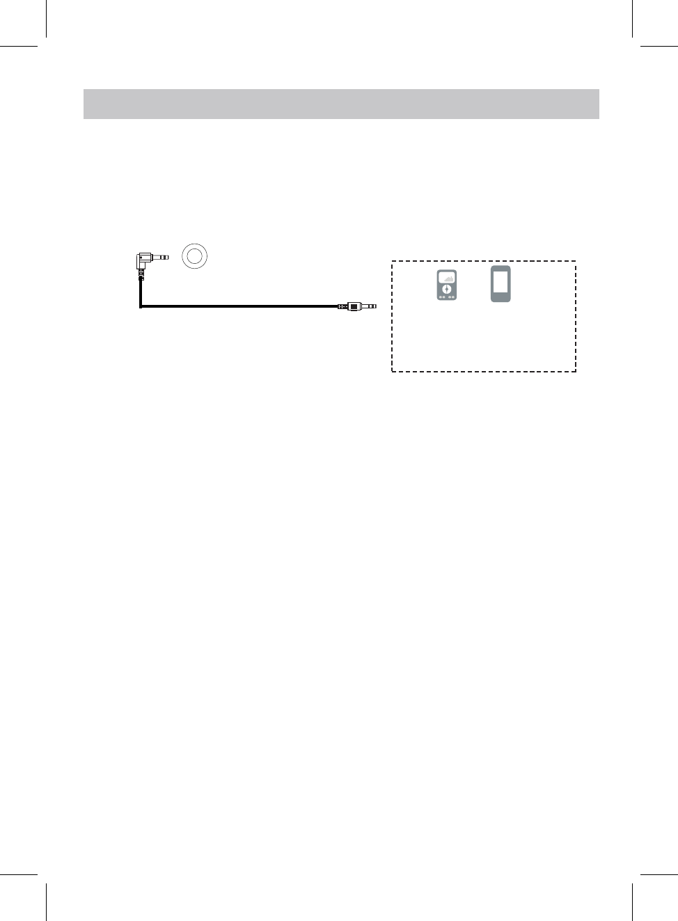
~ Insert the other end to the AUX IN jack on the rear of the main unit.
1. Connect the external audio device to the unit by an
~ Insert one end to the Phone; Line Out or AUX Out Jack on the external audio device.
audio connection cable with 3.5mm
stereo mini jacks as:
Mobile Phone
(Audio Connection Cable supplied) Connect to the Phones; AUX Out;
Line Out Jack of the external devices
(Such like MP3 Player; cell phones;
iPod/iPad ... etc)
4. Play music as usual on your external device.
MP3
AUX IN 1 OPERATION
2. Plug one end of the adapter to DC IN jack of the speaker, plug the adapter into the wall
outlet, press and hold the STANDBY/MODE button to powr on the unit, wait until "WIFI"
appears on display.
3. Press the MODE button repeatedly until the "AUX 1" blinks on display.
AUX IN 1
18
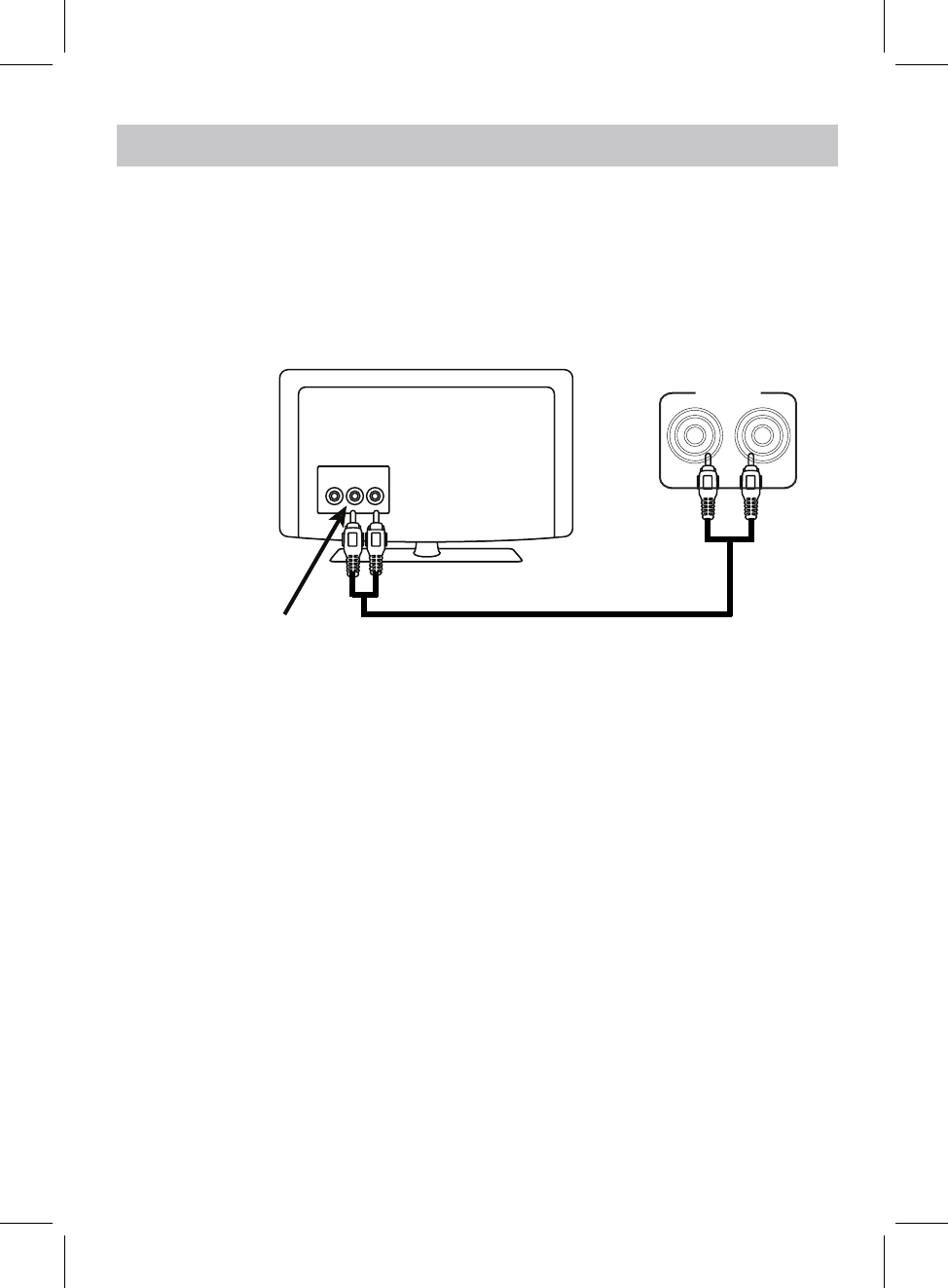
AUX IN 2 OPERATION
1. Plug one end of RCA White and Red cable into the LINE IN jacks on the rear of the unit.
Audio out jacks of
TV/DVD/VCR/DVR etc
LR
V
Plug the other end of RCA White and Red cable into audio out jacks of TV or
external device as the illustration shown as below.
AUX IN 2
LR
4. Play music as usual on your external device.
2. Plug one end of the adapter to DC IN jack of the speaker, plug the adapter into the wall
outlet, press and hold the STANDBY/MODE button to powr on the unit, wait until "WIFI"
appears on display.
3. Press the MODE button repeatedly until the "AUX 2" blinks on display.
19
An external Video/audio player(such as TV, DVD Player, VCR etc.) can be connected to
this unit and heard through the speakers.
white plug red plug
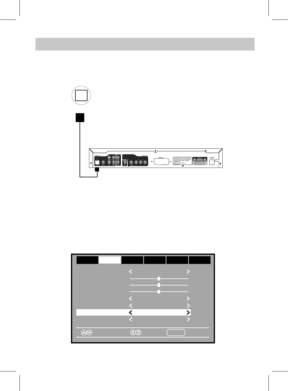
OPTICAL IN OPERATION
TV; DVD player; BD player... etc.
4. Power on the connected external player and start playback the Music as usual.
1. Connect the Optical out jack from the external audio Player (such like TV, DVD Player
BD Player …etc.) to the OPTICAL IN jack on the top of unit by the Optical Connection
Optical Connection Cable ( not supplied )
Cable (not supplied) as the figure below: ( F or PCM format only )
Turn on the digital audio output and set it to PCM (Plus Code Modulation) type similar to
the follows figure:
Bass
Treble
Balance
Select Move MENU Exit
Sound Mode Standard
Surround Off
AVL Off
Audio Language English
Picture Time Setup Lock Off
AudioAudio
Digital Output PCMDigital Output PCM
OPICAL IN
2. Plug one end of the adapter to DC IN jack of the speaker, plug the adapter into the wall
outlet, press and hold the STANDBY/MODE button to powr on the unit, wait until "WIFI"
appears on display.
3. Press the MODE button repeatedly until the "OPT" blinks on display.
20
TROUBLESHOOTING
Check the following before requesting service:
SYMPTOM POSSIBLE CAUSE POSSIBLE SOLUTION
Volume level of paired/connected device
is in low level
Rise the volume level of the
paired/connected device
Volume level of the connected/paired
device too high
Reduce the volume level of the
connected/paired device
BT not
unctioning
The external BT device had NOT paired to
the unit
Pair the external BT device to the
unit
The external BT device too far from the
unit
Place the external BT device
close to the unit
SPECIFICATTIONS
BT Version: 4.1
BT Operation Distance: 32 Feet in open area
PACKAGE INCLUDES
SPECIFICATIONS AND ACCESSORIES ARE SUBJECT TO CHANGE
WITHOUT NOTICE
f
No sound or
sound weak
Sound
distortion
Wifi Operation Distance: Feet in open area96about
about
1 X User's Manual
1 X AC/DC Adapter
1 X Audio Cable with 3.5mm Plug
1 X RCA Audio Cable
21
Power Source: DC16V 3A

LIMITED WARRANTY
NAXA LIMITED WARRANTY (“Warranty”) — For Product Categories Listed in Chart Below (as applicable, “Product”).
Before returning your Product for service under this Warranty, please read the instruction manual carefully and visit our website at
www.naxa.com for product updates and extended support documentation (e.g., Frequently Asked Questions, Common
Troubleshooting Guides, etc …). If you are still having trouble with your Product, please contact Naxa Customer Support.
Warning: Some Products may contain components that are small enough to be swallowed. Please keep out of reach of children.
Subject to the terms and conditions herein, Naxa Electronics, Inc. (herein after called “Naxa”) warrants to the original purchaser of the
Product (“Customer”) that the Product will be free from defects in material or workmanship under normal, non-commercial use
(“Defects”) for the applicable Warranty Period listed below.
Warranty Period encompasses separate “Coverage Periods” for Parts and Labor as listed in the table below. Each Coverage Period
begins from the original date of Customer purchase. If Customer returns a defective Product (or any component thereof) during the
applicable Coverage Period, Naxa will, at its option: (1) repair the Product (or any component thereof) or; (2) replace the Product (or
any component thereof) with a new or refurbished Product (or any component thereof), in either case free of charge to Customer for
Parts and/or Labor during the specified Coverage Period only, and excluding the applicable shipping charges noted below for which the
Customer is responsible. The foregoing states the Customer’s exclusive remedy and Naxa’s sole liability for breach of the limited
warranty contained herein.
This warranty specifically excludes any product that has been subject to or has defects resulting from:(a)any neglect or misuse by a
Customer; (b) an accident, improper application, violation of operating instructions for the Product, or any other Customer-induced
damage; (c) the alteration or removal of any Product serial number; (d) any modification or repair to Product (or any component
thereof) by any party other than Naxa or a party authorized in writing by Naxa; (e) any damage to Product due to power surges,
incorrect electrical voltage, misconnection to any device, or malfunction of any device used with the Product (or, as applicable, any
component thereof); (f) cosmetic damage to the Product caused by normal wear and tear; (g) shipping damage that occurs while the
Product is in transit; (h) damage caused by heat sources, sunlight, electromagnetic conditions, or other climatic conditions; or (i) any
acts of God. Refurbished products are not covered by this Warranty.
Product is sold to Customer for personal, non-commercial use only. Product is not warranted for commercial or rental use. In addition,
Product is not warranted against failure, and should not be used by Customer for any application where there is a risk that any data
stored on Product will be breached or otherwise compromised, or the data stored on Product is relied upon for medical or lifesaving
applications. Naxa disclaims any Warranty for any of the foregoing uses to the fullest extent permitted by law. Customer assumes any
and all risks associated with such uses of Product, and agrees to indemnify Naxa for any damages claimed for such uses.
EXCEPT FOR THE EXPRESS WARRANTIES STATED ABOVE AND TO THE MAXIMUM EXTENT PERMITTED BY LAW, ALL PRODUCTS ARE
PROVIDED “AS IS”, AND NAXA DISCLAIMS ALL OTHER WARRANTIES, INCLUDING WITHOUT LIMITATION ANY IMPLIED WARRANTY OF (I)
MERCHANTABILITY; (II) FITNESS FOR A PARTICULAR PURPOSE, OR; (III) NON-INFRINGEMENT OF THIRD PARTY RIGHTS. TO THE
MAXIMUM EXTENT PERMITTED BY APPLICABLE LAW, IN NO EVENT WILL NAXA BE LIABLE TO CUSTOMER OR ANY THIRD PARTY FOR
ANY INDIRECT, SPECIAL, INCIDENTAL, CONSEQUENTIAL, EXEMPLARY OR PUNITIVE DAMAGES, INCLUDING, WITHOUT LIMITATION, ANY
LOST PROFITS OR REVENUES, LOSS OR INACCURACY OF ANY DATA, OR COST OF SUBSTITUTE GOODS, REGARDLESS OF THE THEORY OF
LIABILITY (INCLUDING NEGLIGENCE) AND EVEN IF NAXA HAS BEEN ADVISED OF THE POSSBILITY OF SUCH DAMAGES, NAXA’S
AGGREGATE LIABILITY TO CUSTOMER FOR ACTUAL DIRECT DAMAGES FOR ANY CAUSE WHATSOEVER SHALL BE LIMITED TO THE
CUMULATIVE PRODUCT FEES PAID BY THAT CUSTOMER FOR THE PRODUCTS CAUSING THE DAMAGES, IF ANY.
This Warranty gives Customer specific rights, and Customer may also have other rights that vary from jurisdiction to jurisdiction.
All warranty returns must have an RMA number provided by Naxa Customer Support. An RMA number can be obtained by contacting
Naxa Customer Support by phone, email, or online by using the RMA ticketing system at www.naxa.com.
Naxa Electronics, Inc.
RMA Processing / Customer Support
2320 E. 49th St., Vernon, CA 90058
Email: support@naxa.com
Phone: (866) 411-6292
Web: www.naxa.com
Hours of Operation:
Monday – Friday
10:00 AM to 5:00 PM PST