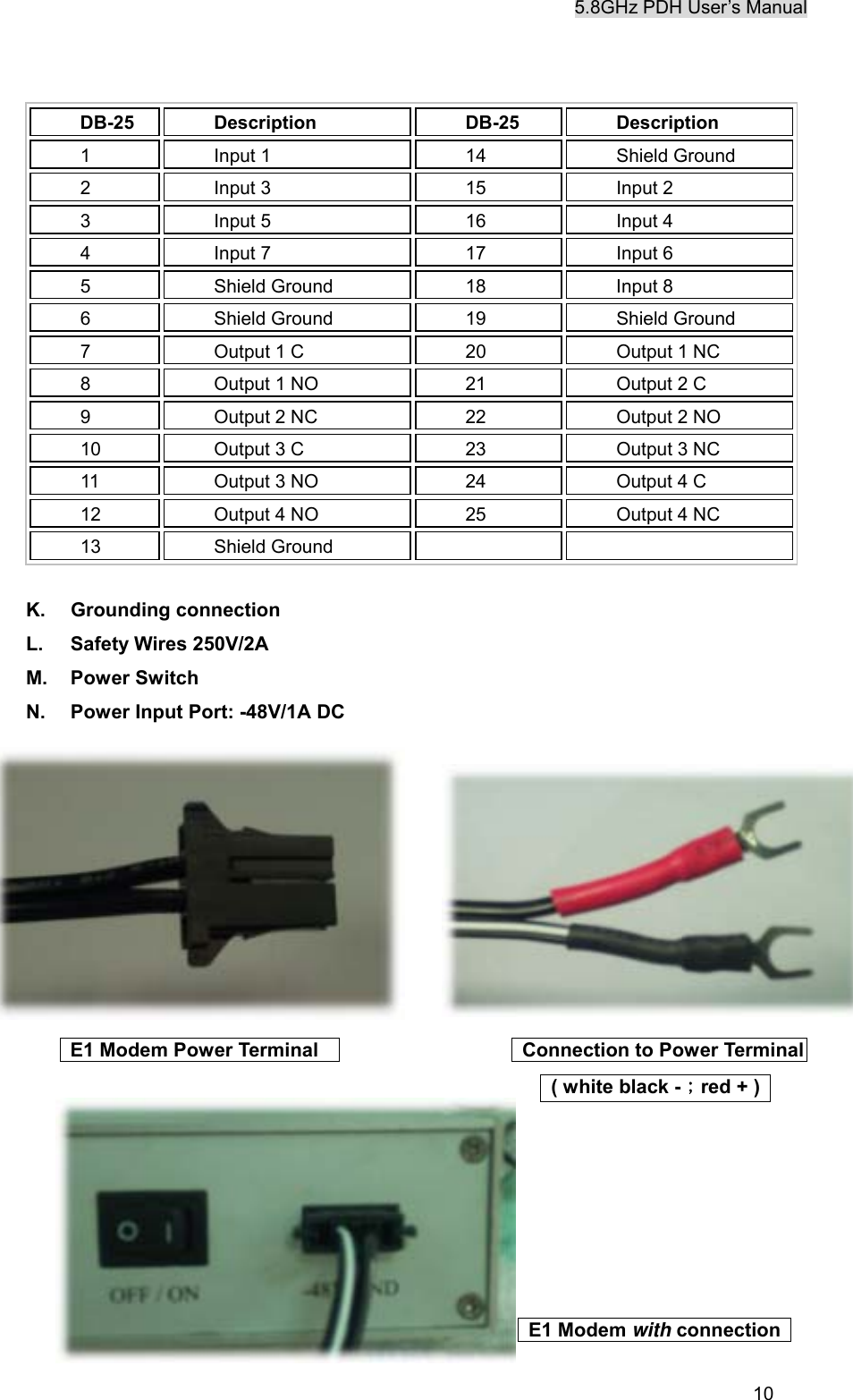
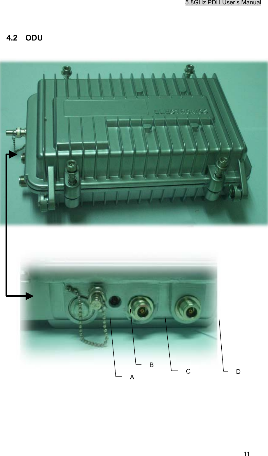
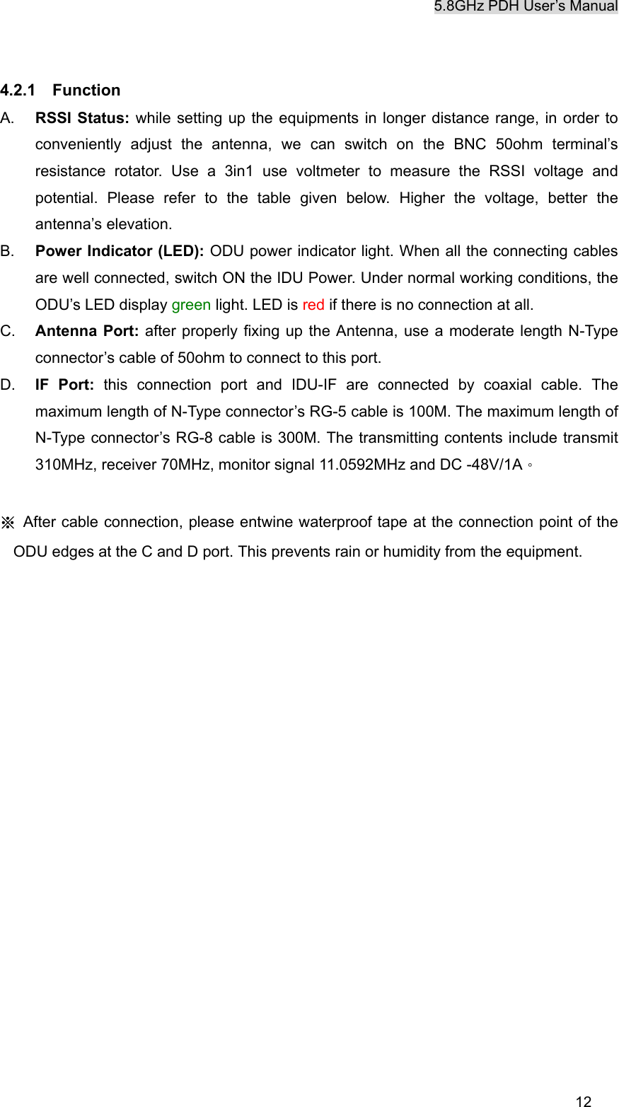
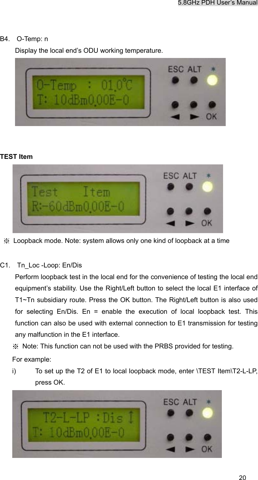
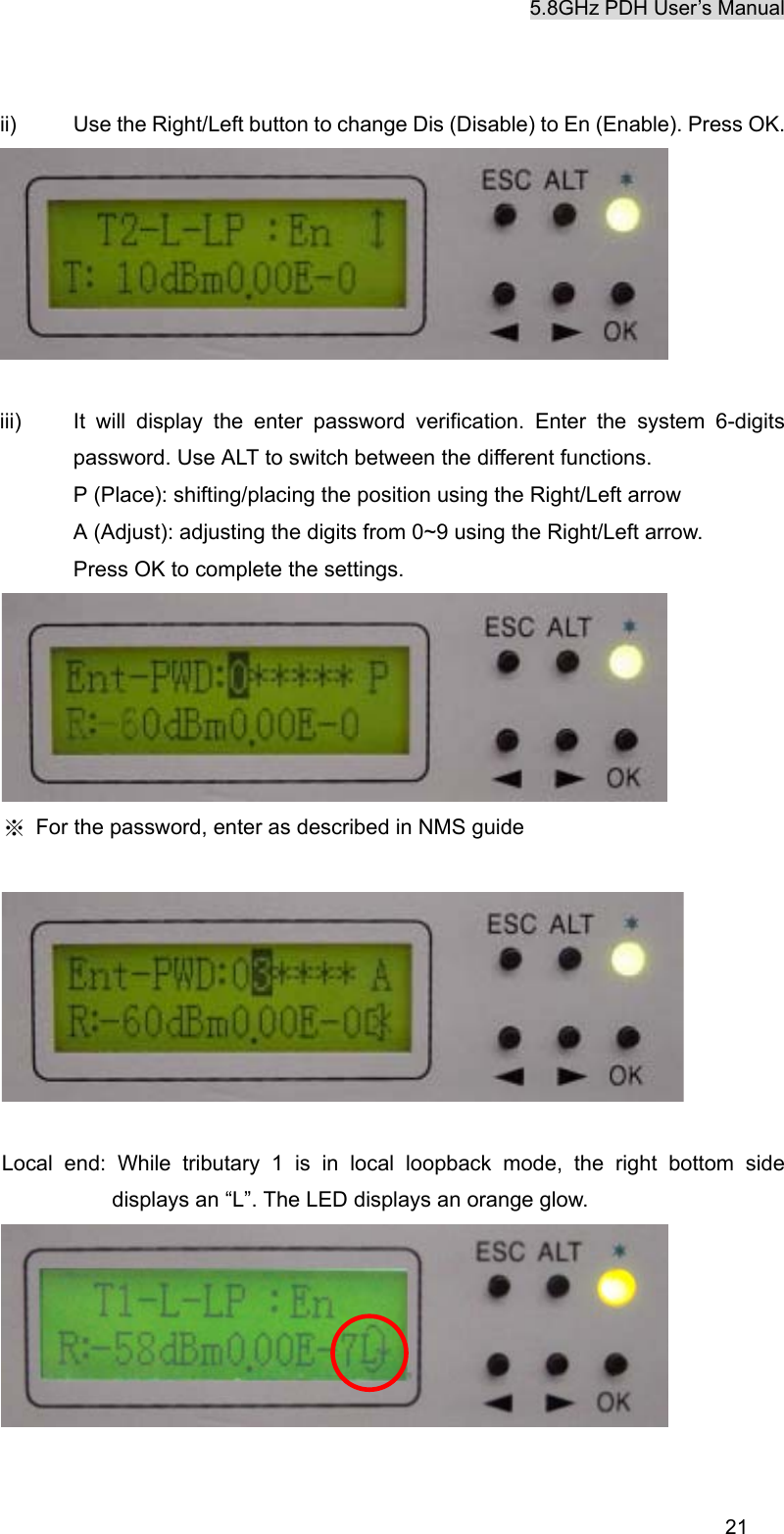
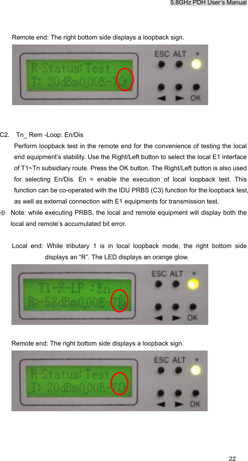
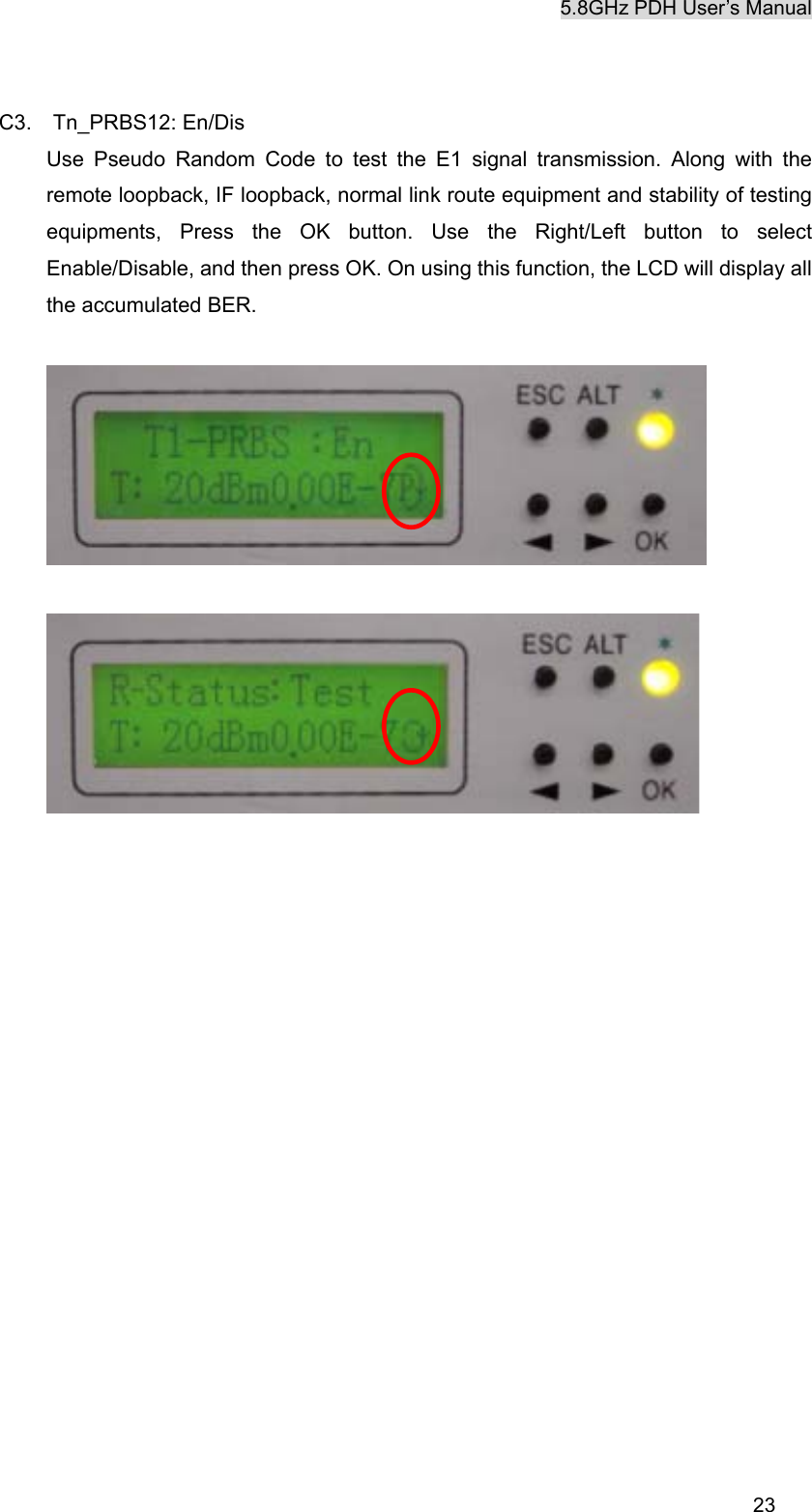
K Best Technology KB5802BR Point-To-Point Spread Spectrum Radio User Manual 5
K-Best Technology Inc. Point-To-Point Spread Spectrum Radio 5
UserManual.wiki
>
K Best Technology
>
KB5802BR User Manual
Revised User manual
Navigation menu
Upload a User Manual
Namespaces
Wiki Guide
HTML
PDF
Info
Views
User Manual
Discussion / Help
Navigation


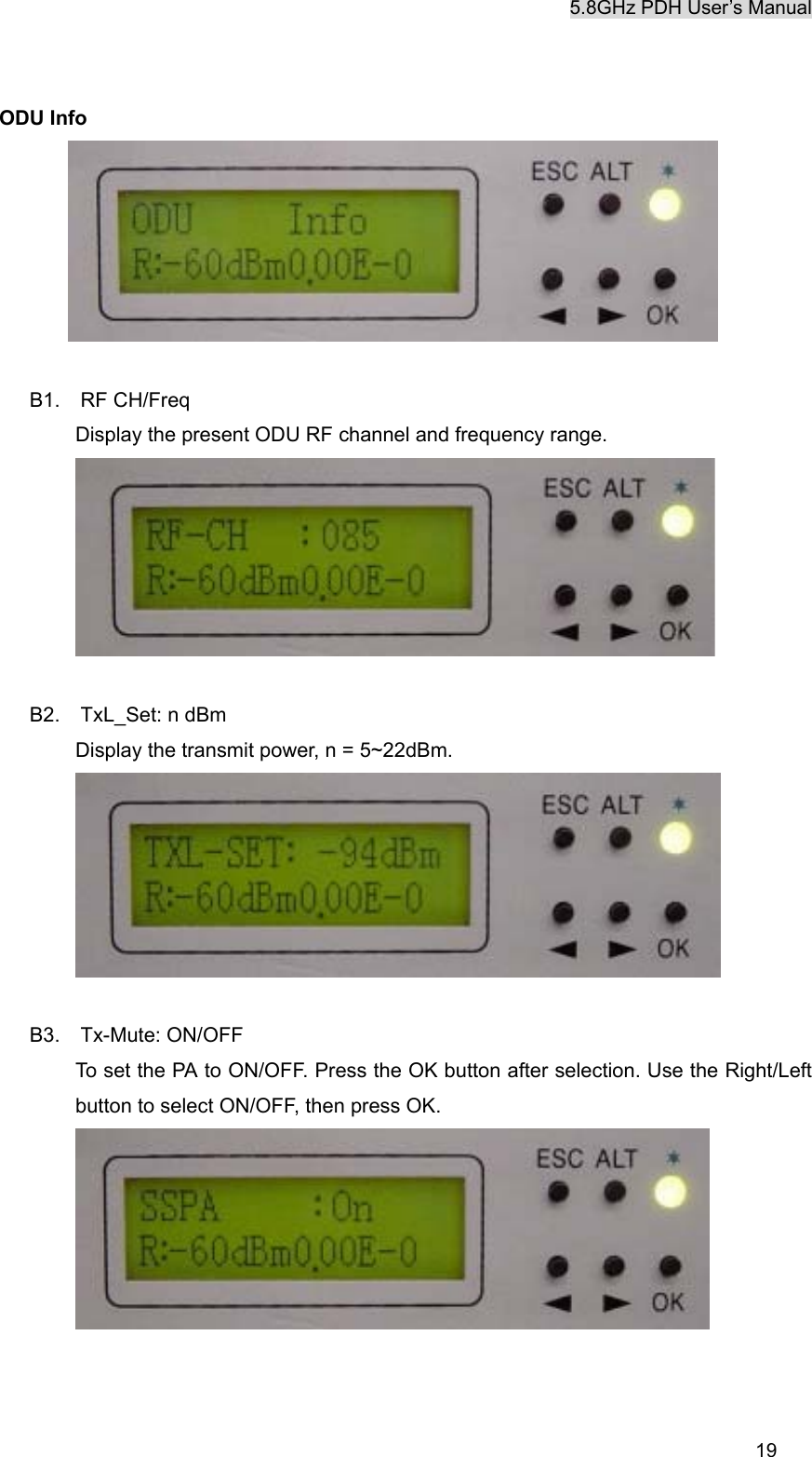


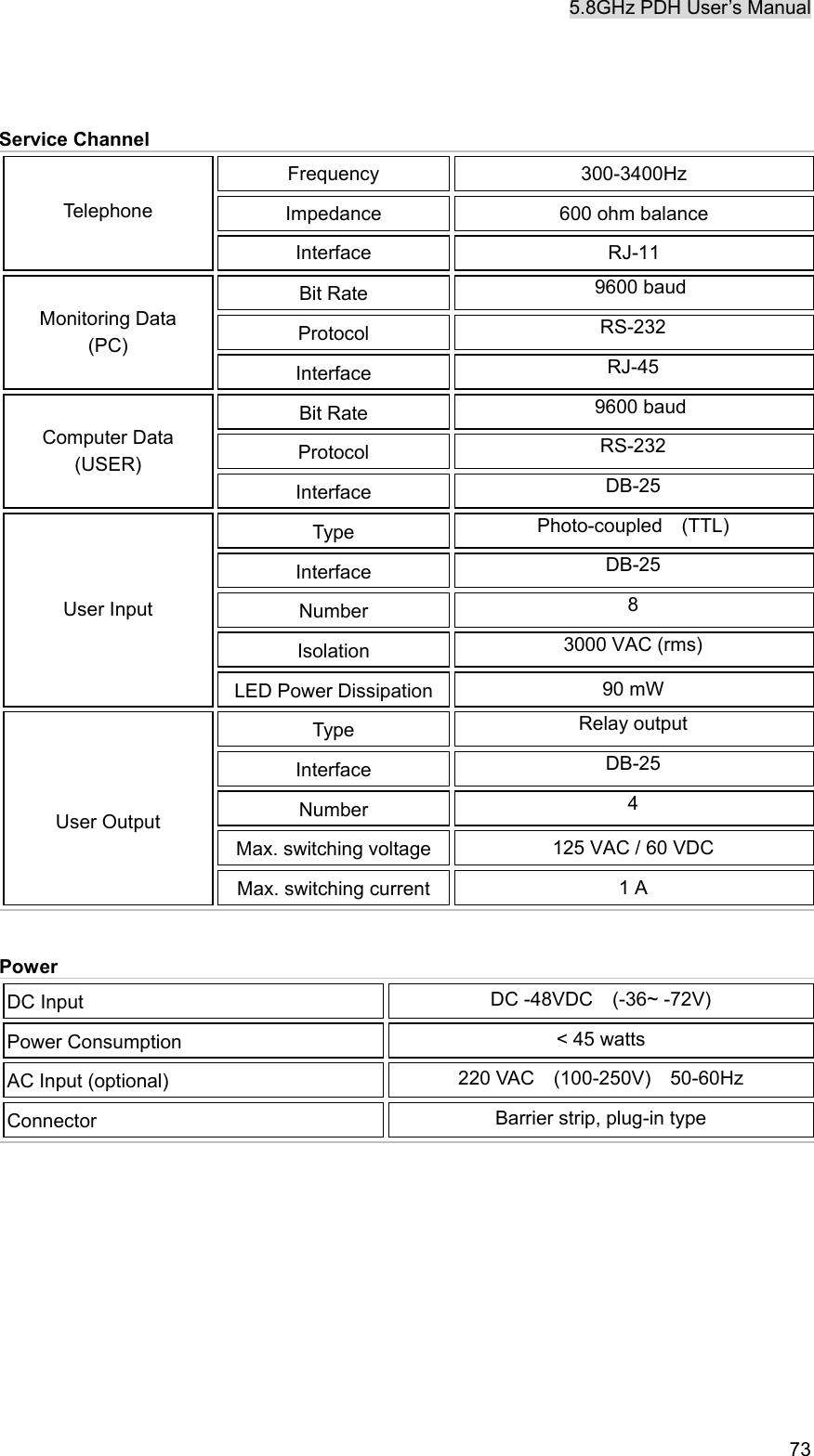


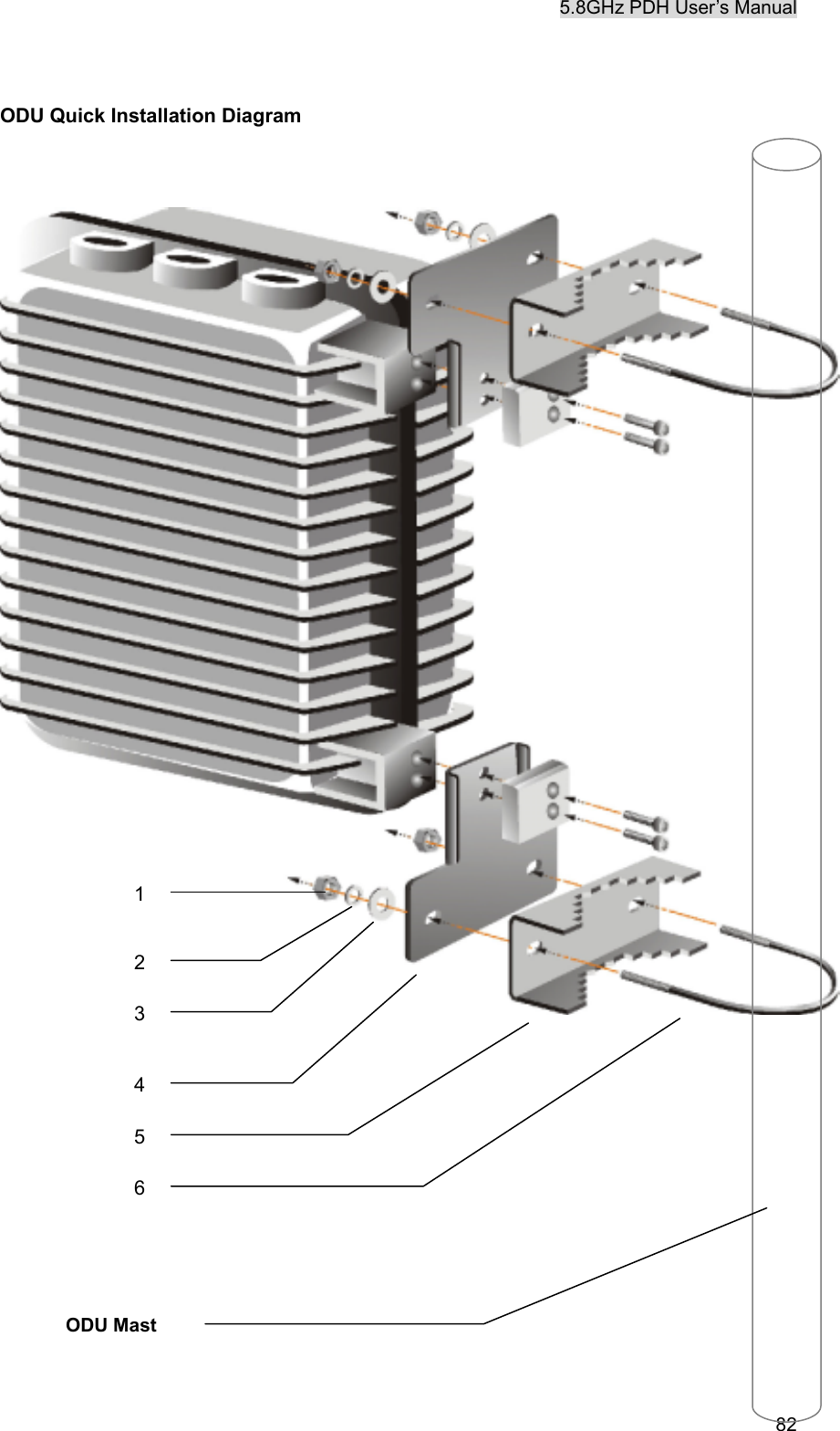
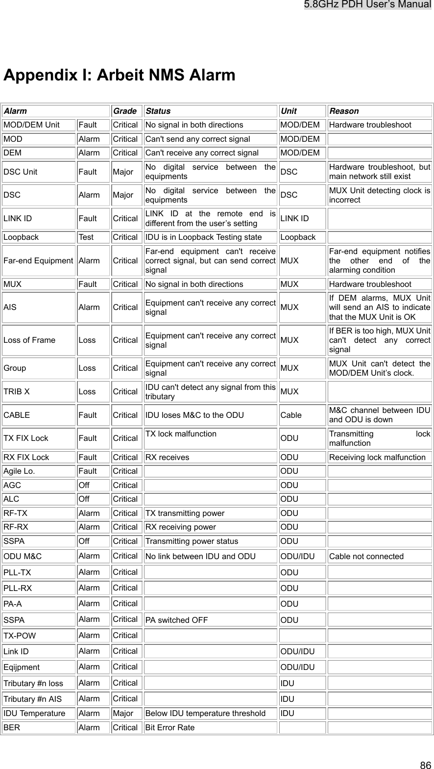
![5.8GHz PDH User’s Manual 81 Appendix F: ODU Installation Guide Parts of ODU assembly Nut[1] Washer[2] Washer[3] ODU Fastening Assembly Retaining Ring[4] Vee Block[5] U-Bracket[6] Name Quantity Screw[1] 4 Washer[2] 4 Washer [3] 4 Retaining Ring[4] 2 Vee Block[5] 2 U-Bracket[6] 2](https://usermanual.wiki/K-Best-Technology/KB5802BR/User-Guide-312349-Page-92.png)