K Best Technology KB5802BR Point-To-Point Spread Spectrum Radio User Manual 5
K-Best Technology Inc. Point-To-Point Spread Spectrum Radio 5
Revised User manual

※ NOTICE ※
The changes or modifications not expressly approved by
the party responsible for compliance could void the user’s
authority to operate the equipment.

5.8GHz PDH User’s Manual
i
※ IMPORTANT NOTE ※
To comply with the FCC RF exposure compliance requirements,
no change to the antenna or the device is permitted. Any change to the
antenna or the device could result in the device exceeding the RF
exposure requirements and void user’s authority to operate the
device.
To comply with FCC RF exposure requirement, the antenna used for this
transmitter must be fixed-mounted on outdoor permanent structures with a
separation distance of at least 2 meter from al persons and must not be
co-located or operating in conjunction with any other antenna or transmitter.
Outdoor units and antennas should be installed ONLY by experienced
installation professionals who are familiar with local building and safety
codes and, wherever applicable, are licensed by the appropriate government
regulatory authorities.Failure to do so may void the product warranty and
may expose the end user or Service Provider to legal and financial
liabilities.K-Best and its resellers or distributors are not liable for injury,
damage or regulation violations associated with the installation of Outdoor
Units or antennas.
Be sure that the outdoor unit, the antenna and the supporting structure
are properly installed to eliminate any physical hazard to either people or
property. Verify that the outdoor unit and the antenna mast are grounded so
as to provide protection against voltage surges and static charges. Make sure
that the installation of the outdoor unit, antenna and cables is performed in
accordance with all relevant national and local building and safety codes.

5.8GHz PDH User’s Manual
i
Table of Contents
1. INTRODUCTION .................................................................................................................. 1
2. SYSTEM BASIC FEATURES............................................................................................... 2
2.1 PDH SYSTEM................................................................................................................... 2
2.2 CORE TECHNOLOGY ......................................................................................................... 2
2.3 COMPOSITION AND PRINCIPLE ........................................................................................... 3
2.3.1 System Composition ................................................................................................ 3
2.3.2 System Principle ...................................................................................................... 4
3. TECHNOLOGICAL CHARACTERISTICS........................................................................... 5
4. PRODUCT OVERVIEW........................................................................................................ 6
4.1 IDU ................................................................................................................................. 6
4.1.1 Functions.................................................................................................................. 7
4.2 ODU .............................................................................................................................. 11
4.2.1 Function .................................................................................................................12
4.3 DATA TRANSMISSION PORT GUIDE................................................................................... 13
5. INTERFACE.......................................................................................................................... 10
5.1 REAR PANEL ................................................................................................................... 10
5.2 FRONT PANEL .................................................................................................................... 10
5.2.1 Public telephone..................................................................................................... 10
5.2.2 Definition of the IDU LCD Panel keys.................................................................... 11
5.3 LCD DEFINITION & OPERATION: ...................................................................................... 14
6. ENVIRONMENTAL CONDITION ....................................................................................... 31
6.1 CABLE ............................................................................................................................ 31
6.2 TEMPERATURE ................................................................................................................ 31
6.3 VOLTAGE AND DC POWER CONSUMPTION......................................................................... 31
6.4 HUMIDITY........................................................................................................................ 31
7. SOFTWARE INSTALLATION ............................................................................................ 32
8. ARBEIT NMS SOFTWARE ................................................................................................ 34
8.1 OPEN “ARBEIT” ............................................................................................................... 34
8.2 LOGIN............................................................................................................................. 35
8.3 INITIALIZATION................................................................................................................. 36
8.3.1 IDU Setting.............................................................................................................36
8.3.2 ODU Setting........................................................................................................... 38
8.3.3 Alarm Setting.......................................................................................................... 38
8.3.4 Cross Connecting................................................................................................... 39
8.3.5 User I/O Setting...................................................................................................... 40
8.4 SUPERUSER.................................................................................................................... 42
8.5 SYSTEM SETTING ............................................................................................................ 48
8.5.1 Background Setting................................................................................................ 48
8.5.2 COM port Setting ................................................................................................... 50
8.5.3 Record Saving Time............................................................................................... 51
8.6 USER SETUP................................................................................................................... 51
8.7 SYSTEM TEST ................................................................................................................. 53
8.7.1 Local Loopback .................................................................................................. 54
8.7.2 IF Loopback........................................................................................................ 54
8.7.3 RF Loopback ...................................................................................................... 55
8.7.4 Remote Loopback .............................................................................................. 56
8.7.5 PRBS Test.......................................................................................................... 57
8.8 SYSTEM RECORD ............................................................................................................ 58
8.8.1 Alarm Record ......................................................................................................... 58
8.8.2 Login Record.......................................................................................................... 61
8.9 HELP .............................................................................................................................. 62
8.9.1 Help Window.......................................................................................................... 63
8.9.2 About Arbeit ........................................................................................................... 63

5.8GHz PDH User’s Manual
ii
8.10 MONITOR......................................................................................................................... 64
8.10.1 Network Monitor................................................................................................... 64
8.10.2 Real-time Alarm ................................................................................................... 68
APPENDIX A: TECHNICAL SPECIFICATIONS...................................................................... 70
APPENDIX B: LCD ALARM DESCRIPTION ........................................................................... 74
APPENDIX C: LCD DISPLAY&FUNCTION TABLE............................................................... 76
APPENDIX D: FREQUENCY SPREAD SPECTRUM .............................................................. 78
APPENDIX E: 5.8GHZ ODU BLOCK DIAGRAM..................................................................... 80
APPENDIX F: ODU INSTALLATION GUIDE........................................................................... 81
APPENDIX G: RSL CALCULATION AND LINK BUDGET ..................................................... 84
APPENDIX H: ARBEIT NETWORK MANAGEMENT SYSTEM TREE ................................... 84
APPENDIX H: ARBEIT NETWORK MANAGEMENT SYSTEM TREE ................................... 85
APPENDIX I: ARBEIT NMS ALARM ....................................................................................... 86
APPENDIX J: ODU TROUBLESHOOTING GUIDE................................................................. 88
APPENDIX K: ANTENNA......................................................................................................... 90
5.8GHz PDH User’s Manual
1
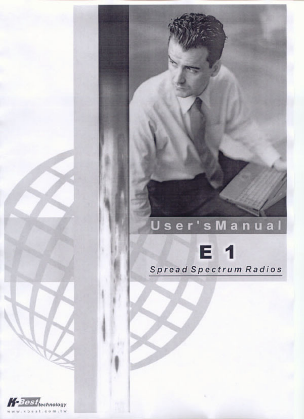
1. Introduction
PDH, Plesiochronous Digital Hierarchy, has been developed in these recent ten years to
a high frequency microwave, digital de/modulation, integrated digital multiplexing,
computer control and signal communication technique wholly into a wireless digital
signal communication mode.
Relevant products of “PDH equipment” has been extensively use in postal and
telecommunication service, power transmission, military affairs, various specialized
network especially in the interconnection between base stations of mobile
communication, large enterprises, schools and universities network connection. It has
been regarded as one of the quickest connection method and has been largely used in
provisional and urgent signal communication.

5.8GHz PDH User’s Manual
2
2. System Basic Features
2.1 PDH System
PDH system is different from the traditional microwave equipment in smaller size, lighter
weight, easy set up and can be conveniently moved from place to place. The main
characteristics lie in its advantageous use of high frequency band microwave
transmission (above 5.7GHz frequency), digital transformation, concise structure, quick
connection and adapt to complex topographical structure. Extensively use in mobile
phone base station’s interconnection and signal transmission, short distance local
connection, urgent communication, public and specialized network has large application
as well. The present wireless low frequency band is jam-packed and with the demand to
build a quicker communication network, the use of high frequency band PDH equipment
connection is especially meaningful.
2.2 Core Technology
PDH system includes a lot of high technique, which are:
(1) High RF microwave and other related components (amplifier, LNA, MIX, duplexer etc.)
(2) Frequency integrator randomly changes to different frequency band
(3) High amplifier gain control technique(ALC & ATPC)
(4) Advanced QPSK de/modulation
(5) Microwave frame de/multiplexer
(6) Digital band limit
(7) Digital equalizer
(8) Forward Error Correction
(9) Random N*E1 de/multiplexer, where N=1~32
(10) Digital cross-connection
(11) Computer monitoring and signal communication
(12) Network management
(13) Digital service
(14) Digital interface transformation
(15) Highly efficient and improved overall design
※ Audio frequency: Each voice signal needs a 64kbps; made of 8 bits-per-sample code,
A/D and D/A conversions.
※ E1 is an European Standard, 1*E1 is 30 voice channels, plus a channel for transmitting
and signaling, i.e. 32*64kbps = 2.048Mbps

5.8GHz PDH User’s Manual
3
2.3 Composition and Principle
2.3.1 System Composition
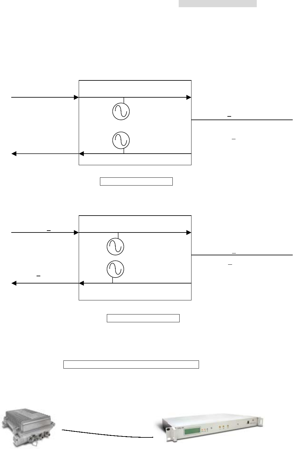
PDH system is composed of ODU and IDU. Other set of equipments include antenna
system, end- terminals etc.
ODU unit is the Rx/Tx unit of microwave signal. It is composed of other microwave units
(amplifier, converter, coded integrator etc.), duplexer, IF unit (dual converter, local
oscillator, IF processing segment etc.), monitor unit, remote unit, and power board.
IDU unit mainly comprises of QPSK modulator, de/multiplexer, monitor unit, network
management system, digital service, power system, other interfaces etc.
Antenna systems include antenna, matching connection, transformation and other
installation assembly for fixing on the rooftop.
ODU unit and IDU unit are connected by an IF cable.
PDH System Block Diagram (1+ 0 mode)
MODEM Monitor
Unit
MUX Service
Power
PC NMS
network
management
system
Phone
ODU Antenna
N*2Mb/s

5.8GHz PDH User’s Manual
4
2.3.2 System Principle
N number of E1 signals, digital service, 9600b/s system net control and 9600b/s
computer data communication etc. multiplexed in a multiplexer to a specific microwave
frame code. After QPSK modulation, the system sends the transmission to the ODU
through only one IF cable. It enter the ODU upstream IF signal communication through
equalized electric circuit interface, higher frequency converter, power amplifier, filter,
duplexer and are then transmitted out through the antenna system.
After the opposite terminal’s antenna system receives the microwave signals, it is passed
on to the duplexer, LNA, low frequency converter, filter, dual frequency converter and
then to the IDU. In the IDU, it passes through the QPSK demodulator to recover the
microwave frame signal. This frame signal is then processed through de-multiplexer to
recover the N number of E1 signal and other service signal.
The monitor unit in the equipment is controlled by the CPU (central processing unit) to
function as: monitoring, controlling, dispatching, alarming, processing and indicating
signals etc. Based on the statistical result of BER test in de/multiplexer, we have
1E-3BER, 1E-6BER and frame loss signals.
Digital service adopts the Analog rule of 64kbps and PCM (Pulse Code Modulation)
decoder method to service communication, complete address selection and full address
function. Through simulation transmitting and receiving, to complete the multiple
categorized public affairs connection. The dialing mode adopts DTMF system.
System network management uses PC machine of above PII operating system.
Under WINDOW environment’s SNMP network management software, it is possible to
hold communication through the same equipment, collect all the equipment’s status in the
network and select records for printing. The introduction of animation design makes the
network topology and equipment selection status crystal clear.

5.8GHz PDH User’s Manual
5
3. Technological Characteristics
Traditional digital microwave equipment generally transmits E1 signal only, so there is
always the need to apply for frequency channel because of technological limitations.
In recent years, there is a dramatic change in the structure, composition and application
of digital microwave communicative equipment. The traditional system of transmission
has been changed to the integration of transmitter and receiver as well as from fixed
frequency to the possibility of frequency conversion from low to high frequency band. In
view of the high frequency digital microwave communication system’s new changes and
additional newer characteristics, we had already improved the traditional system to a
great length.
K-Best’s PDH system has the following technological characteristics:
-- high frequency band: 5.8、13、15GHz to 26GHz
-- complete capacity: 2*2Mbps、4*2Mbps、8*2Mbps、16*2 Mbps
-- flexible interface: suitable for multiple network and business connection
-- IDU and ODU unit connected by a single IF cable up to 300m length, thereby,
decreasing the RF transmitting loss and increasing the receiving signal-to-noise ratio
(S/N)
-- channel conversion, flexible spread network and least backup support
-- digitally advanced QPSK or 16QAM de/modulation
-- powerful monitoring function: simple and easy to operate LCD display. With the overall
status display and loopback test function, subscribers can easily maintain the system
without the need of special equipment to ascertain where malfunction has occurred
-- improved SNMP network management system suit a lot of different topological
structure. It can manage up to 255 number of station equipments and also extend the
monitoring support to other microwave equipments
-- quick and easy installation
-- equipment adopt a considerable amount of advanced technology and modularity to
design the structure which is highly reliable, small, artistic, quick to produce and easy
to maintain.
-- frequency bandwidth and spectrum transmitting RF spurious fits the specifications
5.8GHz PDH User’s Manual
6
4. Product Overview
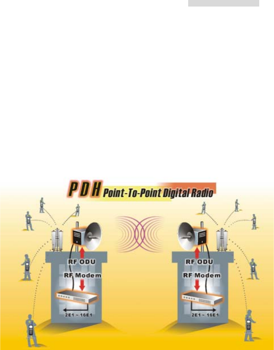
4.1 IDU
Front Panel
Rear Panel
4E1 Modem
Transmission Line Power Cord
A B
C D
E F H K M
G I L
J
5.8GHz PDH User’s Manual
7
4.1.1 Functions
A. LCD Display: Display the normal working temperature, receiving power and BER.
B. LCD Control: LCD glows under normal working condition. If there is an alarm, the
LCD back light will automatically glows for 2 minutes and display the alarming status.
The buzzer goes off until it is turn off. To shut off the buzzer temporarily, press the
monitor control. LCD will display a crossed off speaker sign. Until and unless the
alarm is shut off, never switch on the buzzer manually. Alarm display goes off
gradually.
C. LED: LED glows on switching the power ON. LED display green light under normal
working condition and red light under critical alarming condition.
D. Service Phone Interface: Service between the stations. Insert RJ-11 into any analog
phones and dial the IDU DSC number. If there are more than one equipments in the
same network, you may dial “***” and group connection will be connected.
E. Reverse E1 connector (BNC): 2E1 2*Tx/Rx, 4E1 4*Tx/Rx, 8E1 8*Tx/Rx, 16E1
16*Tx/Rx.
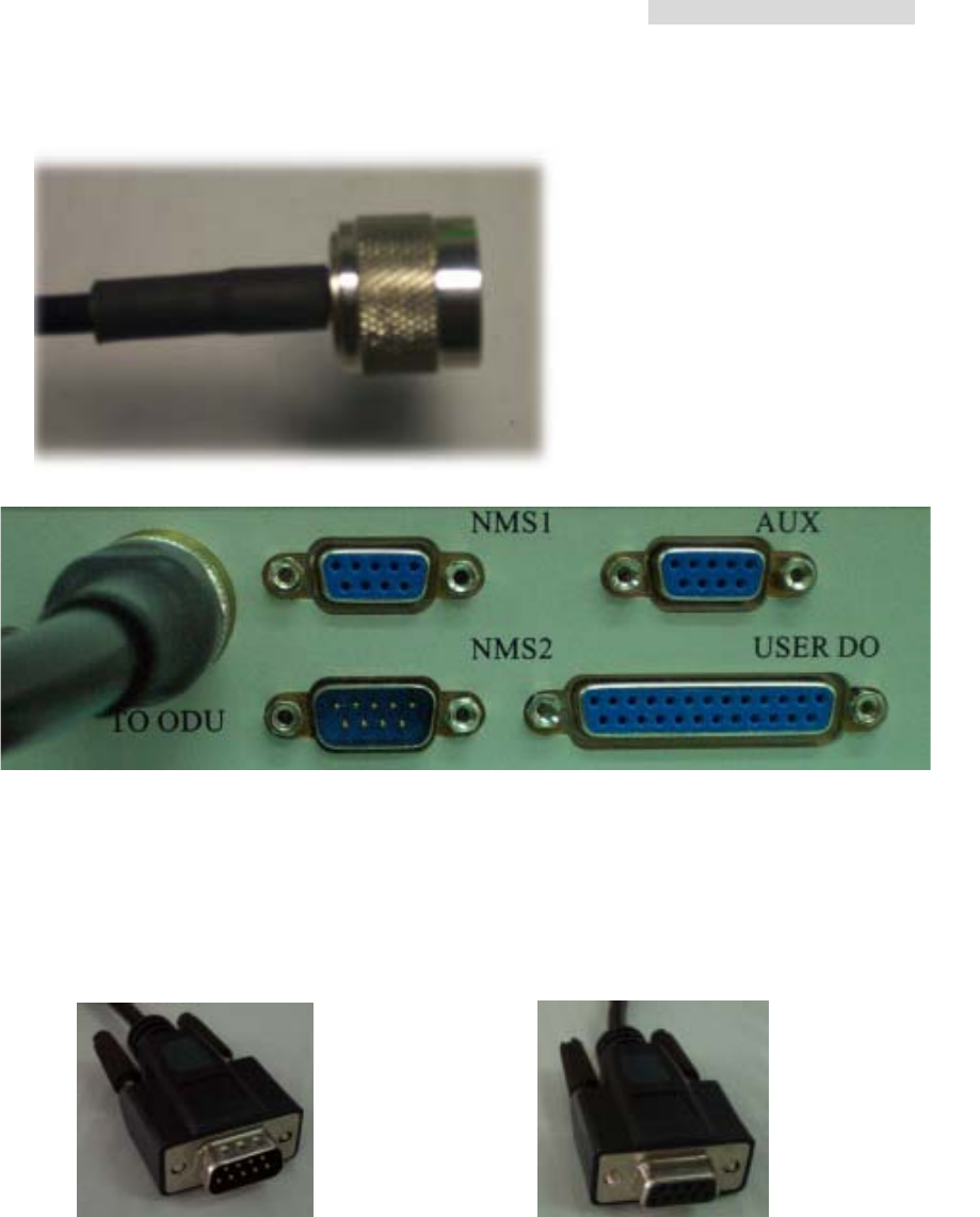
F. IF Transmission Port (N-Type 50Ω): Transmission contents include transmitter
310MHz, receiver 70MHz, monitoring signal 11.0592MHz, DC -48V/1A. Maximum
transmission 100M when using N-type connector’s RG-5 cable. Maximum
transmission 200M when using N-type connector’s RG-8 cable.
ESC = exit
ALT =
switch
functions
Left = left arrow
Right = right arrow
OK = confirm
Under normal working
condition, display the
indoor and outdoor
temperature, receiving
power and online BER.
The display refresh every
1~2secs.
5.8GHz PDH User’s Manual
8
E1 modem without IF cable connection
G. Monitor port (NMS1): Connect the COM1 or COM2 (RS-232) of the computer to this
port. Open the Arbeit NMS working window to function as the PDH remote terminal
display. Other than monitoring the local IDU and ODU, it may also monitor the remote
equipments.
Transmission Line (DB9 male + DB9 female)
N-type connector’s RG-5 cable
5.8GHz PDH User’s Manual
9
E1 Modem
without transmission line
E1 Modem
with transmission line
H. String Connection Port (NMS2): When there are more than two sets of equipments
in the local stations, connect the IDU-NMS2 of this equipment to the IDU-NMS1 of the
other equipment. When the NMS2 are connected, the service telephone between
these equipments is put into function.
I. Data Transmission Port (AUX): Use the WINDOWS HyperTerminal functions as
given in Section 9.2. Connect the COM1 or COM2 (RS-232/DB-9) of the pc’s to this
port for simple file and data transmission.
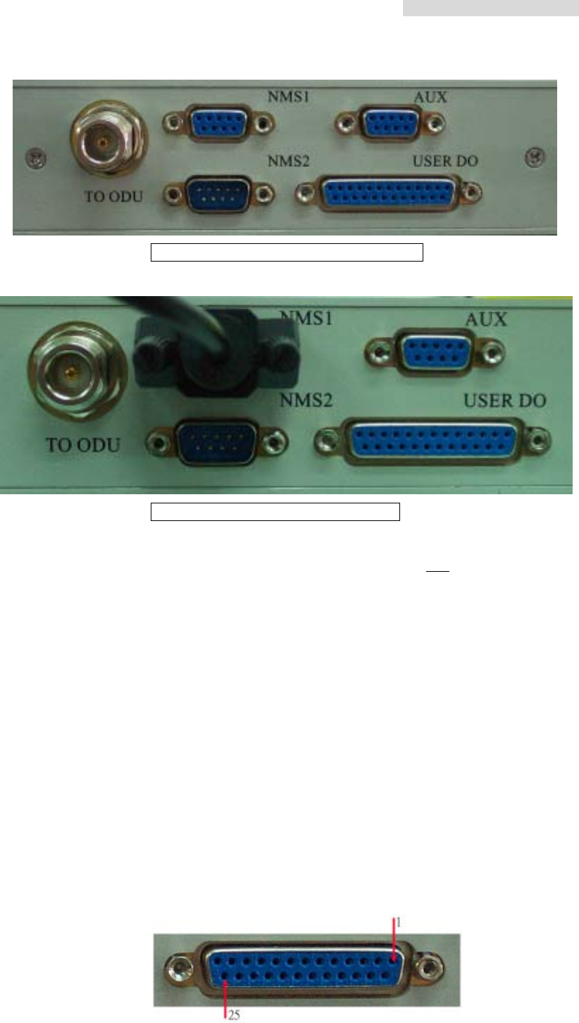
J. Environment Detection Port: Allows users to fully monitor the central controlling
room for the local station. For example: In the absence of human control in the remote
stations, the central controlling server is able to receive all fire alarms, power supply
etc. information. It can also control the light switches, oil switches etc. It totally
realizes the possibility of an intelligent management. All together, there are 8 input
ports and 4 output ports.
DB-25 pins for the Environmental Detection Port
5.8GHz PDH User’s Manual
10
DB-25 Description DB-25 Description
1 Input 1 14 Shield Ground
2 Input 3 15 Input 2
3 Input 5 16 Input 4
4 Input 7 17 Input 6
5 Shield Ground 18 Input 8
6 Shield Ground 19 Shield Ground
7 Output 1 C 20 Output 1 NC
8 Output 1 NO 21 Output 2 C
9 Output 2 NC 22 Output 2 NO
10 Output 3 C 23 Output 3 NC
11 Output 3 NO 24 Output 4 C
12 Output 4 NO 25 Output 4 NC
13 Shield Ground
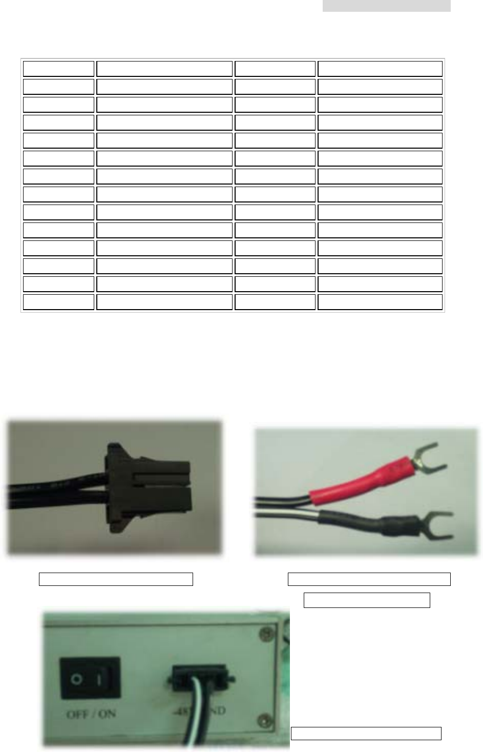
K. Grounding connection
L. Safety Wires 250V/2A
M. Power Switch
N. Power Input Port: -48V/1A DC
E1 Modem Power Terminal Connection to Power Terminal
( white black -;red + )
E1 Modem
with connection
5.8GHz PDH User’s Manual
11
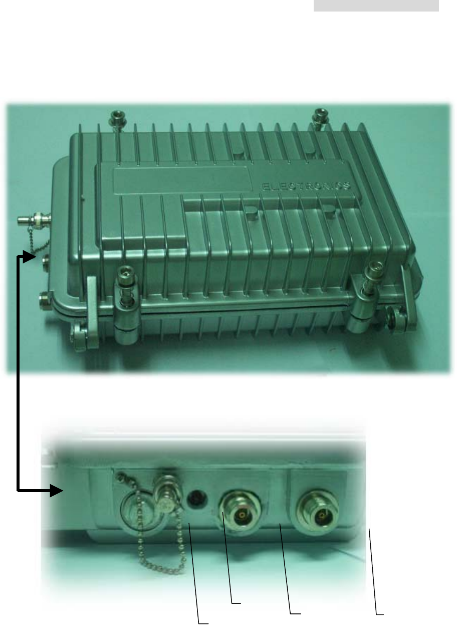
4.2 ODU
C
A
B
D

5.8GHz PDH User’s Manual
12
4.2.1 Function
A. RSSI Status: while setting up the equipments in longer distance range, in order to
conveniently adjust the antenna, we can switch on the BNC 50ohm terminal’s
resistance rotator. Use a 3in1 use voltmeter to measure the RSSI voltage and
potential. Please refer to the table given below. Higher the voltage, better the
antenna’s elevation.
B. Power Indicator (LED): ODU power indicator light. When all the connecting cables
are well connected, switch ON the IDU Power. Under normal working conditions, the
ODU’s LED display green light. LED is red if there is no connection at all.
C. Antenna Port: after properly fixing up the Antenna, use a moderate length N-Type
connector’s cable of 50ohm to connect to this port.
D. IF Port: this connection port and IDU-IF are connected by coaxial cable. The
maximum length of N-Type connector’s RG-5 cable is 100M. The maximum length of
N-Type connector’s RG-8 cable is 300M. The transmitting contents include transmit
310MHz, receiver 70MHz, monitor signal 11.0592MHz and DC -48V/1A。
※ After cable connection, please entwine waterproof tape at the connection point of the
ODU edges at the C and D port. This prevents rain or humidity from the equipment.
5.8GHz PDH User’s Manual
13
4.3 Data Transmission Port Guide
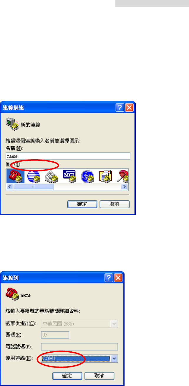
A. Click Start Æ Programs Æ Accessories Æ Communications Æ HyperTerminal to open
the HyperTerminal folder.
B. Enter a name in the Name blank, then press OK or in the HyperTerminal folder,
double-click on the HyperTerm icon to display the Connection Description window.
Fig.1
C. In the Connect To window, select the Direct to Com1 option in the Connect Using field.
Click on the OK button to open the Connect To window and to display the COM1
Properties window.
Fig.2
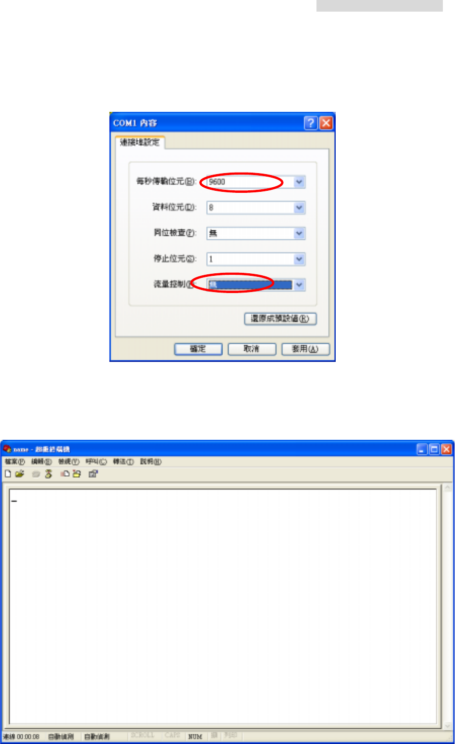
D. In the COM1 Properties window, select the following options:
5.8GHz PDH User’s Manual
14
E. Click on the OK button to open the StandardConfig--HyperTerminal application
window.
Fig.3
At this point, the HyperTerminal window provides monitor mode access to the terminal
concentrator. Please refer to WindowsXX User’s Manual.
5.8GHz PDH User’s Manual
10
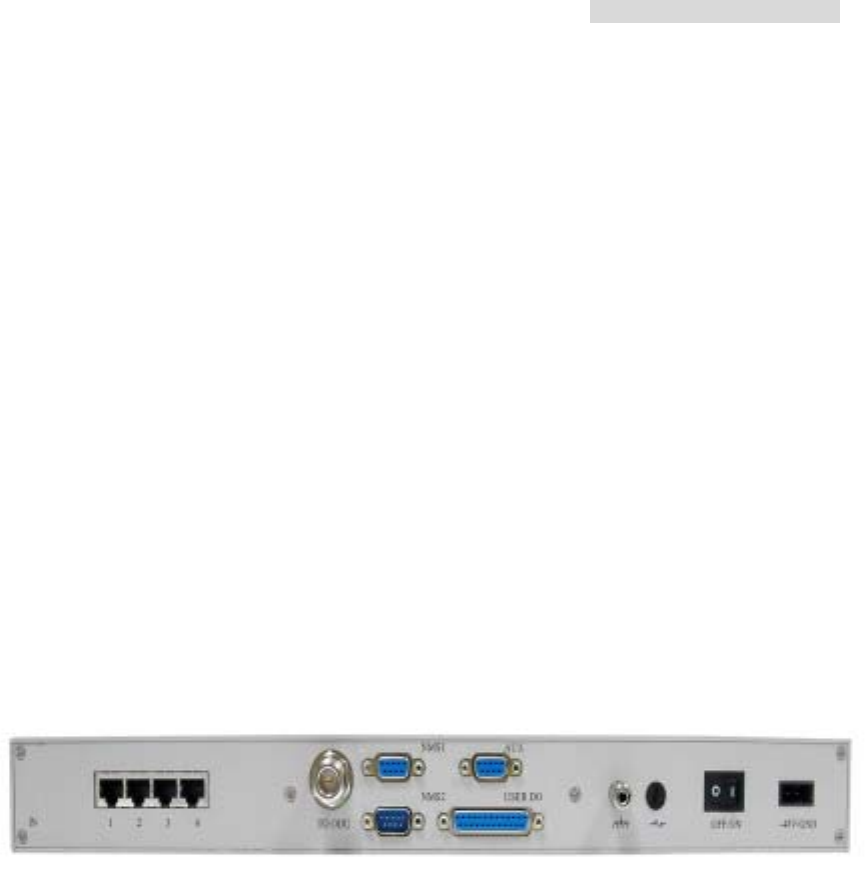
5. Interface
5.1 Rear panel
E1 interface may be of 75ΩBNC interface or 120ΩRJ-45 interface. User’s can flexibly
choose between these two.
Beside the standard E1 interface, the equipment also provide V.11, V.28, service, monitor,
computer signal communicating data port, loopback test port, etc. This provides the
subscribers to conveniently fully monitor the controlling room through this equipment. For
instance, from the central controlling room, we can get the information regarding the
temperature of the mounting machine, room temperature, fire alarm, power supply, etc.
and also from the central computer, we can monitor different functions such as light
switches, oil switches etc. This makes the realization of an overall intelligent management
of an unguarded station possible. This equipment has 8 input modes that is optically
isolated, plus 4 power relay output mode.
5.2 Front panel
5.2.1 Public telephone
Public telephone plays a significant role in this kind of communication or in areas with one
and only communication means as in microwave equipment’s application in mountainous
areas and underdeveloped areas. Other than possessing the function of selective calling,
entire calling etc. it also has the following most distinguishing features: whole tone service
like dial tone, engage tone, out-of-order tone etc. Users do not feel much difference in
using public phone from local call center service because it is very user-friendly and fits all
the demands of different users. Network management software is used to set up the public
telephone numbers from the local station.
Dial tone: When dialing from the local station, you’ll hear the same dial tone as any general
telephones
Engage tone: The repeating ring tone is 2±0.2s ring and 4±0.4s break
Ring tone: Same as the engage tone

5.8GHz PDH User’s Manual
11
Out-of-order tone: When there is an out-of-order service or lost of signal service, it will ring
the out-of-order tone at 500±50ms, 230ms±70ms and then break
connection
Busy tone: Continue to redial at an exchange of 500ms±50ms
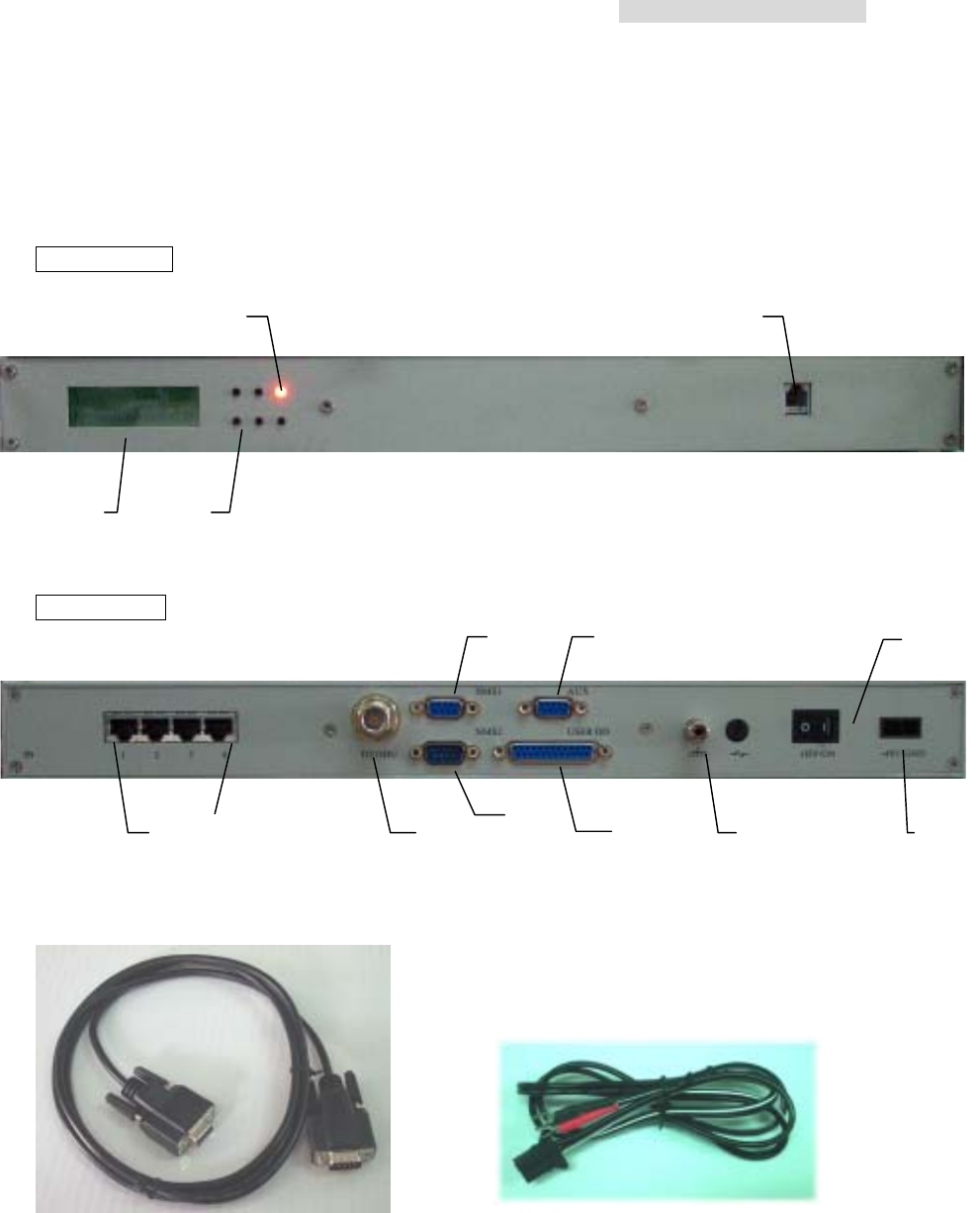
5.2.2 Definition of the IDU LCD Panel keys
ESC ALT
Left Right OK
For the LCD to fully display the system’s status and perform those simple set up operations,
try to make use of the above-mentioned five function keys to carry out the operations.
LCD displays the contents and different set-up entries. As described below, please apply
as mentioned.
IDU LCD Display
ESC = exit
ALT =
switch
functions
Left = left arrow
Right = right arrow
OK = confirm
5.8GHz PDH User’s Manual
12
I/O: Temp 4E1
R/T: Level BER
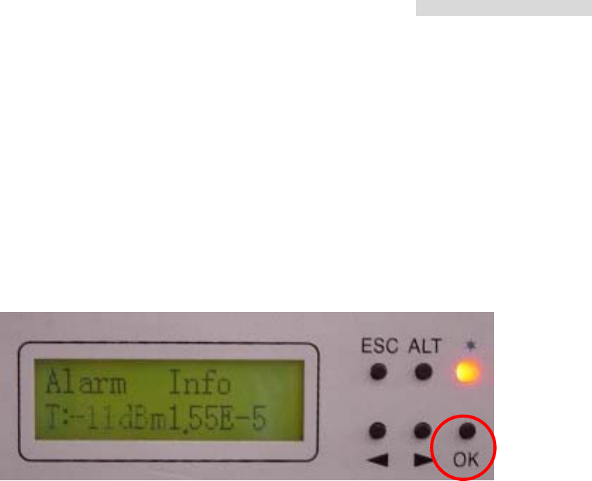
Alarm Info
R/T: Level BER
Not Alarm Alarm
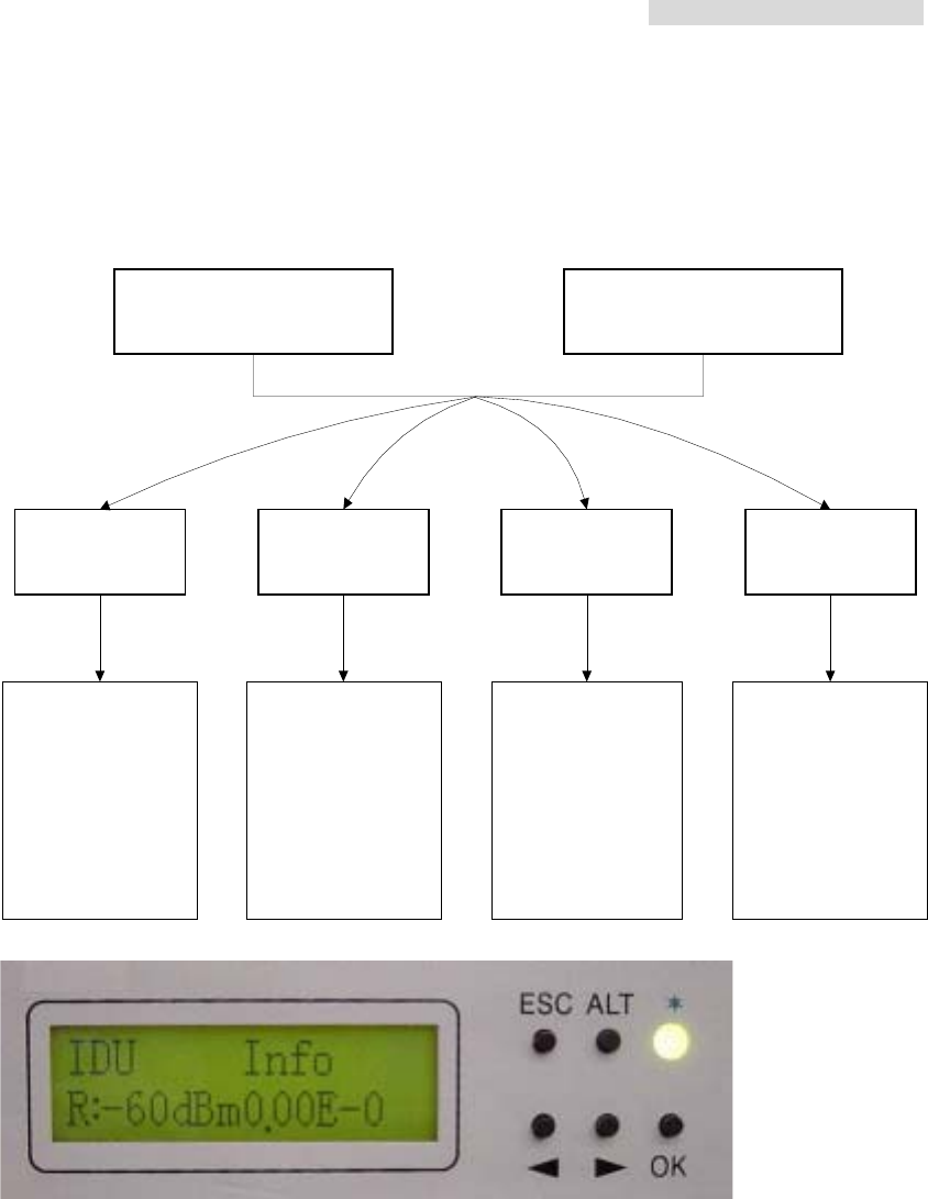
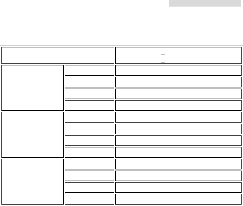
IDU LCD Display Status
IDU Info ODU Info TEST Item Remote Info
1.Local ID: n
2.DSC No.: n
3.IDU: nE1
4.Code: AMI/HDB3
5.ATPC: E/D
6.EXP_RSL: n dBm
7.I-Temp: n
℃
8.Buzzer: On/Off
1.RF CH/Freq
2.TxL_Set: n dBm
3.Tx-Mute: on/off
4.O-Temp: n
℃
1.T12_Loc-Loop: E/D
2.T12_Rem-Loop: E/D
3.T12_PRBS:
4.Error_ADD:
5.Ber_Clear:
6.Acc_Error:
7.IF-Loop: E/D
8.RF-Loop:E/D
9.Close-Test
1.Local ID: n
2.Far-end:
Alarm/OK/Loss
3.R-Status:
Test/Normal/Loss
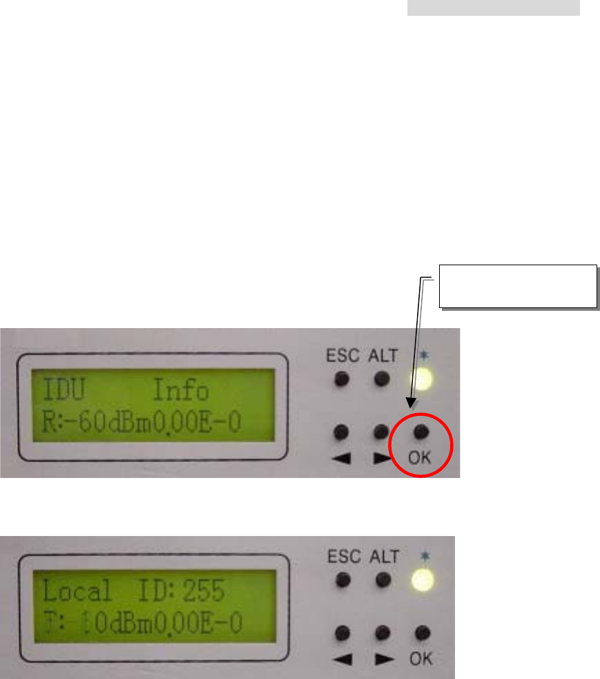
Under normal condition (no alarm), the LCD displays as below:
1. First line of the LCD display - On the right hand side, in every alternate 1~2 seconds, it
displays the I-Temp: xx.x stands for IDU temperature. O-Temp: xx.x stands for ODU
temperature. On the left hand side, 4E1 stands for the activity measure.
2. Second line of the LCD display - On the right hand side, in every alternate 1~2 seconds,
it displays the R: xxx stands for the online receiving power in real-time. T: xxx stands for
the online transmitting power in real-time. On the right hand side, it displays the
bit-error rate (BER).
Bit Error Rate (BER): The conversion formula for accumulated bit errors is
BER = (n/EN*S).
5.8GHz PDH User’s Manual
13
where, n = number of times of bit error;
EN = rate of the equipment, E1’s rate is 2.048M;S = working time ( in seconds).
For example:
Present bit error times is 3, working time is 2 minutes and system interface is E1
BER = (3 / (2.048 * 106 * 2 * 60)) = 1.22 E-8
Present bit error times is 1000000, working time is 4 minutes and system interface is E1
BER = (566 / (2.048 * 106 * 4 * 60 * 60)) = 3.39 E-5
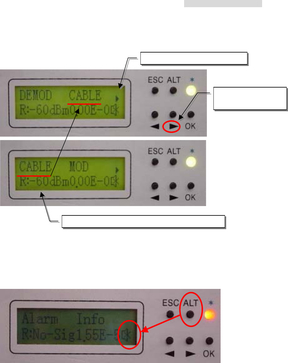
Under warning/alarming condition, the LCD displays as below:
Now press the OK button of the panel. It will display the alarm message. Press the
Right/Left button of the panel. The LCD displays the present alarm/warning message.
5.8GHz PDH User’s Manual
13
For example:
Whenever there is an alarm, the LCD back light will light for 2 mins. and the beeper sounds
goes off. Other than removing the alarm status or switching off the beeper status, we can
also switch off the beeper by pressing the ALT button. To switch on the beeper, please
enter the IDU Info/Buzzer: ON/OFF.
1. Message in the next page
2. Press this button to
read the next page
3. The first line of the LCD shifts towards the left
5.8GHz PDH User’s Manual
14
5.3 LCD definition & Operation:
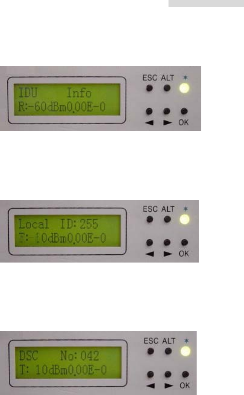
IDU Info
A1. Local ID:
Display the local equipment’s address. In the same link route system, there can
be a maximum connection of 255 equipments. NMS software is used for the
equipment’s initial set-up. This function is used for checking the present local end
equipment’s address.
A2. DSC No.: n
Display the local equipment’s service telephone number. In the same link route
system, there can be a maximum connection of 255 service telephone. NMS
software is used for the service telephone’s initial set-up. This function is used for
checking the present service telephone number.
5.8GHz PDH User’s Manual
15
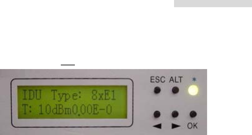
A3. IDU: n*E1
Display the number of E1 equipments. If it displays 8*E1, it means that the
equipment has eight E1 interface.
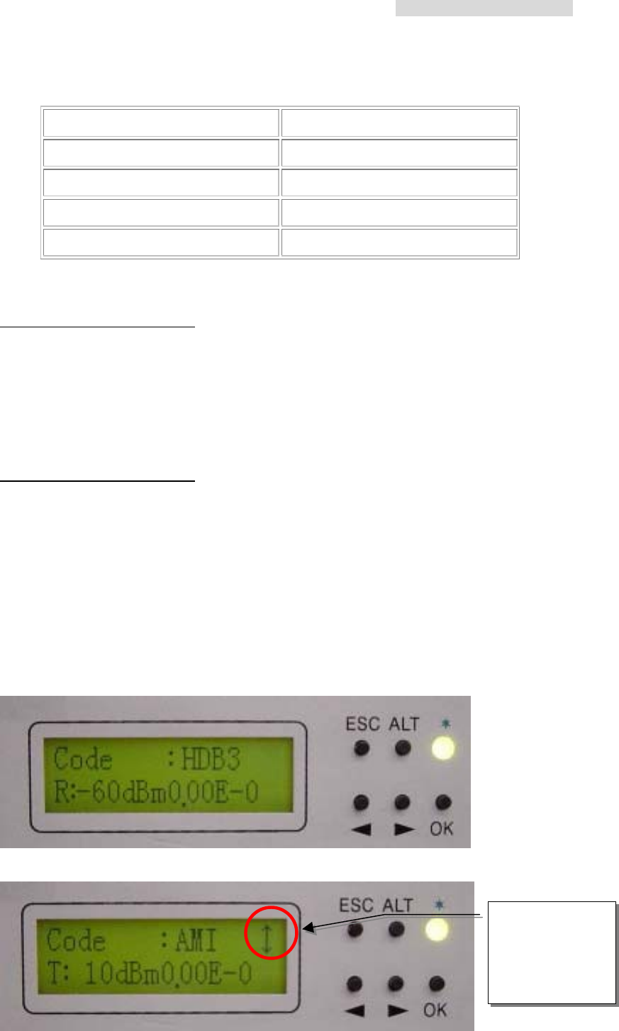
A4. Code: AMI/HDB3
Display the local end’s IDU dispatch model number. After pressing the OK button,
use the Right/Left button to choose the model number. At present, you may select
either of the two numbers: AMI or HDB3.
AMI:
AMI (Alternate Mark Inversion) is a synchronous clock encoding technique which uses
bipolar pulses to represent logical 1 value. A logical 0 is represented by no symbol
and a logical 1 by pulses of alternating polarity.
Example of AMI encoding
The pattern of bits " 1 0 0 0 0 1 1 0 " encodes to "+ 0 0 0 0 - +"
HDB3:
HDB3 (High Density Bipolar Order 3 Encoding) is based on Alternate Mark Inversion
(AMI), but extends this by inserting violation codes whenever there is a run of 4 or
more 0's. This and similar (more complex) codes have replaced AMI in modern
distribution networks. The purpose of this is to prevent long runs of 0's in the data
stream, sometimes called a "run length limited" code. Encode any pattern of more
than four bits as B00V, where B is a balancing pulse. The value of B is assigned
as + or - , so as to make alternate "V"s of opposite polarity. The receiver removes
all Violation pulses, but in addition a violation preceded by two zeros and a pulse
is treated as the "BOOV" pattern and both the violation and balancing pulse are
removed from the received bit stream. This restores the original bit stream.
5.8GHz PDH User’s Manual
16
Summary of HDB3 encoding rules
Transmitted Data HDB3 Encoded Pattern
0 0
1 Alternate Mark Inversion (AMI)
0000 000V (three 0's and a violation)
0000 0000 B00V B00V
HDB3 is one of CCITT’s recommended uses.
Example 1 of HDB3 encoding
The pattern of bits
" 1 0 0 0 0 1 1 0 "
Encoded in HDB3 is
" + 0 0 0 V - + 0 "
(the corresponding encoding using AMI is " + 0 0 0 0 - + ")..
Example 2 of HDB3 encoding
The pattern of bits
" 1 0 1 0 0 0 0 0 1 1 0 0 0 0 1 1 0 0 0 0 0 0 "
Encoded in HDB3 is " + 0 - 0 0 0 V 0 + - B 0 0 V - + B 0 0 V 0 0 " which is:
" + 0 - 0 0 0 - 0 + - + 0 0 + - + - 0 0 - 0 0 "
(the corresponding encoding using AMI is " + 0 - 0 0 0 0 0 + - 0 0 0 0- + 0 0 0 0 0 0 ").
For example: modifying E1 transmitted HDB3 code to AMI code
1. Enter IDU Info/Code: sub-menu. Press OK.
2. Press the Right/Left button to change HDB3 to AMI. Press OK.
This sign shows
you may use the
Right/Left arrow
to select the
functions
5.8GHz PDH User’s Manual
17
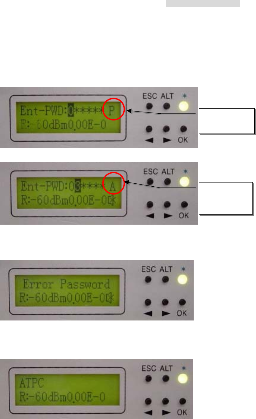
3. Enter the password verification. Enter the 6-digits system password. Use ALT to
change to different functions.
P = Place
A = Adjust
Press OK.
※ For the password, enter as described in NMS guide.
4. Error Password is display on the entering the wrong password. It will not save the
wrong password. This will be display for 5~10sec. and then return to the main
function display.
※ Use NMS to setup the password. LCD does not allow password correction.
A5. ATPC: En/Dis:(Retain)
P mode,
use the Right/Left
button
A mode, (0~9)
digits, use the
Right/Left
button
5.8GHz PDH User’s Manual
18
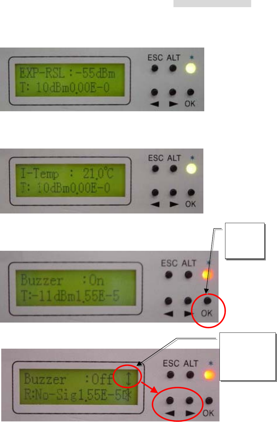
A6. EXP_RSL: - n dBm:(Retain)
A7. I-Temp: n
Display the local end’s ODU working temperature.
A8. Buzzer: ON/OFF
Display the buzzer switch to ON/OFF.
Press OK
to enter
the setup
function
This sign shows
you may use the
Right/Left arrow
to select the
function OFF.
Press OK
5.8GHz PDH User’s Manual
19
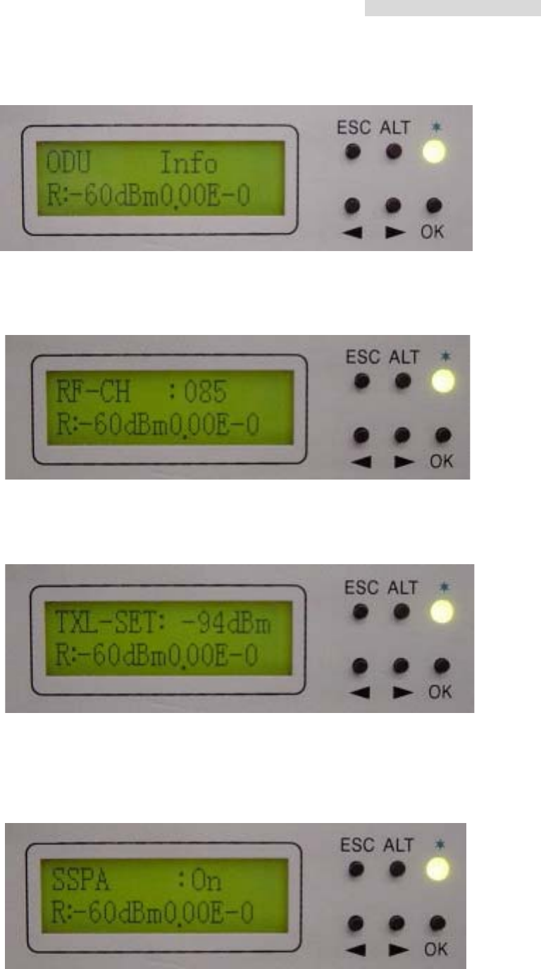
ODU Info
B1. RF CH/Freq
Display the present ODU RF channel and frequency range.
B2. TxL_Set: n dBm
Display the transmit power, n = 5~22dBm.
B3. Tx-Mute: ON/OFF
To set the PA to ON/OFF. Press the OK button after selection. Use the Right/Left
button to select ON/OFF, then press OK.
5.8GHz PDH User’s Manual
20
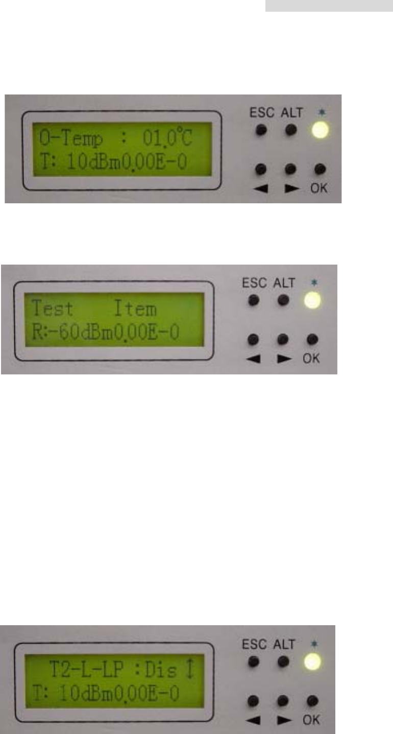
B4. O-Temp: n
Display the local end’s ODU working temperature.
TEST Item
※ Loopback mode. Note: system allows only one kind of loopback at a time
C1. Tn_Loc -Loop: En/Dis
Perform loopback test in the local end for the convenience of testing the local end
equipment’s stability. Use the Right/Left button to select the local E1 interface of
T1~Tn subsidiary route. Press the OK button. The Right/Left button is also used
for selecting En/Dis. En = enable the execution of local loopback test. This
function can also be used with external connection to E1 transmission for testing
any malfunction in the E1 interface.
※ Note: This function can not be used with the PRBS provided for testing.
For example:
i) To set up the T2 of E1 to local loopback mode, enter \TEST Item\T2-L-LP,
press OK.
5.8GHz PDH User’s Manual
21
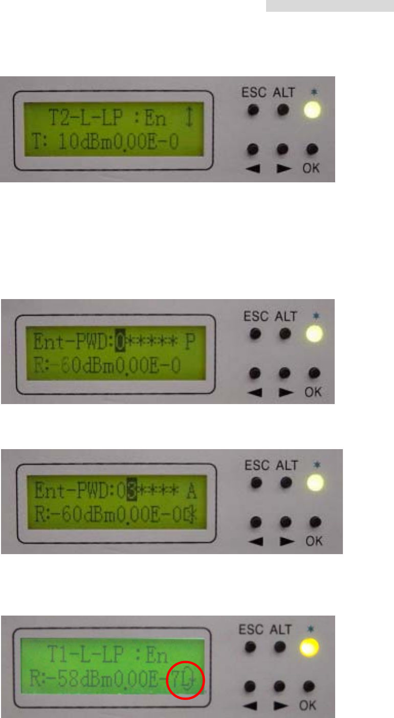
ii) Use the Right/Left button to change Dis (Disable) to En (Enable). Press OK.
iii) It will display the enter password verification. Enter the system 6-digits
password. Use ALT to switch between the different functions.
P (Place): shifting/placing the position using the Right/Left arrow
A (Adjust): adjusting the digits from 0~9 using the Right/Left arrow.
Press OK to complete the settings.
※ For the password, enter as described in NMS guide
Local end: While tributary 1 is in local loopback mode, the right bottom side
displays an “L”. The LED displays an orange glow.
5.8GHz PDH User’s Manual
22
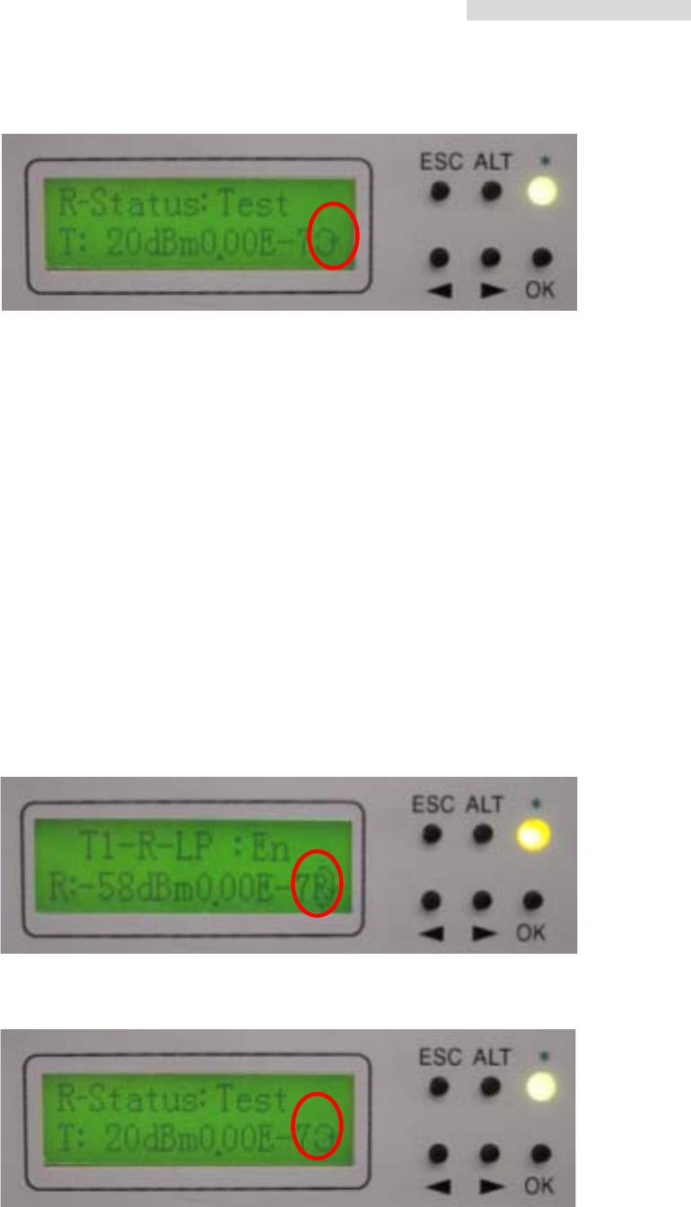
Remote end: The right bottom side displays a loopback sign.
C2. Tn_ Rem -Loop: En/Dis
Perform loopback test in the remote end for the convenience of testing the local
end equipment’s stability. Use the Right/Left button to select the local E1 interface
of T1~Tn subsidiary route. Press the OK button. The Right/Left button is also used
for selecting En/Dis. En = enable the execution of local loopback test. This
function can be co-operated with the IDU PRBS (C3) function for the loopback test,
as well as external connection with E1 equipments for transmission test.
※ Note: while executing PRBS, the local and remote equipment will display both the
local and remote’s accumulated bit error.
Local end: While tributary 1 is in local loopback mode, the right bottom side
displays an “R”. The LED displays an orange glow.
Remote end: The right bottom side displays a loopback sign.
5.8GHz PDH User’s Manual
23
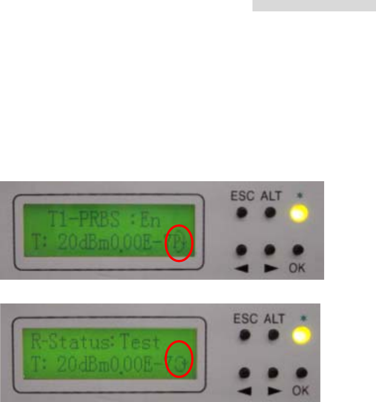
C3. Tn_PRBS12: En/Dis
Use Pseudo Random Code to test the E1 signal transmission. Along with the
remote loopback, IF loopback, normal link route equipment and stability of testing
equipments, Press the OK button. Use the Right/Left button to select
Enable/Disable, and then press OK. On using this function, the LCD will display all
the accumulated BER.

5.8GHz PDH User’s Manual
24
Pseudo-Random Bit Sequence (PRBS):
Random noise was first regarded as an element that damages the quality and quantity
of communicative signals in communication technology. The random noise in signal
channels often distorts the simulated signal produced or bit error to appear upon the
demodulation of digital signals. At the same time, it is also one of the elements that limit the
channel capacity. Consequently, human’s early attempt was to remove or lessen all the
pseudo noise in the communication system. Nonetheless, some of them decided to obtain
all these pseudo noise. For example, communicative equipments or systems testing in
laboratory require an addition of certain noise. So it is necessary to produce/obtain noise
here.
In the late 1940s, along with the communication theory, Claude Shannon pointed out
that under certain conditions, for the most effective communications, must adopt signals
containing the statistical property of white noise. Besides, in order to achieve
communications of high reliability and privacy, we must use random noise. However, the
biggest difficulty faced in using random noise is that it is not easy to repeatedly produced
and processed. Until the 60’s, the pseudo random noise came about and solve all these
problems.
Pseudo random noise poses statistical property similar to random noise. At the same
time, it can be repeatedly produced and processed easily. It has increasingly been
extensively use practically because it poses the advantages of random noise and none of
its disadvantages. In today’s world, it has been extensively used in digital circuit produced
periodic series (after filtering). In the future, this shall be called the periodic series or the
random series.
Pseudo random sequences are generated using a binary shift register with taps that
are modulo-2 added together and fed back to the register's input. The name commonly
5.8GHz PDH User’s Manual
25
used for this simple circuit is linear feedback shift register, or LFSR. Another type is known
as the Non-Linear Feedback Shift Registers. Only certain combinations of feedback taps
will result in maximal-length sequences, called m-sequences. These are the longest
sequences possible given a specific shift register size, and they have many desirable
properties. If the register size is m stages, the length of the m-sequence will be 2m-1.
Nowadays, the equipments used are mostly PRBS of m-sequence: x15 + x + 1, 100003.
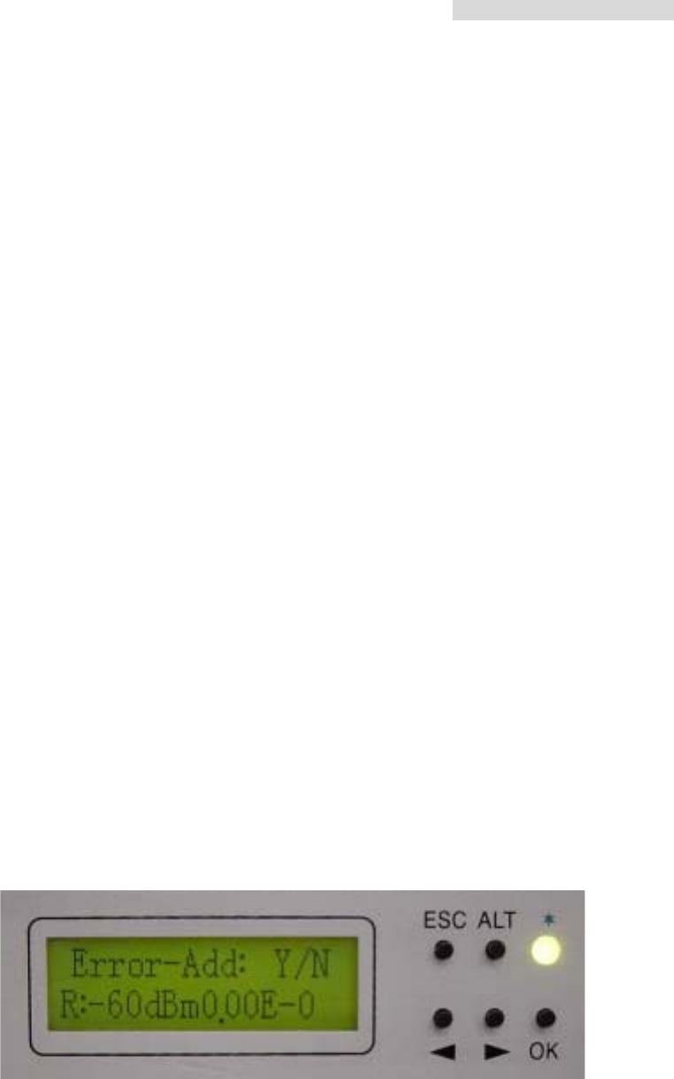
C4. Error_ADD: ?
Bit error is produced each time the bit error transmission test is started. This
function is for the convenience of online bit error test and for displaying normal
loopback test. The bit error can also be added manually. Press the OK button to
add one times of bit error.
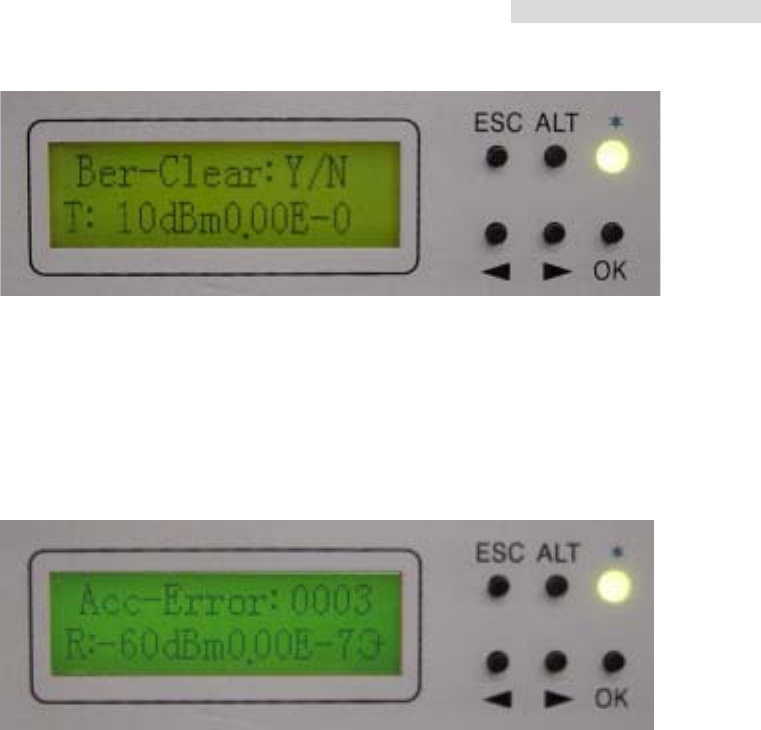
C5. Ber_Clear: ?
Clear all accumulated bit error on starting the bit error transmission test: Press the
OK button.
5.8GHz PDH User’s Manual
26
C6. Acc_Ber: num E -n
Display all the up-to-date accumulated bit error on starting the bit error
transmission test.
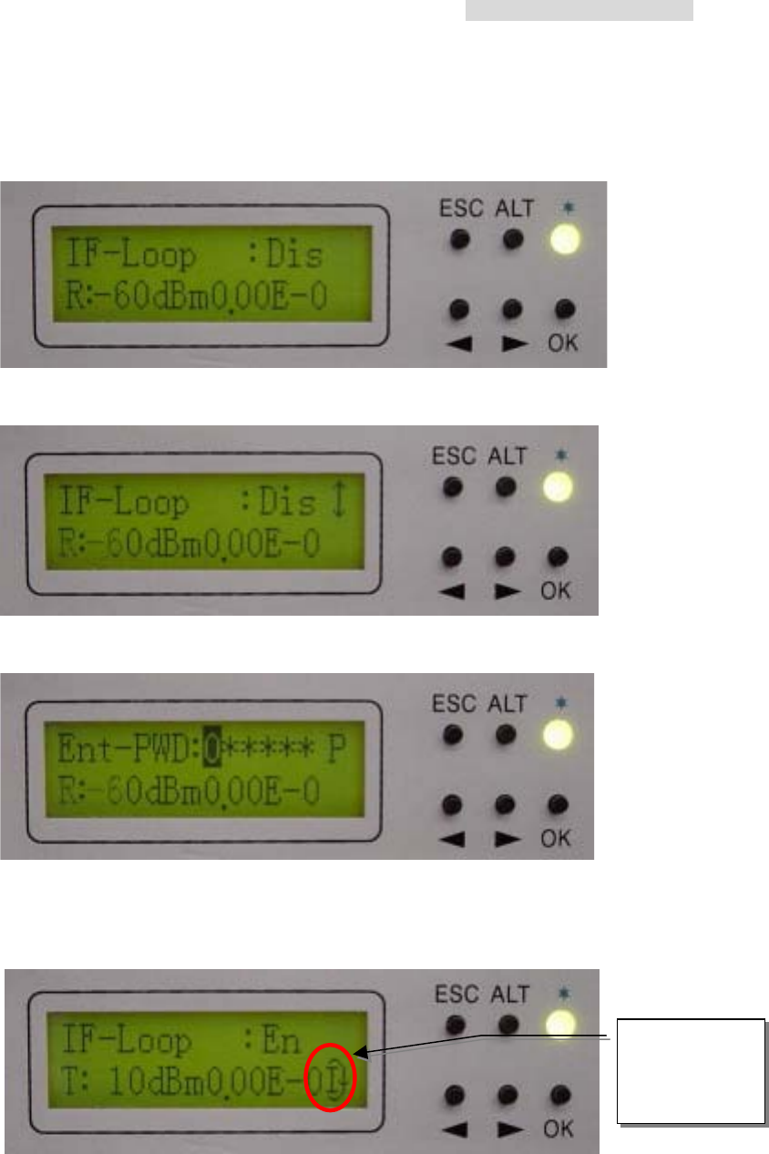
C7. IF-Loop: En/Dis
Perform loopback test from IF interface for the convenience of testing the IDU’s
stability. Press the OK button. Use the Right/Left button for selecting either En/Dis
(En: Enable / Dis: Disable). Press the OK button again to start the execution of this
function. This function can be co-operated with the IDU PRBS (C3) function for the
loopback test, as well as external connection with E1 equipments for transmission
test.
5.8GHz PDH User’s Manual
27
For example:
i) Enter \TEST Item\IF-Loop: En/Dis. Press OK.
ii) Use the Right/Left button to switch Dis to En. Press OK.
iii) Enter password using the same method as in C1-Tn_Loc-loop: En/Dis.
While IF-Loop is in execution, the right bottom side will display an “I”. The LED
display an orange glow.
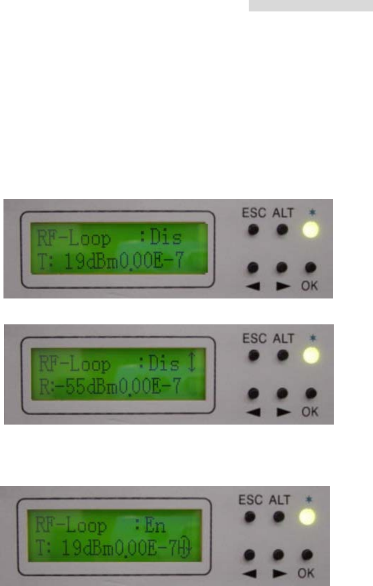
C8. RF -Loop: En/Dis
Perform loopback test from RF interface for the convenience of testing the IDU
and ODU stability. Press the OK button. Use the Right/Left button for selecting
This sign
display the
IF-Loo
p
under
5.8GHz PDH User’s Manual
28
either En/Dis (En: Enable / Dis: Disable). Press the OK button again to start the
execution of this function. This function can be co-operated with the IDU PRBS
(C3) function for the loopback test, as well as external connection with E1
equipments for transmission test.
For example:
i) Enter \TEST Item\RF-Loop: En/Dis. Press OK.
ii) Use the Right/Left button to switch Dis to En. Press OK.
iii) While RF-Loop is in execution, the right bottom side will display an “H”. The
LED displays an orange glow.
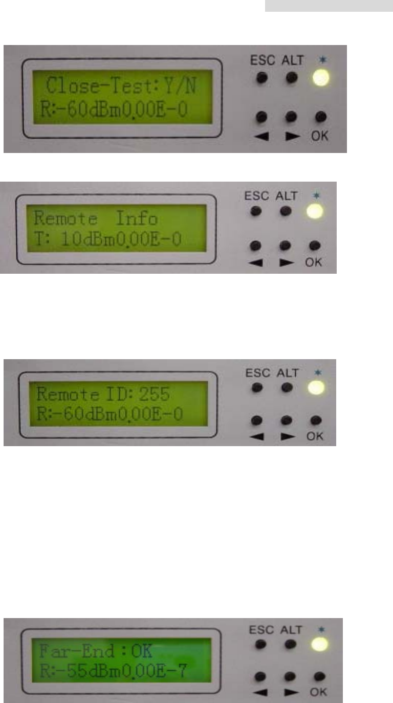
C9. Close-Test: Y/N
Close all testing procedure.
5.8GHz PDH User’s Manual
29
Remote Info
D1. Local ID: n
Display the address of the remote equipment; n=1~255. It is possible to check the
remote end’s present ID address.
D2. Far-end: Alarm/OK/Loss
Display the connection status of remote end equipments. It is used as a function of
signal monitor for the determination of its source.
Alarm: remote monitor function fails
OK: in connection
Loss: R_MON signal loss
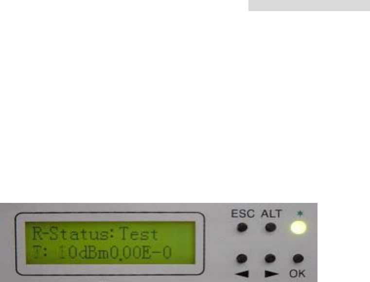
D3. R-Status: Test/Normal/Loss
5.8GHz PDH User’s Manual
30
Display the system present working status. It is possible to check the base station
at the opposite end as well as the status of whether there is any online test is
carried out upon the execution of this function.
Test: remote end in testing status
Normal: normal working condition
Loss: R-Status signal loss

5.8GHz PDH User’s Manual
31
6. Environmental Condition
6.1 Cable
Intermediate Frequency, IF Cable: RG-8 ≤200m
Radio Frequency, RF Cable: Insertion Loss ≤1dB
6.2 Temperature
Radio Frequency, RF temperature: -30 to +60
6.3 Voltage and DC power consumption
Voltage: -36∼-78Vdc
DC power consumption: <20W
6.4 Humidity
Relative humidity: 10%∼95%
5.8GHz PDH User’s Manual
32
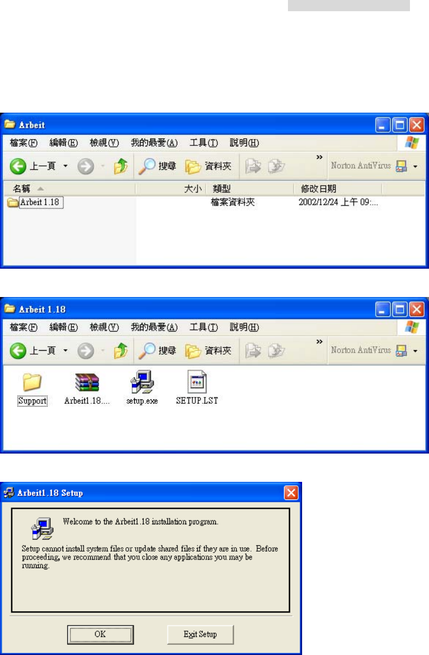
7. Software Installation
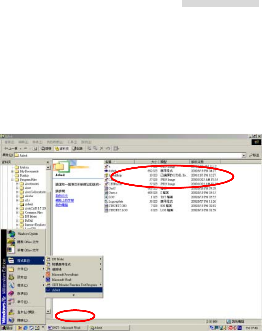
a) Click Open the CD-ROM folder containing the monitor software. The following window
appears:
b) Click Open the folder “Arbeit v1.xx”. Click twice to execute the “setup.exe” file.
c) The setup welcome window will appear.
d) Click the “OK” button. Install the software to any desired folder by clicking on the
“Change Directory” button.
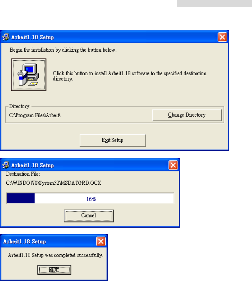
5.8GHz PDH User’s Manual
33
f) Click the button “確定” after the successful completion of software installation.
5.8GHz PDH User’s Manual
34
8. Arbeit NMS software
8.1 Open “Arbeit”
There are two ways to open the program Arbeit:
i. Click on the StartÆ Programs Æ Arbeit.
ii. Open File Manager Æ Program Files Æ Arbeit Æ Arbeit.exe.
5.8GHz PDH User’s Manual
35
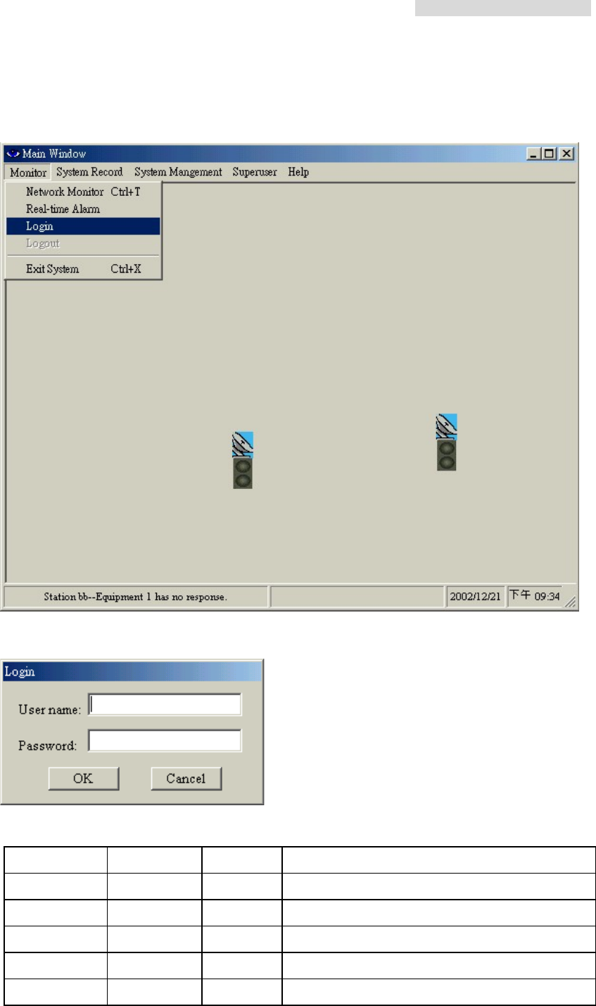
8.2 Login
After executing the program Arbeit, Click on the menu bar “Monitor”. Select “Login”
In the Login window, please enter “User name” and “Password”.
The system already has some pre-set user name and password, which are given below:
# User name Password Function
Configuration initialize initialize Initial setting for single machine
User dd 2 General users and station maintenance users
Administrator system system Administrator, can add new users
System Test loopback loopback System test
Superuser andy andy Superuser, can use all the functions
5.8GHz PDH User’s Manual
36
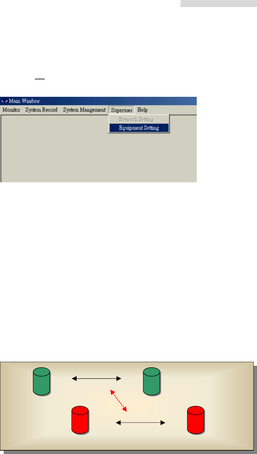
8.3 Initialization
Login the local end initialization mode as User Name:initialize Password:initialize. In the
Main Window, select Superuser Æ Equipment Setting. Another initialization window will
appear with five different working mode: IDU Setting 、ODU Setting、Alarm Setting、Cross
Connecting、User I/O Setting.
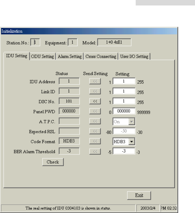
8.3.1 IDU Setting
While setting the below functions, first modify or add any new settings, then press Send
Setting to save it in the Status. It is also saved in the IDU equipment. The setting will now
be shown on the window Status. Press Check to check any settings made. It will read all
the data from the IDU. Exit the window if there are no error settings.
i. IDU Address: Each and every E1 modem in the network has its own unique IDU
Address for different purpose and ease of setting. While setting up the station, all
initialization must be done here first. If initialization is not set accordingly, it will not work
properly. As given the figures, we first enter “2” in IDU Address. Press Send Setting to
confirm.
ii. Link ID: Link ID might have similar equipment close by if it is kept in the same
environment. In order to prevent wrong connection, it is strongly advised to enter a
differentiating Link ID.
Check button: Read all the IDU setting and to check whether it has been written in.
Password Change button: Edit initial login and password.
Exit button: Exit and close the initialization mode window.
Link ID: 1
Link ID: 2
X no link
Station A Link ID: 2 Station B Link ID: 2
Station A Link ID: 1 Station B Link ID: 1
5.8GHz PDH User’s Manual
37
DSC No:Enter any number between 0~255 for digital service telephone number setting.
Note that the DSC number should be different from the Link ID. On the right side of the IDU
panel, there is a RJ-11 connector meant for analog telephone, which is used for all phone
connection in the route with the base station.
Panel PWD:This function is not open to all users owing to the fact that while setting the
IDU in the local end, some of the functions are still in process which will cause the full
breakdown of the machine. If necessary, enter the IDU password, which must only be 0~9
digits, ranging from 0~999999.
A.T.P.C:Automatic transmitting power control
Expected RSL:Automatic transmitting power control parameters
Code Format:IDU transmission encoding format AMI or HDB3
BER Alarm Threshold:BER alarm setting: E-5、E-4、E-3 etc.
Check:Check all the IDU setting data
Exit:Exit the initialization mode after all IDU setting.
5.8GHz PDH User’s Manual
38
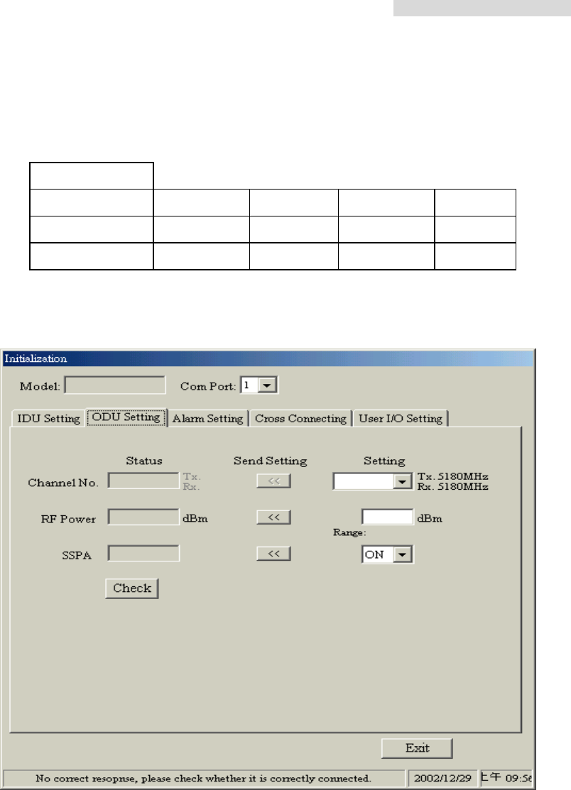
8.3.2 ODU Setting
Channel No:Set ODU RF transmitting and receiving power. The frequency channels used
are as follows:
4E1
1 5730.5 5737.5 5822.5 5829.5
2 5738.5 5745.5 5830.5 5837.5
3 5746.5 5753.5 5838.5 5845.5
Unit:MHz
RF Power:Set ODU transmitting power, range 22~5dBm。
SSPA:Switch ON/OFF the ODU power amplifier (PA On/Off)。
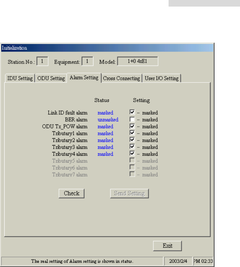
8.3.3 Alarm Setting
Under normal working condition, if the IDU goes into a critical state, the alarm will start
beeping. However, in some cases like if the administrator considers the Link ID
unimportant, s/he may tick “masked” and turn off all the alarm functions.
Link ID fault alarm – local station receives the wrong Link ID.
BER alarm – Bit error alarm
ODU Tx_POW alarm – ODU Output Power alarm
Tributary x loss alarm – IDU cannot find the tributary signal.
5.8GHz PDH User’s Manual
39
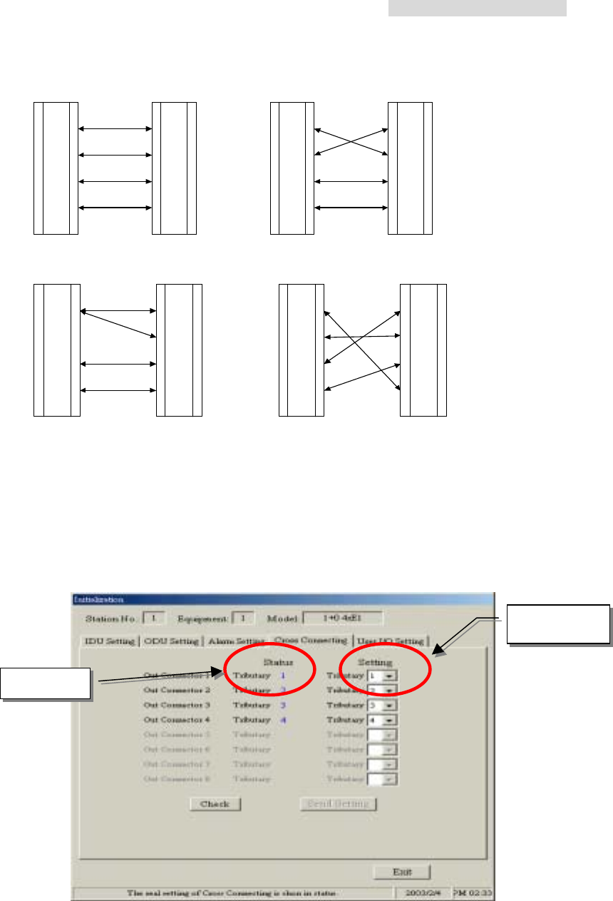
8.3.4 Cross Connecting
Under normal working condition, with the need of adjusting the controlling room channel,
the local and remote end E1 Interface have certain asymmetric variation. The following
diagram shows the 4E1 equipment cross connection between local end, IDU A, and
remote end, IDU B.
5.8GHz PDH User’s Manual
40
1
2
3
4
1
2
3
4
1
2
3
4
1
2
3
4
AB
ID U A IDU B IDU A IDU B
1
2
3
4
1
2
3
4
1
2
3
4
1
2
3
4
CD
ID U A ID U B ID U A ID U B
Fig. A Normal connection mode
Fig. B Local and remote port1 & port2 in cross connection mode and port3 & port4 in normal
connection mode
Fig. C Local port 1 connected to remote port1 & port 2. Local and remote port3 & port4 in
normal connection mode
Fig. D Local and remote port in cross connection mode between ports 1&4, 3&1 and 4&3
8.3.5 User I/O Setting
Besides the standard E1 interface, there are the environment monitor and control port. This
allows users to fully control the controlling room from the local end. For example: If there is
no manual control over the remote end, it is possible to have all the temperature, alarm,
Local end
Remote end
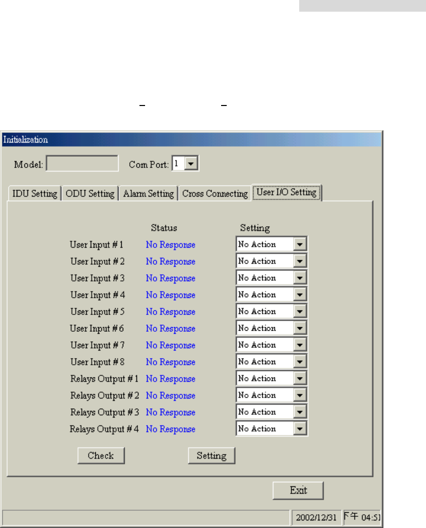
5.8GHz PDH User’s Manual
41
power supply etc. data from the central controlling computer. The central controlling
computer controls most of the functions as well which made knowledge management
possible. The equipment has 8 User Input and 4 Relay Output.
5.8GHz PDH User’s Manual
42
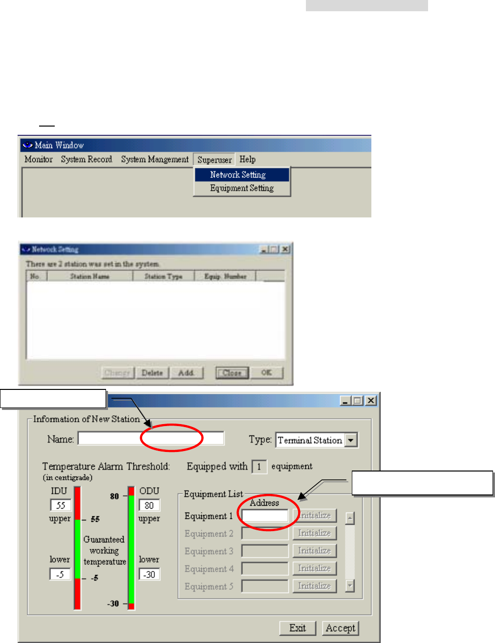
8.4 Superuser
Login the link route setting mode as User Name:superuser Password:8. In the Main
Window, select Superuser Æ Network Setting. Another initialization window will appear
with five different working mode: Change、Delete、Add.、Close、OK
Add. – First select Add. to add new station.
Press Accept after entering all the necessary information.
Enter equipment address
Enter station name
5.8GHz PDH User’s Manual
43
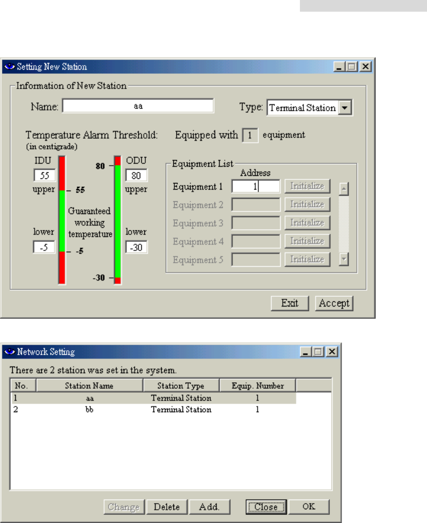
1. Enter “aa” in the Name and “1” in the Address dialog box.
Note: the station name must not exceed 30 characters or numbers.
2. Press “Add.” to enter the second data. Enter “bb” in the Name and “2” in the
Address dialog box.
Every station has its own address after the “Initialize” setting. First, select Add. , then
choose the corresponding Address. In the Station Name, enter a different name. It will be
displayed on the Monitor and on the IDU-LCD.
5.8GHz PDH User’s Manual
44
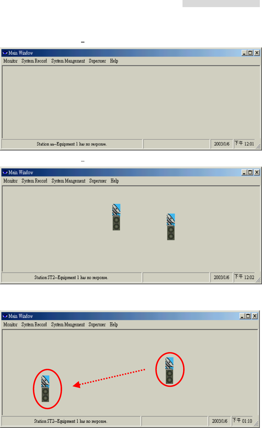
Arbeit Main Window, added 0 station:
Arbeit Main Window, added 2 new stations:
The stations position in the above diagram is a random result. Right click on the station and
move it without releasing the mouse and place it to any desired position.
5.8GHz PDH User’s Manual
45
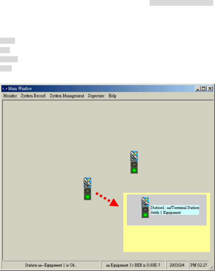
Under normal connection, the station icon will display its working status.
Green glow = normal connection
Red glow = connection, with warning alarm
Orange glow = test state
Grey glow = no connection
Move the mouse to the station icon;
it will display the station name and
address
5.8GHz PDH User’s Manual
46
Now let us introduce some other functions of the link route station setting:
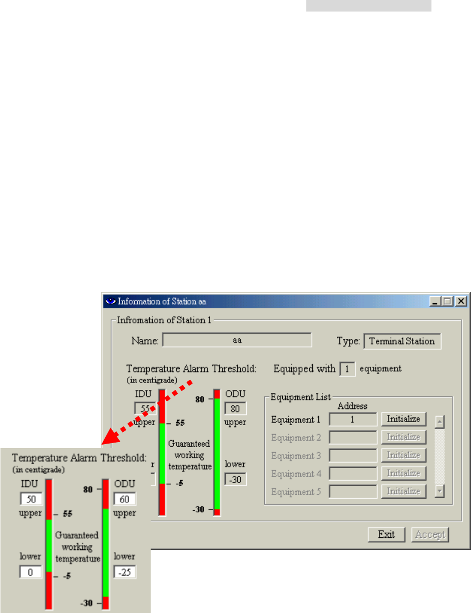
Alarm Temperature Threshold:
Set the IDU&ODU secondary alarm temperature range. Enter the desired
parameters in the upper and lower IDU& ODU temperature alarm threshold dialog box.
When the temperature is higher than or lower than this threshold, the system alarm will
start beeping. The system has its own Operating Temperature threshold as well. As shown
in the Station Setup window, the IDU upper and lower Temperature threshold is +50 and
-5 respectively and the ODU are +60° and -30° respectively. The threshold can be set
between these two upper and lower thresholds. The upper threshold must not be too low
and the lower threshold must not be too high, if it is NOT so, the alarm will go off every now
and then even if all the setting are correct.
Number
Automatically generate a number from 1~255 for the convenience of calculating the
number of stations.

5.8GHz PDH User’s Manual
47
Del.&Add.
The Del.&Add. button is used for adding or deleting any stations.
For modifying any stations data, select the particular station and modify its content. Press
OK after completing.
Terminal Station
Base station in a terminal end mode. The stations are in a point-to-point connection mode.
Center Station
Base station acts as the Center station. When there are more than two equipments in a
base station, please select this type of mode. We can use the IDU Net port function only if
we used it in Center Station mode. Using Arbeit, it is possible to see all the equipment’s
route in the station by concatenating all the monitoring information of the station. 每個
Base station can have NOT more than ten Center. Extended station link route can be a
maximum of 255. This mode can also be called the star topology station setting mode, as
illustrated in the following diagram:
Initialize
Stations link route initialization mode. This function can randomly change the route of the
stations provided it is in connection mode.
5.8GHz PDH User’s Manual
48
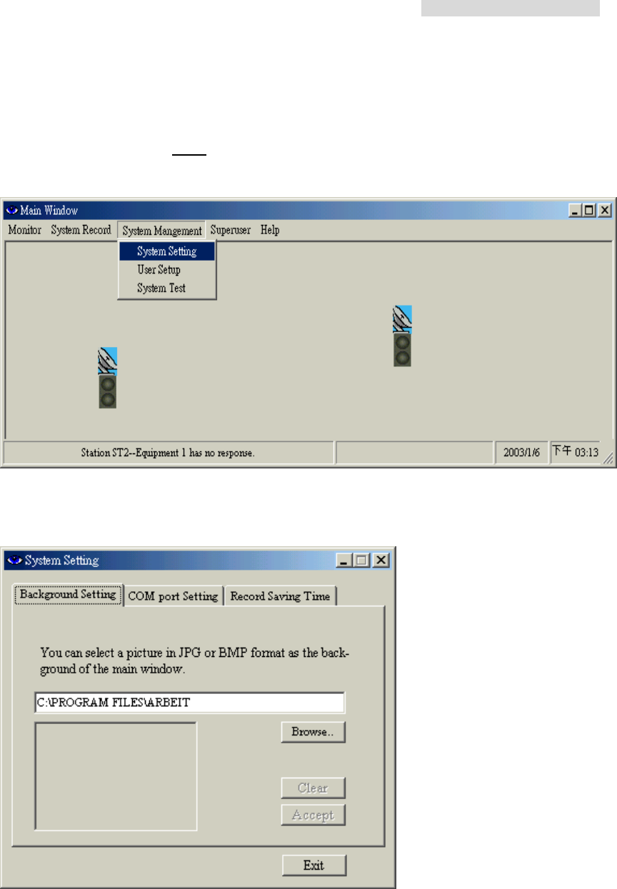
8.5 System Setting
In the Main Window, select System Management Æ System Setting. Another initialization
window will appear with three different working mode: Background Setting、COM Port
Setting、Record Saving Time.
8.5.1 Background Setting
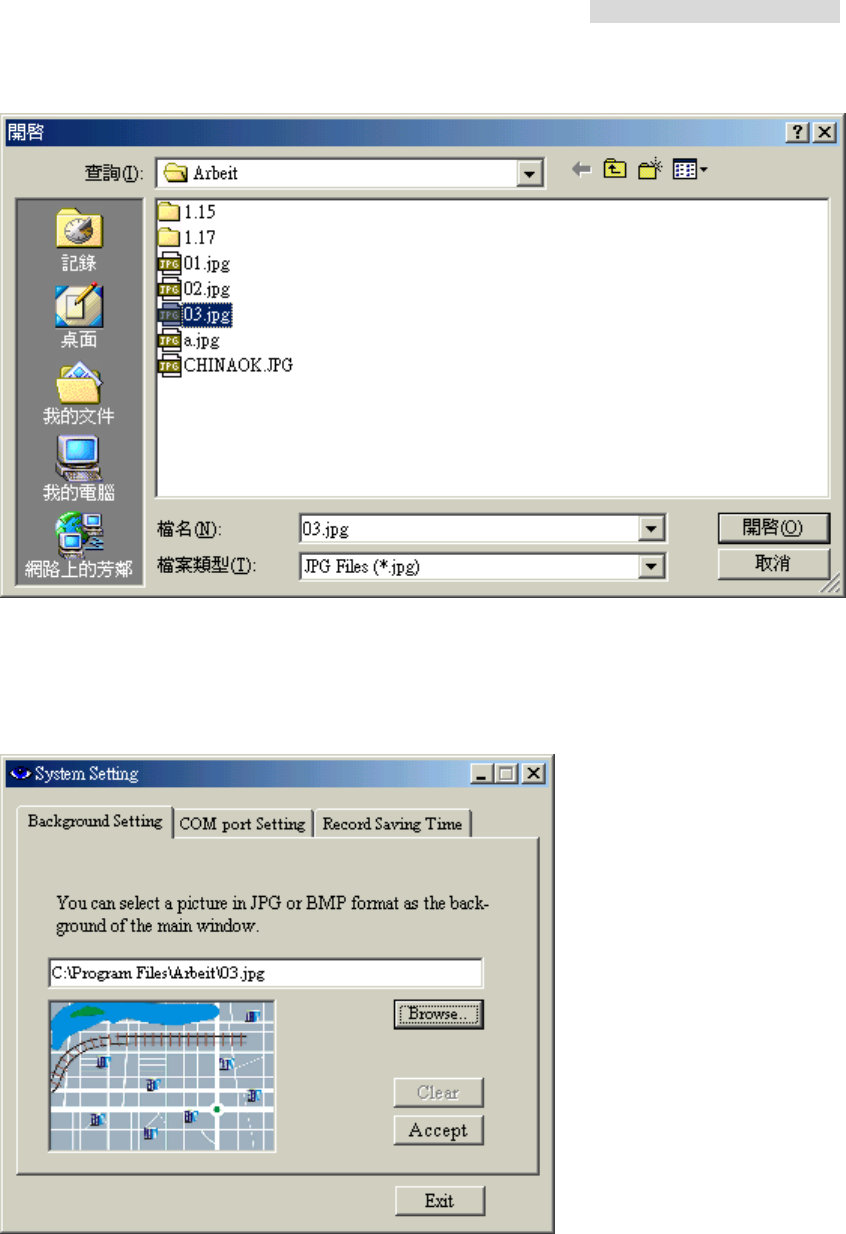
In System Setting, we use the Background Setting tab to edit the router map. For example:
street, building, station setting etc. Save the file in *JPEG format after editing. In Arbeit
folder, we can open the picture file again for the easy modification. In the following diagram,
for example, we open the 03.jpg file, it will show the following:
5.8GHz PDH User’s Manual
49
After opening the 03.jpg file, we see a preview of the picture file. Press Accept button to
use the picture file as the background setting of your desired route. Press Clear button to
remove the background setting.
5.8GHz PDH User’s Manual
50
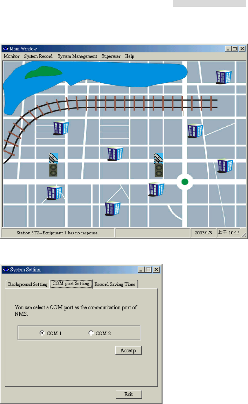
Example: Selected background setting
8.5.2 COM port Setting
In the COM port Setting tab, you can select a COM port as the communication port of NMS.
Press the Accept button after selection.
5.8GHz PDH User’s Manual
51
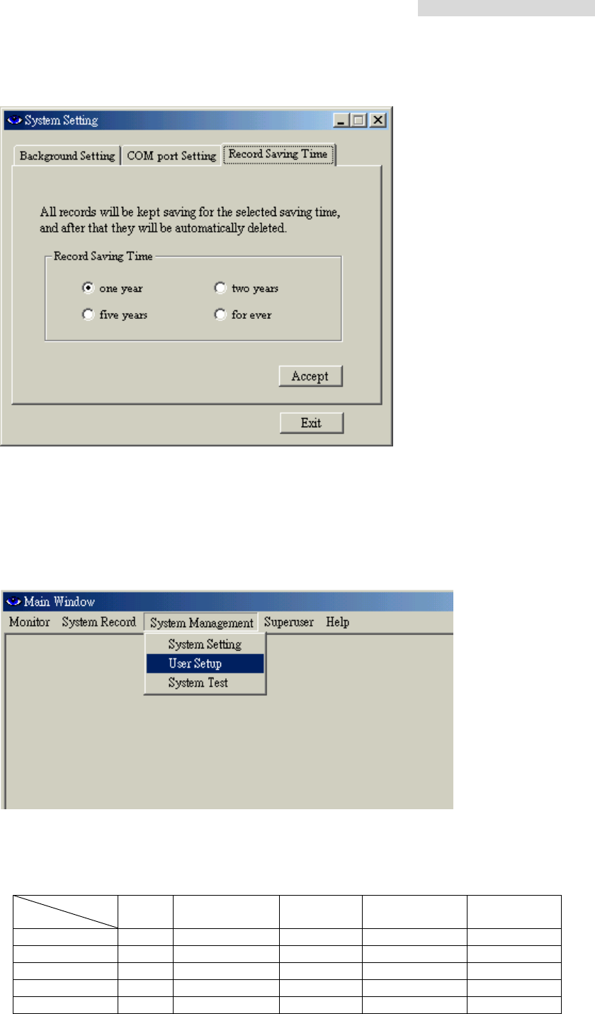
8.5.3 Record Saving Time
Select the saving time of the alarm records: 1/2, 1, 2, 3, or 5 years. Press the Accept button
after selection.
8.6 User Setup
In the Main Window, select System Management Æ User Setup.
Note: The higher the grade (with different login account), the more the function is allowed.
Superuser is the highest grade. The following table shows the function allowed for each
grade:
Grade
Login User Administrator
System
Tes t Configuration Superuser
Superuser ; ; ; ; ;
Administrator ; ;
System Test ;
Configuration ;
User ;
5.8GHz PDH User’s Manual
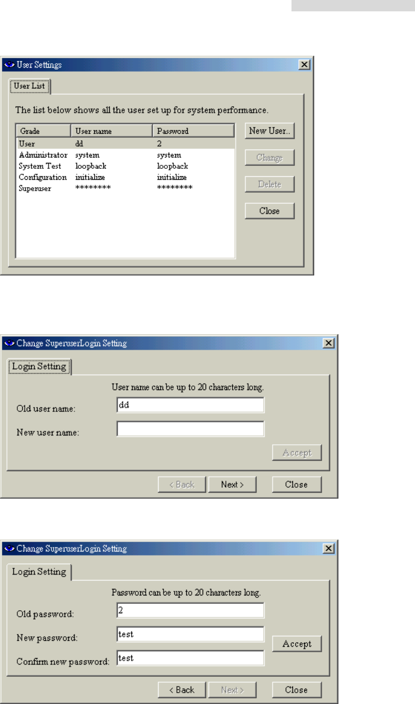
52
Edit User Name or Password: Click on the User Name “dd”. Press the Change button. The
following dialog box appears. You may now change the old user name to a new one. Press
Next to continue.
A new dialog box appears to confirm a new password. Press Accept button to write the
data.
5.8GHz PDH User’s Manual
53
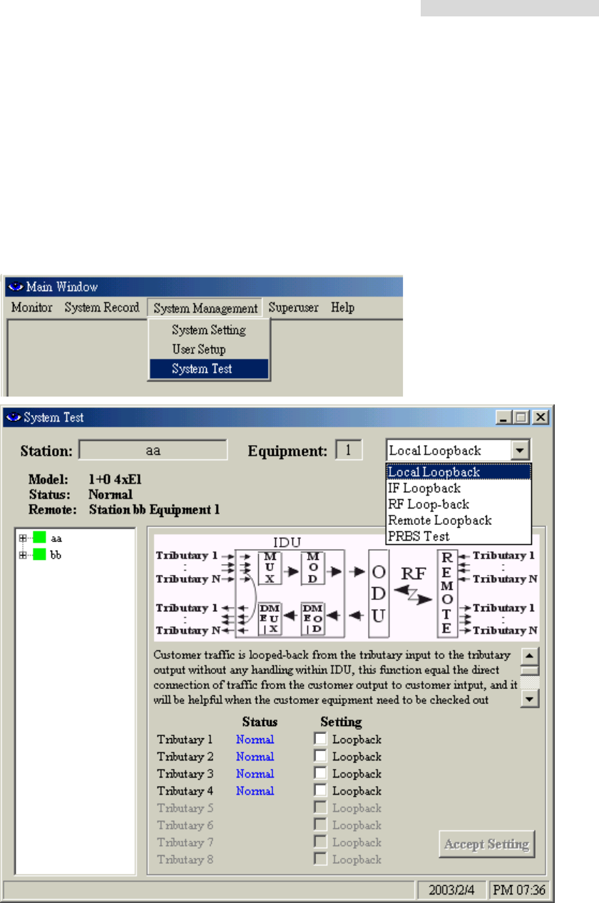
8.7 System Test
In the Main Window, select System Management Æ System Test. The System Test window
has the following functions: Local Loopback、IF Loopback、RF Loopback、Remote
Loopback、PRBS Test.
Note: Check all online communication status while performing any of the loopback
functions. Be careful to check if there is any broken link.
5.8GHz PDH User’s Manual
54
8.7.1 Local Loopback
Local Loopback: Under the local loopback mode, it is easier to detect any malfunction at
the E1 interface. Testing equipment is required while detecting because on the execution
of this function, the testing signal cannot enter MOD, so it is not possible to use PRBS to
detect. This function setting is done through the NMS or the LCD display button.
In the System Test window, tick the Setting column for Tributary1. Press Accept Setting.
The IDU’s first E1 interface is now performing the local loopback test. There can be
multiple selection of the test. Press Clear All Test to stop all the settings performing the
test.
Local Loopback
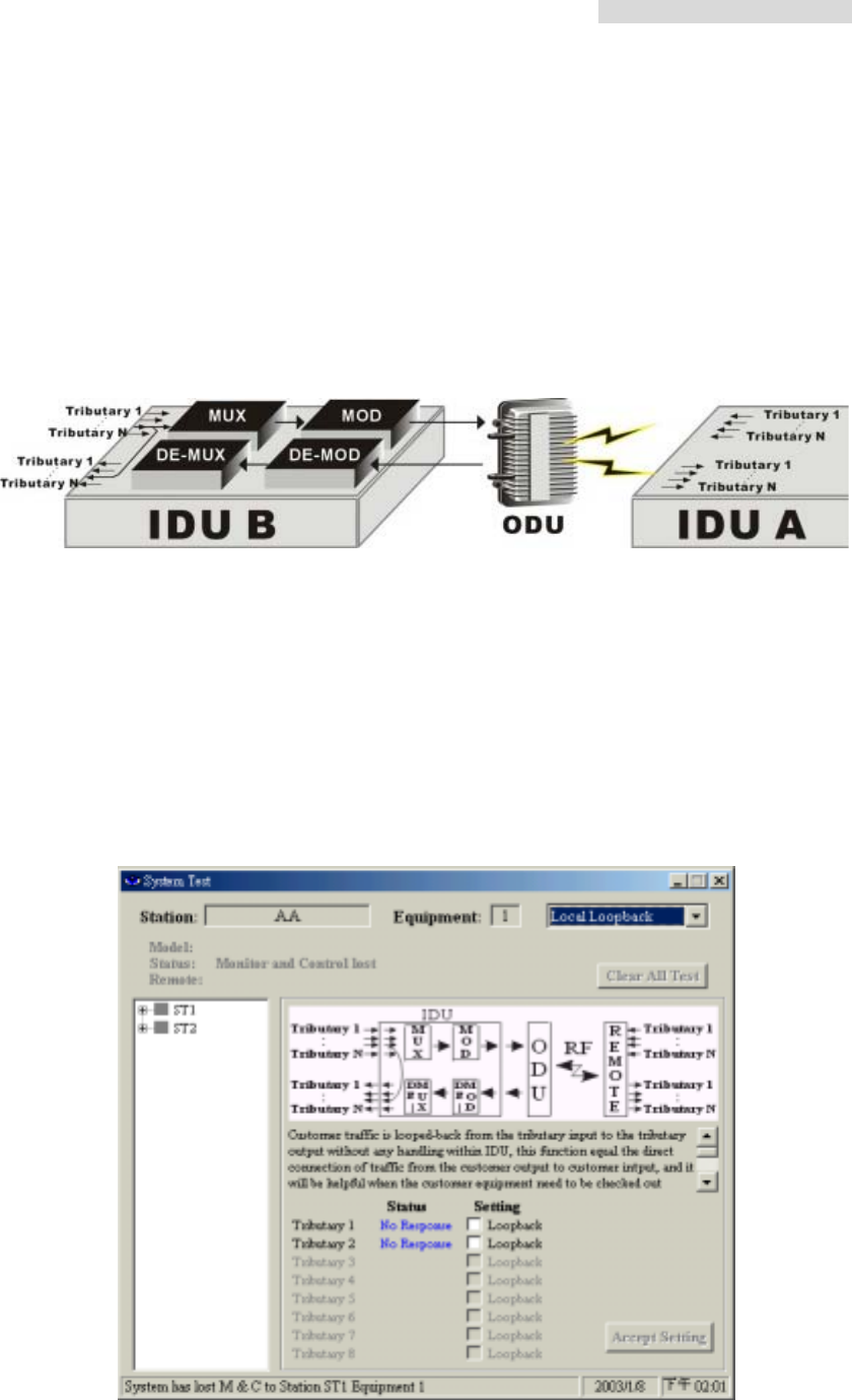
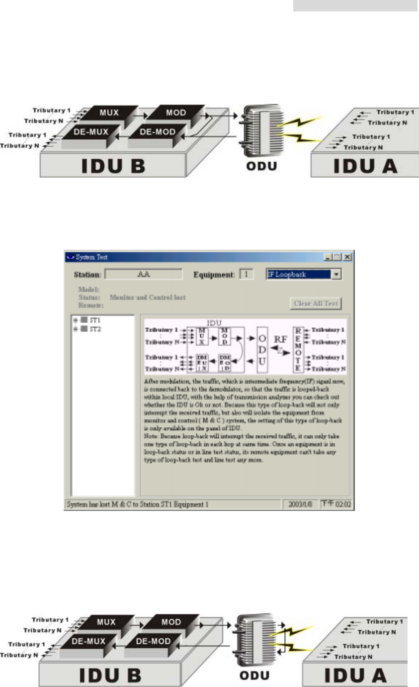
8.7.2 IF Loopback
5.8GHz PDH User’s Manual
55
IF Loopback: Under the IF Loopback mode, a self-detection test on any IDU components
malfunction is carried out. This function setting is done through the LCD display button.
IF Loopback
This function is performed only through the IDU LCD panel.
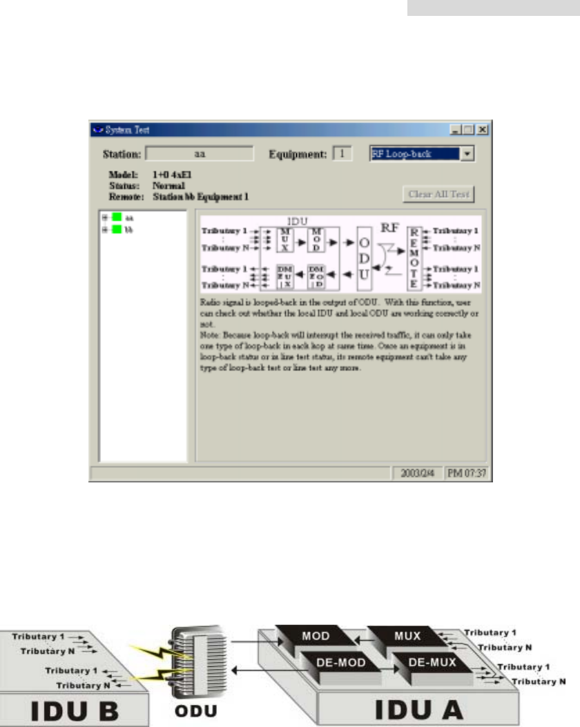
8.7.3 RF Loopback
RF Loopback: Under the RF Loopback mode, a self-detection test on the working
conditions of both the IDU and ODU is carried out. This function setting is done through the
LCD display button.
RF Loopback
5.8GHz PDH User’s Manual
56
This function is performed only through the IDU LCD panel.
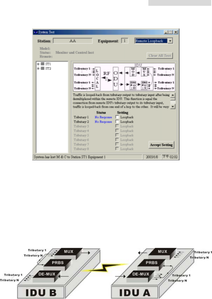
8.7.4 Remote Loopback
Remote Loopback: Under the Remote Loopback mode, a self-detection test on the whole
loopback from local to remote is carried out. This function setting is done through the NMS
or the LCD display button.
Remote Loopback
5.8GHz PDH User’s Manual
57
While performing remote loopback function test, first select the testing tributary. Press Accept
Setting to execute this function. Press Close All Test to end the test.
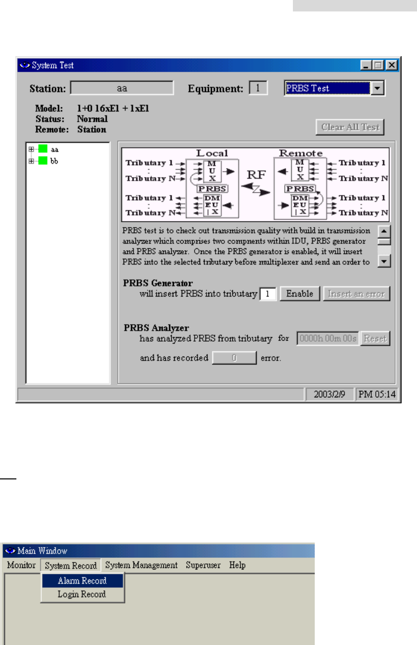
8.7.5 PRBS Test
PRBS Test: Under normal working condition, other than the normal BER test, the PRBS
function can be used as well to test the mono test accumulated BER and PRBS test
stability of the system. While detecting, the PRBS function needs to be started. This
function setting is done through the NMS or the LCD display button.
PRBS Test
5.8GHz PDH User’s Manual
58
8.8 System Record
In the Main Window, select System Record. Another initialization window will appear with
two different working mode: Alarm Record、Login Record.
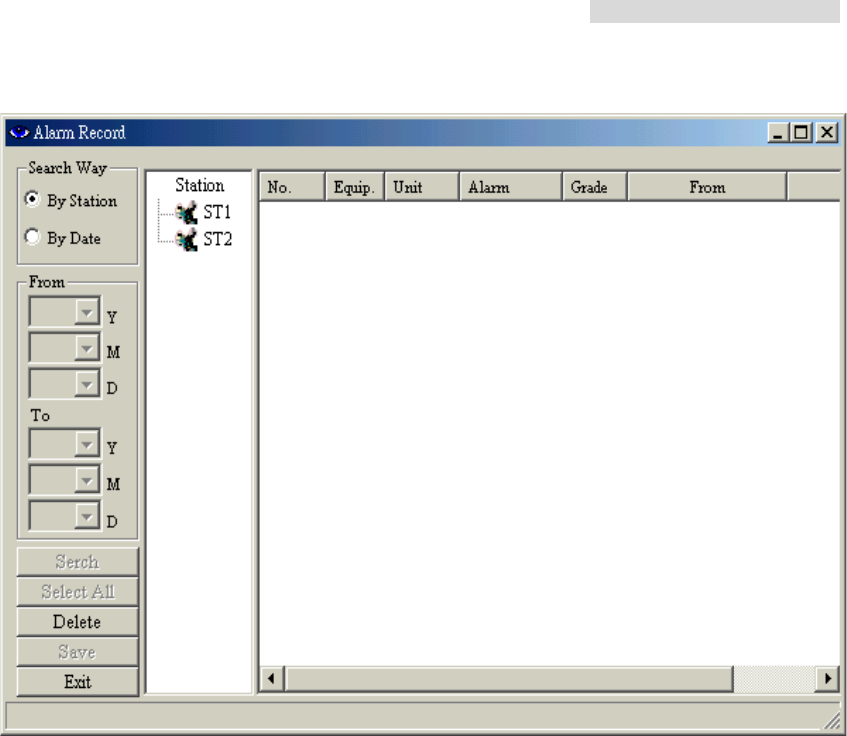
8.8.1 Alarm Record
In the Main Window, select System Record Æ Alarm Record.
The following window appears: All the alarm record in the network will be recorded in here.
5.8GHz PDH User’s Manual
59
5.8GHz PDH User’s Manual
60
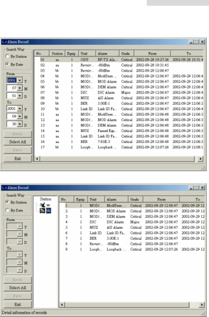
Alarm record sorted by date: In Search Way, tick By Date.
Alarm record sorted by station: In Search Way, tick By Station
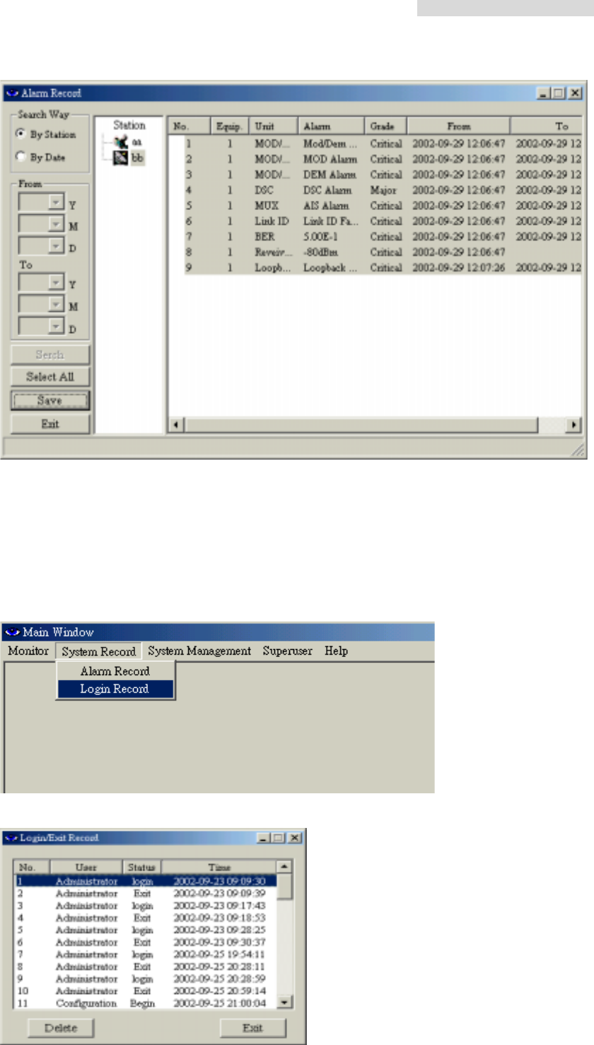
Press the Select All button to select all the alarm record. Press the Save button to save the
files. The following Save As window will appear. Select the desired folder and file name.
Press the Save button.
The file will be saved as *.txt. You may use any word processor to open the file.
5.8GHz PDH User’s Manual
61
Single Deletion: Select the record you need to delete. Press the Delete button.
Overall Deletion: Press the Select All button and press the Delete button.
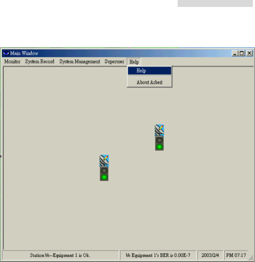
8.8.2 Login Record
In the Main Window, select System Record Æ Login Record. Another initialization window
will appear.
Select the record you need to delete. Press the Delete button.
5.8GHz PDH User’s Manual
62
8.9 Help
5.8GHz PDH User’s Manual
63
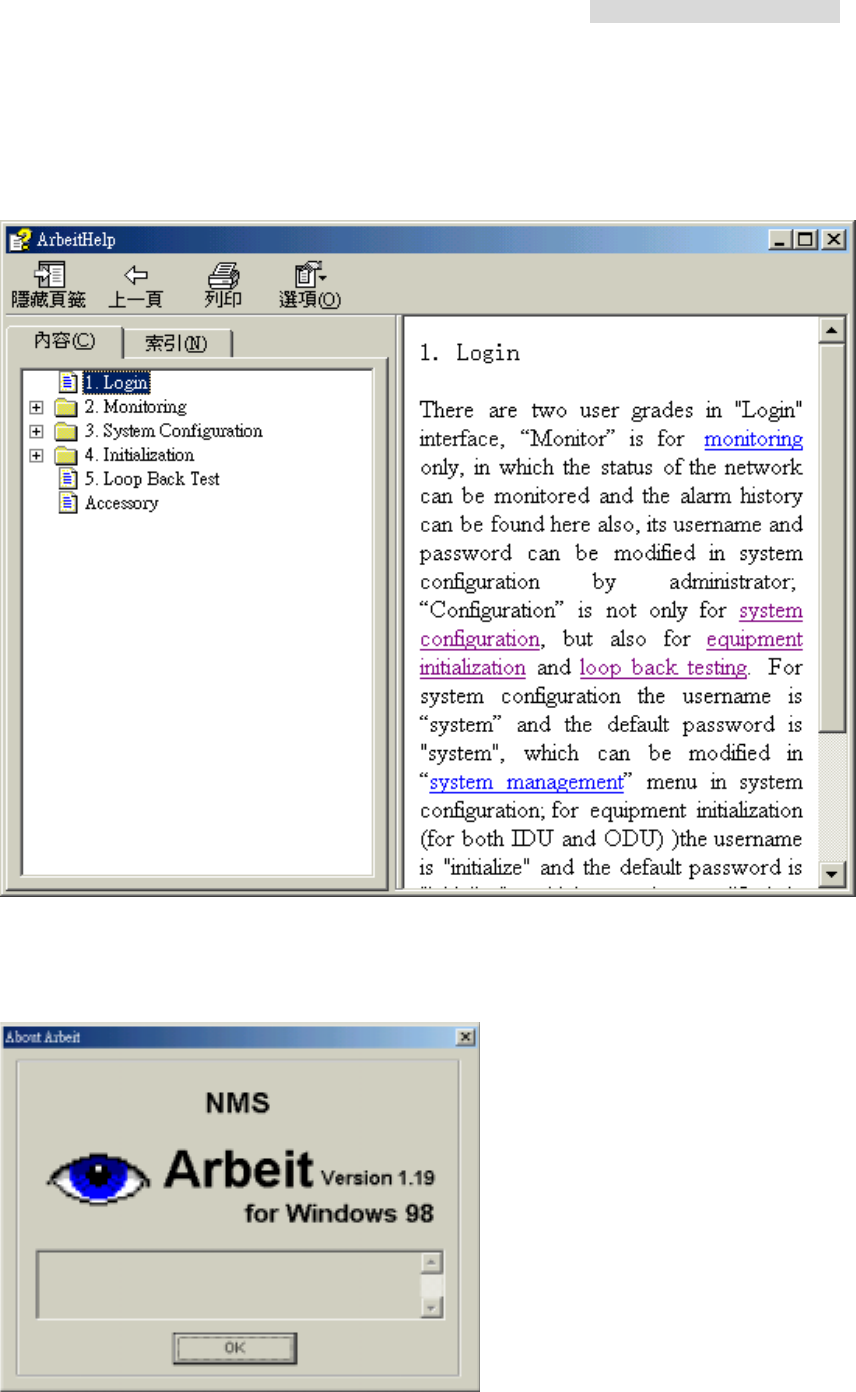
8.9.1 Help Window
You can either select the topics from the Contents or enter keywords to search for specific
information.
8.9.2 About Arbeit
Check Arbeit version.
5.8GHz PDH User’s Manual
64
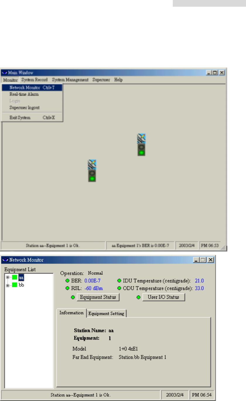
8.10 Monitor
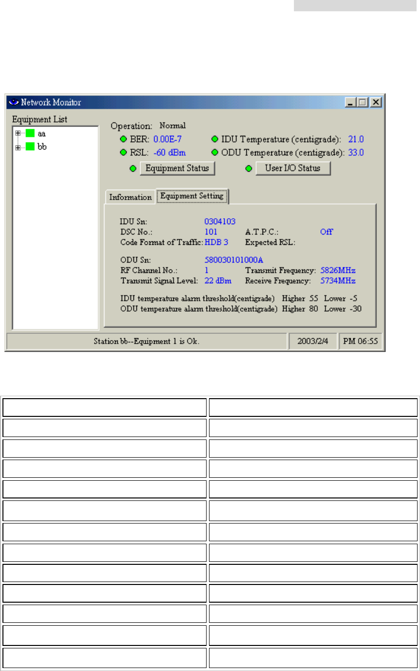
8.10.1 Network Monitor
In the Main Window, select Monitor Æ Network Monitor.
5.8GHz PDH User’s Manual
65
Network Monitor monitors all the station link route information as shown in the following
diagram:
Equipment*2E1
Equipment*2E1
Equipment*2E1
Equipment*4E1Equipment*2E1
Equipment*2E1
Equipment*4E1
Equipment*4E1
Equipment*4E1
Equipment*2E1
Equipment*2E1
Equipment*2E1
16*E1
監控
Desktop PC
Max Equipment 255
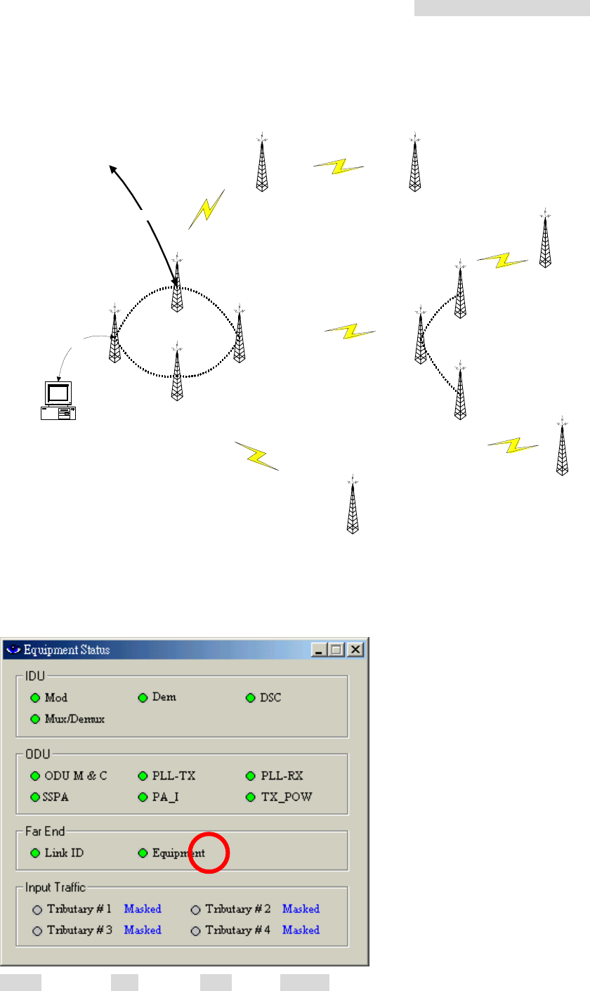
In the above Network Monitor window, click on the Equipment Status button. The following
dialog box appears:
Green = normal; Red = alarm; Grey = lost; Orange = test
5.8GHz PDH User’s Manual
66
Equipment Status
Unit Status Description
Mod Modulation alarm
Dem Demodulation cannot detect the pulse
DSC Abnormal service signal
IDU
Mux / Demux De/modulation alarm
ODU M & C ODU control panel signal loss
PLL-TX RF TX local oscillator lock malfunction
PLL-RX RF RX local oscillator lock malfunction
SSPA Transmitting power alarm
PA_I PA alarm
ODU
TX_POW Transmitting power alarm and relay alarm
if above ±2dB
Link ID Link ID error
Far End
Far End Equipment Far end equipment alarm
Tributary #n AIS IDU detect tributary n with all signal as 1
Tributary #n LOS IDU detected tributary n with no signal
input
Input Traffic
Tributary #n no response IDU cannot detect any tributary status
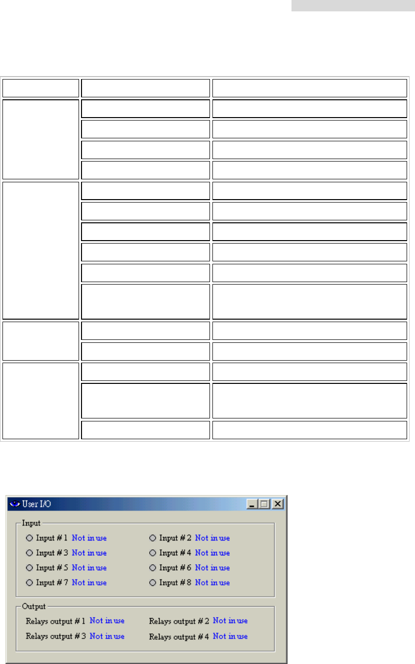
In the above Network Monitor window, click on the User I/O Status button. The following
dialog box appears:
Input = Input port status; Output = Relays output port status
5.8GHz PDH User’s Manual
67
Select the Equipment Setting tab beside the Information tab, it will show the following
information:
Equipment Setting
Status Description
IDU Sn IDU serial number
DSC No Digital service telephone number
Code Format of Traffic E1 encoding type
A.T.P.C. Automatic power control (retain)
Expected RSL Automatic power setup parameter (retain)
ODU Sn ODU serial number
RF Channel No. RF signal channel
Transmit signal Level ODU transmitting power setup
Transmit Frequency ODU transmitting frequency
Receive Frequency ODU receiving frequency
IDU temperature alarm threshold (℃) IDU temperature alarm
ODU temperature alarm threshold (℃) ODU temperature alarm
5.8GHz PDH User’s Manual
68
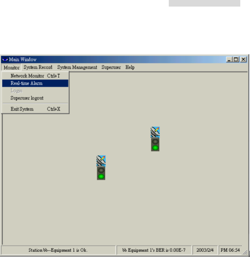
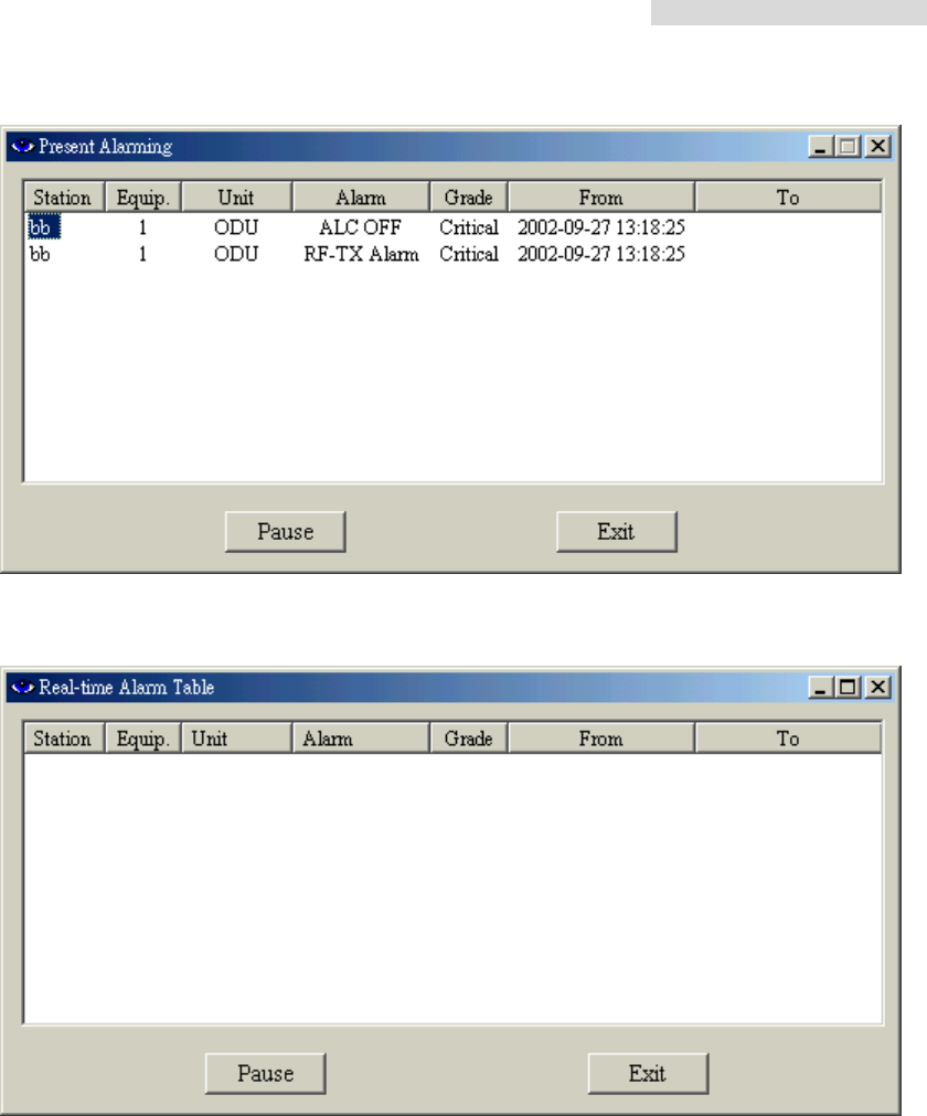
8.10.2 Real-time Alarm
In the Main Window, select Monitor Æ Real-time Alarm.
Until and unless the problem is removed or if the whole system is switched off, the
real-time alarm will still be displayed on the window.
5.8GHz PDH User’s Manual
69
Present Alarming state
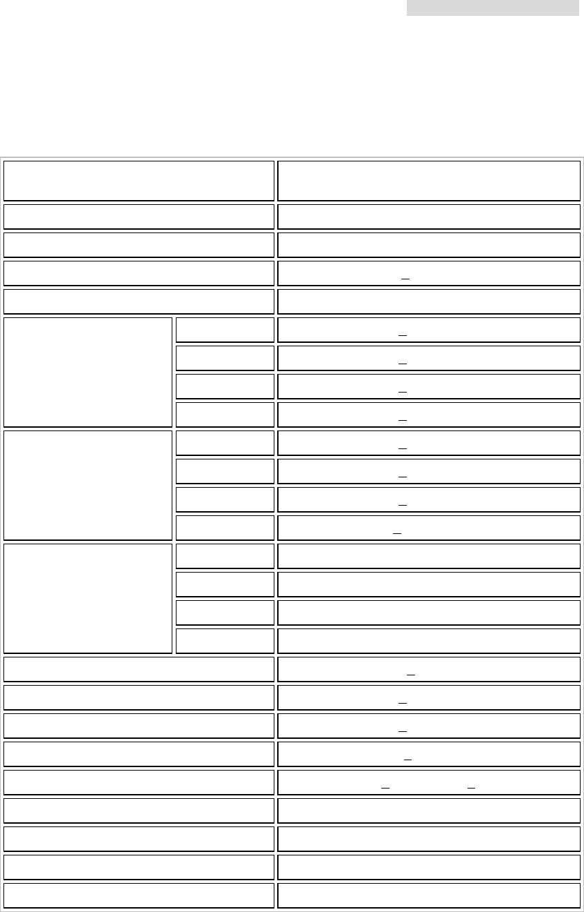
No alarm state
5.8GHz PDH User’s Manual
70
Appendix A: Technical Specifications
Transmitter& Receiver
Operation Frequency 5725~5850MHz
A: 5817~5847MHz ; B: 5727 ~5757MHz
Communication Mode Frequency Division Duplex, FDD
Modulation QPSK
TX Output Power < 22dBm
RX Dynamic Range -84dBm ~ -15dBm
2E1 < -89dBm
4E1 < -86dBm
8E1 < -83dBm
Sensitivity (10-3 BER)
16E1 < -80dBm
2E1 < -87dBm
4E1 < -84dBm
8E1 < -81dBm
Sensitivity (10-6 BER)
16E1 < -77.5dBm
2E1 3 Channel
4E1 3 Channel
8E1 2 Channel
Frequency Selection
16E1 1 Channel
BER During Normal Propagation < 10 -10
Receiver Max Input < -10dBm
Receiver Max Input with no BER < -30dBm
Frequency Stability +10ppm
Gain Flatness (anywhere) RX: + 1 dB TX: + 1dB
TX & RX Isolation 60dB
TVS > 40 kilovolts
PA Control 10~22dBm ( 25) Step 2dB
RSSI (BNC) for Antenna Alignment

5.8GHz PDH User’s Manual
71
Digital Line interface
Data Rate 2,048 Mbps
E1 Connector (ITU-T G.703)
BNC Unbalanced, 75 ohm
OR
Balanced, 120 ohm (Optional)
Signal BER LCD Display on IDU
IDU Structure
IDU LCD Display of IDU, ODU, Remote, Alarm, Test Item
Information
Alarm Buzzer, LED Indication, LCD Display
Green Link OK
Orange Test
LED Indication
Red Alarm
Temperature and Environment
Operating Temperature Range -30 to 65
Humidity 10%~95% Non-condensing
Altitude 5,000 meters (maximum)
Network Management System
Operating Computer PC or Notebook RS232
Operation System Win98、Win Me、Win2000、Win XP
Interface RS232
NMS Name Arbeit
Protocol NMS or SNMP
Control Client 255
NMS Function
IDU Setup、ODU Setup、Remote Loopback、
Local Loopback、PRBS Test、IF Loopback、RF
Loopback、BER、Temperature、Alarm、Recorded
Alarm、Present Alarm、Router Map、Channel
Setup、RSL、Tx Level、Login Record、Display
Alarm etc.
5.8GHz PDH User’s Manual
72
IF Cable
Link Cable < 100m RG-5
< 200m RG-8
Frequency 310MHz ± 50 ppm
Range ±15MHz
Power -30dBm~0dBm
IDU OUTPUT
Return Loss VSWR 1.3
Frequency 70MHz ± 50ppm
Range ±15MHz
Power -20dBm~0dBm
IDU INPUT
Return Loss VSWR1.3
Frequency 11.0592MHz ± 50ppm
Range ±0.5MHz
Power 150~180mVpp
Monitoring Signal
Return Loss Input /Output VSWR 1.3

5.8GHz PDH User’s Manual
73
Service Channel
Frequency 300-3400Hz
Impedance 600 ohm balance
Telephone
Interface RJ-11
Bit Rate 9600 baud
Protocol RS-232
Monitoring Data
(PC)
Interface RJ-45
Bit Rate 9600 baud
Protocol RS-232
Computer Data
(USER)
Interface DB-25
Type Photo-coupled (TTL)
Interface DB-25
Number 8
Isolation 3000 VAC (rms)
User Input
LED Power Dissipation 90 mW
Type Relay output
Interface DB-25
Number 4
Max. switching voltage 125 VAC / 60 VDC
User Output
Max. switching current 1 A
Power
DC Input DC -48VDC (-36~ -72V)
Power Consumption < 45 watts
AC Input (optional) 220 VAC (100-250V) 50-60Hz
Connector Barrier strip, plug-in type

5.8GHz PDH User’s Manual
74
Appendix B: LCD Alarm Description
Alarm Status Reason
MOD Alarm
Cannot send any correct
signal Asynchronous modulation
DEMOD Alarm
Cannot receive any
correct signal Asynchronous demodulation
DSC Alarm
No digital service between
the equipments MUX Unit detecting clock is incorrect
LINK ID Alarm
LINK ID at the remote end
is different from the user’s
setting
RAOUT Alarm
Cannot receive, but can
send signal
Remote terminal will notify the local
terminal of the alarm
MUX Alarm Receiving lock malfunction Tapping procedure cannot lock the
timing
I n-LOS Loss IDU cannot detect the
input tributary signal
I1 - AIS Alarm Tributary signal input are
all 1’s
ODU – M/C Alarm IDU cannot monitor ODU M&C channel between IDU and ODU
is down
5.8GHz PDH User’s Manual
75
Alarm Info, IDU Info, ODU Info, TEST Item and Remote Info have the same function
precedence. Each function can be mutually switched back and forth using the Right/Left
button. For example, if it is now processing the Alarm Info function table. When the Right
button is pressed, you’ll be directed to the IDU Info menu. Now press the OK button to
enter the Menu sub-function table, e.g. Local ID etc.
Press OK to enter the
sub-function display

5.8GHz PDH User’s Manual
76
Appendix C: LCD Display&Function Table
Status LCD Display Function Description
1 Local ID: n Display the local address Display the local equipment’s
address
2 DSC No.: n Display the service number Display the local equipment’s service
telephone number
3 IDU: n x E1 Display the activity measure Display the number of E1 equipments
4 Code: AMI/HDB3 Display or set-up the model
number
Display or set-up the E1 equipments
model number
5 ATPC: En/Dis Automatic Transmit Power
Control Retain
6 EXP_RSL: - n dBm Automatic Transmit Power
Control parameters Retain
7 I-Temp: n IDU working temperature
IDU
Info
(A)
8 Buzzer: ON/OFF Buzzer switch
1 RF CH/Freq. Display RF channel and
frequency limit
Display the present ODU RF channel
and frequency range
2 TxL_Set: n dBm Display the transmit power Display the transmit power, n =
5~22dBm
3 Tx-Mute: ON/OFF To set the PA to ON/OFF
ODU
Info
(B)
4 O-Temp: n ODU working temperature
1 Tn_Loc -Loop: En/Dis Set-up local loopback function
Perform loopback test in the local end
for the convenience of testing the
local end equipment’s stability
2 Tn_ Rem -Loop: En/Dis Set-up remote end loopback
function
Perform loopback test in the remote
end for the convenience of testing the
local end equipment’s stability
3 Tn_PRBS12: En/Dis Bit error transmission test Use Pseudo Random Code to test
the E1 signal transmission
4 Error_ADD: ? Manual addition of bit error Bit error is produced each time the bit
error transmission test is started
5 Ber_Clear: ? Clear all accumulated bit error Clear all accumulated bit error on
starting the bit error transmission test
6 Acc_Ber: num E -n Accumulated bit error display
status
Display all the up-to-date
accumulated bit error on starting the
bit error transmission test
7 IF-Loop: En/Dis Set-up IF loopback function
Perform loopback test from IF
interface for the convenience of
testing the IDU’s stability
TEST
Item
(C)
8 Close-Test: Y/N Close all test Y: close N: cancel
1 Local ID: n Display the remote end
address
Display the address of the remote
equipment; n=1~255
Remote
Info
2 Far-end: Alarm/OK/Loss Display the connection status
of remote end equipments
Alarm: remote monitor function fails
OK: in connection
Loss: R_MON signal loss

5.8GHz PDH User’s Manual
77
(D)
3 R-Status:
Test/Normal/Loss
Display the system present
working status
Test: remote end in testing status
Normal: normal working condition
Loss: R-Status signal loss
5.8GHz PDH User’s Manual
78
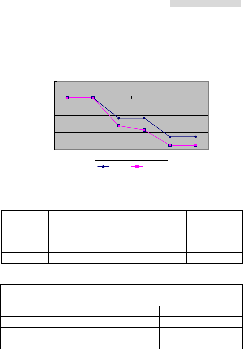
Appendix D: Frequency Spread Spectrum
-60
-40
-20
0
20
+1 f1 f2 f3 f4 f5
QPSK 16QA
M
Example of the transmitting spectrum
Bit Rate
(Mbit/S)
Channel
Spacing
(MHz)
F1
(MHz)
F2
(MHz)
F3
(MHz)
F4
(MHz)
F5
(MHz)
1 4*E1 7 2.7 5.6 6.5 13 17.5
2 4*E1 7 2.8 5.6 7 14 17.5
TX RX
7MHz 4E1
channel Left Middle Right Left Middle Right
1 5730.5 5734 5737.5 5822.5 5826 5829.5
2 5738.5 5742 5745.5 5830.5 5834 5837.5
3 5746.5 5750 5753.5 5838.5 5842 5845.5
(Frequency Unit: MHz / QPSK)
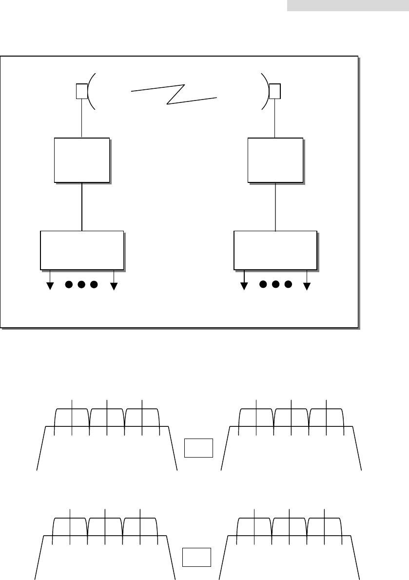
5.8GHz PDH User’s Manual
79
ODU
A
IDU
Mode
ODU
B
IDU
Mode
E1 E1
IF Cable IF Cable
5847 5727 5757
5734 5742 5750
5817
5826 5834 5842
RX BW=7MHz TX BW=7MHz
4E1
5847 5727 5757
5734 5742 5750
5817
5826 5834 5842
TX BW=7MHz RX BW=7MHz
4E1
A
B
5.8GHz PDH User’s Manual
80
Appendix E: 5.8GHz ODU Block Diagram
IF 310MHz
TX 5.85GHz+15MHz
-48V 0.5A 11.0592MHz
RX 5.745GHz+15MHz
IF 70M
ODU A receiving unit
IF 310MHz + 15MHz
TX 5.745GHz+15MHz
RX 5.85GHz+15MHz
IF 70M + 15MHz
ODU B receiving unit
5.8GHz Point-to-Point Monitoring System
E1 Modem
11.0592MHz + 0.1MHz
ASK
5.8GHz PDH User’s Manual
81
Appendix F: ODU Installation Guide
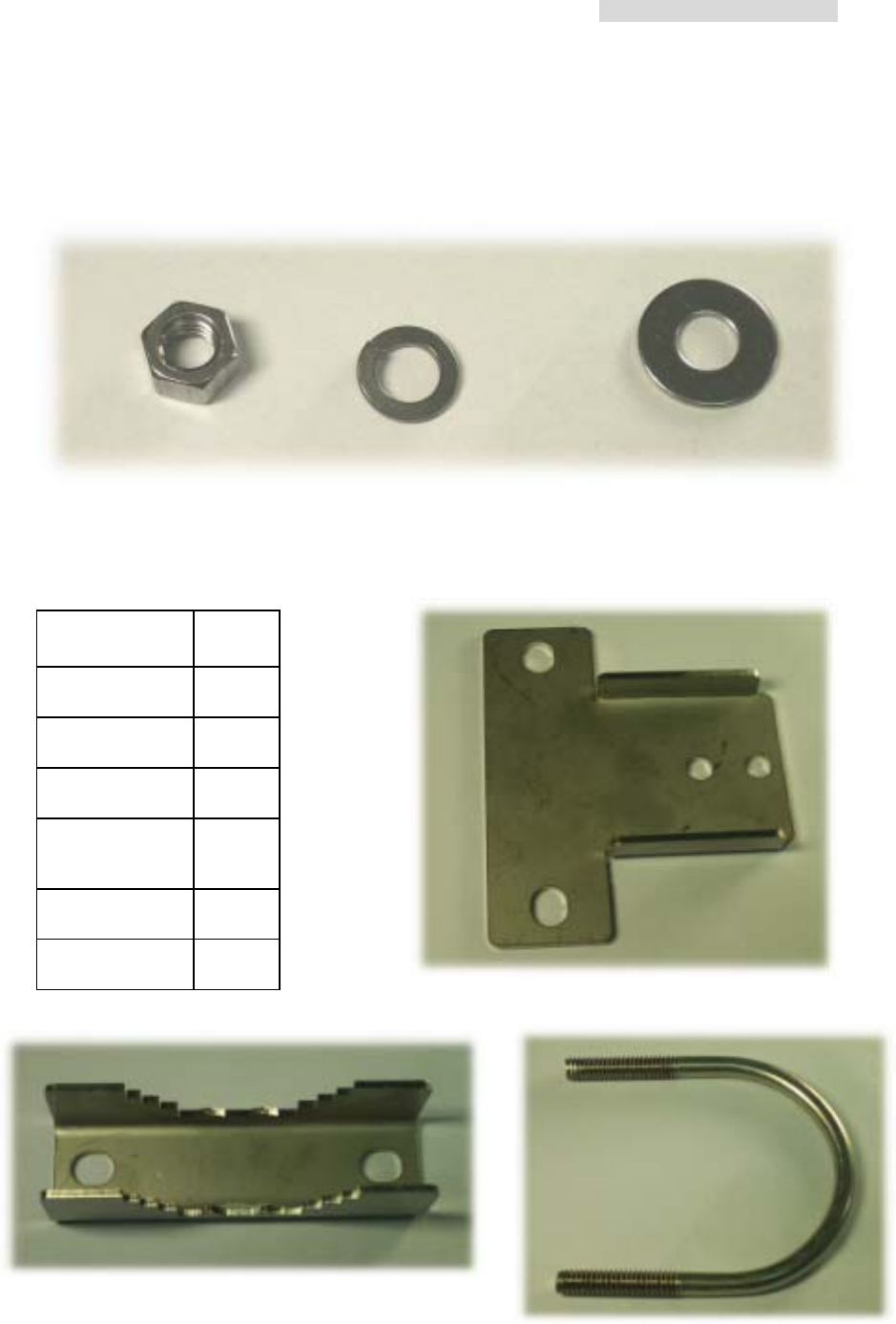
Parts of ODU assembly
Nut[1] Washer[2] Washer[3]
ODU Fastening Assembly
Retaining Ring[4]
Vee Block[5] U-Bracket[6]
Name Quantity
Screw[1] 4
Washer[2] 4
Washer [3] 4
Retaining
Ring[4] 2
Vee Block[5] 2
U-Bracket[6] 2
5.8GHz PDH User’s Manual
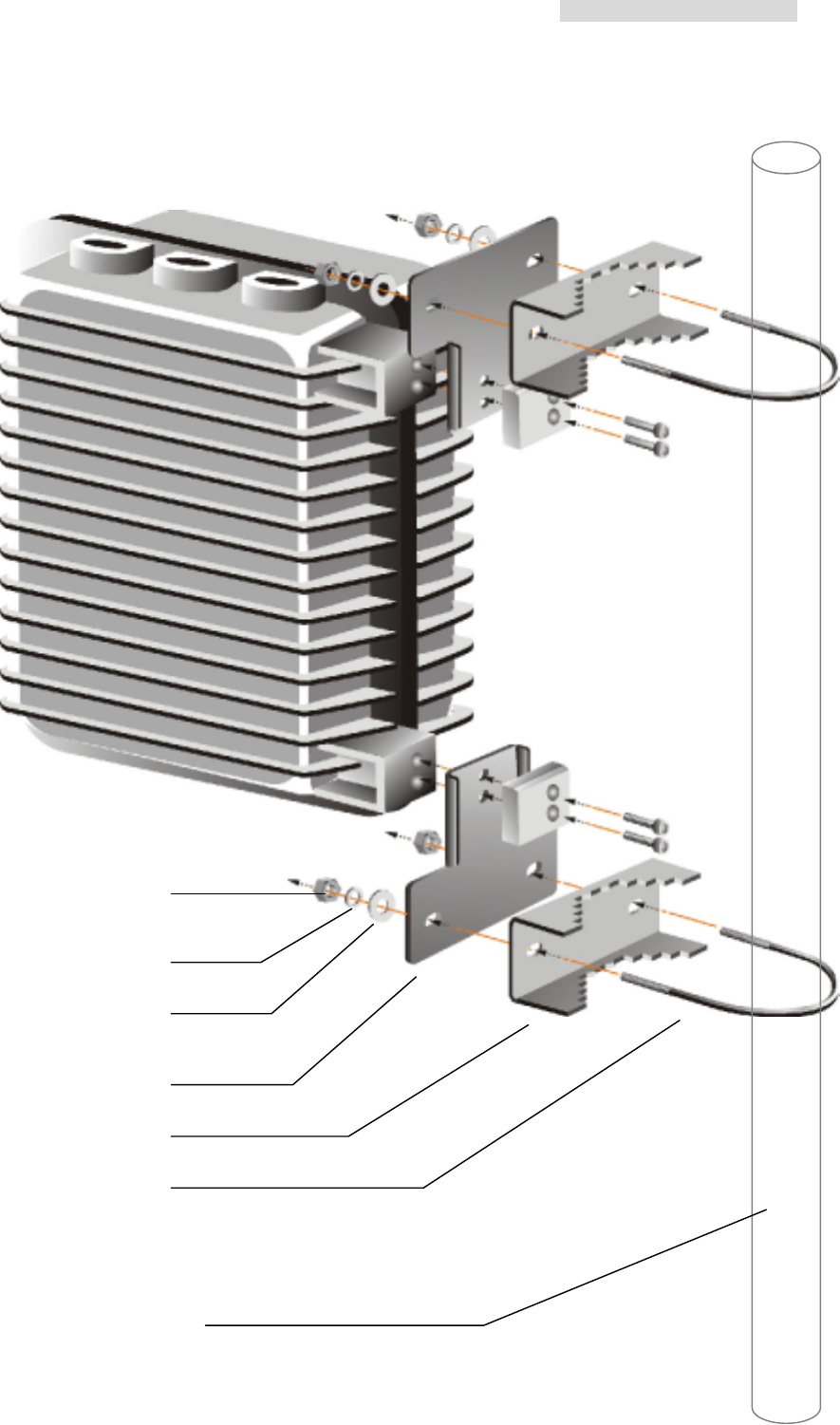
82
ODU Quick Installation Diagram
1
2
3
4
5
6
ODU Mast
5.8GHz PDH User’s Manual
83
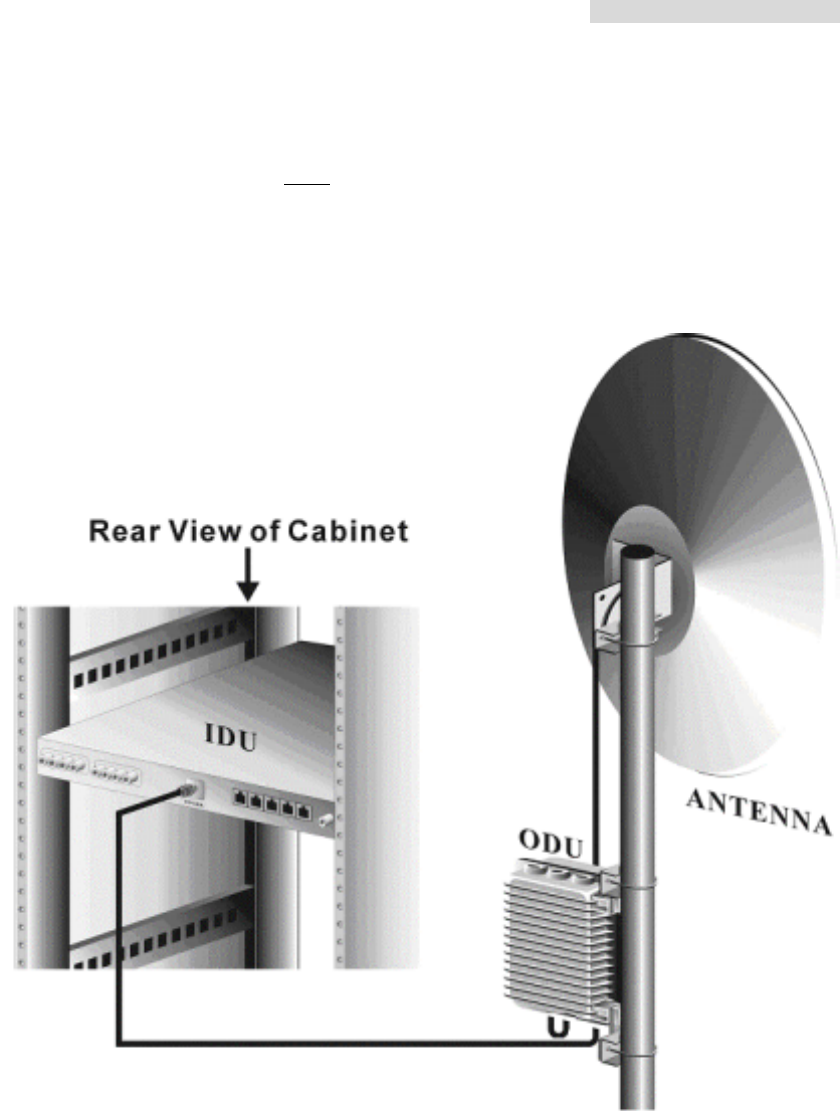
IDU + ODU Quick Installation Guide
※Note: Experts guidance is a must for the installation of this particular equipments
5.8GHz PDH User’s Manual
84
Appendix G: RSL Calculation and Link Budget
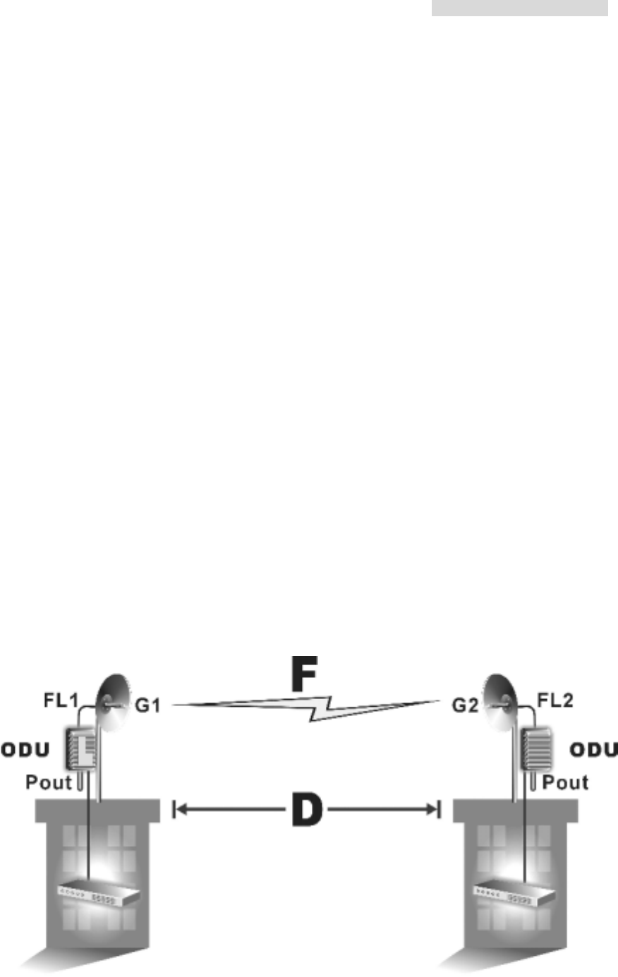
The received signal level (RSL) can be estimated using the following formula:
RSL (dBm) = Pout – FL1 + G1 + G2 – FL2 – LP
where: Pout is the transmitter output power (in dBm)
FL1 is the feeder loss of the transmit side (in dBm)
G1 is the gain of the transmit antenna (in dB)
G2 is the gain of the receive antenna (in dB)
FL2 is the feeder loss of the receive side (in dB)
LP is the Path loss, defined by:
LP (dB) = 96.6 + 20 log10F + 20 log10D
where: F = Frequency in GHz (1.5, 2.4 or 5.8)
D = Distance of path in miles
This link budget is very important for determining any potential problems during installation.
If you have calculated the expected RSL, you can see if it has been achieved during
installation, and troubleshoot if necessary.
5.8GHz PDH User’s Manual
85
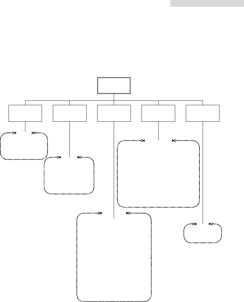
Appendix H: Arbeit Network Management System Tree
Arbeit NMS
System
Management SuperuserSystem Record HelpMonitor
1.Network Monitor
2.Real-time Alarm Table
3.Login/Logout
4.Exit System
1.Alarm Record
a.Check by Station/date
b.Save as Excel/txt
c.Delete
2.Login Record
a.Delete Record
1.System Setting
a.Main Window Background Setting
b.COM port Setting
c.Record Saving Time Setting
2.User Setup
a.New User
b.Delete User
c.User Setting Change
3.System Test
a.Local Loopback
b.Remote Loopback
c.PRBS Test
(1)PRBS send
(2)Insert an Error
(3)Clear Error Counter
(4)Show Error in Rate/Number
d.IF Loopback
e.RF Loopback
1.Network Setting
a.Station Name
b.Station Type
c.Station Temperature Alarm Threshold
d.Add/Delete Equipment in a Station
e.Equipment Configuration
2.Equipment Setting
a.IDU Setting
b.ODU Setting
c.Alarm Setting
d.Output Cross Connect
e.User I/O Setting
C
A
B
D
1.Help
2.About Arbeit
E

5.8GHz PDH User’s Manual
86
Appendix I: Arbeit NMS Alarm
Alarm Grade Status Unit Reason
MOD/DEM Unit Fault Critical No signal in both directions MOD/DEM Hardware troubleshoot
MOD Alarm Critical Can't send any correct signal MOD/DEM
DEM Alarm Critical Can't receive any correct signal MOD/DEM
DSC Unit Fault Major No digital service between the
equipments DSC Hardware troubleshoot, but
main network still exist
DSC Alarm Major
No digital service between the
equipments DSC MUX Unit detecting clock is
incorrect
LINK ID Fault Critical LINK ID at the remote end is
different from the user’s setting LINK ID
Loopback Test Critical IDU is in Loopback Testing state Loopback
Far-end Equipment Alarm Critical
Far-end equipment can't receive
correct signal, but can send correct
signal
MUX
Far-end equipment notifies
the other end of the
alarming condition
MUX Fault Critical No signal in both directions MUX Hardware troubleshoot
AIS Alarm Critical
Equipment can't receive any correct
signal MUX
If DEM alarms, MUX Unit
will send an AIS to indicate
that the MUX Unit is OK
Loss of Frame Loss Critical Equipment can't receive any correct
signal MUX
If BER is too high, MUX Unit
can't detect any correct
signal
Group Loss Critical
Equipment can't receive any correct
signal MUX MUX Unit can't detect the
MOD/DEM Unit’s clock.
TRIB X Loss Critical IDU can't detect any signal from this
tributary MUX
CABLE Fault Critical IDU loses M&C to the ODU Cable M&C channel between IDU
and ODU is down
TX FIX Lock Fault Critical TX lock malfunction ODU Transmitting lock
malfunction
RX FIX Lock Fault Critical RX receives ODU Receiving lock malfunction
Agile Lo. Fault Critical ODU
AGC Off Critical ODU
ALC Off Critical ODU
RF-TX Alarm Critical TX transmitting power ODU
RF-RX Alarm Critical RX receiving power ODU
SSPA Off Critical Transmitting power status ODU
ODU M&C Alarm Critical
No link between IDU and ODU ODU/IDU Cable not connected
PLL-TX Alarm Critical
ODU
PLL-RX Alarm Critical
ODU
PA-A Alarm Critical
ODU
SSPA Alarm Critical
PA switched OFF ODU
TX-POW Alarm Critical
Link ID Alarm Critical
ODU/IDU
Eqijpment Alarm Critical
ODU/IDU
Tributary #n loss Alarm Critical
IDU
Tributary #n AIS Alarm Critical
IDU
IDU Temperature Alarm Major Below IDU temperature threshold IDU
BER Alarm Critical Bit Error Rate

5.8GHz PDH User’s Manual
87
ODU Temperature Major Below receiving power range
RSL Critical Below ODU temperature threshold

5.8GHz PDH User’s Manual
88
Appendix J: ODU Troubleshooting Guide
If the equipment is NOT functioning properly after installation, please check the
following conditions:
I. Local end Equipment not found in Arbeit.
A. IDU - Is the red or green indicator light ON?
1. Check if the DC connector is loose.
2. If NOT, use a voltmeter to check if the DC output is -48V.
3. If there is no problem as define above, please contact us.
B. ODU interface connection.
The ODU has two N-type connectors: Antenna IF Port and IF Port.
Check if all the connections are properly connected.
C. ODU power indicator.
When the ODU is properly connected to the IDU, the IDU’s IF cable transmit three IF
signal and DC -48V. If the light is not glowing, use a voltmeter to check if the coaxial
cable connection is working normally.
Red light indicates NO CONNECTION to PDH.
Green light indicates CONNECTION to PDH.
II. Other equipments not found in Arbeit.
1. Check if the other equipments’ Channel that need to be linked have the same setting.
2. Check if any critical alarm has occurred.
3. The frequency band may be occupied by other user. Try to change for free Channel.
4. Check if Arbeit’s IDU ID conflict with the other equipments’ similar setting.
5. Check if Arbeit’s IDU Link ID is same as that of the other equipments that need
linking.
III. Unable to simultaneously monitor multiple set of equipments from the
same PC.
Check if the NMS1 & NMS2 transmission line’s connection mode is correct.
IV. Cannot execute Loopback test.
1. Check if the IDU LED is OK. Green glow indicates normal.

5.8GHz PDH User’s Manual
89
2. Far-end equipment performing local, IF or RF loopback simultaneously.

5.8GHz PDH User’s Manual
90
Appendix K: Antenna
5.8GHz Directional Antenna
Dimensions-mm 200 x 200 x 30 mm3
Gain-dBi 19 dBi
Half-Power Beam width H-plane 14
E-plane 13
F/B Ratio 30 dB
VSWR < 1.4
Maximum Input Power-W 50
Mounting hardware-mm 30~70 mm
Tiltable Range Hor. 360 Ver. 0~15
Weight-Kg 0.4 kg
For Point to Point Operation Only