K Best Technology KBW2458-001 KBW58 Converter With NDC WLAN Access Point User Manual Revised Users Manual
K-Best Technology Inc. KBW58 Converter With NDC WLAN Access Point Revised Users Manual
Contents
- 1. Revised Users Manual
- 2. Users Manual of AP
Revised Users Manual
Converter
Installation
Guide
Version 1.2
Copyright
Copyright © 2003 all rights reserved. No part of this publication may be
reproduced, adapted, stored in a retrieval system, translated into any
language, or transmitted in any form or by any means without the
written permission of the supplier.
About This Manual
The purpose of this manual is for the setup of Converter & DC Injector.
This manual, revised as version 1.2 in 2003, includes procedures
assisting you in avoiding unforeseen problems.
Technical Support
If you have difficulty resolving the problem while installing or using the
Converter & DC Injector, please contact the supplier for support.
FCC Notice
Reminder:
To comply with FCC part 15 rules, the Converter must only be
used as a system as FCC certified. The system must also be
professionally installed to ensure compliance with the Part 15
certification. It is the responsibility of the operator and
professional installer to ensure that only certified systems are
deployed in where FCC rules apply. Further, according to FCC
Part 15 regulations, Section 15.247(b)(3)(iii), the installer
must ensure that the high-gain directional antenna used in
this system is used exclusively for fixed, point-to-point
operations and that multiple co-located intentional radiators
transmitting the same information are not used. For further
information, please see Appendix B.
FCC Certified Declaration:
This device complies with part 15 of the FCC rules. Operation
is subject to the following two conditions: (1) This device may
not cause harmful interference and (2) this device must accept
any interference received, including interference that may
cause undesired operation.
Notice:
To comply with the FCC RF exposure compliance requirements, the
antenna(s) used for this transmitter must be installed to provide a separation
distance of at least 2 meters from all persons and must not be co-located or
operating in conjunction with any other antenna or transmitter. No change to
the antenna or the device is permitted. Any change to the antenna or the
device could result in the device exceeding the RF exposure requirements
and void user's authority to operate the device.
Table of Contents
Chapter 1 Introduction ..........................................................5
1-1 Product Kit............................................................................................. 5
1-2 Features and Benefits ....................................................................... 6
1.3 Specifications ....................................................................................... 7
1-4 Calculate Transmit Power................................................................. 9
1-5 Installing the Converter .................................................................. 11
Appendix A: Channels and Cable Attenuations ............................. 12
Appendix B: FCC Certified Systems ................................................... 13
Appendix C: Troubleshooting................................................................ 15

Chapter 1 Introduction
K-Best’s Converter operating on the 5.8GHz ISM band is a high
performance two-way converter and amplifier using Time Division Duplex
(TDD) technology. It is used outdoors to extend the range of wireless
radio communication system such as wireless LAN point-to-point
connection.
K-Best’s DC injector KBDC24E provides DC power to the outdoor
Converter or transponder through the RF feed cable without an additional
power cord. It has some different types of connector for custom
configuration. The standard products are KBDC24E-2N with female N type
at both side, and KBDC24E-AN with female N type at one side and female
SMA at another side.
1-1 Product Kit
Before installation, make sure that you have the following items:
Converter
DC Injector
Jumper Cable
Power Adapter
Installation Guide
NDC Access Point and adapter cable

1-2 Features and Benefits
Convert the operating frequency from 2.4GHz to 5.8GHz band
5725~5850 MHz unlicensed ISM Band
200mW output power level.
20 dB receive gain
Bi-directional TDD technology
Transmitter and receiver LED
Waterproof housing

1.3 Specifications
Specifications for DC Injector
Bias Current / DC Voltage
1.5A (max.) / 15V (max.)
Insertion Loss
1dB
Connector / DC Jack
N type female for both sides / φ 6 mm, center pin φ 2.0 mm
Dimensions / Weight
99.1(H) x 53.5(W) x 21.2(H)mm / 165g
Specifications for Converter
Operating Frequency Range
5725~5850 MHz
Input Frequency Range
2400~2484 MHz
Operating Mode
Bi-directional TDD
LO Frequency & Frequency Stability
3360 MHz; ± 2.0 ppm
Transmitter Output Power
23 dBm (200mW)
Transmitter Gain
Automatically adjusts to 200mW power output
Transmitter Input Power
Min: 3dBm
Max: 13dBm
Receiver Input Power
Max: -25dBm
Receiver Gain
20 dB Typical
Frequency Response Flatness
± 1dB over operating range
Noise Figure
< 5 dB
Switching Time
< 1.5 µs
Connector
N-type Female (50Ω)
Operating Temperature
-30 °C ~60 °C
Power Supply
12 VDC, 1.5A recommended
Power Consumption
700mA @12 VDC
LED Indication
Transmit: Green; Receive: Red
Dimensions
195(L) x 95(W) x 23(H) mm
Weight
720g

1-4 Calculate Transmit Power
In order to obtain the best performance of converter and system, user
must calculate the transmission power to meet the converter technical
requirement and FCC regulations(See Appendix B). It is advised that the
user follows the calculation below:
1. Converter power of the access point from milliwatts to dBm.
Note: dBm = 10 * Log(milliwatts)
2. Determine the attenuation of cable(please refer to manufacturer’s
specifications)
Note: Suggest the cable loss between converter and DC injector should
not exceed 10 dBm generally.
Table B – Typical Cable Attenuation Values
Cable Type Attenuation dB/100ft @2.4GHz
RG-142 21
LMR200 16.5
LMR400 6.6
LMR600 4.4
LMR900 2.92
Belden 9913 7.1
Note: Values are approximate.
10
3. Calculate the actual power of converter in the pole as follow:
Access point Power(dBm) – Cable Loss(dBm) – Misc. Loss = Input
Signal Level(dBm)
Note: Misc. Loss means loss of connector, adapter and DC injector and
estimates to be around 2 dB.
4. If the input signal level exceeds the max. Transmitter Input Power or
fails to meet the min. Transmitter Input Power of converter, the
converter can’t identify the input signal. Under this circumstance, user
should adjust the input signal level to fit the requirement such as using
an attenuation pad or a higher loss cable and vice versa.
11
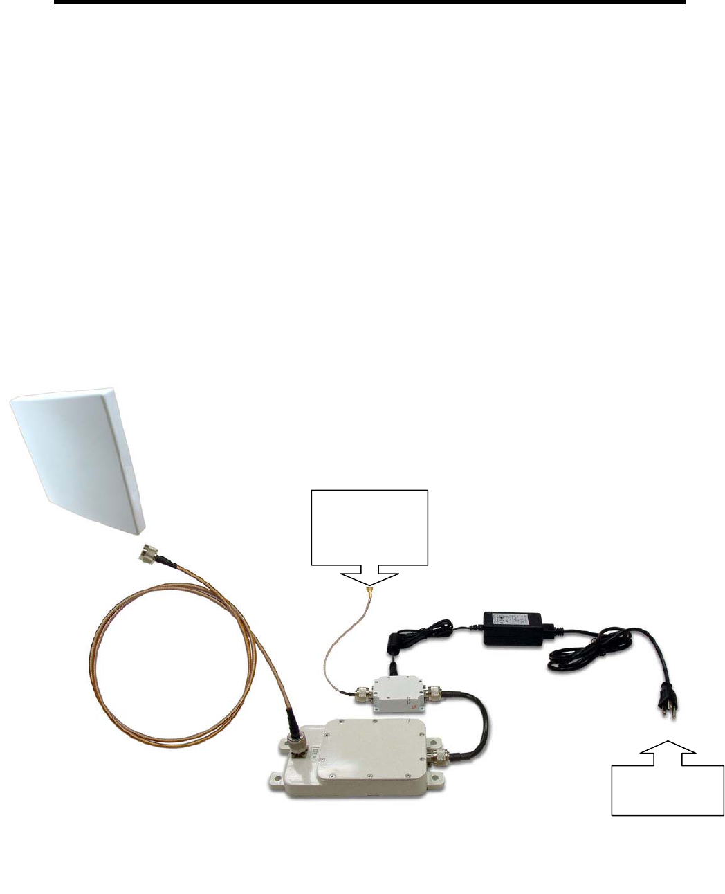
1-5 Installing the Converter
1 Connect the KBW58 RF output directly to the antenna.
2 Attach the KBW58 RF input to the DC Injector with RF cable (Jumper
cable).
3 Connect the RF cable leading from the DC Injector to the antenna on
the Access Point unit.
4 Plug the power cable leading from the DC Injector into any available
110/220 V outlet.
Note: Converter operating on the 5.8GHz ISM band is a high performance
two-way converter and amplifier using Time Division Duplex (TDD)
technology
KBW58 Installation Details
DC Injector
Converter
Jumper Cable
110/220 VAC
Main Power
To 5.8GHz
Antenna
RF Output
interface of
Access Point

12
Appendix A: Channels and Cable Attenuations
Table A – Conversion Table
802.11b
Channel
2.4 GHz
Frequency(MHz)
5.8 GHz
Frequency(MHz)
1 2412 5772
2 2417 5777
3 2422 5782
4 2427 5787
5 2432 5792
6 2437 5797
7 2442 5802
8 2447 5807
9 2452 5812
10 2457 5817
11 2462 5822
13
Appendix B: FCC Certified Systems
FCC ID#: QZGKBW2458-001
FCC Certified Systems consist of:
¾ KBW58-2020 Converter,DC Injector,Power Adapter
¾ NDC WLAN Access Point
¾ Outdoor Antenna
¾ Coaxial Cable
The Converter has passed the FCC regulations:
FCC part 15, subpart C(2002)
Table A – Authorized Antennas
Model Antenna Type Antenna
Gain(dBi)
Max
EIRP(dBm)
KBNT5819-16 Flat Panel 19 42
KBNT5822-16 Flat Panel 22 45
KBNT5826-13 Parabolic Grid 26 49
Note: Cable calculation must be performed using 2.4GHz
attenuation values because all signals pass between the
Access point and Converter are at a frequency of 2.4GHz.

14
Appendix B (Continued)
Table B – Authorized Cables with Minimum Length
Cable Type Minimum Length Maximum
Recommended Length
RG6/U 35 feet 75 feet
RG142 27 feet 60 feet
LMR400 100 feet 250 feet
LMR500 125 feet 300 feet
LMR600 150 feet 370 feet
LMR900 230 feet 560 feet
LMR1200 300 feet 700 feet
LMR1700 410 feet 950 feet
Note: This table is for reference only.
Notice:
This device complies with part 15 of the FCC rules.
Operation is subject to the following two conditions: (1) This
device may not cause harmful interference and (2) this
device must accept any interference received, including
interference that may cause undesired operation.

15
Appendix C: Troubleshooting
If there is no signal output, please check the following item:
1. Check whether the LED indicator on the DC injector is on. If not, it
means there is problem with the power component.
(1) Check if the power cord is correctly connected with the power
adapter and the power outlet.
(2) Check if there is electricity on power outlet.
2. Check if the access point is working properly.
3. Check if the connection between converter and DC injector is correct, or
whether the connector is loose or not.
4. Verify if the transmit power which calculated before is correct.
5. If none of the above measures could solve troubleshooting, please
contact the supplier for further support.