KAPSCH TRAFFICCOM CANADA 801660 Transponder User Manual FPT Interior Transponder Mounting Instructions
KAPSCH TRAFFICCOM CANADA INC. Transponder FPT Interior Transponder Mounting Instructions
Contents
- 1. User manual
- 2. Mounting Instructions
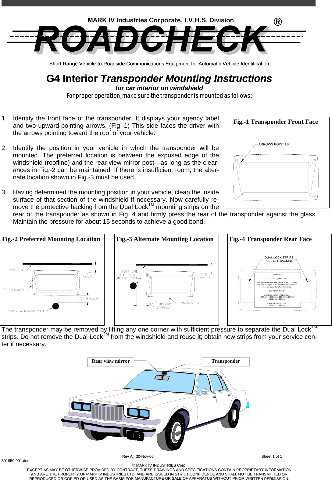
Mounting Instructions