KAPSCH TRAFFICCOM CANADA 801970 G4E Feedback Transponder User Manual FPT Interior Transponder Mounting Instructions

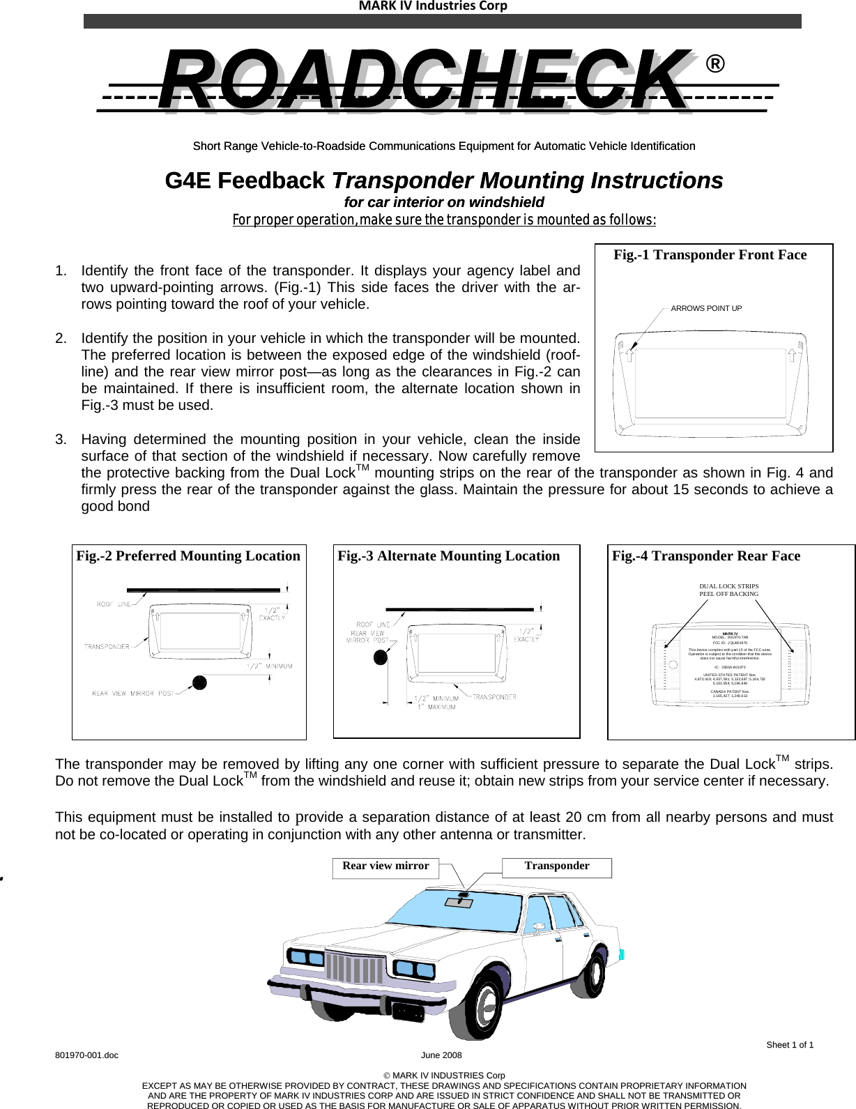
KAPSCH TRAFFICCOM CANADA INC. G4E Feedback Transponder FPT Interior Transponder Mounting Instructions

user manual

MARKIVIndustriesCorp      ®                                                                                                                                                                                                                  SShheeeett  11  ooff  11  880011997700--000011..ddoocc            JJuunnee  22000088    ©©  MMAARRKK  IIVV  IINNDDUUSSTTRRIIEESS  CCoorrpp  EEXXCCEEPPTT  AASS  MMAAYY  BBEE  OOTTHHEERRWWIISSEE  PPRROOVVIIDDEEDD  BBYY  CCOONNTTRRAACCTT,,  TTHHEESSEE  DDRRAAWWIINNGGSS  AANNDD  SSPPEECCIIFFIICCAATTIIOONNSS  CCOONNTTAAIINN  PPRROOPPRRIIEETTAARRYY  IINNFFOORRMMAATTIIOONN  AANNDD  AARREE  TTHHEE  PPRROOPPEERRTTYY  OOFF  MMAARRKK  IIVV  IINNDDUUSSTTRRIIEESS  CCOORRPP  AANNDD  AARREE  IISSSSUUEEDD  IINN  SSTTRRIICCTT  CCOONNFFIIDDEENNCCEE  AANNDD  SSHHAALLLL  NNOOTT  BBEE  TTRRAANNSSMMIITTTTEEDD  OORR  RREEPPRROODDUUCCEEDD  OORR  CCOOPPIIEEDD  OORR  UUSSEEDD  AASS  TTHHEE  BBAASSIISS  FFOORR  MMAANNUUFFAACCTTUURREE  OORR  SSAALLEE  OOFF  AAPPPPAARRAATTUUSS  WWIITTHHOOUUTT  PPRRIIOORR  WWRRIITTTTEENN  PPEERRMMIISSSSIIOONN..    Short Range Vehicle-to-Roadside Communications Equipment for Automatic Vehicle Identification Short Range Vehicle-to-Roadside Communications Equipment for Automatic Vehicle Identification   G4E Feedback Transponder Mounting Instructions G4E Feedback Transponder Mounting Instructions for car interior on windshield for car interior on windshield For proper operation, make sure the transponder is mounted as follows:For proper operation, make sure the transponder is mounted as follows:   1.  Identify the front face of the transponder. It displays your agency label and two upward-pointing arrows. (Fig.-1) This side faces the driver with the ar-rows pointing toward the roof of your vehicle. 2.  Identify the position in your vehicle in which the transponder will be mounted. The preferred location is between the exposed edge of the windshield (roof-line) and the rear view mirror post—as long as the clearances in Fig.-2 can be maintained. If there is insufficient room, the alternate location shown in Fig.-3 must be used. 3.  Having determined the mounting position in your vehicle, clean the inside surface of that section of the windshield if necessary. Now carefully remove the protective backing from the Dual LockTM mounting strips on the rear of the transponder as shown in Fig. 4 and firmly press the rear of the transponder against the glass. Maintain the pressure for about 15 seconds to achieve a good bond  The transponder may be removed by lifting any one corner with sufficient pressure to separate the Dual LockTM strips. Do not remove the Dual LockTM from the windshield and reuse it; obtain new strips from your service center if necessary.  This equipment must be installed to provide a separation distance of at least 20 cm from all nearby persons and must not be co-located or operating in conjunction with any other antenna or transmitter.    Fig.-2 Preferred Mounting Location       Fig.-1 Transponder Front Face               Fig.-4 Transponder Rear Face      MA RK I VMA RK I VFCC ID:  JQU801970This d evice complies with part 15 of the FCC rules.Operation is subject to  the condition that  this devicedoes not cause harmful interference.IC:  2665A-801970UNITED STATES PATENT Nos.4,87 0, 419;  4, 937, 581;  5,13 2,687 ; 5 ,164, 7325,192, 95 4; 5,196 ,846CANADA  PATENT Nos.1,165, 42 7; 1,248 ,613MODEL:  801970-TAB DUAL LOCK STRIPS PEEL OFF BACKING  Fig.-3 Alternate Mounting Location  ARROWS POINT UP Rear view mirror  Transponder

Navigation menu