KAPSCH TRAFFICCOM CANADA 801970 G4E Feedback Transponder User Manual FPT Interior Transponder Mounting Instructions
KAPSCH TRAFFICCOM CANADA INC. G4E Feedback Transponder FPT Interior Transponder Mounting Instructions
user manual
MARKIVIndustriesCorp
®
S
Sh
he
ee
et
t
1
1
o
of
f
1
1
8
80
01
19
97
70
0-
-0
00
01
1.
.d
do
oc
c
J
Ju
un
ne
e
2
20
00
08
8
©
©
M
MA
AR
RK
K
I
IV
V
I
IN
ND
DU
US
ST
TR
RI
IE
ES
S
C
Co
or
rp
p
E
EX
XC
CE
EP
PT
T
A
AS
S
M
MA
AY
Y
B
BE
E
O
OT
TH
HE
ER
RW
WI
IS
SE
E
P
PR
RO
OV
VI
ID
DE
ED
D
B
BY
Y
C
CO
ON
NT
TR
RA
AC
CT
T,
,
T
TH
HE
ES
SE
E
D
DR
RA
AW
WI
IN
NG
GS
S
A
AN
ND
D
S
SP
PE
EC
CI
IF
FI
IC
CA
AT
TI
IO
ON
NS
S
C
CO
ON
NT
TA
AI
IN
N
P
PR
RO
OP
PR
RI
IE
ET
TA
AR
RY
Y
I
IN
NF
FO
OR
RM
MA
AT
TI
IO
ON
N
A
AN
ND
D
A
AR
RE
E
T
TH
HE
E
P
PR
RO
OP
PE
ER
RT
TY
Y
O
OF
F
M
MA
AR
RK
K
I
IV
V
I
IN
ND
DU
US
ST
TR
RI
IE
ES
S
C
CO
OR
RP
P
A
AN
ND
D
A
AR
RE
E
I
IS
SS
SU
UE
ED
D
I
IN
N
S
ST
TR
RI
IC
CT
T
C
CO
ON
NF
FI
ID
DE
EN
NC
CE
E
A
AN
ND
D
S
SH
HA
AL
LL
L
N
NO
OT
T
B
BE
E
T
TR
RA
AN
NS
SM
MI
IT
TT
TE
ED
D
O
OR
R
R
RE
EP
PR
RO
OD
DU
UC
CE
ED
D
O
OR
R
C
CO
OP
PI
IE
ED
D
O
OR
R
U
US
SE
ED
D
A
AS
S
T
TH
HE
E
B
BA
AS
SI
IS
S
F
FO
OR
R
M
MA
AN
NU
UF
FA
AC
CT
TU
UR
RE
E
O
OR
R
S
SA
AL
LE
E
O
OF
F
A
AP
PP
PA
AR
RA
AT
TU
US
S
W
WI
IT
TH
HO
OU
UT
T
P
PR
RI
IO
OR
R
W
WR
RI
IT
TT
TE
EN
N
P
PE
ER
RM
MI
IS
SS
SI
IO
ON
N.
.
Short Range Vehicle-to-Roadside Communications Equipment for Automatic Vehicle Identification Short Range Vehicle-to-Roadside Communications Equipment for Automatic Vehicle Identification
G4E Feedback Transponder Mounting Instructions G4E Feedback Transponder Mounting Instructions
for car interior on windshield for car interior on windshield
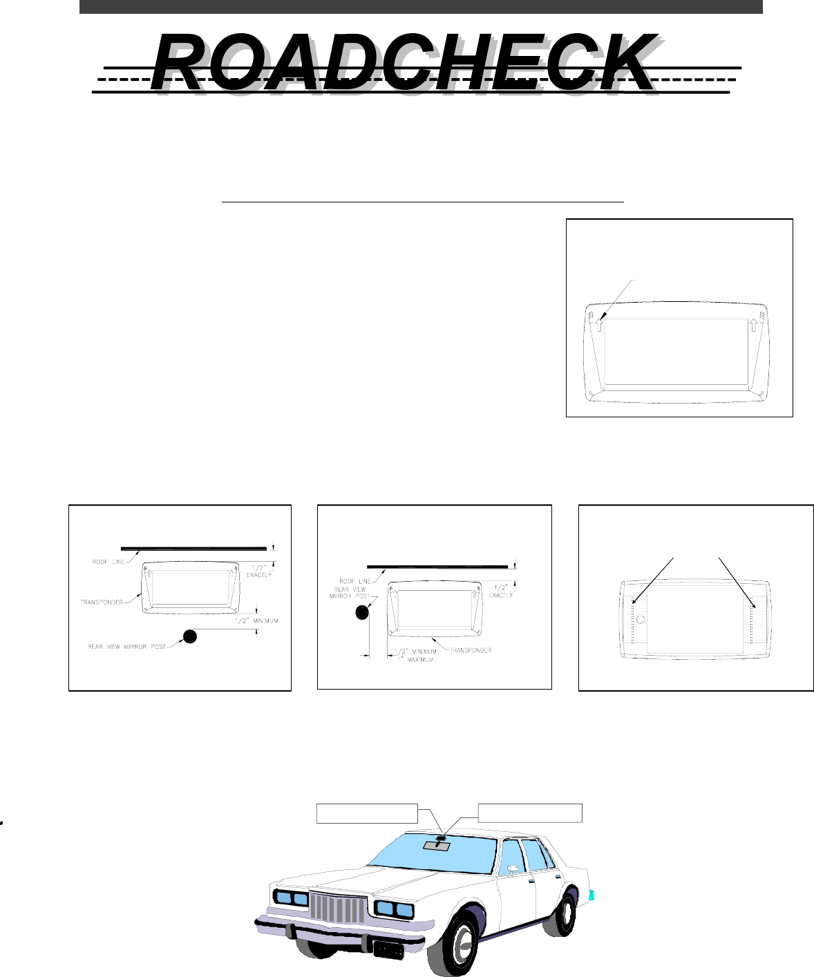
For proper operation, make sure the transponder is mounted as follows:For proper operation, make sure the transponder is mounted as follows:
1. Identify the front face of the transponder. It displays your agency label and
two upward-pointing arrows. (Fig.-1) This side faces the driver with the ar-
rows pointing toward the roof of your vehicle.
2. Identify the position in your vehicle in which the transponder will be mounted.
The preferred location is between the exposed edge of the windshield (roof-
line) and the rear view mirror post—as long as the clearances in Fig.-2 can
be maintained. If there is insufficient room, the alternate location shown in
Fig.-3 must be used.
3. Having determined the mounting position in your vehicle, clean the inside
surface of that section of the windshield if necessary. Now carefully remove
the protective backing from the Dual LockTM mounting strips on the rear of the transponder as shown in Fig. 4 and
firmly press the rear of the transponder against the glass. Maintain the pressure for about 15 seconds to achieve a
good bond
The transponder may be removed by lifting any one corner with sufficient pressure to separate the Dual LockTM strips.
Do not remove the Dual LockTM from the windshield and reuse it; obtain new strips from your service center if necessary.
This equipment must be installed to provide a separation distance of at least 20 cm from all nearby persons and must
not be co-located or operating in conjunction with any other antenna or transmitter.
Fig.-2 Preferred Mounting Location
Fig.-1 Transponder Front Face
Fig.-4 Transponder Rear Face
MA RK I VMA RK I V
FCC ID: JQU801970
This d evice complies with part 15 of the FCC rules.
Operation is subject to the condition that this device
does not cause harmful interference.
IC: 2665A-801970
UNITED STATES PATENT Nos.
4,87 0, 419; 4, 937, 581; 5,13 2,687 ; 5 ,164, 732
5,192, 95 4; 5,196 ,846
CANADA PATENT Nos.
1,165, 42 7; 1,248 ,613
MODEL: 801970-TAB
DUAL LOCK STRIPS
PEEL OFF BACKING
Fig.-3 Alternate Mounting Location
ARROWS POINT UP
Rear view mirror Transponder